WO2020158090A1 - 排気流制御ユニット - Google Patents
排気流制御ユニット Download PDFInfo
- Publication number
- WO2020158090A1 WO2020158090A1 PCT/JP2019/043617 JP2019043617W WO2020158090A1 WO 2020158090 A1 WO2020158090 A1 WO 2020158090A1 JP 2019043617 W JP2019043617 W JP 2019043617W WO 2020158090 A1 WO2020158090 A1 WO 2020158090A1
- Authority
- WO
- WIPO (PCT)
- Prior art keywords
- exhaust
- control unit
- flow control
- catalyst
- exhaust gas
- Prior art date
- Legal status (The legal status is an assumption and is not a legal conclusion. Google has not performed a legal analysis and makes no representation as to the accuracy of the status listed.)
- Ceased
Links
Images




Classifications
-
- F—MECHANICAL ENGINEERING; LIGHTING; HEATING; WEAPONS; BLASTING
- F01—MACHINES OR ENGINES IN GENERAL; ENGINE PLANTS IN GENERAL; STEAM ENGINES
- F01N—GAS-FLOW SILENCERS OR EXHAUST APPARATUS FOR MACHINES OR ENGINES IN GENERAL; GAS-FLOW SILENCERS OR EXHAUST APPARATUS FOR INTERNAL-COMBUSTION ENGINES
- F01N3/00—Exhaust or silencing apparatus having means for purifying, rendering innocuous, or otherwise treating exhaust
- F01N3/08—Exhaust or silencing apparatus having means for purifying, rendering innocuous, or otherwise treating exhaust for rendering innocuous
- F01N3/10—Exhaust or silencing apparatus having means for purifying, rendering innocuous, or otherwise treating exhaust for rendering innocuous by thermal or catalytic conversion of noxious components of exhaust
- F01N3/24—Exhaust or silencing apparatus having means for purifying, rendering innocuous, or otherwise treating exhaust for rendering innocuous by thermal or catalytic conversion of noxious components of exhaust characterised by constructional aspects of converting apparatus
Definitions
- the present invention relates to an exhaust flow control unit.
- Patent Document 1 A technique is known in which a catalyst is provided in the exhaust gas path of an engine and the exhaust gas is purified by the catalyst (for example, see Patent Document 1). Further, Patent Document 1 describes that a rectifying guide plate is provided on the inlet side of the catalyst to allow the exhaust gas to uniformly flow into the catalyst and to efficiently purify the exhaust gas.
- An object of the present invention is to provide a practical exhaust flow control unit provided on the inlet side of a catalyst.
- the present invention is an exhaust flow control unit arranged on the inlet side of a catalyst for purifying the exhaust gas of an engine of an outboard motor, for controlling the flow of the exhaust gas toward the catalyst, and changing the flow of the exhaust gas.
- the straightening plate extends toward the catalyst in a direction perpendicular to the extending direction of the pillar.
- each tip of each of the columns has a coupling surface of an exhaust pipe provided with the catalyst and another pipe body to which an upper end of the exhaust pipe is coupled. It is characterized in that it is engaged with each of a plurality of recesses provided inside and is arranged at a joint portion between the exhaust pipe and the other pipe body.
- each of the columns is provided with a pair of projections sandwiching the flow straightening plate on a side facing the catalyst.
- the present invention is characterized in that, in the exhaust flow control unit, the straightening plate is fixed to the column by caulking the pair of protrusions.
- the present invention is characterized in that, in the exhaust flow control unit, the rectifying plate is fixed to the column by a rivet that is passed through the pair of protrusions.
- each of the rectifying plates has an end nearer to an entrance side of the catalyst than an end on a side supported by the support column on an outer peripheral side of the flow of the exhaust gas. It is characterized by being bent so as to approach.
- each of the columns is provided with a pair of protrusions sandwiching the rectifying plate on a side facing the catalyst, and each of the rectifying plates includes the column.
- the end portion on the side supported by the column has the same width as the protrusion, and the width of the end portion near the entrance side of the catalyst is larger than the end portion on the side supported by the column.
- each of the rectifying plates is made of bimetal, and a surface having a high thermal expansion coefficient is directed toward a center of the flow of the exhaust gas, and a surface having a low thermal expansion coefficient is disposed. It is characterized in that the support is supported toward the outer peripheral side of the flow of the exhaust gas.
- the present invention is the exhaust flow control unit, wherein each of the columns is provided with a pair of projections sandwiching the rectifying plate on a side facing the catalyst, and each of the rectifying plates includes the column.
- the end portion on the side supported by the column has the same width as the protrusion, and the width of the end portion near the entrance side of the catalyst is larger than the end portion on the side supported by the column.
- the material of the surface having a higher coefficient of thermal expansion is Ni-Cr-Fe, and the material of the surface having a lower coefficient of thermal expansion is Cr- in each of the rectifying plates. It is Fe.
- each of the columns has a triangular shape in which a width on a side into which the exhaust gas flows is narrow.
- the present invention is characterized in that, in the exhaust flow control unit, the diameter of a cell of the catalyst is larger on the outer peripheral side than on the central side of the flow of the exhaust gas.
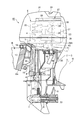
- FIG. 1 is a vertical cross-sectional side view of essential parts of an outboard motor according to an embodiment of the present invention.
- FIG. 2 is a diagram schematically showing a configuration around a connecting portion between the exhaust guide and the exhaust pipe.
- FIG. 3 is a perspective view showing the configuration of the catalyst device.
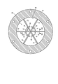
- FIG. 4 is a sectional view taken along line IV-IV in FIG.
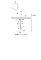
- FIG. 5 is a diagram showing a support structure of the rectifying plate.
- FIG. 6 is a sectional view taken along line VI-VI in FIG.
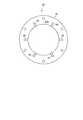
- FIG. 7 is a plan view of a connecting flange provided at the upper end of the first exhaust pipe.
- FIG. 8 is a figure which shows the modification which concerns on the support structure of the current plate.
- FIG. 9 is a diagram showing a modification of the rectifying plate.
- FIG. 10 is a diagram showing a modification of the catalyst device.
- FIG. 1 is a vertical cross-sectional side view of essential parts of an outboard motor 10 according to this embodiment.
- the terms “front, rear, left and right” are based on the plan view of the boat B to which the outboard motor 10 is attached.
- the outboard motor 10 includes a casing C.
- the casing C includes a mount case 1, an extension case 2 coupled to a lower end surface of the mount case 1, and a lower portion of the extension case 2. And a gear case 3 coupled to the end face.
- a multi-cylinder engine E is mounted on the upper end surface of the mount case 1 with the crankshaft 4 vertically placed.
- the outboard motor 10 is provided with a pair of left and right upper arms 12 that support the mount case 1 through the upper mount rubber 11, and a pair of left and right lower arms 14 that support the extension case 2 through the lower mount rubber 13.
- a swivel shaft 15 is connected between the upper arm 12 and the lower arm 14.
- a swivel case 16 that rotatably supports the swivel shaft 15 is supported by a stern bracket 17 attached to the transom Ba of the boat B so as to be vertically swingable via a horizontal tilt shaft 18.
- An annular under cover (not shown) made of synthetic resin is fixed to the mount case 1.
- the under cover covers the periphery of the section from the lower part of the engine E to the upper part of the extension case 2, and an engine hood 21 that covers the engine E from above is detachably attached to the upper end of the under cover.
- the engine hood 21 and the undercover define an engine room 23 that houses the engine E.
- An air intake 24 to the engine room 23 is provided in the upper part of the engine hood 21.
- the drive shaft 6 is connected to the lower end of the crank shaft 4 together with the flywheel 5.
- the drive shaft 6 extends downward inside the extension case 2, and its lower end is connected to a horizontal propeller shaft 8 through a forward/reverse switching mechanism 7 provided inside the gear case 3, and the rear of the propeller shaft 8 is connected to the propeller shaft 8.
- the propeller 9 is fixed to the end.
- the engine E has a crankcase 25 supporting the vertically mounted crankshaft 4, a cylinder block 26 extending rearward from the crankcase 25, and a cylinder head 27 joined to the rear end of the cylinder block 26.
- the lower surface of the crankcase 25 is bolted to the mount case 1.
- the cylinder bracket includes a plurality of cylinders 28 arranged vertically.
- the lower part of the gear case 3 is provided with an intake port 30 that opens on one side to take in external water.
- the external water taken in through the water intake 30 is pressure-fed as cooling water to the engine E by the water pump 32 to cool each part of the engine E.
- the cooling water that has finished cooling the engine E is discharged to the extension case 2 and is discharged to the outside through the discharge hole 33 formed in the boss of the propeller shaft 8.
- An oil pan 35 arranged at the center of the upper part of the extension case 2 is coupled to the lower surface of the mount case 1, and the oil pan 35 stores lubricating oil supplied to each part of the engine E.
- the cylinder head 27 rotatably supports left and right camshafts 36 for valve actuation, which are parallel to the crankshaft 4, and is a belt type timing mechanism for driving the camshafts 36 from the crankshaft 4 at a predetermined reduction ratio.
- a transmission device 37 is arranged above the cylinder block 26.
- the cylinder head 27 is provided with an exhaust manifold 39 communicating with a plurality of exhaust ports, and an exhaust outlet 39A opening at the lower end of the exhaust manifold 39 communicates with a tubular exhaust passage 40 extending to the lower surface of the mount case 1.
- the exhaust passage 40 is joined to an exhaust guide 41, which is connected to the oil pan 35 in the extension case 2, on the lower surface of the mount case 1.
- a connecting flange 45 formed at the upper end of the exhaust pipe 44 is flange-fitted to the lower end of the exhaust guide 41 by a bolt 46.
- the exhaust pipe 44 extends downward inside the extension case 2, and a lower end portion 44A of the exhaust pipe 44 opens in the casing C. Near the height of the lower end portion 44A, the waterline W of the boat B during normal traveling is located.
- a catalyst device 48 that purifies the exhaust gas D (FIG. 2) and an exhaust flow that is located on the inlet side of the catalyst device 48 and that controls the flow of the exhaust gas D to the catalyst device 48.
- Each of the control units 50 is arranged in the exhaust pipe 44.
- FIG. 2 is a diagram schematically showing the configuration around the joint between the exhaust guide 41 and the exhaust pipe 44.
- the exhaust pipe 44 is configured by connecting a first exhaust pipe 52 and a second exhaust pipe 55.
- the first exhaust pipe 52 is a pipe body extending linearly in the vertical direction, in which the connecting flange 45 of the upper end portion 52A is flange-connected to the exhaust guide 41 with the packing 47 sandwiched therebetween, and the connecting flange is also connected to the lower end portion 52B thereof. 53 is provided.
- the second exhaust pipe 55 is a pipe body in which a connecting flange 56 is formed on the upper end portion 55A thereof, and the connecting flange 56 is flange-joined to the connecting flange 53 of the first exhaust pipe 52 with a packing 57 sandwiching a packing 57.
- the second exhaust pipe 55 is a pipe body in which at least the upper end portion 52A extends linearly in the vertical direction and the middle portion is bent appropriately, and the lower end portion thereof is opened into the casing C as an exhaust port of the exhaust pipe 44. ..
- the exhaust flow control unit 50 is arranged at the connecting portion X1 of the first exhaust pipe 52 extending in the vertical direction and the exhaust guide 41. Further, the catalyst device 48 is arranged in a portion of the second exhaust pipe 55 that extends in the vertical direction and in the vicinity of the connecting portion X2 with the first exhaust pipe 52.
- FIG. 3 is a perspective view showing the configuration of the catalyst device 48.
- the catalyst device 48 includes a metal outer cylinder 60 and a catalyzer element (also referred to as “catalyst”) 61 provided in the outer cylinder 60.
- the outer cylinder 60 is formed in a cylindrical shape having a cross-sectional diameter slightly smaller than that of the second exhaust pipe 55, and is fitted into the upper end portion 55A of the second exhaust pipe 55 and fixed by welding.
- the catalyzer element 61 is a so-called metal honeycomb catalyst in which a flat plate 63 and a corrugated plate 64 each made of a metal foil are stacked and wound into a columnar shape, and a metal catalyst is supported on the flat plate 63 and the corrugated plate 64 by plating.
- the exhaust gas D flows through a plurality of cells 65, which are exhaust passages formed between the flat plate 63 and the corrugated plate 64 and extending in the central axis direction of the outer cylinder 60, and acts on the metal catalyst while flowing through the cells 65.
- HC, CO, NOx, etc. are removed and purified.
- Platinum (Pt), rhodium (Rh), palladium (Pd), or the like is used as the metal catalyst.
- the catalyzer element 61 has a thickness H smaller than the diameter F of the cross section, and a tip surface 60A that is a surface on the side where the exhaust gas D flows (that is, a surface on the inlet side) and a surface on the side where the exhaust gas D flows out.
- a certain rear end face 60B is formed in a flat, so-called disc shape. Since the thickness H is small, the heat received by the catalyzer element 61 from the exhaust gas D is rapidly transferred from the front end surface 60A to the rear end surface 60B, and the temperature rises in the thickness direction of the catalyzer element 61 as a whole. Since the purifying action of the metal catalyst increases as the temperature increases, the purifying action is enhanced over the entire thickness of the catalyzer element 61 and the purifying efficiency of the exhaust gas D is enhanced.
- FIG. 4 is a sectional view taken along line IV-IV in FIG.
- the exhaust flow control unit 50 is arranged at the upper end portion 52A of the first exhaust pipe 52, changes the flow of the exhaust gas D flowing into the catalyst device 48 located downstream thereof, and further enhances the purification efficiency of the catalyst device 48. It is a unit.
- the exhaust flow control unit 50 includes a plurality of columns 72 radially extending from the central axis K of the exhaust pipe 44 (that is, the central portion of the flow of the exhaust gas D) in the radial direction of the exhaust pipe 44.
- Each of the columns 72 has a rectifying plate 70 extending toward the catalyst device 48 in a direction perpendicular to the extending direction of the columns 72.
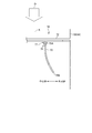
- FIG. 5 is a diagram showing a support structure of the flow straightening plate 70.
- Each of the flow regulating plates 70 is a rectangular plate that changes the flow of the exhaust gas D flowing into the catalyst device 48, surrounds the central axis K of the exhaust pipe 44 as shown in FIG. 4, and as shown in FIG.
- the upper end portion 70A is fixed to the fixing portion 77 provided on the bottom portion of the support column 72 (that is, the side facing the catalyst device 48) in a posture extending in parallel with the central axis K.
- the fixing portion 77 has a pair of holding pieces 76 made of a plastic material (for example, metal).
- the pair of sandwiching pieces 76 are constituted by projections having a shape projecting toward the catalyst device 48 and sandwiching the upper end portion 70A of the flow regulating plate 70 therebetween, and such a shape suppresses an increase in pressure loss due to the pair of sandwiching pieces 76.
- the pair of holding pieces 76 are caulked with the straightening plate 70 sandwiched therebetween, so that the straightening plate 70 is easily and firmly fixed to the column 72 so as not to fall.
- the fixing portion 77 and the sandwiching piece 76 are set within the projection surface of the column 72 without protruding from the column 72 in a plan view seen from the upstream side of the flow of the exhaust gas D. It is formed in a dimensional shape, and the pressure loss does not increase due to the fixing portion 77 and the holding piece 76.
- the lower end portion 70B of the rectifying plate 70 is a free end, and as shown in FIG. 5, as the flow rate of the exhaust gas D increases, in other words, the amount of heat received from the exhaust gas D increases, the lower end portion 70B thereof. Deforms so as to warp toward the outer peripheral side of the exhaust pipe 44. By this deformation, the flow of the exhaust gas D is changed so that the exhaust gas D flowing on the central axis K side flows on the outer peripheral side.
- the rectifying plate 70 is composed of so-called bimetal, which is formed by laminating two thin metal plates having different thermal expansion coefficients into one plate.
- the rectifying plate 70 is arranged such that the high thermal expansion coefficient surface 80 of the metal plate having the higher thermal expansion coefficient is oriented toward the central axis K, and the high thermal expansion coefficient surface 80 has the lower thermal expansion coefficient due to the heat of the exhaust gas D.
- the metal plate expands more than the low thermal expansion coefficient surface 81.
- the rectifying plate 70 is deformed into a shape in which the lower end portion 70B is bent from the middle thereof toward the outer peripheral side.
- the exhaust gas D flowing through the exhaust pipe 44 has a velocity distribution that is faster in the central portion than in the radial outer peripheral side due to the fluid resistance with the pipe wall of the exhaust pipe 44.
- the exhaust gas D flows into the catalyzer element 61 of the catalyst device 48 with this velocity distribution, the temperature on the outer peripheral side of the catalyzer element 61 becomes lower than that on the center side, and on the outer peripheral side, the purifying action toward the center side is performed. Can't get
- the exhaust flow control unit 50 described above is arranged on the upstream side of the catalyst device 48, and the exhaust flow control unit 50 causes the exhaust gas flowing on the central axis K side.
- the flow of the exhaust gas D is changed so that D flows on the outer peripheral side.
- the catalyzer element 61 the amount of the exhaust gas D flowing on the outer peripheral side is increased and the temperature on the outer peripheral side is raised, so that the purifying action on the outer peripheral side is also enhanced and the purification efficiency of the exhaust gas D is further enhanced.
- the catalyzer element 61 containing a relatively large amount of precious metal can be downsized, and the cost of the catalyst device 48 can be reduced.
- the material of the bimetal forming the rectifying plate 70 is a characteristic value such as an allowable temperature range, an elastic coefficient, a bending coefficient, an assumed temperature of the exhaust gas D (estimated heat amount), a deformation amount (warpage amount) required of the rectifying plate 70. It is selected based on The rectifying plate 70 of this embodiment uses a bimetal in which the metal plate on the high thermal expansion coefficient surface 80 side is made of Ni—Cr—Fe and the metal plate on the low thermal expansion coefficient surface 81 side is made of Cr—Fe.
- the rectification plate 70 is made of bimetal, and the rectification plate 70 is arranged in parallel with the central axis K of the exhaust pipe 44, so that an increase in pressure loss at the start of the engine E is suppressed.
- FIG. 6 is a sectional view taken along line VI-VI in FIG.
- the flow straightening plate 70 is formed in a substantially trapezoidal shape in which the lateral width G gradually increases from the upper end portion 70A to the lower end portion 70B.
- the exhaust gas D is less likely to enter the inside of the rectifying plate 70 (the side of the central axis K) on the lower end portion 70B side of the rectifying plate 70, that is, the side closer to the catalyst device 48, and the exhaust gas D is provided on the outer peripheral side of the catalyzer element 61.
- a decrease in the flow rate of the exhaust gas D flowing in is suppressed.
- the width of the upper end portion 70A is substantially the same as the width of the sandwiching piece 77, and the pressure loss at the upper end portion 70A is suppressed.
- the width of the upper end portion 70A may be equal to or smaller than the width of the sandwiching piece 77.
- each of the plurality of columns 72 that supports the flow regulating plate 70 is parallel to the tip surface 60A of the catalyzer element 61, and the exhaust pipe 44 has the same structure. It extends radially from the central axis K.
- the structure of the support column 72 in the cross section of the exhaust pipe 44, the flow of the exhaust gas D is suppressed on the side of the central axis K as compared to the outer peripheral side, so the velocity distribution of the exhaust gas D flowing into the catalyst device 48 in the radial direction. Bias of is suppressed.
- each of the columns 72 has a triangular prism shape with a triangular cross section, and as shown in FIG.
- the width is narrowed toward the inlet side of the exhaust gas D (that is, the engine E side), and the central axis of the exhaust gas D is reduced.
- the turbulence of the flow in the K direction due to the support columns 72 is suppressed as much as possible.
- FIG. 7 is a plan view of the coupling flange 45 provided on the upper end portion 52A of the first exhaust pipe 52.
- the upper surface 45A of the coupling flange 45 which is the coupling surface with the exhaust guide 41, is provided with a plurality of recesses 85 into which the tips of the columns 72 of the exhaust flow control unit 50 enter.
- the tip portions of the columns 72 of the exhaust flow control unit 50 are hooked in the respective recesses 85 of the connecting flange 45 of the first exhaust pipe 52, and the state thereof is set.
- the exhaust flow control unit 50 is fixed inside the exhaust pipe 44 by connecting the connecting flange 45 to the exhaust guide 41 and closing the open end of each recess 85 with the exhaust guide 41 (more accurately, the packing 45).
- the exhaust flow control unit 50 is simply hooked in the recess 85 of the connecting flange 45 of the first exhaust pipe 52, so that the assembly work becomes easy. Further, even when it becomes necessary to replace the exhaust flow control unit 50, the exhaust flow control unit 50 can be easily replaced by simply removing the first exhaust pipe 52 (exhaust pipe 44) from the exhaust guide 41.
- the exhaust flow control unit 50 has a fixed structure in which a plurality of recesses 85 are provided in the coupling surface of the exhaust guide 41, which is the side to which the upper end of the exhaust pipe 44 is coupled, and the recesses 85 of the exhaust flow control unit 50 are provided.
- the structure may be such that the tip ends of the columns 72 are engaged, and each tip part is sandwiched and fixed between the coupling surface of the exhaust guide 41 and the upper end of the exhaust pipe 44.
- the exhaust flow control unit 50 of the present embodiment has a plurality of rectifying plates 70 that change the flow of the exhaust gas D, and a plurality of columns 72 that support each of the rectifying plates 70 on the inlet side of the catalyst device 48.
- each of the columns 72 extends substantially in parallel with the tip surface 60A of the catalyst device 48 and radially, and each of the rectifying plates 70 has an inlet side of the catalyst device 48 in a direction perpendicular to the extending direction of the columns 72. Extend toward.
- the purification efficiency of the catalyst device 48 is improved.
- each rectifying plate 70 extends toward the entrance side of the catalyst device 48 in a direction perpendicular to the extending direction of the support column 72, for example, a guide plate for rectifying such as a butterfly valve is provided in the catalyst device 48. Since the increase in pressure loss is suppressed as compared with the configuration arranged on the inlet side, a sufficiently practical exhaust flow control unit 50 can be obtained.
- the respective tip portions of the support columns 72 are respectively provided in the plurality of recesses 85 provided on the upper surface 45A of the connecting flange 45 at the upper end portion of the exhaust pipe 44 where the catalyst device 48 is provided.
- the exhaust pipe 44 and the exhaust guide 41 are arranged at the joint portion X1. Therefore, the exhaust flow control unit 50 can be incorporated into the exhaust pipe 44 simply by being hooked in the recess 85 of the connecting flange 45, which facilitates the assembling work. Further, even when it becomes necessary to replace the exhaust flow control unit 50, the exhaust flow control unit 50 can be easily replaced by simply removing the exhaust pipe 44 from the exhaust guide 41.
- each of the columns 72 is provided with a sandwiching piece 76, which is a pair of protrusions between which the rectifying plate 70 is sandwiched, provided on the side facing the catalyst device 48, the sandwiching piece is provided. The increase in pressure loss due to 76 is suppressed.
- the straightening plate 70 is fixed to the column 72 by crimping the pair of sandwiching pieces 76, so that the straightening plate 70 can be fixed easily and firmly.
- each of the flow control plates 70 is made of bimetal, and the high thermal expansion coefficient surface 80 having the higher thermal expansion coefficient is directed toward the central axis K which is the center side of the flow of the exhaust gas D.
- the low thermal expansion coefficient surface 81 having the lower thermal expansion coefficient is supported by the column 72 so as to face the outer peripheral side of the flow of the exhaust gas D.
- the high thermal expansion coefficient surface 80 expands by the heat of the exhaust gas D more than the low thermal expansion coefficient surface 81 of the metal plate having the lower thermal expansion coefficient
- the rectifying plate 70 has the lower end portion 70B from the middle to the outer periphery. It transforms into a curved shape that approaches toward the side.
- the flow rate of the exhaust gas D flowing on the outer peripheral side is increased, and the temperature on the outer peripheral side of the catalyzer element 61 is increased. Therefore, the purifying action on the outer peripheral side is also enhanced and the exhaust gas D is purified. Efficiency is improved.
- each of the rectifying plates 70 has a lower end portion 70B having an upper end portion 70A on the side supported by the column 72 having the same width as the sandwiching piece 76 and a lower end portion 70B close to the inlet side of the catalyst device 48. Is wider than the upper end portion 70A.
- the exhaust gas D is less likely to enter the inside of the rectifying plate 70 (the side of the central axis K) on the lower end portion 70B side of the rectifying plate 70, that is, the side closer to the catalyst device 48, and the exhaust gas D is provided on the outer peripheral side of the catalyzer element 61.
- a decrease in the flow rate of the exhaust gas D flowing in is suppressed.
- the width of the upper end portion 70A of the rectifying plate 70 is the same as the width of the sandwiching piece 77, the pressure loss at the upper end portion 70A is suppressed.
- the material of the high thermal expansion coefficient surface 80 and the material of the low thermal expansion coefficient surface 81 of each of the rectifying plates 70 are Ni—Cr—Fe.
- the rectifying plate 70 can be deformed so that a desired flow of the exhaust gas D can be obtained.
- each of the columns 72 has a triangular shape in which the width on the side on which the exhaust gas D flows is narrowed, so the columns 72 for the flow of the exhaust gas D in the direction of the central axis K. Disturbance due to is suppressed.
- the rivets 90 when supporting the flow regulating plate 70 on the support columns 72, instead of caulking the clamping pieces 76 that are the protrusions of the fixing portion 77, as shown in FIG. 8, the rivets 90 are supported by the pair of clamping pieces 76.
- the rivet 90 may be swaged through the extending direction of 72.
- each of the straightening plates 70 has a shape in which the upper end portion 70A has the same width as the sandwiching piece 76 and the lower end portion 70B has a larger width than the upper end portion 70A.
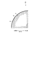
- the diameter of the cell 65 of the catalyst device 48 catalyzer element 61 may be larger on the outer peripheral side than on the central side of the flow of the exhaust gas D, as shown in FIG. 10.
- the exhaust gas D flowing into the catalyzer element 61 easily passes through the outer peripheral side, and the temperature in the radial direction of the catalyzer element 61 can be made more uniform.
- illustration of a part of the cells 65 is omitted.
- the horizontal and vertical directions, various numerical values, and shapes are conscious of the directions, the range around the numerical values, and the approximate shape unless otherwise specified. This does not exclude the same range of effects, and includes the peripheral range and the approximate shape (so-called equivalent range) as long as the numerical values do not deviate from the critical significance.
- connection flange 45A Top surface of connection flange (connection surface) 48 catalyst device 50 exhaust flow control unit 52 first exhaust pipe 55 second exhaust pipe 60A front end face 60B rear end face 61 catalyzer element (catalyst) 65 cell 70 straightening plate 72 column 80 high coefficient of thermal expansion surface 81 low coefficient of thermal expansion surface 85 recess 90 rivet G lateral width H thickness K central axis
Landscapes
- Chemical & Material Sciences (AREA)
- Engineering & Computer Science (AREA)
- Chemical Kinetics & Catalysis (AREA)
- Health & Medical Sciences (AREA)
- Toxicology (AREA)
- Combustion & Propulsion (AREA)
- Mechanical Engineering (AREA)
- General Engineering & Computer Science (AREA)
- Exhaust Gas Treatment By Means Of Catalyst (AREA)
- Exhaust Gas After Treatment (AREA)
Abstract
触媒の入側に設けられる実用的な排気流制御ユニットを提供すること。 船外機10のエンジンEの排気ガスを浄化する触媒装置48の入側に配置され、前記触媒装置48に向かう排気ガスの流れを制御する排気流制御ユニット50であって、前記排気ガスの流れを変更する複数の整流プレート70と、前記整流プレート70のそれぞれを、前記触媒装置48の入側で支持する複数の支柱72と、を備え、前記支柱72のそれぞれは、前記触媒装置48の先端面60Aに対して略平行に、かつ放射状に延び、前記整流プレート70は、前記支柱72の延びる方向に対し垂直方向に前記触媒装置48に向けて延びる。
Description
本発明は、排気流制御ユニットに関する。
エンジンの排気ガスの経路内に触媒を設け、当該触媒によって排気ガスを浄化する技術が知られている(例えば、特許文献1参照)。また、特許文献1には、触媒の入側に整流用のガイド板を設けることで排気ガスを触媒に均一に流入させ、効率的に排気ガスを浄化することが記載されている。
特許文献1に記載されているように、整流用のガイド板を設けることは実用性の点で問題があった。
本発明は、触媒の入側に設けられる実用的な排気流制御ユニットを提供することを目的とする。
本発明は、触媒の入側に設けられる実用的な排気流制御ユニットを提供することを目的とする。
この明細書には、2019年2月1日に出願された日本国特許出願・特願2019-017339の全ての内容が含まれる。
本発明は、船外機のエンジンの排気ガスを浄化する触媒の入側に配置され、前記触媒に向かう排気ガスの流れを制御する排気流制御ユニットであって、前記排気ガスの流れを変更する複数の整流プレートと、前記整流プレートのそれぞれを、前記触媒の入側で支持する複数の支柱と、を備え、前記支柱のそれぞれは、前記触媒の先端面に対して略平行に、かつ放射状に延び、前記整流プレートは、前記支柱の延びる方向に対し垂直方向に前記触媒に向けて延びることを特徴とする。
本発明は、船外機のエンジンの排気ガスを浄化する触媒の入側に配置され、前記触媒に向かう排気ガスの流れを制御する排気流制御ユニットであって、前記排気ガスの流れを変更する複数の整流プレートと、前記整流プレートのそれぞれを、前記触媒の入側で支持する複数の支柱と、を備え、前記支柱のそれぞれは、前記触媒の先端面に対して略平行に、かつ放射状に延び、前記整流プレートは、前記支柱の延びる方向に対し垂直方向に前記触媒に向けて延びることを特徴とする。
本発明は、上記排気流制御ユニットにおいて、前記支柱のそれぞれの先端部は、前記触媒が設けられる排気管と、当該排気管の上端部が結合される他の管体とのいずれかの結合面内に設けられた複数の凹部のそれぞれに係合し、前記排気管と、前記他の管体との結合部に配置されることを特徴とする。
本発明は、上記排気流制御ユニットにおいて、前記支柱のそれぞれは、前記整流プレートが間に挟まれる一対の突起が前記触媒と対向する側に設けられていることを特徴とする。
本発明は、上記排気流制御ユニットにおいて、前記一対の突起がかしめられることで前記整流プレートが前記支柱に固定されることを特徴とする。
本発明は、上記排気流制御ユニットにおいて、前記一対の突起に通されたリベットによって前記整流プレートが前記支柱に固定されることを特徴とする。
本発明は、上記排気流制御ユニットにおいて、前記整流プレートのそれぞれは、前記触媒の入側に近い端部が、前記支柱に支持された側の端部よりも、前記排気ガスの流れの外周側に近づくように曲がっていることを特徴とする。
本発明は、上記排気流制御ユニットにおいて、前記支柱のそれぞれは、前記整流プレートが間に挟まれる一対の突起が前記触媒と対向する側に設けられており、前記整流プレートのそれぞれは、前記支柱に支持された側の端部が前記突起と同じ幅であり、前記触媒の入側に近い端部の幅が、前記支柱に支持された側の端部よりも大きい、ことを特徴とする。
本発明は、上記排気流制御ユニットにおいて、前記整流プレートのそれぞれは、バイメタルから成り、熱膨張率が高い方の面を前記排気ガスの流れの中心に向け、熱膨張率が低い方の面を前記排気ガスの流れの外周側に向けて前記支柱に支持されることを特徴とする。
本発明は、上記排気流制御ユニットにおいて、前記支柱のそれぞれは、前記整流プレートが間に挟まれる一対の突起が前記触媒と対向する側に設けられており、前記整流プレートのそれぞれは、前記支柱に支持された側の端部が前記突起と同じ幅であり、前記触媒の入側に近い端部の幅が、前記支柱に支持された側の端部よりも大きい、ことを特徴とする。
本発明は、上記排気流制御ユニットにおいて、前記整流プレートのそれぞれは、熱膨張率が高い方の面の材質がNi-Cr-Feであり、熱膨張率が低い方の面の材質がCr-Feであることを特徴とする。
本発明は、上記排気流制御ユニットにおいて、前記支柱のそれぞれの断面は、前記排気ガスが流れ込む側の幅が狭くなる三角形であることを特徴とする。
本発明は、上記排気流制御ユニットにおいて、前記触媒のセルの径は、前記排気ガスの流れの中心側に比べ外周側が大きいことを特徴とする。
本発明によれば、触媒の入側に設けられる実用的な排気流制御ユニットが得られる。
以下、図面を参照して本発明の実施形態について説明する。
図1は、本実施形態に係る船外機10の要部縦断側面図である。なお、以下の説明において、前後左右とは、船外機10が取り付けられる舟艇Bを平面視した状態を基準にして言うものとする。
図1に示すように、船外機10はケーシングCを有し、このケーシングCは、マウントケース1と、このマウントケース1の下端面に結合されるエクステンションケース2と、このエクステンションケース2の下端面に結合されるギヤケース3と、により構成される。マウントケース1の上端面には、多気筒のエンジンEがクランク軸4を縦置きにして搭載される。
図1は、本実施形態に係る船外機10の要部縦断側面図である。なお、以下の説明において、前後左右とは、船外機10が取り付けられる舟艇Bを平面視した状態を基準にして言うものとする。
図1に示すように、船外機10はケーシングCを有し、このケーシングCは、マウントケース1と、このマウントケース1の下端面に結合されるエクステンションケース2と、このエクステンションケース2の下端面に結合されるギヤケース3と、により構成される。マウントケース1の上端面には、多気筒のエンジンEがクランク軸4を縦置きにして搭載される。
船外機10には、アッパマウントゴム11を介してマウントケース1を支持する左右一対のアッパアーム12と、ロアマウントゴム13を介してエクステンションケース2を支持する左右一対のロアアーム14とが設けられる。これらアッパアーム12とロアアーム14との間にスイベル軸15が連結される。また、このスイベル軸15を回転自在に支持するスイベルケース16が、舟艇BのトランサムBaに装着されるスターンブラケット17に水平方向のチルト軸18を介して上下揺動可能に支持される。
マウントケース1には、合成樹脂製で環状のアンダカバー(図示せず)が固着される。このアンダカバーは、エンジンEの下部からエクステンションケース2の上部までの区間の周囲を覆うもので、その上端に、エンジンEを上方から覆うエンジンフード21が着脱可能に取り付けられる。このエンジンフード21及びアンダカバーにより、エンジンEを収容するエンジンルーム23が画成される。このエンジンルーム23への空気取り入れ口24がエンジンフード21の上部に設けられる。
クランク軸4の下端には、フライホイール5と共に駆動軸6が連結される。この駆動軸6は、エクステンションケース2の内部を下方に延び、その下端はギヤケース3の内部に設けた前進後進切換機構7を介して水平方向のプロペラ軸8に接続され、このプロペラ軸8の後端にプロペラ9が固着される。
エンジンEは、縦置きのクランク軸4を支持するクランクケース25と、このクランクケース25から後方に延びるシリンダブロック26と、このシリンダブロック26の後端に接合されるシリンダヘッド27とを有しており、クランクケース25の下面がマウントケース1にボルト結合される。シリンダブラケットは、上下に配列する複数本の気筒28を備える。
ギヤケース3の下部には、その一側面に開口して外部の水を取り入れる取水口30が設けられる。この取水口30から取り入れられた外水が水ポンプ32によってエンジンEに冷却水として圧送され、エンジンEの各部を冷却する。エンジンEを冷却し終えた冷却水は、エクステンションケース2に放出され、そしてプロペラ軸8のボスに形成される排出孔33を通して外部に排出される。
マウントケース1の下面には、エクステンションケース2内の上部中央に配置されるオイルパン35が結合され、このオイルパン35には、エンジンEの各部に供給される潤滑オイルが貯留される。
シリンダヘッド27には、クランク軸4と平行な動弁用の左右それぞれのカム軸36が回転自在に支持され、クランク軸4からこれらカム軸36を所定の減速比をもって駆動するベルト式の調時伝動装置37がシリンダブロック26の上方に配設される。
シリンダヘッド27には、複数の排気ポートに連通する排気マニフォルド39が設けられ、この排気マニフォルド39の下端に開口する排気出口39Aは、マウントケース1の下面に延びる管状の排気通路40に連通する。この排気通路40は、マウントケース1の下面において、エクステンションケース2内のオイルパン35に連設された排気ガイド41に接合される。排気ガイド41の下端部には、排気管44の上端に形成された連結フランジ45がボルト46によりフランジ結合される。排気管44は、エクステンションケース2の内部において下方に延び、その下端部44AがケーシングCの中で開放する。この下端部44Aの高さの近傍に、舟艇Bの通常走航時の喫水線Wが位置する。
そして、この船外機10では、排気ガスD(図2)を浄化する触媒装置48と、この触媒装置48の入側に位置し、触媒装置48への排気ガスDの流れを制御する排気流制御ユニット50とのそれぞれが排気管44の中に配設される。
図2は、排気ガイド41と排気管44との結合箇所周辺の構成を模式的に示す図である。
同図に示すように、排気管44は、第1排気管52と、第2排気管55と、を連結して構成される。
第1排気管52は、上端部52Aの上記連結フランジ45が排気ガイド41にパッキング47を挟んでフランジ結合される、鉛直方向に直線状に延びる管体であり、その下端部52Bにも連結フランジ53が設けられる。第2排気管55は、その上端部55Aに連結フランジ56が形成された管体であり、当該連結フランジ56が第1排気管52の連結フランジ53にパッキン57を挟んでボルト54によりフランジ結合される。第2排気管55は、少なくとも上端部52Aが鉛直方向に直線状に延び、途中が適宜に屈曲した管体であり、その下端部が排気管44の排気口としてケーシングCの中に開放される。
同図に示すように、排気管44は、第1排気管52と、第2排気管55と、を連結して構成される。
第1排気管52は、上端部52Aの上記連結フランジ45が排気ガイド41にパッキング47を挟んでフランジ結合される、鉛直方向に直線状に延びる管体であり、その下端部52Bにも連結フランジ53が設けられる。第2排気管55は、その上端部55Aに連結フランジ56が形成された管体であり、当該連結フランジ56が第1排気管52の連結フランジ53にパッキン57を挟んでボルト54によりフランジ結合される。第2排気管55は、少なくとも上端部52Aが鉛直方向に直線状に延び、途中が適宜に屈曲した管体であり、その下端部が排気管44の排気口としてケーシングCの中に開放される。
排気流制御ユニット50は、鉛直方向に延びる第1排気管52と排気ガイド41の結合部X1に配設される。また触媒装置48は、第2排気管55の中の鉛直方向に延びる箇所であって第1排気管52との結合部X2の近傍に配設される。
図3は、触媒装置48の構成を示す斜視図である。
触媒装置48は、金属製の外筒60と、外筒60に内設されたキャタライザエレメント(「触媒」とも称される)61と、を備える。外筒60は、第2排気管55よりも僅かに小さな断面径の円筒形に形成され、第2排気管55の上端部55Aに嵌め込まれ溶接によって固着される。
キャタライザエレメント61は、それぞれ金属箔からなる平板63及び波板64が重ねて巻かれて円柱状に形成され、これら平板63及び波板64に金属触媒をめっきによって担持させた、いわゆるメタルハニカム触媒であり、外筒60の内周面に、ろう付けや溶接等により固定されている。
排気ガスDは、平板63及び波板64との間に形成された、外筒60の中心軸方向に延びる排気通路である複数のセル65を流れ、セル65を流れる間に金属触媒と作用してHCやCO、NOx等が除去され浄化される。金属触媒には、プラチナ(Pt)やロジウム(Rh)、パラジウム(Pd)などが用いられる。
触媒装置48は、金属製の外筒60と、外筒60に内設されたキャタライザエレメント(「触媒」とも称される)61と、を備える。外筒60は、第2排気管55よりも僅かに小さな断面径の円筒形に形成され、第2排気管55の上端部55Aに嵌め込まれ溶接によって固着される。
キャタライザエレメント61は、それぞれ金属箔からなる平板63及び波板64が重ねて巻かれて円柱状に形成され、これら平板63及び波板64に金属触媒をめっきによって担持させた、いわゆるメタルハニカム触媒であり、外筒60の内周面に、ろう付けや溶接等により固定されている。
排気ガスDは、平板63及び波板64との間に形成された、外筒60の中心軸方向に延びる排気通路である複数のセル65を流れ、セル65を流れる間に金属触媒と作用してHCやCO、NOx等が除去され浄化される。金属触媒には、プラチナ(Pt)やロジウム(Rh)、パラジウム(Pd)などが用いられる。
キャタライザエレメント61は、厚みHが断面の径Fよりも小さく、なおかつ、排気ガスDが流れ込む側の面(すなわち、入側の面)である先端面60Aと、排気ガスDが流れ出る側の面である後端面60Bとがそれぞれ平面の、いわゆる円盤状に形成される。厚みHが小さいことで、キャタライザエレメント61が排気ガスDから受けた熱が先端面60Aから後端面60Bまで速やかに伝達し、キャタライザエレメント61の厚さ方向において全体的に温度が上昇する。金属触媒は温度が高いほど浄化作用が高まるため、キャタライザエレメント61の厚さ方向の全体に亘って浄化作用が高められ、排気ガスDの浄化効率が高められる。
図4は、図2におけるIV-IV線断面図である。
排気流制御ユニット50は、第1排気管52の上端部52Aに配設され、その下流に位置する触媒装置48に流れ込む排気ガスDの流れを変更し、この触媒装置48の浄化効率を一層高めるユニットである。図4に示すように、排気流制御ユニット50は、排気管44の中心軸K(すなわち、排気ガスDの流れの中心部)から放射状に当該排気管44の径方向に延びる複数の支柱72と、支柱72のそれぞれに、当該支柱72の延在方向に対して垂直方向に触媒装置48に向けて延びる整流プレート70と、を有する。
排気流制御ユニット50は、第1排気管52の上端部52Aに配設され、その下流に位置する触媒装置48に流れ込む排気ガスDの流れを変更し、この触媒装置48の浄化効率を一層高めるユニットである。図4に示すように、排気流制御ユニット50は、排気管44の中心軸K(すなわち、排気ガスDの流れの中心部)から放射状に当該排気管44の径方向に延びる複数の支柱72と、支柱72のそれぞれに、当該支柱72の延在方向に対して垂直方向に触媒装置48に向けて延びる整流プレート70と、を有する。
図5は、整流プレート70の支持構造を示す図である。
整流プレート70のそれぞれは、触媒装置48に流れ込む排気ガスDの流れを変更する矩形状のプレートであり、図4に示すように排気管44の中心軸Kを取り囲み、かつ、図5に示すように中心軸Kに平行に延在する姿勢で、その上端部70Aが支柱72の底部(すなわち、触媒装置48と対向する側)に設けられた固定部77に固定される。この固定部77は、塑性を有した材料(例えば金属)から成る一対の挟持片76を有する。一対の挟持片76は、整流プレート70の上端部70Aを間に挟む、触媒装置48に向けて突出した形状の突起によって構成されており、かかる形状によって一対の挟持片76による圧損の増加が抑えられている。そして、一対の挟持片76は、整流プレート70を間に挟んだ状態でかしめられることで、簡単、かつ強固に整流プレート70が支柱72に落下不能に固定される。
さらに固定部77と、その挟持片76とは、図4に示すように、排気ガスDの流れの上流側から視た平面視で支柱72から突出することなく、支柱72の投影面内に収まる寸法形状で形成されており、固定部77と、その挟持片76とによって圧損が増加しないようになっている。
整流プレート70のそれぞれは、触媒装置48に流れ込む排気ガスDの流れを変更する矩形状のプレートであり、図4に示すように排気管44の中心軸Kを取り囲み、かつ、図5に示すように中心軸Kに平行に延在する姿勢で、その上端部70Aが支柱72の底部(すなわち、触媒装置48と対向する側)に設けられた固定部77に固定される。この固定部77は、塑性を有した材料(例えば金属)から成る一対の挟持片76を有する。一対の挟持片76は、整流プレート70の上端部70Aを間に挟む、触媒装置48に向けて突出した形状の突起によって構成されており、かかる形状によって一対の挟持片76による圧損の増加が抑えられている。そして、一対の挟持片76は、整流プレート70を間に挟んだ状態でかしめられることで、簡単、かつ強固に整流プレート70が支柱72に落下不能に固定される。
さらに固定部77と、その挟持片76とは、図4に示すように、排気ガスDの流れの上流側から視た平面視で支柱72から突出することなく、支柱72の投影面内に収まる寸法形状で形成されており、固定部77と、その挟持片76とによって圧損が増加しないようになっている。
整流プレート70は、その下端部70Bが自由端となっており、図5に示すように、排気ガスDの流量が増えるほど、換言すれば排気ガスDから受ける熱量が高まるほど、その下端部70Bが排気管44の外周側に向けて反るように変形する。この変形により、中心軸Kの側を流れる排気ガスDが外周側を流れるように、当該排気ガスDの流れが変更される。
かかる整流プレート70は、熱膨張率の異なる2枚の薄い金属板を一枚の板状に貼り合わせた、いわゆるバイメタルによって構成される。整流プレート70は、熱膨張率が高い方の金属板の高熱膨張率面80が中心軸Kに向けて配置され、この高熱膨張率面80が排気ガスDの熱によって、熱膨張率が低い方の金属板の低熱膨張率面81よりも大きく膨張する。これにより、整流プレート70は、図5に示すように、その途中から下端部70Bが外周側に向けて近づく方向に曲がった形状に変形する。
排気管44を流れる排気ガスDは、排気流制御ユニット50が存在しない場合、排気管44の管壁との流体抵抗により、径方向の外周側よりも中心部が速い速度分布を有する。そして、この速度分布のまま排気ガスDが触媒装置48のキャタライザエレメント61に流れ込んだ場合には、キャタライザエレメント61の外周側の温度が中心側よりも低くなり、外周側では中心側ほどの浄化作用が得られない。
これに対して、本実施形態の船外機10では、上記の排気流制御ユニット50を触媒装置48の上流側に配置し、この排気流制御ユニット50によって、中心軸Kの側を流れる排気ガスDが外周側を流れるように排気ガスDの流れが変更される。これにより、キャタライザエレメント61では、外周側を流れる排気ガスDの量が増大して、外周側の温度が高められるので、この外周側の浄化作用も高められ、排気ガスDの浄化効率が一層高められる。また浄化効率が高まることで、比較的高価な貴金属を多く含むキャタライザエレメント61を小型化でき、触媒装置48の低コスト化が図られる。
整流プレート70を構成するバイメタルの材質は、許容温度範囲や弾性係数、わん曲係数などの特性値、排気ガスDの想定温度(想定熱量)、整流プレート70に要求される変形量(反り量)などに基づいて選定される。本実施形態の整流プレート70には、高熱膨張率面80の側の金属板がNi-Cr-Feから成り、低熱膨張率面81の側の金属板がCr-Feから成るバイメタルが用いられる。
整流プレート70がバイメタルによって構成され、当該整流プレート70が排気管44の中心軸Kに平行に配置されることで、エンジンEの始動当初における圧損の増加が抑えられる。
図6は、図4におけるVI-VI断面線図である。
同図に示すように、整流プレート70は、上端部70Aから下端部70Bにかけて、横幅Gが順次に広がる略台形状に形成される。これにより、整流プレート70の下端部70Bの側、すなわち触媒装置48に近い側において、整流プレート70の内側(中心軸Kの側)に排気ガスDが回り込み難くなり、キャタライザエレメント61の外周側に流れ込む排気ガスDの流量低下が抑えられる。また整流プレート70は、上端部70Aの幅が上記挟持片77の幅と略同じになっており、上端部70Aでの圧損が抑えられている。なお、上端部70Aの幅は挟持片77の幅以下であってもよい。
同図に示すように、整流プレート70は、上端部70Aから下端部70Bにかけて、横幅Gが順次に広がる略台形状に形成される。これにより、整流プレート70の下端部70Bの側、すなわち触媒装置48に近い側において、整流プレート70の内側(中心軸Kの側)に排気ガスDが回り込み難くなり、キャタライザエレメント61の外周側に流れ込む排気ガスDの流量低下が抑えられる。また整流プレート70は、上端部70Aの幅が上記挟持片77の幅と略同じになっており、上端部70Aでの圧損が抑えられている。なお、上端部70Aの幅は挟持片77の幅以下であってもよい。
前掲図4に示すように、この排気流制御ユニット50では、整流プレート70を支持する複数の支柱72のそれぞれは、キャタライザエレメント61の先端面60Aに対して平行であり、なおかつ、排気管44の中心軸Kを基点として放射状に延びている。この支柱72の構成により、排気管44の断面において、外周側に比べて中心軸Kの側で排気ガスDの流れが抑えられるので、触媒装置48に流れる込む排気ガスDの径方向における速度分布の偏りが抑えられる。
また、各支柱72は断面三角形の三角柱状を成し、前掲図6に示すように、排気ガスDの入側(すなわちエンジンEの側)にかけて幅が狭くなっており、排気ガスDの中心軸Kの方向への流れの支柱72による乱れが極力抑えられている。
また、各支柱72は断面三角形の三角柱状を成し、前掲図6に示すように、排気ガスDの入側(すなわちエンジンEの側)にかけて幅が狭くなっており、排気ガスDの中心軸Kの方向への流れの支柱72による乱れが極力抑えられている。
図7は、第1排気管52の上端部52Aに設けられた連結フランジ45の平面図である。
同図に示すように、排気ガイド41との結合面となる連結フランジ45の上面45Aには、排気流制御ユニット50の各支柱72の先端部が入り込む複数の凹部85が設けられる。そして、排気流制御ユニット50を排気管44に組み込む際には、この第1排気管52の連結フランジ45の各凹部85に、排気流制御ユニット50の各支柱72の先端部を引っ掛け、その状態で、連結フランジ45を排気ガイド41に結合し、各凹部85の開放端を排気ガイド41(より正確にはパッキン45)で閉じることで、排気流制御ユニット50を排気管44内部に固定する。
同図に示すように、排気ガイド41との結合面となる連結フランジ45の上面45Aには、排気流制御ユニット50の各支柱72の先端部が入り込む複数の凹部85が設けられる。そして、排気流制御ユニット50を排気管44に組み込む際には、この第1排気管52の連結フランジ45の各凹部85に、排気流制御ユニット50の各支柱72の先端部を引っ掛け、その状態で、連結フランジ45を排気ガイド41に結合し、各凹部85の開放端を排気ガイド41(より正確にはパッキン45)で閉じることで、排気流制御ユニット50を排気管44内部に固定する。
かかる固定構造においては、排気流制御ユニット50は、第1排気管52の連結フランジ45の凹部85に引っ掛けられるだけなので、組み込み作業が容易となる。また、排気流制御ユニット50を交換する必要性が生じた場合でも、第1排気管52(排気管44)を排気ガイド41から取り外すだけで、排気流制御ユニット50を簡単に交換できる。
なお、排気流制御ユニット50の固定構造は、排気管44の上端部が結合される側である排気ガイド41の結合面内に複数の凹部85を設け、各凹部85に排気流制御ユニット50の支柱72の先端部を係合させ、各先端部を排気ガイド41の結合面と排気管44の上端部との間で挟んで固定する構造であってもよい。
上述した実施形態によれば、次の効果を奏する。
本実施形態の排気流制御ユニット50は、排気ガスDの流れを変更する複数の整流プレート70と、整流プレート70のそれぞれを、触媒装置48の入側で支持する複数の支柱72と、を有し、それぞれの支柱72は、触媒装置48の先端面60Aに対して略平行に、かつ放射状に延び、それぞれの整流プレート70は、支柱72の延びる方向に対し垂直方向に触媒装置48の入側に向けて延びる。
この排気流制御ユニット50によれば、整流プレート70による流れの変更、及び、支柱72の放射状形状によって、排気ガスDの径方向の速度分布の偏りが抑えられるので、触媒装置48の浄化効率を高めることができる。また浄化効率が高まることで、比較的高価な貴金属を多く含むキャタライザエレメント61を小型化でき、触媒装置48の低コスト化が図られる。
これに加えて、それぞれの整流プレート70は、支柱72の延びる方向に対し垂直方向に触媒装置48の入側に向けて延びるので、例えば、バタフライバルブなどの整流用のガイド板を触媒装置48の入側に配置する構成に比べ、圧損の増加が抑えられるので、十分に実用的な排気流制御ユニット50が得られる。
この排気流制御ユニット50によれば、整流プレート70による流れの変更、及び、支柱72の放射状形状によって、排気ガスDの径方向の速度分布の偏りが抑えられるので、触媒装置48の浄化効率を高めることができる。また浄化効率が高まることで、比較的高価な貴金属を多く含むキャタライザエレメント61を小型化でき、触媒装置48の低コスト化が図られる。
これに加えて、それぞれの整流プレート70は、支柱72の延びる方向に対し垂直方向に触媒装置48の入側に向けて延びるので、例えば、バタフライバルブなどの整流用のガイド板を触媒装置48の入側に配置する構成に比べ、圧損の増加が抑えられるので、十分に実用的な排気流制御ユニット50が得られる。
本実施形態の排気流制御ユニット50では、支柱72のそれぞれの先端部は、触媒装置48が設けられる排気管44の上端部の連結フランジ45の上面45Aに設けられた複数の凹部85のそれぞれに係合することで、排気管44と排気ガイド41(他の管体)との結合部X1に配置される。
したがって、連結フランジ45の凹部85に引っ掛けられるだけで排気流制御ユニット50を排気管44に組み込むことができ、組み込み作業が容易となる。また、排気流制御ユニット50を交換する必要性が生じた場合でも、排気管44を排気ガイド41から取り外すだけで、排気流制御ユニット50を簡単に交換できる。
したがって、連結フランジ45の凹部85に引っ掛けられるだけで排気流制御ユニット50を排気管44に組み込むことができ、組み込み作業が容易となる。また、排気流制御ユニット50を交換する必要性が生じた場合でも、排気管44を排気ガイド41から取り外すだけで、排気流制御ユニット50を簡単に交換できる。
本実施形態の排気流制御ユニット50では、支柱72のそれぞれは、整流プレート70が間に挟まれる一対の突起である挟持片76が触媒装置48と対向する側に設けられているので、挟持片76による圧損の増加が抑えられる。
本実施形態の排気流制御ユニット50では、一対の挟持片76がかしめられることで整流プレート70を支柱72に固定するので、簡単、かつ強固に整流プレート70を固定できる。
本実施形態の排気流制御ユニット50では、整流プレート70のそれぞれは、バイメタルから成り、熱膨張率が高い方の高熱膨張率面80を排気ガスDの流れの中心側である中心軸Kに向け、熱熱膨張率が低い方の低熱膨張率面81を排気ガスDの流れの外周側に向けて支柱72に支持される。
これにより、高熱膨張率面80が排気ガスDの熱によって、熱膨張率が低い方の金属板の低熱膨張率面81よりも大きく膨張し、整流プレート70が、その途中から下端部70Bが外周側に向けて近づくように曲がった形状に変形する。
この結果、触媒装置48では、外周側を流れる排気ガスDの流量が増大して、キャタライザエレメント61の外周側の温度が高められるので、この外周側の浄化作用も高められ、排気ガスDの浄化効率が高められる。
これにより、高熱膨張率面80が排気ガスDの熱によって、熱膨張率が低い方の金属板の低熱膨張率面81よりも大きく膨張し、整流プレート70が、その途中から下端部70Bが外周側に向けて近づくように曲がった形状に変形する。
この結果、触媒装置48では、外周側を流れる排気ガスDの流量が増大して、キャタライザエレメント61の外周側の温度が高められるので、この外周側の浄化作用も高められ、排気ガスDの浄化効率が高められる。
本実施形態の排気流制御ユニット50では、整流プレート70のそれぞれは、支柱72に支持された側の上端部70Aが挟持片76と同じ幅であり、触媒装置48の入側に近い下端部70Bの幅が上端部70Aよりも大きくなっている。
これにより、整流プレート70の下端部70Bの側、すなわち触媒装置48に近い側において、整流プレート70の内側(中心軸Kの側)に排気ガスDが回り込み難くなり、キャタライザエレメント61の外周側に流れ込む排気ガスDの流量低下が抑えられる。また整流プレート70の上端部70Aの幅が上記挟持片77の幅と同じであるため、上端部70Aでの圧損が抑えられている。
これにより、整流プレート70の下端部70Bの側、すなわち触媒装置48に近い側において、整流プレート70の内側(中心軸Kの側)に排気ガスDが回り込み難くなり、キャタライザエレメント61の外周側に流れ込む排気ガスDの流量低下が抑えられる。また整流プレート70の上端部70Aの幅が上記挟持片77の幅と同じであるため、上端部70Aでの圧損が抑えられている。
本実施形態の排気流制御ユニット50では、整流プレート70のそれぞれは、高熱膨張率面80の材質がNi-Cr-Feであり、低熱膨張率面81の材質がCr-Feである。排気ガスDの熱量によって、所望の排気ガスDの流れが得られるように整流プレート70を変形させることができる。
本実施形態の排気流制御ユニット50では、支柱72のそれぞれの断面は、排気ガスDが流れ込む側の幅が狭くなる三角形であるので、排気ガスDの中心軸Kの方向への流れの支柱72による乱れが抑えられる。
なお、上述した実施形態は、あくまでも本発明の一態様の例示であり、本発明の主旨を逸脱しない範囲において任意に変形、及び応用が可能である。
上述した実施形態において、支柱72に整流プレート70を支持するに際し、固定部77の突起である挟持片76のかしめに代えて、図8に示すように、リベット90を一対の挟持片76に支柱72の延在方向に通し、当該リベット90をかしめてもよい。
上述した実施形態において、バイメタルから成る整流プレート70に代えて、図9に示すように、下端部70Bが上端部70Aよりも、排気ガスDの流れの外周側に近づくように予め曲げられた金属板を整流プレート70として用いてもよい。
この場合においても、上述した実施形態と同様に、整流プレート70のそれぞれは、上端部70Aが挟持片76と同じ幅であり、下端部70Bの幅が上端部70Aよりも大きい形状とされる。
この場合においても、上述した実施形態と同様に、整流プレート70のそれぞれは、上端部70Aが挟持片76と同じ幅であり、下端部70Bの幅が上端部70Aよりも大きい形状とされる。
上述した実施形態において、触媒装置48キャタライザエレメント61のセル65の径を、図10に示すように、排気ガスDの流れの中心側に比べ外周側で大きくしてもよい。
これにより、キャタライザエレメント61に流れ込んでくる排気ガスDが外周側を通り易くなり、キャタライザエレメント61の径方向における温度の均一化を、より一層、図ることができる。なお、図10では、一部のセル65の図示を省略している。
これにより、キャタライザエレメント61に流れ込んでくる排気ガスDが外周側を通り易くなり、キャタライザエレメント61の径方向における温度の均一化を、より一層、図ることができる。なお、図10では、一部のセル65の図示を省略している。
上述した実施形態において、水平、及び垂直等の方向、各種の数値、及び形状は、特段の断りがなされていない限り、これらの方向、及び数値の周辺の範囲、並びに近似の形状を意識的に除外するものではなく、同一の作用効果を奏し、また数値にあっては臨界的意義を逸脱しない限りにおいて、その周辺の範囲、並びに近似の形状(いわゆる、均等の範囲)を含む。
10 船外機
39 排気マニフォルド
41 排気ガイド(他の管体)
44 排気管
45 連結フランジ
45A 連結フランジの上面(結合面)
48 触媒装置
50 排気流制御ユニット
52 第1排気管
55 第2排気管
60A 先端面
60B 後端面
61 キャタライザエレメント(触媒)
65 セル
70 整流プレート
72 支柱
80 高熱膨張率面
81 低熱膨張率面
85 凹部
90 リベット
G 横幅
H 厚み
K 中心軸
39 排気マニフォルド
41 排気ガイド(他の管体)
44 排気管
45 連結フランジ
45A 連結フランジの上面(結合面)
48 触媒装置
50 排気流制御ユニット
52 第1排気管
55 第2排気管
60A 先端面
60B 後端面
61 キャタライザエレメント(触媒)
65 セル
70 整流プレート
72 支柱
80 高熱膨張率面
81 低熱膨張率面
85 凹部
90 リベット
G 横幅
H 厚み
K 中心軸
Claims (12)
- 船外機のエンジンの排気ガスを浄化する触媒の入側に配置され、前記触媒に向かう排気ガスの流れを制御する排気流制御ユニットであって、
前記排気ガスの流れを変更する複数の整流プレートと、
前記整流プレートのそれぞれを、前記触媒の入側で支持する複数の支柱と、を備え、
前記支柱のそれぞれは、
前記触媒の先端面に対して略平行に、かつ放射状に延び、
前記整流プレートは、
前記支柱の延びる方向に対し垂直方向に前記触媒に向けて延びる
ことを特徴とする排気流制御ユニット。 - 前記支柱のそれぞれの先端部は、
前記触媒が設けられる排気管と、当該排気管の上端部が結合される他の管体とのいずれかの結合面内に設けられた複数の凹部のそれぞれに係合し、
前記排気管と、前記他の管体との結合部に配置される
ことを特徴とする請求項1に記載の排気流制御ユニット。 - 前記支柱のそれぞれは、
前記整流プレートが間に挟まれる一対の突起が前記触媒と対向する側に設けられている
ことを特徴とする請求項1に記載の排気流制御ユニット。 - 前記一対の突起がかしめられることで前記整流プレートが前記支柱に固定される
ことを特徴とする請求項3に記載の排気流制御ユニット。 - 前記一対の突起に通されたリベットによって前記整流プレートが前記支柱に固定される
ことを特徴とする請求項3に記載の排気流制御ユニット。 - 前記整流プレートのそれぞれは、
前記触媒の入側に近い端部が、前記支柱に支持された側の端部よりも、前記排気ガスの流れの外周側に近づくように曲がっている
ことを特徴とする請求項1に記載の排気流制御ユニット。 - 前記支柱のそれぞれは、
前記整流プレートが間に挟まれる一対の突起が前記触媒と対向する側に設けられており、
前記整流プレートのそれぞれは、
前記支柱に支持された側の端部が前記突起と同じ幅であり、前記触媒の入側に近い端部の幅が、前記支柱に支持された側の端部よりも大きい、
ことを特徴とする請求項6に記載の排気流制御ユニット。 - 前記整流プレートのそれぞれは、
バイメタルから成り、
熱膨張率が高い方の面を前記排気ガスの流れの中心に向け、熱膨張率が低い方の面を前記排気ガスの流れの外周側に向けて前記支柱に支持される
ことを特徴とする請求項1に記載の排気流制御ユニット。 - 前記支柱のそれぞれは、
前記整流プレートが間に挟まれる一対の突起が前記触媒と対向する側に設けられており、
前記整流プレートのそれぞれは、
前記支柱に支持された側の端部が前記突起と同じ幅であり、前記触媒の入側に近い端部の幅が、前記支柱に支持された側の端部よりも大きい、
ことを特徴とする請求項8に記載の排気流制御ユニット。 - 前記整流プレートのそれぞれは、
熱膨張率が高い方の面の材質がNi-Cr-Feであり、熱膨張率が低い方の面の材質がCr-Feである
ことを特徴とする請求項8に記載の排気流制御ユニット。 - 前記支柱のそれぞれの断面は、
前記排気ガスが流れ込む側の幅が狭くなる三角形である
ことを特徴とする請求項1に記載の排気流制御ユニット。 - 前記触媒のセルの径は、前記排気ガスの流れの中心側に比べ外周側が大きい
ことを特徴とする請求項1に記載の排気流制御ユニット。
Applications Claiming Priority (2)
| Application Number | Priority Date | Filing Date | Title |
|---|---|---|---|
| JP2019017339 | 2019-02-01 | ||
| JP2019-017339 | 2019-02-01 |
Publications (1)
| Publication Number | Publication Date |
|---|---|
| WO2020158090A1 true WO2020158090A1 (ja) | 2020-08-06 |
Family
ID=71840940
Family Applications (1)
| Application Number | Title | Priority Date | Filing Date |
|---|---|---|---|
| PCT/JP2019/043617 Ceased WO2020158090A1 (ja) | 2019-02-01 | 2019-11-07 | 排気流制御ユニット |
Country Status (1)
| Country | Link |
|---|---|
| WO (1) | WO2020158090A1 (ja) |
Citations (7)
| Publication number | Priority date | Publication date | Assignee | Title |
|---|---|---|---|---|
| JPS61200409U (ja) * | 1985-06-06 | 1986-12-15 | ||
| JPH02106334A (ja) * | 1988-10-14 | 1990-04-18 | Showa Aircraft Ind Co Ltd | ハニカム構造体 |
| JPH0660726U (ja) * | 1993-02-08 | 1994-08-23 | 東京瓦斯株式会社 | 三元触媒用容器 |
| JPH0913959A (ja) * | 1995-06-30 | 1997-01-14 | Isuzu Motors Ltd | 排気ガス浄化装置 |
| JPH10231721A (ja) * | 1997-02-18 | 1998-09-02 | Yutaka Giken Co Ltd | 内燃機関用排ガス浄化装置 |
| JP2006029233A (ja) * | 2004-07-16 | 2006-02-02 | Nissan Diesel Motor Co Ltd | エンジンの排気浄化装置 |
| US8038493B1 (en) * | 2009-04-14 | 2011-10-18 | Brunswick Corporation | Exhaust system with a catalyst for a marine propulsion device |
-
2019
- 2019-11-07 WO PCT/JP2019/043617 patent/WO2020158090A1/ja not_active Ceased
Patent Citations (7)
| Publication number | Priority date | Publication date | Assignee | Title |
|---|---|---|---|---|
| JPS61200409U (ja) * | 1985-06-06 | 1986-12-15 | ||
| JPH02106334A (ja) * | 1988-10-14 | 1990-04-18 | Showa Aircraft Ind Co Ltd | ハニカム構造体 |
| JPH0660726U (ja) * | 1993-02-08 | 1994-08-23 | 東京瓦斯株式会社 | 三元触媒用容器 |
| JPH0913959A (ja) * | 1995-06-30 | 1997-01-14 | Isuzu Motors Ltd | 排気ガス浄化装置 |
| JPH10231721A (ja) * | 1997-02-18 | 1998-09-02 | Yutaka Giken Co Ltd | 内燃機関用排ガス浄化装置 |
| JP2006029233A (ja) * | 2004-07-16 | 2006-02-02 | Nissan Diesel Motor Co Ltd | エンジンの排気浄化装置 |
| US8038493B1 (en) * | 2009-04-14 | 2011-10-18 | Brunswick Corporation | Exhaust system with a catalyst for a marine propulsion device |
Similar Documents
| Publication | Publication Date | Title |
|---|---|---|
| JP4381868B2 (ja) | エンジン用排気浄化機能付き排気マフラ | |
| US9732702B2 (en) | Heat exchanger for aircraft engine | |
| US5809776A (en) | Catalytic converter with radial outflow and by-pass valve | |
| US6655134B2 (en) | Exhaust control valve | |
| JP2010090876A (ja) | 排気ガス還流装置 | |
| JP2009097371A (ja) | 船外機の排気装置 | |
| JP2010216452A (ja) | 船外機の排気装置および船外機 | |
| US6926074B2 (en) | Exhaust gas cooler | |
| JPH11237192A5 (ja) | ||
| US7993597B2 (en) | Catalyst support structure | |
| KR20040045366A (ko) | 내연 기관의 배기 가스 재순환 장치 | |
| KR101248979B1 (ko) | 모터에 근접하게 사용되는 촉매 변환기용 촉매 지지체 | |
| US20150328726A1 (en) | Exhaust-gas heat exchanger | |
| WO2020158090A1 (ja) | 排気流制御ユニット | |
| JP2013015090A (ja) | 排気ガス浄化装置 | |
| CN209261657U (zh) | 排气系统和内燃机系统 | |
| WO2000008331A1 (en) | Intake a/f control device of outboard engine | |
| EP0831211A1 (en) | Exhaust emission control device for internal combustion engines | |
| US20070039317A1 (en) | Exhaust apparatus for vehicle, and motorcycle having the same | |
| JP2004211659A (ja) | ヒートインシュレータ | |
| JP5550957B2 (ja) | 排気ガス浄化装置 | |
| JP3782596B2 (ja) | 排ガス浄化用断熱型メタル担体 | |
| JP7177861B2 (ja) | 船外機 | |
| EP3517769B1 (en) | Engine intake and exhaust system and internal combustion engine | |
| JP6314862B2 (ja) | 船外機の排気通路構造 |
Legal Events
| Date | Code | Title | Description |
|---|---|---|---|
| 121 | Ep: the epo has been informed by wipo that ep was designated in this application |
Ref document number: 19913135 Country of ref document: EP Kind code of ref document: A1 |
|
| NENP | Non-entry into the national phase |
Ref country code: DE |
|
| 122 | Ep: pct application non-entry in european phase |
Ref document number: 19913135 Country of ref document: EP Kind code of ref document: A1 |
|
| NENP | Non-entry into the national phase |
Ref country code: JP |