WO2020157949A1 - アクセルペダル装置 - Google Patents
アクセルペダル装置 Download PDFInfo
- Publication number
- WO2020157949A1 WO2020157949A1 PCT/JP2019/003575 JP2019003575W WO2020157949A1 WO 2020157949 A1 WO2020157949 A1 WO 2020157949A1 JP 2019003575 W JP2019003575 W JP 2019003575W WO 2020157949 A1 WO2020157949 A1 WO 2020157949A1
- Authority
- WO
- WIPO (PCT)
- Prior art keywords
- accelerator pedal
- reaction force
- opening degree
- target opening
- control unit
- Prior art date
- Legal status (The legal status is an assumption and is not a legal conclusion. Google has not performed a legal analysis and makes no representation as to the accuracy of the status listed.)
- Ceased
Links
Images





Classifications
-
- B—PERFORMING OPERATIONS; TRANSPORTING
- B60—VEHICLES IN GENERAL
- B60K—ARRANGEMENT OR MOUNTING OF PROPULSION UNITS OR OF TRANSMISSIONS IN VEHICLES; ARRANGEMENT OR MOUNTING OF PLURAL DIVERSE PRIME-MOVERS IN VEHICLES; AUXILIARY DRIVES FOR VEHICLES; INSTRUMENTATION OR DASHBOARDS FOR VEHICLES; ARRANGEMENTS IN CONNECTION WITH COOLING, AIR INTAKE, GAS EXHAUST OR FUEL SUPPLY OF PROPULSION UNITS IN VEHICLES
- B60K26/00—Arrangement or mounting of propulsion-unit control devices in vehicles
- B60K26/02—Arrangement or mounting of propulsion-unit control devices in vehicles of initiating means or elements
- B60K26/021—Arrangement or mounting of propulsion-unit control devices in vehicles of initiating means or elements with means for providing feel, e.g. by changing pedal force characteristics
-
- G—PHYSICS
- G05—CONTROLLING; REGULATING
- G05G—CONTROL DEVICES OR SYSTEMS INSOFAR AS CHARACTERISED BY MECHANICAL FEATURES ONLY
- G05G1/00—Controlling members, e.g. knobs or handles; Assemblies or arrangements thereof; Indicating position of controlling members
- G05G1/30—Controlling members actuated by foot
- G05G1/38—Controlling members actuated by foot comprising means to continuously detect pedal position
-
- G—PHYSICS
- G05—CONTROLLING; REGULATING
- G05G—CONTROL DEVICES OR SYSTEMS INSOFAR AS CHARACTERISED BY MECHANICAL FEATURES ONLY
- G05G5/00—Means for preventing, limiting or returning the movements of parts of a control mechanism, e.g. locking controlling member
- G05G5/03—Means for enhancing the operator's awareness of arrival of the controlling member at a command or datum position; Providing feel, e.g. means for creating a counterforce
-
- G—PHYSICS
- G05—CONTROLLING; REGULATING
- G05G—CONTROL DEVICES OR SYSTEMS INSOFAR AS CHARACTERISED BY MECHANICAL FEATURES ONLY
- G05G5/00—Means for preventing, limiting or returning the movements of parts of a control mechanism, e.g. locking controlling member
- G05G5/05—Means for returning or tending to return controlling members to an inoperative or neutral position, e.g. by providing return springs or resilient end-stops
-
- B—PERFORMING OPERATIONS; TRANSPORTING
- B60—VEHICLES IN GENERAL
- B60K—ARRANGEMENT OR MOUNTING OF PROPULSION UNITS OR OF TRANSMISSIONS IN VEHICLES; ARRANGEMENT OR MOUNTING OF PLURAL DIVERSE PRIME-MOVERS IN VEHICLES; AUXILIARY DRIVES FOR VEHICLES; INSTRUMENTATION OR DASHBOARDS FOR VEHICLES; ARRANGEMENTS IN CONNECTION WITH COOLING, AIR INTAKE, GAS EXHAUST OR FUEL SUPPLY OF PROPULSION UNITS IN VEHICLES
- B60K26/00—Arrangement or mounting of propulsion-unit control devices in vehicles
- B60K26/02—Arrangement or mounting of propulsion-unit control devices in vehicles of initiating means or elements
- B60K26/021—Arrangement or mounting of propulsion-unit control devices in vehicles of initiating means or elements with means for providing feel, e.g. by changing pedal force characteristics
- B60K2026/023—Arrangement or mounting of propulsion-unit control devices in vehicles of initiating means or elements with means for providing feel, e.g. by changing pedal force characteristics with electrical means to generate counter force or torque
-
- G—PHYSICS
- G05—CONTROLLING; REGULATING
- G05G—CONTROL DEVICES OR SYSTEMS INSOFAR AS CHARACTERISED BY MECHANICAL FEATURES ONLY
- G05G1/00—Controlling members, e.g. knobs or handles; Assemblies or arrangements thereof; Indicating position of controlling members
- G05G1/30—Controlling members actuated by foot
- G05G1/44—Controlling members actuated by foot pivoting
-
- G—PHYSICS
- G05—CONTROLLING; REGULATING
- G05G—CONTROL DEVICES OR SYSTEMS INSOFAR AS CHARACTERISED BY MECHANICAL FEATURES ONLY
- G05G2505/00—Means for preventing, limiting or returning the movements of parts of a control mechanism, e.g. locking controlling member
Definitions
- the present invention relates to an accelerator pedal device applied to a vehicle such as an automobile, and particularly to an accelerator pedal device provided with a reaction force adding mechanism for adding a reaction force to the pedaling force of the accelerator pedal.
- an accelerator opening detecting means for detecting an accelerator opening
- a pedaling force changing means for changing a pedaling force of an accelerator pedal
- a predetermined threshold value depending on an operating condition of an engine or a vehicle.
- an accelerator pedal depression force control device including a threshold setting means for setting (see, for example, Patent Document 1).
- the depression force of the accelerator pedal is set to increase stepwise by a predetermined amount when the accelerator opening reaches a threshold value. Further, when the accelerator opening is decreased, the pedaling force increased stepwise at an accelerator opening smaller than the threshold value is released to prevent flapping of the accelerator pedal due to a sudden increase in the pedaling force.
- the reaction force is applied stepwise at the threshold, so that the driver may unconsciously react to a sudden change and return the accelerator pedal too much.
- the threshold value of the driving mode of eco-driving if the reaction force is too strong, it is difficult to maintain the accelerator opening in the driving mode. Further, due to the rapid increase in the reaction force, the driver feels the weight of the pedal, and if this state continues, the driver may feel tired.
- the accelerator pedal device of the present invention includes an accelerator pedal, a hysteresis generation mechanism that generates a hysteresis in a pedaling force when the accelerator pedal is depressed and returned, a reaction force adding mechanism that adds a reaction force in a direction in which the accelerator pedal is pushed back, and an accelerator.
- a predetermined target opening degree at which the pedal is depressed as a boundary the rate of change of pedaling force in an opening area larger than the target opening is relatively larger than the rate of change of pedaling force in an opening area smaller than the target opening.
- a control unit that drives and controls the reaction force adding mechanism.
- control unit may adopt a configuration in which the reaction force addition mechanism is drive-controlled so as not to apply a reaction force at the target opening degree.
- control unit drives and controls the reaction force adding mechanism so as to add a reaction force that gradually decreases with an increase in the opening degree of the accelerator pedal in an opening area smaller than the target opening degree, A configuration may be adopted.
- the control unit drives and controls the reaction force adding mechanism so as to add a reaction force that gradually increases as the opening degree of the accelerator pedal increases in an opening area larger than the target opening degree, A configuration may be adopted.
- the control unit applies a reaction force that gradually decreases with an increase in the opening of the accelerator pedal in an opening area smaller than the target opening, and an opening larger than the target opening.
- a configuration may be adopted in which the reaction force addition mechanism is drive-controlled to add a reaction force that gradually increases as the opening degree of the accelerator pedal increases in the region.
- the target opening includes a plurality of target openings set in advance corresponding to various operating states of the vehicle, and the control unit sets the target opening corresponding to a command based on the operating state of the vehicle.
- a configuration may be adopted in which the reaction force applying mechanism is drive-controlled based on the above.
- control unit may drive and control the reaction force adding mechanism so as to apply the reaction force so that the rate of change of the pedaling force becomes a magnitude corresponding to the operation force of the accelerator pedal. Good.
- control unit may employ a configuration in which the reaction force adding mechanism is drive-controlled in conjunction with the operation of a switch provided on the vehicle.
- the reaction force adding mechanism includes a torque motor that exerts a rotational torque as a reaction force, and the control unit adjusts the magnitude of the drive current supplied to the torque motor according to the opening degree of the accelerator pedal.
- the configuration may be adopted.
- the accelerator pedal device may include a detection sensor that detects an operation of the accelerator pedal, and the control unit may drive and control the torque motor based on information from the detection sensor.
- control unit may employ a configuration in which the torque motor is drive-controlled based on the information regarding the driving state of the vehicle.
- the target opening degree set in advance according to the driving state can be easily recognized, the target opening degree can be easily maintained, and the driver does not feel uncomfortable or tired.
- An accelerator pedal device with excellent operability can be obtained.
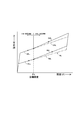
- FIG. 2 is a pedaling force characteristic diagram showing a pedaling force that forms a hysteresis generated by a hysteresis generating mechanism included in the accelerator pedal device shown in FIG. 1.
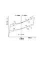
- FIG. 6 is a pedaling force characteristic diagram showing a first embodiment in which a reaction force is added by a reaction force adding mechanism to the pedaling force having the hysteresis shown in FIG. 5.
- FIG. 6 is a pedaling force characteristic diagram showing a second embodiment in which a reaction force is added by a reaction force adding mechanism to the pedaling force having the hysteresis shown in FIG. 5.
- FIG. 6 is a pedaling force characteristic diagram showing a third embodiment in which a reaction force is added by a reaction force adding mechanism to the pedaling force having the hysteresis shown in FIG. 5.
- FIG. 6 is a pedaling force characteristic diagram showing a first embodiment in which a reaction force is added by a reaction force adding mechanism to the pedaling force having the hysteresis shown in FIG. 5.
- FIG. 6 is a pedaling force characteristic diagram showing a second embodiment in which a reaction force is added by a reaction force adding mechanism to the pedaling force having the hysteresis shown
- FIG. 9 is a pedaling force characteristic diagram showing a modified example of the third embodiment in which a reaction force is added by a reaction force adding mechanism to the pedaling force having the hysteresis shown in FIG. 5.
- FIG. 12 is a pedaling force characteristic diagram showing another modified example of the third embodiment in which the reaction force is added by the reaction force adding mechanism to the pedaling force having the hysteresis shown in FIG. 5.
- FIG. 12 is a pedaling force characteristic diagram showing still another modified example of the third embodiment in which the reaction force is added by the reaction force adding mechanism to the pedaling force having the hysteresis shown in FIG. 5.
- an accelerator pedal device includes a housing 10 fixed to a vehicle body such as an automobile, an accelerator pedal 20, a return spring 30, a hysteresis generation mechanism 40, and a position sensor 50. , A reaction force adding mechanism 60 and a control unit 70.
- the housing 10 is made of a resin material and includes a support shaft 11, a housing portion 12, a housing portion 13, a buried portion 14, and a housing portion 15.
- the support shaft 11 is formed in a cylindrical shape around the axis S, and supports the accelerator pedal 20 swingably around the axis S when the accelerator pedal 20 is depressed or returned.
- the housing 12 houses a part of the return spring 30 and the reaction force applying mechanism 60 in the housing 10.
- the housing portion 13 houses the hysteresis generating mechanism 40 in the housing 10.
- the embedding part 14 embeds a part of the position sensor 50 around the axis S.
- the accommodating portion 15 accommodates the control unit 70 that is electrically connected to the outside in the upper region of the housing 10.
- the accelerator pedal 20 is entirely formed of a resin material, and includes a cylindrical portion 21, a lower arm portion 22, an upper arm portion 23, and a pedal portion 24, as shown in FIGS. 1 to 3.
- the cylindrical portion 21 is fitted to the support shaft 11 of the housing 10 and is rotatably supported.
- the lower arm portion 22 extends downward from the cylindrical portion 21 and is integrally formed.
- the upper arm portion 23 is integrally formed by extending upward from the cylindrical portion 21, and engages with the first slider 41 of the hysteresis generating mechanism 40, the return lever 62 of the reaction force adding mechanism 60, and the return spring 30.
- the pedal portion 24 is integrally formed in a lower region of the lower arm portion 22.
- the return spring 30 is a compression-type coil spring formed of spring steel or the like, and one end of the return spring 30 engages with the inner wall of the housing 10 and the other end of the return spring 30 has an upper arm 23 of the accelerator pedal 20. It is arranged in a compressed state by being engaged with the cylinder portion 21 side. Then, the return spring 30 exerts a biasing force that returns the accelerator pedal 20 to the rest position.
- the hysteresis generating mechanism 40 includes a first slider 41, a second slider 42, and a biasing spring 43.
- the first slider 41 is made of a resin material, for example, a highly slidable material such as oil-impregnated polyacetal, and has a contact surface 41a slidably contacting the lower inner wall surface 13a of the housing 10 and an inclined surface of the second slider 42.
- the upper surface 23a of the upper arm 23 has a slanting surface 41b that contacts with 42b, and an engaging surface 41c with which the upper end 23a of the upper arm 23 is detachably engaged.
- the second slider 42 is made of a resin material, for example, a highly slidable material such as oil-impregnated polyacetal, and has a contact surface 42a slidably contacting the upper inner wall surface 13b of the housing 10 and an inclined surface 41b of the first slider 41. And a receiving surface 42c that receives one end of the biasing spring 43.
- the urging spring 43 is a compression type coil spring formed of, for example, spring steel, one end of which is engaged with the receiving surface 42c of the second slider 42, and the other end of which is engaged with the inner wall 13c of the housing 10. It is placed in a compressed state.
- the biasing spring 43 presses the inclined surface 42b of the second slider 42 against the inclined surface 41b of the first slider 41 to move the first slider 41 and the second slider 42 to the lower inner wall surface 13a and the upper inner wall surface 13b.
- a wedge action is exerted so that the accelerator pedal 20 is pressed toward, and an urging force that returns the accelerator pedal 20 to the rest position is exerted via the first slider 41 and the second slider 42.
- the accelerator pedal 20 is depressed from the rest position toward the maximum depression position against the urging force of the return spring 30 and the urging spring 43, the upper arm portion 23 resists the urging force of the urging spring 43. Then, the first slider 41 is pressed leftward in FIG. At the time of this stepping operation, the first slider 41 and the second slider 42 exert a wedge action on each other due to the biasing force exerted by the biasing spring 43, and a frictional force (sliding resistance) is generated on the housing 10.
- the frictional force at the time of the stepping operation acts in a direction opposing the stepping operation and increases as the amount of compression of the biasing spring 43 increases.
- the stepping force at the time of stepping is higher than the stepping force line DNL on the upper side of the hysteresis stepping force line NL shown in FIG. And increases linearly with an increase in the depression amount (opening of the accelerator pedal).
- the pedaling force at the time of returning is as shown in the hysteresis pedaling force line NL in FIG. It is shown as the lower tread force line RNL, and decreases linearly with a decrease in the depression amount (accelerator pedal opening).
- the position sensor 50 functions as a detection sensor that detects the operation of the accelerator pedal 20, and is also referred to as an APS (accelerator position sensor). In the region around the axis S, the position sensor 50 has a cylindrical portion 21 of the accelerator pedal 20 and the housing 10.
- the position sensor 50 disposed in the embedded portion 14 is, for example, a non-contact magnetic sensor, and as shown in FIGS. 2 and 3, an annular armature 51, a pair of permanent magnets 52, two stators 53, It is composed of two Hall elements 54.
- the armature 51 is formed of a magnetic material in an annular shape and is embedded in the inner peripheral surface of the cylindrical portion 21 of the accelerator pedal 20.
- the pair of permanent magnets 52 are formed in an arc shape and are joined to the inner peripheral surface of the armature 51.
- the two stators 53 are formed of a magnetic material and are embedded in the embedded portion 14 of the housing 10.
- the two Hall elements 54 are arranged between the two stators 53 and are embedded in the embedded portion 14 of the housing 10. As other related components, a terminal and a circuit board on which various electronic components are mounted are embedded in the embedded portion 14.
- the position sensor 50 detects a change in the magnetic flux density caused by the rotation of the accelerator pedal 20 with the hall element 54 and outputs it as a voltage signal. That is, the position sensor 50 can detect the opening position of the accelerator pedal 20, and whether the accelerator pedal 20 is in a depressing operation or a returning operation or an operation of a driver who operates the accelerator pedal 20. The force can be detected by the rate of change of the voltage signal.
- the reaction force adding mechanism 60 includes a torque motor 61 and a return lever 62 directly connected to the torque motor 61.
- the torque motor 61 includes a rotor 61a that has a magnet and rotates about the axis S2, a yoke 61b that forms a magnetic path around the rotor 61a, and an exciting coil 61c that is wound around the yoke 61b.
- the rotor 61 a of the torque motor 61 and the return lever 62 are arranged in the housing portion 12 of the housing 10.
- the torque motor 61 rotates the return lever 62 integrally with the rotor 61a so that the return lever 62 reciprocates within a predetermined angle range around the axis S2.
- the torque motor 61 generates a constant rotational torque when the supplied drive current is constant, and when the supplied drive current linearly increases, the generated rotational torque linearly increases. ing. That is, when the torque motor 61 is drive-controlled, the magnitude of the drive current supplied is adjusted according to the opening degree ⁇ of the accelerator pedal 20.
- the return lever 62 is directly connected to the rotor 61a of the torque motor 61 that rotates about the axis S2, and the tip portion thereof is detachably engaged with the intermediate portion of the upper arm portion 23 of the accelerator pedal 20. To do.
- the return lever 62 When the torque motor 61 is not energized and exerts no rotation torque, the return lever 62 is always engaged with the upper arm portion 23 by the magnetic spring and follows the swing of the accelerator pedal 20. ..
- the magnetic spring tries to return the rotor to the original neutral position by the action of the magnetic flux changed in the magnetic circuit when the rotor is forcibly rotated from the neutral position where the rotor stops when not energized. It is torque.
- the neutral position corresponds to the rest position of the accelerator pedal 20.
- the torque motor 61 when the torque motor 61 is energized to generate a rotational torque, the return lever 62 resists the pedaling force and applies a reaction force in the direction of pushing back the accelerator pedal 20.
- the control unit 70 is arranged in the housing portion 15 located above the housing 10.
- the control unit 70 includes a control unit 71, a drive circuit 72, a current detection circuit 73, an interface circuit 74, a power supply circuit 75, a reference voltage input circuit 76, and an APS signal input circuit 77.
- the control unit 70, the ECU 80, the mode changeover switch 90, and the battery 100 respectively mounted on the vehicle constitute the entire control system.
- the control unit 71 is a microcomputer or the like that controls various controls in the accelerator pedal device, and controls the driving of the torque motor 61 based on a command signal issued from the ECU 80.
- the control unit 71 corresponds in advance to a map associating the drive current value of the torque motor 61 with the generated torque, a map associating various driving states of the vehicle with the opening degree of the accelerator pedal 20, and various driving modes.
- Information about a plurality of target opening degrees of the accelerator pedal 20, preset, a map associating the opening degree of the accelerator pedal 20 with the rotation angle of the torque motor 61, and other various information are stored as necessary.
- the control unit 71 performs arithmetic processing and determination processing based on the command signal issued from the ECU 80, various maps and information, and drives and controls the torque motor 61.
- the drive circuit 72 drives the torque motor 61 by the PWM signal based on the control signal of the control unit 71.
- the current detection circuit 73 detects the actual current value flowing through the torque motor 61.
- the interface circuit 74 transmits/receives signals between the control unit 71 and the ECU 80 by CAN communication (controller area network).
- the power supply circuit 75 guides the power supply to the control unit 71.
- the reference voltage input circuit 76 inputs the reference voltage of the position sensor 50 to the control unit 71.
- the APS signal input circuit 77 inputs the output signal of the position sensor 50 to the control unit 71.
- the ECU 80 controls the entire vehicle, and outputs a command signal calculated based on a control map stored in advance based on a driving state of the vehicle and an output signal from the mode changeover switch 90 via CAN communication. Output to the control unit 71.
- the control map is, for example, a map in which the engine speed, the vehicle speed, the load, the gear shift state of the transmission, the distance to the preceding vehicle, the road surface information, the driving mode, and the accelerator opening degree are associated with each other.
- the driving mode includes a normal drive mode, an eco-drive mode, a sports drive mode, and the like.
- the mode changeover switch 90 is provided on the vehicle and can be turned on/off by a driver's operation.
- the driver turns on the mode changeover switch 90, for example, the eco-drive mode is selected, and when the mode changeover switch 90 is turned off, the normal drive mode is selected.
- the mode switch 90 may be set so as to select a plurality of driving modes including a normal drive mode, an eco-drive mode, a sports drive mode, and the like.
- the calculation unit 71 or the ECU 80 determines the opening degree of the accelerator pedal 20, the operation direction of the stepping operation and the returning operation as necessary, or the driver's operation force based on the output signal of the position sensor 50.
- the calculation process and the determination process for determining the size are executed. Further, since the torque motor 61 rotates in conjunction with the opening degree of the accelerator pedal 20, the control unit 70 drives and controls the torque motor 61 based on the information from the position sensor 50.
- the control unit 70 when the accelerator pedal 20 is stepped on, the control unit 70, based on the information about the operating state of the vehicle, etc., has an accelerator pedal with a target opening degree ⁇ t preset corresponding to the operating state.
- the reaction force adding mechanism 60 is drive-controlled so as to add a reaction force such that 20 is maintained. That is, the control unit 70 determines that the change rate ( ⁇ N/ ⁇ ) of the pedal effort in the opening region larger than the target opening ⁇ t is the target opening ⁇ t with the predetermined target opening ⁇ t at which the accelerator pedal 20 is depressed as a boundary.
- the reaction force applying mechanism 60 is drive-controlled so that the reaction force adding mechanism 60 is relatively larger than the change rate ( ⁇ N/ ⁇ ) of the pedaling force in a smaller opening region.
- the driver receives the pedaling force along the pedaling force line RNL in FIG. 5, while the accelerator pedal 20 is rotated clockwise in FIG. 3 by the urging force of the return spring 30. It rotates and stops at the rest position.
- the return lever 62 follows the movement of the accelerator pedal 20 without applying a reaction force when the torque motor 61 is not energized.
- the control unit 70 applies a reaction force that gradually decreases as the opening degree ⁇ of the accelerator pedal 20 increases in an opening degree region smaller than the target opening degree ⁇ t. In order to do so, the reaction force adding mechanism 60 is drive-controlled.
- a command signal is issued from the ECU 80 to the control unit 71 via the interface circuit 74 based on the ON operation.
- the target opening ⁇ t is set so as to correspond to the accelerator opening in the eco-drive mode.
- the control unit 71 executes various calculation processes and determination processes based on the command signal of the ECU 80, the output signal of the position sensor 50, etc., and controls the drive current supplied to the torque motor 61 via the drive circuit 72. Control size appropriately.
- the control unit 70 is configured to drive and control the reaction force adding mechanism 60 in conjunction with the ON operation of the mode changeover switch 90.
- the rate of change ⁇ N/ ⁇ of the pedal effort (pedal force line DNL) in the opening region larger than the target opening ⁇ t is smaller than the target opening ⁇ t (pedal force).
- the reaction force adding mechanism 60 is drive-controlled so as to be relatively larger than the rate of change ⁇ N/ ⁇ of the line DAL).
- the driver can smoothly step on the target opening degree ⁇ t, and since the driver feels that the pedaling force N gradually increases with the target opening degree ⁇ t as an inflection point. As a result, there is no occurrence of a feeling of discomfort or fatigue caused by the accelerator pedal returning operation due to a sudden change as in the conventional case. Therefore, the driver can easily recognize the target opening ⁇ t corresponding to the inflection point, and can easily maintain the accelerator pedal 20 at the target opening ⁇ t.
- the return lever 62 can be detached from the upper arm portion 23 of the accelerator pedal 20, so that the accelerator pedal 20 can surely return to the rest position. .. Further, even if the hysteresis generation mechanism 40 malfunctions, the return spring 30 directly applies the urging force to the accelerator pedal 20, so that the accelerator pedal 20 can surely return to the rest position.
- the control unit 70 applies a reaction force that gradually increases as the opening ⁇ of the accelerator pedal 20 increases in an opening region larger than the target opening ⁇ t.
- the reaction force adding mechanism 60 is drive-controlled.
- the calculation process and the determination process of the control unit 71 based on the ON/OFF operation of the mode changeover switch 90 by the driver are the same as those in the first embodiment described above, and thus the description thereof will be omitted.
- the reaction force is added to the pedaling force N in an opening region smaller than the target opening ⁇ t and in the target opening ⁇ t. It is not the normal pedaling force line DNL but the pedaling force line DAL to which the reaction force that gradually increases as the opening degree of the accelerator pedal 20 increases is added in the opening area larger than the target opening degree ⁇ t.
- the torque motor 61 is drive-controlled. At this time, the drive current supplied to the torque motor 61 is controlled so as to gradually increase from the target opening ⁇ t as the opening of the accelerator pedal 20 increases. In the state where such a reaction force is applied, when the accelerator pedal 20 is returned, the pedaling force N is larger than the normal pedaling force line RNL in the opening region larger than the target opening degree ⁇ t. Becomes
- the rate of change ⁇ N/ ⁇ of the pedal effort (pedal force line DAL) in the opening area larger than the target opening ⁇ t is smaller than the target opening ⁇ t.
- the reaction force adding mechanism 60 is drive-controlled so that the change rate ⁇ N/ ⁇ of the line DNL) becomes relatively larger.
- the driver By controlling the pedal effort characteristic in this way, when the driver steps on to the target opening degree ⁇ t, the driver receives the sensation that the pedal effort N gradually increases with the target opening degree ⁇ t as an inflection point. Accelerator pedal return movements, operational discomfort, and fatigue will not occur. Therefore, the driver can easily recognize the target opening ⁇ t corresponding to the inflection point, and can easily maintain the accelerator pedal 20 at the target opening ⁇ t.
- the control unit 70 applies a reaction force that gradually decreases as the opening ⁇ of the accelerator pedal 20 increases in an opening region smaller than the target opening ⁇ t. Further, the reaction force adding mechanism 60 is drive-controlled so as to add a reaction force that gradually increases as the opening degree ⁇ of the accelerator pedal 20 increases in an opening degree region larger than the target opening degree ⁇ t.
- the calculation process and the determination process of the control unit 71 based on the ON/OFF operation of the mode changeover switch 90 by the driver are the same as those in the first embodiment described above, and thus the description thereof will be omitted.
- the pedal effort N gradually increases toward the target opening ⁇ t in an opening region smaller than the target opening ⁇ t.
- the pedal force line DAL becomes larger than the normal pedal force line DNL to which the smaller reaction force is added, and the normal pedal force line DNL to which the reaction force is not added is obtained at the target opening ⁇ t, and the opening region is larger than the target opening ⁇ t.
- the torque motor 61 is drive-controlled so that the pedal effort line DAL is provided with a reaction force that gradually increases as the opening degree ⁇ of the accelerator pedal 20 increases.
- the drive current supplied to the torque motor 61 gradually decreases from a predetermined value as the opening of the accelerator pedal 20 increases, becomes zero at the target opening ⁇ t, and exceeds the target opening ⁇ t. Therefore, it is controlled so as to gradually increase as the opening degree of the accelerator pedal 20 increases.
- the pedal effort N is larger than the normal pedal effort line RNL in the opening region larger than the target opening ⁇ t.
- the pedal effort line RAL is larger than the normal pedal effort line RNL.
- the rate of change ⁇ N/ ⁇ of the pedal effort (pedal force line DAL) in the opening area larger than the target opening ⁇ t is smaller than the target opening ⁇ t.
- the reaction force adding mechanism 60 is drive-controlled so that the change rate ⁇ N/ ⁇ of the line DNL) becomes relatively larger.
- the driver can smoothly step to the target opening ⁇ t, and when stepping to the target opening ⁇ t, the pedaling force N is changed with the target opening ⁇ t as an inflection point. Since the user feels a gradual increase, there is no possibility of the accelerator pedal returning operation, the discomfort in operation, or the feeling of fatigue that would otherwise occur due to a sudden change. Therefore, the driver can easily recognize the target opening ⁇ t corresponding to the inflection point, and can easily maintain the accelerator pedal 20 at the target opening ⁇ t.
- the target opening ⁇ t can be appropriately selected within the operating range of the accelerator pedal 20, as shown by the arrow in FIG. 9. That is, as the target opening degree ⁇ t, a plurality of target opening degrees ⁇ t are set in advance corresponding to various driving states of the vehicle, and the control unit 70 sends a command signal based on the driving state of the vehicle issued from the ECU 80.
- the reaction force adding mechanism 60 can be drive-controlled based on the corresponding target opening degree ⁇ t.
- the reaction force adding mechanism 60 is drive-controlled according to the plurality of target opening degrees ⁇ t, so that the driving environment such as high-speed cruising operation on a highway or the like, low-speed operation in a city or the like, or a plurality of driving operations.
- the driver can easily recognize each target opening degree ⁇ t and easily maintain the accelerator pedal 20 at the target opening degree ⁇ t, so that the driver can perform optimal driving without feeling fatigue or annoyance. It can be carried out.
- the pedaling force N (pedaling force line DAL) when the reaction force is applied can be appropriately set within the range shown by the chain double-dashed line in FIG. 10. That is, the control unit 70 drives and controls the reaction force adding mechanism 60 so as to apply the reaction force so that the rate of change ⁇ N/ ⁇ of the pedaling force N becomes a magnitude corresponding to the operating force of the driver who operates the accelerator pedal 20. To do. Even in this drive control, the control unit 70 sets the change rate ⁇ N/ ⁇ of the pedaling force N in the opening region larger than the target opening ⁇ t at the boundary of the predetermined target opening ⁇ t at which the accelerator pedal is depressed. It is premised that the reaction force adding mechanism 60 is drive-controlled so as to be relatively larger than the change rate ⁇ N/ ⁇ of the pedaling force N in an opening area smaller than the target opening ⁇ t.
- the ECU 80 or the controller 71 determines whether the driver has a large operating force (stepping force) when the rate of change is large. If it is an operation and the change rate is small, it is determined that the operation is performed by a driver having a small operation force. Then, the control unit 71 drives and controls the reaction force adding mechanism 60 based on a previously stored control map or the like so that the rate of change ⁇ N/ ⁇ of the pedaling force N corresponding to each operating force is set.
- the operating force of the driver differs depending on the physique and sex, and the way the pedal force is felt differs for each driver. Therefore, as shown in FIG. 10, the driving control is performed so that the pedaling characteristics are optimal according to the driver. It does not cause a feeling of strangeness or fatigue during operation. Therefore, the driver can easily recognize the target opening ⁇ t corresponding to the inflection point, and can easily maintain the accelerator pedal 20 at the target opening ⁇ t.
- the control unit 70 drives and controls the reaction force adding mechanism 60 so as not to apply the reaction force at the target opening degree ⁇ t
- the reaction force is added at the target opening degree ⁇ t.
- a reaction force that gradually decreases toward the target opening ⁇ t is added to the pedaling force N in an opening region smaller than the target opening ⁇ t.
- the pedaling force line DAL is larger than the normal pedaling force line DNL to which a predetermined amount of reaction force is added at the target opening degree ⁇ t, and the opening degree ⁇ of the accelerator pedal 20 is increased in the opening region larger than the target opening degree ⁇ t.
- the torque motor 61 is drive-controlled so that the pedal force line DAL is applied with a reaction force that gradually increases as a result. At this time, the drive current supplied to the torque motor 61 gradually decreases from a predetermined magnitude to the target opening ⁇ t as the opening of the accelerator pedal 20 increases. It is controlled so as to gradually increase as the opening degree of 20 increases.
- the rate of change ⁇ N/ ⁇ of the pedal effort (pedal force line DAL) in the opening area larger than the target opening ⁇ t is smaller than the target opening ⁇ t.
- the reaction force adding mechanism 60 is drive-controlled so that the change rate ⁇ N/ ⁇ of the line DNL) becomes relatively larger.
- the driver can smoothly step on to the target opening ⁇ t and can step on to the target opening ⁇ t while feeling that the pedaling force has increased slightly over the entire area. Since the pedaling force N gradually increases with the target opening ⁇ t as an inflection point, the accelerator pedal returning operation, the discomfort in operation, and the feeling of fatigue do not occur due to a rapid change as in the related art. Therefore, the driver can easily recognize the target opening ⁇ t corresponding to the inflection point while feeling a certain amount of load, and can easily maintain the accelerator pedal 20 at the target opening ⁇ t.
- reaction force addition mechanism 60 including the torque motor 61 is shown as the reaction force addition mechanism, but the present invention is not limited to this, and a reaction force may be added in the direction in which the accelerator pedal 20 is pushed back. Other mechanisms may be adopted as long as they can be controlled.
- the hysteresis generating mechanism is the hysteresis generating mechanism 40 including the first slider 41, the second slider 42, and the biasing spring 43.
- the hysteresis generating mechanism is not limited to this, and the hysteresis force generating mechanism 40 is not limited to this.
- Other mechanisms may be adopted as long as they generate hysteresis.
- control unit 70 drives and controls the reaction force addition mechanism 60 in conjunction with the ON operation of the mode changeover switch 90, and the control unit 70 causes the reaction force addition mechanism in conjunction with the OFF operation of the mode changeover switch 90.
- canceling the drive control of 60 is shown, it is not limited to this, and conversely, the control unit 70 cancels the drive control of the reaction force adding mechanism 60 in conjunction with the ON operation of the mode changeover switch 90.
- a configuration may be adopted in which the control unit 70 drives and controls the reaction force adding mechanism 60 in conjunction with the OFF operation of the mode changeover switch 90.
- the accelerator pedal 20 swingably supported by the support shaft 11 of the housing 10 is shown as the accelerator pedal, but the present invention is not limited to this.
- the accelerator pedal is swingably supported on the floor of the vehicle, or the pedal arm is swingably supported by a support shaft of the housing and is swingably supported on the floor of the vehicle.
- the accelerator pedal device of the present invention can easily recognize the preset target opening degree according to the driving state, can easily maintain the target opening degree, and when applying the reaction force. Since it is possible to obtain excellent operability that does not cause the driver to feel uncomfortable, it is not only applicable to automobiles and the like, but also useful for work vehicles and other vehicles.
Landscapes
- Engineering & Computer Science (AREA)
- Physics & Mathematics (AREA)
- General Physics & Mathematics (AREA)
- Automation & Control Theory (AREA)
- Chemical & Material Sciences (AREA)
- Combustion & Propulsion (AREA)
- Transportation (AREA)
- Mechanical Engineering (AREA)
- Auxiliary Drives, Propulsion Controls, And Safety Devices (AREA)
- Control Of Throttle Valves Provided In The Intake System Or In The Exhaust System (AREA)
Abstract
Description
また、アクセル開度減少時に、閾値よりも小さいアクセル開度においてステップ的に増加した踏力を解除して、急激な踏力の増加に伴うアクセルペダルのバタツキを防止するように設定されている。
また、反力の急激な増加により、運転者は、ペダルの重さを感じ、その状態が続くと足の疲労感を招く虞がある。
一実施形態に係るアクセルペダル装置は、図1ないし図4に示すように、車両としての自動車等の車体に固定されるハウジング10、アクセルペダル20、戻しバネ30、ヒステリシス発生機構40、位置センサ50、反力付加機構60、制御ユニット70を備えている。
支軸11は、軸線Sを中心とする円柱状に形成され、アクセルペダル20の踏込み操作及び戻し操作において、アクセルペダル20を軸線S回りに揺動自在に支持する。
収容部12は、ハウジング10内において、戻しバネ30及び反力付加機構60の一部を収容する。
収容部13は、ハウジング10内において、ヒステリシス発生機構40を収容する。
埋設部14は、軸線Sの周りにおいて位置センサ50の一部を埋設する。
収容部15は、ハウジング10の上方領域において、外部との電気接続を行う制御ユニット70を収容する。
円筒部21は、ハウジング10の支軸11に嵌合されて回動自在に支持される。
下側アーム部22は、円筒部21から下方に伸長して一体的に形成されている。
上側アーム部23は、円筒部21から上方に伸長して一体的に形成され、ヒステリシス発生機構40の第1スライダ41及び反力付加機構60の戻しレバー62並びに戻しバネ30と係合する。
ペダル部24は、下側アーム部22の下方領域に一体的に形成されている。
そして、戻しバネ30は、アクセルペダル20を休止位置に戻す付勢力を及ぼす。
第1スライダ41は、樹脂材料、例えば、含油ポリアセタール等の高摺動性材料により形成され、ハウジング10の下側内壁面13aに摺動自在に接触する接触面41a、第2スライダ42の傾斜面42bと接触する傾斜面41b、上側アーム部23の上端部23aが離脱可能に係合し得る係合面41cを有する。
第2スライダ42は、樹脂材料、例えば、含油ポリアセタール等の高摺動性材料により形成され、ハウジング10の上側内壁面13bに摺動自在に接触する接触面42a、第1スライダ41の傾斜面41bと接触する傾斜面42b、付勢バネ43の一端部を受ける受け面42cを有する。
付勢バネ43は、例えばバネ鋼等により形成された圧縮型のコイルバネであり、一端部が第2スライダ42の受け面42cに係合し、他端部がハウジング10の内壁13cに係合して圧縮された状態で配置される。
この踏込み操作のとき、付勢バネ43が及ぼす付勢力により、第1スライダ41及び第2スライダ42が互いにくさび作用を及ぼし、ハウジング10に対して摩擦力(摺動抵抗)が生じる。踏込み操作時の摩擦力は、踏込み操作と対抗する向きに作用すると共に付勢バネ43の圧縮量の増加に伴って増加する。
したがって、踏込み操作時の摩擦力と踏込み操作に応じて増加する付勢バネ43の付勢力との合力により、踏込み時の踏力は、図5のヒステリシスをなす踏力線NLにおいて、上側の踏力線DNLとして示され、踏込み量(アクセルペダルの開度)の増加に伴って直線的に増加する。
この戻し操作のときも、付勢バネ43が及ぼす付勢力により、第1スライダ41及び第2スライダ42が互いにくさび作用を及ぼし、ハウジング10に対して摩擦力(摺動抵抗)が生じる。戻し操作時の摩擦力は、踏込み操作の場合と逆向きに作用すると共に付勢バネ43の圧縮量の減少に伴って減少する。
したがって、逆向きに作用する戻し操作時の摩擦力と戻し操作に応じて減少する付勢バネ40の付勢力との合力により、戻し時の踏力は、図5のヒステリシスをなす踏力線NLにおいて、下側の踏力線RNLとして示され、踏込み量(アクセルペダルの開度)の減少に伴って直線的に減少する。
尚、戻し操作の途中において、第1スライダ41がスティックして停止したときは、戻しバネ30の付勢力により、上側アーム部23が第1スライダ41から離脱することで、アクセルペダル20は休止位置に戻る。
位置センサ50は、例えば非接触式の磁気式センサであり、図2及び図3に示すように、環状のアマチャ51、一対の永久磁石52、二つのステータ53、二つのホール素子54により構成されている。
一対の永久磁石52は、円弧状に形成され、アマチャ51の内周面に結合されている。
二つのステータ53は、磁性材料により形成され、ハウジング10の埋設部14に埋設されている。
二つのホール素子54は、二つのステータ53の間に配置されて、ハウジング10の埋設部14に埋設されている。
その他に関連する部品として、端子、種々の電子部品が実装された回路基板が、埋設部14に埋設されている。
トルクモータ61は、磁石を有し軸線S2回りに回転するロータ61a、ロータ61aの周りに磁路を形成するヨーク61b、ヨーク61bに巻回された励磁用のコイル61cを備えている。
そして、トルクモータ61のロータ61a及び戻しレバー62が、ハウジング10の収容部12に配置されている。
ここで、トルクモータ61は、供給される駆動電流が一定のとき一定の回転トルクを発生し、供給される駆動電流が直線的に増加すると、発生する回転トルクが直線的に増加するようになっている。
すなわち、トルクモータ61は、駆動制御される際に、アクセルペダル20の開度θに応じて、供給される駆動電流の大きさが調整されるようになっている。
戻しレバー62は、図3に示すように、軸線S2を中心に回動するトルクモータ61のロータ61aに直結され、先端部がアクセルペダル20の上側アーム部23の中間部に離脱可能に係合する。
ここで、磁気スプリングとは、ロータが非通電時に停止する中立位置から強制的に回転させられたとき、磁気回路内で変化した磁束の作用により、元の中立位置にロータを復帰させようとするトルクである。当該中立位置は、アクセルペダル20の休止位置に対応している。
一方、トルクモータ61が通電されて回転トルクを発生するとき、戻しレバー62は、踏力に抵抗してアクセルペダル20を押し戻す方向に反力を付加するようになっている。
制御ユニット70は、図4に示すように、制御部71、駆動回路72、電流検出回路73、インターフェース回路74、電源回路75、基準電圧入力回路76、APS信号入力回路77を備えている。
そして、上記のアクセルペダル装置が車両に搭載された状態において、制御ユニット70、車両にそれぞれ搭載されたECU80及びモード切替スイッチ90並びにバッテリ100により、全体の制御システムが構成されている。
また、制御部71には、予め、トルクモータ61の駆動電流値と発生トルクとを関連付けるマップ、車両の種々の運転状態とアクセルペダル20の開度とを関連付けるマップ、種々の運転モードに対応して予め設定されたアクセルペダル20の複数の目標開度に関する情報、アクセルペダル20の開度とトルクモータ61の回転角度とを関連付けるマップ、その他必要に応じて種々の情報が記憶されている。
そして、制御部71は、ECU80から発せられる指令信号、種々のマップ及び情報に基づいて演算処理及び判定処理を行い、トルクモータ61を駆動制御する。
電流検出回路73は、トルクモータ61を流れる実際の電流値を検出する。
インターフェース回路74は、制御部71とECU80との間で、CAN通信(コントローラ・エリア・ネットワーク)により信号の送受信を行う。
電源回路75は、制御部71に電源を導く。
基準電圧入力回路76は、位置センサ50の基準電圧を制御部71に入力する。
APS信号入力回路77は、位置センサ50の出力信号を制御部71に入力する。
ここで、制御マップとしては、例えば、エンジンの回転数、車速、負荷、トランスミッションの変速状態、前方車両との距離、路面情報、運転モードと、アクセル開度とを関連付けるマップ等である。
ここで、運転モードとしては、通常ドライブモード、エコドライブモード、スポーツドライブモード等が含まれる。
運転者が、モード切替スイッチ90をオンにすると、例えば、エコドライブモードが選択され、モード切替スイッチ90をオフにすると、通常のドライブモードが選択されるように設定される。
尚、モード切替スイッチ90は、通常ドライブモード、エコドライブモード、スポーツドライブモード等を含む複数の運転モードを選択できるように設定されてもよい。
また、トルクモータ61はアクセルペダル20の開度に連動して回動するため、位置センサ50の情報に基づいて、制御ユニット70はトルクモータ61を駆動制御する。
すなわち、制御ユニット70は、アクセルペダル20が踏込まれた所定の目標開度θtを境にして、目標開度θtよりも大きい開度領域における踏力の変化率(ΔN/Δθ)が目標開度θtよりも小さい開度領域における踏力の変化率(ΔN/Δθ)よりも相対的に大きくなるように、反力付加機構60を駆動制御するようになっている。
先ず、アクセルペダル20が操作されないとき、アクセルペダル20は、戻しバネ30の付勢力により、休止位置に停止している。
この踏込み操作において、戻しレバー62は、トルクモータ61が非通電の状態で反力を付加することなくアクセルペダル20の移動に追従する。
この戻し操作において、戻しレバー62は、トルクモータ61が非通電の状態で反力を付加することなくアクセルペダル20の移動に追従する。
第1実施形態では、図6に示すように、制御ユニット70は、目標開度θtよりも小さい開度領域において、アクセルペダル20の開度θの増加に伴って徐々に小さくなる反力を付加するべく、反力付加機構60を駆動制御する。
そして、制御部71は、ECU80の指令信号及び位置センサ50の出力信号等に基づいて、種々の演算処理及び判定処理を実行し、駆動回路72を介して、トルクモータ61に供給する駆動電流の大きさを適宜制御する。
ここでは、制御ユニット70は、モード切替スイッチ90のオン操作に連動して、反力付加機構60を駆動制御するようになっている。
このとき、トルクモータ61に供給される駆動電流は、アクセルペダル20の開度の増加に伴って、所定の大きさから徐々に小さくなり、目標開度θtにおいて零となるように制御される。
このような反力が付加された状態において、アクセルペダル20の戻し操作の際には、目標開度θtよりも小さい開度領域において、踏力Nは、通常の踏力線RNLよりも大きい踏力線RALとなる。
したがって、運転者は、変曲点に対応する目標開度θtを容易に認識でき、アクセルペダル20を目標開度θtに容易に維持することができる。
そして、制御ユニット70による反力付加機構60の駆動制御は解除される。これにより、アクセルペダル20の踏力Nは、図5に示す通常の踏力線DNL,RNLとなる。
第2実施形態では、図7に示すように、制御ユニット70は、目標開度θtよりも大きい開度領域において、アクセルペダル20の開度θの増加に伴って徐々に大きくなる反力を付加するべく、反力付加機構60を駆動制御する。
尚、運転者によるモード切替スイッチ90のオン/オフ操作に基づく制御部71の演算処理及び判定処理等は前述の第1実施形態と同様であるため、説明を省略する。
このとき、トルクモータ61に供給される駆動電流は、目標開度θtからアクセルペダル20の開度の増加に伴って徐々に大きくなるように制御される。
このような反力が付加された状態において、アクセルペダル20の戻し操作の際には、目標開度θtよりも大きい開度領域において、踏力Nは、通常の踏力線RNLよりも大きい踏力線RALとなる。
したがって、運転者は、変曲点に対応する目標開度θtを容易に認識でき、アクセルペダル20を目標開度θtに容易に維持することができる。
第3実施形態では、図8に示すように、制御ユニット70は、目標開度θtよりも小さい開度領域においてアクセルペダル20の開度θの増加に伴って徐々に小さくなる反力を付加し、かつ、目標開度θtよりも大きい開度領域においてアクセルペダル20の開度θの増加に伴って徐々に大きくなる反力を付加するべく、反力付加機構60を駆動制御する。
尚、運転者によるモード切替スイッチ90のオン/オフ操作に基づく制御部71の演算処理及び判定処理等は前述の第1実施形態と同様であるため、説明を省略する。
このとき、トルクモータ61に供給される駆動電流は、アクセルペダル20の開度の増加に伴って所定の大きさから徐々に小さくなり、目標開度θtにおいて零となり、目標開度θtを超えてからアクセルペダル20の開度の増加に伴って徐々に大きくなるように制御される。
このような反力が付加された状態において、アクセルペダル20の戻し操作の際には、踏力Nは、目標開度θtよりも大きい開度領域において、通常の踏力線RNLよりも大きい踏力線RALとなり、目標開度θtよりも小さい開度領域において、通常の踏力線RNLよりも大きい踏力線RALとなる。
したがって、運転者は、変曲点に対応する目標開度θtを容易に認識でき、アクセルペダル20を目標開度θtに容易に維持することができる。
すなわち、目標開度θtとして、車両の種々の運転状態に対応して、予め複数の目標開度θtが設定されており、制御ユニット70は、ECU80から発せられる車両の運転状態に基づく指令信号に対応する目標開度θtに基づいて、反力付加機構60を駆動制御することができる。
すなわち、制御ユニット70は、踏力Nの変化率ΔN/Δθがアクセルペダル20を操作する運転者の操作力に応じた大きさとなるように反力を付加するべく、反力付加機構60を駆動制御する。
尚、この駆動制御においても、制御ユニット70は、アクセルペダルが踏込まれた所定の目標開度θtを境にして、目標開度θtよりも大きい開度領域における踏力Nの変化率ΔN/Δθが、目標開度θtよりも小さい開度領域における踏力Nの変化率ΔN/Δθよりも相対的に大きくなるように反力付加機構60を駆動制御する、ことが前提となる。
そして、制御部71が、予め記憶された制御マップ等に基づき、それぞれの操作力に対応した踏力Nの変化率ΔN/Δθとなるように、反力付加機構60を駆動制御する。
したがって、図10に示すように、運転者に応じた最適な踏力特性となるように駆動制御されることにより、いずれの運転者においても、従来のような急激な変化によるアクセルペダルの戻し動作、操作上の違和感や疲労感を生じることはない。
したがって、運転者は、変曲点に対応する目標開度θtを容易に認識でき、アクセルペダル20を目標開度θtに容易に維持することができる。
例えば、図11に示すように、アクセルペダル20の踏込み操作の際に、踏力Nは、目標開度θtよりも小さい開度領域において目標開度θtに向けて徐々に小さくなる反力が付加されかつ目標開度θtにおいて所定量の反力が付加された、通常の踏力線DNLよりも大きい踏力線DALとなり、目標開度θtよりも大きい開度領域において、アクセルペダル20の開度θの増加に伴って徐々に大きくなる反力が付加された踏力線DALとなるように、トルクモータ61が駆動制御される。
このとき、トルクモータ61に供給される駆動電流は、アクセルペダル20の開度の増加に伴って所定の大きさから目標開度θtまで徐々に小さくなり、目標開度θtを超えてからアクセルペダル20の開度の増加に伴って徐々に大きくなるように制御される。
したがって、運転者は、ある程度の負荷を感じつつも、変曲点に対応する目標開度θtを容易に認識でき、アクセルペダル20を目標開度θtに容易に維持することができる。
例えば、アクセルペダルが車両の床面に揺動自在に支持されたアクセルペダル、又は、ハウジングの支軸により揺動自在に支持されたペダルアーム部と車両の床面に揺動自在に支持されたペダル部を連動させるリンク機構を備えたアクセルペダルを採用してもよい。
θ アクセルペダルの開度
θt 目標開度
θtn 複数の目標開度
N 踏力
ΔN/Δθ 踏力の変化率
40 ヒステリシス発生機構
50 位置センサ(検出センサ)
60 反力付加機構
61 トルクモータ
70 制御ユニット
90 モード切替スイッチ
Claims (11)
- アクセルペダルと、
前記アクセルペダルの踏込み操作及び戻し操作における踏力にヒステリシスを発生するヒステリシス発生機構と、
前記アクセルペダルを押し戻す方向に反力を付加する反力付加機構と、
前記アクセルペダルが踏込まれた所定の目標開度を境にして、前記目標開度よりも大きい開度領域における前記踏力の変化率が前記目標開度よりも小さい開度領域における前記踏力の変化率よりも相対的に大きくなるように、前記反力付加機構を駆動制御する制御ユニットと、を含む、アクセルペダル装置。 - 前記制御ユニットは、前記目標開度において反力を付加しないように、前記反力付加機構を駆動制御する、
ことを特徴とする請求項1に記載のアクセルペダル装置。 - 前記制御ユニットは、前記目標開度よりも小さい開度領域において、前記アクセルペダルの開度の増加に伴って徐々に小さくなる反力を付加するべく、前記反力付加機構を駆動制御する、
ことを特徴とする請求項1又は2に記載のアクセルペダル装置。 - 前記制御ユニットは、前記目標開度よりも大きい開度領域において、前記アクセルペダルの開度の増加に伴って徐々に大きくなる反力を付加するべく、前記反力付加機構を駆動制御する、
ことを特徴とする請求項1又は2に記載のアクセルペダル装置。 - 前記制御ユニットは、前記目標開度よりも小さい開度領域において前記アクセルペダルの開度の増加に伴って徐々に小さくなる反力を付加し、かつ、前記目標開度よりも大きい開度領域において前記アクセルペダルの開度の増加に伴って徐々に大きくなる反力を付加するべく、前記反力付加機構を駆動制御する、
ことを特徴とする請求項1又は2に記載のアクセルペダル装置。 - 前記目標開度は、車両の種々の運転状態に対応して予め設定された複数の目標開度を含み、
前記制御ユニットは、車両の運転状態に基づく指令に対応する目標開度に基づいて、前記反力付加機構を駆動制御する、
ことを特徴とする請求項1ないし5いずれか一つに記載のアクセルペダル装置。 - 前記制御ユニットは、前記踏力の変化率が前記アクセルペダルの操作力に応じた大きさになるように反力を付加するべく、前記反力付加機構を駆動制御する、
ことを特徴とする請求項1ないし6いずれか一つに記載のアクセルペダル装置。 - 前記制御ユニットは、車両に設けられたスイッチの操作に連動して、前記反力付加機構を駆動制御する、
ことを特徴とする請求項1ないし7いずれか一つに記載のアクセルペダル装置。 - 前記反力付加機構は、前記反力としての回転トルクを及ぼすトルクモータを含み、
前記制御ユニットは、前記アクセルペダルの開度に応じて、前記トルクモータに供給する駆動電流の大きさを調整する、
ことを特徴とする請求項1ないし8いずれか一つに記載のアクセルペダル装置。 - 前記アクセルペダルの動作を検出する検出センサを含み、
前記制御ユニットは、前記検出センサの情報に基づいて、前記トルクモータを駆動制御する、
ことを特徴とする請求項9に記載のアクセルペダル装置。 - 前記制御ユニットは、車両の運転状態に関する情報に基づいて、前記トルクモータを駆動制御する、
ことを特徴とする請求項9又は10に記載のアクセルペダル装置。
Priority Applications (5)
| Application Number | Priority Date | Filing Date | Title |
|---|---|---|---|
| PCT/JP2019/003575 WO2020157949A1 (ja) | 2019-02-01 | 2019-02-01 | アクセルペダル装置 |
| DE112019006781.8T DE112019006781B4 (de) | 2019-02-01 | 2019-02-01 | Fahrpedalvorrichtung |
| US17/296,979 US11827094B2 (en) | 2019-02-01 | 2019-02-01 | Accelerator pedal device |
| JP2020569306A JP7258919B2 (ja) | 2019-02-01 | 2019-02-01 | アクセルペダル装置 |
| CN201980077954.3A CN113165507B (zh) | 2019-02-01 | 2019-02-01 | 油门踏板装置 |
Applications Claiming Priority (1)
| Application Number | Priority Date | Filing Date | Title |
|---|---|---|---|
| PCT/JP2019/003575 WO2020157949A1 (ja) | 2019-02-01 | 2019-02-01 | アクセルペダル装置 |
Publications (1)
| Publication Number | Publication Date |
|---|---|
| WO2020157949A1 true WO2020157949A1 (ja) | 2020-08-06 |
Family
ID=71842063
Family Applications (1)
| Application Number | Title | Priority Date | Filing Date |
|---|---|---|---|
| PCT/JP2019/003575 Ceased WO2020157949A1 (ja) | 2019-02-01 | 2019-02-01 | アクセルペダル装置 |
Country Status (5)
| Country | Link |
|---|---|
| US (1) | US11827094B2 (ja) |
| JP (1) | JP7258919B2 (ja) |
| CN (1) | CN113165507B (ja) |
| DE (1) | DE112019006781B4 (ja) |
| WO (1) | WO2020157949A1 (ja) |
Cited By (3)
| Publication number | Priority date | Publication date | Assignee | Title |
|---|---|---|---|---|
| JP2022044214A (ja) * | 2020-09-07 | 2022-03-17 | 株式会社ミクニ | アクセルペダル装置 |
| EP4029714A1 (en) * | 2021-01-13 | 2022-07-20 | Mazda Motor Corporation | Driving assistance device |
| JP2024141062A (ja) * | 2023-03-29 | 2024-10-10 | 三菱ロジスネクスト株式会社 | フォークリフト、推定システムおよび推定プログラム |
Families Citing this family (5)
| Publication number | Priority date | Publication date | Assignee | Title |
|---|---|---|---|---|
| KR102829327B1 (ko) * | 2020-11-06 | 2025-07-02 | 현대자동차주식회사 | 오르간 타입 전자식 브레이크페달장치 |
| KR102898372B1 (ko) | 2020-11-09 | 2025-12-09 | 현대자동차주식회사 | 오르간 타입 전자식 브레이크페달장치 |
| CN113968134B (zh) * | 2021-11-11 | 2023-06-20 | 东风柳州汽车有限公司 | 一种基于电磁感应的油门踏板限制方法、装置及终端设备 |
| CN114506211B (zh) * | 2022-01-28 | 2023-05-23 | 重庆长安新能源汽车科技有限公司 | 一种加速踏板零开度自学习方法、装置及汽车 |
| CN114801726B (zh) * | 2022-05-26 | 2025-07-04 | 浙江吉利控股集团有限公司 | 车辆的控制方法、装置、车辆和存储介质 |
Citations (5)
| Publication number | Priority date | Publication date | Assignee | Title |
|---|---|---|---|---|
| JP2007076469A (ja) * | 2005-09-13 | 2007-03-29 | Toyota Motor Corp | 車両の制御装置 |
| JP2012171526A (ja) * | 2011-02-23 | 2012-09-10 | Mikuni Corp | アクセルペダル装置 |
| US20140316648A1 (en) * | 2013-04-23 | 2014-10-23 | Kia Motors Corporation | Active control method of pedal effort for accelerator |
| JP2016049814A (ja) * | 2014-08-29 | 2016-04-11 | マツダ株式会社 | 車両用アクセルペダル反力制御装置 |
| JP2018090186A (ja) * | 2016-12-07 | 2018-06-14 | マツダ株式会社 | 車両用制御装置 |
Family Cites Families (9)
| Publication number | Priority date | Publication date | Assignee | Title |
|---|---|---|---|---|
| JP3651793B2 (ja) * | 2002-04-03 | 2005-05-25 | 本田技研工業株式会社 | 車両用アクセルペダル装置 |
| JP3700682B2 (ja) * | 2002-06-20 | 2005-09-28 | 日産自動車株式会社 | アクセルペダル装置 |
| JP5381321B2 (ja) * | 2008-07-31 | 2014-01-08 | 日産自動車株式会社 | アクセルペダル踏力制御装置 |
| JP4553057B2 (ja) * | 2008-07-31 | 2010-09-29 | 日産自動車株式会社 | アクセルペダル踏力制御装置および方法 |
| JP5452108B2 (ja) * | 2008-10-06 | 2014-03-26 | 株式会社ミクニ | アクセルペダル装置 |
| JP5407483B2 (ja) * | 2009-03-27 | 2014-02-05 | 日産自動車株式会社 | 車両用アクセルペダル反力付与装置 |
| JP5481933B2 (ja) * | 2009-05-25 | 2014-04-23 | 日産自動車株式会社 | アクセルペダル踏力制御装置 |
| BR112012032203A2 (pt) * | 2010-06-15 | 2016-11-29 | Nissan Motor | método para ajustar a força de depressão de pedal de acelerador em um dispositivo de controle de força de depressão de pedal de acelerador |
| WO2014080468A1 (ja) * | 2012-11-21 | 2014-05-30 | 本田技研工業株式会社 | アクセルペダル反力制御装置及び車両 |
-
2019
- 2019-02-01 WO PCT/JP2019/003575 patent/WO2020157949A1/ja not_active Ceased
- 2019-02-01 JP JP2020569306A patent/JP7258919B2/ja active Active
- 2019-02-01 DE DE112019006781.8T patent/DE112019006781B4/de active Active
- 2019-02-01 US US17/296,979 patent/US11827094B2/en active Active
- 2019-02-01 CN CN201980077954.3A patent/CN113165507B/zh active Active
Patent Citations (5)
| Publication number | Priority date | Publication date | Assignee | Title |
|---|---|---|---|---|
| JP2007076469A (ja) * | 2005-09-13 | 2007-03-29 | Toyota Motor Corp | 車両の制御装置 |
| JP2012171526A (ja) * | 2011-02-23 | 2012-09-10 | Mikuni Corp | アクセルペダル装置 |
| US20140316648A1 (en) * | 2013-04-23 | 2014-10-23 | Kia Motors Corporation | Active control method of pedal effort for accelerator |
| JP2016049814A (ja) * | 2014-08-29 | 2016-04-11 | マツダ株式会社 | 車両用アクセルペダル反力制御装置 |
| JP2018090186A (ja) * | 2016-12-07 | 2018-06-14 | マツダ株式会社 | 車両用制御装置 |
Cited By (5)
| Publication number | Priority date | Publication date | Assignee | Title |
|---|---|---|---|---|
| JP2022044214A (ja) * | 2020-09-07 | 2022-03-17 | 株式会社ミクニ | アクセルペダル装置 |
| JP7460488B2 (ja) | 2020-09-07 | 2024-04-02 | 株式会社ミクニ | アクセルペダル装置 |
| EP4029714A1 (en) * | 2021-01-13 | 2022-07-20 | Mazda Motor Corporation | Driving assistance device |
| JP2024141062A (ja) * | 2023-03-29 | 2024-10-10 | 三菱ロジスネクスト株式会社 | フォークリフト、推定システムおよび推定プログラム |
| JP7680171B2 (ja) | 2023-03-29 | 2025-05-20 | 三菱ロジスネクスト株式会社 | フォークリフト、推定システムおよび推定プログラム |
Also Published As
| Publication number | Publication date |
|---|---|
| DE112019006781B4 (de) | 2025-05-22 |
| CN113165507B (zh) | 2024-03-08 |
| JP7258919B2 (ja) | 2023-04-17 |
| JPWO2020157949A1 (ja) | 2021-12-02 |
| DE112019006781T5 (de) | 2021-10-21 |
| US11827094B2 (en) | 2023-11-28 |
| US20220009349A1 (en) | 2022-01-13 |
| CN113165507A (zh) | 2021-07-23 |
Similar Documents
| Publication | Publication Date | Title |
|---|---|---|
| JP7258919B2 (ja) | アクセルペダル装置 | |
| EP2492130B1 (en) | Accelerator pedal apparatus | |
| JP3651793B2 (ja) | 車両用アクセルペダル装置 | |
| JP5740175B2 (ja) | アクセルペダル装置 | |
| US20130047776A1 (en) | Drive pedal unit for motor vehicles | |
| JP2010111379A (ja) | アクセルペダル装置 | |
| JP2014089738A (ja) | 反力ペダル装置 | |
| JP2007076468A (ja) | 車両の制御装置 | |
| US10723404B2 (en) | System for controlling a vehicle fitted with electrical controls | |
| JP2007137152A (ja) | アクセルペダル装置 | |
| JP2006176001A (ja) | ペダル反力制御装置 | |
| JP2005090347A (ja) | 車両用アクセルペダル装置 | |
| JP4685491B2 (ja) | ペダル装置 | |
| JP2005526644A (ja) | 迅速スラストリターンペダル | |
| WO2002030699A1 (en) | Accelerator pedal device | |
| JP5446654B2 (ja) | アクセルペダル踏力制御装置 | |
| JP7197389B2 (ja) | アクセルペダル装置 | |
| JP2006111174A (ja) | 車両のアクセルペダル制御装置および車両の制御装置 | |
| KR20090096990A (ko) | 차량용 가속 페달 작동 장치 | |
| KR101241611B1 (ko) | 액셀페달 능동제어 및 킥다운 조작감 발생 장치 | |
| JP2002006969A (ja) | ペダル装置 | |
| JP2005282367A (ja) | 車両のアクセルペダル操作荷重制御装置 | |
| JP6421386B2 (ja) | 反力出力装置 | |
| JP2007032299A (ja) | アクセル操作装置及びその装置を用いた電子制御スロットル装置並びに電子制御スロットル装置のスロットルバルブ開度制御方法 | |
| JPH11348596A (ja) | 車両用アクセルペダル装置 |
Legal Events
| Date | Code | Title | Description |
|---|---|---|---|
| 121 | Ep: the epo has been informed by wipo that ep was designated in this application |
Ref document number: 19912713 Country of ref document: EP Kind code of ref document: A1 |
|
| ENP | Entry into the national phase |
Ref document number: 2020569306 Country of ref document: JP Kind code of ref document: A |
|
| 122 | Ep: pct application non-entry in european phase |
Ref document number: 19912713 Country of ref document: EP Kind code of ref document: A1 |
|
| WWG | Wipo information: grant in national office |
Ref document number: 112019006781 Country of ref document: DE |