WO2020157801A1 - 変倍光学系、光学機器、および変倍光学系の製造方法 - Google Patents
変倍光学系、光学機器、および変倍光学系の製造方法 Download PDFInfo
- Publication number
- WO2020157801A1 WO2020157801A1 PCT/JP2019/002742 JP2019002742W WO2020157801A1 WO 2020157801 A1 WO2020157801 A1 WO 2020157801A1 JP 2019002742 W JP2019002742 W JP 2019002742W WO 2020157801 A1 WO2020157801 A1 WO 2020157801A1
- Authority
- WO
- WIPO (PCT)
- Prior art keywords
- lens
- lens group
- optical system
- variable power
- conditional expression
- Prior art date
- Legal status (The legal status is an assumption and is not a legal conclusion. Google has not performed a legal analysis and makes no representation as to the accuracy of the status listed.)
- Ceased
Links
Images



Classifications
-
- G—PHYSICS
- G02—OPTICS
- G02B—OPTICAL ELEMENTS, SYSTEMS OR APPARATUS
- G02B15/00—Optical objectives with means for varying the magnification
- G02B15/14—Optical objectives with means for varying the magnification by axial movement of one or more lenses or groups of lenses relative to the image plane for continuously varying the equivalent focal length of the objective
- G02B15/143—Optical objectives with means for varying the magnification by axial movement of one or more lenses or groups of lenses relative to the image plane for continuously varying the equivalent focal length of the objective having three groups only
- G02B15/1435—Optical objectives with means for varying the magnification by axial movement of one or more lenses or groups of lenses relative to the image plane for continuously varying the equivalent focal length of the objective having three groups only the first group being negative
- G02B15/143507—Optical objectives with means for varying the magnification by axial movement of one or more lenses or groups of lenses relative to the image plane for continuously varying the equivalent focal length of the objective having three groups only the first group being negative arranged -++
-
- G—PHYSICS
- G02—OPTICS
- G02B—OPTICAL ELEMENTS, SYSTEMS OR APPARATUS
- G02B13/00—Optical objectives specially designed for the purposes specified below
- G02B13/18—Optical objectives specially designed for the purposes specified below with lenses having one or more non-spherical faces, e.g. for reducing geometrical aberration
-
- G—PHYSICS
- G02—OPTICS
- G02B—OPTICAL ELEMENTS, SYSTEMS OR APPARATUS
- G02B15/00—Optical objectives with means for varying the magnification
- G02B15/14—Optical objectives with means for varying the magnification by axial movement of one or more lenses or groups of lenses relative to the image plane for continuously varying the equivalent focal length of the objective
- G02B15/16—Optical objectives with means for varying the magnification by axial movement of one or more lenses or groups of lenses relative to the image plane for continuously varying the equivalent focal length of the objective with interdependent non-linearly related movements between one lens or lens group, and another lens or lens group
- G02B15/20—Optical objectives with means for varying the magnification by axial movement of one or more lenses or groups of lenses relative to the image plane for continuously varying the equivalent focal length of the objective with interdependent non-linearly related movements between one lens or lens group, and another lens or lens group having an additional movable lens or lens group for varying the objective focal length
Definitions
- the present invention relates to a variable power optical system, an optical device, and a manufacturing method of the variable power optical system.
- variable power optical system In order from the object side, a first lens group having a negative refractive power, a second lens group having a positive refractive power, and a third lens group, The distance between adjacent lens groups changes during zooming, Upon focusing, the first lens group and the second lens group move along the optical axis, This variable power optical system satisfies the following conditional expression. (1) 1.00 ⁇ (-f1)/f2 ⁇ 3.00 However, f1: focal length of the first lens group f2: focal length of the second lens group
- variable power optical system A method for manufacturing a variable power optical system having, in order from the object side, a first lens group having a negative refractive power, a second lens group having a positive refractive power, and a third lens group, At the time of zooming, it is configured so that the distance between adjacent lens groups changes. Upon focusing, the first lens group and the second lens group are configured to move along the optical axis, This is a method of manufacturing a variable power optical system that satisfies the following conditional expression. (1) 1.00 ⁇ (-f1)/f2 ⁇ 3.00 However, f1: focal length of the first lens group f2: focal length of the second lens group
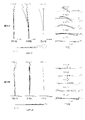
- 1A, 1B, and 1C are cross-sectional views of the variable power optical system according to Example 1 in the wide-angle end state, the intermediate focal length state, and the telephoto end state, respectively.
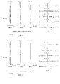
- 2A and 2B are aberration diagrams of the variable power optical system according to Example 1 upon focusing on an object at infinity in the wide-angle end state and the telephoto end state, respectively.
- FIGS. 3A and 3B are aberration diagrams of the variable power optical system according to Example 1 upon focusing on a short-distance object in the wide-angle end state and the telephoto end state, respectively.
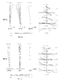
- FIG. 4A, 4B, and 4C are cross-sectional views of the variable power optical system according to the second example in a wide-angle end state, an intermediate focal length state, and a telephoto end state, respectively.
- 5A and 5B are graphs showing various aberrations of the variable power optical system according to Example 2 upon focusing on an object at infinity in the wide-angle end state and the telephoto end state, respectively.
- FIG. 6A and FIG. 6B are aberration diagrams of the variable power optical system according to Example 2 upon focusing on a short-distance object in the wide-angle end state and the telephoto end state, respectively.
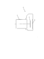
- FIG. 7 is a diagram showing a configuration of a camera including a variable power optical system.
- FIG. 8 is a flowchart showing the outline of the method for manufacturing the variable power optical system.
- variable power optical system of the present embodiment includes, in order from the object side, a first lens group having a negative refractive power, a second lens group having a positive refractive power, and a third lens group. At this time, the distance between the adjacent lens groups changes, and at the time of focusing, the first lens group and the second lens group move along the optical axis, and the following conditional expression (1) is satisfied.
- f1 focal length of the first lens group
- f2 focal length of the second lens group
- the variable power optical system of the present embodiment includes, in order from the object side, a first lens group having a negative refractive power, a second lens group having a positive refractive power, and a third lens group. At this time, the distance between the adjacent lens groups changes. With this configuration, the variable power optical system of the present embodiment realizes variable power, and various aberrations can be corrected well.
- variable power optical system of the present embodiment the first lens group and the second lens group move along the optical axis when focusing. With this configuration, the variable power optical system of the present embodiment can secure a sufficient variable power ratio.
- Conditional expression (1) is a conditional expression for defining an appropriate range for the ratio of the focal length of the first lens group and the focal length of the second lens group.
- the relationship between the focal length of the first lens group and the focal length of the second lens group becomes unsuitable, so spherical aberration and coma are reduced. It becomes difficult to suppress the occurrence of aberration.
- the upper limit values of the conditional expression (1) are set to 2.80, 2.70, 2.60, 2.50, 2.40, 2.30, 2. It is preferably 20, 2.10, 2.08, and more preferably 2.05.
- the lower limit value of the conditional expression (1) is set to 1.20, 1.30, 1.40, 1.50, 1.60, 1.70, and further 1. It is preferably 0.71.
- variable power optical system of the present embodiment can favorably correct various aberrations such as spherical aberration and coma.
- variable power optical system of the present embodiment includes, in order from the object side, a first lens group having a negative refractive power, a second lens group having a positive refractive power, and a third lens group. At this time, the distance between adjacent lens groups changes, and the first lens group and the second lens group each have one or more convex air lenses.
- the variable power optical system of the present embodiment includes, in order from the object side, a first lens group having a negative refractive power, a second lens group having a positive refractive power, and a third lens group. At this time, the distance between the adjacent lens groups changes. With this configuration, the variable power optical system of the present embodiment realizes variable power, and various aberrations can be corrected well.
- each of the first lens group and the second lens group has one or more convex air lenses.
- the air lens refers to a lens formed by an air portion between adjacent lenses.
- variable power optical system of the present embodiment satisfies the following conditional expression (2).
- f1 focal length of the first lens group
- fw focal length of the variable power optical system in the wide-angle end state
- Conditional expression (2) is a conditional expression for defining an appropriate range for the ratio of the focal length of the first lens group and the focal length of the variable power optical system in the wide-angle end state.
- the variable power optical system of the present embodiment can satisfactorily correct various aberrations such as spherical aberration and coma by satisfying conditional expression (2).
- the range of the conditional expression (2) of the variable power optical system of the present embodiment is deviated, the relationship between the focal length of the variable power optical system and the focal length of the first lens group in the wide-angle end state becomes unsuitable. It becomes difficult to satisfactorily correct various aberrations such as aberration and coma.
- the upper limit of conditional expression (2) is set to 3.30, 3.20, 3.15, 3.10, 3.05, and 3.00. It is preferable.
- the lower limit of conditional expression (2) is set to 2.70, 2.75, 2.80, 2.85, 2.90, and further 2.92. It is preferable.
- variable power optical system of the present embodiment satisfies the following conditional expression (3).
- FN® F number of the variable power optical system
- Conditional expression (3) is a conditional expression for defining an appropriate range of the F number of the variable power optical system.
- the variable power optical system of the present embodiment can realize an optical system capable of excellent photographing even in a dark place over the entire zoom range.
- the corresponding value of the conditional expression (3) of the variable power optical system of the present embodiment exceeds the upper limit value, the brightness is insufficient and it becomes impossible to provide high image quality in a dark place.
- the upper limit value of the conditional expression (3) is set to 1.38, 1.35, 1.33, 1.30, 1.28, 1.25, and further 1. .24 is preferable.
- the second lens group has a first positive lens closest to the object side and satisfies the following conditional expression (4). (4) 1.50 ⁇ f21/f2 ⁇ 4.50
- f21 focal length of the first positive lens
- f2 focal length of the second lens group
- variable power optical system of the present embodiment since the second lens group has the first positive lens closest to the object side, radial enlargement can be prevented and coma can be corrected well.
- the conditional expression (4) is a conditional expression for defining an appropriate range for the ratio of the focal length of the first positive lens and the focal length of the second lens group.
- the range of the conditional expression (4) of the variable power optical system of the present embodiment is exceeded, the relationship between the focal length of the first positive lens and the focal length of the second lens group becomes unsuitable, so spherical aberration and coma are reduced. Aberrations occur, making correction difficult and enlarging the optical system.
- the upper limit of conditional expression (4) is set to 4.30, 4.20, 4.10, 4.00, 3.90, and further 3.80. It is preferable.
- the lower limit values of conditional expression (4) are set to 1.70, 1.80, 1.90, 2.00, 2.10, and 2.20. It is preferable.
- the second lens group has a first positive lens and a second positive lens in order from the most object side, and the following conditional expression (5) is satisfied. Is desirable. (5) 1.00 ⁇ f22/f2 ⁇ 3.50 However, f22: focal length of the second positive lens f2: focal length of the second lens group
- the second lens group has the first positive lens and the second positive lens in order from the most object side, so that it is possible to excellently correct aberrations even with a large aperture.
- Conditional expression (5) is a conditional expression for defining an appropriate range for the ratio of the focal length of the second positive lens and the focal length of the second lens group.
- the variable power optical system of the present embodiment can favorably correct spherical aberration and coma by satisfying conditional expression (5).
- the range of the conditional expression (5) of the variable power optical system of the present embodiment is exceeded, the relationship between the focal length of the second positive lens and the focal length of the second lens group becomes unsuitable, so spherical aberration and coma are reduced. It becomes difficult to correct the aberration, or the optical system becomes huge.
- the upper limit values of the conditional expression (5) are set to 3.30, 3.20, 3.10, 3.00, 2.90, 2.80, 2. 70, 2.60, 2.50, 2.40, 2.30, and more preferably 2.25.
- the lower limit of conditional expression (5) is set to 1.20, 1.25, 1.30, 1.35, 1.40, and further 1.45. It is preferable.
- the second lens group has a first positive lens and a second positive lens in order from the most object side, and the following conditional expression (6) is satisfied. Is desirable. (6) 0.50 ⁇ f2F/f2 ⁇ 2.00 However, f2F: Composite focal length of the first positive lens and the second positive lens f2: Focal length of the second lens group
- the second lens group has the first positive lens and the second positive lens in order from the object side, so that good aberration correction is possible even with a large aperture.
- Conditional expression (6) is a conditional expression for defining an appropriate range for the ratio of the combined focal length of the first positive lens and the second positive lens and the focal length of the second lens group.
- the variable power optical system according to the present embodiment is small in size and can satisfactorily correct aberrations by satisfying conditional expression (6).
- the range of conditional expression (6) of the variable power optical system of the present embodiment is exceeded, the relationship between the combined focal length of the first positive lens and the second positive lens and the focal length of the second lens group is not appropriate. Since it disappears, the optical system becomes huge, and it becomes difficult to correct spherical aberration and coma.
- the upper limit values of the conditional expression (6) are set to 1.80, 1.70, 1.60, 1.50, 1.40, 1.30, 1. It is preferably 20 and more preferably 1.15.
- the lower limit of conditional expression (6) is set to 0.70, 0.80, 0.90, 0.95, 1.00, and 1.05. It is preferable.
- the second lens group includes an a-th positive lens, an a-th negative lens, a b-th negative lens, and a b-th positive lens which are sequentially arranged from the object side.
- An air lens formed by the surfaces of the a-th negative lens and the b-th negative lens facing each other has a biconvex shape, and at least one is provided on the object side of the partial lens group. It is desirable to have a positive lens and satisfy the following conditional expression (7). (7) 0.50 ⁇ f2A/f2 ⁇ 2.00 However, f2A: composite focal length of all the positive lenses arranged on the object side of the partial lens group f2: focal length of the second lens group
- the second lens group is a partial lens including an a-th positive lens, an a-th negative lens, a b-th negative lens, and a b-th positive lens that are sequentially arranged from the object side.
- the air lens formed of the surfaces of the a-th negative lens and the b-th negative lens facing each other having a group has a biconvex shape, so that spherical aberration and coma aberration can be achieved while having an effect of correcting field curvature. Can be satisfactorily corrected.
- the variable power optical system of the present embodiment has at least one positive lens on the object side of the partial lens group, so that spherical aberration can be corrected more effectively.
- conditional expression (7) is a conditional expression for defining an appropriate range for the ratio of the combined focal length of all the positive lenses arranged on the object side of the partial lens group and the focal length of the second lens group. is there.
- the variable power optical system of the present embodiment is small in size and can satisfactorily correct aberrations by satisfying conditional expression (7).
- conditional expression (7) of the variable power optical system of the present embodiment If the range of conditional expression (7) of the variable power optical system of the present embodiment is exceeded, the combined focal lengths of all the positive lenses arranged on the object side of the partial lens group and the focal length of the second lens group Therefore, the optical system becomes huge and it becomes difficult to correct spherical aberration and coma.
- the upper limit values of conditional expression (7) are set to 1.80, 1.70, 1.60, 1.50, 1.40, 1.30, 1. It is preferably 20 and more preferably 1.15.
- the lower limit of conditional expression (7) is set to 0.70, 0.80, 0.90, 0.95, 1.00, and 1.05. It is preferable.
- the first lens group has a positive lens closest to the image surface side and satisfies the following conditional expression (8).
- (8) 1.00 ⁇ f1R/(-f1) ⁇ 6.00
- f1R focal length of the positive lens arranged closest to the image plane of the first lens group
- f1 focal length of the first lens group
- the first lens group has the positive lens closest to the image surface side, whereby spherical aberration can be satisfactorily corrected.
- Conditional expression (8) is a conditional expression for defining an appropriate range for the ratio of the focal length of the positive lens arranged closest to the image plane of the first lens unit and the focal length of the first lens unit. ..
- the variable power optical system of the present embodiment can favorably correct spherical aberration by satisfying conditional expression (8).
- the range of the conditional expression (8) of the variable power optical system of the present embodiment is exceeded, the focal length of the positive lens arranged closest to the image plane of the first lens group and the focal length of the first lens group Therefore, it becomes difficult to correct spherical aberration.
- the upper limit of conditional expression (8) is set to 5.80, the effect of this embodiment can be made more reliable.
- the upper limits of conditional expression (8) are set to 5.60, 5.50, 5.30, 5.20, 5.10, 5.00, and 4 It is preferably set to 0.90.
- the lower limit of conditional expression (8) is set to 1.20, 1.30, 1.40, 1.50, 1.60, and further 1.70. It is preferable.
- variable power optical system of the present embodiment satisfies the following conditional expression (9). (9) 1.80 ⁇ r3R/Bf3w ⁇ 4.30
- r3R radius of curvature of the image surface side lens surface of the lens arranged closest to the image surface of the third lens group
- Bf3w image surface of the lens arranged closest to the image surface of the third lens group in the wide-angle end state Air conversion distance on the optical axis from the side lens surface to the image surface
- conditional expression (9) is defined by the radius of curvature of the image surface side lens surface of the lens arranged closest to the image surface of the third lens group and the lens arranged closest to the image surface of the third lens group in the wide-angle end state. Is a conditional expression for defining an appropriate range for the ratio of the air-equivalent distance on the optical axis from the image surface side lens surface to the image surface.
- the variable power optical system of the present embodiment can satisfactorily correct field curvature and spherical aberration by satisfying conditional expression (9).
- the range of the conditional expression (9) of the variable power optical system of the present embodiment is deviated, the radius of curvature of the lens of the third lens group arranged closest to the image plane and the third lens group in the wide-angle end state. Since the relationship with the air-equivalent distance on the optical axis from the image surface side lens surface of the lens arranged closest to the image surface side to the image surface is not appropriate, it becomes difficult to correct the field curvature and spherical aberration.
- the upper limits of conditional expression (9) are set to 4.10, 4.00, 3.90, 3.80, 3.70, 3.60, 3. 50, 3.40, 3.30, and more preferably 3.26.
- the lower limit of conditional expression (9) is set to 2.10, 2.20, 2.30, 2.40, 2.50, and further 2.60. It is preferable.
- variable power optical system of the present embodiment satisfies the following conditional expression (10).
- r2R radius of curvature
- Bf2w image surface of the lens arranged closest to the image surface side of the second lens group in the wide-angle end state Air conversion distance on the optical axis from the side lens surface to the image surface
- conditional expression (10) is defined by the radius of curvature of the image surface side lens surface of the lens arranged closest to the image surface of the second lens group and the lens arranged closest to the image surface of the second lens group in the wide-angle end state. Is a conditional expression for defining an appropriate range for the ratio of the air-equivalent distance on the optical axis from the image surface side lens surface to the image surface.
- the variable power optical system of the present embodiment can satisfactorily correct spherical aberration and field curvature by satisfying conditional expression (10).
- the range of the conditional expression (10) of the variable power optical system of the present embodiment is exceeded, the radius of curvature of the image surface side lens surface of the lens arranged closest to the image surface of the second lens group and the wide-angle end state. Since the relationship with the air-equivalent distance on the optical axis from the image-side lens surface to the image surface of the lens disposed closest to the image surface in the second lens group in is not appropriate, spherical aberration and field curvature are corrected. Becomes difficult.
- the upper limit values of the conditional expression (10) are set to 1.90, 1.80, 1.70, 1.60, 1.50, 1.40, 1. 35, and preferably 1.32.
- the lower limit of conditional expression (10) is set to 0.70, 0.80, 0.90, 1.00, 1.10, 1.15, and 1 .20 is preferable.
- variable power optical system of the present embodiment satisfies the following conditional expression (11). (11) 0.15 ⁇ Bfw/fw ⁇ 1.00
- Bfw Back focus of the variable power optical system in the wide-angle end state
- fw Focal length of the variable power optical system in the wide-angle end state
- Conditional expression (11) is a conditional expression for defining an appropriate range for the ratio of the back focus of the variable power optical system in the wide-angle end state and the focal length of the variable power optical system in the wide-angle end state.
- the range of the conditional expression (11) of the variable power optical system of the present embodiment is deviated from, the relationship between the focal length and the back focus of the variable power optical system in the wide-angle end state becomes unsuitable, and therefore coma aberration in the wide-angle end state. It becomes difficult to correct various aberrations such as.
- the upper limit of conditional expression (11) is set to 0.80, 0.70, 0.65, 0.60, 0.55, and 0.53. It is preferable.
- the lower limit values of conditional expression (11) are set to 0.20, 0.22, 0.24, 0.25, 0.28, 0.30, 0. 32, 0.34, and more preferably 0.35.
- variable power optical system of the present embodiment satisfies the following conditional expression (12). (12) 35.00° ⁇ 2 ⁇ w ⁇ 80.00° However, 2 ⁇ w: total angle of view of the variable power optical system in the wide-angle end state
- Conditional expression (12) is a conditional expression for defining an appropriate range of the total angle of view of the variable power optical system in the wide-angle end state.
- conditional expression (12) By setting the upper limit of conditional expression (12) to 78.00°, the effect of this embodiment can be made more reliable. Further, in order to secure the effect of the present embodiment, it is preferable to set the upper limit values of the conditional expression (12) to 76.00°, 75.00°, 74.00°, and 73.00°.
- the lower limit of conditional expression (12) is set to 40.00°, 42.00°, 45.00°, 46.00°, and further 47.00°. Preferably.
- variable power optical system of the present embodiment satisfies the following conditional expression (13). (13) 10.00° ⁇ 2 ⁇ t ⁇ 60.00° However, 2 ⁇ t: total angle of view of the variable power optical system in the telephoto end state
- Conditional expression (13) is a conditional expression for defining an appropriate range of the total angle of view of the variable power optical system in the telephoto end state.
- the variable power optical system of the present embodiment has a wide angle of view and can suppress aberration fluctuation in the telephoto end state.
- the upper limit value of the conditional expression (13) is set to 53.00°, 50,00°, 49.00°, 48.00°, and further 47.00°. Preferably.
- the lower limit of conditional expression (13) is set to 12.00°, 13.00°, 14.00°, 15.00°, and further 16.00°. Preferably.
- the first lens group has at least one positive lens that satisfies the following conditional expression (14).
- (14) 0.673 ⁇ gFLp+0.0022* ⁇ dLp ⁇ 0.750
- ⁇ dLp Abbe number ⁇ gFLp for the d line of the positive lens
- the Abbe number ⁇ dLp and the partial dispersion ratio ⁇ gFLp are nC for the refractive index for the C line (wavelength 656.3 nm), nd for the refractive index for the d line (wavelength 587.6 nm), and for the F line (wavelength 486.1 nm).
- the refractive index is nF
- the refractive index for the g-line is ng
- ⁇ dLp (nd-1)/(nF-nC)
- ⁇ gFLp (ng-nF)/(nF-nC)
- the conditional expression (14) is a conditional expression that defines the glass material used for the positive lens included in the first lens group. By having a positive lens that satisfies the conditional expression (14), it is possible to excellently correct axial chromatic aberration.
- conditional expression (14) of the optical system of the present embodiment If the range of the conditional expression (14) of the optical system of the present embodiment is exceeded, it becomes difficult to favorably correct the axial chromatic aberration.
- the upper limit of conditional expression (14) By setting the upper limit of conditional expression (14) to 0.730, the effect of this embodiment can be made more reliable. Further, in order to further secure the effect of the present embodiment, it is preferable to set the upper limit value of the conditional expression (14) to 0.720, 0.710, 0.700, and further 0.695.
- the effect of this embodiment can be made more reliable. Further, in order to further secure the effect of the present embodiment, it is preferable to set the lower limit values of the conditional expression (14) to 0.680, 0.685, 0.688, 0.690, and 0.692.
- variable power optical system of the present embodiment satisfies the following conditional expression (15).
- Pex Distance from paraxial exit pupil position to image point
- fw Focal length of the variable power optical system in the wide-angle end state
- Conditional expression (15) is a conditional expression for defining an appropriate range for the ratio of the distance from the paraxial exit pupil position to the image point and the focal length of the variable power optical system in the wide-angle end state.
- the variable power optical system of the present embodiment can be made compact and have good performance by satisfying conditional expression (15).
- the range of the conditional expression (15) of the variable power optical system of the present embodiment is deviated, the relationship between the distance from the paraxial exit pupil position to the image point and the focal length of the variable power optical system in the wide-angle end state becomes. Since it is not appropriate, the optical system becomes huge and it becomes difficult to correct distortion.
- the upper limit of conditional expression (15) is set to 1.80, 1,75, 1.70, 1.65, 1.64, and 1.62. It is preferable.
- the lower limit of conditional expression (15) is set to 0.70, 0.80, 0.90, 1.00, 1.05, and further 1.10. It is preferable.
- the first lens group and the second lens group each have one convex air lens and satisfy the following conditional expression. (16)-1.00 ⁇ (r2L1+r1L1)/(r2L1-r1L1) ⁇ 3.00
- r1L1 radius of curvature of object-side lens surface of air lens of the first lens group
- r2L1 radius of curvature of image-side lens surface of air lens of the first lens group
- conditional expression (16) is a conditional expression for defining the shape factor of the convex air lens included in the first lens group.
- the range of the conditional expression (16) of the optical system of the present embodiment is deviated, the shape of the air lens becomes a shape disadvantageous to the peripheral light flux, so that spherical aberration, distortion, and field curvature can be reduced. Correction becomes difficult.
- the upper limit of conditional expression (16) is set to 2.50, 2.30, 2.00, 1.80, 1.50, 1.30, and 1 It is preferably set to 0.00.
- the lower limit of conditional expression (16) is set to ⁇ 0.05, ⁇ 0.03, ⁇ 0.01, 0.01, and 0.02. Is preferred.
- the first lens group and the second lens group each have one convex air lens and satisfy the following conditional expression. (17)-2.00 ⁇ (r2L2-r1L2)/(r2L2+r1L2) ⁇ 2.00
- r1L2 radius of curvature of object-side lens surface of air lens of the second lens group
- r2L2 radius of curvature of image-side lens surface of air lens of the second lens group
- conditional expression (17) is a conditional expression for defining the shape factor of the air lens included in the second lens group.
- the shape of the air lens becomes a shape disadvantageous to the peripheral light flux, so that spherical aberration, distortion, and curvature of field occur. Correction becomes difficult.
- the upper limit of conditional expression (17) is set to 1.90, the effect of this embodiment can be made more reliable.
- the conditional values of the conditional expression (17) are set to 1.80, 1.60, 1.50, 1.30, 1.20, 1.10, Furthermore, it is preferable to set it to 1.00.
- the lower limit values of conditional expression (17) are set to -1.80, -1.60, -1.50, -1.30, -1.20, -. It is preferably set to 1.10, more preferably -1.00.
- each of the first lens group and the second lens group has one convex air lens, and the air lens of the first lens group and the second lens group. It is desirable to have at least four positive lenses or more between them and the air lens. This makes it possible to excellently correct various aberrations such as spherical aberration.
- the optical device of this embodiment has a variable power optical system having the above-described configuration. As a result, it is possible to satisfactorily correct various aberrations and realize a high-performance and compact optical device.
- the method for manufacturing a variable power optical system has a variable power system including, in order from the object side, a first lens group having a negative refractive power, a second lens group having a positive refractive power, and a third lens group.
- a method of manufacturing a doubling optical system wherein the distance between adjacent lens groups changes during zooming, and when focusing, the first lens group and the second lens group are arranged along the optical axis.
- Is a method for manufacturing a variable power optical system which is configured so as to satisfy the following conditional expression (1).
- (1) 1.00 ⁇ (-f1)/f2 ⁇ 3.00
- f1 focal length of the first lens group
- f2 focal length of the second lens group
- FIG. 1A, 1B, and 1C are cross-sectional views of the variable power optical system according to Example 1 in the wide-angle end state, the intermediate focal length state, and the telephoto end state, respectively.
- the arrow below each lens group in FIG. 1A indicates the moving direction of each lens group during zooming from the wide-angle end state to the intermediate focal length state.
- the arrow below each lens group in FIG. 1B indicates the moving direction of each lens group during zooming from the intermediate focal length state to the telephoto end state.
- variable power optical system is, in order from the object side, a first lens group G1 having a negative refractive power, a second lens group G2 having a positive refractive power, and a third lens group having a positive refractive power.
- the first lens group G1 includes, in order from the object side, a cemented negative lens in which a positive meniscus lens L11 having a convex surface facing the object side and a negative meniscus lens L12 having a convex surface facing the object side are cemented, and a biconcave negative lens. It comprises a cemented negative lens constructed by cementing L13 and a positive meniscus lens L14 having a concave surface facing the object side, and a positive meniscus lens L15 having a convex surface facing the object side.
- the image-side lens surface of the negative meniscus lens L12 and the object-side lens surface of the negative lens L13 form a biconvex air lens La1.
- the second lens group G2 includes, in order from the object side, a biconvex positive lens L21, a positive meniscus lens L22 having a convex surface directed to the object side, a positive meniscus lens L23 having a convex surface directed to the object side, and an object side.
- the image-side lens surface of the negative meniscus lens L24 and the object-side lens surface of the negative lens L25 form a biconvex air lens La2.
- the third lens group G3 includes, in order from the object side, a cemented positive lens in which a biconvex positive lens L31 and a biconcave negative lens L32 are cemented, a biconvex positive lens L33, and a biconcave negative lens. And a cemented positive lens cemented with L34.
- a filter group FL including a low-pass filter and the like is arranged between the third lens group G3 and the image plane I.
- an image pickup device (not shown) composed of CCD, CMOS or the like is arranged on the image plane I.
- the distance between the first lens group G1 and the second lens group G2 and the second lens when zooming from the wide-angle end state to the telephoto end state The first lens group G1, the second lens group G2, and the third lens group G3 move along the optical axis so that the distance between the group G1 and the third lens group G2 changes. Specifically, the first lens group G1 moves to the image side, the second lens group G2 moves to the object side, and the third lens group G3 moves to the object side.
- variable power optical system performs focusing from an object at infinity to a near object by moving the first lens group G1 and the second lens group G2 to the object side along the optical axis. ..
- Table 1 below lists values of specifications of the variable power optical system according to this example.
- f is the focal length
- BF air conversion length
- the air conversion back focus that is, the distance on the optical axis from the lens surface closest to the image side to the image plane I
- the thickness of the filter group FL is the air. Indicates the converted distance.
- m is the order of the optical surfaces counted from the object side
- r is the radius of curvature
- d is the surface distance (the distance between the nth surface (n is an integer) and the (n+1)th surface)
- nd is the d line
- the wavelength is 587.6 nm
- vd is the Abbe number for the d-line (wavelength 587.6 nm)
- ⁇ gF is the partial dispersion ratio between the g-line and the F-line. Note that ⁇ gF is shown only for lenses that satisfy the conditional expression (14).
- OP represents an object plane
- Dn (n is an integer) represents a variable surface distance
- ST represents an aperture stop
- I represents an image plane.
- "*" is added to the surface number, and the paraxial radius of curvature is shown in the column of the radius of curvature r.
- [Aspherical surface data] indicates an aspherical surface coefficient and a conic constant when the shape of the aspherical surface shown in [Surface data] is expressed by the following equation.
- x (h 2 /r)/[1+ ⁇ 1- ⁇ (h/r) 2 ⁇ 1/2 ] +bh 4 +ch 6 +dh 8 +eh 10 +fh 12 +gh 14
- h is the height in the direction perpendicular to the optical axis
- x is the sag amount that is the distance along the optical axis direction from the tangent plane of the vertex of the aspherical surface at the height h to the aspherical surface
- ⁇ is the conic constant.
- f is the focal length of the entire optical system
- FNo is the F number
- 2 ⁇ is the total angle of view (unit is “°”)
- Y is the maximum image height
- TL is the optical system according to the present embodiment.
- the total length that is, the distance from the first surface to the image plane I on the optical axis
- BF air conversion length
- W indicates the wide-angle end state
- T indicates the telephoto end state.
- f is the focal length of the entire optical system
- ⁇ is the close-up shooting magnification
- Dn (n is an integer) is the nth surface and the n+1th surface.
- W indicates the wide-angle end state
- T indicates the telephoto end state.
- the [lens group data] shows the starting surface number ST and the focal length f of each lens group.
- [Corresponding value of conditional expression] shows the corresponding value of each conditional expression.
- mm is generally used as the unit of the focal length f, the radius of curvature r, and other lengths listed in Table 1.
- the optical system is not limited to this because the same optical performance can be obtained even if the optical system is enlarged or reduced proportionally. Note that the reference numerals in Table 1 described above are similarly used in the tables of the respective embodiments described later.
- FIGS. 3A and 3B are aberration diagrams of the variable power optical system according to Example 1 upon focusing on a short-distance object in the wide-angle end state and the telephoto end state, respectively.
- FNO indicates the F number
- Y indicates the image height
- NA indicates the numerical aperture.
- C is C line (wavelength 656.3 nm)
- d is d line (wavelength 587.6 nm)
- F is F line (wavelength 486.1 nm)
- g is g line (wavelength 435.8 nm).
- the solid line shows the sagittal image plane
- the broken line shows the meridional image plane
- the solid line represents the meridional coma aberration
- the broken line represents the sagittal coma aberration with respect to the d line.
- the coma aberration diagram shows coma aberration at each image height Y. Note that the same reference numerals as in this example are used in the aberration diagrams of the examples described below.
- the optical system according to the present example is excellent in correcting various aberrations from the state of focusing the object at infinity to the focusing of the object at a short distance, and further correcting the aberrations from the wide-angle end state to the telephoto end state. It can be seen that it has excellent imaging performance.
- FIG. 4A, 4B, and 4C are cross-sectional views of the variable power optical system according to Example 2 in the wide-angle end state, the intermediate focal length state, and the telephoto end state, respectively.
- the arrow below each lens group in FIG. 4A indicates the moving direction of each lens group during zooming from the wide-angle end state to the intermediate focal length state.
- the arrow below each lens group in FIG. 4B indicates the moving direction of each lens group during zooming from the intermediate focal length state to the telephoto end state.
- variable power optical system is, in order from the object side, a first lens group G1 having a negative refractive power, a second lens group G2 having a positive refractive power, and a third lens group having a positive refractive power.
- the first lens group G1 includes, in order from the object side, a cemented negative lens in which a positive meniscus lens L11 having a convex surface facing the object side and a negative meniscus lens L12 having a convex surface facing the object side are cemented, and a biconcave negative lens. It comprises a cemented negative lens constructed by cementing L13 and a positive meniscus lens L14 having a convex surface facing the object side, and a positive meniscus lens L15 having a convex surface facing the object side.
- the image-side lens surface of the negative meniscus lens L12 and the object-side lens surface of the negative lens L13 form a biconvex air lens La1.
- the second lens group G2 includes, in order from the object side, a biconvex positive lens L21, a positive meniscus lens L22 having a convex surface directed to the object side, a positive meniscus lens L23 having a convex surface directed to the object side, and an object side.
- a cemented negative lens in which a biconvex positive lens L28 and a biconcave negative lens L29 are cemented.
- the image-side lens surface of the negative meniscus lens L24 and the object-side lens surface of the negative lens L25 form a biconvex air lens La2.
- the third lens group G3 includes, in order from the object side, a cemented positive lens in which a biconvex positive lens L31 and a biconcave negative lens L32 are cemented, a biconvex positive lens L33, and a biconcave negative lens. And a cemented positive lens cemented with L34.
- a filter group FL including a low-pass filter and the like is arranged between the third lens group G3 and the image plane I.
- an image pickup device (not shown) composed of CCD, CMOS or the like is arranged on the image plane I.
- the distance between the first lens group G1 and the second lens group G2 and the second lens when zooming from the wide-angle end state to the telephoto end state The first lens group G1, the second lens group G2, and the third lens group G3 move along the optical axis so that the distance between the group G1 and the third lens group G2 changes. Specifically, the first lens group G1 moves to the image side, the second lens group G2 moves to the object side, and the third lens group G3 moves to the object side.
- variable power optical system performs focusing from an object at infinity to a near object by moving the first lens group G1 and the second lens group G2 to the object side along the optical axis. ..
- Table 2 below shows values of specifications of the variable power optical system according to the present embodiment.
- FIG. 5A and FIG. 5B are aberration diagrams of the variable power optical system according to Example 2 upon focusing on an object at infinity in the wide-angle end state and the telephoto end state, respectively.
- FIG. 6A and FIG. 6B are aberration diagrams of the variable power optical system according to Example 2 upon focusing on a short-distance object in the wide-angle end state and the telephoto end state, respectively.
- the optical system according to the present example is excellent in correcting various aberrations from the state of focusing the object at infinity to the focusing of the object at a short distance, and further correcting the aberrations from the wide-angle end state to the telephoto end state. It can be seen that it has excellent imaging performance.
- variable power optical system of the present embodiment has a three-group configuration
- the present embodiment is not limited to this, and a variable power optical system of another group configuration (for example, four groups) is configured. You can also do it.
- a configuration may be adopted in which a lens or a lens group is added to the most object side or the most image side of the variable power optical system of each of the above embodiments.
- a lens or a lens group may be added between adjacent lens groups.
- the lens group may be composed of at least one lens.
- the first lens group and the second lens group are focusing lens groups.
- a focusing lens group can be applied to autofocus, and is also suitable for driving by a motor for autofocus, for example, an ultrasonic motor, a stepping motor, a VCM motor or the like.
- variable power optical system of each of the above-described examples either the whole lens group or a part thereof is moved so as to include a component in a direction perpendicular to the optical axis as an image stabilization group, or the optical axis is changed. It is also possible to adopt a configuration for performing vibration isolation by rotationally moving (swinging) in the in-plane direction.
- the aperture stop of the variable power optical system of each of the above embodiments may be configured such that a lens frame substitutes its role without providing a member as the aperture stop.
- the lens surface of the lens constituting the variable power optical system of each of the above-described embodiments may be a spherical surface or a flat surface, or may be an aspherical surface.
- the lens surface is a spherical surface or a flat surface, lens processing and assembly adjustment are facilitated, and deterioration of optical performance due to an error in lens processing and assembly adjustment can be prevented, which is preferable. Further, even if the image plane is deviated, the drawing performance is less deteriorated, which is preferable.
- the lens surface is an aspherical surface, either an aspherical surface formed by grinding, a glass mold aspherical surface formed by molding glass into an aspherical shape, or a composite aspherical surface in which a resin provided on the glass surface is formed into an aspherical shape.
- the lens surface may be a diffractive surface, and the lens may be a gradient index lens (GRIN lens) or a plastic lens.
- an antireflection film having a high transmittance in a wide wavelength range may be provided on the lens surface of the lens that constitutes the variable power optical system of each of the above-described embodiments. Thereby, flare and ghost can be reduced, and high optical performance with high contrast can be achieved.
- FIG. 7 is a view showing the arrangement of a camera provided with the variable power optical system of this embodiment.
- the camera 1 is a lens-interchangeable mirrorless camera that includes, as the taking lens 2, the variable power optical system according to the first embodiment.
- the camera 1 In the camera 1, light from an object (subject) (not shown) is condensed by the taking lens 2 and passes through an OLED (Optical low pass filter) (not shown) on the image pickup surface of the image pickup unit 3. A subject image is formed on. Then, the subject image is photoelectrically converted by the photoelectric conversion element provided in the imaging unit 3 to generate an image of the subject. This image is displayed on an EVF (Electronic view finder) 4 provided in the camera 1. This allows the photographer to observe the subject via the EVF 4. When the photographer presses a release button (not shown), the image of the subject generated by the imaging unit 3 is stored in a memory (not shown). In this way, the photographer can photograph an object with the camera 1.
- OLED Optical low pass filter
- the variable power optical system according to the first embodiment mounted on the camera 1 as the taking lens 2 is small, and from the time of focusing an object at infinity to the time of focusing a short-distance object, Further, it has excellent imaging performance by satisfactorily correcting various aberrations from the wide-angle end state to the telephoto end state. That is, the camera 1 has high optical performance capable of excellently correcting various aberrations, and can be downsized. Even if a camera in which the variable power optical system according to the second example is mounted as the taking lens 2 is configured, the same effect as that of the camera 1 can be obtained. Further, even when the variable power optical system according to each of the above embodiments is mounted on a single-lens reflex type camera having a quick return mirror and observing an object with a finder optical system, the same effect as the camera 1 can be obtained. it can.
- FIG. 8 is a flow chart showing the outline of the method for manufacturing the optical system of the present embodiment.
- the method for manufacturing the optical system of the present embodiment shown in FIG. 8 includes, in order from the object side, a first lens group having a negative refractive power, a second lens group having a positive refractive power, and a third lens group.
- Step S1 It is configured such that the distance between adjacent lens groups changes during zooming.
- Step S2 At the time of focusing, the first lens group and the second lens group are configured to move along the optical axis.
- Step S3 Configure so as to satisfy the following conditional expression (1). (1) 1.00 ⁇ (-f1)/f2 ⁇ 3.00 However, f1: focal length of the first lens group f2: focal length of the second lens group
- variable power optical system of the present embodiment it is possible to manufacture a variable power optical system having a small size and high optical performance capable of excellently correcting various aberrations.
Landscapes
- Physics & Mathematics (AREA)
- General Physics & Mathematics (AREA)
- Optics & Photonics (AREA)
- Lenses (AREA)
Abstract
Description
物体側から順に、負の屈折力を有する第1レンズ群と、正の屈折力を有する第2レンズ群と、第3レンズ群とを有し、
変倍に際し、隣り合う各レンズ群の間隔が変化し、
合焦に際し、前記第1レンズ群と前記第2レンズ群とが光軸に沿って移動し、
以下の条件式を満足する変倍光学系である。
(1)1.00<(-f1)/f2<3.00
ただし、
f1:前記第1レンズ群の焦点距離
f2:前記第2レンズ群の焦点距離
物体側から順に、負の屈折力を有する第1レンズ群と、正の屈折力を有する第2レンズ群と、第3レンズ群とを有する変倍光学系の製造方法であって、
変倍に際し、隣り合う各レンズ群の間隔が変化するように構成し、
合焦に際し、前記第1レンズ群と前記第2レンズ群とが光軸に沿って移動するように構成し、
以下の条件式を満足する変倍光学系の製造方法である。
(1)1.00<(-f1)/f2<3.00
ただし、
f1:前記第1レンズ群の焦点距離
f2:前記第2レンズ群の焦点距離
本実施形態の変倍光学系は、物体側から順に、負の屈折力を有する第1レンズ群と、正の屈折力を有する第2レンズ群と、第3レンズ群とを有し、変倍に際し、隣り合う各レンズ群の間隔が変化し、合焦に際し、前記第1レンズ群と前記第2レンズ群とが光軸に沿って移動し、以下の条件式(1)を満足する。
(1)1.00<(-f1)/f2<3.00
ただし、
f1:前記第1レンズ群の焦点距離
f2:前記第2レンズ群の焦点距離
なお、条件式(1)の上限値を2.90に設定することで、本実施形態の効果をより確実なものとすることができる。また、本実施形態の効果をより確実にするために、条件式(1)の上限値を2.80、2.70、2.60、2.50、2.40、2.30、2.20、2.10、2.08、さらに2.05にすることが好ましい。
なお、空気レンズとは、隣り合うレンズとレンズの間の空気部分で形成されるレンズのことをいう。
(2)2.50<(-f1)/fw<3.50
ただし、
f1:前記第1レンズ群の焦点距離
fw:広角端状態における前記変倍光学系の焦点距離
なお、条件式(2)の上限値を3.40に設定することで、本実施形態の効果をより確実なものとすることができる。また、本実施形態の効果をより確実にするために、条件式(2)の上限値を3.30、3.20、3.15、3.10、3.05、さらに3.00にすることが好ましい。
(3)FNо<1.45
ただし、
FNо:前記変倍光学系のFナンバー
なお、条件式(3)の上限値を1.41に設定することで、本実施形態の効果をより確実なものとすることができる。また、本実施形態の効果をより確実にするために、条件式(3)の上限値を1.38、1.35、1.33、1.30、1.28、1.25、さらに1.24にすることが好ましい。
(4)1.50<f21/f2<4.50
ただし、
f21:前記第1正レンズの焦点距離
f2:前記第2レンズ群の焦点距離
なお、条件式(4)の上限値を4.40に設定することで、本実施形態の効果をより確実なものとすることができる。また、本実施形態の効果をより確実にするために、条件式(4)の上限値を4.30、4.20、4.10、4.00、3.90、さらに3.80にすることが好ましい。
(5)1.00<f22/f2<3.50
ただし、
f22:前記第2正レンズの焦点距離
f2:前記第2レンズ群の焦点距離
なお、条件式(5)の上限値を3.40に設定することで、本実施形態の効果をより確実なものとすることができる。また、本実施形態の効果をより確実にするために、条件式(5)の上限値を3.30、3.20、3.10、3.00、2.90、2.80、2.70、2.60、2.50、2.40、2.30、さらに2.25にすることが好ましい。
(6)0.50<f2F/f2<2.00
ただし、
f2F:前記第1正レンズと前記第2正レンズとの合成焦点距離
f2:前記第2レンズ群の焦点距離
なお、条件式(6)の上限値を1.90に設定することで、本実施形態の効果をより確実なものとすることができる。また、本実施形態の効果をより確実にするために、条件式(6)の上限値を1.80、1.70、1.60、1.50、1.40、1.30、1.20、さらに1.15にすることが好ましい。
(7)0.50<f2A/f2<2.00
ただし、
f2A:前記部分レンズ群の物体側に配置された全ての前記正レンズの合成焦点距離
f2:前記第2レンズ群の焦点距離
なお、条件式(7)の上限値を1.90に設定することで、本実施形態の効果をより確実なものとすることができる。また、本実施形態の効果をより確実にするために、条件式(7)の上限値を1.80、1.70、1.60、1.50、1.40、1.30、1.20、さらに1.15にすることが好ましい。
(8)1.00<f1R/(-f1)<6.00
ただし、
f1R:前記第1レンズ群の最も像面側に配置された正レンズの焦点距離
f1:前記第1レンズ群の焦点距離
なお、条件式(8)の上限値を5.80に設定することで、本実施形態の効果をより確実なものとすることができる。また、本実施形態の効果をより確実にするために、条件式(8)の上限値を5.60、5.50、5.30、5.20、5.10、5.00、さらに4.90にすることが好ましい。
(9)1.80<r3R/Bf3w<4.30
ただし、
r3R:前記第3レンズ群の最も像面側に配置されるレンズの像面側レンズ面の曲率半径
Bf3w:広角端状態における前記第3レンズ群の最も像面側に配置されるレンズの像面側レンズ面から像面までの光軸上の空気換算距離
なお、条件式(9)の上限値を4.20に設定することで、本実施形態の効果をより確実なものとすることができる。また、本実施形態の効果をより確実にするために、条件式(9)の上限値を4.10、4.00、3.90、3.80、3.70、3.60、3.50、3.40、3.30、さらに3.26にすることが好ましい。
(10)0.50<r2R/Bf2w<2.20
ただし、
r2R:前記第2レンズ群の最も像面側に配置されるレンズの像面側レンズ面の曲率半径
Bf2w:広角端状態における前記第2レンズ群の最も像面側に配置されるレンズの像面側レンズ面から像面までの光軸上の空気換算距離
なお、条件式(10)の上限値を2.00に設定することで、本実施形態の効果をより確実なものとすることができる。また、本実施形態の効果をより確実にするために、条件式(10)の上限値を1.90、1.80、1.70、1.60、1.50、1.40、1.35、さらに1.32にすることが好ましい。
(11)0.15<Bfw/fw<1.00
ただし、
Bfw:広角端状態における前記変倍光学系のバックフォーカス
fw:広角端状態における前記変倍光学系の焦点距離
なお、条件式(11)の上限値を0.90に設定することで、本実施形態の効果をより確実なものとすることができる。また、本実施形態の効果をより確実にするために、条件式(11)の上限値を0.80、0.70、0.65、0.60、0.55、さらに0.53にすることが好ましい。
(12)35.00°<2ωw<80.00°
ただし、
2ωw:広角端状態における前記変倍光学系の全画角
(13)10.00°<2ωt<60.00°
ただし、
2ωt:望遠端状態における前記変倍光学系の全画角
(14)0.673<θgFLp+0.0022*νdLp<0.750
ただし、
νdLp:前記正レンズのd線に対するアッベ数
θgFLp;前記正レンズのg線とF線とによる部分分散比
νdLp=(nd-1)/(nF-nC)
θgFLp=(ng-nF)/(nF-nC)
なお、条件式(14)の上限値を0.730に設定することで、本実施形態の効果をより確実なものとすることができる。また、本実施形態の効果をより確実にするために、条件式(14)の上限値を0.720、0.710、0.700、さらに0.695にすることが好ましい。
(15)0.50<Pex/fw<2.00
ただし、
Pex:近軸射出瞳位置から像点までの距離
fw:広角端状態における前記変倍光学系の焦点距離
なお、条件式(15)の上限値を1.90に設定することで、本実施形態の効果をより確実なものとすることができる。また、本実施形態の効果をより確実にするために、条件式(15)の上限値を1.80、1,75、1.70、1.65、1.64、さらに1.62にすることが好ましい。
(16)-1.00<(r2L1+r1L1)/(r2L1-r1L1)<3.00
ただし、
r1L1:前記第1レンズ群の空気レンズの物体側レンズ面の曲率半径
r2L1:前記第1レンズ群の空気レンズの像側レンズ面の曲率半径
なお、条件式(16)の上限値を2.80に設定することで、本実施形態の効果をより確実なものとすることができる。また、本実施形態の効果をより確実にするために、条件式(16)の上限値を2.50、2.30、2.00、1.80、1.50、1.30、さらに1.00にすることが好ましい。
(17)-2.00<(r2L2-r1L2)/(r2L2+r1L2)<2.00
ただし、
r1L2:前記第2レンズ群の空気レンズの物体側レンズ面の曲率半径
r2L2:前記第2レンズ群の空気レンズの像側レンズ面の曲率半径
なお、条件式(17)の上限値を1.90に設定することで、本実施形態の効果をより確実なものとすることができる。また、本実施形態の効果をより確実なものとするために、条件式(17)の条件値を1.80、1.60、1.50、1.30、1.20、1.10、さらに1.00にすることが好ましい。
(1)1.00<(-f1)/f2<3.00
ただし、
f1:前記第1レンズ群の焦点距離
f2:前記第2レンズ群の焦点距離
(第1実施例)
図1A、図1Bおよび図1Cはそれぞれ、第1実施例に係る変倍光学系の広角端状態、中間焦点距離状態および望遠端状態における断面図である。
図1A中の各レンズ群の下の矢印は、広角端状態から中間焦点距離状態への変倍の際の各レンズ群の移動方向を示している。図1B中の各レンズ群の下の矢印は、中間焦点距離状態から望遠端状態への変倍の際の各レンズ群の移動方向を示している。
負メニスカスレンズL12の像側のレンズ面と負レンズL13の物体側のレンズ面とによって、両凸形状の空気レンズLa1が形成されている。
負メニスカスレンズL24の像側のレンズ面と負レンズL25の物体側のレンズ面とによって、両凸形状の空気レンズLa2が形成されている。
像面I上には、CCDやCMOS等から構成された撮像素子(図示省略)が配置されている。
表1において、fは焦点距離、BF(空気換算長)は空気換算バックフォーカス、すなわち最も像側のレンズ面から像面Iまでの光軸上の距離であって、フィルタ群FLの厚みを空気換算した距離を示す。
[面データ]において、mは物体側から数えた光学面の順番、rは曲率半径、dは面間隔(第n面(nは整数)と第n+1面との間隔)、ndはd線(波長587.6nm)に対する屈折率、νdはd線(波長587.6nm)に対するアッベ数、θgFはg線とF線とによる部分分散比をそれぞれ示している。なお、θgFは条件式(14)を満足するレンズについてのみ示している。また、OPは物体面、Dn(nは整数)は可変の面間隔、STは開口絞り、Iは像面をそれぞれ示している。なお、曲率半径r=∞は平面を示している。空気の屈折率nd=1.00000の記載は省略している。また、レンズ面が非球面である場合には面番号に「*」を付して曲率半径rの欄には近軸曲率半径を示している。
x=(h2/r)/[1+{1-κ(h/r)2}1/2]
+bh4+ch6+dh8+eh10+fh12+gh14
ここで、hを光軸に垂直な方向の高さ、xを高さhにおける非球面の頂点の接平面から当該非球面までの光軸方向に沿った距離であるサグ量、κを円錐定数、b、c、d、e、f、gを非球面係数、rを基準球面の曲率半径である近軸曲率半径とする。なお、「E-n」(n:整数)は「×10-n」を示し、例えば「1.234E-05」は「1.234×10⁻⁵」を示す。2次の非球面係数は0であり、記載を省略している。
[レンズ群データ]には、各レンズ群の始面番号STと焦点距離fを示す。
[条件式対応値]には、各条件式の対応値をそれぞれ示す。
なお、以上に述べた表1の符号は、後述する各実施例の表においても同様に用いるものとする。
[面データ]
m r d nd νd θgF
OP ∞
1 203.370 3.64 1.851080 40.12
2 510.301 1.80 1.516800 64.14
3 44.637 21.08
4 -80.848 2.47 1.612660 44.46
5 -2397.641 12.00 1.945944 17.98 0.6544
6 -254.439 0.20
7 75.132 3.95 1.497820 82.57
8 105.296 D8
9 113.645 5.18 1.883000 40.69
10 2334.491 0.38
11 61.855 7.75 1.593190 67.90
12 217.476 0.20
13 47.727 11.49 1.593190 67.90
14 -3683.921 0.20
15 -10584.330 1.80 1.737999 32.33
16 37.944 9.34
17 ST 6.65
18 -52.838 1.80 1.737999 32.33
19 154.360 4.91 1.497820 82.57
20 -156.174 0.20
21 50.924 12.00 1.851080 40.12
22 -100.909 0.20
23 78.745 6.79 1.851080 40.12
24 -72.675 1.80 1.737999 32.33
25 40.318 D25
26 91.079 9.11 1.755000 52.34
27 -30.849 1.80 1.728250 28.38
28 64.183 0.20
29 53.321 5.65 1.945944 17.98
30 -226.556 1.80 1.688930 31.16
31 57.636 D31
32 ∞ 1.60 1.516800 64.14
33 ∞ 1.00
I ∞
[非球面データ]
m:2
κ= 0
b= 4.31945E-09 c=-1.18472E-11 d=-5.75372E-15 e=-8.70882E-19
f= 4.21310E-16 g=-2.71650E-1
m:24
κ= 0
b= 4.91026E-07 c=-4.58183E-10 d= 9.85325E-13 e=-4.67828E-16
m:25
κ= 0
b=-3.58091E-06 c=-2.63577E-09 d=-7.51565E-14 e= 7.95416E-16
m:33
κ= 0
b= 2.87452E-06 c=-1.25611E-08 d= 7.40442E-11 e=-2.49540E-13
[各種データ]
W T
f 35.00 51.60
FNo 1.23 1.23
Y 21.70 21.70
2ω 72.14 46.70
TL 210.04 168.19
BF(空気換算長) 17.77 25.82
[無限遠撮影時可変間隔データ] [近距離撮影時可変間隔データ]
W T W T
f 35.000 51.600 β -0.100 -0.100
D8 52.543 1.851 D8 47.880 9.925
D25 4.785 5.578 D25 11.522 10.856
D31 15.720 23.767 D31 15.720 23.767
[レンズ群データ]
W T
ST f
G1 1 -103.72
G2 9 60.29
G3 26 178.15
[条件式対応値]
(1) (-f1)/f2=1.720
(2) (-f1)/fw=2.963
(3) FNо=1.230
(4) f21/f2=2.242
(5) f22/f2=2.373
(6) f2F/f2=1.158
(7) f2A/f2=1.158
(8) f1R/(-f1)=4.868
(9) r3R/Bf3w=3.243
(10) r2R/Bf2w=1.223
(11) Bfw/fw=0.508
(12) 2ωw=72.14°
(13) 2ωt=46.70°
(14) θgFLp+0.0022*νdLp=0.694
(15) Pex/fw=1.597
(16) (r2L1+r1L1)/(r2L1-r1L1)=0.289
(17) (r2L2+r1L2)/(r2L2-r1L2)=0.164
図4A、図4Bおよび図4Cはそれぞれ、第2実施例に係る変倍光学系の広角端状態、中間焦点距離状態および望遠端状態における断面図である。
図4A中の各レンズ群の下の矢印は、広角端状態から中間焦点距離状態への変倍の際の各レンズ群の移動方向を示している。図4B中の各レンズ群の下の矢印は、中間焦点距離状態から望遠端状態への変倍の際の各レンズ群の移動方向を示している。
負メニスカスレンズL12の像側のレンズ面と負レンズL13の物体側のレンズ面とによって、両凸形状の空気レンズLa1が形成されている。
負メニスカスレンズL24の像側のレンズ面と負レンズL25の物体側のレンズ面とによって、両凸形状の空気レンズLa2が形成されている。
像面I上には、CCDやCMOS等から構成された撮像素子(図示省略)が配置されている。
[面データ]
m r d nd νd θgF
OP ∞
1 378.611 1.80 1.851350 40.10
2 1455.072 1.80 1.698950 30.13
3 78.324 10.33
4 -145.392 1.80 1.737999 32.33
5 98.111 8.96 1.945944 17.98 0.6544
6 1051.128 0.20
7 121.236 4.28 1.755000 52.34
8 312.075 D8
9 312.075 3.98 1.883000 40.69
10 -1221.417 0.20
11 70.081 9.18 1.883000 40.69
12 235.398 10.68
13 64.520 5.31 1.755000 52.34
14 124.160 0.87
15 163.144 1.80 1.698950 30.13
16 51.940 9.34
17 ST 5.24
18 -113.698 1.80 1.737999 32.33
19 45.808 7.78 1.755000 52.34
20 156.938 0.20
21 48.717 12.00 1.755000 52.34
22 -192.834 0.20
23 73.704 8.76 1.743104 49.44
24 -68.563 1.80 1.854780 24.80
25 50.115 D25
26 137.845 7.15 1.882020 37.23
27 -47.436 1.80 1.728250 28.38
28 78.598 0.20
29 56.638 8.90 1.945944 17.98
30 -69.524 7.47 1.688930 31.16
31 50.116 D31
32 ∞ 1.60 1.516800 64.14
33 ∞ 1.00
I ∞
[非球面データ]
m:2
κ= 0
b=-2.47465E-07 c=-2.79300E-11 d= 3.19445E-15 e=-2.08805E-18
f= 4.21310E-16 g=-2.71650E-19
m:24
κ= 0
b=-2.58494E-06 c=-1.51263E-09 d= 2.77098E-13 e=-3.29005E-16
m:25
κ= 0
b=-9.03411E-07 c=-2.80829E-10 d=-4.96146E-13 e= 2.82559E-16
m:33
κ= 0
b= 2.17609E-06 c=-1.14413E-08 d= 7.19983E-11 e=-2.46180E-13
[各種データ]
W T
f 51.60 70.00
FNo 1.23 1.23
Y 21.70 21.70
2ω 48.78 34.53
TL 210.03 169.53
BF(空気換算長) 18.93 26.72
[無限遠撮影時可変間隔データ] [近距離撮影時可変間隔データ]
W T W T
f 51.600 70.000 β -0.100 -0.100
D8 48.958 1.500 D8 68.633 25.032
D25 5.753 4.927 D25 12.088 9.896
D31 16.879 24.661 D31 16.879 24.661
[レンズ群データ]
W T
ST f
G1 1 -151.28
G2 9 74.51
G3 26 110.83
[条件式対応値]
(1) (-f1)/f2=2.030
(2) (-f1)/fw=2.932
(3) FNо=1.230
(4) f21/f2=3.783
(5) f22/f2=1.478
(6) f2F/f2=1.063
(7) f2A/f2=1.063
(8) f1R/(-f1)=1.719
(9) r3R/Bf3w=2.647
(10) r2R/Bf2w=1.294
(11) Bfw/fw=0.3667
(12) 2ωw=48.78°
(13) 2ωt=34.526°
(14) θgFLp+0.0022*νdLp=0.694
(15) Pex/fw=1.133
(16) (r2L1+r1L1)/(r2L1-r1L1)=0.300
(17) (r2L2+r1L2)/(r2L2-r1L2)=0.373
図7は本実施形態の変倍光学系を備えたカメラの構成を示す図である。
図7に示すようにカメラ1は、撮影レンズ2として上記第1実施例に係る変倍光学系を備えたレンズ交換式のミラーレスカメラである。
また、撮影者によって不図示のレリーズボタンが押されると、撮像部3で生成された被写体の画像が不図示のメモリに記憶される。このようにして、撮影者は本カメラ1による被写体の撮影を行うことができる。
図8は本実施形態の光学系の製造方法の概略を示すフロー図である。
図8に示す本実施形態の光学系の製造方法は、物体側から順に、負の屈折力を有する第1レンズ群と、正の屈折力を有する第2レンズ群と、第3レンズ群とを有する変倍光学系の製造方法であって、以下のステップS1~S3を含むものである。
ステップS2:合焦に際し、前記第1レンズ群と前記第2レンズ群とが光軸に沿って移動するように構成する。
ステップS3:以下の条件式(1)を満足するように構成する。
(1)1.00<(-f1)/f2<3.00
ただし、
f1:前記第1レンズ群の焦点距離
f2:前記第2レンズ群の焦点距離
ST 開口絞り I 像面 1 カメラ
2 撮影レンズ
Claims (21)
- 物体側から順に、負の屈折力を有する第1レンズ群と、正の屈折力を有する第2レンズ群と、第3レンズ群とを有し、
変倍に際し、隣り合う各レンズ群の間隔が変化し、
合焦に際し、前記第1レンズ群と前記第2レンズ群とが光軸に沿って移動し、
以下の条件式を満足する変倍光学系。
1.00<(-f1)/f2<3.00
ただし、
f1:前記第1レンズ群の焦点距離
f2:前記第2レンズ群の焦点距離 - 物体側から順に、負の屈折力を有する第1レンズ群と、正の屈折力を有する第2レンズ群と、第3レンズ群とを有し、
変倍に際し、隣り合う各レンズ群の間隔が変化し、
前記第1レンズ群と前記第2レンズ群は、凸形状の空気レンズをそれぞれ1つ以上有する変倍光学系。 - 以下の条件式を満足する請求項1または2に記載の変倍光学系。
2.50<(-f1)/fw<3.50
ただし、
f1:前記第1レンズ群の焦点距離
fw:広角端状態における前記変倍光学系の焦点距離 - 以下の条件式を満足する請求項1から3の何れか一項に記載の変倍光学系。
FNо<1.45
ただし、
FNо:前記変倍光学系のFナンバー - 前記第2レンズ群は、最も物体側に第1正レンズを有し、
以下の条件式を満足する請求項1から4の何れか一項に記載の変倍光学系。
1.50<f21/f2<4.50
ただし、
f21:前記第1正レンズの焦点距離
f2:前記第2レンズ群の焦点距離 - 前記第2レンズ群は、最も物体側から順に、第1正レンズと第2正レンズとを有し、
以下の条件式を満足する請求項1から5の何れか一項に記載の変倍光学系。
1.00<f22/f2<3.50
ただし、
f22:前記第2正レンズの焦点距離
f2:前記第2レンズ群の焦点距離 - 前記第2レンズ群は、最も物体側から順に、第1正レンズと第2正レンズとを有し、
以下の条件式を満足する請求項1から6の何れか一項に記載の変倍光学系。
0.50<f2F/f2<2.00
ただし、
f2F:前記第1正レンズと前記第2正レンズとの合成焦点距離
f2:前記第2レンズ群の焦点距離 - 前記第2レンズ群は、物体側から順に連続して配置された第a正レンズと第a負レンズと第b負レンズと第b正レンズとからなる部分レンズ群を有し、
前記第a負レンズと前記第b負レンズとの互いに向かい合う面で形成される空気レンズは両凸形状を有し、
前記部分レンズ群の物体側には少なくとも1つの正レンズを有し、
以下の条件式を満足する請求項1から7の何れか一項に記載の変倍光学系。
0.50<f2A/f2<2.00
ただし、
f2A:前記部分レンズ群の物体側に配置された全ての前記正レンズの合成焦点距離
f2:前記第2レンズ群の焦点距離 - 前記第1レンズ群は、最も像面側に正レンズを有し、
以下の条件式を満足する請求項1から8の何れか一項に記載の変倍光学系。
1.00<f1R/(-f1)<6.00
ただし、
f1R:前記第1レンズ群の最も像面側に配置された正レンズの焦点距離
f1:前記第1レンズ群の焦点距離 - 以下の条件式を満足する請求項1から9の何れか一項に記載の変倍光学系。
1.80<r3R/Bf3w<4.30
ただし、
r3R:前記第3レンズ群の最も像面側に配置されるレンズの像面側レンズ面の曲率半径
Bf3w:広角端状態における前記第3レンズ群の最も像面側に配置されるレンズの像面側レンズ面から像面までの光軸上の空気換算距離 - 以下の条件式を満足する請求項1から10の何れか一項に記載の変倍光学系。
0.50<r2R/Bf2w<2.20
ただし、
r2R:前記第2レンズ群の最も像面側に配置されるレンズの像面側レンズ面の曲率半径
Bf2w:広角端状態における前記第2レンズ群の最も像面側に配置されるレンズの像面側レンズ面から像面までの光軸上の空気換算距離 - 以下の条件式を満足する請求項1から11の何れか一項に記載の変倍光学系。
0.15<Bfw/fw<1.00
ただし、
Bfw:広角端状態における前記変倍光学系のバックフォーカス
fw:広角端状態における前記変倍光学系の焦点距離 - 以下の条件式を満足する請求項1から12の何れか一項に記載の変倍光学系。
35.00°<2ωw<80.00°
ただし、
2ωw:広角端状態における前記変倍光学系の全画角 - 以下の条件式を満足する請求項1から13の何れか一項に記載の変倍光学系。
10.00°<2ωt<60.00°
ただし、
2ωt:望遠端状態における前記変倍光学系の全画角 - 前記第1レンズ群は、以下の条件式を満足する正レンズを少なくとも1つ有する請求項1から14の何れか一項に記載の変倍光学系。
0.673<θgFLp+0.0022*νdLp<0.750
ただし、
νdLp:前記正レンズのd線に対するアッベ数
θgFLp;前記正レンズのg線とF線とによる部分分散比 - 以下の条件式を満足する請求項1から15の何れか一項に記載の変倍光学系。
0.50<Pex/fw<2.00
ただし、
Pex:近軸射出瞳位置から像点までの距離
fw:広角端状態における前記変倍光学系の焦点距離 - 前記第1レンズ群と前記第2レンズ群は、凸形状の空気レンズをそれぞれ1つずつ有し、
以下の条件式を満足する請求項1から16の何れか一項に記載の変倍光学系。
-1.00<(r2L1+r1L1)/(r2L1-r1L1)<3.00
ただし、
r1L1:前記第1レンズ群の空気レンズの物体側レンズ面の曲率半径
r2L1:前記第1レンズ群の空気レンズの像側レンズ面の曲率半径 - 前記第1レンズ群と前記第2レンズ群は、凸形状の空気レンズをそれぞれ1つずつ有し、
以下の条件式を満足する請求項1から17の何れか一項に記載の変倍光学系。
-2.00<(r2L2-r1L2)/(r2L2+r1L2)<2.00
ただし、
r1L2:前記第2レンズ群の空気レンズの物体側レンズ面の曲率半径
r2L2:前記第2レンズ群の空気レンズの像側レンズ面の曲率半径 - 前記第1レンズ群と前記第2レンズ群は、凸形状の空気レンズをそれぞれ1つずつ有し、
前記第1レンズ群の空気レンズと前記第2レンズ群の空気レンズとの間に少なくとも4枚以上の正レンズを有する請求項1から18の何れか一項に記載の変倍光学系。 - 請求項1から19の何れか一項に記載の変倍光学系を有する光学機器。
- 物体側から順に、負の屈折力を有する第1レンズ群と、正の屈折力を有する第2レンズ群と、第3レンズ群とを有する変倍光学系の製造方法であって、
変倍に際し、隣り合う各レンズ群の間隔が変化するように構成し、
合焦に際し、前記第1レンズ群と前記第2レンズ群とが光軸に沿って移動するように構成し、
以下の条件式を満足するように構成する変倍光学系の製造方法。
1.00<(-f1)/f2<3.00
ただし、
f1:前記第1レンズ群の焦点距離
f2:前記第2レンズ群の焦点距離
Priority Applications (4)
| Application Number | Priority Date | Filing Date | Title |
|---|---|---|---|
| PCT/JP2019/002742 WO2020157801A1 (ja) | 2019-01-28 | 2019-01-28 | 変倍光学系、光学機器、および変倍光学系の製造方法 |
| US17/425,470 US12372761B2 (en) | 2019-01-28 | 2019-01-28 | Variable magnification optical system, optical equipment, and method for producing variable magnification optical system |
| CN201980089405.8A CN113348397B (zh) | 2019-01-28 | 2019-01-28 | 变倍光学系统以及光学设备 |
| JP2020568891A JP7254271B2 (ja) | 2019-01-28 | 2019-01-28 | 変倍光学系、光学機器 |
Applications Claiming Priority (1)
| Application Number | Priority Date | Filing Date | Title |
|---|---|---|---|
| PCT/JP2019/002742 WO2020157801A1 (ja) | 2019-01-28 | 2019-01-28 | 変倍光学系、光学機器、および変倍光学系の製造方法 |
Publications (1)
| Publication Number | Publication Date |
|---|---|
| WO2020157801A1 true WO2020157801A1 (ja) | 2020-08-06 |
Family
ID=71840972
Family Applications (1)
| Application Number | Title | Priority Date | Filing Date |
|---|---|---|---|
| PCT/JP2019/002742 Ceased WO2020157801A1 (ja) | 2019-01-28 | 2019-01-28 | 変倍光学系、光学機器、および変倍光学系の製造方法 |
Country Status (4)
| Country | Link |
|---|---|
| US (1) | US12372761B2 (ja) |
| JP (1) | JP7254271B2 (ja) |
| CN (1) | CN113348397B (ja) |
| WO (1) | WO2020157801A1 (ja) |
Cited By (1)
| Publication number | Priority date | Publication date | Assignee | Title |
|---|---|---|---|---|
| JP2021139930A (ja) * | 2020-03-02 | 2021-09-16 | 株式会社タムロン | ズームレンズ及び撮像装置 |
Families Citing this family (1)
| Publication number | Priority date | Publication date | Assignee | Title |
|---|---|---|---|---|
| US12265206B2 (en) * | 2020-10-08 | 2025-04-01 | Canon Kabushiki Kaisha | Zoom lens and image pickup apparatus |
Citations (7)
| Publication number | Priority date | Publication date | Assignee | Title |
|---|---|---|---|---|
| JPH10293253A (ja) * | 1997-04-18 | 1998-11-04 | Fuji Photo Optical Co Ltd | 3群ズームレンズ |
| JPH1123967A (ja) * | 1997-06-30 | 1999-01-29 | Nikon Corp | ズームレンズ |
| JPH11133302A (ja) * | 1997-10-30 | 1999-05-21 | Canon Inc | ズームレンズ及びそれを用いたイメージスキャナー |
| JP2005181774A (ja) * | 2003-12-22 | 2005-07-07 | Fujinon Corp | ズームレンズ |
| JP2005301031A (ja) * | 2004-04-14 | 2005-10-27 | Fujinon Corp | 合成樹脂製レンズを有するズームレンズ |
| JP2006276445A (ja) * | 2005-03-29 | 2006-10-12 | Pentax Corp | ズームレンズ系 |
| JP2007193140A (ja) * | 2006-01-19 | 2007-08-02 | Fujinon Corp | 結像変倍光学系およびこれを用いた撮像装置 |
Family Cites Families (17)
| Publication number | Priority date | Publication date | Assignee | Title |
|---|---|---|---|---|
| JPS5811607B2 (ja) * | 1977-10-19 | 1983-03-03 | 旭光学工業株式会社 | 歪曲収差の小さなズ−ムレンズ |
| US5867325A (en) * | 1995-01-05 | 1999-02-02 | Nikon Corporation | Zoom lens ranging to wide angles |
| US6124984A (en) | 1996-12-13 | 2000-09-26 | Nikon Corporation | Variable magnification optical zoom lens system |
| US6542301B1 (en) | 1997-10-30 | 2003-04-01 | Canon Kabushiki Kaisha | Zoom lens and image scanner using it |
| JP2000147376A (ja) * | 1998-11-10 | 2000-05-26 | Canon Inc | 投射レンズ及びそれを用いた画像投影装置 |
| JP4527823B2 (ja) * | 1999-10-08 | 2010-08-18 | オリンパス株式会社 | 望遠レンズ及びそれを用いた撮像装置 |
| JP3433734B2 (ja) | 2000-03-29 | 2003-08-04 | ミノルタ株式会社 | 撮像レンズ装置 |
| JP2002169090A (ja) * | 2000-11-30 | 2002-06-14 | Nitto Kogaku Kk | 投写レンズシステムおよびプロジェクタ装置 |
| JP4278127B2 (ja) | 2001-03-21 | 2009-06-10 | フジノン株式会社 | 広角3群ズームレンズ |
| JP4534389B2 (ja) * | 2001-06-14 | 2010-09-01 | コニカミノルタホールディングス株式会社 | ズームレンズ |
| JP2005181499A (ja) | 2003-12-17 | 2005-07-07 | Konica Minolta Opto Inc | ズームレンズ |
| US7471459B2 (en) * | 2005-11-10 | 2008-12-30 | Olympus Imaging Corp. | Zoom lens system and image pickup apparatus using the same |
| WO2008010563A1 (en) * | 2006-07-21 | 2008-01-24 | Nikon Corporation | Variable power optical system, imaging device, method of varying magnification of variable power optical system |
| JP6367707B2 (ja) * | 2014-12-26 | 2018-08-01 | 株式会社タムロン | ズームレンズ |
| DE112016000121B4 (de) * | 2015-09-07 | 2019-07-04 | Hoya Corporation | Endoskop-Vergrößerungsoptik und Endoskop |
| JP2017054107A (ja) * | 2015-09-08 | 2017-03-16 | Hoya株式会社 | 変倍光学系及びこれを備えた撮像装置 |
| WO2017145265A1 (ja) * | 2016-02-23 | 2017-08-31 | Hoya株式会社 | 内視鏡用変倍光学系及び内視鏡 |
-
2019
- 2019-01-28 WO PCT/JP2019/002742 patent/WO2020157801A1/ja not_active Ceased
- 2019-01-28 US US17/425,470 patent/US12372761B2/en active Active
- 2019-01-28 JP JP2020568891A patent/JP7254271B2/ja active Active
- 2019-01-28 CN CN201980089405.8A patent/CN113348397B/zh active Active
Patent Citations (7)
| Publication number | Priority date | Publication date | Assignee | Title |
|---|---|---|---|---|
| JPH10293253A (ja) * | 1997-04-18 | 1998-11-04 | Fuji Photo Optical Co Ltd | 3群ズームレンズ |
| JPH1123967A (ja) * | 1997-06-30 | 1999-01-29 | Nikon Corp | ズームレンズ |
| JPH11133302A (ja) * | 1997-10-30 | 1999-05-21 | Canon Inc | ズームレンズ及びそれを用いたイメージスキャナー |
| JP2005181774A (ja) * | 2003-12-22 | 2005-07-07 | Fujinon Corp | ズームレンズ |
| JP2005301031A (ja) * | 2004-04-14 | 2005-10-27 | Fujinon Corp | 合成樹脂製レンズを有するズームレンズ |
| JP2006276445A (ja) * | 2005-03-29 | 2006-10-12 | Pentax Corp | ズームレンズ系 |
| JP2007193140A (ja) * | 2006-01-19 | 2007-08-02 | Fujinon Corp | 結像変倍光学系およびこれを用いた撮像装置 |
Cited By (2)
| Publication number | Priority date | Publication date | Assignee | Title |
|---|---|---|---|---|
| JP2021139930A (ja) * | 2020-03-02 | 2021-09-16 | 株式会社タムロン | ズームレンズ及び撮像装置 |
| JP7451232B2 (ja) | 2020-03-02 | 2024-03-18 | 株式会社タムロン | ズームレンズ及び撮像装置 |
Also Published As
| Publication number | Publication date |
|---|---|
| JP7254271B2 (ja) | 2023-04-10 |
| US20220091400A1 (en) | 2022-03-24 |
| JPWO2020157801A1 (ja) | 2021-10-14 |
| US12372761B2 (en) | 2025-07-29 |
| CN113348397A (zh) | 2021-09-03 |
| CN113348397B (zh) | 2022-09-20 |
Similar Documents
| Publication | Publication Date | Title |
|---|---|---|
| CN110832376B (zh) | 变倍光学系统以及光学装置 | |
| CN107621690B (zh) | 变焦光学系统 | |
| CN110573924B (zh) | 变倍光学系统、光学装置和制造变倍光学系统的方法 | |
| CN102346294B (zh) | 变焦镜头系统、光学设备和用于制造变焦镜头系统的方法 | |
| CN110520777B (zh) | 变倍光学系统、光学装置和制造变倍光学系统的方法 | |
| CN112368624B (zh) | 变倍光学系统、光学设备以及变倍光学系统的制造方法 | |
| CN111527437B (zh) | 变倍光学系统以及光学装置 | |
| CN106461921B (zh) | 变倍光学系统以及光学设备 | |
| CN111492292A (zh) | 变倍光学系统、光学装置、变倍光学系统的制造方法 | |
| CN107850763A (zh) | 变倍光学系统、光学装置、变倍光学系统的制造方法 | |
| CN109844603B (zh) | 变倍光学系统以及光学装置 | |
| CN112136068B (zh) | 光学系统以及光学设备 | |
| CN109983385B (zh) | 变倍光学系统以及使用了该变倍光学系统的光学设备和摄像设备 | |
| CN110494786B (zh) | 变倍光学系统、光学装置和制造变倍光学系统的方法 | |
| JP7143882B2 (ja) | 光学系、光学機器、および光学系の製造方法 | |
| CN110546544B (zh) | 变倍光学系统、光学装置和制造变倍光学系统的方法 | |
| CN107884917B (zh) | 变倍光学系统和光学装置 | |
| JP7254271B2 (ja) | 変倍光学系、光学機器 | |
| CN109952523B (zh) | 变倍光学系统以及使用了该变倍光学系统的光学设备和摄像设备 | |
| WO2020012639A1 (ja) | 変倍光学系、光学機器、および変倍光学系の製造方法 | |
| CN107209350B (zh) | 变倍光学系统以及光学装置 | |
| JP2017156429A (ja) | 光学系、光学機器および光学系の製造方法 | |
| CN104919354B (zh) | 可变放大率光学系统、光学装置,和用于可变放大率光学系统的生产方法 | |
| JP6070055B2 (ja) | 変倍光学系、光学装置、変倍光学系の製造方法 | |
| JP6784951B2 (ja) | 光学系及び光学機器 |
Legal Events
| Date | Code | Title | Description |
|---|---|---|---|
| 121 | Ep: the epo has been informed by wipo that ep was designated in this application |
Ref document number: 19913573 Country of ref document: EP Kind code of ref document: A1 |
|
| ENP | Entry into the national phase |
Ref document number: 2020568891 Country of ref document: JP Kind code of ref document: A |
|
| NENP | Non-entry into the national phase |
Ref country code: DE |
|
| 122 | Ep: pct application non-entry in european phase |
Ref document number: 19913573 Country of ref document: EP Kind code of ref document: A1 |
|
| WWG | Wipo information: grant in national office |
Ref document number: 17425470 Country of ref document: US |