WO2020155086A1 - 信号处理电路以及相关芯片、流量计及方法 - Google Patents
信号处理电路以及相关芯片、流量计及方法 Download PDFInfo
- Publication number
- WO2020155086A1 WO2020155086A1 PCT/CN2019/074369 CN2019074369W WO2020155086A1 WO 2020155086 A1 WO2020155086 A1 WO 2020155086A1 CN 2019074369 W CN2019074369 W CN 2019074369W WO 2020155086 A1 WO2020155086 A1 WO 2020155086A1
- Authority
- WO
- WIPO (PCT)
- Prior art keywords
- received signal
- time point
- signal
- truncated
- signal processing
- Prior art date
- Legal status (The legal status is an assumption and is not a legal conclusion. Google has not performed a legal analysis and makes no representation as to the accuracy of the status listed.)
- Ceased
Links
Images


Classifications
-
- B—PERFORMING OPERATIONS; TRANSPORTING
- B06—GENERATING OR TRANSMITTING MECHANICAL VIBRATIONS IN GENERAL
- B06B—METHODS OR APPARATUS FOR GENERATING OR TRANSMITTING MECHANICAL VIBRATIONS OF INFRASONIC, SONIC, OR ULTRASONIC FREQUENCY, e.g. FOR PERFORMING MECHANICAL WORK IN GENERAL
- B06B1/00—Methods or apparatus for generating mechanical vibrations of infrasonic, sonic, or ultrasonic frequency
- B06B1/02—Methods or apparatus for generating mechanical vibrations of infrasonic, sonic, or ultrasonic frequency making use of electrical energy
- B06B1/0207—Driving circuits
-
- G—PHYSICS
- G01—MEASURING; TESTING
- G01F—MEASURING VOLUME, VOLUME FLOW, MASS FLOW OR LIQUID LEVEL; METERING BY VOLUME
- G01F1/00—Measuring the volume flow or mass flow of fluid or fluent solid material wherein the fluid passes through a meter in a continuous flow
- G01F1/66—Measuring the volume flow or mass flow of fluid or fluent solid material wherein the fluid passes through a meter in a continuous flow by measuring frequency, phase shift or propagation time of electromagnetic or other waves, e.g. using ultrasonic flowmeters
- G01F1/663—Measuring the volume flow or mass flow of fluid or fluent solid material wherein the fluid passes through a meter in a continuous flow by measuring frequency, phase shift or propagation time of electromagnetic or other waves, e.g. using ultrasonic flowmeters by measuring Doppler frequency shift
-
- G—PHYSICS
- G01—MEASURING; TESTING
- G01F—MEASURING VOLUME, VOLUME FLOW, MASS FLOW OR LIQUID LEVEL; METERING BY VOLUME
- G01F1/00—Measuring the volume flow or mass flow of fluid or fluent solid material wherein the fluid passes through a meter in a continuous flow
- G01F1/66—Measuring the volume flow or mass flow of fluid or fluent solid material wherein the fluid passes through a meter in a continuous flow by measuring frequency, phase shift or propagation time of electromagnetic or other waves, e.g. using ultrasonic flowmeters
- G01F1/665—Measuring the volume flow or mass flow of fluid or fluent solid material wherein the fluid passes through a meter in a continuous flow by measuring frequency, phase shift or propagation time of electromagnetic or other waves, e.g. using ultrasonic flowmeters of the drag-type
-
- G—PHYSICS
- G01—MEASURING; TESTING
- G01F—MEASURING VOLUME, VOLUME FLOW, MASS FLOW OR LIQUID LEVEL; METERING BY VOLUME
- G01F1/00—Measuring the volume flow or mass flow of fluid or fluent solid material wherein the fluid passes through a meter in a continuous flow
- G01F1/66—Measuring the volume flow or mass flow of fluid or fluent solid material wherein the fluid passes through a meter in a continuous flow by measuring frequency, phase shift or propagation time of electromagnetic or other waves, e.g. using ultrasonic flowmeters
- G01F1/667—Arrangements of transducers for ultrasonic flowmeters; Circuits for operating ultrasonic flowmeters
-
- G—PHYSICS
- G01—MEASURING; TESTING
- G01F—MEASURING VOLUME, VOLUME FLOW, MASS FLOW OR LIQUID LEVEL; METERING BY VOLUME
- G01F1/00—Measuring the volume flow or mass flow of fluid or fluent solid material wherein the fluid passes through a meter in a continuous flow
- G01F1/704—Measuring the volume flow or mass flow of fluid or fluent solid material wherein the fluid passes through a meter in a continuous flow using marked regions or existing inhomogeneities within the fluid stream, e.g. statistically occurring variations in a fluid parameter
- G01F1/708—Measuring the time taken to traverse a fixed distance
- G01F1/712—Measuring the time taken to traverse a fixed distance using auto-correlation or cross-correlation detection means
-
- G—PHYSICS
- G01—MEASURING; TESTING
- G01F—MEASURING VOLUME, VOLUME FLOW, MASS FLOW OR LIQUID LEVEL; METERING BY VOLUME
- G01F23/00—Indicating or measuring liquid level or level of fluent solid material, e.g. indicating in terms of volume or indicating by means of an alarm
- G01F23/22—Indicating or measuring liquid level or level of fluent solid material, e.g. indicating in terms of volume or indicating by means of an alarm by measuring physical variables, other than linear dimensions, pressure or weight, dependent on the level to be measured, e.g. by difference of heat transfer of steam or water
- G01F23/28—Indicating or measuring liquid level or level of fluent solid material, e.g. indicating in terms of volume or indicating by means of an alarm by measuring physical variables, other than linear dimensions, pressure or weight, dependent on the level to be measured, e.g. by difference of heat transfer of steam or water by measuring the variations of parameters of electromagnetic or acoustic waves applied directly to the liquid or fluent solid material
- G01F23/296—Acoustic waves
- G01F23/2962—Measuring transit time of reflected waves
-
- G—PHYSICS
- G01—MEASURING; TESTING
- G01S—RADIO DIRECTION-FINDING; RADIO NAVIGATION; DETERMINING DISTANCE OR VELOCITY BY USE OF RADIO WAVES; LOCATING OR PRESENCE-DETECTING BY USE OF THE REFLECTION OR RERADIATION OF RADIO WAVES; ANALOGOUS ARRANGEMENTS USING OTHER WAVES
- G01S15/00—Systems using the reflection or reradiation of acoustic waves, e.g. sonar systems
- G01S15/02—Systems using the reflection or reradiation of acoustic waves, e.g. sonar systems using reflection of acoustic waves
- G01S15/50—Systems of measurement, based on relative movement of the target
- G01S15/58—Velocity or trajectory determination systems; Sense-of-movement determination systems
- G01S15/582—Velocity or trajectory determination systems; Sense-of-movement determination systems using transmission of interrupted pulse-modulated waves and based upon the Doppler effect resulting from movement of targets
-
- G—PHYSICS
- G01—MEASURING; TESTING
- G01S—RADIO DIRECTION-FINDING; RADIO NAVIGATION; DETERMINING DISTANCE OR VELOCITY BY USE OF RADIO WAVES; LOCATING OR PRESENCE-DETECTING BY USE OF THE REFLECTION OR RERADIATION OF RADIO WAVES; ANALOGOUS ARRANGEMENTS USING OTHER WAVES
- G01S15/00—Systems using the reflection or reradiation of acoustic waves, e.g. sonar systems
- G01S15/88—Sonar systems specially adapted for specific applications
-
- G—PHYSICS
- G01—MEASURING; TESTING
- G01S—RADIO DIRECTION-FINDING; RADIO NAVIGATION; DETERMINING DISTANCE OR VELOCITY BY USE OF RADIO WAVES; LOCATING OR PRESENCE-DETECTING BY USE OF THE REFLECTION OR RERADIATION OF RADIO WAVES; ANALOGOUS ARRANGEMENTS USING OTHER WAVES
- G01S7/00—Details of systems according to groups G01S13/00, G01S15/00, G01S17/00
- G01S7/52—Details of systems according to groups G01S13/00, G01S15/00, G01S17/00 of systems according to group G01S15/00
- G01S7/523—Details of pulse systems
- G01S7/526—Receivers
- G01S7/527—Extracting wanted echo signals
-
- G—PHYSICS
- G01—MEASURING; TESTING
- G01F—MEASURING VOLUME, VOLUME FLOW, MASS FLOW OR LIQUID LEVEL; METERING BY VOLUME
- G01F1/00—Measuring the volume flow or mass flow of fluid or fluent solid material wherein the fluid passes through a meter in a continuous flow
- G01F1/66—Measuring the volume flow or mass flow of fluid or fluent solid material wherein the fluid passes through a meter in a continuous flow by measuring frequency, phase shift or propagation time of electromagnetic or other waves, e.g. using ultrasonic flowmeters
- G01F1/662—Constructional details
Definitions
- This application relates to a signal processing circuit, in particular to a signal processing circuit for processing signals received by a transducer, related chips, flow meters, and methods.
- the signal generated by the transducer may be distorted after passing through the channel. For example, a series of additional oscillations are generated at the end of the signal. Distorted signals often cause errors at the receiving end, and additional oscillations at the end of the signal will increase the signal length. Signal processing will have adverse effects, such as hardware costs and processing time will increase. In view of this, further improvements and innovations are needed to improve the above situation.
- One of the objectives of the present application is to disclose a signal processing circuit and related chips, flow meters and methods for processing the signals received by the transducer to solve the above-mentioned problems.
- An embodiment of the present application discloses a signal processing circuit for performing signal processing on the output signal of the transducer, wherein the output signal of the transducer is triggered by the transducer input signal at a first time point And generated, the signal processing circuit includes: a receiver for receiving the transducer output signal and converting the received transducer output signal into a receiving signal; and a signal cutting module coupled to the receiving A device for dividing the received signal into a first part and a second part, and generating a truncated received signal according to the first part and the second part of the received signal.
- the first part and the second part of the received signal are in the time domain Continuous and non-overlapping, and the truncated received signal also has a first part and a second part corresponding to the first part and the second part of the received signal, respectively, the amplitude of the first part of the truncated received signal and The amplitude of the first part of the received signal is in a fixed multiple relationship; the amplitude of the second part of the received signal after the truncation and the amplitude of the second part of the received signal are in a non-fixed multiple relationship as a whole , Or the amplitude of the second part of the received signal after the truncation is equal to zero.
- An embodiment of the present application discloses a chip including the above-mentioned signal processing circuit.
- An embodiment of the present application discloses a flow meter including the above-mentioned signal processing circuit and the above-mentioned transducer; wherein the above-mentioned signal processing circuit is coupled to the above-mentioned transducer.
- An embodiment of the present application discloses a signal processing method for performing signal processing on a transducer output signal, wherein the transducer output signal is triggered by the transducer input signal at a first time point And generating, the signal processing method includes: receiving the transducer output signal and converting the received transducer output signal into a received signal; and dividing the received signal into a first part and a second part, and The truncated received signal is generated according to the first part and the second part of the received signal, the first part and the second part of the received signal are continuous and do not overlap in the time domain, and the truncated received signal also has a first part and a first part.
- the two parts respectively correspond to the first part and the second part of the received signal, and the amplitude of the first part of the received signal after the truncation and the amplitude of the first part of the received signal are in a fixed multiple relationship as a whole;
- the amplitude of the second part of the received signal after truncation and the amplitude of the second part of the received signal are in a non-fixed multiple relationship as a whole, or the amplitude of the second part of the received signal after truncation is equal to zero.
- the signal processing circuit, related chip, flow meter, and method for processing the signal received by the transducer disclosed in this application can reduce the length of the received signal, so as to reduce the hardware cost and processing time.
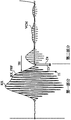
- Figure 1 is a waveform diagram of the output signal generated in the time domain when the transducer is triggered by an input signal.
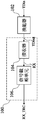
- FIG. 2 is a schematic diagram of an embodiment of a signal processing circuit of this application.
- FIG. 3 is a schematic diagram of an embodiment of the signal truncation module of this application.
- FIG. 4 is a waveform diagram of the first embodiment of the received signal after the signal truncation module generates a truncation according to the present application.
- FIG. 5 is a flowchart of the first embodiment of the signal truncation module of the present application to generate a truncated received signal.
- FIG. 6 is a waveform diagram of the received signal after truncation generated by the signal truncation module according to the first embodiment of the present application.
- FIG. 7 is a waveform diagram of the second embodiment of the received signal after the signal truncation module generates the truncated received signal.
- FIG. 8 is a flowchart of a second embodiment of the signal truncation module of the present application to generate a truncated received signal.
- FIG. 9 is a waveform diagram of the received signal after truncation generated by the signal truncation module according to the second embodiment of the present application.
- FIG. 10 is a schematic diagram of another embodiment of the signal truncation module of this application.
- FIG. 11 is a waveform diagram of a third embodiment of a received signal after the signal truncation module generates a truncation according to the present application.
- FIG. 12 is a flowchart of a third embodiment of the signal truncation module of the present application generating a truncated received signal.
- FIG. 13 is a waveform diagram of the received signal after truncation generated by the signal truncation module according to the third embodiment of the present application.
- FIG. 14 is a schematic diagram of another embodiment of the signal processing circuit of this application.
- first and second features are in direct contact with each other; and may also include additional components are formed between the first and second features, so that the first and second features may not be in direct contact.
- present disclosure may reuse component symbols and/or labels in multiple embodiments. Such repeated use is based on the purpose of brevity and clarity, and does not in itself represent the relationship between the different embodiments and/or configurations discussed.
- spatially relative terms here such as “below”, “below”, “below”, “above”, “above” and similar, may be used to facilitate the description of the drawing
- the relationship between one component or feature relative to another component or feature is shown.
- the original meaning of these spatially-relative vocabulary covers a variety of different orientations of the device in use or operation in addition to the orientation shown in the figure.
- the device may be placed in other orientations (for example, rotated by 90 degrees or in other orientations), and these spatially-relative description words should be explained accordingly.
- a transducer is a device that converts one form of energy into another form. These energy forms may include electrical energy, mechanical energy, electromagnetic energy, light energy, chemical energy, sound energy, and thermal energy, etc. This application is not limited to many, and the transducer may include any device capable of converting energy.
- the transducer receives the transducer input signal TDin and correspondingly generates the transducer output signal TDout.
- the generated transducer output signal TDout may have different degrees due to various reasons (such as channel effect, transducer energy residual, etc.) Please refer to Fig. 1.
- the upper part of Fig. 1 is the more ideal transducer output signal TDout, and the lower part of Fig. 1 is the less ideal transducer output signal TDout.
- the less ideal transducer output signal TDout is relatively scattered and not concentrated in the time domain, resulting in a longer overall length of the transducer output signal. Therefore, when performing subsequent signal processing, it is necessary to store more data for the output signal of the transducer, which results in a larger amount of calculation and consumes more hardware and power.
- FIG. 2 is a schematic diagram of an embodiment of the signal processing circuit 100 of this application.
- the signal processing circuit 100 is used to perform signal processing on the transducer output signal TDout, where the transducer output signal TDout is generated by the transducer 102 being triggered by the transducer input signal TDin at a first time point.
- the signal processing circuit 100 includes a receiver 104 and a signal truncation module 106.
- the receiver 104 is used for receiving the transducer output signal TDout and converting the received transducer output signal TDout into a receiving signal RXTDout.
- the receiver 104 may include an analog-to-digital converter to convert the transducer output signal TDout in analog form into the received signal RXTDout in digital form.
- the receiver 104 may include a low noise amplifier to provide sufficient gain to amplify the transducer output signal TDout.
- the signal truncation module 106 is coupled to the receiver 104 for generating a truncated received signal RX_TRC according to the received signal RX.
- the signal truncation module 106 of the embodiment of the present application divides the received signal RX into a first part and a second part, which are continuous and non-overlapping in the time domain, and then retain the first part of the received signal RX as much as possible, and reduce or eliminate Receive the second part of the signal RX to generate the truncated received signal.
- the generated truncated received signal RX_TRC also has a first part and a second part corresponding to the first part and the second part of the received signal RX, respectively.
- the first part and the second part of the truncated received signal RX_TRC are continuous and not in the time domain. Overlap.
- the time length of the first part of the received signal RX_TRC after truncation is the same as the time length of the first part of the received signal RX; the time length of the second part of the received signal RX_TRC after truncation is the same as the time length of the second part of the received signal RX .
- the amplitude of the first part of the received signal RX_TRC after truncation and the amplitude of the first part of the received signal RX are in a fixed multiple relationship; the amplitude of the second part of the received signal RX_TRC after truncation The value and the amplitude of the second part of the received signal RX are in a non-fixed multiple relationship as a whole, or the amplitude of the second part of the received signal RX_TRC after truncation is equal to zero.
- the same means substantially the same, and fixed means substantially fixed, that is, within the acceptable standard error, all are substantially the same or substantially fixed, and the same description in the following description also applies.
- FIG. 3 is a schematic diagram of an embodiment of the signal truncation module 106 of this application.
- the signal truncation module 106 includes a contour extraction module 1062 and a signal processing module 1064.
- the profile capturing module 1062 is used to generate the received signal profile RX_PRF of the received signal RX according to the received signal RX.
- the signal processing module 1064 generates the truncated received signal RX_TRC according to the received signal RX, the received signal profile RX_PRF and the specific voltage TH.
- various embodiments of the signal processing module 1064 of the present application will be further described in conjunction with the figures.
- Steps 202 to 210 of FIG. 5 are a flowchart of the first embodiment of the signal truncation module 106 of the present application generating the truncated received signal RX_TRC.
- the profile capture module 1062 in the signal truncation module 106 generates the received signal profile RX_PRF of the received signal RX according to the received signal RX.
- the signal processing module 1064 generates the truncated received signal RX_TRC according to the received signal RX, the received signal profile RX_PRF and the specific voltage TH.
- the signal processing module 1064 sets the first time point when the received signal profile RX_PRF of the received signal RX reaches the specific voltage TH from top to bottom as the first time point T1, as shown in FIG. 4.
- the signal processing module 1064 sets the time point when the received signal RX passes the common mode voltage VCM for the first time after the first time point T1 as the second time point T2, as shown in FIG. 4.
- the signal processing module 1064 sets the part of the received signal RX before the second time point T2 as the first part and serves as the first part of the received signal RX_TRC after truncation, and sets the received signal RX at the second time
- the part after the point T2 is set as the second part and set as the common mode voltage VCM as the second part of the truncated received signal to obtain the truncated received signal RX_TRC as shown in FIG. 6.
- the multiple relationship between the amplitude of the first part of the received signal RX_TRC after truncation and the amplitude of the first part of the received signal RX is fixed to 1, but this application is not limited to this, and the received signal after truncation
- the multiple relationship between the amplitude of the second part of RX_TRC and the amplitude of the second part of the received signal RX is not fixed (or when the common mode voltage VCM is equal to 0V, the amplitude of the second part of the received signal RX_TRC after truncation is 0).
- the subsequent signal processing circuit does not need to store data for the second part of the received signal RX, thereby reducing the amount of calculation and the consumption of hardware and power.
- step 206 may also be changed.
- the signal processing module 1064 sets the time point when the received signal RX passed the common mode voltage VCM at the first time point T1 as the second time point T2; Or, for example, the signal processing module 1064 sets the time point when the received signal RX passes the common mode voltage VCM closest to the first time point T1 as the second time point T2.
- Steps 302 to 312 in FIG. 8 are a flowchart of a second embodiment of the signal truncation module 106 of the present application generating the truncated received signal RX_TRC.
- the profile capture module 1062 in the signal truncation module 106 generates the received signal profile RX_PRF of the received signal RX according to the received signal RX.
- the signal processing module 1064 generates the truncated received signal RX_TRC according to the received signal RX, the received signal profile RX_PRF and the specific voltage TH.
- step 304 for a signal group, the signal processing module 1064 sets the time point when the received signal profile RX_PRF of the received signal RX reaches the specific voltage TH from top to bottom as the first time point T1 (The same as the first embodiment in FIGS. 4 to 6), as shown in FIG. 7.
- step 306 the signal processing module 1064 sets the first turning point of the received signal RX from the top to the bottom after the first time point T1 as the third time point T3, and
- step 308 the signal processing module 1064 sets the time point when the received signal RX passes the common mode voltage VCM for the first time after the third time point T3 as the fourth time point T4, as shown in FIG. 7.
- the signal processing module 1064 sets the part of the received signal RX before the fourth time point T4 as the first part as the first part of the truncated received signal RX_TRC, and sets the received signal RX at the fourth time point T4.
- the following part is set as the second part and set as the common mode voltage VCM as the second part of the truncated received signal RX_TRC to obtain the truncated received signal RX_TRC as shown in FIG. 9.
- the multiple relationship between the amplitude of the first part of the received signal RX_TRC after truncation and the amplitude of the first part of the received signal RX is fixed to 1, but this application is not limited to this, and the received signal after truncation
- the multiple relationship between the amplitude of the second part of RX_TRC and the amplitude of the second part of the received signal RX is not fixed (or when the common mode voltage VCM is equal to 0V, the amplitude of the second part of the received signal RX is 0).
- the subsequent signal processing circuit does not need to store data for the second part of the received signal RX, thereby reducing the amount of calculation and the consumption of hardware and power.
- FIG. 10 is a schematic diagram of another embodiment of the signal truncation module 106 of this application.
- the signal processing module 2064 of FIG. 10 generates the truncated received signal RX_TRC according to the received signal RX, the received signal profile RX_PRF, the specific voltage TH, and the first specific window WD1.
- the embodiment of the signal processing module 2064 of the present application will be further described in conjunction with figures.
- FIG. 11 and FIG. 13 are waveform diagrams of the third embodiment of the received signal RX_TRC after the signal truncation module 106 generates the truncation of the application.
- Steps 402 to 412 in FIG. 12 are flowcharts of the third embodiment in which the application signal truncation module 106 generates the truncated received signal RX_TRC.
- the profile capture module 1062 in the signal truncation module 106 generates the received signal profile RX_PRF of the received signal RX according to the received signal RX.
- the signal processing module 2064 generates the truncated received signal RX_TRC according to the received signal RX, the received signal profile RX_PRF, the specific voltage TH, and the first specific window WD1.
- the first specific window WD1 corresponds to the received signal RX, as shown in FIG. 11.
- the first specific window WD1 can be any window function such as Hanning window, Blackman-Harris window, etc.
- the signal processing module 2064 sets the time point when the received signal profile RX_PRF of the received signal RX reaches the specific voltage TH from top to bottom as the first time point T1, as shown in FIG. 11 Shown.
- the signal processing module 2064 sets the time when the first specific window WD1 reaches the specific voltage TH from top to bottom for the first time as the fifth time point T5.
- the signal processing module 2064 generates a second specific window WD2 corresponding to the first specific window WD1.
- the second specific window WD2 and the first specific window WD1 have the same time length.
- the size unit of the first specific window WD1 is voltage
- the second specific window WD2 is shown in FIG. 11 together with the received signal RX and the first specific window WD1, the second specific window WD1
- the value of the window WD2 represents the ratio rather than the voltage.
- the value of the second specific window WD2 before the first time point T1 is set as the first constant.
- the first constant is 1, and the value in the first After the time point T1, the value of the second specific window WD2 decreases from the first constant to a second constant, and in this embodiment, the second constant is zero.
- the signal processing module 2064 determines that the second specific window WD2 is after the first time point T1 according to the portion of the first specific window WD1 between the fifth time point T5 and the end time point Tend of the first specific window WD1 in step 410 part. For example, the amplitude of the first specific window WD1 at the end time point Tend has converged to the common mode voltage VCM, so the part of the first specific window WD1 after the fifth time point T5 to the end time point Tend is supplemented to the common mode
- the voltage VCM extends to the sixth time point T6, so that the time length from the fifth time point T5 to the sixth time point T6 is equal to the time length from the first time point T1 to the end time point Tend.
- the part between the fifth time point T5 and the sixth time point T6 using the first specific window WD1 is linearly expanded to the part between the first time point T1 and the end time point Tend of the second specific window WD2.
- dividing the portion of the first specific window WD1 between the fifth time point T5 and the sixth time point T6 by the specific voltage TH is regarded as the second specific window WD2 between the first time point T1 and the end time point Tend. section.
- step 412 the signal processing module 2064 multiplies the second specific window WD2 and the received signal RX to obtain the truncated received signal RX_TRC.
- the received signal RX is the first part before the first time point T1
- the received signal RX is the second part after the first time point T1. It can be seen from FIG.
- the multiple relationship between the amplitude of the first part of the received signal RX_TRC after truncation and the amplitude of the corresponding first part of the received signal RX is fixed to the first constant, which is 1 in this embodiment, and truncated Afterwards, the multiple relationship between the amplitude of the second part of the received signal RX_TRC and the amplitude of the second part of the corresponding signal group of the received signal RX is not fixed, that is, from the first constant to the second constant, in this embodiment from 1 is reduced to 0, so it can be seen that the amplitude of the second part of the received signal RX_TRC after truncation in FIG. 13 is not the same as the amplitude of the second part of the received signal RX in FIG.
- the length of the truncated received signal RX_TRC to be processed by the subsequent signal processing circuit is shorter than that of the received signal RX, so there is no need to store data for all of the received signal RX, thereby reducing the amount of calculation and hardware And power consumption.
- FIG. 14 is a schematic diagram of an embodiment of the signal processing circuit 200 of this application.
- the signal processing module 200 further includes a cross-correlation calculation module 108.
- the cross-correlation calculation module 108 may be used to perform cross-correlation calculation on the truncated received signal RX_TRC generated by the received signal RX at two different times of the received signal RX, to determine the time difference between the two received signals.
- the transducer 102 is triggered by the first transducer input signal TDin1 and the second transducer input signal TDin2 at the first time point and the second time point, respectively, to generate the first transducer output signal TDout1 and the second transducer output signal TDout1.
- the receiver 104 receives the first transducer output signal TDout1 and the second transducer output signal TDout2 and converts them into the first received signal RX1 and the second received signal RX2 respectively.
- the signal truncation module 106 is based on the first The receiving signal RX1 and the second receiving signal RX2 respectively generate a first truncated receiving signal RX_TRC1 and a second truncated receiving signal RX_TRC2.
- the cross-correlation calculation module 108 performs cross-correlation calculation on the first truncated received signal RX_TRC1 and the second truncated received signal RX_TRC2 to determine the time difference between the first time point and the second time point.
- the present application also provides a chip, which includes a signal processing circuit 100 or a signal processing circuit 200.
- the signal processing circuit 100/200 may be applied to a sensor device.
- the present application also provides a flow meter, which includes the signal processing circuit 100/200 and the transducer 102.
- the above-mentioned flow meter can be used to sense the flow rate and/or flow rate of gas and liquid, but the application is not limited thereto.
Landscapes
- Physics & Mathematics (AREA)
- General Physics & Mathematics (AREA)
- Engineering & Computer Science (AREA)
- Fluid Mechanics (AREA)
- Radar, Positioning & Navigation (AREA)
- Remote Sensing (AREA)
- Electromagnetism (AREA)
- Computer Networks & Wireless Communication (AREA)
- Acoustics & Sound (AREA)
- Thermal Sciences (AREA)
- Mechanical Engineering (AREA)
- Measuring Volume Flow (AREA)
- Arrangements For Transmission Of Measured Signals (AREA)
Priority Applications (5)
| Application Number | Priority Date | Filing Date | Title |
|---|---|---|---|
| EP19886075.1A EP3712571A4 (en) | 2019-02-01 | 2019-02-01 | SIGNAL PROCESSING CIRCUIT, ASSOCIATED CHIP, FLOW METER AND PROCESS |
| JP2020533739A JP6908790B2 (ja) | 2019-02-01 | 2019-02-01 | 信号処理回路と、関連するチップ、流量計および方法 |
| PCT/CN2019/074369 WO2020155086A1 (zh) | 2019-02-01 | 2019-02-01 | 信号处理电路以及相关芯片、流量计及方法 |
| CN201980000240.2A CN109923783B (zh) | 2019-02-01 | 2019-02-01 | 信号处理电路以及相关芯片、流量计及方法 |
| US16/879,614 US20200278228A1 (en) | 2019-02-01 | 2020-05-20 | Signal processing circuit and related chip, flow meter and method |
Applications Claiming Priority (1)
| Application Number | Priority Date | Filing Date | Title |
|---|---|---|---|
| PCT/CN2019/074369 WO2020155086A1 (zh) | 2019-02-01 | 2019-02-01 | 信号处理电路以及相关芯片、流量计及方法 |
Related Child Applications (1)
| Application Number | Title | Priority Date | Filing Date |
|---|---|---|---|
| US16/879,614 Continuation US20200278228A1 (en) | 2019-02-01 | 2020-05-20 | Signal processing circuit and related chip, flow meter and method |
Publications (1)
| Publication Number | Publication Date |
|---|---|
| WO2020155086A1 true WO2020155086A1 (zh) | 2020-08-06 |
Family
ID=66979117
Family Applications (1)
| Application Number | Title | Priority Date | Filing Date |
|---|---|---|---|
| PCT/CN2019/074369 Ceased WO2020155086A1 (zh) | 2019-02-01 | 2019-02-01 | 信号处理电路以及相关芯片、流量计及方法 |
Country Status (5)
| Country | Link |
|---|---|
| US (1) | US20200278228A1 (https=) |
| EP (1) | EP3712571A4 (https=) |
| JP (1) | JP6908790B2 (https=) |
| CN (1) | CN109923783B (https=) |
| WO (1) | WO2020155086A1 (https=) |
Families Citing this family (2)
| Publication number | Priority date | Publication date | Assignee | Title |
|---|---|---|---|---|
| CN110987099B (zh) * | 2019-11-15 | 2021-08-10 | 深圳市汇顶科技股份有限公司 | 流速侦测电路以及相关芯片以及流量计 |
| JP7026820B2 (ja) | 2019-11-15 | 2022-02-28 | シェンチェン グディックス テクノロジー カンパニー,リミテッド | 流速検出回路および関連するチップ及び流速計 |
Citations (3)
| Publication number | Priority date | Publication date | Assignee | Title |
|---|---|---|---|---|
| EP0312224A1 (en) * | 1987-09-30 | 1989-04-19 | Panametrics, Inc. | Differential correlation analyzer |
| CN1332841A (zh) * | 1998-12-29 | 2002-01-23 | 施蓝姆伯格工业公司 | 一种包括西格码-德尔他带通模-数转换器的超声流体流动速率测量方法和装置 |
| CN106855424A (zh) * | 2015-12-09 | 2017-06-16 | 德克萨斯仪器股份有限公司 | 使用接收信号的窗口化的超声流量计 |
Family Cites Families (10)
| Publication number | Priority date | Publication date | Assignee | Title |
|---|---|---|---|---|
| US6895267B2 (en) * | 2001-10-24 | 2005-05-17 | Scimed Life Systems, Inc. | Systems and methods for guiding and locating functional elements on medical devices positioned in a body |
| US7634328B2 (en) * | 2004-01-20 | 2009-12-15 | Masoud Medizade | Method, system and computer program product for monitoring and optimizing fluid extraction from geologic strata |
| US7117104B2 (en) * | 2004-06-28 | 2006-10-03 | Celerity, Inc. | Ultrasonic liquid flow controller |
| HUP0700785A2 (en) * | 2007-12-05 | 2009-06-29 | Thormed Kft | Method and apparatus for determining the flow parameters of a streaming medium |
| US8220584B2 (en) * | 2009-05-18 | 2012-07-17 | Magnetrol International, Incorporated | Hybrid level measurement system |
| WO2013017969A1 (en) * | 2011-08-04 | 2013-02-07 | Sik- The Swedish Institute For Food And Biotechnology | Fluid visualisation and characterisation system and method; a transducer |
| US9689726B2 (en) * | 2012-07-09 | 2017-06-27 | Texas Instruments Incorporated | Flow meter |
| JP2014085254A (ja) * | 2012-10-24 | 2014-05-12 | Asahi Organic Chemicals Industry Co Ltd | 超音波流量計及びこれを備える流体制御装置 |
| PL3234514T3 (pl) * | 2015-08-28 | 2020-07-27 | Reliance Worldwide Corporation | Konfiguracja i kalibracja przepływomierza |
| DE102016118421A1 (de) * | 2016-09-29 | 2018-03-29 | Sick Ag | Lokalisieren eines Ereignisses in einem Sensorsignal |
-
2019
- 2019-02-01 JP JP2020533739A patent/JP6908790B2/ja not_active Expired - Fee Related
- 2019-02-01 WO PCT/CN2019/074369 patent/WO2020155086A1/zh not_active Ceased
- 2019-02-01 EP EP19886075.1A patent/EP3712571A4/en not_active Withdrawn
- 2019-02-01 CN CN201980000240.2A patent/CN109923783B/zh active Active
-
2020
- 2020-05-20 US US16/879,614 patent/US20200278228A1/en not_active Abandoned
Patent Citations (3)
| Publication number | Priority date | Publication date | Assignee | Title |
|---|---|---|---|---|
| EP0312224A1 (en) * | 1987-09-30 | 1989-04-19 | Panametrics, Inc. | Differential correlation analyzer |
| CN1332841A (zh) * | 1998-12-29 | 2002-01-23 | 施蓝姆伯格工业公司 | 一种包括西格码-德尔他带通模-数转换器的超声流体流动速率测量方法和装置 |
| CN106855424A (zh) * | 2015-12-09 | 2017-06-16 | 德克萨斯仪器股份有限公司 | 使用接收信号的窗口化的超声流量计 |
Non-Patent Citations (2)
| Title |
|---|
| See also references of EP3712571A4 * |
| YAN PING;LI JIPING: "Signal Processing of Ultrasonic Flowmeter Based on SST", BULLETIN OF SCIENCE AND TECHNOLOGY, vol. 33, no. 12, 22 December 2017 (2017-12-22), pages 91 - 95,186, XP009522529, ISSN: 1001-7119, DOI: 10.13774/j.cnki.kjtb.2017.12.018 * |
Also Published As
| Publication number | Publication date |
|---|---|
| JP6908790B2 (ja) | 2021-07-28 |
| CN109923783B (zh) | 2023-05-30 |
| CN109923783A (zh) | 2019-06-21 |
| JP2021514459A (ja) | 2021-06-10 |
| US20200278228A1 (en) | 2020-09-03 |
| EP3712571A4 (en) | 2021-01-20 |
| EP3712571A1 (en) | 2020-09-23 |
Similar Documents
| Publication | Publication Date | Title |
|---|---|---|
| JP6909289B2 (ja) | デジタルにオーバーサンプリングされるセンサシステムにおける時間遅延、装置及び方法 | |
| US9467774B2 (en) | System and method for a PCM interface for a capacitive signal source | |
| CN104316737B (zh) | 一种基于fpga幅度偏置可调的波形发生电路及方法 | |
| US9722561B2 (en) | Systems and apparatus providing frequency shaping for microphone devices and methods of operation of the same | |
| US10917103B2 (en) | Analog-to-digital converter device and method for calibrating clock skew | |
| WO2020155086A1 (zh) | 信号处理电路以及相关芯片、流量计及方法 | |
| US20200378813A1 (en) | Calibration circuit and associated signal processing circuit and chip | |
| WO2020033772A1 (en) | Capacitive mems microphone with built-in self-test | |
| Samoylov et al. | Estimation to efficiency of the using of anti-alias filter in the A/D interface of instrumentation and control systems | |
| WO2018120612A1 (zh) | 一种数据采样方法、芯片和计算机存储介质 | |
| CN109104169B (zh) | 一种并行架构高速三角波信号发生器的信号合成方法 | |
| CN102055438A (zh) | 一种高速方波生成装置及方法 | |
| JP2021514459A5 (https=) | ||
| CN204272043U (zh) | 一种用于声源定位装置的信号预处理模块 | |
| Malek | Blind compensation of memoryless nonlinear distortions in sparse signals | |
| Parker | Correspondence-apodization and windowing eigenfunctions | |
| CN101303610B (zh) | 用于信号发生器取样步长复杂多变的信号离散方法 | |
| CN106209033A (zh) | 相位差调节电路 | |
| JP6565488B2 (ja) | 差動信号をシングルエンド信号に変換する回路及び方法 | |
| WO2018131725A4 (en) | D/a conversion device, method, storage medium, electronic musical instrument, and information processing apparatus | |
| CN109923782B (zh) | 信号产生电路以及相关芯片、流量计及方法 | |
| CN112312270B (zh) | 基于计算机声卡的音频频响和相位测试方法及装置 | |
| US9203388B2 (en) | Method for generating clock for system operating at rising edge | |
| US6515466B2 (en) | Phase comparator | |
| JP4143703B2 (ja) | デジタル演算処理方法 |
Legal Events
| Date | Code | Title | Description |
|---|---|---|---|
| ENP | Entry into the national phase |
Ref document number: 2020533739 Country of ref document: JP Kind code of ref document: A |
|
| ENP | Entry into the national phase |
Ref document number: 2019886075 Country of ref document: EP Effective date: 20200616 |
|
| 121 | Ep: the epo has been informed by wipo that ep was designated in this application |
Ref document number: 19886075 Country of ref document: EP Kind code of ref document: A1 |
|
| NENP | Non-entry into the national phase |
Ref country code: DE |