WO2020153496A1 - 鉄道車両用制輪子の取付構造及び制輪子ブロック - Google Patents
鉄道車両用制輪子の取付構造及び制輪子ブロック Download PDFInfo
- Publication number
- WO2020153496A1 WO2020153496A1 PCT/JP2020/002609 JP2020002609W WO2020153496A1 WO 2020153496 A1 WO2020153496 A1 WO 2020153496A1 JP 2020002609 W JP2020002609 W JP 2020002609W WO 2020153496 A1 WO2020153496 A1 WO 2020153496A1
- Authority
- WO
- WIPO (PCT)
- Prior art keywords
- brake shoe
- mounting structure
- expansion
- block
- movable member
- Prior art date
- Legal status (The legal status is an assumption and is not a legal conclusion. Google has not performed a legal analysis and makes no representation as to the accuracy of the status listed.)
- Ceased
Links
Images






Classifications
-
- B—PERFORMING OPERATIONS; TRANSPORTING
- B61—RAILWAYS
- B61H—BRAKES OR OTHER RETARDING DEVICES SPECIALLY ADAPTED FOR RAIL VEHICLES; ARRANGEMENT OR DISPOSITION THEREOF IN RAIL VEHICLES
- B61H1/00—Applications or arrangements of brakes with a braking member or members co-operating with the periphery of the wheel rim, a drum or the like
-
- F—MECHANICAL ENGINEERING; LIGHTING; HEATING; WEAPONS; BLASTING
- F16—ENGINEERING ELEMENTS AND UNITS; GENERAL MEASURES FOR PRODUCING AND MAINTAINING EFFECTIVE FUNCTIONING OF MACHINES OR INSTALLATIONS; THERMAL INSULATION IN GENERAL
- F16D—COUPLINGS FOR TRANSMITTING ROTATION; CLUTCHES; BRAKES
- F16D65/00—Parts or details
- F16D65/02—Braking members; Mounting thereof
- F16D65/04—Bands, shoes or pads; Pivots or supporting members therefor
- F16D65/06—Bands, shoes or pads; Pivots or supporting members therefor for externally-engaging brakes
Definitions
- the present invention relates to a brake shoe mounting structure and a brake shoe block for railway vehicles.
- a brake shoe As a brake mechanism for railway vehicles, there is a tread system that is often used in conventional lines. In this tread system, a brake shoe is pressed against the tread surface of a wheel to obtain a braking force.
- a plurality of cast iron blocks are detachably provided by bolts and nuts on a back plate (base metal) formed in an arc shape from a material having elasticity. Therefore, for example, when the cast iron block is worn, it is not necessary to replace the brake shoe itself, and only the cast iron block can be replaced and the back plate can be used. Therefore, the cost for replacing the brake shoe can be reduced.
- the brake shoe attachment device of Patent Document 2 is simple in that the slider is fitted to the slider holder to which the pin is connected in advance, and the pin is rotated so that its free end is locked in the pin receiving recess. By performing various operations, the slider can be attached to the slider holder.
- the friction material is specialized in cast iron, and it cannot be applied to sintered alloys or low hardness resins.
- the fixing structure to the brake shoe head requires a back plate (base metal) as in the conventional case, and does not reduce the risk of vibration due to rattling.
- the brake shoe attachment device of Patent Document 2 since the brake shoe attachment device of Patent Document 2 has many thin plates or thin rod-shaped parts, it may be damaged by impact during transportation or flying objects (pebbles, etc.) during traveling. Moreover, since the number of parts is large, maintainability is poor.
- the present invention has been made in view of the above circumstances, and an object thereof is to combine friction materials of different materials, and by fixing without rattling, it is possible to reduce noise due to vibration and wear of parts, and An object of the present invention is to provide a railroad vehicle brake shoe mounting structure and a brake shoe block that can be manufactured, replaced, and maintained easily with simple parts.
- an expansion holding mechanism that is provided at an intermediate portion of the brake shoe head in the wheel rotation direction, and holds the expanded brake block in a state in which it is pressed in a direction in which the interval between the expansion side edges of the brake shoe block is expanded.
- An expansion holding mechanism that is provided at an intermediate portion of the brake shoe head in the wheel rotation direction, and holds the expanded brake block in a state in which it is pressed in a direction in which the interval between the expansion side edges of the brake shoe block is expanded.
- the brake shoe block is directly fixed to the brake shoe head.
- a friction material is fixed to one surface of a reinforcing plate formed of a rectangular flat steel plate.
- the reinforcing plate can be combined with friction materials having different properties by unifying the shapes of the steel plates.
- the friction material having a high hardness (cast iron is a base) is specialized, but according to the mounting structure of the railway vehicle brake shoe of this configuration, even a material having a low hardness such as a resin can be used. Correspondence becomes possible easily.
- a pair of brake shoe blocks arranged in a row in the brake shoe head along the tread surface of the wheel is provided with an extension holding mechanism provided at an intermediate portion of the brake shoe head in the wheel rotation direction so that the gap between the extension side edges is increased. Is held pressed in the direction of expansion.
- the fixed side edge of the pair of brake shoe blocks whose intervals are expanded by the expansion holding mechanism is fixed to the respective positioning fixing portions at both ends of the brake shoe head in the wheel rotation direction. Since the expansion holding mechanism is arranged between the pair of brake shoe blocks, the set of brake shoe blocks can be fixed or released at the same time.
- a mounting structure for a railway vehicle brake shoe comprising: a misalignment preventing projection that is provided so as to project from a brake shoe head and restricts a mounting direction of the brake shoe block by engaging with the notch.
- the notch is formed at either end of the expansion-side edge. Any one of the ends on the extended side edge is one of the ends in the tread width direction.
- the tread width direction is a direction orthogonal to the circumferential direction of the tread of the wheel.
- the notch formed at one end engages with the misassembly preventing protrusion provided on the brake shoe head in correspondence with the notch. That is, the brake shoe block is attached so that the inside and outside of the wheel in the tread width direction and the inside and outside of the friction material in the tread width direction match.
- a structure for mounting a brake shoe for a railway vehicle comprising: a fixed-side protrusion that fits into a side recess.
- the fixed-side recess is formed at the fixed-side edge of the reinforcing plate.
- the fixed-side projection of the positioning and fixed portion fits into this fixed-side recess.
- the fixed-side protrusions are formed on positioning fixing portions provided at both ends of the brake shoe head in the wheel rotation direction.
- movement of the brake plate in the tread width direction with respect to the brake shoe head is restricted by fitting the fixed concave portion of the reinforcing plate with the fixed protrusion of the positioning fixing portion.
- a mounting structure for a railway vehicle brake shoe according to any one of (1) to (3) above, wherein the expansion-side concave portion formed on the expansion-side edge and the expansion holding mechanism are provided.
- a mounting structure for a brake shoe for a rail vehicle comprising: an expansion-side protrusion provided on a movable member and fitted into the expansion-side recess.
- the expansion-side recess is formed at the expansion-side edge of the reinforcing plate.
- the expansion side projection of the movable member of the expansion holding mechanism is fitted into the expansion side recess.
- the expansion side protrusion is formed on a movable member of the expansion holding mechanism supported by the brake shoe head.
- movement of the reinforcing plate in the tread width direction with respect to the brake shoe head is restricted by fitting the expansion concave portion of the reinforcing plate with the expansion protrusion of the movable member.
- a railway vehicle brake shoe including: a pair of movable members that are configured to be pressed in a direction in which the distance between the expansion-side edges is expanded and that are interposed between the pair of brake shoe blocks. Mounting structure.
- the expansion holding mechanism has the both-end screw members and the pair of movable members.
- the both-end screw member has a positive screw portion formed at one end and a reverse screw portion formed at the other end. In the screw members at both ends, one movable member is screwed into the positive screw portion, and the other movable member is screwed into the reverse screw portion.
- the both-end screw members are rotatably fixed to the brake shoe head, for example, in a direction along the vertical axis, and expand the interval between the expansion-side edges.
- This expansion holding mechanism can be referred to as bottom surface fixing.
- the bottom-fixed expansion holding mechanism can simultaneously rotate and lock a pair of brake block blocks vertically arranged by rotating both end screw members on the back face of the brake shoe head from below.
- the expansion holding mechanism includes the screw member, the first movable member, and the second movable member.
- the screw member has a screw portion formed at one end.
- the first movable member is screwed onto the threaded portion of the threaded member and engages with one of the adjacent expansion-side end edges.
- the second movable member is provided on the brake shoe head so as to be movable in the axial direction, engages with the other of the adjacent expansion-side end edges, and is pressed by one end of the screw member.
- the screw member is rotatably fixed to the brake shoe head, for example, in the direction along the vertical axis, and expands the interval between the expansion-side edges via the first movable member and the second movable member.
- This expansion holding mechanism can also be referred to as bottom surface fixing.
- the expansion holding mechanism that is fixed on the lower surface can rotate a screw member on the back surface of the brake shoe head from below to simultaneously fix and open a set of brake shoe blocks that are vertically arranged.
- the rotation of the second movable member about the axis with respect to the brake shoe head is restricted. Therefore, the brake shoe block whose expansion side edge is engaged by the second movable member is regulated in rotation about the axis of the second movable member, so that it is in a temporarily assembled state before completion of fixing by the expansion holding mechanism.
- the inclination of the brake shoe head is regulated, and the workability when fixed is improved.
- a wedge cam is integrally formed along the axial direction, and a cam movable member provided movably along a direction intersecting the wheel rotation direction with respect to the brake shoe head, and a pair of inclined surfaces of the wedge cam. Sliding slanting surfaces respectively formed on the expansion side edges so as to face each other and slidably contact with each other, and are screwed into the screw portion, and move the cam movable member axially forward and backward with respect to the brake shoe head.
- a railroad vehicle brake shoe mounting structure comprising: a rotating screw member.
- the expansion holding mechanism includes the cam movable member, the sliding inclined surfaces formed at the expansion side edges, and the rotary screw member.
- the cam movable member has a threaded portion formed at one end in the axial direction and a wedge cam integrally formed at the other end in the axial direction. It is provided so as to be movable in the width direction.
- the wedge cam has a pair of inclined surfaces that move toward and away from each other in the tread width direction. That is, the pair of inclined surfaces has a wedge shape.
- the slidable inclined surfaces are formed on the respective expansion-side end edges and are in sliding contact with the pair of inclined surfaces of the wedge cam.
- the rotary screw member is screwed onto the screw portion of the wedge shaft, and moves the cam movable member forward and backward with respect to the brake shoe head in the tread width direction, thereby expanding the interval between the expansion-side edges.
- This expansion holding mechanism can be referred to as side fixing because it rotates the rotary screw member arranged on the side surface of the brake shoe head.
- the side-fixed expansion holding mechanism can rotate and rotate the rotating screw member arranged on the side surface of the brake shoe head from the side surface of the brake shoe head to simultaneously fix and open a pair of brake shoe blocks arranged vertically in a row. it can.
- a set of brake block in which a friction material is fixed to one surface of a reinforcing plate formed in the shape of a rectangular flat plate, and the brake block is vertically arranged along the tread surface of the wheel, the set of block blocks
- a brake shoe block in which a concave portion is formed on at least one edge of the adjacent extended side edge of the reinforcing plate and at least one fixed side edge opposite to the extended side edge.
- the concave portion is provided on at least one of the adjacent extended side edge of the reinforcing plate and the fixed side edge opposite to the extended side edge. It is formed.
- the brake head or the protrusion of the expansion holding mechanism is fitted into this recess.
- movement of the wheel in the tread width direction is restricted by fitting the recess of the reinforcing plate with the protrusion.
- notches are formed at both ends of the wheel flange side of the reinforcing plate of the brake shoe block.
- the notch engages a misassembly preventing protrusion provided on the brake shoe head.
- the brake shoe block is attached so that the inside and outside of the wheel in the tread width direction and the inside and outside of the friction material in the tread width direction match. As a result, the brake shoe block is prevented from being erroneously assembled in which the pressure contact surface gradient of the friction material is opposite to the tread surface gradient of the wheel.
- the mounting structure of the railway vehicle brake shoe according to the present invention it is possible to combine friction materials of different materials, and by fixing without friction, it is possible to reduce noise due to vibration and wear of the parts, and Can be made into a simple shape to facilitate manufacturing, replacement and maintenance.
- the reinforcing plate and the friction material can have a simple shape to facilitate manufacturing, replacement, and maintenance.
- FIG. 1 is a perspective view showing a mounting structure of a railway vehicle brake shoe according to a first embodiment of the present invention.
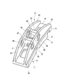
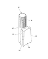
- FIG. 2 is a perspective view of the brake shoe block shown in FIG.
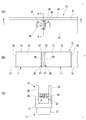
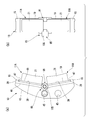
- FIG. 3A is a rear view of the mounting structure for the railway vehicle brake shoe shown in FIG. 1, viewed from the brake shoe head side
- FIG. 3B is a front view of the mounting structure viewed from the friction material side
- 3C is a bottom view of the same mounting structure as seen from the lower end side of the brake shoe head.
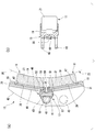
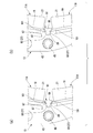
- 4A is a sectional view taken along the line AA of FIG. 3A
- FIG. 4B is a sectional view taken along the line BB of FIG.
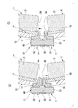
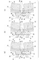
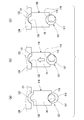
- FIG. 5(a) and 5(b) are operation explanatory views when adjusting the gap of the expansion holding mechanism in the mounting structure according to the first embodiment of the present invention.
- FIG. 6 is a perspective view showing a mounting structure for a railway vehicle brake shoe according to a second embodiment of the present invention.
- FIG. 7 is an exploded perspective view showing a mounting structure of the railway vehicle brake shoe shown in FIG. 8A is a vertical cross-sectional view showing a mounting structure according to the second embodiment of the present invention
- FIG. 8B is an exploded perspective view of the expansion holding mechanism shown in FIG. 8A.
- 9(a), 9(b), and 9(c) are operation explanatory views when adjusting the gap of the expansion holding mechanism in the mounting structure according to the second embodiment of the present invention.
- FIG. 10A is a side view showing a mounting structure for a railway vehicle brake shoe according to a third embodiment of the present invention
- FIG. 10B is a front view of FIG. 10A viewed from the friction material side.
- It is a figure. 11 is a perspective view of the cam movable member shown in FIG. 12(a) and 12(b) are operation explanatory views when adjusting the gap of the expansion holding mechanism in the mounting structure according to the third embodiment.
- 13(a) and 13(b) are enlarged views of main parts corresponding to FIGS. 12(a) and 12(b).
- FIG. 14A is a rear view of the railway vehicle brake shoe mounting structure according to the reference example as viewed from the brake shoe head side
- FIG. 14B is a side view of the mounting structure
- FIG. 3 is a front view of the same mounting structure as seen from the friction material side.
- 15A is a bottom view of the mounting structure for the railway vehicle brake shoe shown in FIG. 14 as seen from the lower end side of the brake shoe head, and FIG. 15B is CC of FIG. 15A.
- 16(a) is a perspective view of the brake shoe block shown in FIG. 14
- FIG. 16(b) is a perspective view of the rotary screw member shown in FIG.
- FIG. 16(c) is shown in FIG. It is a perspective view of an eccentric shaft.
- 17(a), (b), and (c) are operation explanatory views at the time of adjusting the clearance of the mounting structure of the railway vehicle brake shoe according to the reference example.
- FIG. 1 is a perspective view showing a mounting structure of a railway vehicle brake shoe according to a first embodiment of the present invention.
- the railway vehicle brake shoe mounting structure according to the present embodiment mainly includes a brake shoe block 11, a brake shoe head 13, a positioning fixing portion 15, and an extension holding mechanism 17.
- a brake shoe block 11 mainly includes a brake shoe block 11, a brake shoe head 13, a positioning fixing portion 15, and an extension holding mechanism 17.
- FIG. 2 is a perspective view of the brake shoe block 11 shown in FIG.
- the brake shoe block 11 has a friction material 21 fixed to one surface of a reinforcing plate 19 formed in a rectangular flat plate shape.
- the wheel-side sliding surface (pressure contact surface) of the friction material 21 is formed in a surface shape that matches the tread surface 25 (see FIG. 4) of the wheel 23.
- the reinforcing plate 19 is made of a steel plate and is formed of a simple rectangular flat plate.
- the friction material 21 can be made of sintered alloy or resin.
- a base metal is required to fix the brake shoe block to the brake shoe head, but the brake shoe block 11 of this mounting structure is directly attached to the brake shoe head 13 and the steel plate on the back surface. (That is, the reinforcing plate 19) is fixed.
- the brake shoe blocks 11 are arranged in a row in the brake shoe head 13 along the tread surface 25 of the wheel 23 (see FIG. 4).
- a recess is formed in at least one of the extended side edge 27 and the fixed side edge 29 opposite to the extended side edge 27 of the reinforcing plate 19 in the pair of brake shoe blocks 11.
- the recesses are formed as the expansion-side recess 33 and the fixed-side recess 31 on both the expansion-side edge 27 and the fixed-side edge 29.
- the fixed-side concave portion 31 is formed on the fixed-side edge 29 of the reinforcing plate 19. Further, the expansion-side concave portion 33 is formed on the expansion-side edge 27 of the reinforcing plate 19.
- the fixed-side concave portion 31 fits into a fixed-side protruding portion 47 of the positioning fixing portion 15 described later.
- the expansion-side concave portion 33 is fitted with the expansion-side protrusion 59 of a movable member (a positive screw movable member 61 and a reverse screw movable member 63) provided in the expansion holding mechanism 17 described later.
- the railroad vehicle brake shoe attachment structure includes a notch 35 in the reinforcing plate 19 and a misassembly preventing projection 37 (see FIG. 3) on the brake shoe head 13.
- the notch 35 is formed at any one end of the extension side edge 27 (in the first embodiment, the end on the wheel flange side in the tread width direction).
- the misassembly preventing protrusion 37 is provided on the brake shoe head 13 so as to correspond to the notch 35.
- the misassembly preventing protrusion 37 restricts the mounting direction of the brake shoe block 11 by engaging with the notch 35.
- FIG. 3A is a rear view of the mounting structure for the railway vehicle brake shoe shown in FIG. 1 as seen from the brake shoe head 13 side
- FIG. 3B is the same mounting structure as seen from the friction material 21 side
- a front view and FIG. 3C are bottom views of the same mounting structure as seen from the lower end side of the brake shoe head 13.
- the brake shoe head 13 holds a set of brake shoe blocks 11 as shown in FIGS. 1 and 3. That is, the brake shoe head 13 has a set of brake shoe blocks 11 arranged in a row along the tread surface 25 of the wheel 23.
- a mounting surface 39 (see FIG. 4) for mounting the brake shoe block 11 is formed by a plane parallel to the reinforcing plate 19.
- the brake shoe head 13 is swingably attached to a non-rotating member (for example, a brake lever) supported by a bogie frame of a railway vehicle using a mounting hole 45 formed in the side plate portion 43 by a pin.
- a non-rotating member for example, a brake lever
- FIG. 4A is a sectional view taken along the line AA of FIG. 3, and FIG. 4B is a sectional view taken along the line BB of FIG.
- the brake shoe head 13 has positioning fixing portions 15 at both ends in the wheel rotation direction.
- the positioning fixing portion 15 has a space parallel to the mounting surface 39 into which the fixed side edge 29 is inserted.
- the respective positioning and fixing portions 15 position and fix the adjoining extended side edges 27 of the reinforcing plates 19 of the pair of brake shoe blocks 11 and the fixed side edge 29 on the opposite side.
- the stationary fixing portion 15 of the brake shoe head 13 is provided with a fixed side protrusion 47.
- the fixed-side protrusion 47 is located in the gap of the positioning fixing portion 15 and fits into the fixed-side recess 31 of the reinforcing plate 19. That is, the brake shoe block 11 is configured such that the pair of fixed-side end edges 29 that face each other with the fixed-side recess 31 sandwiched therebetween are inserted into the pair of voids that sandwich the fixed-side protrusion 47.
- An expansion holding mechanism 17 is provided at an intermediate portion of the brake shoe head 13 in the wheel rotation direction.
- the expansion holding mechanism 17 holds the space between the expansion-side edges 27 of the pair of brake shoe blocks 11 in a state of being pressed in a direction in which the expansion-side edges 27 are expanded.
- the expansion holding mechanism 17 has a screw member 49 at both ends and a pair of movable members.
- the both-end screw member 49 has a positive screw portion 51 and a reverse screw portion 53 formed at both ends in the axial direction.
- the both-end screw members 49 are provided so as to be movable and relatively rotatable in the wheel rotation direction (more accurately, in the vertical direction parallel to the tangent to the wheel 23) with respect to the brake shoe head 13.
- the both-end screw members 49 are rotatably fixed to the brake shoe head 13 by a shaft stopper plate 55.
- a hexagonal wrench hole 57 is formed on one end surface of the both-end screw member 49.
- the both-end screw member 49 is rotatably attached to the brake shoe head 13 with the hexagon wrench hole 57 facing downward.
- the set of movable members is interposed between the set of brake shoe blocks 11.
- the pair of movable members are configured to press in the direction in which the interval between the expansion-side edges is expanded by being screwed into the positive screw portion 51 and the reverse screw portion 53, respectively.
- An expansion-side protrusion 59 is provided on each of the pair of movable members. The expansion-side protrusion 59 is fitted in the expansion-side recess 33 of the reinforcing plate 19 in the same manner as the fixed-side protrusion 47.
- one set of the movable members is a positive screw movable member 61 having a positive screw portion 51 formed therein and the other is provided with a reverse screw portion 53 so that the movable member can be screwed into both end portions of the both-end screw member 49. It becomes the reverse screw movable member 63.
- FIGS. 5A and 5B are operation explanatory views when adjusting the gap of the expansion holding mechanism 17 in the mounting structure according to the first embodiment of the present invention.
- each fixed-side edge 29 is engaged with the positioning fixing portion 15 of the brake shoe head 13, and as shown in FIG. 27 is temporarily assembled by being engaged with the positive screw movable member 61 and the reverse screw movable member 63.
- the brake shoe block 11 does not fall off, but there is a gap between the movable member and the expansion side edge 27.
- the brake shoe block 11 is directly fixed to the brake shoe head 13.
- a friction material 21 is fixed to one surface of a reinforcing plate 19 formed of a rectangular flat steel plate.
- the reinforcing plate 19 can be combined with friction materials 21 having different properties by unifying the shapes of the steel plates.
- the friction material having high hardness (cast iron is the base) is specialized, but in the mounting structure of the railway vehicle brake shoe of the first embodiment, a low hardness material such as resin is used. Can be easily handled.
- a pair of brake shoe blocks 11 arranged in a row in the brake shoe head 13 along the tread surface 25 of the wheel 23 is expanded by an expansion holding mechanism 17 provided at an intermediate portion of the brake shoe head 13 in the wheel rotation direction.
- the side edges 27 are held in a state of being pressed in a direction of expanding the space between them.
- the fixed side edges 29 are fixed to the respective positioning fixing portions 15 at both ends of the brake shoe head 13 in the wheel rotation direction.
- the expansion holding mechanism 17 is arranged between the pair of brake shoe blocks 11 so that the set of brake shoe blocks 11 can be fixed or opened at the same time.
- a screw tightening mechanism having a simple structure or a shaft rotating mechanism can be adopted.
- the mounting structure for the railway vehicle brake shoe according to the first embodiment can simultaneously complete the fixing of the pair of brake shoe blocks 11 by a simple operation such as rotating the shaft or tightening the screws. it can. Further, it is possible to cope with a change in the fixed position due to a variation in dimensions, and it is possible to perform the fixing without rattling. Then, a set of brake shoe blocks 11 can be simultaneously opened and removed by a simple operation such as rotating the shaft or loosening the screw.
- the notch 35 has one end of the expansion-side edge 27 (in the first embodiment, the wheel flange in the tread width direction). Side end). One of the ends of the extended side edge 27 is one of the ends in the tread width direction.
- the tread width direction is a direction orthogonal to the circumferential direction of the tread 25 of the wheel 23.
- the notch 35 formed at one end (the end on the wheel flange side in the widthwise direction of the tread) is engaged with the misassembly preventing projection 37 provided on the brake shoe head 13 so as to correspond to the notch 35.
- the brake shoe block 11 is attached so that the inside and outside of the wheel 23 in the tread width direction and the inside and outside of the friction material 21 in the tread width direction coincide with each other.
- the tread 25 of the wheel 23 is provided with a tread to steer the wheel axle in a curve.
- the tread slope is an inclined surface that is inclined in the vertical direction from one side of the rail to the other side in the cross section of the rail.
- the pressure contact surface of the friction material 21 also has a pressure contact surface slope that follows the tread slope.
- the brake shoe block 11 has the erroneous assembly preventing projection 37 so that the friction material 21 is mounted inside and outside in the tread width direction in the tread width direction. Is regulated to match the direction of. Therefore, it is possible to prevent erroneous assembly in which the pressure contact surface gradient is opposite to the tread surface gradient.
- the fixed-side concave portion 31 is formed in the fixed-side edge 29 of the reinforcing plate 19.
- the 15 fixed-side protrusions 47 of the positioning and fixing portion are fitted into the fixed-side recess 31.
- the fixed-side protrusions 47 are formed on the positioning fixing portions 15 provided on both ends of the brake shoe head 13 in the wheel rotation direction.
- the fixed concave portion 31 of the reinforcing plate 19 is fitted into the fixed protrusion 47 of the positioning fixing portion 15, whereby movement of the brake shoe block 11 with respect to the brake shoe head 13 in the tread width direction is restricted.
- the expansion-side concave portion 33 is formed in the expansion-side edge 27 of the reinforcing plate 19.
- the expansion-side protrusions 59 of the movable members (the positive screw movable member 61 and the reverse screw movable member 63) of the expansion holding mechanism 17 are fitted into the expansion-side concave portions 33.
- the expansion side protrusion 59 is formed on a movable member of the expansion holding mechanism 17 supported by the brake shoe head 13.
- the expansion-side concave portion 33 of the reinforcing plate 19 is fitted to the expansion-side projection portion 59 of the movable member (the positive screw movable member 61 and the reverse screw movable member 63), whereby the tread width with respect to the brake shoe head 13 is increased.
- Directional movement is restricted.
- the brake shoe block 11 is prevented from falling off in the temporarily assembled state before the completion of fixing by the expansion holding mechanism 17, and the workability at the time of fixing is improved.
- both ends in the wheel rotation direction are fitted into the fixed-side protruding portion 47 and the extended-side protruding portion 59, and the tread width. Movement in the direction is more reliably regulated.
- the tread 25 of the wheel 23 is provided with the above-mentioned tread slope.
- the left and right wheels 23 have a flange formed inside when viewed from the front, and have a tread slope where the inside is high and the outside is low. When the wheels 23 on the left and right run on a curve, the wheel axles are directed outward by centrifugal force. As a result, the outer peripheral wheel 23 has a larger diameter on the rail.
- the wheel 23 on the inner peripheral side has a smaller diameter portion on the rail.
- the outer peripheral side travels a larger distance, and the left and right wheels 23 can be differentially driven.
- uneven wear (tread surface) on the tread surface 25 of the wheel 23 having a tread slope is achieved. It is possible to suppress the occurrence of wear that damages the gradient.
- the extension holding mechanism 17 includes the both-end screw member 49 and the pair of movable members, the positive screw movable member 61 and the reverse screw movable member 63.
- the both-end screw member 49 has a forward screw portion 51 at one end and a reverse screw portion 53 at the other end.
- a positive screw movable member 61 which is one movable member, is screwed to the positive screw portion 51
- a reverse screw movable member 63 which is the other movable member, is screwed to the reverse screw portion 53. As shown in FIG.
- the both-end screw members 49 are rotatably fixed to the brake shoe head 13 in the direction along the vertical axis to expand the interval between the expansion-side end edges 27.
- This expansion holding mechanism 17 can be referred to as bottom surface fixing.
- the lower surface-fixed expansion holding mechanism 17 can rotate and fix both end screw members 49 on the back surface of the brake shoe head from below to simultaneously fix and open a pair of brake shoe blocks 11 arranged in a vertical row.
- the moving distance up to fixing differs between the upper and lower positive screw movable members 61 and the reverse screw movable member 63 due to the difference in component size.
- the fixing portion of the both-end screw member 49 by the shaft stopper plate 55 is movable in the vertical direction by a minute distance.
- the angular difference between the moving direction of the positive screw movable member 61 and the reverse screw movable member 63 and the fastening direction of the brake shoe block 11 is used to fix the vehicle.
- the load is also generated in the direction in which the brake shoe block 11 is sometimes pressed against the brake shoe head 13.
- the positive screw portion 51 and the reverse screw portion 53 are arranged at both ends of the both-end screw member 49, and the positive screw movable member 61 and
- the expansion holding mechanism 17 is an integral type holding the lower surface fixed by screwing the reverse screw movable members 63, respectively. Since the integral extension holding mechanism 17 accurately transmits the rotational force of the both-end screw member 49 to the positive screw movable member 61 and the reverse screw movable member 63, the fixing precision is high. Further, since the positive screw portion 51 and the reverse screw portion 53 each have a rotation resistance, they are also effective in preventing loosening.
- the expansion holding mechanism 17 according to the first embodiment can be fixed only by the operation of rotating the both-end screw members 49, and the fixing is completed when the rotation is stopped, so that the determination is easy. Further, since the mechanism continues to rotate until the rattling is completely eliminated, there is no gap between the brake shoe head 13 as seen in the conventional brake shoe, wear and noise due to vibration are eliminated, and durability against impact is also improved. ..
- the mounting structure of the railway vehicle brake shoe according to the first embodiment is configured so that it can be attached and detached from the side like the conventional brake shoe. Further, the mounting structure for the railway vehicle brake shoe according to the first embodiment has a small number of parts and a large part size, so that manufacture, replacement of parts, and maintenance are easy, and the strength of each part is high. This is an environment in which the area around the brake shoe is close to the ground and is constantly exposed to wind and snow. Therefore, there is an effect that it is possible to deal with rust and damage to the brake shoe head 13, the brake shoe block 11, and the extension holding mechanism 17.
- the expansion side ends 27 of the reinforcing plate 19 and the fixed side end 29 on the opposite side of the expansion side end 27 are connected to the expansion side.
- the concave portion 33 and the fixed-side concave portion 31 are formed respectively.
- the fixed-side concave portion 31 is fitted with the fixed-side protruding portion 47 of the brake shoe head 13, and the expansion-side concave portion 33 is formed with the expansion-side protruding portions of the positive screw movable member 61 and the reverse screw movable member 63 of the expansion holding mechanism 17. 59 is fitted.
- the brake shoe block 11 moves in the tread width direction by fitting the recesses (the expansion-side recess 33 and the fixed-side recess 31) of the reinforcing plate 19 with the projections (the expansion-side projection 59 and the fixed-side projection 47). Is regulated. By restricting the movement of the brake shoe block 11 in the width direction of the tread surface, the disengagement of the brake block 11 in the temporarily assembled state before the completion of the fixing by the expansion holding mechanism 17 is restricted, and the workability at the time of fixing is improved.
- both ends in the wheel rotation direction have fixed side protrusions 47.
- the expansion side projection 59 are fitted to each other, and movement in the tread width direction is reliably regulated.
- the brake shoe block 11 can suppress uneven wear on the tread surface 25 of the wheel 23 having the tread slope, as described above.
- the notches 35 are formed at both ends of the reinforcing plate 19 of the brake shoe block 11 on the side of the wheel flange side.
- the notch 35 engages with a misassembly preventing protrusion 37 provided on the brake shoe head 13.
- the brake shoe block 11 is attached so that the inside and outside of the wheel 23 in the tread width direction and the inside and outside of the friction material 21 in the tread width direction coincide. As a result, as described above, the brake shoe block 11 is prevented from being erroneously assembled in which the pressure contact surface gradient of the friction material 21 is opposite to the tread surface gradient of the wheel 23.
- FIG. 6 is a perspective view showing a mounting structure of a railway vehicle brake shoe according to a second embodiment of the present invention
- FIG. 7 is an exploded perspective view showing a mounting structure of the railway vehicle brake shoe shown in FIG. ..
- the same members and parts as those of the first embodiment shown in FIGS. 1 to 5 are designated by the same reference numerals, and a duplicated description will be omitted.
- a part of the brake shoe head 13 and the extension holding mechanism 65 are different from the mounting structure for the railway vehicle brake shoe according to the first embodiment.
- the center portions of the pair of side plate portions 43 are connected to each other by a pair of connecting wall portions 67 that are separated in the wheel rotation direction.
- a square hole 69 is formed in one of the connecting wall portions 67.
- a round hole 71 is formed in the other connecting wall portion 67.
- the expansion holding mechanism 65 is attached between the pair of connecting wall portions 67.
- the expansion holding mechanism 65 has a screw member 73, a first movable member 75, and a second movable member 77.
- the screw member 73 has a screw portion 79 (see FIG. 8) formed at one end in the axial direction.
- the screw member 73 has a hexagonal wrench hole 57 formed at the other end in the axial direction. The other end of the screw member 73 is inserted into the round hole 71 of the other connecting wall portion 67, and is provided so as to be movable and relative rotatable with respect to the brake shoe head 13 along the wheel rotation direction.
- FIG. 8A is a vertical sectional view showing a mounting structure according to the second embodiment of the present invention
- FIG. 8B is an exploded perspective view of the expansion holding mechanism 65 shown in FIG. 8A. ..
- the first movable member 75 is formed in a rectangular block shape, and a female screw 81 with which the screw portion 79 of the screw member 73 is screwed is formed on one side in the longitudinal direction.
- the expansion-side protrusion 59 of the first movable member 75 engages with the expansion-side recess 33 provided on the expansion-side edge 27 of the adjacent brake block 11.
- the second movable member 77 has a square shaft portion 83.
- the extension portion 59 is formed on one end of the angular shaft portion 83.
- the expansion-side projection 59 of the second movable member 77 engages with the expansion-side recess 33 provided on the expansion-side edge 27 of the adjacent brake block 11.
- the second movable member 77 is axially movable with respect to the brake shoe head 13 and axially movable with respect to the brake shoe head 13 by inserting the square shaft portion 83 into the square hole 69 of the one connecting wall portion 67. It is installed non-rotatably.
- the second movable member 77 is pressed against one end of the screw member 73 by rotating the screw member 73.
- FIG. 9(a), 9(b), and 9(c) are operation explanatory views when adjusting the gap of the expansion holding mechanism 65 in the mounting structure according to the second embodiment of the present invention.
- each fixed side edge 29 is engaged with the positioning fixing portion 15 of the brake shoe head 13, and
- the respective expansion-side end edges 27 are engaged with the first movable member 75 and the second movable member 77 to be temporarily assembled.
- the brake shoe block 11 does not fall off, but there is a gap between the one end of the screw member 73 and the second movable member 77.
- the extension holding mechanism 65 includes the screw member 73, the first movable member 75, and the second movable member 77.
- the screw member 73 has a screw portion 79 formed at one end.
- the first movable member 75 is screwed into the threaded portion 79 of the threaded member 73 and engages with the extension side edge 27 of the adjacent lower brake shoe block 11.
- the second movable member 77 is provided on the brake shoe head 13 so as to be movable in the axial direction, engages with the extension side edge 27 of the adjacent upper brake shoe block 11, and is pressed by one end of the screw member 73. ..
- the screw member 73 is rotatably fixed to the brake shoe head 13 in a direction along the vertical axis (vertical direction), and via the first movable member 75 and the second movable member 77. And the space between the expansion-side end edges 27 is expanded.
- This expansion holding mechanism 65 can also be referred to as bottom surface fixing.
- the expansion holding mechanism 65 that is fixed to the lower surface can rotate and rotate the screw member 73 on the back surface of the brake shoe head from below to simultaneously fix and open a set of brake shoe blocks 11 that are vertically arranged.
- the square shaft portion 83 is inserted into the square hole 69 of the one connecting wall portion 67. It is provided so as not to rotate around the axis with respect to the brake shoe head 13. Therefore, the second movable member 77 is restricted from rotating about the axis with respect to the brake shoe head 13. Therefore, the brake shoe block 11 in which the expansion side edge 27 is engaged by the second movable member 77 is restricted from rotating around the axis of the second movable member 77, so that the expansion holding mechanism 65 completes the fixation.
- the inclination with respect to the brake shoe head 13 in the temporarily assembled state is restricted, and workability at the time of fixing is improved.
- the first movable member 75 is screwed into the screw member 73, and the second movable member 77, which is a separate body from the screw member 73, is provided at one end of the screw member 73.
- the expansion holding mechanism 65 is a separate type that is fixed to the lower surface and is pressed.
- the separate-type expansion holding mechanism 65 can attach and detach these members between the pair of side plate portions 43. Therefore, the separate-type expansion holding mechanism 65 according to the second embodiment does not need to disassemble the brake shoe head 13 at the time of replacement or the like, and thus has excellent maintainability.
- FIG. 10A is a side view showing a mounting structure for a railway vehicle brake shoe according to a third embodiment of the present invention
- FIG. 10B is a view of FIG. 10A viewed from the friction material 21 side. It is a front view.
- FIG. 11 is a perspective view of the cam movable member 91 shown in FIG.
- the same members and parts as the members and parts according to the first embodiment shown in FIGS. 1 to 5 are designated by the same reference numerals, and a duplicate description will be omitted.
- a part of the brake shoe head 13 and the expansion holding mechanism 85 are different from the mounting structure of the railway vehicle brake shoe according to the first embodiment.
- a thick bearing portion 87 (see FIG. 12) extending in the direction along the axle is provided in the central portion of the mounting plate 41 across the pair of side plate portions 43. It is formed.
- the bearing 87 has a C-shaped cross section, and a bearing hole 89 whose surface facing the tread surface 25 is open is formed so as to penetrate in the direction along the axle.
- the expansion holding mechanism 85 is attached to the brake shoe head 13 through the bearing hole 89.
- the expansion holding mechanism 85 has a cam movable member 91, a sliding inclined surface 93, and a rotary screw member 95.
- the cam movable member 91 has a threaded portion 79 formed at one end of the wedge shaft 97 in the axial direction.
- a wedge cam 99 is integrally formed at the other end of the wedge shaft 97 in the axial direction along the axial direction.
- the wedge shaft 97 is inserted into the bearing hole 89 of the brake shoe head 13.
- the cam movable member 91 having the wedge shaft 97 inserted in the bearing hole 89 is movable with respect to the brake shoe head 13 along a direction intersecting the wheel rotation direction. Further, the cam movable member 91 is attached to the bearing hole 89 so as to be swingable (swingable) around the axis of the wedge shaft 97.
- a sliding inclined surface 93 (see FIG. 12) is formed on each of the expansion-side end edges 27 of the pair of brake shoe blocks 11A.
- the pair of sliding inclined surfaces 93 formed on the respective expansion-side end edges 27 face and slidably contact the pair of inclined surfaces 101 of the wedge cam 99, respectively.
- On the front side of each inclined surface 101 a brim block disengagement prevention collar 103 is formed.
- the rotary screw member 95 is formed in a cylindrical shape in which a female screw 81 is coaxially provided.
- a diametrical jig engaging groove 105 may be formed on the end surface of the non-threaded side of the rotary screw member 95. In this case, a large jig engaging groove 105 is provided so that the jig can be rotated with a simple jig.
- the rotary screw member 95 is screwed into the screw portion 79 of the wedge shaft 97.
- the threaded portion 79 of the wedge shaft 97 projects from a bearing hole 89 that is opened on the side surface of the bearing portion 87.
- the rotary screw member 95 is screwed into the screw portion 79 protruding from the bearing portion 87.
- the cam movable member 91 can be moved back and forth in the direction along the axle with respect to the brake shoe head 13 by the rotation of the rotary screw member 95.
- each fixed side edge 29 is engaged with the positioning fixing portion 15 of the brake shoe head 13, and FIG. As shown in a), each expansion side edge 27 is engaged with the wedge cam 99 of the cam movable member 91 to be temporarily assembled. In this temporarily assembled state, the brake shoe block 11A does not fall off, but there is a gap between the inclined surface 101 of the wedge cam 99 and the extension side edge 27.
- FIGS. 12(a) and 12(b) are enlarged views of main parts corresponding to FIGS. 12(a) and 12(b).
- the rotary screw member 95 rotates until the upper and lower inclined surfaces 101 of the wedge cam 99 evenly contact the sliding inclined surface 93, as shown in FIG. 13B.
- the rotary screw member 95 rotates until the upper and lower inclined surfaces 101 of the wedge cam 99 evenly contact the sliding inclined surface 93, as shown in FIG. 13B.
- the extension holding mechanism 85 includes the cam movable member 91, the sliding inclined surface 93 formed on each of the extension-side edges 27, and the rotary screw member. 95 and.
- the cam movable member 91 has a threaded portion 79 formed at one end of the wedge shaft 97 in the axial direction and a wedge cam 99 integrally formed at the other end of the wedge shaft 97 in the axial direction. Is provided so as to be movable in a direction intersecting the wheel rotation direction (the tread width direction of the wheel 23).
- the wedge cam 99 has a pair of inclined surfaces 101 that are shaped to approach and separate from each other in the tread width direction. That is, the pair of inclined surfaces 101 has a wedge shape.
- the sliding inclined surface 93 is formed on each of the expansion-side end edges 27, and is in sliding contact with each of the pair of inclined surfaces 101 of the wedge cam 99.
- the rotary screw member 95 is screwed into the threaded portion 79 of the wedge shaft 97, and moves the cam movable member 91 forward and backward with respect to the brake shoe head 13 in the tread width direction to expand the interval between the expansion-side edges 27.
- the expansion holding mechanism 85 according to the third embodiment can be referred to as side fixing because the rotary screw member 95 arranged on the side surface of the brake shoe head 13 is rotated.
- the side-fixed expansion holding mechanism 85 rotates a rotating screw member 95 arranged on the side surface of the brake shoe head 13 from the side surface of the brake shoe head 13 to simultaneously fix a pair of brake shoe blocks 11A arranged vertically. ⁇ Can be opened.
- the moving distance of the pair of inclined surfaces 101 until fixing differs vertically due to the difference in component dimensions.
- the wedge shaft 97 of the cam movable member 91 is inserted into the bearing hole 89 of the brake shoe head 13 so as to swing the neck vertically.
- the wedge shaft 97 rotates to the opposite side (swings around the axis of the wedge shaft 97) and comes into contact with the other brake shoe block 11A.
- the cam movable member 91 rotates until the pair of inclined surfaces 101 of the wedge cam 99 evenly contact the upper and lower brake shoe blocks 11A.
- the cam movable member 91 rotates the rotary screw member 95 as it is until the wedge shaft 97 stops moving. Accordingly, in the railway vehicle brake shoe mounting structure according to the third embodiment, the gap between the pair of brake shoe blocks 11A vertically arranged in the vertical direction and the wedge cam 99 at the position where the rotary screw member 95 does not rotate. Are evenly filled, and fixing is completed.
- FIG. 14A is a rear view of the railway vehicle brake shoe mounting structure according to the reference example as seen from the brake shoe head 13 side
- FIG. 14B is a side view of the same mounting structure
- FIG. 8] is a front view of the same mounting structure as seen from the friction material side
- FIG. 15(a) is a bottom view of the railway vehicle brake shoe mounting structure shown in FIG. 14 as seen from the lower end side of the brake shoe head 13, and
- FIG. 15(b) is C- of FIG. 15(a). It is a principal part sectional drawing which follows the C cross section.
- the mounting structure of a brake shoe for a railroad vehicle according to this reference example rotates an eccentric shaft 107 provided on the back surface of the brake shoe head 13 to separately fix and open a set of brake shoe blocks 11B arranged vertically. To do.
- eccentric shafts 107 each having a threaded portion 179 penetrate from both ends of the brake shoe head 13 according to the present reference example.
- a rotary screw member 111 having a female screw portion 109 is screwed onto the tip of the eccentric shaft 107 penetrating the back surface of the brake shoe head 13.
- a pair of jig holes 113 are formed on the back surface of the rotary screw member 111.
- a compression spring is coaxially arranged inside the rotary screw member 111. The compression spring exerts a spring force in the direction of pulling out the eccentric shaft 107 to the back side via the rotary screw member 111.
- a brake block disengagement prevention collar 103 On the front side of the eccentric shaft 107, a brake block disengagement prevention collar 103 is formed.
- the brake shoe block disengagement prevention collar 103 regulates the disengagement of the brake shoe block 11B by pressing the outer edge 115 of each reinforcing plate 19 from the front side.
- FIG. 16A is a perspective view of the brake shoe block 11B shown in FIG. 14,
- FIG. 16B is a perspective view of the rotary screw member 111 shown in FIG. 15, and
- FIG. It is a perspective view of the eccentric shaft 107 shown.
- a brake shoe block fixing recess 117 is formed at the outer edge 115 of the reinforcing plate 19 of each brake shoe block 11B.
- the eccentric surface 119 of the eccentric shaft 107 comes into contact with the brake block fixing recess 117.
- the eccentric surface 119 is formed by a circular outer peripheral surface eccentric to the axis of the eccentric shaft 107.
- An engaging protrusion 123 is formed on the inner edge 121 of the reinforcing plate 19 opposite to the outer edge 115.
- the engaging projections 123 of the pair of reinforcing plates 19 are respectively inserted into the pair of brake shoe block fixing grooves 125 (see FIG. 14) in the positioning fixing portion 124 formed in the central portion of the brake shoe head 13.
- the engaging projections 123 of the reinforcing plate 19 are inserted into the brake shoe block fixing grooves 125 of the brake shoe head 13, and the brake shoe block fixing recesses 117 of the reinforcing plate 19 are eccentric surfaces 119 of the eccentric shaft 107.
- the eccentric shaft 107 is provided with a brake shoe block fall prevention collar 103 on the shaft end side of the eccentric surface 119.
- a jig engaging groove 105 in the diametrical direction is formed on the side opposite to the brake block disengagement prevention collar 103.
- FIG. 17(a), (b), and (c) are operation explanatory views at the time of adjusting the clearance of the mounting structure of the railway vehicle brake shoe according to the reference example.
- the rotation center is deviated from the shaft center of the eccentric shaft 107, as shown in FIG.
- the eccentric shaft 107 is rotated, as shown in FIG. 17B, the eccentric surface 119 presses the brake shoe block fixing recess 117, and the brake shoe block 11B moves toward the positioning fixing portion 124 side of the brake shoe head 13. Can be moved.
- the brake shoe blocks 11B are fixed on the upper and lower sides, but it is necessary to make up for differences in the component dimensions.
- this is solved by rotating and fixing the eccentric shaft 107 as shown in FIG.
- the eccentric shaft 107 alone tends to loosen, the threaded portion 179 is provided at the tip thereof, and the rotary screw member 111 in which the female screw 109 is also cut is tightened.
- a compression spring is arranged inside the rotary screw member 111 to urge the brake shoe block 11B in the direction of pressing the brake shoe head 13 via the rotary screw member 111 and the eccentric shaft 107. Since the back surface of the brake shoe head 13 has a narrow radiation and it is difficult to work with a normal tool, it is desirable to use the special tool to fasten the eccentric shaft 107 and the rotary screw member 111 in this mounting structure.
- the friction materials 21 made of different materials, and by fixing the friction materials 21 without rattling, noise and wear of parts due to vibration can be prevented.
- the number of parts can be reduced, and each part can be made into a simple shape to facilitate manufacturing, replacement, and maintenance.
- the brake shoe blocks 11 and 11A it is possible to combine the friction materials 21 made of different materials, and the reinforcing plate 19 and the friction material 21 are made into a simple shape to facilitate manufacturing, replacement, and maintenance. Can be easy.
- the present invention is not limited to the above-described embodiments, and can be modified, improved, etc. as appropriate.
- the material, shape, size, number, location, etc. of each constituent element in the above-described embodiment are arbitrary and are not limited as long as the present invention can be achieved.
- the mounting structure for a railway vehicle brake shoe according to any one of [1] to [4] above,
- the expansion holding mechanism (17) is A forward screw portion (51) and a reverse screw portion (53) are formed at both ends in the axial direction, and are provided so as to be movable relative to the brake shoe head (13) in the wheel rotation direction and relatively rotatable. Screw members (49) at both ends, The one set is configured to press in the direction in which the interval between the expansion side edges (27) is expanded by being screwed into the normal screw part (51) and the reverse screw part (53), respectively.
- a pair of movable members (a positive screw movable member 61 and a reverse screw movable member 63) interposed between the brake block (11).
- Railroad vehicle brake shoe mounting structure is
- the mounting structure for a railway vehicle brake shoe according to any one of [1] to [4] above,
- the expansion holding mechanism (65) is A screw member (73) having a screw portion (79) formed at one end portion in the axial direction, the screw member (73) being movable and relatively rotatable with respect to the brake shoe head (13) in the wheel rotation direction;
- a second movable member that is provided on the brake shoe head (13) so as to be movable in the axial direction, engages with the other of the adjacent extended side end edges (27), and is pressed against one end of the screw member (73).
- (77)
- Rail vehicle brake shoe mounting structure is A screw member (73) having a screw portion (79) formed at one end portion in the axial direction, the screw member (73) being movable and relatively rotatable with respect to the brake shoe head (13) in the wheel rotation direction;
- the mounting structure for a railway vehicle brake shoe according to the above [6] is an attachment structure for a railway vehicle brake shoe that is provided so as not to rotate about an axis with respect to the brake shoe head (13).
- the expansion holding mechanism (85) is A screw portion (79) is formed at one end portion in the axial direction, and a wedge cam (99) is integrally formed along the axial direction, in a direction intersecting the wheel rotation direction with respect to the brake shoe head (13).
- a cam movable member (91) provided so as to be movable along, Sliding slopes (93) respectively formed on the expansion side edge (27) so as to face and slidably contact the pair of slopes (101) of the wedge cam (99), A rotary screw member (95) screwed into the screw portion (79) to move the cam movable member (91) forward and backward with respect to the brake shoe head (13);
- Rail vehicle brake shoe mounting structure [9]
- a friction material (21) is fixed to one surface of a reinforcing plate (19) formed in the shape of a rectangular flat plate, and the friction material (21) is arranged in a row on the brake shoe head (13) along the tread surface (25) of the wheel (23).
- the mounting structure of the railway vehicle brake shoe of the present invention it is possible to combine friction materials of different materials, and by fixing without rattling, it is possible to reduce noise due to vibration and wear of the parts, and each part is It has a simple shape and can be easily manufactured, replaced, and maintained.
- the brake shoe block of the present invention it is possible to combine friction materials made of different materials, and the reinforcing plate and the friction material can have a simple shape to facilitate manufacturing, replacement, and maintenance.
Landscapes
- Engineering & Computer Science (AREA)
- General Engineering & Computer Science (AREA)
- Mechanical Engineering (AREA)
- Braking Arrangements (AREA)
Abstract
矩形平板状に形成された補強板(19)の一方の面に摩擦材(21)が固着された制輪子ブロック(11)と、一組の制輪子ブロック(11)が車輪の踏面に沿って縦列配置される制輪子頭(13)と、制輪子頭(13)における車輪回転方向の両端部にそれぞれ設けられ、一組の制輪子ブロック(11)における補強板(19)の隣接する拡張側端縁(27)と反対側の固定側端縁(29)を位置決め固定する位置決め固定部(15)と、制輪子頭(13)の車輪回転方向の中間部に設けられ、一組の制輪子ブロック(11)における拡張側端縁同士の間隔を拡張する方向に押圧して保持する拡張保持機構(17)と、を備える。
Description
本発明は、鉄道車両用制輪子の取付構造及び制輪子ブロックに関する。
鉄道車輌用のブレーキ機構には、在来線に多く採用されている踏面方式がある。この踏面方式は、車輪の踏面に制輪子を押付け、ブレーキ力を得る。
特許文献1の鉄道車輌用鋳鉄制輪子は、弾性を有する材料によって円弧状に形成された裏板(台金)に、複数の鋳鉄ブロックがボルト・ナットによって着脱自在に設けられている。そこで、例えば、鋳鉄ブロックが摩耗した場合に、制輪子そのものを交換する必要が無く、鋳鉄ブロックのみ交換して裏板を流用することができる。このため、制輪子交換時のコストを低減できる。
また、特許文献2のブレーキシュー取付装置は、予めピンを連結した摺動子ホルダに対し摺動子を嵌着し、ピンを回動させその自由端部をピン受け凹部に拘止させるという単純な作業により、摺動子ホルダに対する摺動子の取付を行うことができる。
特許文献1の鉄道車輌用鋳鉄制輪子は、弾性を有する材料によって円弧状に形成された裏板(台金)に、複数の鋳鉄ブロックがボルト・ナットによって着脱自在に設けられている。そこで、例えば、鋳鉄ブロックが摩耗した場合に、制輪子そのものを交換する必要が無く、鋳鉄ブロックのみ交換して裏板を流用することができる。このため、制輪子交換時のコストを低減できる。
また、特許文献2のブレーキシュー取付装置は、予めピンを連結した摺動子ホルダに対し摺動子を嵌着し、ピンを回動させその自由端部をピン受け凹部に拘止させるという単純な作業により、摺動子ホルダに対する摺動子の取付を行うことができる。
しかしながら、特許文献1の鉄道車輌用鋳鉄制輪子は、摩擦材が鋳鉄に特化されており、焼結合金や硬度の低いレジンに対応できない。また、制輪子頭への固定構造は、従来と同様に裏板(台金)が必要で、がたつきによる振動のリスク改善には至らない。また、特許文献2のブレーキシュー取付装置は、薄板や細い棒状の部品が多いため、輸送時の衝撃や走行時の飛来物(小石など)で破損する可能性がある。また、部品点数が多いため、メンテナンス性が悪い。
本発明は上記状況に鑑みてなされたもので、その目的は、材質の異なる摩擦材の組み合わせが可能で、がたつきの無い固定をすることで振動によるノイズや部品の摩耗を低減できるとともに、各部品をシンプルな形状にし、製造や交換、メンテナンスを容易にすることができる鉄道車両用制輪子の取付構造及び制輪子ブロックを提供することにある。
本発明に係る上記目的は、下記構成により達成される。
(1) 矩形平板状に形成された補強板の一方の面に摩擦材が固着された制輪子ブロックと、一組の前記制輪子ブロックが車輪の踏面に沿って縦列配置される制輪子頭と、前記制輪子頭における車輪回転方向の両端部にそれぞれ設けられ、一組の前記制輪子ブロックにおける前記補強板の隣接する拡張側端縁と反対側の固定側端縁をそれぞれ位置決め固定する位置決め固定部と、前記制輪子頭の車輪回転方向の中間部に設けられ、一組の前記制輪子ブロックにおける前記拡張側端縁同士の間隔を拡張する方向に押圧した状態に保持する拡張保持機構と、を備える鉄道車両用制輪子の取付構造。
(1) 矩形平板状に形成された補強板の一方の面に摩擦材が固着された制輪子ブロックと、一組の前記制輪子ブロックが車輪の踏面に沿って縦列配置される制輪子頭と、前記制輪子頭における車輪回転方向の両端部にそれぞれ設けられ、一組の前記制輪子ブロックにおける前記補強板の隣接する拡張側端縁と反対側の固定側端縁をそれぞれ位置決め固定する位置決め固定部と、前記制輪子頭の車輪回転方向の中間部に設けられ、一組の前記制輪子ブロックにおける前記拡張側端縁同士の間隔を拡張する方向に押圧した状態に保持する拡張保持機構と、を備える鉄道車両用制輪子の取付構造。
上記(1)の構成の鉄道車両用制輪子の取付構造によれば、制輪子ブロックが、制輪子頭に直接、固定される。制輪子ブロックは、矩形平板状の鋼板で形成された補強板の一方の面に摩擦材が固着される。補強板は、鋼板の形状を統一することで、異なる性質の摩擦材での組み合わせが可能となる。例えば特許文献1の先行例では硬度の高い摩擦材(鋳鉄がベース)に特化していたが、本構成の鉄道車両用制輪子の取付構造によれば、レジンのような硬度の低い材質にも対応が容易に可能となる。また、車輪の踏面に沿って制輪子頭に縦列配置される一組の制輪子ブロックは、制輪子頭の車輪回転方向の中間部に設けられた拡張保持機構により、拡張側端縁同士の間隔を拡張する方向に押圧した状態に保持される。拡張保持機構により間隔が拡張された一組の制輪子ブロックは、固定側端縁が制輪子頭の車輪回転方向の両端部におけるそれぞれの位置決め固定部に固定される。拡張保持機構は、一組の制輪子ブロックの間に配置されていることにより、一組の制輪子ブロックを、同時に固定または開放することができる。
(2) 上記(1)に記載の鉄道車両用制輪子の取付構造であって、前記拡張側端縁における何れか一方の端部に形成された切欠きと、前記切欠きに対応して前記制輪子頭に突設され、前記切欠きに係合することにより前記制輪子ブロックの取付方向を規制する誤組付防止突起と、を備える鉄道車両用制輪子の取付構造。
上記(2)の構成の鉄道車両用制輪子の取付構造によれば、切欠きが、拡張側端縁における何れか一方の端部に形成される。拡張側端縁における何れか一方の端部とは、踏面幅方向の何れか一方の端部である。踏面幅方向とは、車輪の踏面の周方向に直交する方向である。一方の端部に形成された切欠きは、この切欠きに対応して制輪子頭に突設された誤組付防止突起に係合する。つまり、制輪子ブロックは、車輪における踏面幅方向の内外側と、摩擦材における踏面幅方向の内外側とが一致するようにして取り付けられる。
(3) 上記(1)又は(2)に記載の鉄道車両用制輪子の取付構造であって、前記固定側端縁に形成された固定側凹部と、前記位置決め固定部に設けられ、前記固定側凹部に嵌合する固定側突部と、を備える鉄道車両用制輪子の取付構造。
上記(3)の構成の鉄道車両用制輪子の取付構造によれば、固定側凹部が、補強板の固定側端縁に形成される。この固定側凹部には、位置決め固定部の固定側突部が嵌合する。固定側突部は、制輪子頭における車輪回転方向の両端部にそれぞれ設けられた位置決め固定部に形成される。制輪子ブロックは、補強板の固定側凹部が位置決め固定部の固定側突部と嵌合することにより、制輪子頭に対する踏面幅方向の移動が規制される。制輪子ブロックは、車輪の踏面幅方向の移動が規制されることにより、拡張保持機構による固定完了前における仮組み状態での脱落が規制され、固定時の作業性が向上する。
(4) 上記(1)~(3)の何れか1つに記載の鉄道車両用制輪子の取付構造であって、前記拡張側端縁に形成された拡張側凹部と、前記拡張保持機構の可動部材に設けられ、前記拡張側凹部に嵌合する拡張側突部と、を備える鉄道車両用制輪子の取付構造。
上記(4)の構成の鉄道車両用制輪子の取付構造によれば、拡張側凹部が、補強板の拡張側端縁に形成される。この拡張側凹部には、拡張保持機構における可動部材の拡張側突部が嵌合する。拡張側突部は、制輪子頭に支持される拡張保持機構の可動部材に形成される。制輪子ブロックは、補強板の拡張側凹部が可動部材の拡張側突部と嵌合することにより、制輪子頭に対する踏面幅方向の移動が規制される。制輪子ブロックは、車輪の踏面幅方向の移動が規制されることにより、拡張保持機構による固定完了前における仮組み状態での脱落が規制され、固定時の作業性が向上する。
(5) 上記(1)~(4)の何れか1つに記載の鉄道車両用制輪子の取付構造であって、前記拡張保持機構は、軸方向の両端部にそれぞれ正ねじ部と逆ねじ部とが形成され、前記制輪子頭に対して車輪回転方向に沿って移動可能かつ相対回転可能に設けられた両端ねじ部材と、前記正ねじ部及び前記逆ねじ部にそれぞれ螺合されることにより、前記拡張側端縁同士の間隔を拡張する方向に押圧するように構成されて前記一組の制輪子ブロックの間に介装された一組の可動部材と、を備える鉄道車両用制輪子の取付構造。
上記(5)の構成の鉄道車両用制輪子の取付構造によれば、拡張保持機構が、両端ねじ部材と、一組の可動部材と、を有する。両端ねじ部材は、一端に正ねじ部が形成され、他端に逆ねじ部が形成される。両端ねじ部材は、正ねじ部に一方の可動部材が螺合され、逆ねじ部に他方の可動部材が螺合される。両端ねじ部材は、例えば鉛直軸に沿う方向で制輪子頭に回転自在に固定され、拡張側端縁同士の間隔を拡張する。この拡張保持機構は、下面固定と称すことができる。下面固定の拡張保持機構は、制輪子頭背面の両端ねじ部材を下から回転させ、上下に縦列配置された一組の制輪子ブロックを同時に固定・開放することができる。
(6) 上記(1)~(4)の何れか1つに記載の鉄道車両用制輪子の取付構造であって、前記拡張保持機構は、軸方向の一端部にねじ部が形成され、前記制輪子頭に対して車輪回転方向に沿って移動可能かつ相対回転可能に設けられたねじ部材と、前記ねじ部に螺合され、隣接する前記拡張側端縁の一方に係合する第1可動部材と、前記制輪子頭に軸方向移動自在に設けられ、隣接する前記拡張側端縁の他方に係合すると共に前記ねじ部材の一端部に押圧される第2可動部材と、を備える鉄道車両用制輪子の取付構造。
上記(6)の構成の鉄道車両用制輪子の取付構造によれば、拡張保持機構が、ねじ部材と、第1可動部材と、第2可動部材と、を有する。ねじ部材は、一端部にねじ部が形成される。第1可動部材は、ねじ部材のねじ部に螺合され、隣接する拡張側端縁の一方に係合する。第2可動部材は、制輪子頭に軸方向移動自在に設けられ、隣接する拡張側端縁の他方に係合すると共に、ねじ部材の一端部に押圧される。ねじ部材は、例えば鉛直軸に沿う方向で制輪子頭に回転自在に固定され、第1可動部材と第2可動部材を介して拡張側端縁同士の間隔を拡張する。この拡張保持機構も、下面固定と称すことができる。下面固定の拡張保持機構は、制輪子頭背面のねじ部材を下から回転させ、上下に縦列配置された一組の制輪子ブロックを同時に固定・開放することができる。
(7) 上記(6)に記載の鉄道車両用制輪子の取付構造であって、前記第2可動部材は、前記制輪子頭に対して軸まわりに回転不能に設けられる鉄道車両用制輪子の取付構造。
上記(7)の構成の鉄道車両用制輪子の取付構造によれば、第2可動部材は、制輪子頭に対する軸まわりの回転が規制される。そこで、第2可動部材により拡張側端縁が係合された制輪子ブロックは、第2可動部材の軸まわりの回転が規制されることにより、拡張保持機構による固定完了前における仮組み状態での制輪子頭に対する傾きが規制され、固定時の作業性が向上する。
(8) 上記(1)~(4)の何れか1つに記載の鉄道車両用制輪子の取付構造であって、前記拡張保持機構は、軸方向の一端部にねじ部が形成されると共に軸方向に沿ってウェッジカムが一体に形成され、前記制輪子頭に対して車輪回転方向と交差する方向に沿って移動可能に設けられたカム可動部材と、前記ウェッジカムの一対の傾斜面にそれぞれ対向して摺接するように前記拡張側端縁にそれぞれ形成された摺動傾斜面と、前記ねじ部に螺合され、前記制輪子頭に対して前記カム可動部材を軸方向に進退動させる回転ねじ部材と、を備える鉄道車両用制輪子の取付構造。
上記(8)の構成の鉄道車両用制輪子の取付構造によれば、拡張保持機構が、カム可動部材と、拡張側端縁のそれぞれ形成された摺動傾斜面と、回転ねじ部材と、を有する。カム可動部材は、軸方向の一端部にねじ部が形成されると共に軸方向の他端部にウェッジカムが一体に形成され、制輪子頭に対して車輪回転方向と交差する方向(車輪の踏面幅方向)に移動可能に設けられる。このウェッジカムは、踏面幅方向で相互に接近離反する一対の傾斜面を有する。つまり、一対の傾斜面は、楔形状となる。摺動傾斜面は、それぞれの拡張側端縁に形成され、ウェッジカムの一対の傾斜面にそれぞれ摺接する。回転ねじ部材は、ウェッジシャフトのねじ部に螺合され、制輪子頭に対してカム可動部材を踏面幅方向に進退動させ、拡張側端縁同士の間隔を拡張する。この拡張保持機構は、制輪子頭の側面に配される回転ねじ部材を回転させることから側面固定と称すことができる。側面固定の拡張保持機構は、制輪子頭の側面に配された回転ねじ部材を制輪子頭の側面から回転させ、上下に縦列配置された一組の制輪子ブロックを同時に固定・開放することができる。
(9) 矩形平板状に形成された補強板の一方の面に摩擦材が固着され、車輪の踏面に沿って制輪子頭に縦列配置される一組の制輪子ブロックであって、前記一組の制輪子ブロックにおける前記補強板の隣接する拡張側端縁と、前記拡張側端縁と反対側の固定側端縁との少なくとも何れか一方の端縁には、凹部が形成される制輪子ブロック。
上記(9)の構成の制輪子ブロックによれば、補強板の隣接する拡張側端縁と、拡張側端縁と反対側の固定側端縁との少なくとも何れか一方の端縁に、凹部が形成される。この凹部には、制輪子頭または拡張保持機構の突部が嵌合する。制輪子ブロックは、補強板の凹部が突部と嵌合することにより、車輪の踏面幅方向の移動が規制される。制輪子ブロックは、踏面幅方向の移動が規制されることにより、拡張保持機構による固定完了前における仮組み状態での脱落が規制され、固定時の作業性が向上する。
(10) 上記(9)に記載の制輪子ブロックであって、前記制輪子ブロックにおける前記摩擦材の車輪側摺動面が、前記車輪の踏面に合わせた面形状に形成され、前記制輪子ブロックにおける前記補強板の車輪フランジ側側縁の両端部には、制輪子頭に突設された誤組付防止突起に係合することにより前記制輪子ブロックの取付方向が規制される切欠きが形成される制輪子ブロック。
上記(10)の構成の制輪子ブロックによれば、制輪子ブロックにおける補強板の車輪フランジ側側縁の両端部に、切欠きが形成される。切欠きは、制輪子頭に突設された誤組付防止突起に係合する。制輪子ブロックは、車輪における踏面幅方向の内外側と、摩擦材における踏面幅方向の内外側とが一致するようにして取り付けられる。これにより、制輪子ブロックは、摩擦材の圧接面勾配が車輪の踏面勾配と逆向きとなる誤組付けが防止される。
本発明に係る鉄道車両用制輪子の取付構造によれば、材質の異なる摩擦材の組み合わせが可能で、がたつきの無い固定をすることで振動によるノイズや部品の摩耗を低減できるとともに、各部品をシンプルな形状にし、製造や交換、メンテナンスを容易にすることができる。
本発明に係る制輪子ブロックによれば、材質の異なる摩擦材の組み合わせが可能であるとともに、補強板や摩擦材をシンプルな形状にし、製造や交換、メンテナンスを容易にすることができる。
以上、本発明について簡潔に説明した。更に、以下に説明される発明を実施するための形態(以下、「実施形態」という。)を添付の図面を参照して通読することにより、本発明の詳細は更に明確化されるであろう。
以下、本発明に係る実施形態を、図面を参照して説明する。
[第1実施形態]
図1は本発明の第1実施形態に係る鉄道車両用制輪子の取付構造を表す斜視図である。
本実施形態に係る鉄道車両用制輪子の取付構造は、図1に示すように、制輪子ブロック11と、制輪子頭13と、位置決め固定部15と、拡張保持機構17と、を主要な構成として有する。
[第1実施形態]
図1は本発明の第1実施形態に係る鉄道車両用制輪子の取付構造を表す斜視図である。
本実施形態に係る鉄道車両用制輪子の取付構造は、図1に示すように、制輪子ブロック11と、制輪子頭13と、位置決め固定部15と、拡張保持機構17と、を主要な構成として有する。
図2は図1に示した制輪子ブロック11の斜視図である。
制輪子ブロック11は、図2に示すように、矩形平板状に形成された補強板19の一方の面に、摩擦材21が固着される。摩擦材21の車輪側摺動面(圧接面)は、車輪23の踏面25(図4参照)に合わせた面形状に形成される。補強板19は、鋼板製で簡素な矩形状の平板で形成される。摩擦材21は、焼結合金製やレジン製とすることができる。従来の鉄道車両用制輪子では、制輪子頭への制輪子ブロックの固定に、台金が必要であったが、本取付構造の制輪子ブロック11は、制輪子頭13に直接、背面の鋼板(即ち、補強板19)が固定される。
制輪子ブロック11は、図2に示すように、矩形平板状に形成された補強板19の一方の面に、摩擦材21が固着される。摩擦材21の車輪側摺動面(圧接面)は、車輪23の踏面25(図4参照)に合わせた面形状に形成される。補強板19は、鋼板製で簡素な矩形状の平板で形成される。摩擦材21は、焼結合金製やレジン製とすることができる。従来の鉄道車両用制輪子では、制輪子頭への制輪子ブロックの固定に、台金が必要であったが、本取付構造の制輪子ブロック11は、制輪子頭13に直接、背面の鋼板(即ち、補強板19)が固定される。
制輪子ブロック11は、車輪23の踏面25(図4参照)に沿って、一組が、制輪子頭13に縦列配置される。一組の制輪子ブロック11における補強板19の隣接する拡張側端縁27と、拡張側端縁27と反対側の固定側端縁29との少なくとも何れか一方の端縁には、凹部が形成される。本第1実施形態において、凹部は、拡張側端縁27と固定側端縁29との双方に、拡張側凹部33及び固定側凹部31として形成される。
即ち、補強板19の固定側端縁29には、固定側凹部31が形成される。また、補強板19の拡張側端縁27には、拡張側凹部33が形成される。固定側凹部31は、後述する位置決め固定部15の固定側突部47に嵌合する。拡張側凹部33は、後述する拡張保持機構17に設けられる可動部材(正ねじ可動部材61及び逆ねじ可動部材63)の拡張側突部59と嵌合する。
本第1実施形態に係る鉄道車両用制輪子の取付構造は、補強板19の切欠き35と、制輪子頭13の誤組付防止突起37(図3参照)と、を有する。切欠き35は、拡張側端縁27における何れか一方の端部(本第1実施形態では、踏面幅方向の車輪フランジ側の端部)に形成される。誤組付防止突起37は、この切欠き35に対応して制輪子頭13に突設される。誤組付防止突起37は、切欠き35に係合することにより制輪子ブロック11の取付方向を規制する。
図3の(a)は図1に示した鉄道車両用制輪子の取付構造を制輪子頭13側から見た背面図、図3の(b)は同取付構造を摩擦材21側から見た正面図、図3の(c)は同取付構造を制輪子頭13の下端側から見た下面図である。
制輪子頭13は、図1及び図3に示すように、一組の制輪子ブロック11を保持する。即ち、制輪子頭13には、一組の制輪子ブロック11が車輪23の踏面25に沿って縦列配置される。制輪子頭13は、制輪子ブロック11を取り付ける取付面39(図4参照)が、補強板19と平行な平面で形成される。取付面39が形成された取付板41の背面には、車軸に沿う方向に離間した平行な一対の側板部43が踏面25の周方向に延在して一体に形成される。制輪子頭13は、側板部43に穿設された取付用孔45を使用して、鉄道車両の台車枠等に支持される非回転部材(例えばブレーキてこ)にピンにて揺動自在に取付けられる。
図4の(a)は図3のA-A断面図、図4の(b)は図3のB-B断面図である。
制輪子頭13は、図3及び図4に示すように、車輪回転方向の両端部のそれぞれに、位置決め固定部15を有する。位置決め固定部15は、固定側端縁29が差し入れられる取付面39と平行な空隙を有する。それぞれの位置決め固定部15は、一組の制輪子ブロック11における補強板19の隣接する拡張側端縁27と反対側の固定側端縁29をそれぞれ位置決め固定する。
制輪子頭13は、図3及び図4に示すように、車輪回転方向の両端部のそれぞれに、位置決め固定部15を有する。位置決め固定部15は、固定側端縁29が差し入れられる取付面39と平行な空隙を有する。それぞれの位置決め固定部15は、一組の制輪子ブロック11における補強板19の隣接する拡張側端縁27と反対側の固定側端縁29をそれぞれ位置決め固定する。
制輪子頭13の位置決め固定部15には、固定側突部47が設けられる。固定側突部47は、位置決め固定部15の空隙に位置して補強板19の固定側凹部31に嵌合する。つまり、制輪子ブロック11は、固定側凹部31を挟んで対峙した一対の固定側端縁29が、固定側突部47を挟む一対の空隙に差し入れられるように構成されている。
制輪子頭13の車輪回転方向の中間部には、拡張保持機構17が設けられる。拡張保持機構17は、一組の制輪子ブロック11における拡張側端縁27同士の間隔を拡張する方向に押圧した状態に保持する。
本第1実施形態において、拡張保持機構17は、両端ねじ部材49と、一組の可動部材と、を有する。
両端ねじ部材49は、軸方向の両端部に、それぞれ正ねじ部51と逆ねじ部53とが形成される。この両端ねじ部材49は、制輪子頭13に対して車輪回転方向(より正確には車輪23の接線と平行な上下方向)に沿って移動可能かつ相対回転可能に設けられる。両端ねじ部材49は、シャフト止め板55により制輪子頭13に回転自在に固定される。また、両端ねじ部材49の一端面には、六角レンチ穴57が形成される。両端ねじ部材49は、この六角レンチ穴57が下側となる向きで制輪子頭13に回転可能に取り付けられる。
両端ねじ部材49は、軸方向の両端部に、それぞれ正ねじ部51と逆ねじ部53とが形成される。この両端ねじ部材49は、制輪子頭13に対して車輪回転方向(より正確には車輪23の接線と平行な上下方向)に沿って移動可能かつ相対回転可能に設けられる。両端ねじ部材49は、シャフト止め板55により制輪子頭13に回転自在に固定される。また、両端ねじ部材49の一端面には、六角レンチ穴57が形成される。両端ねじ部材49は、この六角レンチ穴57が下側となる向きで制輪子頭13に回転可能に取り付けられる。
一組の可動部材は、一組の制輪子ブロック11の間に介装される。一組の可動部材は、正ねじ部51及び逆ねじ部53にそれぞれ螺合されることにより、拡張側端縁同士の間隔を拡張する方向に押圧するように構成されている。
一組の可動部材のそれぞれには、拡張側突部59が設けられる。この拡張側突部59は、上記した補強板19の拡張側凹部33に、固定側突部47と同様にして嵌合する。
一組の可動部材のそれぞれには、拡張側突部59が設けられる。この拡張側突部59は、上記した補強板19の拡張側凹部33に、固定側突部47と同様にして嵌合する。
なお、一組の可動部材は、両端ねじ部材49の両端部に螺合できるように、一方が正ねじ部51の形成された正ねじ可動部材61となり、他方が逆ねじ部53の形成された逆ねじ可動部材63となる。
図5の(a),(b)は本発明の第1実施形態に係る取付構造における拡張保持機構17の隙間調整時の動作説明図である。
一組の制輪子ブロック11は、それぞれの固定側端縁29が制輪子頭13の位置決め固定部15に係合されるとともに、図5の(a)に示すように、それぞれの拡張側端縁27が正ねじ可動部材61と逆ねじ可動部材63とに係合されて仮組される。この仮組状態では、制輪子ブロック11の脱落は生じないが、可動部材と拡張側端縁27とには隙間が存在している。
一組の制輪子ブロック11は、それぞれの固定側端縁29が制輪子頭13の位置決め固定部15に係合されるとともに、図5の(a)に示すように、それぞれの拡張側端縁27が正ねじ可動部材61と逆ねじ可動部材63とに係合されて仮組される。この仮組状態では、制輪子ブロック11の脱落は生じないが、可動部材と拡張側端縁27とには隙間が存在している。
六角レンチ穴57に六角レンチが挿入されて両端ねじ部材49が回転されると、正ねじ可動部材61と逆ねじ可動部材63とが離間する方向に移動される。すると、下方の正ねじ可動部材61が下方の制輪子ブロック11の拡張側端縁27に当たる。
更に両端ねじ部材49が回転されると、上方の制輪子ブロック11とに生じている隙間分、上方の逆ねじ可動部材63が押し上げられる。この際、下方の正ねじ可動部材61の位置は、不変となる。このまま両端ねじ部材49が動かなくなるまで回転させることにより、一組の制輪子ブロック11の固定が完了する。
更に両端ねじ部材49が回転されると、上方の制輪子ブロック11とに生じている隙間分、上方の逆ねじ可動部材63が押し上げられる。この際、下方の正ねじ可動部材61の位置は、不変となる。このまま両端ねじ部材49が動かなくなるまで回転させることにより、一組の制輪子ブロック11の固定が完了する。
次に、上記した本第1実施形態に係る鉄道車両用制輪子の取付構造の作用を説明する。
本第1実施形態に係る鉄道車両用制輪子の取付構造では、制輪子ブロック11が、制輪子頭13に直接、固定される。制輪子ブロック11は、矩形平板状の鋼板で形成された補強板19の一方の面に摩擦材21が固着される。補強板19は、鋼板の形状を統一することで、異なる性質の摩擦材21での組み合わせが可能となる。例えば特許文献1の先行例では硬度の高い摩擦材(鋳鉄がベース)に特化していたが、本第1実施形態の鉄道車両用制輪子の取付構造では、レジンのような硬度の低い材質にも対応が容易に可能となる。
本第1実施形態に係る鉄道車両用制輪子の取付構造では、制輪子ブロック11が、制輪子頭13に直接、固定される。制輪子ブロック11は、矩形平板状の鋼板で形成された補強板19の一方の面に摩擦材21が固着される。補強板19は、鋼板の形状を統一することで、異なる性質の摩擦材21での組み合わせが可能となる。例えば特許文献1の先行例では硬度の高い摩擦材(鋳鉄がベース)に特化していたが、本第1実施形態の鉄道車両用制輪子の取付構造では、レジンのような硬度の低い材質にも対応が容易に可能となる。
また、車輪23の踏面25に沿って制輪子頭13に縦列配置される一組の制輪子ブロック11は、制輪子頭13の車輪回転方向の中間部に設けられた拡張保持機構17により、拡張側端縁27同士の間隔を拡張する方向に押圧した状態に保持される。拡張保持機構17により間隔が拡張された一組の制輪子ブロック11は、固定側端縁29が制輪子頭13の車輪回転方向の両端部におけるそれぞれの位置決め固定部15に固定される。拡張保持機構17は、一組の制輪子ブロック11の間に配置されていることにより、一組の制輪子ブロック11を、同時に固定または開放することができる。
拡張保持機構17の押圧には、例えば、簡単な構造のねじ締め機構やシャフトの回転機構を採用できる。これにより、本第1実施形態に係る鉄道車両用制輪子の取付構造は、シャフトを回転させたり、ねじを締めたりする単純な作業で一組の制輪子ブロック11の固定を同時に完了させることができる。また、寸法のばらつきによる固定位置の変化に対応でき、がたつきの無い固定が可能となる。そして、シャフトを回転させたり、ねじを緩めたりする単純な作業で一組の制輪子ブロック11を同時に開放して脱着することもできる。
また、本第1実施形態に係る鉄道車両用制輪子の取付構造では、切欠き35が、拡張側端縁27における何れか一方の端部(本第1実施形態では、踏面幅方向の車輪フランジ側の端部)に形成される。拡張側端縁27における何れか一方の端部とは、踏面幅方向の何れか一方の端部である。踏面幅方向とは、車輪23の踏面25の周方向に直交する方向である。一方の端部(踏面幅方向の車輪フランジ側の端部)に形成された切欠き35は、この切欠き35に対応して制輪子頭13に突設された誤組付防止突起37に係合する。つまり、制輪子ブロック11は、車輪23における踏面幅方向の内外側と、摩擦材21における踏面幅方向の内外側とが一致するようにして取り付けられる。
車輪23の踏面25には、カーブにおいて輪軸の舵を取る踏面勾配が設けられる。この踏面勾配は、レールの横断面において、レールの一側から他側に向けて上下方向に傾斜する傾斜面となる。制輪子ブロック11は、摩擦材21の圧接面においてもこの踏面勾配に倣った圧接面勾配が形成される。
本第1実施形態に係る鉄道車両用制輪子の取付構造では、制輪子ブロック11が誤組付防止突起37により、摩擦材21の踏面幅方向における内外側の取付向きが踏面幅方向の内外側の向きと一致するように規制される。そこで、圧接面勾配が踏面勾配と逆向きとなる誤組付けを防止することができる。
また、本第1実施形態に係る鉄道車両用制輪子の取付構造では、固定側凹部31が、補強板19の固定側端縁29に形成される。この固定側凹部31には、位置決め固定部の15の固定側突部47が嵌合する。固定側突部47は、制輪子頭13における車輪回転方向の両端部にそれぞれ設けられた位置決め固定部15に形成される。制輪子ブロック11は、補強板19の固定側凹部31が位置決め固定部15の固定側突部47と嵌合することにより、制輪子頭13に対する踏面幅方向の移動が規制される。制輪子ブロック11は、車輪23の踏面幅方向の移動が規制されることにより、拡張保持機構17による固定完了前における仮組み状態での脱落が規制され、固定時の作業性が向上する。
また、本第1実施形態に係る鉄道車両用制輪子の取付構造では、拡張側凹部33が、補強板19の拡張側端縁27に形成される。この拡張側凹部33には、拡張保持機構17における可動部材(正ねじ可動部材61及び逆ねじ可動部材63)の拡張側突部59が嵌合する。拡張側突部59は、制輪子頭13に支持される拡張保持機構17の可動部材に形成される。制輪子ブロック11は、補強板19の拡張側凹部33が可動部材(正ねじ可動部材61及び逆ねじ可動部材63)の拡張側突部59と嵌合することにより、制輪子頭13に対する踏面幅方向の移動が規制される。制輪子ブロック11は、車輪23の踏面幅方向の移動が規制されることにより、拡張保持機構17による固定完了前における仮組み状態での脱落が規制され、固定時の作業性が向上する。
そして、固定側凹部31と拡張側凹部33との双方が設けられた制輪子ブロック11は、車輪回転方向の両端が、固定側突部47と拡張側突部59とに嵌合して踏面幅方向の移動がより確実に規制される。車輪23の踏面25には、上記の踏面勾配が設けられる。左右の車輪23は、正面から見て内側にフランジが形成され、内側が高く外側が低くなる踏面勾配を有する。左右の車輪23は、カーブを走行すると遠心力により輪軸が外側に向かう。その結果、外周側の車輪23は、径のより大きな部分がレールに乗る。一方、内周側の車輪23は、逆に、径のより小さな部分がレールに乗る。このことで外周側がより大きな距離を進むことになり左右の車輪23の差動が可能となる。本第1実施形態に係る鉄道車両用制輪子の取付構造では、制輪子ブロック11における踏面幅方向の移動を確実に規制することにより、踏面勾配を有する車輪23の踏面25に、偏摩耗(踏面勾配を損ねる摩耗)が生じることを抑制できる。
また、本第1実施形態に係る鉄道車両用制輪子の取付構造では、拡張保持機構17が、両端ねじ部材49と、一組の可動部材である正ねじ可動部材61及び逆ねじ可動部材63と、を有する。両端ねじ部材49は、一端に正ねじ部51、他端に逆ねじ部53が形成される。両端ねじ部材49は、正ねじ部51に一方の可動部材である正ねじ可動部材61が螺合され、逆ねじ部53に他方の可動部材である逆ねじ可動部材63が螺合される。両端ねじ部材49は、図4の(a)に示すように、鉛直軸に沿う方向で制輪子頭13に回転自在に固定され、拡張側端縁27同士の間隔を拡張する。この拡張保持機構17は、下面固定と称すことができる。下面固定の拡張保持機構17は、制輪子頭背面の両端ねじ部材49を下から回転させ、上下に縦列配置された一組の制輪子ブロック11を同時に固定・開放することができる。
本第1実施形態に係る拡張保持機構17では、部品寸法差により、固定までの移動距離が上下の正ねじ可動部材61及び逆ねじ可動部材63で異なる。これを解消するため、両端ねじ部材49のシャフト止め板55による固定部が微小距離、上下方向に移動可能となっている。先に、制輪子ブロック11に対して正ねじ可動部材61又は逆ねじ可動部材63が接触した位置を基点に、上下の正ねじ可動部材61と逆ねじ可動部材63との距離が広がりながら両端ねじ部材49も移動する。そのため、固定に必要な距離の中間点と両端ねじ部材49の中央部が一致し、上下方向に隙間なく固定できる。
その際、本第1実施形態に係る鉄道車両用制輪子の取付構造では、正ねじ可動部材61及び逆ねじ可動部材63の移動方向と制輪子ブロック11の締結方向の角度差を利用し、固定時に制輪子ブロック11を制輪子頭13へ押し付ける方向にも荷重が発生するように構成している。
本第1実施形態に係る拡張保持機構17は、両端ねじ部材49の両端に正ねじ部51及び逆ねじ部53を配し、これら正ねじ部51及び逆ねじ部53に正ねじ可動部材61及び逆ねじ可動部材63をそれぞれ螺合させた下面固定の一体型の拡張保持機構17となる。一体型の拡張保持機構17は、両端ねじ部材49の回転力を正確に正ねじ可動部材61及び逆ねじ可動部材63へ伝えられるため、固定精度が高い。また、正ねじ部51と逆ねじ部53は、それぞれに回転抵抗があるため、ゆるみ止めにも効果がある。
組付け不良は、工程の多さや複雑さが起因となることが多い。本第1実施形態に係る拡張保持機構17では、両端ねじ部材49を回転させる作業のみで固定できるようになっており、回転が止まった時点で固定が完了するため、判断が容易である。また、完全にがたつきがなくなるまでは回転し続ける機構のため、従来の制輪子に見られた制輪子頭13との隙間はなく、振動による摩耗やノイズをなくし、衝撃に対する耐久力も向上する。
制輪子頭13と車輪23との隙間は、制輪子ブロック11の高さほどしかない。従って、本第1実施形態に係る鉄道車両用制輪子の取付構造は、従来の制輪子と同じく横からの着脱に対応できるように構成されている。また、本第1実施形態に係る鉄道車両用制輪子の取付構造は、部品点数が少なく、かつ部品サイズが大きいため、製造及び部品交換やメンテナンスが容易で、各部品の強度も高い。これは、制輪子周辺が地上と近く、かつ常に風雪にさらされる環境のため、制輪子頭13、制輪子ブロック11及び拡張保持機構17に対する錆や破損へ対応を可能とする効果もある。
本第1実施形態に係る制輪子ブロック11では、補強板19の隣接する拡張側端縁27と、拡張側端縁27と反対側の固定側端縁29との両方の端縁に、拡張側凹部33及び固定側凹部31がそれぞれ形成される。固定側凹部31には、制輪子頭13の固定側突部47が嵌合し、拡張側凹部33には、拡張保持機構17における正ねじ可動部材61及び逆ねじ可動部材63の拡張側突部59が嵌合する。制輪子ブロック11は、補強板19の凹部(拡張側凹部33及び固定側凹部31)が突部(拡張側突部59及び固定側突部47)と嵌合することにより、踏面幅方向の移動が規制される。制輪子ブロック11は、踏面幅方向の移動が規制されることにより、拡張保持機構17による固定完了前における仮組み状態での脱落が規制され、固定時の作業性が向上する。
そして、拡張側端縁27と反対側の固定側端縁29との双方に凹部が設けられた本第1実施形態に係る制輪子ブロック11は、車輪回転方向の両端が、固定側突部47と拡張側突部59とに嵌合して踏面幅方向の移動が確実に規制される。その結果、制輪子ブロック11は、上記したように、踏面勾配を有する車輪23の踏面25に、偏摩耗の生じることを抑制できる。
また、本第1実施形態に係る制輪子ブロック11では、制輪子ブロック11における補強板19の車輪フランジ側側縁の両端部に、切欠き35が形成される。切欠き35は、制輪子頭13に突設された誤組付防止突起37に係合する。制輪子ブロック11は、車輪23における踏面幅方向の内外側と、摩擦材21における踏面幅方向の内外側とが一致するようにして取り付けられる。これにより、制輪子ブロック11は、上記したように、摩擦材21の圧接面勾配が車輪23の踏面勾配と逆向きとなる誤組付けが防止される。
[第2実施形態]
次に、本発明の第2実施形態を説明する。
図6は本発明の第2実施形態に係る鉄道車両用制輪子の取付構造を表す斜視図であり、図7は図6に示した鉄道車両用制輪子の取付構造を表す分解斜視図である。なお、本第2実施形態においては、図1~図5に示した第1実施形態に係る部材・部位と同一の部材・部位には同一の符号を付し重複する説明は省略する。
本第2実施形態に係る鉄道車両用制輪子の取付構造は、制輪子頭13の一部分と、拡張保持機構65とが、第1実施形態に係る鉄道車両用制輪子の取付構造と異なる。
次に、本発明の第2実施形態を説明する。
図6は本発明の第2実施形態に係る鉄道車両用制輪子の取付構造を表す斜視図であり、図7は図6に示した鉄道車両用制輪子の取付構造を表す分解斜視図である。なお、本第2実施形態においては、図1~図5に示した第1実施形態に係る部材・部位と同一の部材・部位には同一の符号を付し重複する説明は省略する。
本第2実施形態に係る鉄道車両用制輪子の取付構造は、制輪子頭13の一部分と、拡張保持機構65とが、第1実施形態に係る鉄道車両用制輪子の取付構造と異なる。
制輪子頭13は、図6及び図7に示すように、一対の側板部43の中央部同士が、車輪回転方向に離間した一対の連結壁部67により連結されている。一方の連結壁部67には、角穴69が形成される。他方の連結壁部67には、丸穴71が形成される。拡張保持機構65は、これら一対の連結壁部67の間に取り付けられる。
本第2実施形態に係る拡張保持機構65は、ねじ部材73と、第1可動部材75と、第2可動部材77と、を有する。
ねじ部材73は、軸方向の一端部にねじ部79(図8参照)が形成される。ねじ部材73は、軸方向の他端部に六角レンチ穴57が形成される。ねじ部材73は、他端部が他方の連結壁部67の丸穴71に挿通され、制輪子頭13に対して車輪回転方向に沿って移動可能かつ相対回転可能に設けられる。
ねじ部材73は、軸方向の一端部にねじ部79(図8参照)が形成される。ねじ部材73は、軸方向の他端部に六角レンチ穴57が形成される。ねじ部材73は、他端部が他方の連結壁部67の丸穴71に挿通され、制輪子頭13に対して車輪回転方向に沿って移動可能かつ相対回転可能に設けられる。
図8の(a)は本発明の第2実施形態に係る取付構造を表す縦断面図、図8の(b)は図8の(a)に示した拡張保持機構65の分解斜視図である。
第1可動部材75は、矩形ブロック状に形成され、長手方向の一方に、ねじ部材73のねじ部79が螺合する雌ねじ81が形成される。第1可動部材75は、長手方向の他方に、拡張側突部59が形成される。第1可動部材75の拡張側突部59は、隣接する制輪子ブロック11の拡張側端縁27に設けられた拡張側凹部33と係合する。
第1可動部材75は、矩形ブロック状に形成され、長手方向の一方に、ねじ部材73のねじ部79が螺合する雌ねじ81が形成される。第1可動部材75は、長手方向の他方に、拡張側突部59が形成される。第1可動部材75の拡張側突部59は、隣接する制輪子ブロック11の拡張側端縁27に設けられた拡張側凹部33と係合する。
第2可動部材77は、角軸部83を有する。角軸部83は、一端側に、拡張側突部59が形成される。第2可動部材77の拡張側突部59は、隣接する制輪子ブロック11の拡張側端縁27に設けられた拡張側凹部33と係合する。第2可動部材77は、角軸部83が一方の連結壁部67の角穴69に挿通されることにより、制輪子頭13に軸方向移動自在に、かつ制輪子頭13に対して軸まわりに回転不能に設けられる。第2可動部材77は、ねじ部材73が回転されることにより、ねじ部材73の一端部に押圧される。
図9の(a),(b),(c)は本発明の第2実施形態に係る取付構造における拡張保持機構65の隙間調整時の動作説明図である。
図8の(a)に示すように、上下に縦列配置された一組の制輪子ブロック11は、それぞれの固定側端縁29が制輪子頭13の位置決め固定部15に係合されるとともに、図9の(a)に示すように、それぞれの拡張側端縁27が第1可動部材75と第2可動部材77とに係合されて仮組される。この仮組状態では、制輪子ブロック11の脱落は生じないが、ねじ部材73の一端部と第2可動部材77とには、隙間が存在している。
図8の(a)に示すように、上下に縦列配置された一組の制輪子ブロック11は、それぞれの固定側端縁29が制輪子頭13の位置決め固定部15に係合されるとともに、図9の(a)に示すように、それぞれの拡張側端縁27が第1可動部材75と第2可動部材77とに係合されて仮組される。この仮組状態では、制輪子ブロック11の脱落は生じないが、ねじ部材73の一端部と第2可動部材77とには、隙間が存在している。
六角レンチ穴57に六角レンチが挿入されてねじ部材73が回転されると、ねじ部材73の一端部が、上側の第2可動部材77を押し上げる。これにより、図9の(b)に示すように、第2可動部材77が、上側の制輪子ブロック11に先に当たる。この際、下側の第1可動部材75と制輪子ブロック11との隙間は大きいが、手を軽く添えているだけで、制輪子ブロック11の落下を防ぐことができる。
更にねじ部材73が回転されると、下側の第1可動部材75が下がり、下側の制輪子ブロック11の拡張側端縁27に当たる。この際、上方の第2可動部材77の位置は、不変となる。このままねじ部材73が動かなくなるまで回転させることにより、一組の制輪子ブロック11の固定が完了する。
次に、上記した本第2実施形態に係る鉄道車両用制輪子の取付構造の作用を説明する。
本第2実施形態に係る鉄道車両用制輪子の取付構造では、拡張保持機構65が、ねじ部材73と、第1可動部材75と、第2可動部材77と、を有する。ねじ部材73は、一端部にねじ部79が形成される。第1可動部材75は、ねじ部材73のねじ部79に螺合され、隣接する下側の制輪子ブロック11の拡張側端縁27に係合する。第2可動部材77は、制輪子頭13に軸方向移動自在に設けられ、隣接する上側の制輪子ブロック11の拡張側端縁27に係合すると共に、ねじ部材73の一端部に押圧される。ねじ部材73は、図8の(a)に示すように、鉛直軸に沿う方向(上下方向)で制輪子頭13に回転自在に固定され、第1可動部材75と第2可動部材77を介して拡張側端縁27同士の間隔を拡張する。この拡張保持機構65も、下面固定と称すことができる。下面固定の拡張保持機構65は、制輪子頭背面のねじ部材73を下から回転させ、上下に縦列配置された一組の制輪子ブロック11を同時に固定・開放することができる。
本第2実施形態に係る鉄道車両用制輪子の取付構造では、拡張保持機構65が、ねじ部材73と、第1可動部材75と、第2可動部材77と、を有する。ねじ部材73は、一端部にねじ部79が形成される。第1可動部材75は、ねじ部材73のねじ部79に螺合され、隣接する下側の制輪子ブロック11の拡張側端縁27に係合する。第2可動部材77は、制輪子頭13に軸方向移動自在に設けられ、隣接する上側の制輪子ブロック11の拡張側端縁27に係合すると共に、ねじ部材73の一端部に押圧される。ねじ部材73は、図8の(a)に示すように、鉛直軸に沿う方向(上下方向)で制輪子頭13に回転自在に固定され、第1可動部材75と第2可動部材77を介して拡張側端縁27同士の間隔を拡張する。この拡張保持機構65も、下面固定と称すことができる。下面固定の拡張保持機構65は、制輪子頭背面のねじ部材73を下から回転させ、上下に縦列配置された一組の制輪子ブロック11を同時に固定・開放することができる。
また、本第2実施形態に係る鉄道車両用制輪子の取付構造によれば、第2可動部材77は、角軸部83が一方の連結壁部67の角穴69に挿通されることにより、制輪子頭13に対して軸まわりに回転不能に設けられている。そこで、第2可動部材77は、制輪子頭13に対する軸まわりの回転が規制される。そこで、第2可動部材77により拡張側端縁27が係合された制輪子ブロック11は、第2可動部材77の軸まわりの回転が規制されることにより、拡張保持機構65による固定完了前における仮組み状態での制輪子頭13に対する傾きが規制され、固定時の作業性が向上する。
そして、本第2実施形態に係る拡張保持機構65は、ねじ部材73に第1可動部材75を螺合し、ねじ部材73とは別体の第2可動部材77をねじ部材73の一端部で押圧する下面固定の別体型の拡張保持機構65となる。別体型の拡張保持機構65は、ねじ部材73や第1可動部材75、第2可動部材77を交換するときに、これらの部材を一対の側板部43の間から脱着及び装着できる。このため、本第2実施形態に係る別体型の拡張保持機構65は、交換時等に、制輪子頭13を分解する必要がないため、メンテナンス性に優れる。また、それぞれの部品形状を簡素化できるため、上記した第1実施形態に係る一体型の拡張保持機構17に比ベコストダウンと高強度化を図ることができる。他の作用は、第1実施形態に係る一体型の拡張保持機構17と同じである。
[第3実施形態]
次に、本発明の第3実施形態を説明する。
図10の(a)は本発明の第3実施形態に係る鉄道車両用制輪子の取付構造を表す側面図、図10の(b)は図10の(a)を摩擦材21側から見た正面図である。図11は図10に示したカム可動部材91の斜視図である。なお、第3実施形態においては、図1~図5に示した第1実施形態に係る部材・部位と同一の部材・部位には同一の符号を付し重複する説明は省略する。
本第3実施形態に係る鉄道車両用制輪子の取付構造は、制輪子頭13の一部分と、拡張保持機構85とが、第1実施形態に係る鉄道車両用制輪子の取付構造と異なる。
次に、本発明の第3実施形態を説明する。
図10の(a)は本発明の第3実施形態に係る鉄道車両用制輪子の取付構造を表す側面図、図10の(b)は図10の(a)を摩擦材21側から見た正面図である。図11は図10に示したカム可動部材91の斜視図である。なお、第3実施形態においては、図1~図5に示した第1実施形態に係る部材・部位と同一の部材・部位には同一の符号を付し重複する説明は省略する。
本第3実施形態に係る鉄道車両用制輪子の取付構造は、制輪子頭13の一部分と、拡張保持機構85とが、第1実施形態に係る鉄道車両用制輪子の取付構造と異なる。
制輪子頭13は、図10に示すように、取付板41の中央部に、車軸に沿う方向に延在する厚肉の軸受部87(図12参照)が、一対の側板部43に渡って形成される。軸受部87は、断面C字状となって踏面25に対向する面が開放する軸受穴89が、車軸に沿う方向で貫通して形成される。拡張保持機構85は、この軸受穴89を介して制輪子頭13に取り付けられる。
本第3実施形態に係る拡張保持機構85は、カム可動部材91と、摺動傾斜面93と、回転ねじ部材95と、を有する。
カム可動部材91は、ウェッジシャフト97の軸方向の一端部に、ねじ部79が形成される。ウェッジシャフト97の軸方向他端部には、軸方向に沿ってウェッジカム99が一体に形成される。カム可動部材91は、制輪子頭13の軸受穴89に、ウェッジシャフト97が挿入される。ウェッジシャフト97が軸受穴89に挿入されたカム可動部材91は、制輪子頭13に対して車輪回転方向と交差する方向に沿って移動可能となる。また、カム可動部材91は、ウェッジシャフト97の軸線を中心に、軸受穴89に揺動自在(首ふり自在)に取り付けられる。
カム可動部材91は、ウェッジシャフト97の軸方向の一端部に、ねじ部79が形成される。ウェッジシャフト97の軸方向他端部には、軸方向に沿ってウェッジカム99が一体に形成される。カム可動部材91は、制輪子頭13の軸受穴89に、ウェッジシャフト97が挿入される。ウェッジシャフト97が軸受穴89に挿入されたカム可動部材91は、制輪子頭13に対して車輪回転方向と交差する方向に沿って移動可能となる。また、カム可動部材91は、ウェッジシャフト97の軸線を中心に、軸受穴89に揺動自在(首ふり自在)に取り付けられる。
一組の制輪子ブロック11Aにおけるそれぞれの拡張側端縁27には、摺動傾斜面93(図12参照)が形成される。それぞれの拡張側端縁27に形成された一対の摺動傾斜面93は、ウェッジカム99の一対の傾斜面101にそれぞれ対向して摺接する。それぞれの傾斜面101の正面側には、制輪子ブロック脱落防止鍔103が形成される。
回転ねじ部材95は、雌ねじ81が同軸で設けられた筒状に形成される。回転ねじ部材95の非螺合側の端面には、直径方向の治具係合溝105(図10参照)が形成されていてもよい。この場合、大きな治具係合溝105を付けることにより、簡素な治具で回せるようにしている。
回転ねじ部材95は、ウェッジシャフト97のねじ部79に螺合される。ウェッジシャフト97のねじ部79は、軸受部87の側面で開口する軸受穴89から突出する。回転ねじ部材95は、この軸受部87から突出したねじ部79に螺合する。これにより、カム可動部材91は、回転ねじ部材95が回転されることにより、制輪子頭13に対して車軸に沿う方向に進退動が可能となっている。
回転ねじ部材95は、ウェッジシャフト97のねじ部79に螺合される。ウェッジシャフト97のねじ部79は、軸受部87の側面で開口する軸受穴89から突出する。回転ねじ部材95は、この軸受部87から突出したねじ部79に螺合する。これにより、カム可動部材91は、回転ねじ部材95が回転されることにより、制輪子頭13に対して車軸に沿う方向に進退動が可能となっている。
図12の(a),(b)は本発明の第3実施形態に係る取付構造における拡張保持機構の隙間調整時の動作説明図である。
図10に示すように、上下に縦列配置された一組の制輪子ブロック11Aは、それぞれの固定側端縁29が制輪子頭13の位置決め固定部15に係合されるとともに、図12の(a)に示すように、それぞれの拡張側端縁27がカム可動部材91のウェッジカム99に係合されて仮組される。この仮組状態では、制輪子ブロック11Aの脱落は生じないが、ウェッジカム99の傾斜面101と拡張側端縁27とには、隙間が存在している。
図10に示すように、上下に縦列配置された一組の制輪子ブロック11Aは、それぞれの固定側端縁29が制輪子頭13の位置決め固定部15に係合されるとともに、図12の(a)に示すように、それぞれの拡張側端縁27がカム可動部材91のウェッジカム99に係合されて仮組される。この仮組状態では、制輪子ブロック11Aの脱落は生じないが、ウェッジカム99の傾斜面101と拡張側端縁27とには、隙間が存在している。
図13の(a),(b)は図12の(a),(b)に対応した要部拡大図である。
回転ねじ部材95が回転されると、カム可動部材91が移動され、ウェッジカム99の下側の傾斜面101が、下側の制輪子ブロック11Aの摺動傾斜面93に先に当たる。
回転ねじ部材95が回転されると、カム可動部材91が移動され、ウェッジカム99の下側の傾斜面101が、下側の制輪子ブロック11Aの摺動傾斜面93に先に当たる。
回転ねじ部材95は、図13の(b)に示すように、ウェッジカム99の上下の傾斜面101が均等に摺動傾斜面93に当たるまで回転する。このままウェッジシャフト97が動かなくなるまで回転させることにより、一組の制輪子ブロック11Aの固定が完了する。
次に、上記した本第3実施形態に係る鉄道車両用制輪子の取付構造の作用を説明する。
本第3実施形態に係る鉄道車両用制輪子の取付構造では、拡張保持機構85が、カム可動部材91と、拡張側端縁27のそれぞれに形成された摺動傾斜面93と、回転ねじ部材95と、を有する。カム可動部材91は、ウェッジシャフト97の軸方向の一端部にねじ部79が形成されると共にウェッジシャフト97の軸方向の他端部にウェッジカム99が一体に形成され、制輪子頭13に対して車輪回転方向と交差する方向(車輪23の踏面幅方向)に移動可能に設けられる。このウェッジカム99は、踏面幅方向で相互に接近離反する形状の一対の傾斜面101を有する。つまり、一対の傾斜面101は、楔形状となる。
本第3実施形態に係る鉄道車両用制輪子の取付構造では、拡張保持機構85が、カム可動部材91と、拡張側端縁27のそれぞれに形成された摺動傾斜面93と、回転ねじ部材95と、を有する。カム可動部材91は、ウェッジシャフト97の軸方向の一端部にねじ部79が形成されると共にウェッジシャフト97の軸方向の他端部にウェッジカム99が一体に形成され、制輪子頭13に対して車輪回転方向と交差する方向(車輪23の踏面幅方向)に移動可能に設けられる。このウェッジカム99は、踏面幅方向で相互に接近離反する形状の一対の傾斜面101を有する。つまり、一対の傾斜面101は、楔形状となる。
摺動傾斜面93は、それぞれの拡張側端縁27に形成され、ウェッジカム99の一対の傾斜面101のそれぞれに摺接する。回転ねじ部材95は、ウェッジシャフト97のねじ部79に螺合され、制輪子頭13に対してカム可動部材91を踏面幅方向に進退動させ、拡張側端縁27同士の間隔を拡張する。本第3実施形態に係る拡張保持機構85は、制輪子頭13の側面に配される回転ねじ部材95を回転させることから側面固定と称すことができる。側面固定の拡張保持機構85は、制輪子頭13の側面に配された回転ねじ部材95を制輪子頭13の側面から回転させ、上下に縦列配置された一組の制輪子ブロック11Aを同時に固定・開放することができる。
本第3実施形態に係る拡張保持機構85においても、部品寸法差により、固定までの一対の傾斜面101の移動距離が上下で異なる。これを解消するため、カム可動部材91のウェッジシャフト97が、制輪子頭13の軸受穴89に挿入されて上下方向に首をふる機構とされている。ウェッジシャフト97が先に一方の制輪子ブロック11Aへ接触すると、ウェッジシャフト97は反対側に回転し(ウェッジシャフト97の軸線を中心に首をふり)、他方の制輪子ブロック11Aに当接する。カム可動部材91は、ウェッジカム99の一対の傾斜面101が、上下の制輪子ブロック11Aに均等に当たるまで回転する。カム可動部材91は、そのまま、ウェッジシャフト97が動かなくなるまで回転ねじ部材95を回転させる。これにより、本第3実施形態に係る鉄道車両用制輪子の取付構造では、回転ねじ部材95が回らなくなる位置で、上下に縦列配置された一組の制輪子ブロック11Aとウェッジカム99との隙間が均等に埋まり、固定が完了する。
[参考例]
次に、参考例を説明する。
図14の(a)は参考例に係る鉄道車両用制輪子の取付構造を制輪子頭13側から見た背面図、図14の(b)は同取付構造の側面図、図14の(c)は同取付構造を摩擦材側から見た正面図である。図15の(a)は図14に示した鉄道車両用制輪子の取付構造を制輪子頭13の下端側から見た下面図、図15の(b)は図15の(a)のC-C断面に沿う要部断面図である。なお、参考例においては、図1~図5に示した第1実施形態における部材・部位と同一の部材・部位には同一の符号を付し重複する説明は省略する。
この参考例に係る鉄道車両用制輪子の取付構造は、制輪子頭13の背面に設けた偏心シャフト107を回転させ、上下に縦列配置された一組の制輪子ブロック11Bを別々に固定・開放する。
次に、参考例を説明する。
図14の(a)は参考例に係る鉄道車両用制輪子の取付構造を制輪子頭13側から見た背面図、図14の(b)は同取付構造の側面図、図14の(c)は同取付構造を摩擦材側から見た正面図である。図15の(a)は図14に示した鉄道車両用制輪子の取付構造を制輪子頭13の下端側から見た下面図、図15の(b)は図15の(a)のC-C断面に沿う要部断面図である。なお、参考例においては、図1~図5に示した第1実施形態における部材・部位と同一の部材・部位には同一の符号を付し重複する説明は省略する。
この参考例に係る鉄道車両用制輪子の取付構造は、制輪子頭13の背面に設けた偏心シャフト107を回転させ、上下に縦列配置された一組の制輪子ブロック11Bを別々に固定・開放する。
本参考例に係る制輪子頭13の両端には、図14及び図15に示すように、正面側からねじ部179を有した偏心シャフト107がそれぞれ貫通する。制輪子頭13の背面に貫通した偏心シャフト107の先端には、雌ねじ部109を有した回転ねじ部材111が螺合される。回転ねじ部材111の背面には、一対の治具穴113が形成される。回転ねじ部材111の内部には、圧縮ばねが同軸で配置される。圧縮ばねは、回転ねじ部材111を介して偏心シャフト107を背面側へ引き抜く方向にばね力を作用させる。
偏心シャフト107の正面側には、制輪子ブロック脱落防止鍔103が形成される。制輪子ブロック脱落防止鍔103は、それぞれの補強板19の外側端縁115を正面側から押さえることにより制輪子ブロック11Bの脱落を規制する。
図16の(a)は図14に示した制輪子ブロック11Bの斜視図、図16の(b)は図15に示した回転ねじ部材111の斜視図、図16の(c)は図15に示した偏心シャフト107の斜視図である。
図16の(a)に示すように、それぞれの制輪子ブロック11Bにおける補強板19の外側端縁115には、制輪子ブロック固定凹部117が形成される。この制輪子ブロック固定凹部117には、偏心シャフト107の偏芯面119が接触する。
偏芯面119は、偏心シャフト107の軸線に対して偏芯した円形外周面で形成されている。補強板19の外側端縁115と反対側の内側端縁121には、係合凸部123が形成される。一組の補強板19の係合凸部123は、制輪子頭13の中央部に形成された位置決め固定部124における一対の制輪子ブロック固定溝125(図14参照)にそれぞれ挿入される。制輪子ブロック11Bは、補強板19の係合凸部123が制輪子頭13の制輪子ブロック固定溝125に挿入され、補強板19の制輪子ブロック固定凹部117が偏心シャフト107の偏芯面119に係合することで、仮組状態での脱落が防止される。
偏芯面119は、偏心シャフト107の軸線に対して偏芯した円形外周面で形成されている。補強板19の外側端縁115と反対側の内側端縁121には、係合凸部123が形成される。一組の補強板19の係合凸部123は、制輪子頭13の中央部に形成された位置決め固定部124における一対の制輪子ブロック固定溝125(図14参照)にそれぞれ挿入される。制輪子ブロック11Bは、補強板19の係合凸部123が制輪子頭13の制輪子ブロック固定溝125に挿入され、補強板19の制輪子ブロック固定凹部117が偏心シャフト107の偏芯面119に係合することで、仮組状態での脱落が防止される。
偏心シャフト107には、偏芯面119の軸端側に、制輪子ブロック脱落防止鍔103が形成される。偏心シャフト107は、制輪子ブロック脱落防止鍔103の反対側に、直径方向の治具係合溝105が形成される。
図17の(a),(b),(c)は参考例に係る鉄道車両用制輪子の取付構造の隙間調整時の動作説明図である。
この参考例に係る鉄道車両用制輪子の取付構造では、開放状態において、図17の(a)に示すように、偏心シャフト107のシャフト中心に対して回転中心がずれている。偏心シャフト107を回転させると、図17の(b)に示すように、偏芯面119が制輪子ブロック固定凹部117を押圧し、制輪子ブロック11Bが制輪子頭13の位置決め固定部124側に移動させられる。図17の(c)に示すように、偏心シャフト107が止まるまで回転することにより、補強板19の内側端縁121が制輪子頭13の位置決め固定部124に当たる。偏心シャフト107の回転後、回転ねじ部材111を回転して固定が完了する。
この参考例に係る鉄道車両用制輪子の取付構造では、開放状態において、図17の(a)に示すように、偏心シャフト107のシャフト中心に対して回転中心がずれている。偏心シャフト107を回転させると、図17の(b)に示すように、偏芯面119が制輪子ブロック固定凹部117を押圧し、制輪子ブロック11Bが制輪子頭13の位置決め固定部124側に移動させられる。図17の(c)に示すように、偏心シャフト107が止まるまで回転することにより、補強板19の内側端縁121が制輪子頭13の位置決め固定部124に当たる。偏心シャフト107の回転後、回転ねじ部材111を回転して固定が完了する。
この参考例に係る鉄道車両用制輪子の取付構造において、制輪子ブロック11Bは上下別に固定されるが、部品寸法差を埋める必要がある。この参考例に係る鉄道車両用制輪子の取付構造では、図17に示すように、偏心シャフト107を回転させて固定することで、これを解消する。しかし、偏心シャフト107だけではゆるみやすいため、その先端にねじ部179を設け、同じく雌ねじ109を切った回転ねじ部材111を締める。なお、この回転ねじ部材111の内部には圧縮ばねを配し、回転ねじ部材111、偏心シャフト107を介して制輪子ブロック11Bを制輪子頭13に押し付ける方向に付勢する。制輪子頭13の背面は輻が狭く、通常の工具では作業がしづらいため、この取付構造では専用工具を用いて偏心シャフト107と回転ねじ部材111を締結できるようにすることが望ましい。
従って、上述した本実施形態に係る鉄道車両用制輪子の取付構造によれば、材質の異なる摩擦材21の組み合わせが可能で、がたつきの無い固定をすることで振動によるノイズや部品の摩耗を低減できるとともに、各部品をシンプルな形状にし、製造や交換、メンテナンスを容易にすることができる。
また、本実施形態に係る制輪子ブロック11,11Aによれば、材質の異なる摩擦材21の組み合わせが可能であるとともに、補強板19や摩擦材21をシンプルな形状にし、製造や交換、メンテナンスを容易にすることができる。
尚、本発明は、上述した実施形態に限定されるものではなく、適宜、変形、改良、等が可能である。その他、上述した実施形態における各構成要素の材質、形状、寸法、数、配置箇所、等は本発明を達成できるものであれば任意であり、限定されない。
ここで、上述した本発明に係る鉄道車両用制輪子の取付構造及び制輪子ブロックの実施形態の特徴をそれぞれ以下に簡潔に纏めて列記する。
[1] 矩形平板状に形成された補強板(19)の一方の面に摩擦材(21)が固着された制輪子ブロック(11,11A)と、
一組の前記制輪子ブロック(11,11A)が車輪(23)の踏面(25)に沿って縦列配置される制輪子頭(13)と、
前記制輪子頭(13)における車輪回転方向の両端部にそれぞれ設けられ、一組の前記制輪子ブロック(11,11A)における前記補強板(19)の隣接する拡張側端縁(27)と反対側の固定側端縁(29)をそれぞれ位置決め固定する位置決め固定部(15)と、
前記制輪子頭(13)の車輪回転方向の中間部に設けられ、一組の前記制輪子ブロック
(11,11A)における前記拡張側端縁(27)同士の間隔を拡張する方向に押圧した状態に保持する拡張保持機構(17,65,85)と、
を備える鉄道車両用制輪子の取付構造。
[2] 上記[1]に記載の鉄道車両用制輪子の取付構造であって、
前記拡張側端縁(27)における何れか一方の端部に形成された切欠き(35)と、
前記切欠き(35)に対応して前記制輪子頭(13)に突設され、前記切欠き(35)に係合することにより前記制輪子ブロック(11)の取付方向を規制する誤組付防止突起
(37)と、
を備える鉄道車両用制輪子の取付構造。
[3] 上記[1]又は[2]に記載の鉄道車両用制輪子の取付構造であって、
前記固定側端縁(29)に形成された固定側凹部(31)と、
前記位置決め固定部(15)に設けられ、前記固定側凹部(31)に嵌合する固定側突部(47)と、
を備える鉄道車両用制輪子の取付構造。
[4] 上記[1]~[3]の何れか1つに記載の鉄道車両用制輪子の取付構造であって、
前記拡張側端縁(27)に形成された拡張側凹部(33)と、
前記拡張保持機構(17,65)の可動部材(正ねじ可動部材61及び逆ねじ可動部材63、第1可動部材75及び第2可動部材77)に設けられ、前記拡張側凹部(33)に嵌合する拡張側突部(59)と、
を備える鉄道車両用制輪子の取付構造。
[5] 上記[1]~[4]の何れか1つに記載の鉄道車両用制輪子の取付構造であって、
前記拡張保持機構(17)は、
軸方向の両端部にそれぞれ正ねじ部(51)と逆ねじ部(53)とが形成され、前記制輪子頭(13)に対して車輪回転方向に沿って移動可能かつ相対回転可能に設けられた両端ねじ部材(49)と、
前記正ねじ部(51)及び前記逆ねじ部(53)にそれぞれ螺合されることにより、前記拡張側端縁(27)同士の間隔を拡張する方向に押圧するように構成されて前記一組の制輪子ブロック(11)の間に介装された一組の可動部材(正ねじ可動部材61及び逆ねじ可動部材63)と、
を備える鉄道車両用制輪子の取付構造。
[6] 上記[1]~[4]の何れか1つに記載の鉄道車両用制輪子の取付構造であって、
前記拡張保持機構(65)は、
軸方向の一端部にねじ部(79)が形成され、前記制輪子頭(13)に対して車輪回転方向に沿って移動可能かつ相対回転可能に設けられたねじ部材(73)と、
前記ねじ部(79)に螺合され、隣接する前記拡張側端縁(27)の一方に係合する第1可動部材(75)と、
前記制輪子頭(13)に軸方向移動自在に設けられ、隣接する前記拡張側端縁(27)の他方に係合すると共に前記ねじ部材(73)の一端部に押圧される第2可動部材(77)と、
を備える鉄道車両用制輪子の取付構造。
[7] 上記[6]に記載の鉄道車両用制輪子の取付構造であって、
前記第2可動部材(77)は、前記制輪子頭(13)に対して軸まわりに回転不能に設けられる鉄道車両用制輪子の取付構造。
[8] 上記[1]~[4]の何れか1つに記載の鉄道車両用制輪子の取付構造であって、
前記拡張保持機構(85)は、
軸方向の一端部にねじ部(79)が形成されると共に軸方向に沿ってウェッジカム(99)が一体に形成され、前記制輪子頭(13)に対して車輪回転方向と交差する方向に沿って移動可能に設けられたカム可動部材(91)と、
前記ウェッジカム(99)の一対の傾斜面(101)にそれぞれ対向して摺接するように前記拡張側端縁(27)にそれぞれ形成された摺動傾斜面(93)と、
前記ねじ部(79)に螺合され、前記制輪子頭(13)に対して前記カム可動部材(91)を軸方向に進退動させる回転ねじ部材(95)と、
を備える鉄道車両用制輪子の取付構造。
[9] 矩形平板状に形成された補強板(19)の一方の面に摩擦材(21)が固着され、車輪(23)の踏面(25)に沿って制輪子頭(13)に縦列配置される一組の制輪子ブロック(11)であって、
前記一組の制輪子ブロック(11)における前記補強板(19)の隣接する拡張側端縁(27)と、前記拡張側端縁(27)と反対側の固定側端縁(29)との少なくとも何れか一方の端縁には、凹部(固定側凹部31、拡張側凹部33)が形成される制輪子ブロック(11)。
[10] 上記[9]に記載の制輪子ブロックであって、
前記制輪子ブロック(11)における前記摩擦材(21)の車輪側摺動面が、前記車輪(23)の踏面(25)に合わせた面形状に形成され、
前記制輪子ブロック(11)における前記補強板(19)の車輪フランジ側側縁の両端部には、制輪子頭(13)に突設された誤組付防止突起(37)に係合することにより前記制輪子ブロック(11)の取付方向が規制される切欠き(35)が形成される制輪子ブロック(11)。
[1] 矩形平板状に形成された補強板(19)の一方の面に摩擦材(21)が固着された制輪子ブロック(11,11A)と、
一組の前記制輪子ブロック(11,11A)が車輪(23)の踏面(25)に沿って縦列配置される制輪子頭(13)と、
前記制輪子頭(13)における車輪回転方向の両端部にそれぞれ設けられ、一組の前記制輪子ブロック(11,11A)における前記補強板(19)の隣接する拡張側端縁(27)と反対側の固定側端縁(29)をそれぞれ位置決め固定する位置決め固定部(15)と、
前記制輪子頭(13)の車輪回転方向の中間部に設けられ、一組の前記制輪子ブロック
(11,11A)における前記拡張側端縁(27)同士の間隔を拡張する方向に押圧した状態に保持する拡張保持機構(17,65,85)と、
を備える鉄道車両用制輪子の取付構造。
[2] 上記[1]に記載の鉄道車両用制輪子の取付構造であって、
前記拡張側端縁(27)における何れか一方の端部に形成された切欠き(35)と、
前記切欠き(35)に対応して前記制輪子頭(13)に突設され、前記切欠き(35)に係合することにより前記制輪子ブロック(11)の取付方向を規制する誤組付防止突起
(37)と、
を備える鉄道車両用制輪子の取付構造。
[3] 上記[1]又は[2]に記載の鉄道車両用制輪子の取付構造であって、
前記固定側端縁(29)に形成された固定側凹部(31)と、
前記位置決め固定部(15)に設けられ、前記固定側凹部(31)に嵌合する固定側突部(47)と、
を備える鉄道車両用制輪子の取付構造。
[4] 上記[1]~[3]の何れか1つに記載の鉄道車両用制輪子の取付構造であって、
前記拡張側端縁(27)に形成された拡張側凹部(33)と、
前記拡張保持機構(17,65)の可動部材(正ねじ可動部材61及び逆ねじ可動部材63、第1可動部材75及び第2可動部材77)に設けられ、前記拡張側凹部(33)に嵌合する拡張側突部(59)と、
を備える鉄道車両用制輪子の取付構造。
[5] 上記[1]~[4]の何れか1つに記載の鉄道車両用制輪子の取付構造であって、
前記拡張保持機構(17)は、
軸方向の両端部にそれぞれ正ねじ部(51)と逆ねじ部(53)とが形成され、前記制輪子頭(13)に対して車輪回転方向に沿って移動可能かつ相対回転可能に設けられた両端ねじ部材(49)と、
前記正ねじ部(51)及び前記逆ねじ部(53)にそれぞれ螺合されることにより、前記拡張側端縁(27)同士の間隔を拡張する方向に押圧するように構成されて前記一組の制輪子ブロック(11)の間に介装された一組の可動部材(正ねじ可動部材61及び逆ねじ可動部材63)と、
を備える鉄道車両用制輪子の取付構造。
[6] 上記[1]~[4]の何れか1つに記載の鉄道車両用制輪子の取付構造であって、
前記拡張保持機構(65)は、
軸方向の一端部にねじ部(79)が形成され、前記制輪子頭(13)に対して車輪回転方向に沿って移動可能かつ相対回転可能に設けられたねじ部材(73)と、
前記ねじ部(79)に螺合され、隣接する前記拡張側端縁(27)の一方に係合する第1可動部材(75)と、
前記制輪子頭(13)に軸方向移動自在に設けられ、隣接する前記拡張側端縁(27)の他方に係合すると共に前記ねじ部材(73)の一端部に押圧される第2可動部材(77)と、
を備える鉄道車両用制輪子の取付構造。
[7] 上記[6]に記載の鉄道車両用制輪子の取付構造であって、
前記第2可動部材(77)は、前記制輪子頭(13)に対して軸まわりに回転不能に設けられる鉄道車両用制輪子の取付構造。
[8] 上記[1]~[4]の何れか1つに記載の鉄道車両用制輪子の取付構造であって、
前記拡張保持機構(85)は、
軸方向の一端部にねじ部(79)が形成されると共に軸方向に沿ってウェッジカム(99)が一体に形成され、前記制輪子頭(13)に対して車輪回転方向と交差する方向に沿って移動可能に設けられたカム可動部材(91)と、
前記ウェッジカム(99)の一対の傾斜面(101)にそれぞれ対向して摺接するように前記拡張側端縁(27)にそれぞれ形成された摺動傾斜面(93)と、
前記ねじ部(79)に螺合され、前記制輪子頭(13)に対して前記カム可動部材(91)を軸方向に進退動させる回転ねじ部材(95)と、
を備える鉄道車両用制輪子の取付構造。
[9] 矩形平板状に形成された補強板(19)の一方の面に摩擦材(21)が固着され、車輪(23)の踏面(25)に沿って制輪子頭(13)に縦列配置される一組の制輪子ブロック(11)であって、
前記一組の制輪子ブロック(11)における前記補強板(19)の隣接する拡張側端縁(27)と、前記拡張側端縁(27)と反対側の固定側端縁(29)との少なくとも何れか一方の端縁には、凹部(固定側凹部31、拡張側凹部33)が形成される制輪子ブロック(11)。
[10] 上記[9]に記載の制輪子ブロックであって、
前記制輪子ブロック(11)における前記摩擦材(21)の車輪側摺動面が、前記車輪(23)の踏面(25)に合わせた面形状に形成され、
前記制輪子ブロック(11)における前記補強板(19)の車輪フランジ側側縁の両端部には、制輪子頭(13)に突設された誤組付防止突起(37)に係合することにより前記制輪子ブロック(11)の取付方向が規制される切欠き(35)が形成される制輪子ブロック(11)。
なお、本出願は、2019年1月25日出願の日本特許出願(特願2019-011372)に基づくものであり、その内容は本出願の中に参照として援用される。
本発明の鉄道車両用制輪子の取付構造によれば、材質の異なる摩擦材の組み合わせが可能で、がたつきの無い固定をすることで振動によるノイズや部品の摩耗を低減できるとともに、各部品をシンプルな形状にし、製造や交換、メンテナンスを容易にすることができる。また、本発明に係る制輪子ブロックによれば、材質の異なる摩擦材の組み合わせが可能であるとともに、補強板や摩擦材をシンプルな形状にし、製造や交換、メンテナンスを容易にすることができる。
11…制輪子ブロック
13…制輪子頭
15…位置決め固定部
17…拡張保持機構
19…補強板
21…摩擦材
23…車輪
25…踏面
27…拡張側端縁
29…固定側端縁
31…固定側凹部
33…拡張側凹部
35…切欠き
37…誤組付防止突起
47…固定側突部
49…両端ねじ部材
51…正ねじ部
53…逆ねじ部
59…拡張側突部
61…正ねじ可動部材(可動部材)
63…逆ねじ可動部材(可動部材)
13…制輪子頭
15…位置決め固定部
17…拡張保持機構
19…補強板
21…摩擦材
23…車輪
25…踏面
27…拡張側端縁
29…固定側端縁
31…固定側凹部
33…拡張側凹部
35…切欠き
37…誤組付防止突起
47…固定側突部
49…両端ねじ部材
51…正ねじ部
53…逆ねじ部
59…拡張側突部
61…正ねじ可動部材(可動部材)
63…逆ねじ可動部材(可動部材)
Claims (10)
- 矩形平板状に形成された補強板の一方の面に摩擦材が固着された制輪子ブロックと、
一組の前記制輪子ブロックが車輪の踏面に沿って縦列配置される制輪子頭と、
前記制輪子頭における車輪回転方向の両端部にそれぞれ設けられ、一組の前記制輪子ブロックにおける前記補強板の隣接する拡張側端縁と反対側の固定側端縁をそれぞれ位置決め固定する位置決め固定部と、
前記制輪子頭の車輪回転方向の中間部に設けられ、一組の前記制輪子ブロックにおける前記拡張側端縁同士の間隔を拡張する方向に押圧した状態に保持する拡張保持機構と、
を備える鉄道車両用制輪子の取付構造。 - 請求項1に記載の鉄道車両用制輪子の取付構造であって、
前記拡張側端縁における何れか一方の端部に形成された切欠きと、
前記切欠きに対応して前記制輪子頭に突設され、前記切欠きに係合することにより前記制輪子ブロックの取付方向を規制する誤組付防止突起と、
を備える鉄道車両用制輪子の取付構造。 - 請求項1又は請求項2に記載の鉄道車両用制輪子の取付構造であって、
前記固定側端縁に形成された固定側凹部と、
前記位置決め固定部に設けられ、前記固定側凹部に嵌合する固定側突部と、
を備える鉄道車両用制輪子の取付構造。 - 請求項1~請求項3の何れか1項に記載の鉄道車両用制輪子の取付構造であって、
前記拡張側端縁に形成された拡張側凹部と、
前記拡張保持機構の可動部材に設けられ、前記拡張側凹部に嵌合する拡張側突部と、
を備える鉄道車両用制輪子の取付構造。 - 請求項1~請求項4の何れか1項に記載の鉄道車両用制輪子の取付構造であって、
前記拡張保持機構は、
軸方向の両端部にそれぞれ正ねじ部と逆ねじ部とが形成され、前記制輪子頭に対して車輪回転方向に沿って移動可能かつ相対回転可能に設けられた両端ねじ部材と、
前記正ねじ部及び前記逆ねじ部にそれぞれ螺合されることにより、前記拡張側端縁同士の間隔を拡張する方向に押圧するように構成されて前記一組の制輪子ブロックの間に介装された一組の可動部材と、
を備える鉄道車両用制輪子の取付構造。 - 請求項1~請求項4の何れか1項に記載の鉄道車両用制輪子の取付構造であって、
前記拡張保持機構は、
軸方向の一端部にねじ部が形成され、前記制輪子頭に対して車輪回転方向に沿って移動可能かつ相対回転可能に設けられたねじ部材と、
前記ねじ部に螺合され、隣接する前記拡張側端縁の一方に係合する第1可動部材と、
前記制輪子頭に軸方向移動自在に設けられ、隣接する前記拡張側端縁の他方に係合すると共に前記ねじ部材の一端部に押圧される第2可動部材と、
を備える鉄道車両用制輪子の取付構造。 - 請求項6に記載の鉄道車両用制輪子の取付構造であって、
前記第2可動部材は、前記制輪子頭に対して軸まわりに回転不能に設けられる鉄道車両用制輪子の取付構造。 - 請求項1~請求項4の何れか1項に記載の鉄道車両用制輪子の取付構造であって、
前記拡張保持機構は、
軸方向の一端部にねじ部が形成されると共に軸方向に沿ってウェッジカムが一体に形成され、前記制輪子頭に対して車輪回転方向と交差する方向に沿って移動可能に設けられたカム可動部材と、
前記ウェッジカムの一対の傾斜面にそれぞれ対向して摺接するように前記拡張側端縁にそれぞれ形成された摺動傾斜面と、
前記ねじ部に螺合され、前記制輪子頭に対して前記カム可動部材を軸方向に進退動させる回転ねじ部材と、
を備える鉄道車両用制輪子の取付構造。 - 矩形平板状に形成された補強板の一方の面に摩擦材が固着され、車輪の踏面に沿って制輪子頭に縦列配置される一組の制輪子ブロックであって、
前記一組の制輪子ブロックにおける前記補強板の隣接する拡張側端縁と反対側の固定側端縁の少なくとも何れか一方の端縁には、凹部が形成される制輪子ブロック。 - 請求項9に記載の制輪子ブロックであって、
前記制輪子ブロックにおける前記摩擦材の車輪側摺動面が、前記車輪の踏面に合わせた面形状に形成され、
前記制輪子ブロックにおける前記補強板の車輪フランジ側側縁の両端部には、制輪子頭に突設された誤組付防止突起に係合することにより前記制輪子ブロックの取付方向が規制される切欠きが形成される制輪子ブロック。
Applications Claiming Priority (2)
| Application Number | Priority Date | Filing Date | Title |
|---|---|---|---|
| JP2019-011372 | 2019-01-25 | ||
| JP2019011372A JP7302977B2 (ja) | 2019-01-25 | 2019-01-25 | 鉄道車両用制輪子の取付構造及び制輪子ブロック |
Publications (1)
| Publication Number | Publication Date |
|---|---|
| WO2020153496A1 true WO2020153496A1 (ja) | 2020-07-30 |
Family
ID=71736933
Family Applications (1)
| Application Number | Title | Priority Date | Filing Date |
|---|---|---|---|
| PCT/JP2020/002609 Ceased WO2020153496A1 (ja) | 2019-01-25 | 2020-01-24 | 鉄道車両用制輪子の取付構造及び制輪子ブロック |
Country Status (2)
| Country | Link |
|---|---|
| JP (1) | JP7302977B2 (ja) |
| WO (1) | WO2020153496A1 (ja) |
Citations (4)
| Publication number | Priority date | Publication date | Assignee | Title |
|---|---|---|---|---|
| JPS4423457Y1 (ja) * | 1964-02-06 | 1969-10-03 | ||
| JPH0454328A (ja) * | 1990-06-20 | 1992-02-21 | Akebono Brake Res & Dev Center Ltd | 分割型制輪子及び制輪子頭 |
| US6581732B1 (en) * | 2002-06-24 | 2003-06-24 | Westinghouse Air Brake Technologies Corporation | Keyless attachment of brake shoes |
| JP2006306119A (ja) * | 2005-04-26 | 2006-11-09 | Kunio Hotta | 車両のブレーキ機構 |
Family Cites Families (1)
| Publication number | Priority date | Publication date | Assignee | Title |
|---|---|---|---|---|
| JP5833408B2 (ja) * | 2011-10-21 | 2015-12-16 | Kyb株式会社 | キャリパブレーキ装置 |
-
2019
- 2019-01-25 JP JP2019011372A patent/JP7302977B2/ja active Active
-
2020
- 2020-01-24 WO PCT/JP2020/002609 patent/WO2020153496A1/ja not_active Ceased
Patent Citations (4)
| Publication number | Priority date | Publication date | Assignee | Title |
|---|---|---|---|---|
| JPS4423457Y1 (ja) * | 1964-02-06 | 1969-10-03 | ||
| JPH0454328A (ja) * | 1990-06-20 | 1992-02-21 | Akebono Brake Res & Dev Center Ltd | 分割型制輪子及び制輪子頭 |
| US6581732B1 (en) * | 2002-06-24 | 2003-06-24 | Westinghouse Air Brake Technologies Corporation | Keyless attachment of brake shoes |
| JP2006306119A (ja) * | 2005-04-26 | 2006-11-09 | Kunio Hotta | 車両のブレーキ機構 |
Also Published As
| Publication number | Publication date |
|---|---|
| JP2020118253A (ja) | 2020-08-06 |
| JP7302977B2 (ja) | 2023-07-04 |
Similar Documents
| Publication | Publication Date | Title |
|---|---|---|
| CA2914032C (en) | Improved disc brake rotor for heavy-duty vehicles | |
| US9816575B2 (en) | Caliper disk brake of a vehicle | |
| US3473631A (en) | Disk brake and disk cleaning means | |
| US9506512B2 (en) | Brake carrier mounting arrangement | |
| DE69011279T2 (de) | Räder mit eingebauten Bremsscheiben. | |
| US20030163892A1 (en) | Caster | |
| EP2971839B2 (en) | Brake caliper assembly | |
| WO2020153496A1 (ja) | 鉄道車両用制輪子の取付構造及び制輪子ブロック | |
| JPH031627Y2 (ja) | ||
| GB2479368A (en) | Brake caliper | |
| US3817580A (en) | Tractor adjustable tread wheel construction | |
| DE4125885C2 (de) | Eisenbahnrad | |
| KR20120099739A (ko) | 차륜 조립체 | |
| CN110792697A (zh) | 一种轴头螺母锁紧结构及其装配方法 | |
| US12612015B2 (en) | Abrasive block mounting and dismounting assembly, mounting and dismounting method, wheel tread cleaner and railway vehicle | |
| JP2004353797A (ja) | ディスクブレーキのダストカバー構造 | |
| JP2588175Y2 (ja) | 鉄道車両用ブレーキの制輪子取付構造 | |
| US10385936B2 (en) | Mechanically-keyed non-slip brake joints | |
| US7975815B2 (en) | Brake | |
| US9789890B1 (en) | Adjustable brake beam | |
| AU582130B2 (en) | Brake block holder | |
| CN211117259U (zh) | 钳式制动器 | |
| US2671694A (en) | Demountable wheel construction | |
| JP2001012434A (ja) | ハブボルトの回り止め装置 | |
| JP2013212804A (ja) | 産業用車両のアクスル懸架装置 |
Legal Events
| Date | Code | Title | Description |
|---|---|---|---|
| 121 | Ep: the epo has been informed by wipo that ep was designated in this application |
Ref document number: 20746007 Country of ref document: EP Kind code of ref document: A1 |
|
| NENP | Non-entry into the national phase |
Ref country code: DE |
|
| 122 | Ep: pct application non-entry in european phase |
Ref document number: 20746007 Country of ref document: EP Kind code of ref document: A1 |