WO2020153473A1 - 構造部材及び車体構造 - Google Patents
構造部材及び車体構造 Download PDFInfo
- Publication number
- WO2020153473A1 WO2020153473A1 PCT/JP2020/002499 JP2020002499W WO2020153473A1 WO 2020153473 A1 WO2020153473 A1 WO 2020153473A1 JP 2020002499 W JP2020002499 W JP 2020002499W WO 2020153473 A1 WO2020153473 A1 WO 2020153473A1
- Authority
- WO
- WIPO (PCT)
- Prior art keywords
- wall
- structural member
- groove portion
- groove
- structural
- Prior art date
Links
Images


Classifications
-
- B—PERFORMING OPERATIONS; TRANSPORTING
- B62—LAND VEHICLES FOR TRAVELLING OTHERWISE THAN ON RAILS
- B62D—MOTOR VEHICLES; TRAILERS
- B62D21/00—Understructures, i.e. chassis frame on which a vehicle body may be mounted
- B62D21/15—Understructures, i.e. chassis frame on which a vehicle body may be mounted having impact absorbing means, e.g. a frame designed to permanently or temporarily change shape or dimension upon impact with another body
-
- B—PERFORMING OPERATIONS; TRANSPORTING
- B62—LAND VEHICLES FOR TRAVELLING OTHERWISE THAN ON RAILS
- B62D—MOTOR VEHICLES; TRAILERS
- B62D25/00—Superstructure or monocoque structure sub-units; Parts or details thereof not otherwise provided for
- B62D25/20—Floors or bottom sub-units
-
- F—MECHANICAL ENGINEERING; LIGHTING; HEATING; WEAPONS; BLASTING
- F16—ENGINEERING ELEMENTS AND UNITS; GENERAL MEASURES FOR PRODUCING AND MAINTAINING EFFECTIVE FUNCTIONING OF MACHINES OR INSTALLATIONS; THERMAL INSULATION IN GENERAL
- F16F—SPRINGS; SHOCK-ABSORBERS; MEANS FOR DAMPING VIBRATION
- F16F7/00—Vibration-dampers; Shock-absorbers
- F16F7/12—Vibration-dampers; Shock-absorbers using plastic deformation of members
Definitions
- the present disclosure relates to a structural member and a vehicle body structure.
- a structural member such as a side sill arranged on the side of the vehicle plastically deforms and absorbs the impact.
- Patent Document 1 discloses a technique in which a plurality of mechanisms or members such as a reinforcing member, a guide rod, and a damper are arranged in combination in a closed cross section of a side sill to improve shock absorbing performance.
- Patent Document 1 has a problem that the structure is complicated and the weight is increased as a result of combining a plurality of mechanisms or members. Further, in the technology of Patent Document 1, among the shock absorbing characteristics, there is no consideration of suppressing the amount of the structural member entering the vehicle body during plastic deformation.
- an object of the present disclosure is to achieve high mass efficiency without requiring a complicated mechanical member and to achieve one of the required characteristics of a structural member.
- a closed cross section and a first wall and a second wall are provided inside the closed cross section, and the closed cross section includes a first surface.
- a second surface, the first surface and the second surface face each other, and the first wall and the second wall extend from the second surface toward the first surface.
- the first wall and the second wall extend in the axial direction of the closed cross-section portion, and the first wall extends in the axial direction protruding toward the second wall.
- 1 groove part, the said 2nd wall is provided with the 2nd groove part extended in the said axial direction which protruded toward the said 1st wall, and the edge by the side of the said 1st surface of the said 1st wall.
- a structural member is provided in which the portion and the end portion of the second wall on the first surface side are connected via a connecting portion.
- the 1st above-mentioned surface is arranged outside a vehicle, and the 2nd above-mentioned surface is arranged inside a vehicle.
- a vehicle body structure is provided.
- a new and improved structural member and vehicle body structure capable of further improving shock absorbing performance are provided.
- FIG. 2 is a cross-sectional view taken along the line I-I′ in FIG. 1, showing an example of the cross-sectional structure of the structural member according to the same embodiment.
- FIG. 2 is a cross-sectional view taken along the line I-I′ in FIG. 1, showing an example of the cross-sectional structure of the structural member according to the same embodiment.
- FIG. 2 is a cross-sectional view taken along the line I-I′ in FIG. 1, showing an example of the cross-sectional structure of the structural member according to the same embodiment.
- FIG. 8 is an end view taken along the line II-II′ in FIG. 7, showing an example of a cross-sectional structure of the structural member according to the same embodiment.
- FIG. 8 is an end view taken along the line III-III′ in FIG. 7, showing an example of a cross-sectional structure of the structural member according to the same embodiment.
- FIG. 8 is a figure which shows typically the mode of deformation when a load is applied to the structural member which concerns on the same embodiment.
- FIG. 12 is an end view taken along the line IV-IV′ in FIG. 11, showing an example of the cross-sectional structure of the structural member according to the embodiment. It is a figure for explaining an example of conditions of simulation analysis. It is a figure for explaining an example of conditions of simulation analysis. It is a graph which shows the relation between the pole displacement of the structural member and the back penetration amount ratio in the three-point bending simulation. It is a graph which shows the relation of pole displacement of a structural member and load ratio in a three-point bending simulation.
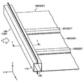
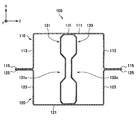
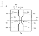
- FIG. 1 is a perspective view showing an example of a structural member 100 according to this embodiment and its peripheral structure.
- the structural member 100 has a closed cross section when viewed in cross section (XZ plan view) with the Y direction in FIG. 1 as the axial direction and the axial direction as the normal direction. Is.
- the structural member 100 is configured to include a first member 110 and a second member 120.
- a reinforcing portion (not shown; corresponding to a first wall 131 and a second wall 133 described later with reference to FIG. 2) is provided inside the closed cross section 101 of the structural member 100.
- the structural member 100 may receive a load F from the outside.
- the structural member 100 is arranged so that the first member 110 receives the load F.
- the reinforcing portion is provided in order to suppress the deformation of the structural member 100 due to the load F and improve the impact absorption characteristics. Details of the reinforcing portion will be described later.
- the structural member 100 may be configured as a part of the vehicle body structure 200.
- the vehicle body structure 200 includes a structural member 100, a first cross member 201, and a second cross member 203. Further, the vehicle body structure 200 may include the plate member 205. It should be noted that a first surface 111 of the structural member 100, which will be described later, is arranged on the outer side of the vehicle in the vehicle body structure 200, and a second surface 121 is arranged on the inner side of the vehicle.
- the first cross member 201 has a surface substantially opposite to the axial direction of the structural member 100 on the surface opposite to the side on which the load F is input with respect to the structural member 100 (see FIG. 1).
- the second cross member 203 is attached in a direction parallel to the first cross member 201 on the surface opposite to the side on which the load F is input to the structural member 100.
- the second cross member 203 is attached at a position different from that of the first cross member 201 in the axial direction of the structural member 100.
- the reinforcing portion is provided at least between the first cross member 201 and the second cross member 203 in the axial direction of the structural member 100.
- the vehicle body structure 200 is preferably an automobile floor structure.
- the floor structure in the example of FIG. 1 has a side sill 100′ as a structural member, a first floor cross member 201′ as a first cross member, and a second floor cross member 203′ as a second cross member. And a floor 205′ as a plate-shaped member.
- a first surface 111 which will be described later, is an outer surface in the vehicle width direction (X direction in FIG. 1)
- a second surface 121 is an inner surface in the vehicle width direction. ..
- the structural member 100 may constitute an automobile skeleton as a cabin skeleton or a shock absorbing skeleton. Examples of applications as a cabin skeleton include roof side rails, B pillars, A pillar lowers, and A pillar uppers, which are supposed to be bent by being supported by a cross member. In addition, the structural member 100 may be applied to a roof centering force, a tunnel, a kick clean force, an under lean force, a front header, or the like.
- the structural member 100 as a shock absorbing skeleton is a bumper reinforcement, which is supported by a cross member and in which bending input is assumed.
- the structural member 100 may be applied to a rear side member, an apron upper member, a bumper reinforcement, a crash box, a front side member, or the like.
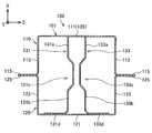
- FIG. 2 is a sectional view taken along the line II′ in FIG. 1, showing an example of the sectional structure of the structural member 100 according to the present embodiment.
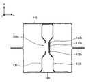
- the structural member 100 includes a first member 110, a second member 120, a first wall 131, and a second wall 133.
- the first member 110 and the second member 120 form a closed cross section 101 in the cross section in the XZ plane.
- the structural member 100 includes a first wall 131 and a second wall 133 inside the closed cross section 101.
- the first member 110 is a hat-shaped member in a sectional view of the XZ plane. More specifically, the first member 110 is adjacent to the top plate portion 111 as the first surface of the closed cross-section portion 101 and the end portion of the top plate portion 111 in the lateral direction (Z direction) with a bent portion interposed therebetween. And a flange portion 115 that is adjacent to the vertical wall portion 113 on the side opposite to the top plate portion 111 with another bent portion interposed therebetween.
- the first member 110 is manufactured by, for example, pressing a steel plate.
- the load F can be input to the top plate portion 111 from outside the structural member 100.
- the first member 110 is first deformed by the input of the load F.
- the vertical wall portion 113 deforms out of the plane together with the top plate portion 111. In this way, the vertical wall portion 113 improves the deformability of the first member 110 when the load F is input.
- the second member 120 is a hat-shaped member in a sectional view of the XZ plane. More specifically, the second member 120 is adjacent to the top plate portion 121 as the second surface of the closed cross-section portion 101 and the end portion of the top plate portion 121 in the lateral direction (Z direction) with a bent portion interposed therebetween. And a flange portion 125 that is adjacent to the vertical wall portion 123 on the opposite side of the top plate portion 121 with another bent portion interposed therebetween.
- the second member 120 is manufactured, for example, by pressing a steel plate.
- the structural member 100 Since the first member 110 and the second member 120 are joined to each other at their respective flange portions 115 and 125, the structural member 100 has a closed cross-section structure.
- a known joining technique such as laser welding or spot welding is used as the joining method, and the joining method is not particularly limited.
- the materials of the first member 110 and the second member 120 are, for example, steel materials having a tensile strength of 980 MPa class. Other materials may be, for example, steel materials of other tensile strength classes, light metal alloys such as aluminum-based alloys and magnesium-based alloys, and fiber reinforced resins such as CFRP (Carbon Fiber Reinforced Plastic). Good. Further, the first member 110 and the second member 120 may be configured by combining the above materials.
- the plate thickness of the first member 110 and the second member 120 is, for example, 1.6 mm, but is not particularly limited. The materials and plate thicknesses of the first member 110 and the second member 120 can be appropriately selected according to the purpose of use, the application, etc. of the structural member 100.
- the first wall 131 and the second wall 133 are the top plate portion 111 of the first member 110 and the top plate of the second member 120 inside the closed cross-section portion 101 of the structural member 100. It is provided between the parts 121.
- the first wall 131 extends from the top plate portion 121 of the second member 120 toward the top plate portion 111 of the first member 110.
- the second wall 133 extends from the top plate portion 121 of the second member 120 toward the top plate portion 111 of the first member 110.
- the first wall 131 and the second wall 133 extend in the axial direction (Y direction in FIG. 1) of the structural member 100. From the viewpoint of improving the shock absorption characteristics, the first wall 131 and the second wall 133 may be provided in at least a part of the axial direction (Y direction in FIG. 1) of the structural member 100.
- the structural member 100 has a space between the end of the first wall 131 on the side of the top plate 111 of the first member 110 and the end of the second wall 133 on the side of the top plate 111 of the first member 110. It has the connection part 135 which connects. That is, in the XZ plane cross-sectional view, the pair of the first wall 131 and the second wall 133 are connected by the connecting portion 135 at their Z-direction end portions.
- the first wall 131 has a first portion 131a, a second portion 131b, and a first groove portion 131c protruding toward the second wall 133 more than the first portion 131a and the second portion 131b.
- Have The first groove portion 131c extends in the axial direction (Y direction) of the structural member 100.
- the first wall 131 may have a first flange 131d that is bent from the end of the second portion 131b to the side opposite to the second wall 133 as shown in FIG.
- the second wall 133 has a first portion 133a, a second portion 133b, and a second groove portion 133c protruding toward the first wall 131 more than the first portion 133a and the second portion 133b.
- the second groove portion 133c extends in the axial direction (Y direction) of the structural member 100.
- the second wall 133 may have a second flange 133d that is bent from the end of the second portion 133b to the side opposite to the first wall 131.
- the distance between the first wall 131 and the second wall 133 is, for example, about 1/4 of the distance in the lateral direction (Z direction) of the top plate portion 111 of the first member 110.
- the first portion 131a of the first wall 131 is a flat plate-shaped portion on the top plate 111 side of the first member 110.
- the first portion 133 a of the second wall 133 is a flat plate-shaped portion on the top plate 111 side of the first member 110.
- the second portion 131b of the first wall 131 is a flat plate-shaped portion on the top plate 121 side of the second member 120.
- the second portion 133b of the second wall 133 is a flat plate-shaped portion on the top plate 121 side of the second member 120.
- the first groove 131c is provided between the first portion 131a and the second portion 131b of the first wall 131.
- the second groove 133c is provided between the first portion 133a and the second portion 133b of the second wall 133.
- the first groove portion 131c and the second groove portion 133c are preferably provided substantially at the centers of the first wall 131 and the second wall 133 in the X direction in FIG. In other words, it is preferable that the first groove portion 131c and the second groove portion 133c are provided at positions crossing the intermediate surface 101a.
- the intermediate surface 101a is a surface located between the first surface (top plate portion 111 in this embodiment) and the second surface (top plate portion 121 in this embodiment) of the closed cross section 101. More specifically, the intermediate surface 101a is a surface at a position of D/2, where D is the distance between the first surface and the second surface in the direction perpendicular to the first surface.
- first groove portion 131c and the second groove portion 133c are provided so as to cross the intermediate surface 101a, the first wall 131 and the second wall 131 and the second wall 133c start from the first groove 131c and the second wall 133c.
- the deformable portions of the first wall 131 and the second wall 133 on the top plate portion 111 side are left, and the first wall 131 and the second wall 133 on the top plate portion 121 side.
- the portion it is possible to suppress the back penetration amount.
- the details of the deformation of the first wall 131 and the second wall 133 will be described later.
- the depth of the first groove 131c (distance in the Z direction from the first portion 131a of the first wall 131) is preferably at least 6 mm.
- the depth of the second groove portion 133c (distance in the Z direction from the first portion 133a of the second wall 133) is preferably at least 6 mm.
- the width (distance in the X direction) of the first groove portion 131c is preferably 1 ⁇ 4 to 1 ⁇ 3 of the distance in the X direction of the first wall 131.
- the width (distance in the X direction) of the second groove 133c is preferably 1 ⁇ 4 to 1 ⁇ 3 of the distance in the X direction of the second wall 133.
- the shapes of the first groove portion 131c and the second groove portion 133c are not limited to the shapes shown in FIG.
- the first groove portion 131c and the second groove portion 133c come into contact with each other as the deformation of the first wall 131 and the second wall 133 starts. Any shape will do.
- first wall 131 and the second wall 133 are provided inside the closed cross section 101 as in the present embodiment, the first wall 131 and the second wall 133 are provided via the connecting portion 135 immediately after the deformation of the structural member 100 starts. The deformation of the wall 131 and the second wall 133 is also started. Therefore, the effect of improving the withstand load and the impact absorption characteristics by the first wall 131 and the second wall 133 is exhibited from the initial stage of deformation.
- the connecting portion 135 may be in contact with the top plate portion 111 of the first member 110 as shown in FIG.
- the connecting portion 135 may be joined to the inside of the closed cross-section portion 101 of the structural member 100 by welding or the like.
- the first wall 131 and the second wall 133 may be in direct contact with or joined to the top plate portion 111 of the first member 110 as shown in FIG.
- the connecting portion 135 is the top plate portion 111 of the first member 110.
- the connecting portion 135 may be a surface parallel to the top plate portion 111, which is not in contact with the top plate portion 111 of the first member 110 as shown in FIG. 4. Even in the case of FIG. 3 and FIG. 4, the first wall 131 and the second wall 133 are deformed via the connecting portion 135 when the load is input to the top plate portion 111. The shock absorption characteristics are improved as compared with the case where the 131 and the second wall 133 are not provided.
- the first wall 131 may have a first flange 131d that is continuous with the end opposite to the end connected to the connecting portion 135.
- the second wall 133 may have a second flange 133d continuous to the end opposite to the end connected to the connecting portion 135.
- the first wall 131 and the second wall 133 are welded to the inside of the top plate portion 121 of the second member 120 by welding or the like via the first flange 131d and the second flange 133d. It is installed.
- first wall 131 and the second wall 133 are joined to the inside of the closed cross-section portion 101 of the structural member 100 via the first flange 131d and the second flange 133d, the first wall 131 and the second wall 133 are connected to each other when the load is input.
- the wall 131 and the second wall 133 can be stably deformed.
- first wall 131 and the second wall 133 do not have the first flange 131d and the second flange 133d, and the end portions of the first wall 131 and the second wall 133 are second members. They may be joined by welding or the like in a state of directly abutting against the inside of the closed cross-section 101 of 120.
- the materials of the first wall 131 and the second wall 133 can be appropriately changed according to the shock absorption characteristics and the deformation characteristics, and are not particularly limited.
- it may be a steel material having a tensile strength of 980 MPa class, a steel material of other tensile strength class, a light metal alloy such as an aluminum base alloy or a magnesium base alloy, or a fiber reinforced resin such as CFRP.
- the materials of the first wall 131 and the second wall 133 may be the same as those of the first member 110 or the second member 120, or may be different materials.
- the plate thicknesses of the first wall 131 and the second wall 133 can be appropriately changed according to the impact absorption characteristics and the deformation characteristics, and are not particularly limited.
- the plate thickness of the first wall 131 and the second wall 133 is about 1.6 mm.
- the plate thickness of the first wall 131 and the second wall 133 may be the same as or different from the plate thickness of the first member 110 or the second member 120.
- the configuration example of the structural member 100 according to the present embodiment has been described above.
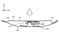
- FIG. 5A is a diagram schematically showing how the structural member 100 according to the present embodiment is deformed when a load is applied.
- FIG. 5B is a diagram schematically showing how the structural member 100 according to the present embodiment is deformed when a load is applied.
- the load F is input to the top plate portion 111 of the structural member 100.
- the vertical wall portion 113 of the first member 110 is out-of-plane deformed, and the first wall 131 and the second wall 133 are deformed.
- the first wall 131 and the second wall 133 receive the first load.
- the parts 131a, 133a and the connecting part 135 are deformed so as to bulge outward.
- the first groove portion 131c of the first wall 131 and the second groove portion 133c of the second wall 133 are deformed in a contacting direction. After that, the first wall 131 and the second wall 133 are deformed so as to be gradually crushed from the connecting portion 135 side.
- the first groove portion 131c and the second groove portion 133c are in contact with each other, the first member 131 side of the first wall 131 and the second wall 133 (the first portion 131a, 133a, the connecting portion).
- the deformation in the part 135) mainly proceeds. That is, when the first groove portion 131c and the second groove portion 133c contact each other, the first portions 131a and 133a are supported in the X direction in FIG. 5A with respect to the input load, and only that portion is selectively deformed. Can be made.
- the deformation on the first member 110 side progresses, while the large deformation does not occur on the second member 120 side.
- the deformation of the structural member 100 can be advanced only at the specific portion on the first member 110 side while improving the shock absorbing characteristics of the structural member 100.
- the first member 110 is largely deformed, and especially the vertical wall portion 113 is significantly out-of-plane deformed.
- the second member 120 is also largely deformed, but the deformation is suppressed to some extent as compared with the first member 110.
- the first member 110 side of the first wall 131 and the second wall 133 is almost crushed, and the second member 120 side of the first wall 131 and the second wall 133 is also partially deformed.
- the first wall 131 and the second wall 133 are deformed so as to fall in the Z direction in FIG. 5B as a whole (see the arrow in the figure). This is considered to be an influence of the bending moment due to the load F generated on the first wall 131 and the second wall 133.
- the manner of deformation of the structural member 100 according to the present embodiment has been described.
- the Li-ion battery module mounted on electric vehicles, hybrid vehicles, etc. which have become popular in recent years, may be arranged in the floor structure of the vehicle.
- the structural member side sill or the like
- the structural member may enter the inside of the structure. Therefore, in order to further improve the safety of the battery module, it is required to suppress the intrusion amount (back surface intrusion amount) of the structural member.
- the first member 110 side can be deformed and the second member 120 side can be suppressed from being deformed, so that the back penetration amount can be suppressed. ..
- the vehicle body structure 200 according to the present embodiment is a floor structure, it is possible to suppress the amount of rear surface penetration into the structure. As a result, components such as the Li-ion battery module arranged in the floor structure can be protected and safety can be further improved.
- FIG. 6 is a sectional view showing a modification of the structural member 100 according to the present embodiment.
- the first flange 131d and the second flange 133d are provided at the ends of the first wall 131 and the second wall 133 on the top plate 121 side, but as shown in FIG.
- the first flange 131d and the second flange 133d do not have to be provided.
- the shapes of the first wall 131 and the second wall 133 are symmetrical between the first member 110 side and the second member 120 side in the XZ plane sectional view in FIG. Has become.
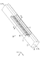
- FIG. 7 is a perspective view showing an example of the structural member 100 according to the second embodiment and its peripheral structure.
- FIG. 8 is an end view taken along the line II-II′ in FIG. 7, showing an example of the cross-sectional structure of the first groove portion 131c and the second groove portion 133c of the structural member 100 according to the present embodiment.
- FIG. 9 is an end view of III-III′ in FIG. 7, showing an example of a cross-sectional structure of the structural member 100 according to the present embodiment.
- the structural member 100 of the present embodiment has the reinforcing member 140.
- the deformation of the first wall 131 and the second wall 133 until the first groove portion 131c and the second groove portion 133c are in contact with each other is suppressed, and thus the above-described first member.
- the description of the configuration common to the first embodiment may be omitted.
- the structural member 100 has a reinforcing member between the first groove portion 131c of the first wall 131 and the second groove portion 133c of the second wall 133. It is equipped with 140.
- the reinforcing member 140 includes a plurality of wall portions 141 arranged between the first groove portion 131c of the first wall 131 and the second groove portion 133c of the second wall 133.
- the wall portion 141 extends such that the contact direction (Z direction in FIG. 8) between the first groove portion 131c and the second groove portion 133c substantially matches the in-plane direction of the wall portion 141 or has a predetermined angle. Is present. That is, the wall portion 141 is arranged so as to bridge between the first groove portion 131c of the first wall 131 and the second groove portion 133c of the second wall 133. Thereby, the load resistance of the first wall 131 and the second wall 133 when the first groove portion 131c and the second groove portion 133c are deformed so as to be in contact with each other can be improved.
- the reinforcing member 140 of this embodiment includes a first flat surface portion 143a, a second flat surface portion 143b, a first joint portion 145a, and a second joint portion 145b.
- the first joint portion 145a the first plane portion 143a and the first groove portion 131c of the first wall 131 are joined, and in the second joint portion 145b, the second plane portion 143b and the second wall 133.
- the second groove portion 133c is joined.
- first flat surface portion 143a and the second flat surface portion 143b may not be provided, and in that case, the first surface of the reinforcing member 140 and the first groove portion 131c are bonded at the first bonding portion 145a.
- second joint portion 145b it is preferable that the second surface of the reinforcing member 140 opposite to the first surface and the second groove portion 133c are joined.
- the first flat surface portion 143a may be attached to the first groove portion 131c by welding, and the second flat surface portion 143b may be attached to the second groove portion 133c by welding.
- the first groove portion 131c and the second groove portion 133c facing the welding point may be provided with the first hole portion 139a and the second hole portion 139b at positions corresponding to the welding point.
- the reinforcing member 140 includes a first groove portion 139a facing the second flat surface portion 143b, a first hole portion 139a, and a second groove portion facing the first flat surface portion 143a, as shown in FIG.
- the second hole 139b may be provided in 133c.
- the first hole portion 139a and the second hole portion 139b have an opening area that allows a welding tool (for example, a welding gun for spot welding) to pass through.
- a welding tool for example, a welding gun for spot welding
- the first hole 139a and the second hole 139b improve workability in spot welding, and the reinforcing member 140 is easily attached to the first wall 131 and the second wall 133.
- the reinforcing member 140 may have a wave shape when viewed in the X direction in FIG. That is, the reinforcing member 140 has a wave shape having an amplitude along a direction (Z direction in FIG. 8) in which the first groove portion 131c of the first wall 131 and the second groove portion 133c of the second wall 133 face each other. May have. Thereby, the number of the wall portions 141, the first flat surface portions 143a, and the second flat surface portions 143b can be increased, and the reinforcing member 140 can efficiently connect the first groove portions 131c and the second groove portions 133c to each other. It can be done in a targeted and robust manner.
- the welding points W of the reinforcing member 140 may be formed at intervals corresponding to half the predetermined wavelength L of the reinforcing member 140. That is, the reinforcing member 140 alternates between the first groove portion 131 c of the first wall 131 and the second groove portion 133 c of the second wall 133 at every L/2, which is the half-wavelength position where the amplitude is maximum. It is welded.
- first hole portion 139a is provided in the first groove portion 131c so as to correspond to the distance between the second joint portions 145b.
- second hole portion 139b is provided in the second groove portion 133c so as to correspond to the interval between the first joint portions 145a. That is, the first hole portion 139a and the second hole portion 139b have the first groove portion 131c of the first wall 131 and the first groove portion 131c for each half wavelength position where the amplitude of the reinforcing member 140 is the maximum half wavelength position.
- the second groove 133c of the second wall 133 is provided alternately.
- FIG. 10 is a diagram schematically showing how the structural member 100 according to the present embodiment is deformed when a load is applied.
- the first member 110 is largely deformed, and especially the vertical wall portion 113 is significantly out of plane. It is deformed.
- the second member 120 is also largely deformed, but the deformation is suppressed to some extent as compared with the first member 110. Further, the first member 110 side of the first wall 131 and the second wall 133 is almost crushed, and the second member 120 side of the first wall 131 and the second wall 133 is also partially deformed. ing.
- the first wall 131 and the second wall 133 are deformed such that the first wall 131 and the second wall 133 as shown in FIG. 5B fall as a whole in the Z direction. Not shown.
- the first hole portions 139a are provided at constant positions at positions corresponding to the second joint portions 145b, and the second hole portions 139b are constant distance at positions corresponding to the first joint portions 145a. Because it is provided in. That is, since the first hole 139a and the second hole 139b are evenly provided, the influence of the bending moment generated on the first wall 131 and the second wall 133 by the load F is It is considered that the wall 131 and the second wall 133 cancel each other.
- the bending moment generated in the first wall 131 by the load F and the bending moment generated in the second wall 133 are opposite to each other and work to cancel each other out.
- the first wall 131 and the second wall 133 are suppressed from being deformed in the Z direction in FIG. 9, and the deformation is stabilized.
- the reinforcing member 140 suppresses the deformation of the first wall 131 and the second wall 133 until the first groove portion 131c and the second groove portion 133c contact each other.
- the deformation of the first wall 131 and the second wall 133 is partially suppressed, and the withstand load is improved, while the deformation of the first member 110 side proceeds and the deformability is improved.
- the impact absorption characteristics of the structural member 100 are improved.
- the structural member 100 according to the second embodiment has been described above.
- the shape of the reinforcing member 140 is not particularly limited as long as the deformation of the first groove portion 131c and the second groove portion 133c until the first groove portion 131c and the second groove portion 133c contact each other can be suppressed.
- the reinforcing member 140 is a hollow or solid rod-shaped, plate-shaped, or hollow or solid box-shaped member, and is disposed between the first groove portion 131c and the second groove portion 133c in the axial direction of the structural member 100. It may be provided along (Y direction in FIG. 6).
- the reinforcing member 140 is disposed between the first groove portion 131c and the second groove portion 133c and is joined to the first groove portion 131c or the second groove portion 133c, the second embodiment will be described. As described above, the shock absorption characteristics can be improved.
- the material of the reinforcing member 140 may be steel, light metal, fiber reinforced resin, soft or hard resin, or the like.
- the wave shape of the reinforcing member 140 is not limited to the rectangular wave shape.
- the wave shape of the reinforcing member 140 can take a wave shape having various wavelengths, phases, or amplitudes, depending on the deformation characteristics.
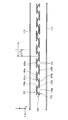
- FIG. 11 is a figure which shows an example of the cross-section of the axial direction of the structural member which concerns on 3rd Embodiment.
- FIG. 12 is an end view taken along the line IV-IV′ in FIG. 11, showing an example of the sectional structure of the structural member according to the embodiment.
- the structural member 100 of this embodiment includes a first wall 131, a second wall 133, and two third walls 150.
- the third wall 150 extends in the axial direction (Y direction) of the structural member 100.
- the third wall 150 of this embodiment has a plate shape.
- the end portion 150a is joined to the first groove portion 131c so as to be connected to each other, and the end portion 150b is connected to the second end portion 150b. They are connected to each other by being joined to the groove portion 133c.
- the method of joining the third wall 150 to the first groove portion 131c and the second groove portion 133c is not particularly limited.
- the third wall 150 is provided, until the first groove portion 131c and the second groove portion 133c come into contact with each other as in the structural member 100 of the second embodiment.
- the deformation of the first wall 131 and the second wall 133 is suppressed. Thereby, the deformation of the first wall 131 and the second wall 133 is partially suppressed, the withstand load can be improved, and the shock absorption characteristics are improved.
- the structural member 100 preferably includes a plurality of third walls 150 as shown in FIG.
- a load is input to the structural member 100, for example, a bending moment with the end 150a of the third wall 150 as the center of rotation is generated, and The effect of suppressing the deformation until the groove 131c and the second groove 133c contact each other is small.
- the deformation due to the bending moment as described above that occurs in one third wall 150 can be suppressed in the other third wall 150.
- the deformation strength of the first wall 131 and the second wall 133 until the first groove portion 131c and the second groove portion 133c contact each other is increased, and the load resistance is improved.
- the third wall 150 of the present embodiment is inclined with respect to the first surface of the structural member 100, but may be parallel to the first surface. Further, although the shape of the third wall 150 of the present embodiment is a plate shape, the shape of the third wall 150 is not particularly limited.
- the material of the third wall 150 may be steel, light metal, fiber reinforced resin, soft or hard resin, or the like.
- Comparative Example 1 is a structural member including only the first member 110 and the second member 120. Further, Comparative Example 2 was a structural member having a first wall and a second wall having no groove. Example 1 is the structural member 100 according to the first embodiment described above.
- Both the first member and the second member of Comparative Example 1 were steel plates having a tensile strength of 980 MPa and a plate thickness of 1.8 mm.
- the first member and the second member of Comparative Example 2 were steel plates having a tensile strength of 980 MPa class and a plate thickness of 1.4 mm, and the reinforcing members were steel plates having a tensile strength of 980 MPa class and a plate thickness of 1.6 mm.
- the example is made of the same steel plate as that of the comparative example 2.
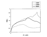
- FIGS. 13A and 13B are diagrams for explaining an example of conditions for simulation analysis. That is, as shown in FIG. 13A, the indenter P (pole) for three-point bending has a diameter ⁇ of 254 mm, and the pole is moved toward the load input surface 111 of the first member 110 of the structural member at a predetermined speed. (Refer to the arrow in the figure). The distance t between the two rigid body supporting points G1 and G2 on the second member 120 side of the structural member was 300 mm, and the pole was made to collide with the midpoint between the two rigid body supporting points G1 and G2. The load generated between the pole and the structural member and the back surface penetration amount ( ⁇ b) into the first member 110 at the center position of the pole were measured.
- ⁇ b back surface penetration amount
- the back surface penetration amount ⁇ b is an evaluation value of the penetration amount of the structural member on the side opposite to the load input surface. The smaller this value is, the more the penetration amount of the structural member on the side opposite to the load input surface is suppressed. Means being done. Specifically, as shown in FIG. 13B, the initial position in the load input direction of the top plate portion (the surface supported by the two rigid body support points) of the second member 120 before the pole collision, and the first position associated with the deformation. This is the difference from the position of the top plate portion of the second member 120 in the load input direction.
- FIG. 14A is a graph showing a relationship between a pole displacement of a structural member and a back penetration amount ratio in a three-point bending simulation.
- the back penetration amount ( ⁇ b) ratio is a value obtained by normalizing each measurement result by the maximum back penetration amount ⁇ b of Comparative Example 1.
- Comparative Example 2 having a reinforcing member having no recess has a back surface penetration amount ( ⁇ b) ratio of about twice, and a structural member on the side opposite to the load input surface. Has invaded a lot.
- Example 1 having the first wall 131 and the second wall 133 according to the present embodiment had a back surface penetration amount ( ⁇ b) ratio similar to that of Comparative Example 1.
- the structural member 100 according to the present embodiment suppresses the amount of intrusion into the side opposite to the load input surface 111. Furthermore, since the plate thickness of the structural member 100 of the example is 1.6 mm and the plate thickness of the comparative example 1 is 1.8 mm, the structural member 100 according to the present embodiment can realize weight reduction. Was also shown.
- FIG. 14B is a graph showing the relationship between the pole displacement and the load ratio of the structural member in the three-point bending simulation.
- the load ratio is obtained by normalizing the measurement result of the input load at the time of pole collision with the maximum value of the load of Comparative Example 1.
- the load ratio of Example 1 was higher than that of Comparative Example 1, and the withstand load was improved.
- Example 1 is comparable to Comparative Example 2 having a first wall and a second wall without grooves. From this, it was shown that the structural member 100 according to the present embodiment is deformed by a high load.
- the energy absorption amount EA is the integral value of the load with respect to the pole displacement.
- the energy absorption amount EA is divided by the mass of the structural member and further divided by the back surface penetration amount ⁇ b, and the value EA/mass/ ⁇ b is used as an evaluation value for comparison.
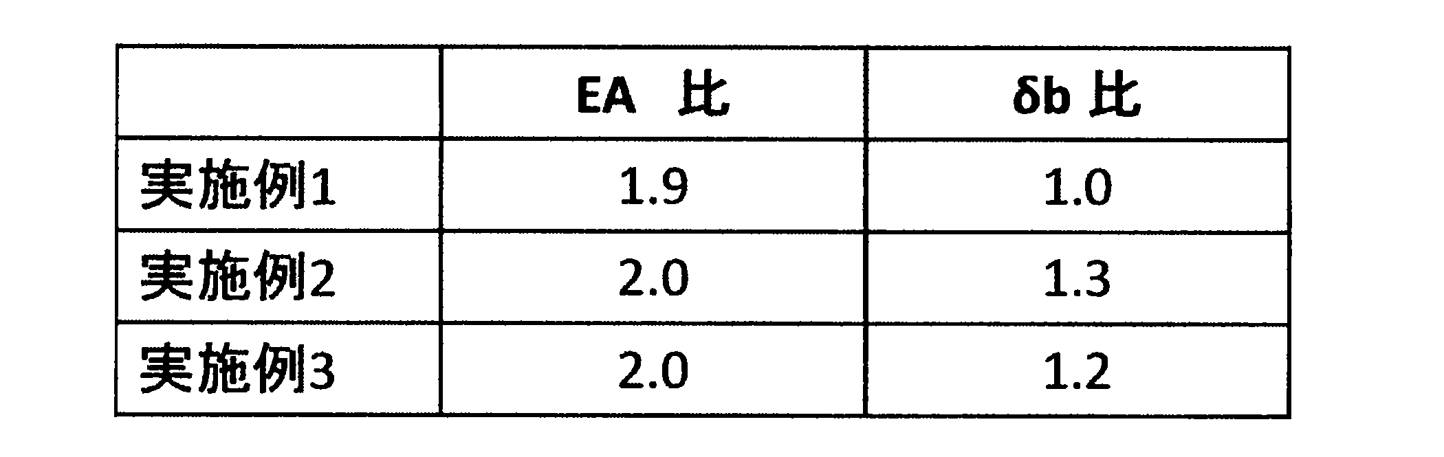
- the comparison results are shown in Table 1.
- the values in Table 1 are standardized with the values in Comparative Example 1.
- Example 1 As shown in Table 1, the value of EA/mass/ ⁇ b ratio in Example 1 was significantly higher than those in Comparative Examples 1 and 2. From this, it is shown that the structural member 100 according to the present embodiment achieves both mass efficiency with high impact absorption performance and suppression of the back surface penetration amount ⁇ b.
- Example 2 is the structural member 100 including the reinforcing member 140.
- the third embodiment is the structural member 100 that includes the reinforcing member 140 and further includes the first hole portion 139a and the second hole portion 139b at positions corresponding to the welding points.
- Table 2 shows the results of comparison of Examples 1 to 3 with respect to the energy absorption amount (EA) ratio and the back surface penetration amount ( ⁇ b) ratio. The measurement results of both the EA ratio and the ⁇ b ratio are standardized with the values of Comparative Example 1.
- EA energy absorption amount
- ⁇ b back surface penetration amount
- Example 2 and Example 3 had a higher energy absorption (EA) ratio than Example 1. From this, it was shown that the reinforcing member 140 enhances the shock absorbing performance of the structural member 100. Further, comparing Example 2 with Example 3, the back surface penetration amount ( ⁇ b) ratio of Example 3 was reduced as compared with Example 2. This is because, as a result of the first holes 139a and the second holes 139b being evenly arranged, the bending moment that deforms the first wall 131 and the second wall 133 so as to fall is suppressed, and the shock absorbing effect. It is thought that this is due to the improvement of Thus, it was shown that the back surface penetration amount is further suppressed by the structural member 100 including the first hole portion 139a and the second hole portion 139b.
- the first member 110 has a hat shape, but the first member 110 is not limited to such an example.
- the first member 110 has only to have a shape for forming the structural member 100, and may have a U-shape, an arc shape, or the like in a cross-sectional view. Further, the first member 110 may be partially bent in a cross-sectional view, or may have irregularities such as a bead shape.
- the second member 120 has a hat shape, but the second member 120 is not limited to such an example.
- the second member 120 may be a plate-shaped member. That is, the so-called one-hat shaped structural member 100 in which the first member has a substantially hat shape in cross section and the second member is a closing plate may be used.
- the second member 120 may be partially bent in a sectional view, or may have irregularities such as a bead shape.
- first member 110 and the second member 120 are welded via the flange portions 115 and 125, but the welding positions of the first member 110 and the second member 120 are It is not limited to such an example.
- first member 110 and the second member 120 may be welded to each other near the ends of the vertical wall portions 113 and 123 having a substantially hat shape.
- a member forming the outer shape of the structural member 100 may be included. Further, another member may be provided between the first member 110 and the second member 120. Moreover, the first member 110 and the second member 120 may be covered from the outside by the cover member.
- the closed cross section 101 of the structural member 100 is composed of the first member 110 and the second member 120, but the closed cross section 101 is, for example, a hollow rectangular tube as shown in FIG. It may be composed of the member 105.
- the first wall 131 and the second wall 133 are connected to the first surface 111 and the second surface 121 of the structural member 100.
- the connecting portion 135 that connects the first wall 131 and the second wall 133 is the first surface 111.
- Such a structural member 100 is manufactured by, for example, extrusion molding.
- the material of the hollow member 105 is, for example, a steel material having a tensile strength of 980 MPa class. Further, other materials may be, for example, steel materials of other tensile strength classes, light metal alloys such as aluminum-based alloys and magnesium-based alloys, and fiber reinforced resins such as CFRP.
- the structural member 100 may have the structure shown in FIG. 16 or FIG. 17, for example.
- the first wall 131 and the second wall 133 are not connected to the first surface 111, and the first wall 131 and the second wall 133 have the closed cross section 101.
- the first surface 111 and the first surface 111 are connected to each other via a connecting portion 135 which is a surface parallel to the first surface 111.
- the structural member 100 in the example of FIG. 17 includes a first wall 131, a second wall 133, and a plurality of third walls 150, similar to the structure shown in FIG.
- the structure in the closed cross section 101 may be the same as that of the first to third embodiments.
- Structural Member 101 Closed Cross Section 101a Intermediate Surface 105 Hollow Member 110 First Member 111 Top Plate (First Surface of Closed Cross Section) 120 Second member 121 Top plate portion (second surface of closed cross-section portion) 131 1st wall 133 2nd wall 131c 1st groove part 133c 2nd groove part 131d 1st flange 133d 2nd flange 135 Connection part 139a 1st hole 139b 2nd hole 140 Reinforcement member 141 Wall Part 143a First flat part 143b Second flat part 145a First joining part 145b Second joining part 150 Third wall
Landscapes
- Engineering & Computer Science (AREA)
- General Engineering & Computer Science (AREA)
- Mechanical Engineering (AREA)
- Chemical & Material Sciences (AREA)
- Combustion & Propulsion (AREA)
- Transportation (AREA)
- Body Structure For Vehicles (AREA)
- Vibration Dampers (AREA)
Abstract
閉断面部と閉断面部の内部に第1の壁と第2の壁を備え、閉断面部は、第1の面と第2の面を備え、第1の面と第2の面は、対向し、第1の壁と第2の壁は、第2の面から第1の面に向かって延在し、第1の壁と第2の壁は、閉断面部の軸方向に延在し、第1の壁は、第2の壁に向かって突出した、軸方向に延在する第1の溝部を備え、第2の壁は、第1の壁に向かって突出した、軸方向に延在する第2の溝部を備え、第1の壁の第1の面側の端部と第2の壁の第1の面側の端部は、連結部を介して繋がっている、構造部材。
Description
本開示は、構造部材及び車体構造に関する。
従来の構造部材及び車体構造においては、安全性の向上のため、衝突時の衝撃吸収特性をさらに向上させることが求められる。特に、自動車の側面衝突時には、サイドシル等の車両側部に配置された構造部材が、塑性変形し、衝撃を吸収する。
下記特許文献1にはサイドシルの閉断面内に補強部材、ガイド棒およびダンパーといった複数の機構または部材を組み合わせて配置し、衝撃吸収性能を高める技術が開示されている。
しかし、上記特許文献1に記載の技術では、複数の機構または部材を組み合わせた結果、構造が複雑になり、重量も増大するという問題があった。また、上記特許文献1の技術では、衝撃吸収特性の中でも塑性変形時の構造部材の車体内部への侵入量を抑制することについては考慮されていなかった。
そこで、本開示は、上記問題に鑑みてなされたものであり、本開示の目的とするところは、複雑な機構部材を必要とせず、高い質量効率を実現しながら、構造部材における要求特性の一つである衝撃吸収性能をさらに向上させることが可能な、新規かつ改良された構造部材および車体構造を提供することにある。
上記課題を解決するために、本開示のある観点によれば、閉断面部と前記閉断面部の内部に第1の壁と第2の壁を備え、前記閉断面部は第1の面と第2の面を備え、前記第1の面と前記第2の面は対向し、前記第1の壁と前記第2の壁は前記第2の面から前記第1の面に向かって延在し、前記第1の壁と前記第2の壁は前記閉断面部の軸方向に延在し、前記第1の壁は前記第2の壁に向かって突出した前記軸方向に延在する第1の溝部を備え、前記第2の壁は前記第1の壁に向かって突出した前記軸方向に延在する第2の溝部を備え、前記第1の壁の前記第1の面側の端部と前記第2の壁の前記第1の面側の端部は連結部を介して繋がっている、構造部材が提供される。
また、上記課題を解決するために、本開示の別の観点によれば、上記の構造部材を備え、前記第1の面が車外側に配置され、前記第2の面が車内側に配置されている、車体構造が提供される。
以上説明したように本開示によれば、衝撃吸収性能をさらに向上させることが可能な、新規かつ改良された構造部材および車体構造が提供される。
以下に添付図面を参照しながら、本開示の好適な実施の形態について詳細に説明する。なお、本明細書及び図面において、実質的に同一の機能構成を有する構成要素については、同一の符号を付することにより重複説明を省略する。
<1.第1の実施形態>
[車体構造の構成例]
まず、図1を参照して、第1の実施形態に係る構造部材100の概略構成について説明する。図1は、本実施形態に係る構造部材100とその周辺構造の一例を示す斜視図である。図1に示すように、構造部材100は、図1におけるY方向を軸方向とし、軸方向を法線方向とする断面視(X-Z平面視)したときに、閉断面となっている部材である。構造部材100は、第1の部材110と、第2の部材120とを含んで構成されている。構造部材100の閉断面部101の内部には、補強部(図示せず。図2で後述する第1の壁131と第2の壁133に相当)が設けられている。
[車体構造の構成例]
まず、図1を参照して、第1の実施形態に係る構造部材100の概略構成について説明する。図1は、本実施形態に係る構造部材100とその周辺構造の一例を示す斜視図である。図1に示すように、構造部材100は、図1におけるY方向を軸方向とし、軸方向を法線方向とする断面視(X-Z平面視)したときに、閉断面となっている部材である。構造部材100は、第1の部材110と、第2の部材120とを含んで構成されている。構造部材100の閉断面部101の内部には、補強部(図示せず。図2で後述する第1の壁131と第2の壁133に相当)が設けられている。
図1に示すように、構造部材100は、外部から荷重Fを受ける場合がある。構造部材100は、第1の部材110が当該荷重Fを受けるように配置される。補強部は、当該荷重Fによる構造部材100の変形を抑制しつつ、衝撃吸収特性を向上させるために、設けられる。補強部についての詳細は後述する。
また、図1に示すように、構造部材100は、車体構造200の一部として構成されてもよい。車体構造200は、構造部材100と、第1のクロス部材201と、第2のクロス部材203とを有する。また、車体構造200は、板状部材205を有してもよい。なお、後述する構造部材100の第1の面111は、車体構造200における車外側と車内側のうち車外側に配置され、第2の面121は車内側に配置される。
図1に示すように、第1のクロス部材201は、構造部材100に対して荷重Fが入力される側とは反対側の面において、構造部材100の軸方向と略直交する方向(図1におけるX方向)に取り付けられている。また、第2のクロス部材203は、構造部材100へ荷重Fが入力される側とは反対側の面において、第1のクロス部材201と平行な方向に取り付けられている。さらに、第2のクロス部材203は、構造部材100の軸方向において、第1のクロス部材201とは異なる位置に取り付けられている。補強部は、構造部材100の軸方向において、少なくとも第1のクロス部材201と第2のクロス部材203との間に設けられている。
車体構造200は、自動車のフロア構造であることが好ましい。図1の例におけるフロア構造は、構造部材としてのサイドシル100’と、第1のクロス部材としての第1のフロアクロスメンバ201’と、第2のクロス部材としての第2のフロアクロスメンバ203’と、板状部材としてのフロア205’とを有する。構造部材がサイドシルである場合、後述の第1の面111は車幅方向(図1におけるX方向)の車外側の面であり、第2の面121は車幅方向の車内側の面である。
構造部材100は、キャビン骨格または衝撃吸収骨格として自動車骨格を構成し得る。キャビン骨格としての適用例は、特にクロス部材により支持されて曲げ入力が想定される、ルーフサイドレール、Bピラー、Aピラーロア、Aピラーアッパーが挙げられる。また、その他に、構造部材100は、ルーフセンタリンフォース、トンネル、キックリーンフォース、アンダーリーンフォース、フロントヘッダ等に適用されてもよい。
また、衝撃吸収骨格としての構造部材100の適用例は、特にクロス部材により支持されて曲げ入力が想定される、バンパリーンフォースが挙げられる。また、その他に、構造部材100は、リアサイドメンバー、エプロンアッパメンバ、バンパリーンフォース、クラッシュボックス、フロントサイドメンバー等に適用されてもよい。
[構造部材の構成例]
次に、図2を参照して、本実施形態に係る構造部材100の断面構造について説明する。図2は、本実施形態に係る構造部材100の断面構造の一例を示す、図1におけるI-I’断面図である。図2に示すように、構造部材100は、第1の部材110と、第2の部材120と、第1の壁131と、第2の壁133とを備えている。構造部材100は、第1の部材110と第2の部材120とにより、X-Z平面の断面において、閉断面部101が形成されている。構造部材100は、当該閉断面部101の内部に第1の壁131と第2の壁133を備えている。
次に、図2を参照して、本実施形態に係る構造部材100の断面構造について説明する。図2は、本実施形態に係る構造部材100の断面構造の一例を示す、図1におけるI-I’断面図である。図2に示すように、構造部材100は、第1の部材110と、第2の部材120と、第1の壁131と、第2の壁133とを備えている。構造部材100は、第1の部材110と第2の部材120とにより、X-Z平面の断面において、閉断面部101が形成されている。構造部材100は、当該閉断面部101の内部に第1の壁131と第2の壁133を備えている。
第1の部材110は、X-Z平面の断面視でハット形状の部材である。詳述すると、第1の部材110は、閉断面部101の第1の面としての天板部111と、天板部111の短手方向(Z方向)の端部に屈曲部を挟んで隣接する縦壁部113と、縦壁部113の天板部111と反対側において別の屈曲部を挟んで隣接するフランジ部115とを有する。第1の部材110は、例えば鋼板のプレス加工等により製造される。
天板部111には、構造部材100の外方から荷重Fが入力され得る。荷重Fの入力によって、まず第1の部材110が変形する。このとき、天板部111とともに縦壁部113が面外変形する。このように縦壁部113により、荷重Fが入力された際の、第1の部材110の変形能が向上される。
第2の部材120は、X-Z平面の断面視でハット形状の部材である。詳述すると、第2の部材120は、閉断面部101の第2の面としての天板部121と、天板部121の短手方向(Z方向)の端部に屈曲部を挟んで隣接する縦壁部123と、縦壁部123の天板部121と反対側において別の屈曲部を挟んで隣接するフランジ部125とを有する。第2の部材120は、例えば鋼板のプレス加工等により製造される。
第1の部材110と第2の部材120とが、それぞれのフランジ部115、125で互いに接合されるので、構造部材100が閉断面構造になる。接合方法は、レーザ溶接、スポット溶接などの公知の接合技術が用いられ、特に限定されない。
第1の部材110と、第2の部材120の材質は、例えば、引張強度で980MPa級の鋼材である。また、その他の材質として、例えば、その他の引張強度クラスの鋼材であってもよいし、アルミニウム基合金、マグネシウム基合金等の軽金属合金、CFRP(Carbon Fiber Reinforced Plastic)等の繊維強化樹脂であってもよい。また、第1の部材110と、第2の部材120とは、上記材料を組み合わせて、構成されてもよい。また、第1の部材110、および第2の部材120の板厚は、例えば、1.6mmであるが、特に限定されない。第1の部材110および第2の部材120の材質および板厚は、構造部材100の使用目的、用途等に応じて適宜選択され得る。
[第1の壁と第2の壁]
引き続き、図2を参照しながら、本実施形態に係る第1の壁131と第2の壁133について説明する。図2に示すように、第1の壁131と第2の壁133は、構造部材100の閉断面部101の内部において第1の部材110の天板部111と第2の部材120の天板部121の間に設けられている。第1の壁131は、第2の部材120の天板部121から第1の部材110の天板部111に向かって延在している。同様に、第2の壁133は、第2の部材120の天板部121から第1の部材110の天板部111に向かって延在している。これらの第1の壁131と第2の壁133は、構造部材100の軸方向(図1におけるY方向)に延在している。衝撃吸収特性を向上させる観点からは、第1の壁131と第2の壁133は、構造部材100の軸方向(図1におけるY方向)の少なくとも一部において、設けられていればよい。
引き続き、図2を参照しながら、本実施形態に係る第1の壁131と第2の壁133について説明する。図2に示すように、第1の壁131と第2の壁133は、構造部材100の閉断面部101の内部において第1の部材110の天板部111と第2の部材120の天板部121の間に設けられている。第1の壁131は、第2の部材120の天板部121から第1の部材110の天板部111に向かって延在している。同様に、第2の壁133は、第2の部材120の天板部121から第1の部材110の天板部111に向かって延在している。これらの第1の壁131と第2の壁133は、構造部材100の軸方向(図1におけるY方向)に延在している。衝撃吸収特性を向上させる観点からは、第1の壁131と第2の壁133は、構造部材100の軸方向(図1におけるY方向)の少なくとも一部において、設けられていればよい。
構造部材100は、第1の壁131の、第1の部材110の天板部111側端部と、第2の壁133の、第1の部材110の天板部111側端部の間を繋ぐ連結部135を有する。すなわち、X-Z平面断面視で、一対の第1の壁131と第2の壁133は、それぞれのZ方向端部で、連結部135により繋がっている。
第1の壁131は、第1の部位131aと、第2の部位131bと、第1の部位131aおよび第2の部位131bよりも第2の壁133に向かって突出した第1の溝部131cを有している。第1の溝部131cは、構造部材100の軸方向(Y方向)に延在している。また、第1の壁131は、図2のように第2の部位131bの端部から、第2の壁133と反対側へ屈曲された第1のフランジ131dを有してもよい。
第2の壁133は、第1の部位133aと、第2の部位133bと、第1の部位133aおよび第2の部位133bよりも第1の壁131に向かって突出した第2の溝部133cを有している。第2の溝部133cは、構造部材100の軸方向(Y方向)に延在している。また、第2の壁133は、第2の部位133bの端部から、第1の壁131と反対側へ屈曲された第2のフランジ133dを有してもよい。
第1の壁131と第2の壁133の間の距離は、例えば第1の部材110の天板部111の短手方向(Z方向)距離の1/4程度である。
第1の壁131の第1の部位131aは、第1の部材110の天板部111側にある平板状の部位である。第2の壁133の第1の部位133aは、第1の部材110の天板部111側にある平板状の部位である。また、第1の壁131の第2の部位131bは、第2の部材120の天板部121側にある平板状の部位である。第2の壁133の第2の部位133bは、第2の部材120の天板部121側にある平板状の部位である。
第1の溝部131cは、第1の壁131の、第1の部位131aと第2の部位131bの間に設けられている。第2の溝部133cは、第2の壁133の、第1の部位133aと第2の部位133bの間に設けられている。第1の溝部131cと第2の溝部133cは、図2におけるX方向で第1の壁131と第2の壁133の略中央に設けられていることが好ましい。換言すると、第1の溝部131cと第2の溝部133cは、中間面101aを横切る位置に設けられていることが好ましい。中間面101aとは、閉断面部101の第1の面(本実施形態では天板部111)と、第2の面(本実施形態では天板部121)の中間に位置する面である。より詳述すると、中間面101aは、第1の面に垂直な方向の第1の面と第2の面の間隔をDとしたときに、D/2の位置にある面である。
第1の溝部131cと第2の溝部133cが中間面101aを横切るように設けられていることで、第1の溝部131cと第2の溝部133cを起点として第1の壁131と第2の壁133が変形する際に、第1の壁131と第2の壁133の天板部111側の変形可能な部分を残しつつ、第1の壁131と第2の壁133の天板部121側の部分によって、背面侵入量を抑制することができる。なお、第1の壁131と第2の壁133の変形の詳細については後述する。
第1の溝部131cの深さ(第1の壁131の第1の部位131aからのZ方向距離)は、少なくとも6mmであることが好ましい。第2の溝部133cの深さ(第2の壁133の第1の部位133aからのZ方向距離)は、少なくとも6mmであることが好ましい。第1の溝部131cの幅(X方向距離)は、第1の壁131のX方向距離に対して、1/4~1/3であることが好ましい。第2の溝部133cの幅(X方向距離)は、第2の壁133のX方向距離に対して、1/4~1/3であることが好ましい。
また、第1の溝部131cと第2の溝部133cの形状は、図2に示したような形状に限定されない。例えば第1の部材110の天板部111への荷重入力後、第1の壁131と第2の壁133の変形開始に伴って、第1の溝部131cと第2の溝部133c同士が接触する形状であればよい。
本実施形態のように閉断面部101の内部に第1の壁131と第2の壁133が設けられていることにより、構造部材100の変形開始直後から、連結部135を介して第1の壁131と第2の壁133の変形も開始される。従って、第1の壁131と第2の壁133による耐荷重向上や衝撃吸収特性の向上効果が、変形開始初期から発揮される。
連結部135は、図2のように第1の部材110の天板部111に接触していてもよい。この場合、連結部135は、構造部材100の閉断面部101の内側に溶接等により接合されていてもよい。また、第1の壁131と第2の壁133は、図3のように第1の部材110の天板部111に直接接触または接合されていてもよい。この場合の連結部135とは、第1の部材110の天板部111である。また、連結部135は、図4のように第1の部材110の天板部111に当接していない、天板部111に平行な面であってもよい。図3および図4のような場合であっても、天板部111への荷重入力時には連結部135を介して第1の壁131と第2の壁133が変形することから、第1の壁131と第2の壁133が設けられていない場合に比べて衝撃吸収特性が向上する。
第1の壁131は、連結部135に繋がっている端部とは反対側の端部に連続する第1のフランジ131dを有していてもよい。第2の壁133は、連結部135に繋がっている端部とは反対側の端部に連続する第2のフランジ133dを有していてもよい。図2の例において、第1の壁131と第2の壁133は、第2の部材120の天板部121の内側に、第1のフランジ131dと第2のフランジ133dを介して溶接等により取り付けられている。第1の壁131と第2の壁133が第1のフランジ131dと第2のフランジ133dを介して構造部材100の閉断面部101の内側に接合されていることにより、荷重入力時に第1の壁131と第2の壁133が安定して変形できる。
なお、第1の壁131と第2の壁133は、第1のフランジ131dと第2のフランジ133dを介さずに、第1の壁131と第2の壁133の端部が第2の部材120の閉断面部101の内側に直接突き当てられた状態で、溶接等によって接合されていてもよい。
第1の壁131と第2の壁133の材質は、衝撃吸収特性、変形特性に応じて、適宜変更でき、特に限定されない。例えば、引張強度で980MPa級の鋼材や、その他の引張強度クラスの鋼材であってもよいし、アルミニウム基合金、マグネシウム基合金等の軽金属合金、CFRP等の繊維強化樹脂であってもよい。また、第1の壁131と第2の壁133の材質は、第1の部材110または第2の部材120と同一の材料であってもよいし、異なる材質であってもよい。
また、第1の壁131と第2の壁133の板厚についても、衝撃吸収特性、変形特性に応じて、適宜変更でき、特に限定されない。例えば、第1の壁131と第2の壁133の板厚は、1.6mm程度である。また、例えば、第1の壁131と第2の壁133の板厚は、第1の部材110または第2の部材120と同一または異なる板厚であってもよい。以上、本実施形態に係る構造部材100の構成例について説明した。
[構造部材の変形]
次に、図5A、図5Bを参照して、本実施形態に係る構造部材100に荷重がかかったときの変形の様子について説明する。図5Aは、本実施形態に係る構造部材100に荷重がかかったときの変形の様子を模式的に示す図である。図5Bは、本実施形態に係る構造部材100に荷重がかかったときの変形の様子を模式的に示す図である。図5Aに示すように、例えば荷重Fが、構造部材100の天板部111に対して入力される。このとき、第1の部材110の縦壁部113が面外変形するとともに、第1の壁131と第2の壁133が変形する。
次に、図5A、図5Bを参照して、本実施形態に係る構造部材100に荷重がかかったときの変形の様子について説明する。図5Aは、本実施形態に係る構造部材100に荷重がかかったときの変形の様子を模式的に示す図である。図5Bは、本実施形態に係る構造部材100に荷重がかかったときの変形の様子を模式的に示す図である。図5Aに示すように、例えば荷重Fが、構造部材100の天板部111に対して入力される。このとき、第1の部材110の縦壁部113が面外変形するとともに、第1の壁131と第2の壁133が変形する。
具体的には、第1の壁131と第2の壁133に第1の部材110の天板部111から荷重が伝達されると、第1の壁131と第2の壁133の第1の部位131a、133a、および連結部135が外方に膨らむようにして変形する。また、第1の壁131の第1の溝部131cと、第2の壁133の第2の溝部133c同士が接触する方向に変形する。その後、第1の壁131と第2の壁133は、連結部135側から次第に押し潰されるように変形する。このとき、第1の溝部131cと第2の溝部133c同士は接触しているので、第1の壁131と第2の壁133の第1の部材110側(第1の部位131a、133a、連結部135)での変形が主に進行する。すなわち、第1の溝部131cと第2の溝部133c同士が接触することにより、入力荷重に対して第1の部位131a、133aが図5AにおけるX方向に支持され、当該部位のみを選択的に変形させることができる。
この結果、図5Aに示すように、第1の部材110側の変形が進む一方で、第2の部材120側では、大きな変形が生じない。このように、構造部材100の衝撃吸収特性が向上しつつ、第1の部材110側という特定部位のみで変形を進行させることができる。
さらに、変形が進むと、図5Bに示すように、第1の部材110は、大きく変形し、特に縦壁部113が著しく面外変形している。一方、第2の部材120も大きく変形しているが、第1の部材110と比較すれば、変形はある程度抑制されている。また、第1の壁131と第2の壁133の第1の部材110側は、ほぼ圧潰し、第1の壁131と第2の壁133の第2の部材120側も部分的に変形している。さらに、第1の壁131と第2の壁133が全体として図5B中のZ方向へ倒れるように変形している(図中矢印参照)。これは、第1の壁131と第2の壁133に生じた荷重Fによる曲げモーメントとの影響と考えられる。以上、本実施形態に係る構造部材100の変形の様子について説明した。
(作用効果)
本実施形態によれば、構造部材100の第1の溝部131cと第2の溝部133c同士の接触により、第1の壁131と第2の壁133の変形が部分的に抑制され、耐荷重が向上するとともに、一方、第1の部材110側の変形が進行し、変形能が向上する。この結果、構造部材100の衝撃吸収特性が向上する。
本実施形態によれば、構造部材100の第1の溝部131cと第2の溝部133c同士の接触により、第1の壁131と第2の壁133の変形が部分的に抑制され、耐荷重が向上するとともに、一方、第1の部材110側の変形が進行し、変形能が向上する。この結果、構造部材100の衝撃吸収特性が向上する。
特に、近年普及が進んでいる電気自動車やハイブリッド自動車等に搭載されているLiイオンバッテリモジュールは、自動車のフロア構造内に配置されていることがある。この場合、側面衝突により、フロア側方の構造部材(サイドシル等)が大きく変形すると構造内部へ侵入することがある。そこで、バッテリモジュールの安全性をさらに向上させるため、構造部材の侵入量(背面侵入量)を抑制することが求められる。
本実施形態に係る構造部材100によれば、上述の様に、第1の部材110側を変形させて、第2の部材120側の変形を抑制できるので、背面侵入量を抑制することができる。特に、本実施形態に係る車体構造200が、フロア構造である場合に、構造内部への背面侵入量を抑制することができる。これにより、フロア構造内に配置されるLiイオンバッテリモジュール等の部品を保護し、安全性をさらに向上できる。
[変形例]
次に、図6を参照しながら、上記実施形態の一の変形例について説明する。図6は、本実施形態に係る構造部材100の一の変形例を示す断面図である。図2の例では、第1の壁131と第2の壁133の、天板部121側の端部に第1のフランジ131dと第2のフランジ133dが設けられていたが、図6のように第1のフランジ131dと第2のフランジ133dは設けられていなくてもよい。本変形例によれば、図6におけるX-Z平面断面視で、第1の壁131と第2の壁133の形状が、第1の部材110側と第2の部材120側とで対称となっている。
次に、図6を参照しながら、上記実施形態の一の変形例について説明する。図6は、本実施形態に係る構造部材100の一の変形例を示す断面図である。図2の例では、第1の壁131と第2の壁133の、天板部121側の端部に第1のフランジ131dと第2のフランジ133dが設けられていたが、図6のように第1のフランジ131dと第2のフランジ133dは設けられていなくてもよい。本変形例によれば、図6におけるX-Z平面断面視で、第1の壁131と第2の壁133の形状が、第1の部材110側と第2の部材120側とで対称となっている。
<2.第2の実施形態>
次に、図7~図9を参照しながら、第2の実施形態に係る構造部材100について説明する。図7は、第2の実施形態に係る構造部材100とその周辺構造の一例を示す斜視図である。図8は、本実施形態に係る構造部材100の第1の溝部131cと第2の溝部133cの断面構造の一例を示す、図7におけるII-II’端面図である。図9は、本実施形態に係る構造部材100の断面構造の一例を示す、図7におけるIII-III’端面図である。本実施形態の構造部材100は、補強部材140を有している。本実施形態の構造部材100は、第1の溝部131cと第2の溝部133c同士が接触するまでの第1の壁131と第2の壁133の変形が抑制される点で、上述した第1の実施形態と相違する。なお、本実施形態において、第1の実施形態と共通する構成については説明を省略することがある。
次に、図7~図9を参照しながら、第2の実施形態に係る構造部材100について説明する。図7は、第2の実施形態に係る構造部材100とその周辺構造の一例を示す斜視図である。図8は、本実施形態に係る構造部材100の第1の溝部131cと第2の溝部133cの断面構造の一例を示す、図7におけるII-II’端面図である。図9は、本実施形態に係る構造部材100の断面構造の一例を示す、図7におけるIII-III’端面図である。本実施形態の構造部材100は、補強部材140を有している。本実施形態の構造部材100は、第1の溝部131cと第2の溝部133c同士が接触するまでの第1の壁131と第2の壁133の変形が抑制される点で、上述した第1の実施形態と相違する。なお、本実施形態において、第1の実施形態と共通する構成については説明を省略することがある。
図7~図9に示すように、本実施形態に係る構造部材100は、第1の壁131の第1の溝部131cと第2の壁133の第2の溝部133cとの間に、補強部材140を備えている。
図8に示すように、補強部材140は、第1の壁131の第1の溝部131cと、第2の壁133の第2の溝部133cとの間に配置された、複数の壁部141を有する。壁部141は、第1の溝部131cと第2の溝部133c同士の接触方向(図8におけるZ方向)が、壁部141の面内方向に略一致するまたは、所定の角度を有するように延在されている。すなわち、壁部141は、第1の壁131の第1の溝部131cと、第2の壁133の第2の溝部133cとの間を架け渡すように配置されている。これにより、第1の溝部131cと第2の溝部133c同士が接触するように変形する際の第1の壁131と第2の壁133の耐荷重を向上できる。
本実施形態の補強部材140は、第1の平面部143aと、第2の平面部143bと、第1の接合部145aと、第2の接合部145bを備えている。第1の平面部143aと第2の平面部143bの間には壁部141がある。第1の接合部145aでは、第1の平面部143aと第1の壁131の第1の溝部131cが接合され、第2の接合部145bでは、第2の平面部143bと第2の壁133の第2の溝部133cが接合されている。なお、第1の平面部143aと第2の平面部143bは設けられていなくてもよく、その場合、第1の接合部145aでは、補強部材140の第1面と第1の溝部131cが接合され、第2の接合部145bでは、補強部材140の第1面とは反対側の第2面と第2の溝部133cが接合されていることが好ましい。
第1の平面部143aは、第1の溝部131cに溶接によって取り付けられ、第2の平面部143bは、第2の溝部133cに溶接によって取り付けられてもよい。このとき、溶接個所に対向する第1の溝部131cと第2の溝部133cには、当該溶接個所に対応する位置に第1の孔部139aと第2の孔部139bが設けられていてもよい。詳述すると、補強部材140は、図8に示すように第2の平面部143bと向き合う第1の溝部131cに第1の孔部139aを備え、第1の平面部143aと向き合う第2の溝部133cに第2の孔部139bを備えていてもよい。第1の孔部139aと第2の孔部139bは、溶接用の工具(例えば、スポット溶接の際の溶接ガン)が通過できる程度の開口面積を有している。第1の孔部139aと第2の孔部139bにより、スポット溶接の際の施工性が向上し、補強部材140が、簡便に第1の壁131と第2の壁133に取り付けられる。
また、補強部材140は、図8におけるX方向視で波形状を有していてもよい。すなわち、補強部材140は、第1の壁131の第1の溝部131cと、第2の壁133の第2の溝部133cが対向する方向(図8のZ方向)に沿って振幅を有する波形状を有していてもよい。これにより、壁部141と第1の平面部143aと第2の平面部143bの数を多くすることができ、補強部材140による、第1の溝部131cと第2の溝部133c同士の連結を効率的かつ強固に行うことができる。このとき、補強部材140の溶接個所Wは、補強部材140の所定の波長Lの半分に対応する間隔で形成されてもよい。すなわち、補強部材140は、振幅が最大となる半波長位置であるL/2ごとに、第1の壁131の第1の溝部131cと、第2の壁133の第2の溝部133cと交互に溶接されている。
さらに、第1の孔部139aは、第2の接合部145bの間隔に対応するように第1の溝部131cに設けられている。また、第2の孔部139bは、第1の接合部145aの間隔に対応するように第2の溝部133cに設けられている。すなわち、第1の孔部139aと第2の孔部139bは、補強部材140の振幅が最大となる半波長位置であるL/2ごとに、第1の壁131の第1の溝部131cと、第2の壁133の第2の溝部133cに交互に設けられている。
[構造部材の変形]
次に、図10を参照して、本実施形態に係る構造部材100に荷重がかかったときの変形の様子について説明する。図10は、本実施形態に係る構造部材100に荷重がかかったときの変形の様子を模式的に示す図である。図10に示すように、例えば荷重Fが第1の部材110の天板部111に入力され、変形が進むと、第1の部材110は、大きく変形し、特に縦壁部113が著しく面外変形している。一方、第2の部材120も大きく変形しているが、第1の部材110と比較すれば、変形はある程度抑制されている。また、第1の壁131と第2の壁133の第1の部材110側は、ほぼ圧潰し、第1の壁131と第2の壁133の第2の部材120側も部分的に変形している。
次に、図10を参照して、本実施形態に係る構造部材100に荷重がかかったときの変形の様子について説明する。図10は、本実施形態に係る構造部材100に荷重がかかったときの変形の様子を模式的に示す図である。図10に示すように、例えば荷重Fが第1の部材110の天板部111に入力され、変形が進むと、第1の部材110は、大きく変形し、特に縦壁部113が著しく面外変形している。一方、第2の部材120も大きく変形しているが、第1の部材110と比較すれば、変形はある程度抑制されている。また、第1の壁131と第2の壁133の第1の部材110側は、ほぼ圧潰し、第1の壁131と第2の壁133の第2の部材120側も部分的に変形している。
ここで、本実施形態においては、第1の壁131と第2の壁133は、図5Bに示したような第1の壁131と第2の壁133が全体としてZ方向へ倒れるような変形を示していない。これは、第1の孔部139aが、第2の接合部145bに対応する位置に一定の間隔で設けられ、第2の孔部139bが第1の接合部145aに対応する位置に一定の間隔で設けられていることによる。すなわち、第1の孔部139aと第2の孔部139bが、均等に設けられていることで、荷重Fにより第1の壁131と第2の壁133に生じる曲げモーメントの影響が、第1の壁131と、第2の壁133との間で互いに打ち消し合うと考えられる。すなわち、荷重Fにより第1の壁131に生じる曲げモーメントと、第2の壁133に生じる曲げモーメントとが互いに反対であり、打ち消し合うように働く。この結果、第1の壁131と第2の壁133において、図9におけるZ方向に倒れる変形が抑制され、変形が安定化する効果が生じたと考えられる。
(作用効果)
本実施形態によれば、補強部材140により、第1の溝部131cと第2の溝部133c同士が接触するまでの第1の壁131と第2の壁133の変形が抑制される。これにより、第1の壁131と第2の壁133の変形が部分的に抑制され、耐荷重が向上するとともに、一方、第1の部材110側の変形が進行し、変形能が向上する。この結果、構造部材100の衝撃吸収特性が向上する。以上、第2の実施形態に係る構造部材100について説明した。
本実施形態によれば、補強部材140により、第1の溝部131cと第2の溝部133c同士が接触するまでの第1の壁131と第2の壁133の変形が抑制される。これにより、第1の壁131と第2の壁133の変形が部分的に抑制され、耐荷重が向上するとともに、一方、第1の部材110側の変形が進行し、変形能が向上する。この結果、構造部材100の衝撃吸収特性が向上する。以上、第2の実施形態に係る構造部材100について説明した。
なお、補強部材140の形状は、第1の溝部131cと第2の溝部133c同士が接触するまでの第1の溝部131cと第2の溝部133cの変形を抑制できればよく、特に限定されない。例えば、補強部材140は、中空もしくは中実の棒状、板状、または中空もしくは中実の箱形状の部材であり、第1の溝部131cと第2の溝部133cの間に構造部材100の軸方向(図6におけるY方向)に沿って設けられてもよい。すなわち、補強部材140が、第1の溝部131cと第2の溝部133cの間に配置され、かつ、第1の溝部131cまたは第2の溝部133cに接合されていれば、第2の実施形態のように衝撃吸収特性を向上させることができる。また、補強部材140の材質は、鋼材、軽金属、繊維強化樹脂、または、軟質もしくは硬質樹脂等であってもよい。
なお、補強部材140の波形状は、矩形波状に限定されない。例えば、補強部材140の波形状は、変形特性に応じて、種々の波長、位相または振幅を有する波形状を採り得る。
<3.第3の実施形態>
次に、図11~図12を参照しながら、第3の実施形態に係る構造部材100について説明する。図11は、第3の実施形態に係る構造部材の軸方向の断面構造の一例を示す図である。図12は、同実施形態に係る構造部材の断面構造の一例を示す、図11におけるIV-IV’端面図である。本実施形態の構造部材100は、第1の壁131と、第2の壁133と、二つの第3の壁150を備えている。第3の壁150は、構造部材100の軸方向(Y方向)に延在している。本実施形態の第3の壁150は板形状である。本実施形態においては、第3の壁150のZ方向の端部150a、150bのうち、端部150aは第1の溝部131cに接合されることで互いに繋がっており、端部150bは第2の溝部133cに接合されることで互いに繋がっている。第1の溝部131cと第2の溝部133cに対する第3の壁150の接合方法は特に限定されない。
次に、図11~図12を参照しながら、第3の実施形態に係る構造部材100について説明する。図11は、第3の実施形態に係る構造部材の軸方向の断面構造の一例を示す図である。図12は、同実施形態に係る構造部材の断面構造の一例を示す、図11におけるIV-IV’端面図である。本実施形態の構造部材100は、第1の壁131と、第2の壁133と、二つの第3の壁150を備えている。第3の壁150は、構造部材100の軸方向(Y方向)に延在している。本実施形態の第3の壁150は板形状である。本実施形態においては、第3の壁150のZ方向の端部150a、150bのうち、端部150aは第1の溝部131cに接合されることで互いに繋がっており、端部150bは第2の溝部133cに接合されることで互いに繋がっている。第1の溝部131cと第2の溝部133cに対する第3の壁150の接合方法は特に限定されない。
本実施形態の構造部材100においては、第3の壁150が設けられていることによって、第2の実施形態の構造部材100と同様に第1の溝部131cと第2の溝部133cが接触するまでの第1の壁131と第2の壁133の変形が抑制される。これにより、第1の壁131と第2の壁133の変形が部分的に抑制され、耐荷重を向上させることができ、衝撃吸収特性が向上する。
構造部材100は、図11のように第3の壁150を複数備えていることが好ましい。第3の壁150が一つだけ設けられている場合には、構造部材100への荷重入力時に、例えば第3の壁150の端部150aを回転中心とした曲げモーメントが発生し、第1の溝部131cと第2の溝部133c同士が接触するまでの変形を抑制する効果が小さい。一方、第3の壁150が二つ以上設けられていれば、一つの第3の壁150で生じる上記のような曲げモーメントによる変形を他の第3の壁150で抑制することができる。これにより、第1の溝部131cと第2の溝部133cが接触するまでの第1の壁131と第2の壁133の変形強度が大きくなり、耐荷重が向上する。
本実施形態の第3の壁150は、構造部材100の第1の面に対して傾斜していたが、第1の面に平行であってもよい。また、本実施形態の第3の壁150の形状が板形状であったが、第3の壁150の形状は特に限定されない。第3の壁150の材質は、鋼材、軽金属、繊維強化樹脂、または、軟質もしくは硬質樹脂等であってもよい。
構造部材100について性能を確認するため、構造部材100に対し、3点曲げのシミュレーションを実施した。比較例1は、第1の部材110と第2の部材120のみからなる構造部材とした。また、比較例2は、溝部を有さない第1の壁と第2の壁を有する構造部材とした。実施例1は、前述の第1の実施形態に係る構造部材100とした。
比較例1の第1の部材と第2の部材とは、いずれも引張強度で980MPa級の板厚1.8mmの鋼板とした。比較例2の第1の部材と第2の部材とは引張強度で980MPa級の板厚1.4mmの鋼板とし、補強部材は引張強度で980MPa級の板厚1.6mmの鋼板とした。実施例は、比較例2と同じ鋼板で構成されるものとした。
3点曲げ試験のシミュレーション条件について、図13Aおよび図13Bを参照しながら説明する。図13Aおよび図13Bは、シミュレーション解析の条件の一例を説明するための図である。すなわち、図13Aに示すように、3点曲げの圧子P(ポール)の直径φは、254mmとし、ポールを所定の速度で構造部材の第1の部材110の荷重入力面111に向けて移動させた(図中矢印参照)。構造部材の第2の部材120側の2つの剛体支持点G1、G2の間隔tは300mmとし、2つの剛体支持点G1、G2の中間点にポールを衝突させた。ポールと構造部材との間に発生する荷重およびポール中央位置での第1の部材110への背面侵入量(δb)を計測した。
ここで、背面侵入量δbは構造部材の荷重入力面とは反対側への侵入量の評価値であり、この値が小さいほど、構造部材の荷重入力面とは反対側への侵入量が抑制されていることを意味する。具体的には、図13Bに示すように、ポール衝突前の第2の部材120の天板部(2つの剛体支持点で支持される面)の荷重入力方向の初期位置と、変形に伴う第2の部材120の天板部の荷重入力方向の位置との差である。
図14Aは、3点曲げシミュレーションにおける構造部材のポール変位と背面侵入量比の関係を示すグラフである。背面侵入量(δb)比は、各測定結果を比較例1の背面侵入量δbの最大値で規格化した値である。図14Aに示すように、比較例1に比べ、凹部のない補強部材を有する比較例2は、背面侵入量(δb)比が2倍程度になっており、荷重入力面と反対側に構造部材が大きく侵入した。一方、本実施形態に係る第1の壁131と第2の壁133を有する実施例1は、比較例1と同程度の背面侵入量(δb)比であった。従って、本実施形態に係る構造部材100は、荷重入力面111と反対側への侵入量が抑制されることが示された。さらに、実施例の構造部材100の板厚が、1.6mmであり、比較例1の板厚は1.8mmであったことから、本実施形態に係る構造部材100は、軽量化を実現できることも示された。
また、図14Bは、3点曲げシミュレーションにおける構造部材のポール変位と荷重比の関係を示すグラフである。荷重比は、ポール衝突時の入力荷重の測定結果を、比較例1の荷重の最大値で規格化したものである。図14Bに示すように、実施例1の荷重比は、比較例1に比べ高く、耐荷重が向上した。さらに、実施例1は、溝部のない第1の壁と第2の壁を有する比較例2と同程度である。このことから本実施形態に係る構造部材100は高い荷重で変形することが示された。
次に、構造部材のエネルギー吸収量(EA)について評価した。ここで、エネルギー吸収量EAはポール変位に対する荷重の積分値とした。エネルギー吸収量EAを構造部材の質量で除し、さらに背面侵入量δbで除したEA/質量/δbという値を評価値とし、比較する。この指標が大きいほど、高い衝撃吸収性能の質量効率と構造部材の侵入量抑制を両立した構造を意味する。比較結果を表1に示した。表1中の値は比較例1の値で規格化している。

表1に示すように、EA/質量/δb比の値は、比較例1、2と比較して、実施例1が著しく高かった。このことから、本実施形態に係る構造部材100は、高い衝撃吸収性能の質量効率と背面侵入量δbの抑制を両立していることが示された。
次に、構造部材100の衝撃吸収特性に第1の壁131と第2の壁133が与える影響を評価するため、実施例1~3を比較した。実施例2は、補強部材140を備える構造部材100とした。また、実施例3は、補強部材140を有し、さらに溶接個所に対応する位置に第1の孔部139aと第2の孔部139bを備える構造部材100とした。実施例1~3について、エネルギー吸収量(EA)比、背面侵入量(δb)比で比較した結果を表2に示す。EA比、δb比のいずれも測定結果を比較例1の値で規格化したものである。
実施例2と実施例3の背面侵入量(δb)比は、実施例1と同程度であった。一方で、実施例2と実施例3は、実施例1に比べエネルギー吸収量(EA)比が高かった。このことから、補強部材140によって、構造部材100の衝撃吸収性能が高まることが示された。また、実施例2と実施例3とを比較すると、実施例3の背面侵入量(δb)比が、実施例2に対して低減された。これは、第1の孔部139aと第2の孔部139bが均等に配置された結果、第1の壁131と第2の壁133が倒れるように変形する曲げモーメントが抑制され、衝撃吸収効果が向上したためと考えられる。このように、第1の孔部139aと第2の孔部139bを備える構造部材100により、背面侵入量がより抑制されることが示された。
以上、添付図面を参照しながら本開示の好適な実施形態について詳細に説明したが、本開示はかかる例に限定されない。本開示の属する技術の分野における通常の知識を有する者であれば、特許請求の範囲に記載された技術的思想の範疇内において、各種の変更例または修正例に想到し得ることは明らかであり、これらについても、当然に本開示の技術的範囲に属するものと了解される。
例えば、上記実施形態では、第1の部材110をハット形状としたが、第1の部材110はかかる例に限定されない。第1の部材110は、構造部材100を形成するための形状を有していればよく、断面視でコの字形状、円弧形状等でもよい。また、第1の部材110は、断面視で部分的に屈曲されてもよいし、ビード形状等の凹凸を有してもよい。
また、上記実施形態では、第2の部材120をハット形状としたが、第2の部材120はかかる例に限定されない。第2の部材120は、板状部材でもよい。すなわち、第1の部材が、断面視略ハット形状を有し、第2の部材がクロージングプレートである、いわゆる片ハット形状の構造部材100でもよい。また、第2の部材120は、断面視で部分的に屈曲されてもよいし、ビード形状等の凹凸を有してもよい。
また、上記実施形態では、第1の部材110と第2の部材120とがフランジ部115、125を介して溶接されるとしたが、第1の部材110と第2の部材120の溶接位置はかかる例に限定されない。例えば、第1の部材110と第2の部材120とは、略ハット形状の縦壁部113、123の端部付近で溶接されるようにしてもよい。
また、上記実施形態において、第1の部材110と、第2の部材120の他に、構造部材100の外形を成す部材が含まれてもよい。さらに、第1の部材110と第2の部材120との間に別の部材が、設けられてもよい。また、カバー部材により、第1の部材110と、第2の部材120とが外方から覆われてもよい。
上記実施形態では、構造部材100の閉断面部101が第1の部材110と第2の部材120で構成されていたが、閉断面部101は、図15に示すように例えば角筒状の中空部材105で構成されていてもよい。図15の例においては、第1の壁131と第2の壁133は構造部材100の第1の面111と第2の面121に繋がっている。図15の例においては、第1の壁131と第2の壁133を繋ぐ連結部135は、第1の面111である。このような構造部材100は例えば押出成形によって製造される。中空部材105の材質は、例えば、引張強度で980MPa級の鋼材である。また、その他の材質として、例えば、その他の引張強度クラスの鋼材であってもよいし、アルミニウム基合金、マグネシウム基合金等の軽金属合金、CFRP等の繊維強化樹脂であってもよい。
閉断面部101が中空部材105で構成される場合、構造部材100は、例えば図16や図17等に示す構造であってもよい。図16の例における構造部材100は、第1の壁131と第2の壁133が第1の面111に繋がっておらず、第1の壁131と第2の壁133は閉断面部101の第1の面111に平行な面である連結部135を介して繋がっている。図17の例における構造部材100は、図11に示す構造と同様に第1の壁131と、第2の壁133と、複数の第3の壁150を備えている。
以上のように、閉断面部101が中空部材105で構成される場合であっても、閉断面部101内の構造は第1~第3の実施形態のような構造が適用され得る。
100 構造部材
101 閉断面部
101a 中間面
105 中空部材
110 第1の部材
111 天板部(閉断面部の第1の面)
120 第2の部材
121 天板部(閉断面部の第2の面)
131 第1の壁
133 第2の壁
131c 第1の溝部
133c 第2の溝部
131d 第1のフランジ
133d 第2のフランジ
135 連結部
139a 第1の孔部
139b 第2の孔部
140 補強部材
141 壁部
143a 第1の平面部
143b 第2の平面部
145a 第1の接合部
145b 第2の接合部
150 第3の壁
101 閉断面部
101a 中間面
105 中空部材
110 第1の部材
111 天板部(閉断面部の第1の面)
120 第2の部材
121 天板部(閉断面部の第2の面)
131 第1の壁
133 第2の壁
131c 第1の溝部
133c 第2の溝部
131d 第1のフランジ
133d 第2のフランジ
135 連結部
139a 第1の孔部
139b 第2の孔部
140 補強部材
141 壁部
143a 第1の平面部
143b 第2の平面部
145a 第1の接合部
145b 第2の接合部
150 第3の壁
Claims (11)
- 閉断面部と前記閉断面部の内部に第1の壁と第2の壁を備え、
前記閉断面部は、第1の面と第2の面を備え、
前記第1の面と前記第2の面は、対向し、
前記第1の壁と前記第2の壁は、前記第2の面から前記第1の面に向かって延在し、
前記第1の壁と前記第2の壁は、前記閉断面部の軸方向に延在し、
前記第1の壁は、前記第2の壁に向かって突出した、前記軸方向に延在する第1の溝部を備え、
前記第2の壁は、前記第1の壁に向かって突出した、前記軸方向に延在する第2の溝部を備え、
前記第1の壁の前記第1の面側の端部と前記第2の壁の前記第1の面側の端部は、連結部を介して繋がっている、構造部材。 - 前記連結部は、前記第1の面である、請求項1の構造部材。
- 前記連結部は、前記第1の面に平行な面である、請求項1の構造部材。
- 前記連結部は、前記第1の面と接触している、請求項3の構造部材。
- 前記第1の壁の前記第2の面側の端部に連続している第1のフランジを備え、
前記第2の壁の前記第2の面側の端部に連続している第2のフランジを備え、
前記第1のフランジと前記第2のフランジは、それぞれ前記第2の面と接合している、請求項1~4のいずれかの構造部材。 - 前記第1の溝部と前記第2の溝部は、前記第1の面と前記第2の面の中間面を横切る、請求項1~5のいずれかの構造部材。
- 補強部材を備え、
前記補強部材は、前記第1の溝部と前記第2の溝部の間に配置され、
前記補強部材は、前記第1の溝部に接合される、請求項1~6のいずれかの構造部材。 - 前記補強部材は、板形状であり、
前記補強部材の第1面と前記第1の溝部を接合している第1の接合部を備え、
前記補強部材の第2面と前記第2の溝部を接合している第2の接合部を備える、請求項7の構造部材。 - 前記第1の接合部は、前記補強部材の第1の平面部と前記第1の溝部を接合し、
前記第2の接合部は、前記補強部材の第2の平面部と前記第2の溝部を接合し、
前記第1の平面部と向き合う前記第2の溝部には第2の孔部があり、
前記第2の平面部と向き合う前記第1の溝部には第1の孔部がある、請求項8の構造部材。 - 複数の第3の壁を備え、
前記第3の壁は、前記軸方向に延在し、
前記第3の壁の端部は、前記第1の溝部と前記第2の溝部に繋がっている、請求項1~6のいずれかの構造部材。 - 請求項1~10のいずれかの構造部材を備え、
前記第1の面が車外側に配置され、
前記第2の面が車内側に配置されている、車体構造。
Priority Applications (1)
| Application Number | Priority Date | Filing Date | Title |
|---|---|---|---|
| JP2020567716A JP7099552B2 (ja) | 2019-01-24 | 2020-01-24 | 構造部材及び車体構造 |
Applications Claiming Priority (2)
| Application Number | Priority Date | Filing Date | Title |
|---|---|---|---|
| JP2019-010101 | 2019-01-24 | ||
| JP2019010101 | 2019-01-24 |
Publications (1)
| Publication Number | Publication Date |
|---|---|
| WO2020153473A1 true WO2020153473A1 (ja) | 2020-07-30 |
Family
ID=71736890
Family Applications (1)
| Application Number | Title | Priority Date | Filing Date |
|---|---|---|---|
| PCT/JP2020/002499 WO2020153473A1 (ja) | 2019-01-24 | 2020-01-24 | 構造部材及び車体構造 |
Country Status (2)
| Country | Link |
|---|---|
| JP (1) | JP7099552B2 (ja) |
| WO (1) | WO2020153473A1 (ja) |
Cited By (1)
| Publication number | Priority date | Publication date | Assignee | Title |
|---|---|---|---|---|
| JP2021038832A (ja) * | 2019-09-05 | 2021-03-11 | アイシン精機株式会社 | 衝撃吸収装置 |
Citations (3)
| Publication number | Priority date | Publication date | Assignee | Title |
|---|---|---|---|---|
| JPH11255048A (ja) * | 1998-03-10 | 1999-09-21 | Nippon Steel Corp | 補強構造を有する構造部材 |
| US20060005503A1 (en) * | 2004-07-07 | 2006-01-12 | Jeffrey Bladow | Reinforced structural member and method for its manufacture |
| JP2011016410A (ja) * | 2009-07-08 | 2011-01-27 | Mazda Motor Corp | 車両用フレーム構造 |
-
2020
- 2020-01-24 JP JP2020567716A patent/JP7099552B2/ja active Active
- 2020-01-24 WO PCT/JP2020/002499 patent/WO2020153473A1/ja active Application Filing
Patent Citations (3)
| Publication number | Priority date | Publication date | Assignee | Title |
|---|---|---|---|---|
| JPH11255048A (ja) * | 1998-03-10 | 1999-09-21 | Nippon Steel Corp | 補強構造を有する構造部材 |
| US20060005503A1 (en) * | 2004-07-07 | 2006-01-12 | Jeffrey Bladow | Reinforced structural member and method for its manufacture |
| JP2011016410A (ja) * | 2009-07-08 | 2011-01-27 | Mazda Motor Corp | 車両用フレーム構造 |
Cited By (1)
| Publication number | Priority date | Publication date | Assignee | Title |
|---|---|---|---|---|
| JP2021038832A (ja) * | 2019-09-05 | 2021-03-11 | アイシン精機株式会社 | 衝撃吸収装置 |
Also Published As
| Publication number | Publication date |
|---|---|
| JPWO2020153473A1 (ja) | 2021-10-14 |
| JP7099552B2 (ja) | 2022-07-12 |
Similar Documents
| Publication | Publication Date | Title |
|---|---|---|
| JP5041064B2 (ja) | 車両側部構造 | |
| TWI627082B (zh) | 衝擊吸收構件 | |
| JP6908117B2 (ja) | 中空の部材 | |
| EP2684780A1 (en) | Rear structure of car body | |
| KR101501816B1 (ko) | 자동차용 부품 | |
| RU2757795C1 (ru) | Брус буфера, имеющий стальное усиление | |
| WO2017135163A1 (ja) | 車両前部構造 | |
| US10994681B2 (en) | Bumper beam and vehicle | |
| WO2016125745A1 (ja) | 車両の端部構造 | |
| JPWO2019151085A1 (ja) | 車両用骨格部材および車両 | |
| WO2020153473A1 (ja) | 構造部材及び車体構造 | |
| EP3386847B1 (en) | Vehicle underbody structure comprising a reinforcement element between a longitudinal beam and a lowerside sill part | |
| JP6973517B2 (ja) | 車両用構造部材 | |
| RU2756114C1 (ru) | Брус бампера со вставкой | |
| JP4830017B2 (ja) | 乗用車用バンパー構造体 | |
| JP7288183B2 (ja) | 車体部材 | |
| KR102202098B1 (ko) | 차량용 시트 크로스 멤버 조립체 | |
| CA2938182C (en) | Skeletal component for automobile and front pillar lower including the same | |
| JP5161631B2 (ja) | 車両用バンパビーム | |
| KR20240070789A (ko) | 배터리 케이스의 사이드 프레임 | |
| JP2018034741A (ja) | バンパリインフォースメント | |
| KR20070020785A (ko) | 차량의 프론트 사이드 멤버 연장구조 | |
| JP2021183445A (ja) | 車両用バンパー | |
| WO2020013303A1 (ja) | 自動車用構造部材および車体 |
Legal Events
| Date | Code | Title | Description |
|---|---|---|---|
| 121 | Ep: the epo has been informed by wipo that ep was designated in this application |
Ref document number: 20745379 Country of ref document: EP Kind code of ref document: A1 |
|
| ENP | Entry into the national phase |
Ref document number: 2020567716 Country of ref document: JP Kind code of ref document: A |
|
| NENP | Non-entry into the national phase |
Ref country code: DE |
|
| 122 | Ep: pct application non-entry in european phase |
Ref document number: 20745379 Country of ref document: EP Kind code of ref document: A1 |