WO2020153472A1 - 離着岸指揮者支援装置、離着岸指揮者支援方法および船舶 - Google Patents
離着岸指揮者支援装置、離着岸指揮者支援方法および船舶 Download PDFInfo
- Publication number
- WO2020153472A1 WO2020153472A1 PCT/JP2020/002494 JP2020002494W WO2020153472A1 WO 2020153472 A1 WO2020153472 A1 WO 2020153472A1 JP 2020002494 W JP2020002494 W JP 2020002494W WO 2020153472 A1 WO2020153472 A1 WO 2020153472A1
- Authority
- WO
- WIPO (PCT)
- Prior art keywords
- outline
- ship
- tugboat
- line
- distance
- Prior art date
- Legal status (The legal status is an assumption and is not a legal conclusion. Google has not performed a legal analysis and makes no representation as to the accuracy of the status listed.)
- Ceased
Links
Images


Classifications
-
- B—PERFORMING OPERATIONS; TRANSPORTING
- B63—SHIPS OR OTHER WATERBORNE VESSELS; RELATED EQUIPMENT
- B63B—SHIPS OR OTHER WATERBORNE VESSELS; EQUIPMENT FOR SHIPPING
- B63B35/00—Vessels or similar floating structures specially adapted for specific purposes and not otherwise provided for
- B63B35/66—Tugs
-
- B—PERFORMING OPERATIONS; TRANSPORTING
- B63—SHIPS OR OTHER WATERBORNE VESSELS; RELATED EQUIPMENT
- B63B—SHIPS OR OTHER WATERBORNE VESSELS; EQUIPMENT FOR SHIPPING
- B63B49/00—Arrangements of nautical instruments or navigational aids
-
- G—PHYSICS
- G08—SIGNALLING
- G08G—TRAFFIC CONTROL SYSTEMS
- G08G1/00—Traffic control systems for road vehicles
- G08G1/123—Traffic control systems for road vehicles indicating the position of vehicles, e.g. scheduled vehicles; Managing passenger vehicles circulating according to a fixed timetable, e.g. buses, trains, trams
- G08G1/127—Traffic control systems for road vehicles indicating the position of vehicles, e.g. scheduled vehicles; Managing passenger vehicles circulating according to a fixed timetable, e.g. buses, trains, trams to a central station ; Indicators in a central station
- G08G1/13—Traffic control systems for road vehicles indicating the position of vehicles, e.g. scheduled vehicles; Managing passenger vehicles circulating according to a fixed timetable, e.g. buses, trains, trams to a central station ; Indicators in a central station the indicator being in the form of a map
-
- G—PHYSICS
- G08—SIGNALLING
- G08G—TRAFFIC CONTROL SYSTEMS
- G08G3/00—Traffic control systems for marine craft
- G08G3/02—Anti-collision systems
Definitions
- the present invention relates to an offshore and berthing conductor support device, and a ship equipped with the support device.
- the present invention also relates to a method for supporting a docking and landing conductor.
- the conductor has operated the tugboat and/or the vessel when maneuvering at the shore or at the shore while assisting the vessel with at least one tugboat.
- the conductor may be a pilot (pilot) or the captain of the ship.
- FIG. 29 of Patent Document 1 describes a portable tablet computer for pilots.
- the outlines of the ship and tugboat are displayed on the screen of the tablet computer. That is, the conductor can grasp the position and direction (direction) of the ship and the tugboat by looking at the screen of the tablet computer.
- the quay line is also displayed on the screen. Therefore, the conductor can see how far the ship and tugboat are from the quay by looking at the screen of the tablet computer.
- an object of the present invention is to provide a takeoff and landing conductor support device that enables a conductor to grasp not only the position and bearing of the main ship and tugboat, but also the position and bearing of another ship.
- Another object of the present invention is to provide a ship equipped with the docking and unberthing conductor support device.
- the present invention also provides a takeoff and landing conductor support device and a takeoff and landing conductor support method capable of detecting that a conductor is in a dangerous state with respect to a quay or another ship.
- a takeoff/berthing conductor support device is a support device for a conductor when the main ship is assisted by at least one tugboat while leaving or docking.
- a display device having a screen, and position information and direction information of the main ship and the tugboat, and position information and direction information of other ships existing around the main ship and the tugboat, and the position information and the direction information.
- the vessel outline, a tugboat outline and other vessel outline are displayed on the screen, and a processing device that displays a quay line on the screen, and the processing device, the vessel outline and The outline of the tugboat is displayed on the screen so as to be distinguishable from the outline of the other ship.
- the outline of the ship, the outline of the tugboat, and the outline of another ship are displayed on the screen of the display device of the takeoff/shore conductor support device. Therefore, the conductor looking at the screen can grasp not only the position and direction of the main ship and the tugboat but also the position and direction of the other ship. Moreover, since the outline of the main vessel and the outline of the tugboat are displayed so as to be distinguishable from the outlines of other vessels, the conductor can recognize the main vessel and the tugboat at a glance. Further, since the quayside line is also displayed on the screen, the conductor looking at the screen can control the vessel so as to avoid the collision of the main ship or tugboat with the quayside or another ship.
- the outline of the main ship is a contour line when the main ship is approximated to a quadrangle or more polygon
- the tugboat outline is a contour line when the tugboat is approximated to a triangle or more polygon. Good.
- the processing device determines the closest point to the quay line and the outline of the other vessel, and performs a proximity display that clearly indicates the proximity point. Good. According to this configuration, the proximity points become conspicuous, and the conductor looking at the screen can grasp at a glance which part of the ship or the tugboat should pay attention.
- the quay line and the other ship outline line among the points on the outline line of the ship, the points on the outline line of the tugboat, and the fixed points whose relative positions to the outline line of the ship or the tugboat outline line are fixed. It is also possible to determine the closest point closest to, and perform the proximity display clearly indicating the near point. According to this configuration, for example, when the cargo is overhanging from the ship, if the tip of the cargo is set as the fixed point, the conductor who looks at the screen conducts the vessel maneuvering in consideration of the cargo overhanging from the ship. be able to.
- the processing device may display an extrapolation line on the screen by a contour line including the outline of the ship and the outline of the tugboat. With this configuration, the conductor looking at the screen can recognize the area surrounded by the extrapolation line as the marine vessel maneuvering area.
- the processing device calculates a shortest distance from the outline of the main vessel and the outline of the tugboat to the outline of the quay and the outline of another ship as a proximity distance, and when the proximity distance is equal to or less than a dangerous distance, an alarm device is issued. May generate an alarm.
- the processing device calculates the shortest distance from the extrapolation line to the quay line and the contour line of the other ship as a proximity distance, and when the proximity distance becomes a critical distance or less, an alarm is issued to an alarm device. It may be generated.
- the conductor can detect that a dangerous condition has occurred.
- the processing device calculates the shortest distance from the outline of the main vessel and the outline of the tugboat to the outline of the quay and the outline of another ship as a proximity distance, and when the proximity distance is equal to or less than the dangerous distance, the proximity is calculated.
- the distance may be displayed on the screen.
- the processing device calculates the shortest distance from the extrapolation line to the quay line and the external shape line of the other ship as a proximity distance, and when the proximity distance is equal to or less than a dangerous distance, the proximity distance is set to It may be displayed on the screen.
- the conductor looking at the screen can grasp at a glance how much distance remains until the ship or tugboat collides with the quay or another ship.
- the processing device calculates a shortest distance from the outline of the main vessel and the outline of the tugboat to the outline of the quay and the outline of another ship as a proximity distance, and when the proximity distance is equal to or less than a dangerous distance, it is dangerous.
- the state may be displayed on the screen.
- the processing device calculates a shortest distance from the extrapolation line to the quay line and the contour line of the other ship as a close distance, and is in a dangerous state when the close distance is equal to or less than the dangerous distance. This may be displayed on the screen.
- the conductor looking at the screen can visually perceive that a dangerous state has been reached.
- the processing device is the shortest distance from the main vessel outline and the tugboat outline to the quay line and the other boat outline, and from a fixed point where the relative position to the main boat outline or the tugboat outline is fixed.
- the smaller one of the shortest distances to the quay line and the outline of the other ship may be calculated as the proximity distance.
- the processing device is the shortest distance from the extrapolation line to the quay line and the other ship outline, and from a fixed point where the relative position to the main ship outline or the tugboat outline is fixed to the quay line and A smaller one of the shortest distances to the outline of the other ship may be calculated as the proximity distance.
- the conductor who sees the screen can control the ship while considering the cargo overhanging from the ship. It can be carried out.
- the processing device may cause the alarm device to generate an emergency warning different from the warning when the proximity distance is equal to or less than the emergency distance smaller than the dangerous distance.
- the processing device may transmit a danger avoidance command to the main ship and/or the tugboat when the proximity distance becomes equal to or less than the danger distance. According to this configuration, the main vessel and/or the tugboat can quickly take action to avoid danger.
- a takeoff and landing conductor support device is a support device for a conductor when the ship departs or docks while being assisted by at least one tugboat.
- the position information and the direction information of the tugboat and the position information and the direction information of the ship and other ships existing around the tugboat are acquired, and based on the position information and the direction information, from the ship outline and the tugboat outline to the quay.
- a processing device that calculates the shortest distance to the line and the contour line of the other ship as a proximity distance, and issues an alarm to an alarm when the proximity distance is equal to or less than the critical distance.
- the conductor cannot know the position and direction of the other ship, but can detect by a warning that the pier or other ship is in a dangerous state.
- the takeoff/berthing conductor support method of the present invention is a support method for a conductor when the main vessel is assisted by at least one tugboat to depart or berth, and the position information of the main boat and the tugboat and The azimuth information and the position information and azimuth information of the other ship existing around the main ship and the tugboat are acquired, and based on the position information and the azimuth information, the main ship outline and the tugboat outline to the quay line and the other ship outline.
- the method further comprises: a step of calculating the shortest distance to the line as a proximity distance; and a step of issuing an alarm when the proximity distance becomes a critical distance or less.
- the conductor cannot know the position and direction of the other ship, but can detect by a warning that the pier or other ship is in a dangerous state.
- the present invention also provides a ship equipped with the above-mentioned docking and berthing conductor support device.
- the conductor can grasp not only the position and bearing of the ship and the tugboat, but also the position and bearing of another ship. Further, according to the takeoff/berthing conductor support device and the takeoff/berthing conductor support method according to another aspect of the present invention, the conductor can detect by an alarm that a dangerous state has been reached with respect to the quay or another ship. You can
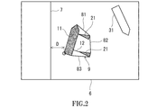
- FIG. 3 is a screen of a display device of the docking and undocking conductor support device shown in FIG. 1.
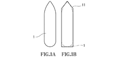
- FIG. 3A is a plan view of the ship
- FIG. 3B is a plan view showing a relationship between the ship outline and the ship.
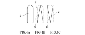
- FIG. 4A is a plan view of the tugboat
- FIG. 4B is a plan view showing the relationship between the tugboat outline and the tugboat
- FIG. 4C is a plan view showing the relationship between the tugboat outline and the tugboat of the modified example.
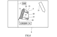
- 3 is a screen of the display device when the ship approaches the quay from the state shown in FIG. 2.
- FIG. 1 shows a takeoff/berthing conductor support device 5 (hereinafter simply referred to as “support device 5”) according to an embodiment of the present invention.
- the assisting device 5 is for a conductor when the main ship 1 is assisted by at least one (two in the present embodiment) tugboats 2 while departing or berthing.
- the support device 5 includes a communication device 51, a processing device 52, a display device 53, and an alarm device 54.
- the support device 5 may be a portable tablet computer or a notebook computer.
- the support device 5 may be installed (built in) in a ship such as the main ship 1 or the tugboat 2.
- the communication device 51 is capable of communicating with a communication device (not shown) of the main ship 1 and the tugboat 2 and a communication device (not shown) of another ship 3 existing around the main ship 1 and the tugboat 2.
- Wireless communication is performed between the communication devices, and this wireless communication may be communication via an AIS (Automatic Identification System), or may be direct communication between the ships, It may be communication between the ship and land via a ground base station.
- AIS Automatic Identification System
- the processing device 52 acquires the position information and the azimuth information of the main ship 1, the tugboat 2 and the other ship 3 via the communication device 51 and the communication device on the ship side.
- the processing device 52 has a memory such as a ROM or a RAM, a storage such as an HDD, and a CPU, and a program stored in the ROM or the HDD is executed by the CPU.
- each of the main vessel 1, the tugboat 2, and the other vessel 3 is equipped with a processing device, and the processing device stores the position information and the azimuth information of the ship equipped with the processing device in real time. To be done.
- the position information and the azimuth information are transmitted from the communication device on the ship side to the communication device 51 of the support device 5.
- the position of each ship can be measured by, for example, GNSS (Global Navigation Satellite System).
- GNSS Global Navigation Satellite System
- the position of each ship may be measured, for example, by the image analysis device using the camera installed on the main ship 1 or on the quay.
- the processing device 52 acquires the position information of each ship from the video analysis device via the communication device 51 and the communication device installed on the quay.
- the position of each ship may be measured using an optical distance measuring device installed on the quay. Also in this case, the processing device 52 acquires the position information of each ship from the distance measuring device via the communication device 51 and the communication device installed on the quay.
- Azimuth of each ship is measured by an azimuth meter installed on each ship.
- the display device 53 has a screen 6 as shown in FIG.
- the processing device 52 displays the quay line 7 on the screen 6.
- the quay line 7 is a straight line in the illustrated example, the quay line 7 may be composed of a plurality of line segments so that irregularities are formed.
- the quay position information and the shape of the quay line 7 may be stored in the processing device 52 in advance, or may be acquired from an external server via the Internet or the like.
- the processing device 52 displays the main vessel outline 11, the tugboat outline 21, and the other vessel outline 31 on the screen 6 based on the position information and the azimuth information of the main vessel 1, the tugboat 2 and the other vessel 3. In the present embodiment, the processing device 52 also displays the tow line 12 between the main ship 1 and one tugboat 2 on the screen 6.
- the processing device 52 displays the vessel outline 11 and the tugboat outline 21 on the screen 6 so as to be distinguishable from the other vessel outline 31.
- the processing device 52 displays the vessel outline 11 and the tugboat outline 21 on the screen 6 so as to be distinguishable from the other vessel outline 31.
- the outside line 11 of the vessel and the outside line 21 of the tugboat can be distinguished from the outside line 31 of the other vessel, but the method is not limited to this. Absent.
- the line types of the main vessel contour line 11 and the tugboat contour line 21 may be different from the line types of the other vessel contour line 31, and the thicknesses or colors of the main vessel contour line 11 and the tugboat contour line 21 may be different from each other.
- the thickness or color of 31 may be different.
- characters for identifying them may be provided in the vicinity of each of the ship outline 11, the tugboat outline 21, and the other ship outline 31.
- the characters "main ship” may be attached in the vicinity of the outer shape line 11 of the main ship, "tag” in the vicinity of the outer shape line 21 of the tugboat, and "other ship” may be added in the vicinity of the outer shape line 31 of the other ship.
- the shape of the ship outline 11 is not particularly limited, for example, the ship outline 11 approximates the ship 1 to a polygon having a quadrangle or more (a pentagon in the present embodiment) as shown in FIGS. 3A and 3B. It is the contour line when it is done.
- the outer shape of the main vessel 1 when determining the outer shape line 11 of the main vessel may be the outer shape at the quay height level or the maximum outer shape larger than the outer shape at the quay height level.
- the shape of the tugboat outline 21 is not particularly limited, for example, as shown in FIGS. 4A and 4B, the tugboat outline 21 approximates the tugboat 2 to a polygon having a triangle or more (triangle in the present embodiment). It is the contour line when it is done.
- the triangle has the stern as the bottom and the bow as the apex, but as shown in FIG. 4C, the bow may have the bottom and the stern as the apex.
- the outer shape of the tugboat 2 when determining the tugboat outline 21 may be the outer shape at the quay height level or the maximum outer shape that is larger than the outer shape at the quay height level.
- the shape of the other vessel outer line 31 is not particularly limited, but, for example, the other vessel outer line 31 is a contour line when the other vessel 3 is approximated to a polygon having a quadrangle or more (a pentagon in this embodiment). is there.
- the outer shape of the other ship 3 when determining the outer ship contour line 31 may be an outer shape at the quay height level or a maximum outer shape larger than the outer shape at the quay height level.
- the shapes of the vessel outline 11, the tugboat outline 21, and the other vessel outline 31 may be stored in the processing device 52 in advance, or may be acquired from an external server via the Internet or the like.
- the processing device 52 displays the extrapolation line 9 by a contour line including the main vessel outline 11 and the tugboat outline 21.
- the conductor looking at the screen 6 can recognize the range surrounded by the extrapolation line 9 as the marine vessel maneuvering area.
- the display of the extrapolation line 9 (auxiliary lines 81 to 83 described later) may be omitted.
- the extrapolation line 9 is the smallest convex polygonal contour line that includes the ship outline 11 and the tugboat outline 21. More specifically, the extrapolation line 9 is auxiliary lines 81 and 83 connecting the vertices on the ship outline 11 and the tug outline 21 and auxiliary lines 82 connecting the vertices on the tug outline 21 with each other. It is constituted by a part of the ship outline 11 and a part of the tugboat outline 21.
- each of auxiliary lines 81 and 83 between the ship outline 11 and the tug outline 21 is an arbitrary vertex on the outline 11 of the ship and an arbitrary vertex on the outline 21 of the tugboat. It may be connected to.
- the auxiliary line 82 between the tugboat outlines 21 may connect arbitrary vertices on the tugboat outline 21.
- the processing device 52 is one of the points on the vessel outline 11 (including vertices and any points between vertices) and the points on the tugboat outline 21 (including vertices and any points between vertices).
- the closest point that is closest to the line 7 and the contour line 31 of another ship is determined, and the proximity display that clearly indicates the near point is performed.
- the proximity points become conspicuous, and the conductor who looks at the screen 6 can grasp at a glance which part of the main ship 1 or the tugboat 2 should pay attention.
- the proximity display may be omitted. In this case, the determination of the proximity point can be omitted.
- the method of determining the proximity point is not particularly limited, but for example, the shortest distance from all the line segments forming the extrapolation line 9 to all the line segments forming the quay line 7 is calculated, and the extrapolation line is calculated.
- the shortest distances from all the line segments that form 9 to all the line segments that form the other ship outline 31 are determined, and the point that is the base point of the shortest shortest distance among the shortest distances is determined as the near point. May be.
- the proximity point may be determined based on the shape of 7.
- the method of proximity display is not particularly limited, but, for example, a method of marking a proximity point as shown in FIG. 2 (encircled in the figure), a method of indicating a proximity point with an arrow, a proximity point There are a method of coloring with a color different from the surrounding color, a method of blinking the proximity point, a method of increasing the display brightness of the proximity point, and the like.
- the processing device 52 calculates the shortest distance from the extrapolation line 9 to the quay line 7 and the external line 31 of another ship as the proximity distance D. For example, the processing device 52 obtains the shortest distances from all the line segments forming the extrapolation line 9 to all the line segments forming the quay line 7, and from the line segments forming the extrapolation line 9 to the outer shape of the other ship. The shortest distances to all the line segments forming the line 31 are obtained, and the shortest shortest distance among the shortest distances is calculated as the proximity distance D.
- the processing device 52 may calculate the shortest distance from the proximity point to the quay line 7 or the other ship outline 31 as the proximity distance D.
- the processing device 52 determines the shortest distance from the vessel outline 11 and the tugboat outline 21 to the quay line 8 and the other vessel outline 31 as the short distance. It may be calculated as D.
- the alarm device 54 described above emits a sound as an alarm.
- the processing device 52 causes the alarm device 54 to issue an alarm when the calculated proximity distance D becomes equal to or less than the dangerous distance. This alarm allows the conductor to know that he is in danger. Since it is not necessary to issue an alarm in the normal docking and undocking, the support device 5 may be provided with a switch that allows the conductor to select whether or not to issue an alarm. Further, the processing device 52 causes the alarm device 54 to issue an emergency warning different from the above warning when the proximity distance D becomes equal to or less than the emergency distance smaller than the dangerous distance. This emergency alert can detect that the conductor has become more dangerous.
- the processing device 52 also displays the proximity distance D on the screen 6 as shown in FIG. 6 when the calculated proximity distance D becomes equal to or less than the dangerous distance.
- the conductor looking at the screen 6 can grasp at a glance how much distance is left until the main ship 1 or the tugboat 2 collides with the quay or another ship 3.
- the proximity distance D may be always displayed on the screen 6.
- the processing device 52 displays a dangerous state on the screen 6 when the calculated proximity distance D becomes equal to or less than the dangerous distance.
- the word “danger” may be displayed on the screen 6, or the color of the screen 6 may be changed to red or the like. As a result, the conductor looking at the screen 6 can visually perceive that the dangerous state has come.
- the processing device 52 transmits a danger avoidance command to the main ship 1 and/or the tugboat 2 when the calculated proximity distance D becomes equal to or less than the danger distance.
- the main vessel 1 and/or the tugboat 2 can quickly take action to avoid danger.
- the ship outline 11, tugboat outline 21, and other ship outline 31 are displayed on the screen 6 of the display device 53. Therefore, the conductor looking at the screen 6 can grasp not only the position and direction of the main ship 1 and the tugboat 2 but also the position and direction of the other ship 3. Moreover, since the main vessel contour line 11 and the tugboat contour line 21 are displayed distinguishably from the other vessel contour line 31, the conductor can recognize the main vessel 1 and the tugboat 2 at a glance. Further, since the quay line 7 is also displayed on the screen 6, the conductor looking at the screen 6 can conduct the marine vessel maneuvering so as to avoid the collision of the main ship 1 or the tugboat 2 with the quay or another ship 3. it can.
- the processing device 52 causes the processor 52 to determine the shortest distance from the extrapolation line 9 to the quay line 7 and the other ship's outline 31 and the fixed point to the quay line 7 and the other ship's outline 31. The smaller one of the shortest distances may be calculated as the proximity distance D.
- the proximity distance is used as an index when an alarm is issued, but the proximity time may be used instead of the proximity distance.
- the proximity time may be calculated by dividing the proximity distance by the proximity speed, or may be calculated using the proximity distance and the proximity acceleration.
- the alarm is generated, the proximity distance D is displayed, the danger state is displayed, and the danger avoidance command is transmitted, but one or some or all of them are performed. May be omitted.
- the display device 53 may be omitted if only the alarm is generated. According to this configuration, the conductor cannot know the position and orientation of the other ship 3, but can detect that the quay or the other ship 3 is in a dangerous state by an alarm.
- the assisting device of the present invention is an assisting device for avoiding a collision with another ship 3 not only when the main ship 1 leaves or berths, but also when the tugboat 2 tows the main ship 1 in a harbor. Can be used as
- Vessel 11 Vessel outline 2 Tugboat 21 Tugboat outline 3 Other Vessel outline 5
- Departure/shore commander support device 52 Processing device 53
- Display device 54 Alarm device 6 Screen 7 Quayline 9 Extrapolation line
Landscapes
- Engineering & Computer Science (AREA)
- Ocean & Marine Engineering (AREA)
- Radar, Positioning & Navigation (AREA)
- Remote Sensing (AREA)
- Chemical & Material Sciences (AREA)
- Combustion & Propulsion (AREA)
- Mechanical Engineering (AREA)
- Physics & Mathematics (AREA)
- General Physics & Mathematics (AREA)
- Traffic Control Systems (AREA)
Abstract
離着岸指揮者支援装置は、少なくとも1隻のタグボートで本船がアシストされながら離岸または着岸する際の指揮者用のものであり、画面(6)を有する表示装置と、処理装置を含む。処理装置は、本船、タグボートおよび他船の位置情報および方位情報を取得し、前記位置情報および前記方位情報に基づいて、本船外形線(11)、タグボート外形線(21)および他船外形線(31)を画面(6)上に表示するとともに、画面(6)上に岸壁線(7)を表示する。さらに、処理装置は、本船外形線(11)およびタグボート外形線(21)を他船外形線(31)から識別可能に画面(6)上に表示する。
Description
本発明は、離着岸指揮者支援装置、およびこれが装備された船舶に関する。また、本発明は、離着岸指揮者支援方法に関する。
従来から、少なくとも1隻のタグボートで本船がアシストされながら離岸または着岸する際には、指揮者によってタグボートおよび/または本船に対する操船指揮が行われていた。指揮者は、水先案内人(パイロット)である場合もあるし、本船の船長である場合もある。
近年では、そのような操船指揮を指揮者が容易に行えるようにするために、離着岸指揮者支援装置が提案されている。例えば、特許文献1の図29には、水先案内人用のポータブルタブレットコンピュータが記載されている。このタブレットコンピュータの画面上には、本船およびタグボートの外形線が表示される。すなわち、指揮者は、タブレットコンピュータの画面を見れば、本船およびタグボートの位置および方位(向き)を把握することができる。また、画面上には、岸壁線も表示される。このため、指揮者は、タブレットコンピュータの画面を見ることで、本船およびタグボートが岸壁からどれだけ離れているかも把握することができる。
ところで、本船およびタグボートの周囲には、それら以外の他船も存在する。本船またはタグボートが他船と衝突することを回避するためには、指揮者が他船の位置および方位も把握したいという要望がある。
そこで、本発明は、指揮者が本船およびタグボートの位置および方位だけでなく他船の位置および方位も把握することができる離着岸指揮者支援装置を提供することを目的とする。また、本発明は、その離着岸指揮者支援装置が装備された船舶を提供することも目的とする。
なお、指揮者が本船、タグボートおよび他船の位置および方位を把握しなくても、岸壁または他船に対して危険な状態となったことを指揮者に知らせることができれば十分という考えもある。このような観点から、本発明は、指揮者が岸壁または他船に対して危険な状態となったことを察知することができる離着岸指揮者支援装置および離着岸指揮者支援方法も提供する。
前記課題を解決するために、本発明の1つの側面からの離着岸指揮者支援装置は、少なくとも1隻のタグボートで本船がアシストされながら離岸または着岸する際の指揮者用の支援装置であって、画面を有する表示装置と、前記本船および前記タグボートの位置情報および方位情報ならびに前記本船および前記タグボートの周囲に存在する他船の位置情報および方位情報を取得し、前記位置情報および前記方位情報に基づいて本船外形線、タグボート外形線および他船外形線を前記画面上に表示するとともに、前記画面上に岸壁線を表示する処理装置と、を備え、前記処理装置は、前記本船外形線および前記タグボート外形線を前記他船外形線から識別可能に前記画面上に表示する、ことを特徴とする。
上記の構成によれば、離着岸指揮者支援装置の表示装置の画面上に本船外形線、タグボート外形線および他船外形線が表示される。従って、その画面を見た指揮者は、本船およびタグボートの位置および方位だけでなく他船の位置および方位も把握することができる。しかも、本船外形線およびタグボート外形線は他船外形線から識別可能に表示されるので、指揮者は、一目で本船およびタグボートを認識することができる。また、画面上には岸壁線も表示されるので、画面を見た指揮者は、本船またはタグボートの岸壁または他船への衝突を回避するように操船指揮を行うことができる。
例えば、前記本船外形線は、前記本船を四角形以上の多角形に近似したときの輪郭線であり、前記タグボート外形線は、前記タグボートを三角形以上の多角形に近似したときの輪郭線であってもよい。
前記処理装置は、前記本船外形線上の点および前記タグボート外形線上の点のうちで前記岸壁線および前記他船外形線に最も近い近接点を決定し、前記近接点を明示する近接表示を行ってもよい。この構成によれば、近接点が目立つようになり、画面を見た指揮者が、本船またはタグボートのどの部分に注意しなければならないかを一目で把握することができる。
前記処理装置は、前記本船外形線上の点、前記タグボート外形線上の点、および前記本船外形線または前記タグボート外形線に対する相対位置が固定された固定点のうちで前記岸壁線および前記他船外形線に最も近い近接点を決定し、前記近接点を明示する近接表示を行ってもよい。この構成によれば、例えば本船から貨物が張り出している場合にその貨物の先端を固定点に設定すれば、画面を見た指揮者が、本船から張り出した貨物をも考慮して操船指揮を行うことができる。
前記処理装置は、前記画面上に、前記本船外形線および前記タグボート外形線を内包する輪郭線によって外挿線を表示してもよい。この構成によれば、画面を見た指揮者が、外挿線で囲まれた範囲を操船領域として認識することができる。
前記処理装置は、前記本船外形線および前記タグボート外形線から前記岸壁線および前記他船外形線までの最短距離を近接距離として算出し、前記近接距離が危険距離以下となったときに、警報機に警報を発生させてもよい。
あるいは、前記処理装置は、前記外挿線から前記岸壁線および前記他船外形線までの最短距離を近接距離として算出し、前記近接距離が危険距離以下となったときに、警報機に警報を発生させてもよい。
これらの構成によれば、危険な状態となったことを警報により指揮者が察知することができる。
前記処理装置は、前記本船外形線および前記タグボート外形線から前記岸壁線および前記他船外形線までの最短距離を近接距離として算出し、前記近接距離が危険距離以下となったときに、前記近接距離を前記画面上に表示してもよい。
あるいは、前記処理装置は、前記外挿線から前記岸壁線および前記他船外形線までの最短距離を近接距離として算出し、前記近接距離が危険距離以下となったときに、前記近接距離を前記画面上に表示してもよい。
これらの構成によれば、画面を見た指揮者が、本船またはタグボートが岸壁または他船へ衝突するまでどれだけの距離が残されているかを一目で把握することができる。
前記処理装置は、前記本船外形線および前記タグボート外形線から前記岸壁線および前記他船外形線までの最短距離を近接距離として算出し、前記近接距離が危険距離以下となったときに、危険な状態であることを前記画面上に表示してもよい。
あるいは、前記処理装置は、前記外挿線から前記岸壁線および前記他船外形線までの最短距離を近接距離として算出し、前記近接距離が危険距離以下となったときに、危険な状態であることを前記画面上に表示してもよい。
これらの構成によれば、画面を見た指揮者が、危険な状態となったことを視覚的に察知することができる。
前記処理装置は、前記本船外形線および前記タグボート外形線から前記岸壁線および前記他船外形線までの最短距離と、前記本船外形線または前記タグボート外形線に対する相対位置が固定された固定点から前記岸壁線および前記他船外形線までの最短距離のうちの小さい方を前記近接距離として算出してもよい。
あるいは、前記処理装置は、前記外挿線から前記岸壁線および前記他船外形線までの最短距離と、前記本船外形線または前記タグボート外形線に対する相対位置が固定された固定点から前記岸壁線および前記他船外形線までの最短距離のうちの小さい方を前記近接距離として算出してもよい。
これらの構成によれば、例えば本船から貨物が張り出している場合にその貨物の先端を固定点に設定すれば、画面を見た指揮者が、本船から張り出した貨物をも考慮して操船指揮を行うことができる。
前記処理装置は、前記近接距離が前記危険距離よりも小さな緊急距離以下となったときに、前記警報機に前記警報とは異なる緊急警報を発生させてもよい。この構成によれば、さらに危険な状態となったことを緊急警報により指揮者が察知することができる。
前記処理装置は、前記近接距離が前記危険距離以下となったときに、危険回避指令を前記本船および/または前記タグボートへ送信してもよい。この構成によれば、本船および/またはタグボートが危険を回避するための行動を迅速に行うことができる。
また、本発明の別の側面からの離着岸指揮者支援装置は、少なくとも1隻のタグボートで本船がアシストされながら離岸または着岸する際の指揮者用の支援装置であって、前記本船および前記タグボートの位置情報および方位情報ならびに前記本船および前記タグボートの周囲に存在する他船の位置情報および方位情報を取得し、前記位置情報および前記方位情報に基づいて、本船外形線およびタグボート外形線から岸壁線および他船外形線までの最短距離を近接距離として算出し、前記近接距離が危険距離以下となったときに、警報機に警報を発生させる処理装置と、を備える、ことを特徴とする。
上記の構成によれば、指揮者は他船の位置および方位を把握することはできないが、岸壁または他船に対して危険な状態となったことを警報により察知することができる。
また、本発明の離着岸指揮者支援方法は、少なくとも1隻のタグボートで本船がアシストされながら離岸または着岸する際の指揮者用の支援方法であって、前記本船および前記タグボートの位置情報および方位情報ならびに前記本船および前記タグボートの周囲に存在する他船の位置情報および方位情報を取得し、前記位置情報および前記方位情報に基づいて、本船外形線およびタグボート外形線から岸壁線および他船外形線までの最短距離を近接距離として算出する工程と、前記近接距離が危険距離以下となったときに、警報を発生する工程と、を備える、ことを特徴とする。
上記の構成によれば、指揮者は他船の位置および方位を把握することはできないが、岸壁または他船に対して危険な状態となったことを警報により察知することができる。
また、本発明は、上記の離着岸指揮者支援装置が装備された船舶も提供する。
本発明の1つの側面からの離着岸指揮者支援装置によれば、指揮者が本船およびタグボートの位置および方位だけでなく他船の位置および方位も把握することができる。また、本発明の別の側面からの離着岸指揮者支援装置および離着岸指揮者支援方法によれば、岸壁または他船に対して危険な状態となったことを指揮者が警報により察知することができる。
図1に、本発明の一実施形態に係る離着岸指揮者支援装置5(以下、単に「支援装置5」という)を示す。この支援装置5は、少なくとも1隻(本実施形態では2隻)のタグボート2で本船1がアシストされながら離岸または着岸する際の指揮者用のものである。
具体的に、支援装置5は、通信装置51、処理装置52、表示装置53および警報機54を含む。例えば、支援装置5は、ポータブルタブレットコンピュータであってもよいし、ノートブックコンピュータであってもよい。あるいは、支援装置5は、本船1やタグボート2のような船舶に装備され(組み込まれ)てもよい。
通信装置51は、本船1およびタグボート2の通信装置(図示せず)、ならびに本船1およびタグボート2の周囲に存在する他船3の通信装置(図示せず)と通信可能なものである。通信装置同士では無線通信が行われ、この無線通信は、AIS(Automatic Identification System:自動船舶識別装置)を介した通信であってもよいし、船間同士の直接通信であってもよいし、地上基地局を介した船陸間通信であってもよい。
処理装置52は、通信装置51および船側の通信装置を介して、本船1、タグボート2および他船3の位置情報および方位情報を取得する。例えば、処理装置52は、ROMやRAMなどのメモリと、HDDなどのストレージと、CPUを有し、ROMまたはHDDに記憶されたプログラムがCPUにより実行される。
図示は省略するが、本船1、タグボート2および他船3のそれぞれには処理装置が搭載されており、この処理装置には当該処理装置が搭載された船舶の位置情報および方位情報がリアルタイムで記憶される。この位置情報および方位情報が船側の通信装置から支援装置5の通信装置51へ送信される。
各船舶(本船1、タグボート2または他船3)の位置は、例えばGNSS(Global Navigation Satellite System)により測定することができる。あるいは、各船舶の位置は、例えば本船1または岸壁に設置されたカメラを用いた映像解析装置により測定されてもよい。岸壁に設置されたカメラを用いる場合、処理装置52は、通信装置51および岸壁に設置された通信装置を介して映像解析装置から各船舶の位置情報を取得する。
さらに、各船舶の位置は、岸壁に設置された光学式の距離測定装置を用いて測定されてもよい。この場合も、処理装置52は、通信装置51および岸壁に設置された通信装置を介して距離測定装置から各船舶の位置情報を取得する。
各船舶の方位は、各船舶に設けられた方位計により測定される。
表示装置53は、図2に示すような画面6を有している。処理装置52は、その画面6上に岸壁線7を表示する。図例では岸壁線7が直線となっているが、岸壁線7は凹凸が形成されるように複数の線分で構成されてもよい。岸壁の位置情報および岸壁線7の形状は、処理装置52に予め格納されてもよいし、インターネットなどを経由して外部サーバーから取得されてもよい。
さらに、処理装置52は、本船1、タグボート2および他船3の位置情報および方位情報に基づいて、本船外形線11、タグボート外形線21および他船外形線31を画面6上に表示する。本実施形態では、処理装置52が、本船1と1つのタグボート2との間の牽引線12も画面6上に表示する。
より詳しくは、処理装置52は、本船外形線11およびタグボート外形線21を他船外形線31から識別可能に画面6上に表示する。図例では、本船外形線11内およびタグボート外形線21内を塗り潰すことによって、本船外形線11およびタグボート外形線21を他船外形線31から識別可能としているが、その方法はこれに限られない。
例えば、本船外形線11およびタグボート外形線21の線種を他船外形線31の線種と異ならせてもよいし、本船外形線11およびタグボート外形線21の太さまたは色を他船外形線31の太さまたは色と異ならせてもよい。あるいは、本船外形線11、タグボート外形線21および他船外形線31のそれぞれの近傍にそれらを識別するための文字を付してもよい。例えば、本船外形線11の近傍に「本船」、タグボート外形線21の近傍に「タグ」、他船外形線31の近傍に「他船」という文字を付してもよい。
本船外形線11の形状は特に限定されるものではないが、例えば、本船外形線11は、図3Aおよび3Bに示すように、本船1を四角形以上の多角形(本実施形態では五角形)に近似したときの輪郭線である。本船外形線11を決定する際の本船1の外形は、岸壁高さレベルの外形であってもよいし、岸壁高さレベルの外形よりも大きな最大外形であってもよい。
タグボート外形線21の形状は特に限定されるものではないが、例えば、タグボート外形線21は、図4AおよびBに示すように、タグボート2を三角形以上の多角形(本実施形態では三角形)に近似したときの輪郭線である。本実施形態では、図4Bに示すように船尾を底辺、船首を頂点とする三角形であるが、図4Cに示すように船首を底辺、船尾を頂点とする三角形であってもよい。タグボート外形線21を決定する際のタグボート2の外形は、岸壁高さレベルの外形であってもよいし、岸壁高さレベルの外形よりも大きな最大外形であってもよい。
他船外形線31の形状は特に限定されるものではないが、例えば、他船外形線31は、他船3を四角形以上の多角形(本実施形態では五角形)に近似したときの輪郭線である。他船外形線31を決定する際の他船3の外形は、岸壁高さレベルの外形であってもよいし、岸壁高さレベルの外形よりも大きな最大外形であってもよい。
本船外形線11、タグボート外形線21および他船外形線31の形状は、処理装置52に予め格納されてもよいし、インターネットなどを経由して外部サーバーから取得されてもよい。
また、処理装置52は、本船外形線11およびタグボート外形線21を内包する輪郭線によって外挿線9を表示する。これにより、画面6を見た指揮者が、外挿線9で囲まれた範囲を操船領域として認識することができる。ただし、外挿線9(後述する補助線81~83)の表示は省略されてもよい。
本実施形態では、外挿線9が、本船外形線11およびタグボート外形線21を内包する最小の凸多角形の輪郭線である。より詳しくは、外挿線9は、本船外形線11上の頂点とタグボート外形線21上の頂点とを結ぶ補助線81,83と、タグボート外形線21上の頂点同士を結ぶ補助線82と、本船外形線11の一部およびタグボート外形線21の一部とによって構成される。
ただし、外挿線9の形状は適宜変更可能である。例えば、図5に示すように、本船外形線11とタグボート外形線21との間の補助線81,83のそれぞれは、本船外形線11上の任意の頂点とタグボート外形線21上の任意の頂点とを結ぶものであってもよい。同様に、タグボート外形線21同士の間の補助線82は、タグボート外形線21上の任意の頂点同士を結ぶものであってもよい。
さらに、処理装置52は、本船外形線11上の点(頂点および頂点間の任意の点を含む)およびタグボート外形線21上の点(頂点および頂点間の任意の点を含む)のうちで岸壁線7および他船外形線31に最も近い近接点を決定し、その近接点を明示する近接表示を行う。これにより、近接点が目立つようになり、画面6を見た指揮者が、本船1またはタグボート2のどの部分に注意しなければならないかを一目で把握することができる。ただし、近接表示は省略されてもよい。この場合、近接点の決定も省略可能である。
近接点を決定する方法は特に限定されるものではないが、例えば、外挿線9を構成する全ての線分から岸壁線7を構成する全ての線分までの最短距離を求めるとともに、外挿線9を構成する全ての線分から他船外形線31を構成する全ての線分までの最短距離を求め、それらの最短距離のうちで最も短い最短距離の基点となった点を近接点と決定してもよい。あるいは、本船1、タグボート2および他船3の位置情報に基づいて、本船1およびタグボート2のうちでどの船舶が岸壁または他船3に最も近いかを判定し、その船舶の方位情報および岸壁線7の形状に基づいて近接点を決定してもよい。
近接表示の方法は特に限定されるものではないが、例えば、図2に示すように近接点にマークを付ける(図例では、丸で囲む)方法、近接点を矢印で示す方法、近接点を周囲の色とは異なる色で着色する方法、近接点を点滅させる方法、近接点の表示輝度を上げる方法などがある。
また、処理装置52は、外挿線9から岸壁線7および他船外形線31までの最短距離を近接距離Dとして算出する。例えば、処理装置52は、外挿線9を構成する全ての線分から岸壁線7を構成する全ての線分までの最短距離を求めるとともに、外挿線9を構成する全ての線分から他船外形線31を構成する全ての線分までの最短距離を求め、それらの最短距離のうちで最も短い最短距離を近接距離Dとして算出する。
あるいは、処理装置52は、上述したように近接点を決定する場合は、その近接点から岸壁線7または他船外形線31までの最短距離を近接距離Dとして算出してもよい。
なお、上述したように外挿線9の表示が省略される場合は、処理装置52は、本船外形線11およびタグボート外形線21から岸壁線8および他船外形線31までの最短距離を近接距離Dとして算出すればよい。
上述した警報機54は、警報として音を発するものである。処理装置52は、算出した近接距離Dが危険距離以下となったときに、警報機54に警報を発生させる。この警報により、指揮者が危険な状態となったことを察知することができる。なお、通常の離着岸では警報の発生は不要であるので、支援装置5に、警報を発生させるか否かを指揮者が選択できるスイッチが設けられてもよい。さらに、処理装置52は、近接距離Dが危険距離よりも小さな緊急距離以下となったときに、警報機54に前記警報とは異なる緊急警報を発生させる。この緊急警報により、指揮者がさらに危険な状態となったことを察知することができる。
また、処理装置52は、算出した近接距離Dが危険距離以下となったときに、図6に示すように、近接距離Dを画面6上に表示する。これにより、画面6を見た指揮者が、本船1またはタグボート2が岸壁または他船3へ衝突するまでどれだけの距離が残されているかを一目で把握することができる。ただし、近接距離Dは、画面6上に常時表示されてもよい。
さらに、処理装置52は、算出した近接距離Dが危険距離以下となったときに、危険な状態であることを画面6上に表示する。例えば、図6に示すように、「危険」の文字を画面6上に表示してもよいし、画面6の色を赤などに変えてもよい。これにより、画面6を見た指揮者が、危険な状態となったことを視覚的に察知することができる。
さらに、処理装置52は、算出した近接距離Dが危険距離以下となったときに、危険回避指令を本船1および/またはタグボート2へ送信する。これにより、本船1および/またはタグボート2が危険を回避するための行動を迅速に行うことができる。
以上説明したように、本実施形態の支援装置5では、表示装置53の画面6上に本船外形線11、タグボート外形線21および他船外形線31が表示される。従って、その画面6を見た指揮者は、本船1およびタグボート2の位置および方位だけでなく他船3の位置および方位も把握することができる。しかも、本船外形線11およびタグボート外形線21は他船外形線31から識別可能に表示されるので、指揮者は、一目で本船1およびタグボート2を認識することができる。また、画面6上には岸壁線7も表示されるので、画面6を見た指揮者は、本船1またはタグボート2の岸壁または他船3への衝突を回避するように操船指揮を行うことができる。
(変形例)
本発明は上述した実施形態に限定されるものではなく、本発明の要旨を逸脱しない範囲で種々の変形が可能である。
本発明は上述した実施形態に限定されるものではなく、本発明の要旨を逸脱しない範囲で種々の変形が可能である。
例えば、本船外形線11またはタグボート外形線21に対する相対位置が固定された固定点が設定される場合には、近接点を決定する際に、本船外形線11上の点、タグボート外形線21上の点および固定点のうちで近接点が決定されてもよい。同様に、固定点が設定される場合は、処理装置52が、外挿線9から岸壁線7および他船外形線31までの最短距離と、固定点から岸壁線7および他船外形線31までの最短距離のうちの小さい方を近接距離Dとして算出してもよい。
本船外形線11またはタグボート外形線21に対する相対位置が固定された固定点が設定される場合としては、本船1またはタグボート2から貨物、艤装物および付帯物などが張り出す場合が想定される。例えば本船1から貨物が張り出している場合にその貨物の先端を固定点に設定すれば、画面6を見た指揮者が、本船1から張り出した貨物をも考慮して操船指揮を行うことができる。
また、前記実施形態では、警報を発生させる際の指標として近接距離が用いられていたが、近接距離の代わりに、近接時間が用いられてもよい。近接時間は、近接距離を近接速度で割って求めてもよいし、近接距離および近接加速度を用いて求めてもよい。
また、前記実施形態では、警報の発生、近接距離Dの表示、危険な状態であることの表示、および危険回避指令の送信の全てが行われていたが、それらの1つまたはいくつかあるいは全てが省略されてもよい。
さらに、警報を発生させることだけに着目すれば、表示装置53は省略されもよい。この構成によれば、指揮者は他船3の位置および方位を把握することはできないが、岸壁または他船3に対して危険な状態となったことを警報により察知することができる。
また、本発明の支援装置は、本船1が離岸または着岸する際だけでなく、港湾内でタグボート2が本船1を曳航する際にも、他船3との衝突回避を図るための支援装置として利用することができる。
1 本船
11 本船外形線
2 タグボート
21 タグボート外形線
3 他船
31 他船外形線
5 離着岸指揮者支援装置
52 処理装置
53 表示装置
54 警報機
6 画面
7 岸壁線
9 外挿線
11 本船外形線
2 タグボート
21 タグボート外形線
3 他船
31 他船外形線
5 離着岸指揮者支援装置
52 処理装置
53 表示装置
54 警報機
6 画面
7 岸壁線
9 外挿線
Claims (18)
- 少なくとも1隻のタグボートで本船がアシストされながら離岸または着岸する際の指揮者用の支援装置であって、
画面を有する表示装置と、
前記本船および前記タグボートの位置情報および方位情報ならびに前記本船および前記タグボートの周囲に存在する他船の位置情報および方位情報を取得し、前記位置情報および前記方位情報に基づいて本船外形線、タグボート外形線および他船外形線を前記画面上に表示するとともに、前記画面上に岸壁線を表示する処理装置と、を備え、
前記処理装置は、前記本船外形線および前記タグボート外形線を前記他船外形線から識別可能に前記画面上に表示する、離着岸指揮者支援装置。 - 前記本船外形線は、前記本船を四角形以上の多角形に近似したときの輪郭線であり、前記タグボート外形線は、前記タグボートを三角形以上の多角形に近似したときの輪郭線である、請求項1に記載の離着岸指揮者支援装置。
- 前記処理装置は、前記本船外形線上の点および前記タグボート外形線上の点のうちで前記岸壁線および前記他船外形線に最も近い近接点を決定し、前記近接点を明示する近接表示を行う、請求項2に記載の離着岸指揮者支援装置。
- 前記処理装置は、前記本船外形線上の点、前記タグボート外形線上の点、および前記本船外形線または前記タグボート外形線に対する相対位置が固定された固定点のうちで前記岸壁線および前記他船外形線に最も近い近接点を決定し、前記近接点を明示する近接表示を行う、請求項2に記載の離着岸指揮者支援装置。
- 前記処理装置は、前記画面上に、前記本船外形線および前記タグボート外形線を内包する輪郭線によって外挿線を表示する、請求項2~4の何れか一項に記載の離着岸指揮者支援装置。
- 前記処理装置は、前記本船外形線および前記タグボート外形線から前記岸壁線および前記他船外形線までの最短距離を近接距離として算出し、前記近接距離が危険距離以下となったときに、警報機に警報を発生させる、請求項1~4の何れか一項に記載の離着岸指揮者支援装置。
- 前記処理装置は、前記外挿線から前記岸壁線および前記他船外形線までの最短距離を近接距離として算出し、前記近接距離が危険距離以下となったときに、警報機に警報を発生させる、請求項5に記載の離着岸指揮者支援装置。
- 前記処理装置は、前記本船外形線および前記タグボート外形線から前記岸壁線および前記他船外形線までの最短距離を近接距離として算出し、前記近接距離が危険距離以下となったときに、前記近接距離を前記画面上に表示する、請求項1~4,6の何れか一項に記載の離着岸指揮者支援装置。
- 前記処理装置は、前記外挿線から前記岸壁線および前記他船外形線までの最短距離を近接距離として算出し、前記近接距離が危険距離以下となったときに、前記近接距離を前記画面上に表示する、請求項5または7に記載の離着岸指揮者支援装置。
- 前記処理装置は、前記本船外形線および前記タグボート外形線から前記岸壁線および前記他船外形線までの最短距離を近接距離として算出し、前記近接距離が危険距離以下となったときに、危険な状態であることを前記画面上に表示する、請求項1~4,6,8の何れか一項に記載の離着岸指揮者支援装置。
- 前記処理装置は、前記外挿線から前記岸壁線および前記他船外形線までの最短距離を近接距離として算出し、前記近接距離が危険距離以下となったときに、危険な状態であることを前記画面上に表示する、請求項5,7,9の何れか一項に記載の離着岸指揮者支援装置。
- 前記処理装置は、前記本船外形線および前記タグボート外形線から前記岸壁線および前記他船外形線までの最短距離と、前記本船外形線または前記タグボート外形線に対する相対位置が固定された固定点から前記岸壁線および前記他船外形線までの最短距離のうちの小さい方を前記近接距離として算出する、請求項6,8,10に記載の離着岸指揮者支援装置。
- 前記処理装置は、前記外挿線から前記岸壁線および前記他船外形線までの最短距離と、前記本船外形線または前記タグボート外形線に対する相対位置が固定された固定点から前記岸壁線および前記他船外形線までの最短距離のうちの小さい方を前記近接距離として算出する、請求項7,9,11に記載の離着岸指揮者支援装置。
- 前記処理装置は、前記近接距離が前記危険距離よりも小さな緊急距離以下となったときに、前記警報機に前記警報とは異なる緊急警報を発生させる、請求項6または7に記載の離着岸指揮者支援装置。
- 前記処理装置は、前記近接距離が前記危険距離以下となったときに、危険回避指令を前記本船および/または前記タグボートへ送信する、請求項6~14の何れか一項に記載の離着岸指揮者支援装置。
- 少なくとも1隻のタグボートで本船がアシストされながら離岸または着岸する際の指揮者用の支援装置であって、
前記本船および前記タグボートの位置情報および方位情報ならびに前記本船および前記タグボートの周囲に存在する他船の位置情報および方位情報を取得し、前記位置情報および前記方位情報に基づいて、本船外形線およびタグボート外形線から岸壁線および他船外形線までの最短距離を近接距離として算出し、前記近接距離が危険距離以下となったときに、警報機に警報を発生させる処理装置と、を備える、離着岸指揮者支援装置。 - 少なくとも1隻のタグボートで本船がアシストされながら離岸または着岸する際の指揮者用の支援方法であって、
前記本船および前記タグボートの位置情報および方位情報ならびに前記本船および前記タグボートの周囲に存在する他船の位置情報および方位情報を取得し、前記位置情報および前記方位情報に基づいて、本船外形線およびタグボート外形線から岸壁線および他船外形線までの最短距離を近接距離として算出する工程と、
前記近接距離が危険距離以下となったときに、警報を発生する工程と、
を備える、離着岸指揮者支援方法。 - 請求項1~16に記載の離着岸指揮者支援装置が装備された船舶。
Applications Claiming Priority (2)
| Application Number | Priority Date | Filing Date | Title |
|---|---|---|---|
| JP2019011534A JP2020117152A (ja) | 2019-01-25 | 2019-01-25 | 離着岸指揮者支援装置、離着岸指揮者支援方法および船舶 |
| JP2019-011534 | 2019-01-25 |
Publications (1)
| Publication Number | Publication Date |
|---|---|
| WO2020153472A1 true WO2020153472A1 (ja) | 2020-07-30 |
Family
ID=71736889
Family Applications (1)
| Application Number | Title | Priority Date | Filing Date |
|---|---|---|---|
| PCT/JP2020/002494 Ceased WO2020153472A1 (ja) | 2019-01-25 | 2020-01-24 | 離着岸指揮者支援装置、離着岸指揮者支援方法および船舶 |
Country Status (2)
| Country | Link |
|---|---|
| JP (1) | JP2020117152A (ja) |
| WO (1) | WO2020153472A1 (ja) |
Citations (3)
| Publication number | Priority date | Publication date | Assignee | Title |
|---|---|---|---|---|
| US6469664B1 (en) * | 1999-10-05 | 2002-10-22 | Honeywell International Inc. | Method, apparatus, and computer program products for alerting surface vessels to hazardous conditions |
| US20080133131A1 (en) * | 2006-11-30 | 2008-06-05 | Raytheon Company | Route-planning interactive navigation system and method |
| KR101186952B1 (ko) * | 2011-12-09 | 2012-09-28 | (주)아이엔아이 | Vts와 연계한 지능형 영상 객체 인식 선박 관제 정보시스템 |
-
2019
- 2019-01-25 JP JP2019011534A patent/JP2020117152A/ja active Pending
-
2020
- 2020-01-24 WO PCT/JP2020/002494 patent/WO2020153472A1/ja not_active Ceased
Patent Citations (3)
| Publication number | Priority date | Publication date | Assignee | Title |
|---|---|---|---|---|
| US6469664B1 (en) * | 1999-10-05 | 2002-10-22 | Honeywell International Inc. | Method, apparatus, and computer program products for alerting surface vessels to hazardous conditions |
| US20080133131A1 (en) * | 2006-11-30 | 2008-06-05 | Raytheon Company | Route-planning interactive navigation system and method |
| KR101186952B1 (ko) * | 2011-12-09 | 2012-09-28 | (주)아이엔아이 | Vts와 연계한 지능형 영상 객체 인식 선박 관제 정보시스템 |
Also Published As
| Publication number | Publication date |
|---|---|
| JP2020117152A (ja) | 2020-08-06 |
Similar Documents
| Publication | Publication Date | Title |
|---|---|---|
| JP7386041B2 (ja) | 操船支援システム及び方法 | |
| KR102269676B1 (ko) | 선박의 자동 충돌 예방 방법 및 장치 | |
| KR101693981B1 (ko) | 선박의 충돌 회피 방법 및 장치 | |
| KR101693982B1 (ko) | 선박의 충돌 회피 방법 및 장치 | |
| KR101683274B1 (ko) | 무인항공기를 이용한 선박 접안 지원 시스템 및 그 방법 | |
| CN114040886B (zh) | 确定物体位置的系统 | |
| US6469664B1 (en) | Method, apparatus, and computer program products for alerting surface vessels to hazardous conditions | |
| JP5102886B2 (ja) | 画像表示システム及び画像表示方法及びプログラム | |
| KR101973556B1 (ko) | 전자해도를 이용한 소형선박 항해 및 조업 보조 시스템 | |
| KR101549513B1 (ko) | 증강현실을 이용한 선박 충돌 방지 겸용 선박 사고 기록 시스템 및 방법 | |
| WO2014017422A1 (ja) | 船舶監視装置 | |
| JP2016055772A (ja) | 自船周囲表示装置及び自船周囲情報表示方法 | |
| NO341775B1 (en) | Dynamic tug winch control | |
| JPWO2019093416A1 (ja) | 船舶の航行支援システム | |
| CN110087985B (zh) | 拖船接近控制 | |
| JP2021187282A (ja) | 工事用船舶の航行監視システムおよび航行監視方法 | |
| JP7437129B2 (ja) | 操船支援システム | |
| KR102877907B1 (ko) | 조선 시스템 및 조선 방법 | |
| JP2020117152A (ja) | 離着岸指揮者支援装置、離着岸指揮者支援方法および船舶 | |
| JP5983922B2 (ja) | 船舶監視装置 | |
| JP7846567B2 (ja) | 操船システム及び操船方法 | |
| AU2019100960B4 (en) | Collision warning system for a boat | |
| KR102777047B1 (ko) | 위치 모니터링이 가능한 선박 및 이의 위치 모니터링 방법 | |
| Baldauf et al. | New Sensor Technology Integration for safe and efficient e-Navigation | |
| JP3103945U (ja) | パイロット業務支援装置 |
Legal Events
| Date | Code | Title | Description |
|---|---|---|---|
| 121 | Ep: the epo has been informed by wipo that ep was designated in this application |
Ref document number: 20745813 Country of ref document: EP Kind code of ref document: A1 |
|
| NENP | Non-entry into the national phase |
Ref country code: DE |
|
| 122 | Ep: pct application non-entry in european phase |
Ref document number: 20745813 Country of ref document: EP Kind code of ref document: A1 |