WO2020153404A1 - 固体燃料バーナ - Google Patents
固体燃料バーナ Download PDFInfo
- Publication number
- WO2020153404A1 WO2020153404A1 PCT/JP2020/002138 JP2020002138W WO2020153404A1 WO 2020153404 A1 WO2020153404 A1 WO 2020153404A1 JP 2020002138 W JP2020002138 W JP 2020002138W WO 2020153404 A1 WO2020153404 A1 WO 2020153404A1
- Authority
- WO
- WIPO (PCT)
- Prior art keywords
- fuel
- swirler
- flow path
- nozzle
- fuel nozzle
- Prior art date
- Legal status (The legal status is an assumption and is not a legal conclusion. Google has not performed a legal analysis and makes no representation as to the accuracy of the status listed.)
- Ceased
Links
Images


Classifications
-
- F—MECHANICAL ENGINEERING; LIGHTING; HEATING; WEAPONS; BLASTING
- F23—COMBUSTION APPARATUS; COMBUSTION PROCESSES
- F23D—BURNERS
- F23D1/00—Burners for combustion of pulverulent fuel
- F23D1/02—Vortex burners, e.g. for cyclone-type combustion apparatus
Definitions
- the present invention relates to a solid fuel burner that conveys and burns solid fuel, and particularly to a solid fuel burner suitable for fuel particles having a large particle size such as biomass particles.
- the fuel concentration is locally increased.
- a velocity component toward the nozzle inner wall surface is imparted to the mixed fluid of the fuel carrier gas and the fuel particles so that the fuel particles are distributed along the nozzle inner wall surface.
- a fuel concentrator (mechanism) for concentration is often provided.
- a first swirler for imparting swirl to a mixed fluid at the center of a fuel nozzle (sometimes referred to as a primary air nozzle) (9) ( 6) and a technique of providing a second swirler (7) that imparts a swirl in the opposite direction to the first swirler (6).
- the first swirler (6) strongly swirls the mixed fluid to move the solid fuel particles to the outer peripheral side of the fuel nozzle (along the inner wall surface of the fuel nozzle).
- the second swirler (7) imparts a swirl in the direction opposite to that of the first swirler (6) to weaken the swirl of the mixed fluid.
- the solid fuel particles are kept concentrated around the flame holder (10) installed at the opening of the burner and the tip of the fuel nozzle, and even when the fuel concentration supplied to the burner is low and the load is low.
- the ignitability of the fuel particles is increased and the flame stability is improved.
- the swirl-weakened mixed fluid is ejected from the opening, so that the mixed fluid does not spread excessively in the furnace, and the mixing with the combustion gas (air) such as secondary air and tertiary air is made gentle. Generation of nitrogen oxides (NOx) is suppressed.
- Patent No. 6231047 (“0004”, “0048” to “0061”, FIGS. 1 to 3 and 21) Japanese Patent No. 4919844 (“0021” to “0023”) Japanese Unexamined Patent Publication No. 2010-242999 (“0033”)
- pellets As a fuel for mixed combustion in coal (pulverized coal)-fired boilers for thermal power generation, wood-based raw materials in pellet form are often used.
- the pellets are not used as they are, but carry the fuel particles obtained by crushing and classifying with an improved mill (crusher/classifier) based on a coal mill (pulverized coal machine) as a crushing device.
- the gas is conveyed to the solid fuel burner, the mixed fluid of the fuel particles and the carrier gas is supplied to the burner, and is burned similarly to the pulverized coal.
- biomass fuel is more difficult to be finely pulverized than coal, and the pulverization power of the mill is large (about 10 times the power of coal is required to make the particle size of wood chips of 50 mm the same as that of coal). It is difficult to atomize to the same level as pulverized coal. Further, if the biomass fuel is pulverized, the possibility of rapid combustion increases, and preventive measures are also required. For these reasons, biomass fuel is discharged from the mill in a state of particles that are considerably coarser than coal (see Patent Document 2; Japanese Patent No. 4919844, Patent Document 3; Japanese Patent Laid-Open No. 2010-242999, etc.). As a result, coarse-grained biomass fuel has a lower ignitability than pulverized coal.
- the flow passage cross-sectional area of the fuel nozzle is small on the upstream side, that is, on the side of the fuel transfer system (connection part with the fuel transfer pipe) connected from the crushing device, and on the downstream side, that is, on the furnace opening side compared to the upstream side. It is possible to improve the ignitability by increasing the flow rate to reduce the flow rate.
- Patent Document 3 includes a venturi and a fuel concentrator that imparts a velocity component in a direction away from the center of the fuel nozzle as a mechanism for concentrating the fuel of the mixed fluid, and Disclosed is a solid fuel burner having an inner diameter greater than the inner diameter of the upstream end of the venturi.
- a curved pipe portion is provided on the upstream side of the fuel nozzle of the solid fuel burner described in Patent Document 3, and at the connection portion with the fuel transfer pipe from the mill to the burner.
- the mixed fluid flows in a flow path that communicates with the straight pipe portion of the fuel nozzle from the fuel conveying pipe through the curved pipe portion.
- the high-speed fluid passing through the curved pipe portion collides with the upper surface and then easily flows downward so as to be reflected.
- the spindle-shaped fuel concentrator gives a velocity component in the direction away from the center of the fuel nozzle, and the fuel particles are biased in the circumferential direction, and depending on the setting of the length of each part of the fuel nozzle, etc. It has been found that the flow velocity of the fluid above the fuel nozzle tends to be excessively low.
- the present invention relates to a solid fuel burner, in which a fuel provided in a fuel nozzle is used even when a coarse-grained fuel obtained by pulverizing a biomass fuel (such as pelletized wood-based raw material) with a mill is used.
- a biomass fuel such as pelletized wood-based raw material
- the solid fuel burner of the invention according to claim 1 is A fuel nozzle that opens toward the furnace, where a mixed fluid of solid fuel and its carrier gas flows, A combustion gas nozzle that is arranged on the outer peripheral side of the fuel nozzle and ejects combustion gas.
- a solid fuel burner provided with a fuel concentrator that is provided on the center side of the fuel nozzle and applies a velocity component in a direction away from the center of the fuel nozzle to the mixed fluid,
- the fuel concentrator has a plurality of vanes that impart swirl to the mixed fluid, and each vane is arranged at a distance from the inner surface of the fuel nozzle without being entirely fixed inside the fuel nozzle.
- a first swirler disposed upstream in the flow direction of the mixed fluid, and a swirl direction of the plurality of blades disposed downstream in the flow direction of the mixed fluid with respect to the first swirler.
- a second swirler having a direction opposite to that of the first swirler,
- a flow path partitioning member that partitions the flow path of the fuel nozzle into an inner side and an outer side in a flow path cross section is provided downstream of the second swirler in the flow direction of the mixed fluid.
- the invention according to claim 2 provides the solid fuel burner according to claim 1,
- the outer diameters of the first swirler and the second swirler are equal to or less than the inner diameter of the upstream end of the flow path partitioning member, It is characterized by
- the invention according to claim 3 provides the solid fuel burner according to claim 1,
- the flow path partitioning member is characterized in that the inner diameter of the upstream end is larger than the inner diameter of the downstream end.
- the invention according to claim 4 is the solid fuel burner according to claim 3,
- the outer diameter of the second swirler is smaller than the inner diameter of the upstream end of the flow path partitioning member and larger than the inner diameter of the downstream end thereof.
- the solid fuel burner of the invention according to claim 5 is A fuel nozzle that opens toward the furnace, where a mixed fluid of solid fuel and its carrier gas flows, A combustion gas nozzle that is arranged on the outer peripheral side of the fuel nozzle and ejects combustion gas.
- a solid fuel burner provided with a fuel concentrator, which is provided on the center side of the fuel nozzle, and applies a velocity component in a direction away from the center of the fuel nozzle to the mixed fluid,
- the fuel concentrator has a plurality of vanes that impart swirl to the mixed fluid, and each vane is arranged at a distance from the inner surface of the fuel nozzle without being entirely fixed inside the fuel nozzle.
- a first swirler disposed upstream in the flow direction of the mixed fluid, and a swirl direction of the plurality of blades disposed downstream in the flow direction of the mixed fluid with respect to the first swirler.
- a second swirler having a direction opposite to that of the first swirler,
- the flow path of the fuel nozzle has an upstream portion of which the inner diameter is the same or monotonically increases on the upstream side of the first swirler, and a pipe expanding portion which communicates with the downstream side of the upstream portion and whose inner diameter gradually increases.
- the invention according to claim 6 provides the solid fuel burner according to claim 5, At least a part of the first swirler is located in a range of an upstream portion of the fuel nozzle flow path, At least a part of the second swirler is located in a range of a downstream portion of the fuel nozzle flow path.
- the invention according to claim 7 provides the solid fuel burner according to claim 6,
- a flow path partitioning member that partitions the flow path of the fuel nozzle into an inner side and an outer side in a flow path cross section is provided in a range of a downstream portion of the fuel nozzle flow path.
- the invention according to claim 8 provides the solid fuel burner according to claim 7,
- the flow path partitioning member has a shape in which the inner diameter of the upstream end is larger than the inner diameter of the downstream end,
- the outer diameter of the second swirler is smaller than the inner diameter of the upstream end of the flow path partitioning member and larger than the inner diameter of the downstream end of the flow path partitioning member.
- the invention according to claim 9 is the solid fuel burner according to any one of claims 1 to 8, wherein: The outer diameter of each of the swirlers is less than the inner diameter of the upstream portion of the fuel nozzle passage.
- biomass fuel such as pellets of wood-based raw material
- biomass fuel can be used in the solid fuel burner. Even when using fuel with coarse particles such as those obtained by pulverizing with a mill, it is possible to secure the fuel concentration effect by the fuel concentrator installed in the fuel nozzle and improve ignitability and flame stability. it can.
- the carrier gas can be dispersed to the inner peripheral side while being brought to the outer peripheral side, the effect of concentrating the fuel on the outer peripheral side can be improved.
- the flow velocity of the mixed fluid passing through the flow path partitioning member on the gas side can be further reduced, and the ignitability and flame holding property can be improved.
- the inner diameter of the outer peripheral side (nozzle inner wall side) flow passage is reduced toward the nozzle opening, so that the mixed fluid between the flow passage partitioning member and the inner wall of the nozzle is
- the flow passage cross-sectional area is expanded, the flow velocity of the fuel particles is reduced, and ignitability and flame stability can be further improved.
- the effect of canceling the swirl by the second swirler can be spread over the entire radial direction on the inner peripheral side (nozzle center side) of the flow path partitioning member. Therefore, the mixed fluid with weakened swirling is ejected from the burner opening, and the mixed fluid does not spread excessively in the furnace, and the mixing with the combustion gas (air) such as secondary air and tertiary air is moderated.
- the effect of suppressing the generation of nitrogen oxides (NOx) can be enhanced.
- the fuel nozzle is a straight tube of the same or monotonically increasing upstream of the first swirler, and is connected to the downstream side of the first swirler, and the pipe expanding portion whose inner diameter gradually increases, It has a straight tubular downstream part that communicates with the downstream side of the expansion section and has an inner diameter larger than that of the upstream side.In the transfer pipe, it is conveyed at a high flow rate so as not to cause the retention of large-sized fuel particles. At the same time, since the flow passage cross-sectional area is larger on the furnace opening side than on the upstream side and the flow velocity is reduced, it is possible to improve the ignitability and flame stability while ensuring the fuel concentration effect.
- the first swirler effectively causes the concentration of the fuel particles outside the fuel nozzle (along the inner wall), and the second swirler effectively cancels the swirl.
- the blades of the first swirler extend over the upstream portion in at least a part of the longitudinal direction, and it is possible to efficiently give the radially outward velocity component to the mixed fluid flowing in the upstream portion. it can.
- the effect of concentrating the fuel particles on the outer side of the fuel nozzle (along the inner wall) can be enhanced and the effect is less likely to disappear, as compared with the case where the flow path partitioning member is not provided.
- the combination of the first swirler and the second swirler as the fuel concentrator it becomes unnecessary to impart excessive swirl and cancel it. Therefore, the pressure loss of the burner can be reduced. Further, the combination of the first swirler and the second swirler as the fuel concentrator can be made compact to shorten the total length of the fuel nozzle, which leads to a reduction in the amount of members used.
- the fuel concentrator can be pulled out in the axial direction of the fuel nozzle and removed to perform maintenance and inspection. Therefore, the workability of maintenance and inspection can be improved.
- FIG. 1 is an overall explanatory diagram of a combustion system according to a first embodiment of the present invention.
- FIG. 2 is an explanatory diagram of the solid fuel burner of the first embodiment.
- FIG. 3 is a view seen from the direction of arrow III in FIG. 4A and 4B are explanatory views of the flow path partitioning member of Example 1
- FIG. 4A is a side view
- FIG. 4B is a sectional view taken along line IVB-IVB in FIG. 4A
- FIG. 4B is a diagram corresponding to FIG. 4B of the first modification
- FIG. 4D is a diagram corresponding to FIG. 4B of the second modification.
- FIG. 5 is an explanatory diagram of a comparative example.
- FIG. 6 is an explanatory diagram of simulation results.
- FIG. 5 is an explanatory diagram of a comparative example.
- FIG. 6 is an explanatory diagram of simulation results.
- FIG. 7 is an explanatory view of a boiler (combustion device) equipped with the solid fuel burner of the present invention
- FIG. 7(A) is a can front side and a can back side of the three-stage solid fuel burner before and after the can (boiler).
- FIG. 7B and FIG. Of the solid fuel burner of FIG. 7, FIGS. 7(C) and 7(E) are explanatory views of the case where the solid fuel burner of the present invention is used, in which biomass fuel is used in the uppermost stage behind the can. Is.
- FIG. 1 is an overall explanatory diagram of a combustion system according to a first embodiment of the present invention.
- a biomass fuel solid fuel
- the biomass fuel of the bunker 4 is crushed by a mill (crusher) 5.
- the pulverized fuel is supplied to the solid fuel burner 7 of the boiler (furnace) 6 through the fuel pipe 8 and burned.
- a plurality of solid fuel burners 7 are installed in the boiler 6.
- the exhaust gas discharged from the boiler 6 is denitrated by the denitration device 9.
- the denitrated exhaust gas passes through the air preheater 10.
- the air preheater 10 heat exchange between the air sent from the blower 11 and the exhaust gas is performed. Therefore, the temperature of the exhaust gas is lowered and the air from the blower 11 is heated.
- Air from the blower 11 is supplied to the solid fuel burner 7 and the boiler 6 as combustion air through the air pipe 12.
- the exhaust gas that has passed through the air preheater 10 is recovered in heat when passing through the gas gas heater (heat recovery device) 13, and is cooled down.
- the exhaust gas that has passed through the gas gas heater (heat recovery device) 13 is collected and removed by a dry dust collector 14 such as dust in the exhaust gas.
- the exhaust gas that has passed through the dry dust collector 14 is sent to the desulfurization device 15 to be desulfurized.
- the exhaust gas that has passed through the desulfurization device 15 is collected and removed by the wet dust collector 16 such as dust in the exhaust gas.
- the exhaust gas that has passed through the wet dust collector 16 is reheated by the gas gas heater (reheater) 17.
- the exhaust gas that has passed through the gas gas heater (reheater) 17 is exhausted to the atmosphere from the chimney 18.
- the mill 5 itself may have various conventionally known configurations, and is described in, for example, Japanese Unexamined Patent Publication No. 2010-242999, so detailed description thereof will be omitted.
- FIG. 2 is an explanatory diagram of the solid fuel burner of the first embodiment.
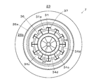
- FIG. 3 is a view seen from the direction of arrow III in FIG. 2 and 3, the solid fuel burner 7 of the first embodiment has a fuel nozzle 21 through which a carrier gas flows.
- the downstream end opening of the fuel nozzle 21 is provided in the wall surface (furnace wall, water tube wall) 23 of the furnace 22 of the boiler 6.
- the fuel nozzle 21 has an elbow 20 as an example of a curved pipe portion formed at the upstream end in the flow direction of the carrier gas.
- the elbow 20 is bent so that the flow direction of the mixed fluid is bent by approximately 90°.
- the fuel pipe 8 is connected to the upstream end of the elbow 20.
- the fuel nozzle 21 is formed in a hollow cylindrical shape, and inside the fuel nozzle 21, a flow path 24 is formed in which a mixed fluid of solid fuel (crushed biomass fuel) and carrier gas flows.
- An inner combustion gas nozzle (secondary combustion gas nozzle) 26 that ejects combustion air to the furnace 22 is installed on the outer periphery of the fuel nozzle 21. Further, an outer combustion gas nozzle (third combustion gas nozzle) 27 is installed on the outer peripheral side of the inner combustion gas nozzle 26. The combustion gas nozzles 26 and 27 eject the air from the wind box 28 into the furnace 22.
- a guide vane 26a is formed at the downstream end of the inner combustion gas nozzle 26 so as to incline radially outward with respect to the center of the fuel nozzle 21 (the diameter increases toward the downstream side). ..
- a throat portion 27a along the axial direction and an enlarged portion 27b parallel to the guide vane 26a are formed in the downstream portion of the outer combustion gas nozzle 27. Therefore, the combustion air ejected from each of the combustion gas nozzles 26 and 27 is ejected so as to diffuse from the center in the axial direction.
- a flame stabilizer 31 is supported at the opening at the downstream end of the fuel nozzle 21.
- an ignition burner (oil gun) 32 is disposed so as to penetrate through the center of the flow passage cross section of the fuel nozzle 21.
- the ignition burner 32 is supported while penetrating the collision plate 32 a supported by the collision plate flange 20 a of the fuel nozzle 21.
- the fuel nozzle 21 is provided with a straight pipe portion 21a, which is an example of an upstream portion, on the downstream side of the elbow 20 with respect to the flow direction of the mixed fluid.
- the straight pipe portion 21a is formed in a straight pipe shape having the same cross-sectional area of the flow path 24.
- an enlarged portion 21b whose inner diameter (that is, a cross-sectional area) is enlarged toward the downstream side is connected.
- a straight tubular downstream portion 21c having the same cross-sectional area toward the downstream end is connected to the downstream side of the enlarged portion 21b.
- the angle ⁇ 1 formed by the inner wall of the enlarged portion 21b with respect to the extension line of the straight pipe portion 21a is set to 10° to 15°.
- ⁇ 1 is preferably 10° to 15° because there is a problem that fuel tends to accumulate.
- a straight pipe portion 21a upstream portion
- a enlarged portion 21b enlarged portion
- a downstream portion 21c downstream portion
- a fuel concentrator 34 is arranged inside the fuel nozzle 21.
- the fuel concentrator 34 is supported by the ignition burner 32.
- the fuel concentrator 34 has an upstream first swirler 34a and a downstream second swirler 34b.
- the first swirler 34a has a plurality of first swirl vanes 34c formed in a spiral shape with the ignition burner 32 as an axis.
- the second swirler 34b has a second swirl vane 34d that is inclined in a direction opposite to the first swirl vane 34c (a spiral shape of reverse winding).
- the swirl vanes 34c and 34d are not fixed to the inner surface of the fuel nozzle 21, and the outer circumferential ends of the swirl vanes 34c and 34d are installed apart from the inner surface of the fuel nozzle 21.
- the mixed fluid of the fuel and the carrier gas passes through the first swirler 34a, the swirl toward the outer side in the radial direction is imparted. Therefore, the fuel is concentrated toward the inner wall surface of the fuel nozzle 21. Then, when passing through the second swivel device 34b, a reverse swirl is imparted and the swirl is weakened. Therefore, on the downstream side of the fuel concentrator 34, the mixed fluid has a flow in which the fuel is concentrated on the outer peripheral side and is close to a straight flow.
- the first swirler 34a When arranging the first swirler 34a and the second swirler 34b in the fuel nozzle 21 having such a pipe-expanding shape, the first swirler 34a is arranged outside the fuel nozzle 21 (along the inner wall). Regarding the concentration of the fuel particles and the second swirler 34b, the arrangement in the fuel nozzle should be appropriately set so that the swirl cancellation effectively acts and the fuel concentration effect and the swirl cancellation effect are less likely to be impaired. Is desirable.
- the blades 34c of the first swirler 34a be in contact with the upstream portion (the straight pipe portion 21a) in the longitudinal direction (at least a part thereof). As a result, the velocity component radially outward (toward the inner wall of the nozzle) can be efficiently given to the mixed fluid flowing through the upstream portion 21a.
- the downstream end of the vane 34c in the longitudinal direction is located upstream of the fuel nozzle 21 (the upstream straight pipe portion 21a) and the enlarged portion 21b (upstream portion). It is desirable to be provided so as to be located at the same position as the boundary portion with the expanded portion communicating with the above) or on the downstream side thereof, that is, on the expanded portion 21b side. This is to reduce the rebound of the fuel particles from the inner wall of the nozzle and to enhance the concentration effect.
- the canceling action of the swirl by the second swirler 34b can be suppressed without being significantly enhanced, and the inside of the flow path of the fuel nozzle 21 through the two swirlers 34a and 34b can be suppressed. It is also effective in suppressing an increase in pressure loss.
- the blades 34d of the second swirler 34b hang on the downstream portion 21c (downstream straight pipe portion) in the longitudinal direction (at least a part thereof). That is, it is desirable that the blade is provided so that the downstream end portion in the longitudinal direction (axial direction of the fuel nozzle 21) of the blade is located on the downstream portion 21c (downstream straight pipe portion) side of the fuel nozzle 21.
- the second swivel device 34b that has a sufficient effect of canceling the swivel with a proper distance from the first swirl device 34a while suppressing the pressure loss.
- the outer diameter D W1 of the first swirl vane 34c is set to 70% as an example with respect to the inner diameter D1 of the straight pipe portion, but it is preferably set to 60% to 85%. .. If it is less than 60%, the swirling imparted is weak and the fuel concentration effect is low. If it exceeds 85%, the swirling flow may become too strong.
- the outer diameter D W2 of the second swirl vane 34d is formed to be larger than the outer diameter D W1 of the first swirl vane 34c (that is, D W2 ⁇ D W1 ). Further, in the first embodiment, the outer diameter D W2 is smaller than the inner diameter D 1.
- the outer diameter D W2 of the second swirl vane 34d is set to 65%, for example, with respect to the inner diameter D2 of the downstream portion 21c, and is preferably set to 55% to 80%. If it is less than 55%, the effect of canceling the turn by the reverse turn becomes low. Further, if it exceeds 80%, it becomes difficult to pull out the ignition burner 32 from the fuel nozzle 21 at the time of maintenance. Therefore, when the ignition burner 32 is not pulled out, the outer diameter D W2 can exceed 80% of the inner diameter D2, or the outer diameter D W2 ⁇ the inner diameter D1.
- the distance from the downstream end fs of the fuel nozzle 21 to the downstream end of the straight pipe portion 21a is L1 with respect to the flow direction of the mixed flow, and the fuel nozzle 21
- the distance from the downstream end fs to the upstream end of the downstream portion 21c is L2
- the distance from the downstream end fs of the fuel nozzle 21 to the central portion of the second swirler 34b is L4.
- 0 ⁇ D2 it is preferable to set 0 ⁇ D2 to 0.5 ⁇ D2.
- the diameter ratio is relatively reduced, and the fuel concentration effect is reduced.
- it exceeds 0.5 the fuel deflected toward the outer peripheral side by the swirl imparted by the first swirler 34a collides with the inner peripheral surface of the fuel nozzle 21 and is reflected in the radial inner side. The fuel concentration effect is reduced.
- the first swirler 34a is located within the range of the straight pipe portion (upstream portion) 21a of the fuel nozzle 21. Further, at least a part of the second swirler 34b is located in the range of the downstream portion 21c of the fuel nozzle 21. Therefore, when disposing the first swirler 34a and the second swirler 34b in the fuel nozzle 21 having the expanded pipe shape (enlarged portion 21b), the first swirler 34a is disposed outside the fuel nozzle (along the inner wall). In the second swirler 34b, the fuel particles are concentrated to (4) and the swirling is effectively canceled, and the fuel is less likely to be damaged.
- the blades 34c of the first swirler 34a overlap the upstream portion (straight pipe portion 21a) in the longitudinal direction (at least a part thereof), and the first swirler 34a efficiently and radially with respect to the mixed fluid flowing in the upstream portion 21a.
- An outward velocity component (toward the inner wall of the nozzle) can be given.
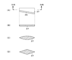
- FIG. 4A and 4B are explanatory views of the flow path partitioning member of Example 1, FIG. 4A is a side view, FIG. 4B is a sectional view taken along line IVB-IVB in FIG. 4A, and FIG. 4B is a diagram corresponding to FIG. 4B of the first modification, and FIG. 4D is a diagram corresponding to FIG. 4B of the second modification. 2 and 3, a flow path partitioning member 36 is arranged on the downstream side of the fuel concentrator 34.
- the flow path partitioning member 36 is supported on the inner surface of the fuel nozzle 21 by a supporting member 37.
- the flow path partitioning member 36 of the first embodiment is formed in a partially conical shape (conical shape) whose inner diameter decreases from the upstream end S1 toward the downstream end S2.
- the flow path partitioning member 36 partitions the flow path 24 into the outer flow path 24a and the inner flow path 24b.
- the support member 37 is formed in a plate shape extending in the radial direction. A plurality of support members 37 are arranged at intervals in the circumferential direction. In FIG. 3, in the first embodiment, the support member 37 is arranged at a position corresponding to between the inner circumferential side protrusions 31 a of the flame stabilizer 31.
- a flow path partitioning member 36 is arranged on the downstream side of the fuel concentrator 34. Therefore, in the solid fuel burner 7 of the first embodiment, the flow passage partitioning member 36 is arranged on the downstream side where the swirling of the fluid on the nozzle center side is weakened by the second swirler 34b, and the flow passage is on the outer peripheral side ( It is divided and separated into the inner wall side of the nozzle) and the inner peripheral side (center side of the nozzle). Therefore, most of the fuel concentrated toward the inner peripheral wall of the fuel nozzle 21 by the first swirl vane 34c of the fuel concentrator 34 is supplied to the outer flow path 24a.
- the flow path partitioning member 36 is unlikely to interfere with the flow of particles directed outward in the radial direction by the fuel concentrator 34, and the fuel flowing outward in the radial direction in the outer flow path 24a is reflected by the inner peripheral wall to re-enter the central axis. Even if it tries to go to the side, it is blocked by the flow path partitioning member 36. Therefore, the first swirler 34a suppresses redispersion of the fuel particles once concentrated on the outer peripheral side (nozzle inner wall side), and the concentration effect is maintained up to the vicinity of the nozzle opening. Therefore, compared to the configuration described in Patent Document 1 that does not have the flow path partitioning member 36, the fuel concentration effect can be secured even when using solid fuel particles obtained by pulverizing biomass fuel having poor ignitability.
- the fuel concentrator 34 is not entirely fixed to the inner surface of the fuel nozzle 21.
- the supporting portion is worn by the collision of the concentrated fuel particles. Therefore, it is necessary to form the supporting portion with a special material having wear resistance, which causes a problem of increased cost.
- the fuel concentrator 34 is not supported by the fuel nozzle 21, there is no part to be worn, and an increase in cost can be suppressed.
- the configuration is not such that the fuel concentrator that provides the velocity component in the direction away from the center of the fuel nozzle is disposed on the downstream side. That is, it differs from the configuration described in Patent Document 3.
- the direction is reversed such that the velocity component of the fuel particles is once imparted to the center of the nozzle by the venturi and then the velocity component of the direction away from the center of the fuel nozzle is imparted by the spindle-shaped fuel concentrator.
- the mixed fluid does not undergo the action toward the center of the fuel nozzle 21 in the flow path that passes through the curved tube portion, and the first swirler 34a Since the velocity component in the direction away from the center of the fuel nozzle 21 is applied and the concentration action is completed in one step, the length of the fuel nozzle 21 can be shortened as compared with the configuration described in Patent Document 3. If the length of the fuel nozzle 21 can be shortened, the degree of freedom in installing the burner is increased, and there is an advantage that interference with other out-of-reactor equipment, piping, and structures can be avoided.
- the solid fuel burner 7 of the first embodiment has the flow path partitioning member 36, the effect of concentrating the fuel particles to the outside of the fuel nozzle 21 (along the inner wall) is high, and the effect does not easily disappear.
- the combination of the first swirler 34a and the second swirler 34b as the fuel concentrator 34 it is not necessary to impart excessive swirl and cancel it, which is effective in reducing the pressure loss of the burner.
- the combination of the first swirler 34a and the second swirler 34b as the fuel concentrator 34 can be made compact to shorten the overall length of the fuel nozzle 21, leading to a reduction in the amount of use of members.
- the concentration of the fuel particles along the inner wall of the fuel nozzle 21 and the burner opening thereof with respect to the mixed fluid containing the fuel particles having a coarse particle size can be realized with less turning. That is, the fuel particles once concentrated along the inner wall of the fuel nozzle 21 are less likely to be redispersed toward the center of the nozzle, or the ignitability near the flame stabilizer 31 at the opening end is improved by reducing the flow velocity, and thus the first swirler It is possible to make the strength of turning in 34a, that is, the angle of the first turning vane 34c and the like relatively gentle.
- the flow path partitioning member 36 is formed in a conical shape, and the flow velocity of the fluid passing between the flow path partitioning member 36 and the fuel nozzle 21 while passing through the flow path partitioning member 36. Is reduced. Then, the concentrated fuel is supplied to the furnace 6 with the flow velocity reduced. Therefore, the ignitability can be secured even with a biomass fuel having a low ignitability.
- the cross-sectional area of the outer flow path 24a at the downstream end S2 is the upstream end S1 so that the flow speed of the mixed fluid at the downstream end S2 is lower than the flow speed at the upstream end S1.
- It has a conical shape that is larger than the cross-sectional area of the outer flow path 24a. That is, in Example 1, the inner diameter D S1 at the upstream end of the flow path partitioning member 36 is formed larger than the inner diameter D S2 at the downstream end. With such an inclined shape, the solid fuel particles are more likely to move along the inclined surface and less likely to be deposited on the upper surface than in the case of the cylindrical shape along the axial direction.
- the inclination angle ⁇ 2 with which the flow path partitioning member 36 is inclined with respect to the axial direction is preferably 10° to 15°. The reason why it is preferable to set ⁇ 2 to 10° to 15° is the same as in the case of ⁇ 1.
- the inner diameter D S1 of the upstream end S1 of the flow path partitioning member 36 is set to be equal to or larger than the outer diameter D W1 of the first swirl vane 34c and the outer diameter D W2 of the second swirl vane 34d.
- D S1 ⁇ D W2 the carrier gas also flows into the outer peripheral flow path of D S1 , and the effect of concentrating the particle concentration is reduced. Therefore, by setting D S1 ⁇ D W2 , the particles flow into the outer peripheral side and the carrier gas is distributed into the outer peripheral and inner peripherals, so that there is an effect of concentrating the concentration of particles passing through the flow path partitioning member 36.
- the effect of canceling the swirl by the second swirler 34b is limited to the inner peripheral side of the flow path (center side of the nozzle), so that the effect of retaining fuel particle concentration on the outer peripheral side (inner wall side of the nozzle) is further enhanced. Can be kept.
- the inner diameter D S2 at the downstream end of the flow path partitioning member 36 is smaller than the outer diameter D W2 of the second swirl vane 34d. That is, D W2 >D S2 is set.
- D W2 >D S2 is set on the inner peripheral side (nozzle center side) of the flow path partitioning member 36.
- the swirl canceling effect of the second swirler 34b can be spread in the entire radial direction.
- the mixed fluid whose swirl is weakened is ejected from the burner opening, and the mixed fluid does not spread excessively in the furnace 6 and is gently mixed with the combustion gas (air) such as secondary air or tertiary air.
- the combustion gas air
- the effect of suppressing the generation of nitrogen oxides (NOx) can be enhanced.
- the flow path partitioning member 36 of the first embodiment is supported by the support member 37 from the inner peripheral wall side of the fuel nozzle 21. If the flow path partitioning member 36 were supported from the central axis (ignition burner 32) side, it would be separated from the collision plate flange 20a together with the collision plate 32a during maintenance and inspection of the ignition burner 32 and/or the fuel concentrator 34. When pulled out of the furnace, the flow path partitioning member 36 and the support member 37 must be separated to pass through the straight pipe portion 21a. That is, there is a problem that the workability of maintenance and inspection work is deteriorated. On the other hand, in the first embodiment, the flow path partitioning member 36 is supported from the inner peripheral wall side of the fuel nozzle 21, so that the ignition burner 32 and/or the fuel concentrator 34 can be easily maintained and inspected.
- the flow path partitioning member 36 and the support member 37 are connected to the furnace 22 side opening end (downstream end) fs of the fuel nozzle 21 or the furnace 22 wall surface opening of the solid fuel burner 7. It is installed on the upstream side in the fluid flow direction inside the fuel nozzle 21, that is, outside the furnace 22, with a distance from the part. More specifically, as shown in FIG. 2, when the distance from the furnace side opening end fs of the fuel nozzle 21 to the downstream end of the flow path partitioning member 36 is L3, the distance L3 is the furnace of the fuel nozzle 21.
- the range of 0.15 ⁇ D2 to 1.0 ⁇ D2 is preferable with respect to the inner diameter D2 at the side opening end portion fs. When it is less than 0.15, the flow path partitioning member 36 is likely to receive radiation from the furnace.
- the section of the flow path partitioning member 36 after the flow velocity is reduced becomes longer. If the section after the reduction of the flow velocity becomes long, there is a high possibility that the fuel particles adhere to and deposit on the wall surface of the fuel nozzle 21, or the fuel nozzle 21 becomes large and the solid fuel burner 7 becomes large.
- the fuel nozzle 21 has a configuration in which the cross-sectional area of the flow path 24 is the same or monotonically increases over the straight pipe portion 21a, the enlarged portion 21b, and the downstream portion 21c, that is, there is no section where the cross-sectional area decreases. It is composed. If there is a section where the cross-sectional area of the fuel nozzle 21 decreases from the upstream end of the fuel concentrator 34 to the upstream end S1 of the flow path partitioning member 36, the flow velocity increases (acceleration) in the section where the cross-sectional area decreases. Will be done. Then, when the flow velocity is decelerated at the subsequent position of the flow path partitioning member 36, so to speak, a pulsating flow is formed. In such a case, there is a region where the flow velocity F is too low, and there is a concern that fuel particles may accumulate and stay.
- the cross-sectional area of the flow path 24 is reduced, a flow such as pulsation does not occur, and the flow velocity F is a low flow velocity in which deposition and retention of fuel particles are concerned. Smooth deceleration (gradual decrease) without falling into the area. Therefore, in the solid fuel burner 7 of the first embodiment, inside the fuel nozzle 21, the cross-sectional area monotonically increases or becomes the same (does not decrease) so that the flow velocity F does not increase (monotonically decreases or becomes the same). It is set. Therefore, the cross-sectional area does not decrease after the fuel is concentrated, and the flow velocity does not increase and decrease repeatedly.
- the accumulation and retention of the fuel are reduced, and the fuel is decelerated while being concentrated and supplied to the furnace 6. That is, in the pipe of the fuel nozzle 21, while conveying the fuel particles having a large particle diameter at a high flow rate so as not to cause retention, a flow passage cross-sectional area is larger on the opening side of the furnace 6 than on the upstream side and the flow rate is reduced. By doing so, the ignitability and flame stability are improved.
- the support member 37 of the first embodiment is formed in a radial plate shape that extends in the radial direction, and has a form that does not impede the flow of the mixed fluid as much as possible.
- the support member 37 uses one plate-shaped member having the same length in the longitudinal direction as the flow path partitioning member 36.
- the support member 37 is not limited to this, and a plurality of plates are used. It is also possible to use a rod-shaped member even if it is divided into.
- the cross-sectional shape of the support member viewed in the nozzle axis direction is not particularly limited as long as it does not hinder the flow, and may be a streamlined wing shape (see FIG. 4C), a rhombus shape (FIG. 4D), or the like. ..
- the flow path is once contracted along the flow direction, so that the concentration of the fuel particles is further enhanced, and the ignition/flame holding properties are improved.
- the support member 37 has a wedge-shaped structure in which the thickness in the circumferential direction increases toward the downstream side, the wall surface or space facing the opening of the support member in the furnace with respect to the flow direction of the mixed fluid is formed.
- a vortex flow in which the mixed fluid flows backward is generated. Since the surface-shaped portion becomes high in temperature due to radiation from the furnace, it is necessary to consider measures such as the use and coating of highly heat-resistant members. There is a possibility that fuel particles adhere, grow, or stagnant due to the generation of the vortex flow.
- the thickness direction is formed in a plate shape facing the furnace 22, and when viewed from the opening surface side of the fuel nozzle 21, a plurality of plate-shaped support members is formed. 37 are arranged so as to be linear. Therefore, as compared with the configuration described in Patent Document 1, a vortex flow in which the mixed fluid flows backward is less likely to occur, and it is possible to suppress fuel particles from adhering, growing, or accumulating. Further, there are few measures to prevent the temperature from becoming high due to the radiation from the furnace 22, which is economical.
- the support member 37 of the first embodiment is arranged at a position where it does not overlap the inner circumferential side protrusion 31a of the flame stabilizer 31, and the resistance of the flow of the mixed gas is reduced compared to the case where it overlaps.
- the cross-sectional shape of the support member 37 viewed in the nozzle axis direction is a streamlined wing shape, a rhombus shape, or the like in which the flow path is once contracted along the flow direction (example shown in FIGS. 4C and 4D). Then, since the protrusion of the flame stabilizer is located downstream of the region where the flow path is once reduced and the fuel particles are concentrated (that is, the distribution is generated), there is an effect that the ignition/flame holding property is improved.
- the inner diameter D2 at the opening (downstream end) is set to be larger than the inner diameter D1 of the straight pipe portion 21a.
- the inner diameter D2 at the downstream end is set to be larger than the inner diameter D1 of the straight pipe portion 21a, and the ignitability and flame holding property are improved as compared with the case of D1 ⁇ D2.
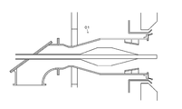
- FIG. 5 is an explanatory diagram of a comparative example.
- an experiment for confirming the effect of Example 1 was performed.
- the outer diameter D W1 of the first swirl vane 34c and the outer diameter D W2 of the second swirl vane 34d were the same.
- the outer diameter D W2 of the second swirl vane 34d is larger than the outer diameter D W1 of the first swirl vane 34c.
- Comparative Example 1 an experiment was conducted in the configuration of FIG. That is, the configuration of FIG. 5 does not have the enlarged portion 21b or the downstream portion 21c of the first embodiment. Further, in the configuration of FIG.
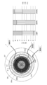
- FIG. 6 is an explanatory diagram of simulation results. 6, in Comparative Example 1, the ratio of fuel in the region 1 on the outer side in the radial direction is small, and the ratio of fuel in the region 2 in the middle in the radial direction is large. That is, the fuel was not concentrated on the outer peripheral side, and the fuel concentration effect was insufficient. On the other hand, in Experimental Example 1, the ratio of the fuel in the region 1 on the outer peripheral side was the highest in all of the regions 1 to 3, and the fuel was concentrated on the outer peripheral side. Further, in Experimental Example 2, a result in which the ratio of the fuel in the region 1 was larger than that in Experimental Example 1 was obtained.
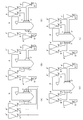
- FIG. 7 is an explanatory view of a boiler (combustion device) equipped with the solid fuel burner of the present invention
- FIG. 7(A) is a can front side and a can back side of the three-stage solid fuel burner before and after the can (boiler).
- FIGS. 7(C) and 7(E) are explanatory views of the case where the solid fuel burner of the present invention is used, in which biomass fuel is used in the uppermost stage behind the can. Is.
- FIG. 7 is an explanatory view of a boiler (combustion device) equipped with the solid fuel burner of the present invention
- FIG. 7(A) is a can front side and a can back side of the three-stage solid fuel burner before and after the can (boiler).
- the biomass fuel is supplied to the uppermost solid fuel burner 7 of the solid fuel burners 7.
- coal as an example of solid fuel is supplied to the solid fuel burners 7'in the middle and lower stages.
- the coal contained in the bunker 4' is pulverized by the mill 5'to become pulverized coal, which is supplied to the solid fuel burners 7'in the middle and lower stages.
- a plurality of solid fuel burners 7 are installed along the furnace width direction of the combustion device 1.
- the form of the solid fuel burner 7' is not necessarily the solid fuel burner of the present invention described above.
- the biomass fuel having a large particle size may fall to the furnace bottom without being ignited. If unignited biomass fuel accumulates at the bottom of the furnace, there is a problem in that maintenance must be performed more frequently and fuel is wasted.
- the biomass fuel is used only in the uppermost solid fuel burner 7. Therefore, even if the unburned biomass fuel is generated in the uppermost solid fuel burner 7, it is easily ignited and burned out in the middle and lower solid fuel burners 7'before falling to the furnace bottom. In particular, in the area where the solid fuel burners 7, 7'are installed in the boiler 6, the temperature tends to become higher as it goes upward.
- the existing combustion device 1 having three stages of solid fuel burners on the front side and the rear side of the can it is possible to change the biomass fuel to be used only by the uppermost stage solid fuel burner 7. Therefore, the existing combustion device 1 that uses only coal can be easily converted to the combustion device 1 that uses biomass fuel.
- the number of stages of the solid fuel burners 7 and 7′ is different before and after the can (or the same number of stages is provided, but one stage is paused). Also in (), it is possible to change the biomass fuel to be used only by the uppermost one solid fuel burner 7 on the front side or the rear side of the can.
- the configuration in which the solid fuel burners 7 and 7 ′ are provided in three stages in the vertical direction is illustrated, but the configuration is not limited to this. It is also possible to adopt a configuration of two stages or four or more stages. At this time, it is desirable that the solid fuel burner 7 that uses the biomass fuel is at the uppermost stage, but the present invention is not limited to this. It is also possible to have two or more stages, the top stage and the middle stage. Further, for example, as shown in FIGS. 7D and 7E, at the uppermost stage, one solid fuel burner 7 uses biomass fuel and the other solid fuel burner 7'uses pulverized coal. It is also possible to do so. That is, the solid fuel burner 7 using the biomass fuel and the solid fuel burner 7'using the pulverized coal may be opposed to each other.
- the present invention is not limited to the above embodiments, and various modifications can be made within the scope of the gist of the present invention described in the claims. It is possible.
- the shape of the support member 37 is not limited to a plate shape, and can be changed to any shape such as a wedge shape, a diamond shape, or a trapezoidal shape.
- the configuration of the two-stage combustion gas nozzles 26 and 27 having the secondary combustion gas nozzle 26 and the tertiary combustion gas nozzle 27 is illustrated, but the configuration is not limited to this, and the combustion gas nozzle may be one stage or three or more stages. It is also possible to do so.
- the fuel concentrator 34 a configuration having two first swirlers 34a and second swirlers 34b is illustrated, but the fuel concentrator 34 is not limited to this. It is possible to provide three or more or one. Even when the number of swirlers is one, the swirl is weakened in the flow path partitioning member 36, so that the mixed fluid after passing through the flow path partitioning member 36 is ejected in a state in which the swirl is weakened. Further, in consideration of the weakening of the swirl in the flow path partitioning member 36, it is possible to make the performance of the second swirler 34b for giving the reverse swirl lower than the performance of giving the swirl of the first swirl 34a. Is. That is, the outer diameter of the second swirl vane 34d can be shortened, the inclination angle can be reduced, the axial length can be shortened, and the like.
Landscapes
- Engineering & Computer Science (AREA)
- Chemical & Material Sciences (AREA)
- Combustion & Propulsion (AREA)
- Mechanical Engineering (AREA)
- General Engineering & Computer Science (AREA)
- Meat, Egg Or Seafood Products (AREA)
Abstract
Description
一般に微粉炭等を燃料とする固体燃料バーナでは、燃料搬送ガスと燃料粒子との混合流体に対して、燃料ノズル内でノズル内壁面に向かう速度成分を付与して燃料粒子がノズル内壁面沿いに濃縮するような燃料濃縮器(機構)を設けることが多い。
続いて、第二旋回器(7)で第一旋回器(6)とは逆向きの旋回を付与することで混合流体の旋回を弱める。
したがって、バーナの開口部、燃料ノズルの先端部に設置された保炎器(10)の周辺で固体燃料粒子が濃縮された状態が保たれ、バーナに供給される燃料濃度が低い低負荷時でも燃料粒子の着火性が高まり、火炎の安定性が向上する。
同時に、旋回が弱められた混合流体が開口部から噴出するので、混合流体が火炉内に過度に広がることなく、二次空気や三次空気等の燃焼用ガス(空気)との混合を緩やかにして窒素酸化物(NOx)生成の抑制が図られる。
結果的に、粒子の粗いバイオマス燃料は、微粉炭に比べて着火性が低くなっている。
よって、バーナで燃焼させる直前までは混合流体(燃料搬送気体)の流速を高く保つ必要がある。
このため、燃料ノズルの流路断面積を上流側、即ち粉砕装置から接続される燃料搬送系統(燃料搬送配管との接続部)側では小さく、下流側、即ち火炉開口部側では上流側よりも大きくして流速を低減することで、着火性を向上させることが考えられる。
ここで、特許文献3は、混合流体の燃料濃縮を図るための機構として、ベンチュリーと燃料ノズルの中心から離れる向きの速度成分を付与する燃料濃縮器とを備え、燃料ノズルの火炉側開口部の内径が、ベンチュリーの上流端の内径よりも大きく形成された固体燃料バーナを開示している。このような構成であれば、搬送系統内では混合流体の流速を高く保持しながら、燃料粒子をバーナで燃焼させる直前に流速を低減できるので、着火性の向上が図られる。
一方、特許文献3に記載の固体燃料バーナの燃料ノズル上流側、ミルからバーナに至る燃料搬送配管との接続部には、曲管部が設けられている。混合流体は、燃料搬送配管から曲管部を経て燃料ノズルの直管部へと連通する流路を流れることになる。
発明者らのシミュレーションモデル等による解析の結果、このような構成では、曲管部を通過した高速の流体は上面に衝突後、反射されるように下方に流れやすく、特にベンチュリーでノズル中心軸側に燃料を濃縮した後、紡錘状の燃料濃縮器により、燃料ノズルの中心から離れる向きの速度成分を付与すると、周方向の燃料粒子の偏りが生じ、燃料ノズル各部の長さの設定等によっては、燃料ノズルの上側の流体の流速が過度に遅くなりやすいことが判明した。そして、流速が過度に遅くなると、燃料の自重で燃料が径方向の中央部に向けて片寄りやすくなり、燃料ノズルの出口近傍では、上側の径方向外側において、燃料の濃度が低い領域が発生して、燃料の濃縮効果が下がる可能性があることがわかった。
請求項1に記載の発明の固体燃料バーナは、
固体燃料とその搬送気体の混合流体が流れ、火炉に向かって開口する燃料ノズルと、
前記燃料ノズルの外周側に配置され、燃焼用気体を噴出させる燃焼用ガスノズルと、
前記燃料ノズルの中心側に設けられ、前記燃料ノズルの中心から離れる向きの速度成分を前記混合流体に付与する燃料濃縮器とを備えた固体燃料バーナであって、
前記燃料濃縮器は、前記混合流体に旋回を与える複数の羽根を有し、各々の羽根が燃料ノズルの内側に全面固定されることなく前記燃料ノズルの内面から離れて配置されるものであって、前記混合流体の流れ方向の上流側に配置される第1の旋回器と、前記第1の旋回器に対して前記混合流体の流れ方向の下流側に配置され、前記複数の羽根の旋回方向が前記第1の旋回器とは逆方向である第2の旋回器と、を有し、
前記第2の旋回器に対して前記混合流体の流れ方向の下流側に、前記燃料ノズルの流路を流路断面における内側と外側とに区画する流路区画部材が設けられていること
を特徴とする。
前記第1の旋回器および前記第2の旋回器の外径は、前記流路区画部材の上流端の内径以下である、
ことを特徴とする。
前記流路区画部材は、上流端の内径が下流端の内径よりも大きい形状であることを特徴とする。
前記第2の旋回器の外径が、前記流路区画部材の上流端の内径よりも小さく、下流端の内径よりも大きいことを特徴とする。
固体燃料とその搬送気体の混合流体が流れ、火炉に向かって開口する燃料ノズルと、
前記燃料ノズルの外周側に配置され、燃焼用気体を噴出させる燃焼用ガスノズルと、
前記燃料ノズルの前記中心側に設けられ、前記燃料ノズルの中心から離れる向きの速度成分を前記混合流体に付与する燃料濃縮器とを備えた固体燃料バーナであって、
前記燃料濃縮器は、前記混合流体に旋回を与える複数の羽根を有し、各々の羽根が燃料ノズルの内側に全面固定されることなく前記燃料ノズルの内面から離れて配置されるものであって、前記混合流体の流れ方向の上流側に配置される第1の旋回器と、前記第1の旋回器に対して前記混合流体の流れ方向の下流側に配置され、前記複数の羽根の旋回方向が前記第1の旋回器とは逆方向である第2の旋回器と、を有し、
前記燃料ノズルの流路は、内径が、前記第1の旋回器の上流側では同一または単調増加の上流部と、前記上流部の下流側に連通して内径が徐々に拡大する拡管部と、前記拡管部の下流側に連通して内径が一定の下流部と、を有する、
ことを特徴とする。
前記第1の旋回器の少なくとも一部が前記燃料ノズル流路の上流部の範囲に位置し、
前記第2の旋回器の少なくとも一部が前記燃料ノズル流路の下流部の範囲に位置する
ことを特徴とする。
前記燃料ノズル流路の下流部の範囲に前記燃料ノズルの流路を、流路断面における内側と外側とに区画する流路区画部材
を備えたことを特徴とする。
前記流路区画部材は、上流端の内径が下流端の内径よりも大きい形状であって、
前記第2の旋回器の外径が、前記流路区画部材の上流端の内径よりも小さく、前記流路区画部材の下流端の内径よりも大きい
ことを特徴とする。
前記各旋回器の外径は、前記燃料ノズル流路の上流部の内径未満である
ことを特徴とする。
図1において、火力発電所等で使用される実施例1の燃焼システム(燃焼装置)1では、バイオマス燃料(固体燃料)がバンカ(燃料ホッパ)4に収容されている。バンカ4のバイオマス燃料は、ミル(粉砕機)5で粉砕される。粉砕された燃料は、ボイラ(火炉)6の固体燃料バーナ7に燃料配管8を通じて供給されて、燃焼される。なお、固体燃料バーナ7は、ボイラ6に複数設置されている。
空気予熱器10を通過した排ガスは、ガスガスヒータ(熱回収器)13を通過する際に熱が回収されて低温化する。
乾式集塵機14を通過した排ガスは、脱硫装置15に送られて脱硫される。
脱硫装置15を通過した排ガスは、湿式集塵機16で排ガス中の塵等が回収、除去される。
湿式集塵機16を通過した排ガスは、ガスガスヒータ(再加熱器)17で再加熱される。
ガスガスヒータ(再加熱器)17を通過した排ガスは、煙突18から大気に排気される。
なお、ミル5自体の構成は、従来公知の種々の構成を使用可能であり、例えば、特開2010-242999号公報等に記載されているので詳細な説明は省略する。
図3は図2の矢印III方向から見た図である。
図2、図3において、実施例1の固体燃料バーナ7は、搬送気体が流れる燃料ノズル21を有する。燃料ノズル21の下流端の開口は、ボイラ6の火炉22の壁面(火炉壁、水管壁)23に設けられている。燃料ノズル21は、搬送気体の流れ方向の上流端部に曲管部の一例としてのエルボ20が形成されている。エルボ20では、混合流体の流れ方向が略90°曲げられるように屈曲している。エルボ20の上流端には、燃料配管8が接続される。燃料ノズル21は中空の筒状に形成されており、燃料ノズル21の内部には、固体燃料(粉砕されたバイオマス燃料)と搬送気体とからなる混合流体が流れる流路24が形成されている。
図2、図3において、燃料ノズル21の流路断面の中心部には、点火バーナ(オイルガン)32が貫通して配置されている。点火バーナ32は、燃料ノズル21の衝突板フランジ20aに支持された衝突板32aに貫通した状態で支持されている。
直管部21aの下流側には、下流側に行くにつれて内径(すなわち断面積)が拡大する拡大部21bが接続されている。拡大部21bの下流側には、下流端に向けて断面積が同一な直管状の下流部21cが接続されている。
実施例1では、拡大部21bの内壁が、直管部21aの延長線に対してなす角θ1は、10°~15°に設定されている。θ1が10°未満の場合、燃料ノズル21の軸方向の長さが長くなり、θ1が15°を超える場合、混合流の流れに剥離が発生して、流れに澱みが発生して澱んだ部分に燃料が溜まりやすくなる問題があるため、θ1は10°~15°が好ましい。
ノズル全体を通じて、バイオマス燃料のような粒子の粗い燃料を使用しても旋回を過度に強める必要が無く、圧力損失や燃料粒子の旋回器(34a,34b)への付着をできるように構成されていれば良い。
第1の旋回器34aは、点火バーナ32を軸とする螺旋状に形成された複数枚の第1の旋回羽根34cを有する。また、第2の旋回器34bは、第1の旋回羽根34cとは逆方向(逆巻きの螺旋状)に傾斜する第2の旋回羽根34dを有する。各旋回羽根34c,34dは、燃料ノズル21の内面に固定されておらず、旋回羽根34c,34dの外周端は燃料ノズル21の内面から離間して設置されている。
第1の旋回器34aは、その羽根34cが長手方向(の少なくとも一部)において上流部(直管部21a)にかかっていることが望ましい。これにより、上流部21aを流れてきた混合流体に対して効率よく径方向外向き(ノズル内壁向き)の速度成分を与えることができる。
また、第2の旋回器34bについては、その羽根34dが長手方向(の少なくとも一部)において下流部21c(下流側の直管部)にかかっていることが望ましい。即ち、その羽根の長手方向(燃料ノズル21の軸方向)下流側端部が燃料ノズル21の下流部21c(下流側の直管部)側に位置するように設けられることが望ましい。これにより、第2の旋回器34bとして圧力損失を抑制しつつ、旋回の打ち消し効果が十分なものを第1の旋回器34aとの適切な間隔を空けて配置できる。
第2の旋回羽根34dの外径DW2は、第1の旋回羽根34cの外径DW1以上の大きさに形成されている(すなわち、DW2≧DW1)。また、実施例1では、外径DW2<内径D1に形成されている。さらに、第2の旋回羽根34dの外径DW2は、下流部21cの内径D2に対して、一例として65%に設定されており、55%~80%に設定することが好ましい。55%未満では、逆旋回で旋回を打ち消す効果が低くなる。また、80%を超えると、メンテナンス時に点火バーナ32を燃料ノズル21から引き抜くことが困難になる。したがって、点火バーナ32を引き抜かない構成の場合は、外径DW2が内径D2の80%を超えたり、外径DW2≧内径D1としたりすることも可能である。
(1)L2=L4
(2)L5-L4=0.7×D2
(3)L5-L1=0.1×D2
(2)については、0.7×D2~1.3×D2が好ましいことが燃焼試験で確認された。0.7未満になると、第1の旋回器34aの旋回で燃料が外径側に十分に到達する前に、第2の旋回器34bで旋回が打ち消されることとなり、燃料の濃縮効果が低減する。1.3を超えると、旋回の打ち消しが遅くなって、燃料ノズル21の下流端で旋回が強く残り、NOxが増える問題があった。
第1の旋回器34aは、その羽根34cが長手方向(の少なくとも一部)において上流部(直管部21a)にかかっており、上流部21aを流れてきた混合流体に対して効率よく径方向外向き(ノズル内壁向き)の速度成分を与えることができる。
図2、図3において、燃料濃縮器34の下流側には、流路区画部材36が配置されている。流路区画部材36は、支持部材37により燃料ノズル21の内面に支持されている。実施例1の流路区画部材36は、上流端S1から下流端S2に向かうに連れて内径が縮小する部分円錐状(コニカル形状)に形成されている。したがって、流路区画部材36は、流路24を外側流路24aと内側流路24bとに区画する。
図3、図4において、支持部材37は、径方向に沿って延びる板状に形成されている。支持部材37は、周方向に対して間隔をあけて複数配置されている。図3において、実施例1では、支持部材37は、保炎器31の内周側突起31aどうしの間に対応する位置に配置されている。
したがって、流路区画部材36を有しない特許文献1に記載の構成に比べて、着火性の悪いバイオマス燃料を粉砕した固体燃料粒子を使用する場合でも、燃料の濃縮効果を確保することができる。
なお、流路区画部材36が軸方向に対して傾斜する傾斜角θ2を、10°~15°とすることが好ましい。なお、θ2を10°~15°にすることが好ましい理由は、θ1の場合と同様である。
なお、1.0×D2を超えると、流路区画部材36の下流端S2が、各位置fsおよび火炉壁面開口部から離れすぎる。よって、流路区画部材36での流速低減後の区間が長くなる。流速低減後の区間が長くなると、燃料粒子が燃料ノズル21の壁面に付着堆積する可能性が高くなったり、燃料ノズル21が長大化して固体燃料バーナ7が大型化するといった問題がある。
したがって、燃料濃縮後は断面積が減少せず、流速が増大と減少を繰り返さないため、燃料の堆積、滞留が低減され、濃縮されたまま減速されて火炉6に向けて供給される。すなわち、燃料ノズル21の配管内では、粒径の大きな燃料粒子の滞留を招かぬように高流速で搬送しつつ、火炉6開口部側では上流側よりも流路断面積が大きく流速が低減されることで、着火性と火炎の安定性が向上する。
ノズル軸方向で見た支持部材の断面形状は、流れを妨げないものであれば特に限定されず、流線形の翼状(図4(C)参照)、ひし形(図4(D))等でも良い。翼状、ひし形状の場合、流れ方向に沿って、流路が一旦縮小するため、燃料粒子の濃縮がさらに増強され、着火・保炎性が向上する効果がある。
また、実施例1の支持部材37は、保炎器31の内周側突起31aと重ならない位置に配置されており、重なる場合に比べて、混合気体の流れの抵抗が低減されている。
一方、ノズル軸方向で見た支持部材37の断面形状が流線形の翼状、ひし形等流れ方向に沿って、流路が一旦縮小する例(図4(C),(D)に示される例)では、流路が一旦縮小して燃料粒子の濃縮した(即ち分布が生じた)領域の下流に保炎器の突起が位置するため、着火・保炎性が向上する効果がある。
図5は比較例の説明図である。
次に、実施例1の効果を確認する実験(コンピュータシミュレーション)を行った。実験例1では、実施例1の構成において、第1の旋回羽根34cの外径DW1と第2の旋回羽根34dの外径DW2を同一とした。また、実験例2では、第2の旋回羽根34dの外径DW2が、第1の旋回羽根34cの外径DW1よりも大きい場合とした。また、比較例1では、図5の構成において実験を行った。すなわち、図5の構成では、実施例1の拡大部21bや下流部21cを有しない。また、図5の構成では、燃料濃縮器として、旋回羽根ではなく、燃料ノズルの断面積が減少して燃料を径方向の内側に濃縮した後、点火バーナに支持された下流側に行くほど径が大きくなる部材で燃料を径方向外側に移動させることで、径方向の外側に燃料を濃縮するベンチュリ01を有する。
シミュレーションでは、燃料ノズル21の下流端において、径方向の燃料の分布(割合)を測定した。結果を図6に示す。
図6において、比較例1では、径方向の外側の領域1の燃料の割合が少なく、径方向の中間の領域2の燃料の割合が多い結果となった。すなわち、外周側に燃料が濃縮されておらず、燃料の濃縮効果が不十分であった。
一方、実験例1では、外周側の領域1の燃料の割合が、領域1~領域3の全ての領域の中で最も多く、外周側に燃料が濃縮されていた。また、実験例2では、実験例1よりもさらに領域1の燃料の割合が多い結果が得られた。
図7(A)に示す形態では、固体燃料バーナ7のうち、最上段の固体燃料バーナ7には、バイオマス燃料が供給される。一方、中段と下段の固体燃料バーナ7′には、固体燃料の一例としての石炭が供給される。石炭は、バンカ4′に収容されたものがミル5′で粉砕されて微粉炭となり、中段と下段の固体燃料バーナ7′に供給される。なお、各段において、固体燃料バーナ7は、燃焼装置1の炉幅方向に沿って複数設置されている。
固体燃料バーナ7′の形態は、必ずしも上述した本発明の固体燃料バーナでなくても良い。
これらに対して、図7(A)に示す形態では、最上段の固体燃料バーナ7のみでバイオマス燃料が使用される。したがって、最上段の固体燃料バーナ7で未着火のバイオマス燃料が発生しても、炉底に落下するまでの間に、中段と下段の固体燃料バーナ7′で着火されて燃え尽きやすい。特に、ボイラ6において、固体燃料バーナ7,7′が設置されている領域では、上方ほど高温になりやすい。したがって、最上段の固体燃料バーナ7でバイオマス燃料を使用すれば、下段の固体燃料バーナでバイオマス燃料を使用する場合に比べて、未着火のバイオマス燃料が発生しにくい。よって、図7(A)に示す形態では、未着火のバイオマス燃料が炉底に落下しにくく、燃料の無駄等を抑制できる。
さらに、図7(B)、図7(C)に示すように、固体燃料バーナ7,7′の段数が缶前後で異なる構成(あるいは、同数段備えているが、1つ休止させている構成)においても、缶前側または缶後側の最上段の1つの固体燃料バーナ7のみでバイオマス燃料を使用するように変更することも可能である。
このとき、バイオマス燃料を使用する固体燃料バーナ7は、最上段とすることが望ましいが、これに限定されない。最上段と中段の2段以上とすることも可能である。
また、例えば、図7(D)、図7(E)のように最上段において、一方の固体燃料バーナ7ではバイオマス燃料を使用し、他方の固体燃料バーナ7′では微粉炭を使用する構成とすることも可能である。すなわち、バイオマス燃料を使用する固体燃料バーナ7と、微粉炭を使用する固体燃料バーナ7′とを対向させる構成とすることも可能である。
例えば、支持部材37の形状は、板状に限定されず、楔状やひし形状、台形状等任意の形状に変更可能である。
また、2次燃焼用ガスノズル26と3次燃焼用ガスノズル27を有する2段の燃焼用ガスノズル26,27の構成を例示したが、これに限定されず、燃焼用ガスノズルは1段または3段以上とすることも可能である。
21…燃料ノズル、
22…火炉、
24…混合流体の流路、
24a…外側流路、
26,27…燃焼用ガスノズル、
34…燃料濃縮器、
34c,34d…羽根
36…流路区画部材。
Claims (9)
- 固体燃料とその搬送気体の混合流体が流れ、火炉に向かって開口する燃料ノズルと、
前記燃料ノズルの外周側に配置され、燃焼用気体を噴出させる燃焼用ガスノズルと、
前記燃料ノズルの中心側に設けられ、前記燃料ノズルの中心から離れる向きの速度成分を前記混合流体に付与する燃料濃縮器とを備えた固体燃料バーナであって、
前記燃料濃縮器は、前記混合流体に旋回を与える複数の羽根を有し、各々の羽根が燃料ノズルの内側に全面固定されることなく前記燃料ノズルの内面から離れて配置されるものであって、前記混合流体の流れ方向の上流側に配置される第1の旋回器と、前記第1の旋回器に対して前記混合流体の流れ方向の下流側に配置され、前記複数の羽根の旋回方向が前記第1の旋回器とは逆方向である第2の旋回器と、を有し、
前記第2の旋回器に対して前記混合流体の流れ方向の下流側に、前記燃料ノズルの流路を流路断面における内側と外側とに区画する流路区画部材が設けられていること
を特徴とする固体燃料バーナ。 - 前記第1の旋回器および前記第2の旋回器の外径は、前記流路区画部材の上流端の内径以下である、
ことを特徴とする請求項1に記載の固体燃料バーナ。 - 前記流路区画部材は、上流端の内径が下流端の内径よりも大きい形状であることを特徴とする請求項1に記載の固体燃料バーナ。
- 前記第2の旋回器の外径が、前記流路区画部材の上流端の内径よりも小さく、下流端の内径よりも大きいことを特徴とする請求項3に記載の固体燃料バーナ。
- 固体燃料とその搬送気体の混合流体が流れ、火炉に向かって開口する燃料ノズルと、
前記燃料ノズルの外周側に配置され、燃焼用気体を噴出させる燃焼用ガスノズルと、
前記燃料ノズルの前記中心側に設けられ、前記燃料ノズルの中心から離れる向きの速度成分を前記混合流体に付与する燃料濃縮器とを備えた固体燃料バーナであって、
前記燃料濃縮器は、前記混合流体に旋回を与える複数の羽根を有し、各々の羽根が燃料ノズルの内側に全面固定されることなく前記燃料ノズルの内面から離れて配置されるものであって、前記混合流体の流れ方向の上流側に配置される第1の旋回器と、前記第1の旋回器に対して前記混合流体の流れ方向の下流側に配置され、前記複数の羽根の旋回方向が前記第1の旋回器とは逆方向である第2の旋回器と、を有し、
前記燃料ノズルの流路は、内径が、前記第1の旋回器の上流側では同一または単調増加の上流部と、前記上流部の下流側に連通して内径が徐々に拡大する拡管部と、前記拡管部の下流側に連通して内径が一定の下流部と、を有する、
ことを特徴とする固体燃料バーナ。 - 前記第1の旋回器の少なくとも一部が前記燃料ノズル流路の上流部の範囲に位置し、
前記第2の旋回器の少なくとも一部が前記燃料ノズル流路の下流部の範囲に位置する
ことを特徴とする請求項5に記載の固体燃料バーナ。 - 前記燃料ノズル流路の下流部の範囲に前記燃料ノズルの流路を、流路断面における内側と外側とに区画する流路区画部材
を備えたことを特徴とする請求項6に記載の固体燃料バーナ。 - 前記流路区画部材は、上流端の内径が下流端の内径よりも大きい形状であって、
前記第2の旋回器の外径が、前記流路区画部材の上流端の内径よりも小さく、前記流路区画部材の下流端の内径よりも大きい
ことを特徴とする請求項7に記載の固体燃料バーナ。 - 前記各旋回器の外径は、前記燃料ノズル流路の上流部の内径未満である
ことを特徴とする請求項1ないし8のいずれかに記載の固体燃料バーナ。
Priority Applications (5)
| Application Number | Priority Date | Filing Date | Title |
|---|---|---|---|
| AU2020210392A AU2020210392B2 (en) | 2019-01-25 | 2020-01-22 | Solid fuel burner |
| KR1020217025984A KR102603016B1 (ko) | 2019-01-25 | 2020-01-22 | 고체 연료 버너 |
| MYPI2021004139A MY208352A (en) | 2019-01-25 | 2020-01-22 | Solid fuel burner |
| PH1/2021/551765A PH12021551765A1 (en) | 2019-01-25 | 2020-01-22 | Solid fuel burner |
| JP2020568185A JP7413284B2 (ja) | 2019-01-25 | 2020-01-22 | 固体燃料バーナ |
Applications Claiming Priority (2)
| Application Number | Priority Date | Filing Date | Title |
|---|---|---|---|
| PCT/JP2019/002549 WO2020152867A1 (ja) | 2019-01-25 | 2019-01-25 | 固体燃料バーナおよび燃焼装置 |
| JPPCT/JP2019/002549 | 2019-01-25 |
Publications (1)
| Publication Number | Publication Date |
|---|---|
| WO2020153404A1 true WO2020153404A1 (ja) | 2020-07-30 |
Family
ID=71736216
Family Applications (2)
| Application Number | Title | Priority Date | Filing Date |
|---|---|---|---|
| PCT/JP2019/002549 Ceased WO2020152867A1 (ja) | 2019-01-25 | 2019-01-25 | 固体燃料バーナおよび燃焼装置 |
| PCT/JP2020/002138 Ceased WO2020153404A1 (ja) | 2019-01-25 | 2020-01-22 | 固体燃料バーナ |
Family Applications Before (1)
| Application Number | Title | Priority Date | Filing Date |
|---|---|---|---|
| PCT/JP2019/002549 Ceased WO2020152867A1 (ja) | 2019-01-25 | 2019-01-25 | 固体燃料バーナおよび燃焼装置 |
Country Status (7)
| Country | Link |
|---|---|
| JP (1) | JP7413284B2 (ja) |
| KR (1) | KR102603016B1 (ja) |
| AU (1) | AU2020210392B2 (ja) |
| MY (1) | MY208352A (ja) |
| PH (1) | PH12021551765A1 (ja) |
| TW (1) | TWI748336B (ja) |
| WO (2) | WO2020152867A1 (ja) |
Cited By (1)
| Publication number | Priority date | Publication date | Assignee | Title |
|---|---|---|---|---|
| WO2024262605A1 (ja) * | 2023-06-21 | 2024-12-26 | 三菱重工業株式会社 | バーナ及びこれを備えたボイラ並びにバーナの運転方法 |
Families Citing this family (1)
| Publication number | Priority date | Publication date | Assignee | Title |
|---|---|---|---|---|
| CN116772199B (zh) * | 2023-06-25 | 2024-04-05 | 北京天地融创科技股份有限公司 | 一种稳燃器 |
Citations (8)
| Publication number | Priority date | Publication date | Assignee | Title |
|---|---|---|---|---|
| JPS6231047B2 (ja) * | 1977-04-25 | 1987-07-06 | Tokyo Shibaura Electric Co | |
| JPH0424404A (ja) * | 1990-05-21 | 1992-01-28 | Babcock Hitachi Kk | 微粉炭バーナ |
| JPH09112820A (ja) * | 1995-10-17 | 1997-05-02 | Babcock Hitachi Kk | 微粉炭バーナ |
| JPH1038216A (ja) * | 1996-07-22 | 1998-02-13 | Ishikawajima Harima Heavy Ind Co Ltd | 微粉炭バーナ |
| JP2003240227A (ja) * | 2002-02-14 | 2003-08-27 | Hitachi Ltd | 固体燃料バーナと固体燃料バーナの燃焼方法 |
| JP2005024136A (ja) * | 2003-06-30 | 2005-01-27 | Babcock Hitachi Kk | 燃焼装置 |
| WO2012042910A1 (ja) * | 2010-09-30 | 2012-04-05 | バブコック日立株式会社 | 燃焼システム及びその運転方法 |
| WO2018207559A1 (ja) * | 2017-05-11 | 2018-11-15 | 三菱日立パワーシステムズ株式会社 | 固体燃料バーナおよび燃焼装置 |
Family Cites Families (6)
| Publication number | Priority date | Publication date | Assignee | Title |
|---|---|---|---|---|
| JPS4919844B1 (ja) | 1969-04-15 | 1974-05-21 | ||
| JPS6231047U (ja) | 1985-08-10 | 1987-02-24 | ||
| JP2010242999A (ja) | 2009-04-02 | 2010-10-28 | Babcock Hitachi Kk | 木質バイオマス直接粉砕燃焼方法と装置とボイラシステム |
| BR112016008410B1 (pt) * | 2013-10-17 | 2021-11-16 | Hatch Pty Ltd | Aparelho de dispersão e método para a modificação do curso de deslocamento do material em partículas que flui através de uma passagem de um aparelho de dispersão |
| JP6231047B2 (ja) * | 2015-06-30 | 2017-11-15 | 三菱日立パワーシステムズ株式会社 | 固体燃料バーナ |
| CN106907709B (zh) * | 2017-02-23 | 2019-08-16 | 中国科学院工程热物理研究所 | 一种旋流数和湍流度可调的喷嘴、喷嘴阵列和燃烧器 |
-
2019
- 2019-01-25 WO PCT/JP2019/002549 patent/WO2020152867A1/ja not_active Ceased
-
2020
- 2020-01-22 PH PH1/2021/551765A patent/PH12021551765A1/en unknown
- 2020-01-22 TW TW109102656A patent/TWI748336B/zh active
- 2020-01-22 MY MYPI2021004139A patent/MY208352A/en unknown
- 2020-01-22 KR KR1020217025984A patent/KR102603016B1/ko active Active
- 2020-01-22 WO PCT/JP2020/002138 patent/WO2020153404A1/ja not_active Ceased
- 2020-01-22 AU AU2020210392A patent/AU2020210392B2/en active Active
- 2020-01-22 JP JP2020568185A patent/JP7413284B2/ja active Active
Patent Citations (8)
| Publication number | Priority date | Publication date | Assignee | Title |
|---|---|---|---|---|
| JPS6231047B2 (ja) * | 1977-04-25 | 1987-07-06 | Tokyo Shibaura Electric Co | |
| JPH0424404A (ja) * | 1990-05-21 | 1992-01-28 | Babcock Hitachi Kk | 微粉炭バーナ |
| JPH09112820A (ja) * | 1995-10-17 | 1997-05-02 | Babcock Hitachi Kk | 微粉炭バーナ |
| JPH1038216A (ja) * | 1996-07-22 | 1998-02-13 | Ishikawajima Harima Heavy Ind Co Ltd | 微粉炭バーナ |
| JP2003240227A (ja) * | 2002-02-14 | 2003-08-27 | Hitachi Ltd | 固体燃料バーナと固体燃料バーナの燃焼方法 |
| JP2005024136A (ja) * | 2003-06-30 | 2005-01-27 | Babcock Hitachi Kk | 燃焼装置 |
| WO2012042910A1 (ja) * | 2010-09-30 | 2012-04-05 | バブコック日立株式会社 | 燃焼システム及びその運転方法 |
| WO2018207559A1 (ja) * | 2017-05-11 | 2018-11-15 | 三菱日立パワーシステムズ株式会社 | 固体燃料バーナおよび燃焼装置 |
Cited By (2)
| Publication number | Priority date | Publication date | Assignee | Title |
|---|---|---|---|---|
| WO2024262605A1 (ja) * | 2023-06-21 | 2024-12-26 | 三菱重工業株式会社 | バーナ及びこれを備えたボイラ並びにバーナの運転方法 |
| TWI897492B (zh) * | 2023-06-21 | 2025-09-11 | 日商三菱重工業股份有限公司 | 燃燒器及具備其之鍋爐,以及燃燒器之運轉方法 |
Also Published As
| Publication number | Publication date |
|---|---|
| TW202033912A (zh) | 2020-09-16 |
| AU2020210392A1 (en) | 2021-08-05 |
| AU2020210392B2 (en) | 2023-06-01 |
| JPWO2020153404A1 (ja) | 2021-11-18 |
| WO2020152867A1 (ja) | 2020-07-30 |
| KR20210113370A (ko) | 2021-09-15 |
| TWI748336B (zh) | 2021-12-01 |
| JP7413284B2 (ja) | 2024-01-15 |
| KR102603016B1 (ko) | 2023-11-15 |
| PH12021551765A1 (en) | 2022-05-23 |
| MY208352A (en) | 2025-05-01 |
Similar Documents
| Publication | Publication Date | Title |
|---|---|---|
| JP5897363B2 (ja) | 微粉炭バイオマス混焼バーナ | |
| JP5867742B2 (ja) | 固体燃料バーナを備えた燃焼装置 | |
| JP4896143B2 (ja) | バーナ、バーナを備えた燃焼装置及びボイラ | |
| KR101486690B1 (ko) | 연소 버너, 고체 연료 연소 버너 및 고체 연료 연소 보일러, 보일러 및 보일러의 운전 방법 | |
| JP2009079794A (ja) | 固体燃料バーナ、固体燃料バーナを用いた燃焼装置とその運転方法 | |
| CN1230249A (zh) | 粉状固体燃料喷嘴头 | |
| CN103175200A (zh) | 生物质专烧燃烧器、生物质混烧锅炉和生物质燃料燃烧方法 | |
| JP7413284B2 (ja) | 固体燃料バーナ | |
| KR102126663B1 (ko) | 배기 가스 처리 장치 | |
| JP2010270993A (ja) | 燃料バーナ及び旋回燃焼ボイラ | |
| JP3924089B2 (ja) | 微粉炭バーナ及び微粉炭バーナを用いた燃焼装置 | |
| CN112781033B (zh) | 偏置煤粉燃烧器和燃烧系统 | |
| US5526758A (en) | Distribution cone for pulverized coal burners | |
| JP2005024136A (ja) | 燃焼装置 | |
| JPH04214102A (ja) | 微粉炭ボイラ及び微粉炭バーナ | |
| TWI691679B (zh) | 固體燃料噴燃器及燃燒裝置 | |
| JPH08200616A (ja) | 微粉状燃料燃焼バーナ | |
| JP6785046B2 (ja) | 排気ダクト及びボイラ並びに固体粒子の除去方法 | |
| JPH11148610A (ja) | 固体燃料燃焼用バーナと固体燃料用燃焼装置 | |
| WO2022024552A1 (ja) | サイクロンバーナ、サイクロンバーナユニット、ノズルユニット、およびサイクロンバーナの改造方法 | |
| JPH08285231A (ja) | 低NOx微粉炭バーナと微粉炭燃焼装置 | |
| JP6804318B2 (ja) | 燃焼バーナ及びこれを備えたボイラ | |
| WO2023127121A1 (ja) | サイクロンバーナ、サイクロンバーナユニット、及びサイクロンバーナの改造方法 | |
| KR20200037254A (ko) | 스팀 발생 장치용 석탄 노즐 조립체 |
Legal Events
| Date | Code | Title | Description |
|---|---|---|---|
| 121 | Ep: the epo has been informed by wipo that ep was designated in this application |
Ref document number: 20745003 Country of ref document: EP Kind code of ref document: A1 |
|
| ENP | Entry into the national phase |
Ref document number: 2020568185 Country of ref document: JP Kind code of ref document: A |
|
| NENP | Non-entry into the national phase |
Ref country code: DE |
|
| ENP | Entry into the national phase |
Ref document number: 2020210392 Country of ref document: AU Date of ref document: 20200122 Kind code of ref document: A |
|
| ENP | Entry into the national phase |
Ref document number: 20217025984 Country of ref document: KR Kind code of ref document: A |
|
| 122 | Ep: pct application non-entry in european phase |
Ref document number: 20745003 Country of ref document: EP Kind code of ref document: A1 |