WO2020153361A1 - 鋼材及び部品 - Google Patents
鋼材及び部品 Download PDFInfo
- Publication number
- WO2020153361A1 WO2020153361A1 PCT/JP2020/001966 JP2020001966W WO2020153361A1 WO 2020153361 A1 WO2020153361 A1 WO 2020153361A1 JP 2020001966 W JP2020001966 W JP 2020001966W WO 2020153361 A1 WO2020153361 A1 WO 2020153361A1
- Authority
- WO
- WIPO (PCT)
- Prior art keywords
- steel material
- less
- induction
- content
- fatigue strength
- Prior art date
- Legal status (The legal status is an assumption and is not a legal conclusion. Google has not performed a legal analysis and makes no representation as to the accuracy of the status listed.)
- Ceased
Links
Images


Classifications
-
- C—CHEMISTRY; METALLURGY
- C21—METALLURGY OF IRON
- C21D—MODIFYING THE PHYSICAL STRUCTURE OF FERROUS METALS; GENERAL DEVICES FOR HEAT TREATMENT OF FERROUS OR NON-FERROUS METALS OR ALLOYS; MAKING METAL MALLEABLE, e.g. BY DECARBURISATION OR TEMPERING
- C21D9/00—Heat treatment, e.g. annealing, hardening, quenching or tempering, adapted for particular articles; Furnaces therefor
- C21D9/32—Heat treatment, e.g. annealing, hardening, quenching or tempering, adapted for particular articles; Furnaces therefor for gear wheels, worm wheels, or the like
-
- C—CHEMISTRY; METALLURGY
- C21—METALLURGY OF IRON
- C21D—MODIFYING THE PHYSICAL STRUCTURE OF FERROUS METALS; GENERAL DEVICES FOR HEAT TREATMENT OF FERROUS OR NON-FERROUS METALS OR ALLOYS; MAKING METAL MALLEABLE, e.g. BY DECARBURISATION OR TEMPERING
- C21D6/00—Heat treatment of ferrous alloys
- C21D6/004—Heat treatment of ferrous alloys containing Cr and Ni
-
- C—CHEMISTRY; METALLURGY
- C21—METALLURGY OF IRON
- C21D—MODIFYING THE PHYSICAL STRUCTURE OF FERROUS METALS; GENERAL DEVICES FOR HEAT TREATMENT OF FERROUS OR NON-FERROUS METALS OR ALLOYS; MAKING METAL MALLEABLE, e.g. BY DECARBURISATION OR TEMPERING
- C21D6/00—Heat treatment of ferrous alloys
- C21D6/005—Heat treatment of ferrous alloys containing Mn
-
- C—CHEMISTRY; METALLURGY
- C21—METALLURGY OF IRON
- C21D—MODIFYING THE PHYSICAL STRUCTURE OF FERROUS METALS; GENERAL DEVICES FOR HEAT TREATMENT OF FERROUS OR NON-FERROUS METALS OR ALLOYS; MAKING METAL MALLEABLE, e.g. BY DECARBURISATION OR TEMPERING
- C21D6/00—Heat treatment of ferrous alloys
- C21D6/008—Heat treatment of ferrous alloys containing Si
-
- C—CHEMISTRY; METALLURGY
- C21—METALLURGY OF IRON
- C21D—MODIFYING THE PHYSICAL STRUCTURE OF FERROUS METALS; GENERAL DEVICES FOR HEAT TREATMENT OF FERROUS OR NON-FERROUS METALS OR ALLOYS; MAKING METAL MALLEABLE, e.g. BY DECARBURISATION OR TEMPERING
- C21D8/00—Modifying the physical properties of ferrous metals or ferrous alloys by deformation combined with, or followed by, heat treatment
-
- C—CHEMISTRY; METALLURGY
- C21—METALLURGY OF IRON
- C21D—MODIFYING THE PHYSICAL STRUCTURE OF FERROUS METALS; GENERAL DEVICES FOR HEAT TREATMENT OF FERROUS OR NON-FERROUS METALS OR ALLOYS; MAKING METAL MALLEABLE, e.g. BY DECARBURISATION OR TEMPERING
- C21D8/00—Modifying the physical properties of ferrous metals or ferrous alloys by deformation combined with, or followed by, heat treatment
- C21D8/06—Modifying the physical properties of ferrous metals or ferrous alloys by deformation combined with, or followed by, heat treatment during manufacturing of rods or wires
-
- C—CHEMISTRY; METALLURGY
- C22—METALLURGY; FERROUS OR NON-FERROUS ALLOYS; TREATMENT OF ALLOYS OR NON-FERROUS METALS
- C22C—ALLOYS
- C22C38/00—Ferrous alloys, e.g. steel alloys
-
- C—CHEMISTRY; METALLURGY
- C22—METALLURGY; FERROUS OR NON-FERROUS ALLOYS; TREATMENT OF ALLOYS OR NON-FERROUS METALS
- C22C—ALLOYS
- C22C38/00—Ferrous alloys, e.g. steel alloys
- C22C38/001—Ferrous alloys, e.g. steel alloys containing N
-
- C—CHEMISTRY; METALLURGY
- C22—METALLURGY; FERROUS OR NON-FERROUS ALLOYS; TREATMENT OF ALLOYS OR NON-FERROUS METALS
- C22C—ALLOYS
- C22C38/00—Ferrous alloys, e.g. steel alloys
- C22C38/002—Ferrous alloys, e.g. steel alloys containing In, Mg, or other elements not provided for in one single group C22C38/001 - C22C38/60
-
- C—CHEMISTRY; METALLURGY
- C22—METALLURGY; FERROUS OR NON-FERROUS ALLOYS; TREATMENT OF ALLOYS OR NON-FERROUS METALS
- C22C—ALLOYS
- C22C38/00—Ferrous alloys, e.g. steel alloys
- C22C38/005—Ferrous alloys, e.g. steel alloys containing rare earths, i.e. Sc, Y, Lanthanides
-
- C—CHEMISTRY; METALLURGY
- C22—METALLURGY; FERROUS OR NON-FERROUS ALLOYS; TREATMENT OF ALLOYS OR NON-FERROUS METALS
- C22C—ALLOYS
- C22C38/00—Ferrous alloys, e.g. steel alloys
- C22C38/02—Ferrous alloys, e.g. steel alloys containing silicon
-
- C—CHEMISTRY; METALLURGY
- C22—METALLURGY; FERROUS OR NON-FERROUS ALLOYS; TREATMENT OF ALLOYS OR NON-FERROUS METALS
- C22C—ALLOYS
- C22C38/00—Ferrous alloys, e.g. steel alloys
- C22C38/04—Ferrous alloys, e.g. steel alloys containing manganese
-
- C—CHEMISTRY; METALLURGY
- C22—METALLURGY; FERROUS OR NON-FERROUS ALLOYS; TREATMENT OF ALLOYS OR NON-FERROUS METALS
- C22C—ALLOYS
- C22C38/00—Ferrous alloys, e.g. steel alloys
- C22C38/06—Ferrous alloys, e.g. steel alloys containing aluminium
-
- C—CHEMISTRY; METALLURGY
- C22—METALLURGY; FERROUS OR NON-FERROUS ALLOYS; TREATMENT OF ALLOYS OR NON-FERROUS METALS
- C22C—ALLOYS
- C22C38/00—Ferrous alloys, e.g. steel alloys
- C22C38/12—Ferrous alloys, e.g. steel alloys containing tungsten, tantalum, molybdenum, vanadium, or niobium
-
- C—CHEMISTRY; METALLURGY
- C22—METALLURGY; FERROUS OR NON-FERROUS ALLOYS; TREATMENT OF ALLOYS OR NON-FERROUS METALS
- C22C—ALLOYS
- C22C38/00—Ferrous alloys, e.g. steel alloys
- C22C38/16—Ferrous alloys, e.g. steel alloys containing copper
-
- C—CHEMISTRY; METALLURGY
- C22—METALLURGY; FERROUS OR NON-FERROUS ALLOYS; TREATMENT OF ALLOYS OR NON-FERROUS METALS
- C22C—ALLOYS
- C22C38/00—Ferrous alloys, e.g. steel alloys
- C22C38/18—Ferrous alloys, e.g. steel alloys containing chromium
- C22C38/28—Ferrous alloys, e.g. steel alloys containing chromium with titanium or zirconium
-
- C—CHEMISTRY; METALLURGY
- C22—METALLURGY; FERROUS OR NON-FERROUS ALLOYS; TREATMENT OF ALLOYS OR NON-FERROUS METALS
- C22C—ALLOYS
- C22C38/00—Ferrous alloys, e.g. steel alloys
- C22C38/18—Ferrous alloys, e.g. steel alloys containing chromium
- C22C38/32—Ferrous alloys, e.g. steel alloys containing chromium with boron
-
- C—CHEMISTRY; METALLURGY
- C22—METALLURGY; FERROUS OR NON-FERROUS ALLOYS; TREATMENT OF ALLOYS OR NON-FERROUS METALS
- C22C—ALLOYS
- C22C38/00—Ferrous alloys, e.g. steel alloys
- C22C38/18—Ferrous alloys, e.g. steel alloys containing chromium
- C22C38/40—Ferrous alloys, e.g. steel alloys containing chromium with nickel
-
- C—CHEMISTRY; METALLURGY
- C22—METALLURGY; FERROUS OR NON-FERROUS ALLOYS; TREATMENT OF ALLOYS OR NON-FERROUS METALS
- C22C—ALLOYS
- C22C38/00—Ferrous alloys, e.g. steel alloys
- C22C38/60—Ferrous alloys, e.g. steel alloys containing lead, selenium, tellurium, or antimony, or more than 0.04% by weight of sulfur
-
- C—CHEMISTRY; METALLURGY
- C21—METALLURGY OF IRON
- C21D—MODIFYING THE PHYSICAL STRUCTURE OF FERROUS METALS; GENERAL DEVICES FOR HEAT TREATMENT OF FERROUS OR NON-FERROUS METALS OR ALLOYS; MAKING METAL MALLEABLE, e.g. BY DECARBURISATION OR TEMPERING
- C21D2211/00—Microstructure comprising significant phases
- C21D2211/008—Martensite
-
- Y—GENERAL TAGGING OF NEW TECHNOLOGICAL DEVELOPMENTS; GENERAL TAGGING OF CROSS-SECTIONAL TECHNOLOGIES SPANNING OVER SEVERAL SECTIONS OF THE IPC; TECHNICAL SUBJECTS COVERED BY FORMER USPC CROSS-REFERENCE ART COLLECTIONS [XRACs] AND DIGESTS
- Y02—TECHNOLOGIES OR APPLICATIONS FOR MITIGATION OR ADAPTATION AGAINST CLIMATE CHANGE
- Y02P—CLIMATE CHANGE MITIGATION TECHNOLOGIES IN THE PRODUCTION OR PROCESSING OF GOODS
- Y02P10/00—Technologies related to metal processing
- Y02P10/25—Process efficiency
Definitions
- the present disclosure relates to steel materials and parts, and more specifically, to a steel material that is a material for induction hardened parts, and parts obtained by induction hardening the steel materials.
- an induction-hardened component is referred to as an "induction-hardened component”.
- the induction hardened parts do not necessarily have to be induction hardened as a whole, and include parts that have been induction hardened only partially. That is, in the present specification, a component including a portion that has been induction hardened (hereinafter referred to as a quenched portion) and a portion that is not induction hardened (hereinafter referred to as an unquenched portion) is also defined as an "induction hardened component". Even when the entire component is induction hardened, it naturally corresponds to the induction hardened component.
- Parts used as power transmission parts such as differential gears are required to have improved surface fatigue strength and bending fatigue strength.
- a component subjected to a surface hardening treatment is used for the purpose of improving surface fatigue strength and bending fatigue strength.
- typical surface hardening treatments include carburizing and induction hardening.
- the carburizing process hardens the surface of the steel material by making the surface layer of the steel material highly carbonized.
- the carburizing process is mainly applied to gears, CVT (continuously variable transmission) parts, and CVJ (constant velocity joint) parts.
- the main carburizing process is a batch process in a gas atmosphere, and heating and holding is performed at about 930° C. for several hours or more. Therefore, carburizing consumes a lot of energy and cost. Further, it is difficult to put the carburizing process in-line. In addition, the carburizing process has a low carburizing efficiency for large parts.
- induction hardening can harden only the necessary parts of the steel material. Therefore, the surface hardening treatment time can be shortened and the energy can be reduced, which is very advantageous for environmental cleanliness. Therefore, induction hardening is often performed on parts used as power transmission parts.
- the induction hardened parts are referred to as induction hardened parts.
- Induction-hardened parts are often machined, such as cut, before induction hardening. Therefore, high machinability is required for the steel material that is the material for the induction hardened parts.
- Patent Document 1 JP 2007-131871 A
- Patent Document 2 JP 2007-332440 A
- Patent Document 3 JP 2004-156071 A
- the steel material disclosed in Patent Document 1 is C: 0.35 to 0.65%, Si: 0.50% or less, Mn: 0.65 to 2.00%, and P: 0.015% in mass%.
- the steel material disclosed in Patent Document 2 is C: 0.35-0.6%, Si: 0.01-1.0%, Mn: 0.2-1.8%, S:0 in mass%. 0.001 to 0.15%, Al: 0.001 to 0.05%, N: 0.002 to 0.020%, P: 0.025% or less, O: 0.0025% or less, and , Cr: 1.8% or less, Mo: 1.5% or less, Ni: 3.5% or less, B: 0.006% or less, V: 0.5% or less, Nb: 0.04% or less, Ti : 0.2% or less, one or two or more of which are made of iron and unavoidable impurities, and the hardness of the hardened layer after induction hardening is HV550 or more, and the ferrite area ratio of the core is It is 50% or less, and the index A is -11 or more.
- the index A Mo+0.227Ni+1190B-7.18C-0.087Si-17.2P-2.74V-0.00955Hs+0.0344N ⁇ , where Hs is the surface hardness and N ⁇ is induction hardening. It is the prior austenite grain size of the hardened layer.
- Patent Document 2 describes that, by setting the index A to -11 or more, the steel material having the above configuration suppresses brittle fracture of the induction-hardened layer and enhances the low cycle fatigue characteristics of the induction-hardened component. Has been done.
- the mass-produced molded parts for induction hardening of Patent Document 3 are C: 0.5 to 0.7%, Si: 0.1 to 1.5%, Mn: 0.2 to 1.5%, and Cr: Contains 0 to 1.5%, V: 0 to 0.10%, S: 0.002 to 0.05%, Al: 0.01 to 0.04%, N: 0.005 to 0.012% However, the balance consists of Fe and impurities, and Ti in the impurities is 0.003% or less, O is 0.0015% or less, and P is 0.020% or less. The average minor axis of ferrite is 8 ⁇ m or less.
- Patent Document 3 describes that a bearing component obtained by induction-tempering a molded component having the above configuration has an excellent rolling contact fatigue life.
- Patent Documents 1 to 3 Even with the induction hardened parts disclosed in Patent Documents 1 to 3, it may be difficult to achieve both sufficiently high surface fatigue strength and sufficiently high rotational bending fatigue strength.
- the bending fatigue strength includes high cycle bending fatigue strength and low cycle bending fatigue strength.
- the high cycle bending fatigue strength means the breaking strength when the stress load is repeated 1 ⁇ 10 7 times.
- the low cycle bending fatigue strength means the breaking strength when the stress load is repeated 1 ⁇ 10 4 .
- the power transmission component may be applied to a component to which an impact load is applied, such as a pinion gear of differential gears. Power transmission components such as pinion gears are required to be excellent in both high cycle bending fatigue strength and low cycle bending fatigue strength of bending fatigue strength.
- Patent Documents 1 to 3 high cycle bending fatigue strength is assumed, but low cycle bending fatigue strength is not examined.
- the object of the present disclosure is excellent in machinability, and in the case of induction-hardened parts subjected to induction hardening, high surface fatigue strength, high cycle bending fatigue strength, and low cycle bending fatigue strength steel material, And to provide an induction-hardened part.
- the steel material according to the present disclosure is The chemical composition is% by mass, C: 0.40 to 0.70%, Si: 0.15 to 2.10%, Mn: 0.30 to 1.15%, Cr: 0.01 to less than 0.50%, S: 0.005 to 0.070%, N: 0.0020 to 0.0200%, Ti: 0.0080 to 0.2000%, B: 0.0005 to 0.0050%, Al: 0.005 to 0.100%, and P: less than 0.050%,
- the balance consists of Fe and impurities, and satisfies the formulas (1) to (5),
- the ferrite area ratio is 40% or less, and the martensite area ratio is 10% or less.
- Parts according to the present disclosure include Quench hardening layer, A core portion inside the quench-hardened layer, Equipped with The quench-hardened layer is Martensite area ratio is 90% or more,
- the core is The chemical composition is% by mass, C: 0.40 to 0.70%, Si: 0.15 to 2.10%, Mn: 0.30 to 1.15%, Cr: 0.01 to less than 0.50%, S: 0.005 to 0.070%, N: 0.0020 to 0.0200%, Ti: 0.0080 to 0.2000%, B: 0.0005 to 0.0050%, Al: 0.005 to 0.100%, and P: less than 0.050%,
- the balance consists of Fe and impurities, and satisfies the formulas (1) to (5),
- the ferrite area ratio is 40% or less, and the martensite area ratio is 10% or less.
- the steel material of the present disclosure has excellent machinability, and when induction hardening is performed to obtain an induction hardened part, high surface fatigue strength, high cycle bending fatigue strength, and low cycle bending fatigue strength can be obtained.
- the induction hardened part of the present disclosure has high surface fatigue strength, high cycle bending fatigue strength, and low cycle bending fatigue strength.
- FIG. 1 is a plan view of a test piece for a roller pitching fatigue test produced in an example.
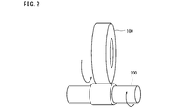
- FIG. 2 is a schematic diagram of a roller pitching test.
- FIG. 3 is a plan view of the Ono-type rotary bending fatigue test piece produced in the example.
- the C content of the steel material used for the induction hardened parts In order to increase the surface fatigue strength and bending fatigue strength of induction hardened parts, it is effective to increase the C content of the steel material used for the induction hardened parts. For example, when the C content is 0.40 mass% or more, high surface fatigue strength and bending fatigue strength can be obtained. However, if the C content of the steel material is high, the hardness of the steel material before cutting becomes high, and the machinability of the steel material deteriorates.
- the present inventors have set the C content of the steel material to 0.40% or more, while increasing the surface fatigue strength and bending fatigue strength of the induction hardened parts manufactured by induction hardening the steel material, while the C content is A steel material capable of maintaining a high machinability even at 0.40% or more was examined.
- the present inventors have found that the chemical composition is C: 0.40 to 0.70%, Si: 0.15 to 2.10%, Mn: 0.30 to 1.15% in mass%.
- the hardness of the surface of the induction-hardened component has a correlation with the C content and the Si content in the steel. Furthermore, the higher the hardness of the surface of the induction hardened component, the higher the surface fatigue strength of the induction hardened component. Therefore, the present inventors investigated and examined the relationship between the C content and Si content in the steel material and the surface fatigue strength of the induction-hardened part made of the steel material. As a result, they have found that if the C content and the Si content in the steel material satisfy the expression (1), the surface fatigue strength of the induction-hardened part made of the steel material can be increased. 290C+50Si+430 ⁇ 631.0 (1) Here, the content (mass %) of the corresponding element is substituted for each element symbol in the formula (1).
- FN1 290C+50Si+430.
- FN1 corresponds to the Vickers hardness of the quench-hardened layer formed on the surface layer of the induction-hardened component manufactured by induction-hardening the steel material and then tempering it at 300°C.
- the Vickers hardness of the quench-hardened layer formed on the surface layer of the induction-hardened component manufactured by induction hardening the steel material at 300° C. is referred to as “300° C. tempering hardness”.
- the surface fatigue strength of induction hardened parts obtained by the roller pitching fatigue test has a positive correlation with the 300°C tempered hardness.
- the present inventors investigated the relationship between the surface fatigue strength obtained by the roller pitching fatigue test and the 300° C. temper hardness. As a result, it was found that when the 300° C. temper hardness is 631.0 Hv or higher, a sufficiently high surface fatigue strength can be obtained in the induction-hardened part. Therefore, FN1 is set to 631.0 or more. In this case, a sufficiently high surface fatigue strength can be obtained in the induction-hardened component made of the steel material. When FN1 is less than 631.0, the surface fatigue strength of the induction-hardened component is low and pitting may occur.
- the content of Si, Mn, Cr, Mo, V, Cu, Ni and C which contributes to the improvement of hardenability, is proper in the chemical composition of the steel material that is the material of the induction hardened parts. It is effective to adjust the range. Specifically, when the content of each element in the chemical composition is within the above range and satisfies the formula (1), and further satisfies the following formula (3), the quench hardened layer of the induction hardened part The incompletely hardened structure can be suppressed, and the surface fatigue strength and bending fatigue strength of the induction hardened component can be increased.
- FN3 (1+0.7Si) ⁇ (1+3.3333Mn) ⁇ (1+2.16Cr) ⁇ (1+3.00Mo) ⁇ (1+1.73V) ⁇ (1+0.365Cu) ⁇ (1+0.363Ni) ⁇ (2.6616-1 .6C).
- FN3 is an index of the hardenability of steel materials. The harder the steel material, the higher the FN3.
- the present inventors have found that in steel materials in which the content of each element of the chemical composition is within the above-mentioned range and satisfy the formulas (1), (2), (4) and (5), FN3 and high frequency
- the relationship with the incompletely hardened structure in the hardened layer of the hardened part was investigated. As a result, it was found that when FN3 is 5.80 or more, the formation of an incompletely quenched structure can be sufficiently suppressed. Therefore, in other words, FN3 is set to 5.80 or more. If FN3 is 5.80 or more, the content of each element in the chemical composition is within the above-mentioned range, and formula (1), formula (2), formula (4) and formula (5) are satisfied.
- the inventors of the present invention performed a microstructure observation of a portion in which the hardness of the quench-hardened layer of the induction-hardened part varies. As a result, it was found that the cementite was not sufficiently melted during induction hardening in the high hardness portion of the quench-hardened layer, and the cementite remained unmelted. Therefore, the present inventors further investigated the chemical composition of cementite remaining unmelted. As a result, it was found that the cementite remaining unmelted in the quench-hardened layer had high Mn concentration and Cr concentration.
- the present inventors considered that the hardness variation of the quench-hardened layer of the induction-hardened parts is caused by the following factors.
- a heat treatment furnace is used. When heating a steel material in a heat treatment furnace, the steel material is heated at a high temperature for a long time. Therefore, the chemical composition of the steel material is in an equilibrium state, and cementite can be sufficiently solid-dissolved.
- induction hardening a steel material is heated in a short time by an induction heating device. Therefore, as compared with the heat treatment furnace, the high frequency heating device finishes heating before the chemical composition of the steel material reaches an equilibrium state.
- the chemical composition of the steel material during the high frequency heating is in a non-equilibrium state. Therefore, a part of cementite remains in the steel material after induction heating, and as a result, the amount of solid solution C varies, and as a result, the hardness of the quench hardened layer of the induction hardened component varies.
- the solution temperature of cementite in steel affects the amount of solid solution C during high frequency heating.
- Mn and Cr in cementite increase the solutionizing temperature of cementite. If the cementite contains Mn and Cr, the cementite is likely to remain unmelted even after high-frequency heating. As a result, the hardness of the quench-hardened layer of the induction-hardened component tends to vary, and the surface fatigue strength and bending fatigue strength decrease.
- the inventors of the present invention in the steel material in which the content of each element in the chemical composition is within the above range, by suppressing the Mn concentration and Cr concentration in cementite within appropriate ranges, induction hardening We thought that it was possible to suppress variations in the hardness of the quench-hardened layer of parts. Therefore, the present inventors investigated and studied the relationship between the Mn concentration and Cr concentration in cementite in the steel material and the surface fatigue strength and bending fatigue strength of the induction hardened parts.
- the solutionizing temperature of the cementite in the steel material is sufficiently low, and as a result, the cementite in the steel material sufficiently forms a solid solution during induction hardening. Therefore, variations in the hardness of the surface of the quench-hardened layer of the induction-hardened component are suppressed, and the surface fatigue strength and bending fatigue strength of the induction-hardened component are increased.
- the ferrite area ratio in the steel material affects the amount of solid solution C in the steel material by high frequency heating.
- the heating time is shorter than that of carburizing treatment using a heat treatment furnace. Therefore, the diffusion time of C during heating of the steel material also becomes short. In this case, the time required for solid solution of carbide such as cementite is also shortened.
- the area ratio of ferrite in the steel material tends to increase. If the ferrite area ratio in the steel material is too high, excessive ferrite will remain in the structure after induction hardening. If the ferrite area ratio is too high, low-carbon martensite is further produced. If ferrite remains or low-carbon martensite is produced, the hardness of the surface of the quench-hardened layer of the induction-hardened component varies.
- the present inventors further, the ferrite area ratio in the steel material content of each element of the chemical composition is within the above range, and the surface fatigue strength and bending fatigue of the induction hardened parts produced by induction hardening the steel material.
- the relationship with strength was investigated. As a result, if the ferrite area ratio in the steel material is 40% or less, it is assumed that the content of each element in the chemical composition is within the above range and that the formulas (1) to (5) are satisfied. It has been found that it is possible to suppress the variation in the hardness of the surface of the quench-hardened layer of the induction-hardened component manufactured by induction-hardening a steel material, and increase the surface fatigue strength and bending fatigue strength of the induction-hardened component.
- Induction-hardened parts even if the content of each element in the chemical composition is within the above-mentioned range and the steel material satisfies the formulas (1) to (5), if the ferrite area ratio in the steel material exceeds 40%. Ferrite remains in the quench hardened layer and low carbon martensite is generated. In this case, the hardness of the surface of the quench-hardened layer of the induction-hardened component tends to vary, and the surface fatigue strength and bending fatigue strength of the induction-hardened component decrease.
- the contents of C, Si, Mn, Cr, V and Mo affect the hardness of the steel material. If the hardness of the steel material is increased to some extent, the machinability of the steel material is significantly reduced. Therefore, in order to sufficiently maintain the machinability of the steel material, it is effective to adjust the hardness of the steel material within an appropriate range.
- the content of each element in the chemical composition is within the above range, and the expressions (1), (3) to (5) are satisfied.
- the surface fatigue strength and the bending fatigue strength of the induction-hardened parts manufactured by induction hardening the steel material on the premise that the ferrite area ratio is 40% or less and the martensite area ratio is 10% or less.
- FN2 is an index of hardness of steel. If FN2 is 0.900 or less, the content of each element in the chemical composition of the steel material is within the above-mentioned range, the equations (1), (3) to (5) are satisfied, and the ferrite area in the steel material is Assuming that the ratio is 40% or less and the martensite area ratio is 10% or less, while sufficiently increasing the surface fatigue strength and bending fatigue strength of the induction-hardened part manufactured by induction hardening the steel material, Sufficient machinability can be obtained even for steel materials.
- the induction hardened parts used as power transmission parts such as pinion gears have both high cycle bending fatigue strength and low cycle bending fatigue strength in bending fatigue strength. It is desirable to be excellent.
- B Boron segregates at grain boundaries in steel materials having the above chemical composition to enhance the grain boundary strength. Most of the cracks that occur in induction hardened parts during the use of induction hardened parts extend from grain boundaries. Therefore, if the grain boundary strength is increased by B, the extension of cracks at the grain boundaries can be suppressed. As a result, the low cycle fatigue strength of the induction-hardened part can be increased.
- the steel material of the present embodiment further satisfies the equation (4).
- the content (mass %) of the corresponding element is substituted for each element symbol in the formula (4).
- FN4 Ti-4 ⁇ N.
- FN4 is an index of grain boundary strengthening by B.
- the content of each element in the chemical composition is within the above range, the formulas (1) to (3) and the formula (5) are satisfied, and the ferrite area ratio in the steel material is 40%.
- the low cycle bending fatigue strength is also sufficiently increased, and Sufficient machinability can be obtained in steel materials.
- the steel material of this embodiment completed based on the above knowledge has the following configuration.
- the chemical composition is% by mass, C: 0.40 to 0.70%, Si: 0.15 to 2.10%, Mn: 0.30 to 1.15%, Cr: 0.01 to less than 0.50%, S: 0.005 to 0.070%, N: 0.0020 to 0.0200%, Ti: 0.0080 to 0.2000%, B: 0.0005 to 0.0050%, Al: 0.005 to 0.100%, and P: less than 0.050%,
- the balance consists of Fe and impurities, and satisfies the formulas (1) to (5),
- the ferrite area ratio is 40% or less, the martensite area ratio is 10% or less, Steel material.
- the steel material according to [1] The chemical composition is further replaced by a part of Fe, Mo: 1.00% or less, Ni: 1.00% or less, and Cu: 1.00% or less, containing one or more selected from the group consisting of, Steel material.
- the core is The chemical composition is% by mass, C: 0.40 to 0.70%, Si: 0.15 to 2.10%, Mn: 0.30 to 1.15%, Cr: 0.01 to less than 0.50%, S: 0.005 to 0.070%, N: 0.0020 to 0.0200%, Ti: 0.0080 to 0.2000%, B: 0.0005 to 0.0050%, Al: 0.005 to 0.100%, and P: less than 0.050%,
- the balance consists of Fe and impurities, and satisfies the formulas (1) to (5),
- the ferrite area ratio is 40% or less, the martensite area ratio is 10.0% or less, parts.
- the part according to [7], The chemical composition is further replaced by a part of Fe, Mo: 1.00% or less, Ni: 1.00% or less, and Cu: 1.00% or less, containing one or more selected from the group consisting of, parts.
- the component according to [7] or [8], The chemical composition is further replaced by a part of Fe, Ca: 0.0050% or less, Mg: 0.0050% or less, Te: 0.20% or less, and Rare earth element: 0.0050% or less, containing one or more selected from the group consisting of: parts.
- the component according to any one of [7] to [9], The chemical composition is further replaced by a part of Fe, Zr: 0.0050% or less, Nb: 0.20% or less, and V: 0.35% or less, containing one or more selected from the group consisting of: parts.
- the steel material of this embodiment is a material for induction hardening parts.
- a part manufactured by induction hardening the steel material of the present embodiment is referred to as an "induction hardened part".
- Induction-hardened parts are suitable for parts that require high surface fatigue strength and high bending fatigue strength.
- the steel material according to the present embodiment is a steel material that is a material for an induction-hardened component.
- the chemical composition of the steel material of this embodiment contains the following elements.
- Carbon (C) enhances surface fatigue strength and bending fatigue strength of an induction-hardened component manufactured by induction hardening a steel material. C further reduces the ferrite area ratio in the steel material. In this case, the hardenability in induction hardening can be improved, and the quench hardened layer depth of the induction hardened component can be increased. As a result, the surface fatigue strength and bending fatigue strength of the induction hardened parts are increased. If the C content is less than 0.40%, the above effects cannot be sufficiently obtained even if the content of other elements is within the range of the present embodiment.
- the C content is 0.40 to 0.70%.
- the preferable lower limit of the C content is 0.42%, more preferably 0.45%, further preferably 0.48%, further preferably 0.50%, further preferably 0.55. %.
- the preferable upper limit of the C content is 0.68%, more preferably 0.66%.
- Si 0.15 to 2.10%
- Silicon (Si) increases the temper softening resistance of the quench-hardened layer of the induction-hardened component manufactured by induction-hardening a steel material. As a result, the surface fatigue strength of induction hardened parts is increased. If the Si content is less than 0.15%, the above effect cannot be sufficiently obtained even if the content of other elements is within the range of this embodiment. On the other hand, if the Si content exceeds 2.10%, even if the content of other elements is within the range of this embodiment, decarburization is likely to occur during induction hardening. In this case, the surface fatigue strength and bending fatigue strength of the induction hardened parts are reduced. Therefore, the Si content is 0.15 to 2.10%.
- the preferable lower limit of the Si content is 0.25%, more preferably 0.35%, further preferably 0.40%, further preferably 0.45%, further preferably 0.50. %, more preferably 0.51%, further preferably 0.60%, further preferably 0.65%, further preferably 0.71%.
- the preferable upper limit of the Si content is 2.00%, more preferably 1.95%, further preferably 1.86%, and further preferably 1.80%.
- Mn 0.30 to 1.15%
- Mn Manganese
- S sulfur
- S is fixed and S is made harmless to improve the hot workability of the steel material. If the Mn content is less than 0.30%, the above effect cannot be sufficiently obtained even if the content of other elements is within the range of the present embodiment. On the other hand, if the Mn content exceeds 1.15%, the hardness of the steel material becomes too high even if the content of other elements is within the range of this embodiment. In this case, the machinability of the steel material deteriorates.
- the Mn content exceeds 1.15%, Mn of cementite in the steel material further forms a solid solution, and the solutionizing temperature of cementite increases.
- the cementite in the steel material does not sufficiently form a solid solution, and a part of the cementite remains undissolved.
- the Mn content is 0.30 to 1.15%.
- the preferable lower limit of the Mn content is 0.35%, more preferably 0.38%, further preferably 0.40%, further preferably 0.45%, further preferably 0.50.
- the preferable upper limit of the Mn content is 1.10% or less, more preferably 1.05%, further preferably 1.00% or less, and further preferably 0.95%.
- Chromium (Cr) enhances the hardenability of steel. Cr further enhances the hot workability of steel. If the Cr content is less than 0.01%, the above effects cannot be sufficiently obtained even if the content of other elements is within the range of the present embodiment. On the other hand, if the Cr content is 0.50% or more, even if the content of other elements is within the range of the present embodiment, Cr is excessively solid-dissolved in the cementite in the steel material to cause the cementite in the steel material. Solution temperature increases. In this case, in the induction hardening process, the cementite in the steel material does not sufficiently form a solid solution, and a part of the cementite remains undissolved.
- Cr Chromium
- the hardness of the surface of the quench-hardened layer of the induction hardened component varies, and the surface fatigue strength and bending fatigue strength of the induction hardened component decrease.
- the Cr content is less than 0.01%, the above effect cannot be sufficiently obtained.
- the Cr content is 0.50% or more, the hardness of the steel material becomes too high even if the content of other elements is within the range of this embodiment. In this case, the machinability of the steel material deteriorates. Therefore, the Cr content is 0.01 to less than 0.50%.
- the preferable lower limit of the Cr content is 0.02%, more preferably 0.03%, further preferably 0.05%, further preferably 0.07%, further preferably 0.10. %.
- the preferable upper limit of the Cr content is 0.45%, more preferably 0.40%, further preferably 0.35%, further preferably 0.32%, further preferably 0.30. %.
- S 0.005 to 0.070%
- Sulfur (S) combines with Mn in the steel to form MnS and enhances the machinability of the steel. If the S content is less than 0.005%, the above effects cannot be sufficiently obtained even if the content of other elements is within the range of the present embodiment. On the other hand, if the S content exceeds 0.070%, the bending fatigue strength of the induction-hardened component is reduced even if the content of other elements is within the range of this embodiment. When the S content exceeds 0.070%, further, when a magnetic particle flaw detection test is performed on the induction hardened component, a pseudo pattern is likely to occur on the surface of the induction hardened component, and the flaw detection accuracy decreases.
- the S content is 0.005% to 0.070%.
- the preferable lower limit of the S content is 0.007%, more preferably 0.010%, further preferably 0.012%, further preferably 0.014%.
- the preferable upper limit of the S content is 0.065%, more preferably 0.060%, further preferably 0.055%, further preferably 0.050%, further preferably 0.045. %, more preferably 0.040%, further preferably 0.035%, further preferably 0.030%.
- N 0.0020 to 0.0200%
- Nitrogen (N) combines with a nitride-forming element such as Al in the steel material to form a nitride.
- the nitride atomizes austenite in the induction hardening process. As a result, the bending fatigue strength of the induction hardened parts is increased.
- the N content is less than 0.0020%, the above effects cannot be sufficiently obtained even if the content of other elements is within the range of the present embodiment.
- the N content exceeds 0.0200%, the hot workability of the steel material deteriorates even if the content of other elements is within the range of this embodiment. Therefore, the N content is 0.0020 to 0.0200%.
- the preferable lower limit of the N content is 0.0025%, more preferably 0.0030%, further preferably 0.0033%, further preferably 0.0035%, further preferably 0.0038. %.
- the preferable upper limit of the N content is 0.0195%, more preferably 0.0150%, further preferably 0.0130%, further preferably 0.0100%.
- Titanium (Ti) combines with N to form a nitride. This suppresses the formation of B nitrides by combining B with N. In this case, B segregates at the grain boundaries to increase the grain boundary strength. As a result, the low cycle bending fatigue strength of the induction-hardened parts is particularly enhanced. If the Ti content is less than 0.008%, the above effects cannot be sufficiently obtained even if the content of other elements is within the range of this embodiment. On the other hand, if the Ti content exceeds 0.2000%, the steel material becomes brittle and the hot workability deteriorates even if the content of other elements is within the range of this embodiment. Therefore, the Ti content is 0.0080 to 0.2000%.
- the preferable lower limit of the Ti content is 0.0085%, more preferably 0.0090%, further preferably 0.0095%, further preferably 0.0100%, further preferably 0.0150. %, and more preferably 0.0200%.
- the preferable upper limit of the Ti content is 0.1900%, more preferably 0.1850%, further preferably 0.1800%, further preferably 0.1700%, further preferably 0.1500. %, more preferably 0.1000%, further preferably 0.0600%.
- B 0.0005 to 0.0050% Boron (B) segregates as a solid solution B at the grain boundaries in the steel material and enhances the grain boundary strength. In this case, the low-cycle bending fatigue strength of the induction-hardened part is increased. If the B content is less than 0.0005%, the above effects cannot be sufficiently obtained even if the content of other elements is within the range of the present embodiment. On the other hand, if the B content exceeds 0.0050%, the steel material becomes brittle even if the content of other elements is within the range of the present embodiment. In this case, hot workability deteriorates. Therefore, the B content is 0.0005 to 0.0050%.
- the preferable lower limit of the B content is 0.0007%, more preferably 0.0010%, further preferably 0.0012%, further preferably 0.0014%.
- the preferable upper limit of the B content is 0.0045%, more preferably 0.0040%, further preferably 0.0035%, further preferably 0.0030%, further preferably 0.0028. %.
- Al 0.005 to 0.100%
- Aluminum (Al) combines with N to form a nitride.
- the nitride atomizes austenite in the induction hardening process.
- Al further enhances the hardenability of the steel material. Therefore, the hardening layer depth of the quench hardening layer of the induction hardened part is increased.
- Al further enhances the machinability of the steel material. If the Al content is less than 0.005%, the above effects cannot be sufficiently obtained even if the content of other elements is within the range of the present embodiment.
- the Al content is 0.005 to 0.100%.
- the preferable lower limit of the Al content is 0.010%, more preferably 0.012%, further preferably 0.015%, further preferably 0.018%, further preferably 0. It is 020%.
- the preferable upper limit of the Al content is 0.090%, more preferably 0.080%, further preferably 0.070%, further preferably 0.060%, further preferably 0.050. %.
- Phosphorus (P) is an unavoidable impurity. That is, the P content is more than 0%. P reduces the toughness of the steel material. When the P content is 0.050% or more, the toughness of the steel material is significantly reduced even if the content of other elements is within the range of this embodiment. When the P content is 0.050% or more, the propagation of cracks generated in the induction-hardened component during use of the induction-hardened component is further promoted. In this case, the bending fatigue strength of the induction hardened part is reduced. Therefore, the P content is less than 0.050%.
- the preferable upper limit of the P content is 0.045%, more preferably 0.040%, and further preferably 0.035%. It is preferable that the P content is as low as possible. However, the dephosphorization treatment requires time and cost. Therefore, considering industrial productivity, the lower limit of the P content is preferably 0.001%, more preferably 0.002%, and further preferably 0.005%.
- the balance of the chemical composition of the steel material according to the present embodiment consists of Fe and impurities.
- the impurities are those that are mixed from the ore as a raw material, scrap, or the manufacturing environment when the steel material is industrially manufactured, and are allowed within a range that does not adversely affect the steel material of the present embodiment. Means what is done.
- the steel material of the present embodiment may further contain one or more kinds selected from the group consisting of Mo, Ni, and Cu, instead of part of Fe. All of these elements enhance the hardenability of steel materials.
- Mo Molybdenum
- Mo is an optional element and may not be contained. That is, the Mo content may be 0%. When it is contained, that is, when the Mo content is more than 0%, Mo enhances the hardenability of the steel material. Mo further enhances the temper softening resistance of the quench-hardened layer of the induction-hardened component, and increases the surface fatigue strength of the induction-hardened component. If Mo is contained even a little, the above effect can be obtained to some extent. However, if the Mo content exceeds 1.00%, the effect is saturated even if the content of other elements is within the range of this embodiment. Therefore, the Mo content is 1.00% or less. That is, the Mo content is 0 to 1.00%.
- the preferable lower limit of the Mo content is 0.01%, more preferably 0.05%, and further preferably 0.10%.
- the preferable upper limit of the Mo content is 0.60%, more preferably 0.40%, further preferably 0.30%.
- Nickel (Ni) is an optional element and may not be contained. That is, the Ni content may be 0%. When contained, that is, when the Ni content is more than 0%, Ni enhances the hardenability of the steel material. Further, Ni is concentrated on the surface of the steel material when it is oxidized, and suppresses the oxidation reaction of the steel material. If Ni is contained even a little, the above effect can be obtained to some extent. However, if the Ni content exceeds 1.00%, the machinability of the steel material deteriorates even if the content of other elements is within the range of this embodiment. Therefore, the Ni content is 1.00% or less. That is, the Ni content is 0 to 1.00%.
- the preferable lower limit of the Ni content is 0.01%, more preferably 0.05%, and further preferably 0.10%.
- the preferable upper limit of the Ni content is 0.80%, more preferably 0.60%.
- Cu 1.00% or less Copper (Cu) is an optional element and may not be contained. That is, the Cu content may be 0%. When it is contained, that is, when the Cu content is more than 0%, Cu is concentrated on the surface of the steel material when it is oxidized, and suppresses the oxidation reaction of the steel material. If Cu is contained even a little, the above effect can be obtained to some extent. However, if the Cu content exceeds 1.00%, the hot workability of the steel material deteriorates even if the content of other elements is within the range of this embodiment. Therefore, the Cu content is 1.00% or less. That is, the Cu content is 0 to 1.00%.
- the preferable lower limit of the Cu content is 0.01%, more preferably 0.05%, and further preferably 0.10%.
- the preferable upper limit of the Cu content is 0.80%, more preferably 0.60%.
- the steel material of the present embodiment may further contain one or more selected from the group consisting of Ca, Mg, Te, and a rare earth element (REM), instead of part of Fe. All of these elements enhance high cycle bending fatigue strength.
- REM rare earth element
- Ca 0.0050% or less
- Calcium (Ca) is an optional element and may not be contained. That is, the Ca content may be 0%. When it is contained, that is, when the Ca content is more than 0%, Ca forms a solid solution in MnS to make MnS finer or suppress the elongation of MnS. Therefore, the bending fatigue strength of the induction hardened parts is increased. If Ca is contained even in a small amount, the above effect can be obtained to some extent. However, if the Ca content exceeds 0.0050%, the hot workability of the steel material deteriorates. Therefore, the Ca content is 0.0050% or less. That is, the Ca content is 0 to 0.0050%.
- the preferable lower limit of the Ca content is 0.0001%, more preferably 0.0003%, and further preferably 0.0005%.
- the preferable upper limit of the Ca content is 0.0045%, more preferably 0.0040%, further preferably 0.0030%, further preferably 0.0025%.
- Mg 0.0050% or less
- Magnesium (Mg) is an optional element and may not be contained. That is, the Mg content may be 0%. When it is contained, that is, when the Mg content is more than 0%, Mg forms a solid solution with MnS to make MnS fine, or suppresses the elongation of MnS. Therefore, the bending fatigue strength of the induction hardened parts is increased. If Mg is contained even a little, the above effect can be obtained to some extent. However, if the Mg content exceeds 0.0050%, the hot workability of the steel material deteriorates. Therefore, the Mg content is 0.0050% or less. That is, the Mg content is 0 to 0.0050%.
- the preferable lower limit of the Mg content is 0.0001%, more preferably 0.0003%, and further preferably 0.0005%.
- the preferable upper limit of the Mg content is. It is 00048%, more preferably 0.0040%, further preferably 0.0030%, further preferably 0.0025%.
- Te 0.20% or less
- Tellurium (Te) is an optional element and may not be contained. That is, the Te content may be 0%. When it is contained, that is, when the Te content is more than 0%, Te forms a solid solution with MnS to make MnS fine, or suppress the elongation of MnS. Therefore, the bending fatigue strength of the induction hardened parts is increased. If Te is contained even a little, the above effect can be obtained to some extent. However, if the Te content exceeds 0.20%, the hot workability of the steel material deteriorates. Therefore, the Te content is 0.20% or less. That is, the Te content is 0 to 0.20%.
- the preferable lower limit of the Te content is 0.01%, more preferably 0.02%, and further preferably 0.05%.
- the preferable upper limit of the Te content is 0.18%, more preferably 0.15%, further preferably 0.10%.
- the rare earth element (REM) is an optional element and may not be contained. That is, the REM content may be 0%. When it is contained, that is, when the REM content is more than 0%, REM forms a solid solution with MnS to make MnS fine, or suppresses MnS stretching. Therefore, the bending fatigue strength of the induction hardened parts is increased. If REM is contained even a little, the above effect can be obtained to some extent. However, if the REM content exceeds 0.0050%, even if the content of other elements is within the range of the present embodiment, the generation of the composite oxide composed of the oxide and the sulfide is promoted, and the composite oxide becomes coarse.
- the REM content is 0.0050% or less. That is, the REM content is 0 to 0.0050%.
- the preferable lower limit of the REM content is 0.0001%, more preferably 0.0003%, and further preferably 0.0005%.
- the preferable upper limit of the REM content is 0.0045%, more preferably 0.0040%.
- REM in this specification means scandium (Sc) having an atomic number of 21, an yttrium (Y) having an atomic number of 39, and a lanthanide having an atomic number of 57, lanthanum (La) to an atomic number of 71. It is one or more elements selected from the group consisting of lutetium (Lu). Further, the REM content in this specification is the total content of these elements.
- the steel for induction hardening of the present embodiment may further contain one or more selected from the group consisting of Zr, Nb and V, instead of part of Fe.
- Zr Zirconium
- Zr Zirconium
- the Zr content may be 0%.
- Zr combines with N to form a nitride. This nitride atomizes austenite in the induction hardening process. As a result, the bending fatigue strength of induction hardened parts is increased. If the Zr content is small, the above effect can be obtained to some extent. However, if the Zr content exceeds 0.0050%, even if the content of other elements is within the range of this embodiment, coarse precipitates are generated, and the bending fatigue strength of the induction-hardened component is rather lowered. To do.
- the Zr content exceeds 0.0050%, the steel material becomes more brittle. Therefore, the Zr content is 0.0050% or less. That is, the Zr content is 0 to 0.0050%.
- the preferable lower limit of the Zr content is 0.0001%, more preferably 0.0003%, further preferably 0.0005%, and further preferably 0.0010%.
- the preferable upper limit of the Zr content is 0.0048%, more preferably 0.0045%, and further preferably 0.0040%.
- Niobium (Nb) is an optional element and may not be contained. That is, the Nb content may be 0%. When contained, that is, when the Nb content is more than 0%, Nb combines with N to form a nitride. This nitride atomizes austenite in the induction hardening process. As a result, the bending fatigue strength of induction hardened parts is increased. The above effect can be obtained to some extent if the Nb content is small. However, if the Nb content exceeds 0.20%, the effect is saturated. Therefore, the Nb content is 0.20% or less. That is, the Nb content is 0 to 0.20%.
- the preferable lower limit of the Nb content is 0.01%, more preferably 0.02%, and further preferably 0.05%.
- the preferable upper limit of the Nb content is 0.19%, more preferably 0.18%, and further preferably 0.15%.
- V 0.35% or less
- Vanadium (V) is an optional element and may not be contained. That is, the V content may be 0%. When contained, that is, when the V content is more than 0%, that is, when the V content is more than 0%, V combines with N to form a nitride. This nitride atomizes austenite in the induction hardening process. As a result, the bending fatigue strength of induction hardened parts is increased. If the Zr content is small, the above effect can be obtained to some extent. However, if the V content exceeds 0.35%, the effect is saturated. Therefore, the V content is 0.35% or less. That is, the V content is 0 to 0.35%.
- the preferable lower limit of the V content is 0.01%, more preferably 0.02%, and further preferably 0.05%.
- the preferable upper limit of the V content is 0.30%, more preferably 0.25%.
- the steel for induction hardening of this embodiment may further contain Sb instead of part of Fe.
- Antimony (Sb) is an optional element and may not be contained. That is, the Sb content may be 0%. When contained, that is, when the Sb content is more than 0%, Sb segregates on the surface of the steel material and suppresses oxidation of the steel material. If Sb is contained even in a small amount, the above effect can be obtained to some extent. However, if the Sb content exceeds 0.015%, the toughness and hot workability of the steel material deteriorate. Therefore, the Sb content is 0.015% or less. That is, the Sb content is 0 to 0.015%.
- the preferable lower limit of the Sb content is 0.001%, more preferably 0.003%, and further preferably 0.005%.
- the preferable upper limit of the Sb content is 0.014%, more preferably 0.010%, and further preferably 0.008%.
- the steel for induction hardening of this embodiment may further contain Pb instead of part of Fe.
- Pb 0.09% or less
- Lead (Pb) is an optional element and may not be contained. That is, the Pb content may be 0%. When contained, Pb enhances the machinability of the steel material. If Pb is contained even a little, the above effect can be obtained to some extent. However, if the Pb content exceeds 0.09%, the toughness and hot workability of the steel material deteriorate. Therefore, the Pb content is 0.09% or less. That is, the Pb content is 0 to 0.09%.
- the preferable lower limit of the Pb content is 0.01%, and more preferably 0.02%.
- the preferable upper limit of the Pb content is 0.08%, more preferably 0.07%.
- FN1 is an index of the hardness of the steel surface. FN1 is approximately equivalent to the Vickers hardness (300° C. tempering hardness) of the surface of the induction-hardened component that has been tempered at 300° C. after induction hardening.
- the surface fatigue strength of induction hardened parts has a positive correlation with 300° C. temper hardness. Therefore, if the 300° C. tempering hardness is sufficiently increased, the induction-hardened component exhibits excellent surface fatigue strength.
- FN1 When FN1 is 631.0 or more, the content of each element in the chemical composition of the steel material is within the range of the present embodiment, the formulas (2) to (5) are satisfied, and the ferrite area ratio is Sufficient surface fatigue strength can be obtained in the induction-hardened parts produced by induction hardening the steel material on the assumption that the content is 40% or less. On the other hand, if FN1 is less than 631.0, the surface fatigue strength of the induction-hardened component may decrease, and pitting may occur. Therefore, FN1 is 631.0 or more.
- the preferable lower limit of FN1 is 635.0, more preferably 638.0, further preferably 640.0, further preferably 642.0, and further preferably 644.0.
- the upper limit of FN1N is not particularly limited. However, in the case of the above chemical composition, the preferable upper limit of FN1 is 738.0, more preferably 700.0, further preferably 680.0, and further preferably 665.0.
- FN2 is an index of hardness of steel. If FN2 exceeds 0.900, the machinability of the steel material deteriorates. If FN2 is 0.900 or less, the content of each element in the chemical composition of the steel material is within the above-mentioned range, the equations (1), (3) to (5) are satisfied, and the ferrite area in the steel material is Assuming that the ratio is 40% or less, the machinability of the steel material becomes sufficiently high. Therefore, FN2 is 0.900 or less.
- the preferable upper limit of FN2 is 0.895, more preferably 0.890, and further preferably 0.885.
- the preferable lower limit of FN2 is 0.483, more preferably 0.600, further preferably 0.700, further preferably 0.750, and further preferably 0.800.
- the steel material of the present embodiment further satisfies Expression (3).
- the content (mass %) of the corresponding element is substituted for each element symbol in the formula (3).
- "0" is substituted for the element symbol.
- FN3 (1+0.7Si) ⁇ (1+3.3333Mn) ⁇ (1+2.16Cr) ⁇ (1+3.00Mo) ⁇ (1+1.73V) ⁇ (1+0.365Cu) ⁇ (1+0.363Ni) ⁇ (2.6616-1 .6C).
- FN3 is an index of the hardenability of steel materials. When FN3 is less than 5.80, the hardenability of the steel material is not sufficient. In this case, an incompletely hardened structure is generated in the quench hardened layer of the induction hardened part. Therefore, the surface fatigue strength and bending fatigue strength of the induction hardened parts are reduced.
- FN3 When FN3 is 5.80 or more, the content of each element in the chemical composition is within the above range, and the formula (1), the formula (2), the formula (4) and the formula (5) are satisfied, Assuming that the surface area of ferrite is 40% or less, sufficient surface fatigue strength and sufficient bending fatigue strength can be obtained in induction-hardened parts.
- the preferable lower limit of FN3 is 5.85, more preferably 5.90, further preferably 5.95, further preferably 6.00, and further preferably 6.05.
- the preferable upper limit of FN3 is 70.00, more preferably 60.00, further preferably 50.00, further preferably 45.00, further preferably 40.00, and further preferably Is 35.00.
- the steel material of the present embodiment further satisfies Expression (4).
- Expression (4) Ti-4 ⁇ N ⁇ 0 (4)
- the content (mass %) of the corresponding element is substituted for each element symbol in the formula (4).
- FN4 Ti-4 ⁇ N.
- FN4 is an index of grain boundary strengthening by B. If FN4 is less than 0, the amount of Ti that fixes N is not sufficient. In this case, N combines with B to form BN, and the amount of solid solution B decreases. Therefore, the grain boundary strengthening by the solid solution B is not sufficient, and the bending fatigue strength of the induction-hardened parts, especially in low cycles, is reduced.
- FN4 when FN4 is 0 or more, the content of each element in the chemical composition is within the above range, the formulas (1) to (3) and (5) are satisfied, and the ferrite area ratio in the steel material is Assuming that the content is 40% or less, the surface fatigue strength and the high cycle bending fatigue strength of the induction hardened parts produced by induction hardening the steel material are sufficiently increased, while the low cycle bending fatigue strength is also sufficiently increased.
- the preferable lower limit of FN4 is 0.001, more preferably 0.002, and further preferably 0.003.
- the steel material of the present embodiment further satisfies Expression (5). 9.7 Mn ⁇ +32.4Cr ⁇ ⁇ 25.9 (5)
- the Mn concentration (mass %) in the cementite is substituted for Mn ⁇ in the equation (5).
- the Cr concentration (mass %) in the cementite is substituted for Cr ⁇ in the equation (5).
- FN5 is 25.9 or less
- the solutionizing temperature of cementite in the steel material is sufficiently low, and as a result, the cementite in the steel material is sufficiently solid-dissolved in induction hardening. Therefore, variations in the hardness of the surface of the quench-hardened layer of the induction-hardened component are suppressed, and the surface fatigue strength and bending fatigue strength of the induction-hardened component are sufficiently increased. Therefore, FN5 is 25.9 or less.
- the preferable upper limit of FN5 is 22.0, more preferably 21.0, and further preferably 20.0.
- the preferable lower limit of FN5 is 1.0, more preferably 1.5, further preferably 2.0, and further preferably 2.5.
- the Mn concentration (mass %) and Cr concentration (mass %) in the cementite in the steel material are measured by the electrolytic extraction residue. Specifically, it measures by the following method. Take a test piece from any position of the steel product. Constant current electrolysis is performed on the test piece using a 10% AA-based electrolytic solution. It means a liquid obtained by mixing a 10% AA-based electrolyte solution with tetramethylammonium chloride, acetylacetone, and methanol at a volume ratio of 1:10:100.
- the residue is collected by suction filtration with a filter having a mesh size of 0.2 ⁇ m.
- An acid decomposition treatment is performed on the collected residue.
- ICP-AES high frequency inductively coupled plasma atomic spectroscopy analysis
- Cr ⁇ (mass %) is calculated.
- the ferrite area ratio is 40% or less and the martensite area ratio is 10% or less.
- the ferrite area ratio in the steel material affects the amount of solute C in the steel material in the high frequency heating.
- the heating time is shorter than that of carburizing treatment using a heat treatment furnace. Therefore, the diffusion time of C during heating of the steel material also becomes short. In this case, the time required for solid solution of carbide such as cementite is also shortened. As a result, the area ratio of ferrite in the steel material tends to increase.
- the ferrite area ratio in the steel material is too high, excessive ferrite will remain in the structure after induction hardening. If the ferrite area ratio is too high, low-carbon martensite is further generated in the structure after induction hardening. If ferrite remains or low-carbon martensite is produced, the hardness of the surface of the quench-hardened layer of the induction-hardened component varies. If the ferrite area ratio in the steel material exceeds 40%, the hardness will vary on the surface of the quench-hardened layer of the induction-hardened component. As a result, the surface fatigue strength and bending fatigue strength of the quench-hardened layer of the induction-hardened component are reduced.
- the ferrite area ratio is 40% or less, it is assumed that the content of each element in the chemical composition is within the above range and the formulas (1) to (5) are satisfied, and the steel material is induction hardened. It is possible to sufficiently suppress variations in the hardness of the surface of the quench-hardened layer of the induction-hardened component manufactured by the above method. As a result, the surface fatigue strength and bending fatigue strength of the induction hardened parts are sufficiently increased.
- the above-mentioned ferrite area ratio (%) means the area ratio (%) of polygonal ferrite.
- the rest of the microstructure other than ferrite is martensite and/or pearlite.
- the martensite area ratio is 10% or less.
- "martensite” includes not only martensite but also bainite. Martensite and bainite are extremely difficult to distinguish by microscopic observation. Therefore, in the present specification, martensite and bainite are referred to as “martensite”.
- the preferable upper limit of the martensite area ratio is 7%, more preferably 5%, and further preferably 4%.
- the ferrite area ratio (%) in the steel material can be obtained by the following method.
- a test piece for microstructure observation is taken from any position of the steel material.
- a cross section (hereinafter referred to as an observation surface) perpendicular to the longitudinal direction (axial direction) of the steel material is polished.
- the observation surface after polishing is etched using a nital etchant.
- the etched viewing surface is viewed under a 400x optical microscope to produce a photographic image. Identify the ferrite in the photographic image.
- a phase having a lamellar structure can be specified as pearlite.
- Areas with higher brightness (white areas) than pearlite can be specified as ferrite. It is possible to specify martensite as a region (dark region) having a lower brightness than that of ferrite and pearlite.
- the area ratio of the specified ferrite is measured by the point calculation method according to JIS G 0555 (2003). The measured area ratio is defined as the ferrite area ratio (%) in the steel material. Further, the area ratio of the specified martensite is measured by the above point calculation method. The measured area ratio is defined as the area ratio (%) of martensite in the steel material.
- the content of each element in the chemical composition is within the range of the present embodiment, the expressions (1) to (5) are satisfied, and the ferrite area ratio in the steel material is 40%. And the martensite area ratio is 10% or less. Therefore, while sufficiently improving the surface fatigue strength and high cycle bending fatigue strength of the induction hardened parts produced by induction hardening of the steel material, the low cycle bending fatigue strength is also sufficiently increased, and the sufficient workability of the steel material is improved. Sex is obtained.
- the induction-hardened component of this embodiment is made of the steel material of this embodiment. Specifically, the induction hardened part of this embodiment is manufactured by induction hardening the steel material of this embodiment.
- the induction hardening component is used as a power transmitting component represented by a differential gear, for example.
- ⁇ Induction-hardened parts include parts that have been induction hardened as a whole, as well as parts that have been induction hardened. That is, in the present specification, the induction-hardened component may include a hardened portion that is an induction-hardened portion and an unquenched portion that is not induction-hardened. When the entire component is induction hardened, the entire component corresponds to the quenched portion.
- the induction-hardened component of this embodiment includes a quench-hardened layer and a core.
- the quench-hardened layer is formed on the surface layer (of the quenched portion) of the induction-hardened component.
- the quench-hardened layer is formed by performing induction hardening.
- the core portion is a portion of the induction-hardened component that is inside the quench-hardened layer and is not affected by the induction-quenching.
- the martensite area ratio is 90% or more.
- the balance of the microstructure is ferrite.
- martensite includes tempered martensite and further includes bainite. Martensite has almost no carbide in the lath. On the other hand, tempered martensite and bainite have many precipitates in the lath and at the lath interface. However, in the present specification, the two are not strictly classified, and all are regarded as “martensite”.
- the balance of the microstructure of the quench-hardened layer is ferrite.
- the microstructure of the quench hardened layer can be obtained by the following method.
- induction-hardened parts take a sample from the effective hardened layer defined by JIS G 0559 (2008). After polishing the surface of the sample (referred to as an observation surface) to a mirror surface, the sample is immersed in a nital corrosive solution to reveal the structure by etching. The etched observation surface is observed with a 400 ⁇ optical microscope to generate a photographic image. From the observation surface, three arbitrary visual fields are observed. The area of each visual field is 130 ⁇ m ⁇ 260 ⁇ m. In each visual field, each phase such as martensite, ferrite, and pearlite can be distinguished from the contrast.
- a phase having a lamellar structure can be identified as pearlite.
- Areas with higher brightness (white areas) than pearlite can be specified as ferrite. It is possible to specify martensite as a region (dark region) having a lower brightness than that of ferrite and pearlite.
- the chemical composition of the quench-hardened layer is the same as that of the steel material of this embodiment. That is, the content of each element in the chemical composition of the quench-hardened layer is within the range of this embodiment and satisfies the formulas (1) to (4).
- the core portion is a portion of the induction-hardened component that is inside the quench-hardened layer and is not affected by the induction hardening.
- the chemical composition and microstructure of the core portion are the same as the chemical composition and microstructure of the steel material of this embodiment. That is, the core portion has the content of each element in the chemical composition within the range of the present embodiment, satisfies the formulas (1) to (5), the ferrite area ratio in the microstructure is 40% or less, and The balance of the tissue is perlite and/or martensite. The martensite area ratio is 10% or less.
- the chemical composition of the core, the ferrite area ratio in the microstructure, the Mn concentration Mn theta and Cr concentration Cr theta in cementite determined by the following method.
- a portion inside the effective hardened layer defined by JIS G 0559 (2008) is defined as a core portion.
- a sample is taken from the core of the induction hardened part.
- a well-known component analysis method is implemented using the sample taken. Specifically, a drill is used to generate chips from the sample, and the chips are collected.
- a solution is obtained by dissolving the collected cutting chips in acid.
- the solution is subjected to ICP-AES (Inductively Coupled Plasma Atomic Emission Spectrometry) to perform elemental analysis of the chemical composition.
- ICP-AES Inductively Coupled Plasma Atomic Emission Spectrometry
- the C content and the S content are determined by the well-known high frequency combustion method (combustion-infrared absorption method).
- the N content is determined by using the well-known inert gas melting-thermal conductivity method. Furthermore, using a sample, in the same way as the steel material of the present embodiment, the ferrite area ratio in the microstructure, and to determine the Mn concentration Mn theta and Cr concentration Cr theta in cementite.
- the induction hardened parts of the present embodiment may be induction hardened as a whole, or may be partly induction hardened and the other parts may not be induction hardened.
- the induction-hardened component only needs to include the induction-hardened portion.
- the induction hardened part is referred to as a "hardened part”
- the part that is not induction hardened is referred to as an "unhardened part”.
- the steel material used as the material for the induction hardened parts is manufactured by performing a normalizing process. The surface of the steel material manufactured by the normalizing treatment is then machined (cutting, etc.). Therefore, the surface of the steel material after machining has a metallic luster.
- Induction hardening is performed on a part of the machined steel material to produce an induction hardened part. Therefore, the surface of the hardened part of the induction-hardened part is discolored (colored) by the heating during the induction hardening. On the other hand, the surface of the unquenched part of the induction-hardened part maintains a metallic luster. Therefore, those skilled in the art can easily distinguish between the hardened part and the unhardened part by observing the appearance of the induction hardened part.
- the quenched portion includes the above-mentioned quench hardened layer and the core portion.
- the induction hardened parts of this embodiment are manufactured by induction hardening the steel material of this embodiment. Therefore, it is excellent in surface fatigue strength and high cycle bending fatigue strength. Furthermore, it is also excellent in low cycle bending fatigue strength.
- the method for manufacturing a steel material according to this embodiment includes a material preparing step, a hot working step, and a normalizing step. Hereinafter, each step will be described in detail.
- a material is prepared in which the content of each element in the chemical composition is within the range of the present embodiment and the formulas (1) to (4) are satisfied.
- molten steel is produced in which the content of each element in the chemical composition is within the range of the present embodiment and the formulas (1) to (4) are satisfied.
- a slab slab or bloom
- a steel ingot is produced by a known casting method.
- a raw material (a slab or an ingot) is manufactured through the above steps.
- Hot working process hot working is performed on a raw material (a slab or a steel ingot) to manufacture an intermediate steel material.
- the intermediate steel materials are, for example, steel bars and wire rods.
- the hot working includes a rough rolling process and a finish rolling process.
- the material is hot worked to produce a billet.
- the rough rolling process uses, for example, a slab mill.
- a slab mill is used to slab the material to produce a billet.
- a continuous rolling mill is installed downstream of the slab, the billet after slabbing is further hot-rolled using a continuous rolling mill to produce a smaller billet. May be.
- a horizontal stand having a pair of horizontal rolls and a vertical stand having a pair of vertical rolls are alternately arranged in a line.
- the heating temperature in the rough rolling step is not particularly limited, but is, for example, 1100 to 1300°C.
- the billet is heated using a heating furnace or soaking furnace.
- the billet after heating is subjected to hot rolling using a continuous rolling mill to manufacture a steel material (bar steel).
- the heating temperature at the finish rolling temperature is not particularly limited, but is, for example, 1000 to 1300°C.
- the finish rolling temperature is not particularly limited, but is, for example, 900 to 1100°C. After finish rolling, it is cooled to produce an intermediate steel material.
- the hot rolling process was taken as an example.
- the steel material of the present embodiment may be subjected to a hot forging step as the hot working step instead of the hot rolling step.
- a hot rolling step and a hot forging step after the hot rolling step may be performed.
- the shape of the steel material of the present embodiment may be a steel bar or a wire material, or may have a predetermined shape formed by hot forging.
- the normalizing treatment is carried out on the intermediate steel material produced in the hot working step to produce a steel material satisfying the formula (5).
- the intermediate steel material is loaded into a heat treatment furnace (normalizing furnace). Then, the intermediate steel material is held at the normalizing temperature of 800 to 950° C. for 30 minutes to 2 hours. The held intermediate steel material is extracted from the heat treatment furnace and cooled. At this time, the average cooling rate CR in the temperature range of 700 to 300° C., which is the cementite production temperature range, is set to 0.10 to 1.00° C./sec. When the average cooling rate CR is less than 0.10° C./second, the Mn concentration Mn ⁇ and the Cr concentration Cr ⁇ in cementite increase and FN5 does not satisfy the formula (5).
- the average cooling rate CR exceeds 1.00° C./sec, the area ratio of martensite in the microstructure in the steel material increases and the machinability decreases. If the average cooling rate CR in the temperature range of 700 to 300° C. is 0.10 to 1.00° C./sec, the Mn concentration Mn ⁇ and the Cr concentration Cr ⁇ in the menthite can be suppressed, and as a result, FN5 becomes ) Is satisfied.
- the steel material of this embodiment is manufactured by the above manufacturing process. That is, the steel material of the present embodiment is manufactured by carrying out the normalizing treatment so that the average cooling rate CR becomes 0.10 to 1.00° C./sec.
- the method for manufacturing an induction-hardened component according to the present embodiment includes a forging process, a machining process, an induction hardening process, and a tempering process that are performed as necessary.
- the intermediate member is subjected to cutting or punching to give it a shape. By performing machining, a precise shape can be imparted to the steel material.
- induction hardening process In the induction hardening step, induction hardening is performed on the steel material after the machining step to manufacture an induction hardening part.
- Induction hardening may be performed by a known method.
- the hardening temperature (maximum heating temperature) is set to 850 to 1100°C.
- the quenching temperature is 850° C. or higher, sufficient quenching can be performed on the steel material. In this case, a quench hardened layer is formed.
- the holding time at the quenching temperature is not particularly limited, but is preferably 0.5 to 60 seconds, for example.
- Tempeering process A well-known tempering process is performed on the steel material after the induction hardening process.
- the tempering temperature is, for example, 100 to 200°C.
- the holding time at the tempering temperature is, for example, 90 to 150 minutes.
- the induction hardened parts having the above-mentioned structure are manufactured.
- the conditions in the examples are one condition example adopted to confirm the feasibility and effects of the steel material of the present embodiment. Therefore, the steel material of the present embodiment is not limited to this one condition example.
- Blank areas in Tables 1 and 2 mean that the content of the corresponding element was below the detection limit.
- the blank portion means that it was below the detection limit at the lowest digit of the corresponding element content.
- the smallest digit is the second decimal place. Therefore, it means that the Mo content of Test No. 1 was not detected in the number of digits up to the second decimal place (the significant figure was 0% in the content up to the second decimal place).
- the manufactured ingot was subjected to hot rolling (rough rolling process and finish rolling process) to manufacture an intermediate steel material (bar steel).
- the heating temperatures of the roughly rolled steel products were all within the range of 1100 to 1300°C. Further, the heating temperature in the finish rolling step was in the range of 1200 to 1250°C. Further, the finish rolling temperature was in the range of 900 to 1100°C.
- hot forging hot forging
- the intermediate steel material after hot forging was allowed to cool (Table 3 and In the column of "hot forging” in Table 4, "execution” is described).
- Test Nos. 1 to 63 the samples were allowed to cool without hot forging after hot rolling. Through the above steps, a steel bar (intermediate steel material) having a diameter of 30 to 100 mm was manufactured.
- Normalizing treatment was performed on the intermediate steel materials of test numbers 1 to 61, 64 and 65. Specifically, the intermediate steel materials having these test numbers were placed in a heat treatment furnace (normalizing furnace) and kept at 850° C. for 1 hour. Air-cooling, oil-cooling, or water-cooling was performed on the held intermediate steel material.
- the average cooling rate CR at 700 to 300° C. was as shown in Tables 3 and 4 (described in the column “Average cooling rate CR (° C./sec)” in Tables 3 and 4). In test numbers 62 and 63, normalizing treatment was not performed.
- ICP-AES high frequency inductively coupled plasma atomic spectroscopy analysis
- the ferrite area ratio (%) in the steel material of each test number was obtained by the following method.
- a test piece for microstructure observation was taken from an arbitrary position of the steel material.
- a cross section (observation surface) perpendicular to the longitudinal direction (axial direction) of the steel material was polished.
- the observation surface after polishing was etched using a Nital etchant.
- the etched observation surface was observed with a 400 ⁇ optical microscope to generate a photographic image. In the photographic image, ferrite and martensite were identified by the method described above.
- the area ratio of the specified ferrite was measured by the point calculation method based on JIS G 0555 (2003).
- the measured area ratio was defined as the ferrite area ratio in the steel material.
- the obtained ferrite area ratio is shown in the "ferrite area ratio (%)" column of the "steel material” column in Tables 3 and 4.
- the area ratio of the specified martensite was measured by the point calculation method based on JIS G 0555 (2003).
- the measured area ratio was defined as the martensite area ratio in the steel material.
- the obtained martensite area ratio is shown in the "martensite area ratio (%)” column of the "steel material” column in Tables 3 and 4.
- Machinability evaluation test Machinability was evaluated using the steel material of each test number. First, in order to evaluate the drill machinability, a test piece was prepared from the center of a steel bar having a diameter of 30 to 100 mm. The test piece was cylindrical and had a length of 21 mm. The longitudinal direction of the test piece was parallel to the longitudinal direction of the steel bar.
- a drill drilling test was conducted using a model SD3.0 drill manufactured by Fujikoshi Co., Ltd.
- the feed amount per rotation was 0.25 mm, and the perforation depth of one hole was 9 mm.
- Water-soluble cutting oil was used as a lubricant.
- the maximum cutting speed VL1000 capable of cutting up to a cumulative hole depth of 1000 mm was obtained.
- Evaluation A Maximum cutting speed VL1000 is 50 m/min or more
- Evaluation B Maximum cutting speed VL1000 is 45 m/min or more and less than 50 m/min
- Evaluation C Maximum cutting speed VL1000 is 40 m/min or more and less than 45 m/min
- Evaluation X Maximum cutting speed When VL1000 was less than 40 m/min and the evaluations A to C, it was judged that the machinability was excellent. In the case of evaluation X, it was judged that the machinability was low.
- the evaluation results are shown in the "Machinability" column of the "Steel” column in Tables 3 and 4.
- test piece 200 The surface fatigue strength of induction hardened parts was evaluated by the following method. By machining (cutting) the steel material of each test number, the small roller test piece 200 shown in FIG. 1 (hereinafter, simply referred to as the test piece 200) was manufactured. When the diameter of the steel material was less than 80 mm, the test piece 200 was sampled so that the center position of the cross section of the test piece 200 perpendicular to the longitudinal direction was the center position of the cross section of the steel material perpendicular to the longitudinal direction. The longitudinal direction of the test piece 200 was parallel to the longitudinal direction of the steel material.
- the center position of the cross section perpendicular to the longitudinal direction of the test piece 200 is the center position of the radius R (that is, the 2/R position) of the cross section perpendicular to the longitudinal direction of the steel material.
- the test piece 200 was sampled so that The longitudinal direction of the test piece 200 was parallel to the longitudinal direction of the steel material.
- Numerals in Fig. 1 indicate dimensions. “ ⁇ ” in FIG. 1 means a diameter. That is, “ ⁇ 22” means that the diameter is 22 mm.
- the test piece 200 had a columnar shape, and had a parallel portion with a diameter of 26 mm at the center position in the longitudinal direction of the test piece 200. The diameter of the cylindrical portion of the test piece 200 other than the parallel portion was 22 mm.
- Induction hardening was performed on the test piece 200. Specifically, the heating temperature was 1000° C. and the heating time was 20 seconds. The heated test piece 200 was cooled with water. The test piece 200 after induction hardening was tempered at a tempering temperature of 150° C. for 1 hour. Through the above steps, the test piece 200, which is an induction-hardened component, was manufactured. A plurality of induction-hardened parts (test piece 200) were manufactured for each test number.
- test piece 200 Using the test piece 200, a roller pitching test shown in FIG. 2 was performed to evaluate the surface fatigue strength of the induction hardened parts. Specifically, referring to FIG. 2, test piece 200 was rotated while pressing large roller test piece 100 against test piece 200. As the large roller test piece 100, a steel material having a chemical composition equivalent to SCM722 specified in JIS G 4053 (2016) was carburized and then surface-polished. The radius of the large roller test piece 100 was 130 mm.
- the large roller test piece 100 was pressed against the test piece 200 with a surface pressure of various Hertz stresses.
- the circumferential speed direction of both roller test pieces (test piece 200, large roller test piece 100) at the contact portion is the same direction, and the slip ratio is -40% (the large roller test piece 100 is more contact than the test piece 200 at the contact portion.
- the peripheral speed is 40% higher).
- the oil temperature of ATF (lubricating oil for AT) supplied as lubricating oil to the contact portion was 80°C.
- the contact stress between the large roller test piece 100 and the test piece 200 was set to 3000 to 3300 MPa.
- the number of times the test was terminated was set to 10 million (10 7 times).
- the induction hardened part (test piece 100) was evaluated to have excellent surface fatigue strength. Specifically, it was evaluated as follows. Evaluation A: 3,300 MPa evaluation reaches a rotational speed of 10 7 times at contact stress B: The reaches 10 7 times speed in contact stress 3200 MPa, the contact stress of 3,300 MPa, reached 10 seven rpm never been evaluated C: but reaches 10 7 times speed in contact stress 3100MPa, the contact stress of 3200 MPa, 10 7 times rating did not reach the rotational speed D: rotation of 10 7 times at a contact stress of 3000MPa reached a number, the contact stress of 3100MPa, 10 7 times did not reach the rotational speed rating X: for evaluation a ⁇ D which did not reach 10 7 times speed at the contact stress of 3000 MPa, induction hardening component was judged to be excellent in surface fatigue strength.
- the martensite area ratio of the quench-hardened layer of the test piece 200 of each test number was determined by the following method. A sample was taken from a position of a depth of 0.2 mm from the surface of the parallel portion of the test piece 200. After polishing the surface of the sample (referred to as an observation surface) to a mirror surface, the sample was immersed in a Nital etchant to reveal the structure by etching. The etched observation surface was observed with a 400 ⁇ optical microscope to generate a photographic image. Three arbitrary visual fields were observed on the observation surface. The area of each visual field was 130 ⁇ m ⁇ 260 ⁇ m.
- each phase such as martensite, ferrite, and pearlite can be distinguished from the contrast.
- a phase having a lamellar structure can be identified as pearlite.
- Areas with higher brightness (white areas) than pearlite can be specified as ferrite.
- martensite was defined based on the total area of martensite in the three visual fields and the total area of each visual field. The obtained martensite area ratio is shown in "Martensite area ratio (%)" in the "Quench hardening layer" column of the "Induction-hardened parts” column in Tables 3 and 4.
- the C content and the S content were determined by the well-known high frequency combustion method (combustion-infrared absorption method).
- the N content was determined using the well-known inert gas melting-thermal conductivity method.
- the chemical composition of the core portion of any test number was the same as the chemical composition of the steel material of the corresponding test number.
- Mn concentration Mn ⁇ is shown in the “Mn ⁇ (mass %)” column of the “core part” column of the “induction-hardened parts” column in Tables 3 and 4.
- Cr concentration Cr ⁇ is shown in the “Cr ⁇ (mass %)” column of the “core part” column of the “induction-hardened parts” column in Tables 3 and 4.
- the obtained ferrite area ratios are shown in the “ferrite area ratio (%)” column of the "core part” column of the "induction-hardened parts” column in Tables 3 and 4.
- the high cycle bending fatigue strength and the low cycle bending fatigue strength of the induction hardened parts were evaluated by the following methods. Machining (cutting) was performed on the steel material of each test number to produce an Ono-type rotary bending test piece (hereinafter, simply referred to as a test piece) shown in FIG. When the diameter of the steel material was less than 80 mm, the test piece was sampled so that the center position of the cross section of the test piece perpendicular to the longitudinal direction was the center position of the cross section of the steel material perpendicular to the longitudinal direction. The longitudinal direction of the test piece was parallel to the longitudinal direction of the steel material.
- the center position of the cross section perpendicular to the longitudinal direction of the test piece is the center position of the radius R (that is, the 2/R position) of the cross section perpendicular to the longitudinal direction of the steel material.
- the test pieces were collected as described above.
- the longitudinal direction of the test piece was parallel to the longitudinal direction of the steel material.
- Numerals in Fig. 3 mean dimensions (mm). A notch was formed at the center of the test piece in the longitudinal direction. The diameter of the test piece at the notch bottom was 9 mm. The radius of curvature R of the cutout portion was 1.14 mm.
- Induction hardening was performed on the test piece. Specifically, the heating temperature was 1000° C. and the heating time was 5 seconds. The test piece after heating was cooled with water. The test piece 200 after induction hardening was tempered at a tempering temperature of 150° C. for 1 hour. Through the above steps, a test piece which is an induction hardened part was manufactured. Multiple test pieces were produced for each test number.
- Evaluation A Evaluation reaches 10 7 times speed in bending stress 680MPa B: was reached 10 seven rpm at bending stress of 665MPa, a bending stress of 680MPa, reaching 10 7 times rpm never been evaluated C: but reaches 10 7 times speed in bending stress 650MPa, a bending stress of 665MPa, 10 7 times rating did not reach the rotation speed X: rotation of 10 7 times at 650MPa bending stress
- the evaluations A to C that did not reach the number, it was judged that the induction hardened parts were excellent in high cycle bending fatigue strength.
- evaluation X it was judged that the high cycle bending fatigue strength of the induction hardened parts was low.
- the evaluation results are shown in the "high cycle bending fatigue strength" column of the "induction-hardened parts” column in Tables 3 and 4.
- Evaluation A 850 MPa evaluation reaches bending 10 4 times the rotational speed at stress B: The reaches 104 times the number of revolutions at a bending stress of 825MPa, a bending stress of 850 MPa, reached 10 seven rpm never been evaluated C: it reached a 10 4 times the rotational speed at bending stress of 800MPa, a bending stress of 825MPa, 10 7 times rating did not reach the rotation speed X: rotation of 10 4 times 800MPa bending stress
- the evaluations A to C that did not reach the number, it was judged that the induction hardened parts had excellent low cycle bending fatigue strength.
- evaluation X it was judged that the low cycle bending fatigue strength of the induction hardened parts was low.
- the evaluation results are shown in the "low cycle bending fatigue strength" column of the "induction-hardened parts” column in Tables 3 and 4.
- Test results The test results are shown in Tables 3 and 4.
- the martensite area ratio of the quench-hardened layer was 90% or more. Further, FN5 of the core portion satisfied the formula (5), and the ferrite area ratio was 40% or less.
- test number 1 the C content was too high. Therefore, machinability was low. Further, when induction hardening was performed, quench cracking occurred. Therefore, the machinability evaluation test of steel materials and the surface fatigue strength, high cycle bending fatigue strength and low cycle and bending fatigue strength evaluation tests of induction hardened parts were not carried out (corresponding to Table 3 and Table 4). "-" is shown in the test item column.)
- test number 4 the C content was too low. Therefore, in the induction-quenched parts produced by induction hardening the steel material, the surface fatigue strength, the high cycle bending fatigue strength and the low cycle bending fatigue strength were low.
- test number 5 the Si content was too high. Therefore, in the induction-hardened parts manufactured by induction hardening of steel, surface fatigue strength, high cycle bending fatigue strength and low cycle and bending fatigue strength were low.
- test number 9 the Mn content was too low. Therefore, cracking occurred during hot working. Therefore, the machinability evaluation test of steel materials and the surface fatigue strength, high cycle bending fatigue strength and low cycle and bending fatigue strength evaluation tests of induction hardened parts were not carried out (corresponding to Table 3 and Table 4). "-" is shown in the test item column.)
- Test No. 11 contained no Cr content. Therefore, cracking occurred during hot working. Therefore, the machinability evaluation test of steel materials and the surface fatigue strength, high cycle bending fatigue strength and low cycle and bending fatigue strength evaluation tests of induction hardened parts were not carried out (corresponding to Table 3 and Table 4). "-" is shown in the test item column.)
- test number 12 the S content was too high. Therefore, the high cycle bending fatigue strength and the low cycle bending fatigue strength of the induction hardened parts were low.
- test number 16 the B content was too low. Therefore, the low cycle bending fatigue strength of the induction hardened parts was low.
- test number 19 the B content was too high. Therefore, cracking occurred during hot working. Therefore, the machinability evaluation test of steel materials and the surface fatigue strength, high cycle bending fatigue strength and low cycle and bending fatigue strength evaluation tests of induction hardened parts were not carried out (corresponding to Table 3 and Table 4). "-" is shown in the test item column.)
- test number 20 the N content was too high. Therefore, cracking occurred during hot working. Therefore, the machinability evaluation test of steel materials and the surface fatigue strength, high cycle bending fatigue strength and low cycle and bending fatigue strength evaluation tests of induction hardened parts were not performed (corresponding to Table 3 and Table 4). "-" is shown in the test item column.).
- test number 23 the N content was too low. Therefore, the high cycle bending fatigue strength and the low cycle bending fatigue strength of the induction hardened parts were low.
- test number 24 the Ti content was too high. Therefore, cracking occurred during hot working. Therefore, the evaluation test of the machinability of the steel material and the evaluation test of the surface fatigue strength, the high cycle bending fatigue strength and the low cycle and bending fatigue strength of the induction hardened parts were not carried out (the corresponding test item column in Table 3). In "-”.).
- test number 27 the Ti content was too low. Therefore, the formula (4) was not satisfied. Therefore, the low cycle bending fatigue strength of the induction hardened parts was low.
- test number 28 the Al content was too high. Therefore, the surface fatigue strength, high cycle bending fatigue strength and low cycle bending fatigue strength of the induction hardened parts were low.
- test number 31 the Al content was too low. Therefore, the high cycle bending fatigue strength and the low cycle bending fatigue strength of the induction hardened parts were low.
- test number 32 the P content was too high. Therefore, the high cycle bending fatigue strength and the low cycle bending fatigue strength of the induction hardened parts were low.
- FN1 was less than the lower limit of formula (1). Therefore, the surface fatigue strength of the induction hardened parts was low.
- test number 44 FN3 was less than the lower limit of formula (3). Therefore, the surface fatigue strength, high cycle bending fatigue strength and low cycle bending fatigue strength of the induction hardened parts were low.
- test number 47 the average cooling rate CR in the normalizing process was too slow. Therefore, in the steel material, FN5 did not satisfy the formula (5). As a result, the surface fatigue strength, high cycle bending fatigue strength and low cycle bending fatigue strength of the induction hardened parts were low.
- test numbers 62 and 63 normalizing treatment was not performed. Therefore, in the steel material, FN5 did not satisfy the formula (5). As a result, the surface fatigue strength, high cycle bending fatigue strength and low cycle bending fatigue strength of the induction hardened parts were low.
- test number 66 the average cooling rate CR in the normalizing process was too fast. Therefore, the martensite area ratio in the steel material exceeded 10%. Therefore, the machinability of the steel material was low.
Landscapes
- Chemical & Material Sciences (AREA)
- Engineering & Computer Science (AREA)
- Mechanical Engineering (AREA)
- Materials Engineering (AREA)
- Metallurgy (AREA)
- Organic Chemistry (AREA)
- Physics & Mathematics (AREA)
- Thermal Sciences (AREA)
- Crystallography & Structural Chemistry (AREA)
- Manufacturing & Machinery (AREA)
- Heat Treatment Of Articles (AREA)
- Heat Treatment Of Steel (AREA)
Abstract
被削性に優れ、かつ、高周波焼入れを施して高周波焼入れ部品とした場合に、高い面疲労強度、高サイクル曲げ疲労強度、及び、低サイクル曲げ疲労強度が得られる鋼材を提供する。本開示の鋼材は、化学組成が質量%で、C:0.40~0.70%、Si:0.15~2.10%、Mn:0.30~1.15%、Cr:0.01~0.50%未満、S:0.005~0.070%、N:0.0020~0.0200%、Ti:0.0080~0.2000%、B:0.0005~0.0050%、Al:0.005~0.100%、及び、P:0.050%未満を含有し、残部がFe及び不純物からなり、明細書に記載の式(1)~式(5)を満たし、フェライト面積率は40%以下であり、マルテンサイト面積率が10%以下である。
Description
本開示は、鋼材及び部品に関し、さらに詳しくは、高周波焼入れ部品の素材となる鋼材、及び、その鋼材を高周波焼入れした部品に関する。本明細書において、高周波焼入れが施された部品を「高周波焼入れ部品」と称する。なお、高周波焼入れ部品は、必ずしも部品全体が高周波焼入れ処理されている必要はなく、一部のみ高周波焼入れ処理された部品も含む。つまり、本明細書では、高周波焼入れされた部分(以下、焼入れ部という)と、高周波焼入れされていない部分(以下、未焼入れ部という)とを含む部品も、「高周波焼入れ部品」と定義する。なお、部品全体が高周波焼入れされている場合も、当然に高周波焼入れ部品に該当する。
ディファレンシャルギアに代表される動力伝達部品として用いられる部品には、面疲労強度の向上及び曲げ疲労強度の向上が求められる。面疲労強度及び曲げ疲労強度の向上を目的として、表面硬化処理が施された部品が用いられる場合がある。
代表的な表面硬化処理として、浸炭処理及び高周波焼入れ処理がある。浸炭処理は、鋼材の表層を高炭素化することにより、鋼材の表面を硬化する。浸炭処理は主として、歯車、CVT(無段変速機)部品、及びCVJ(等速ジョイント)部品に適用される。浸炭処理は、ガス雰囲気中でのバッチ処理が主流であり、930℃近傍で数時間以上、加熱保持する。そのため、浸炭処理では、多くのエネルギーとコストとが費やされる。また、浸炭処理のインライン化は困難である。浸炭処理ではさらに、大型の部品の浸炭効率が低い。
一方、高周波焼入れ処理は、鋼材のうち、必要な部位のみ硬化させることができる。そのため、表面硬化処理時間の短縮及びエネルギーの低減が可能であり、環境のクリーン化にも非常に有利である。そのため、動力伝達部品に用いられる部品には、高周波焼入れが実施される場合が多い。以下、高周波焼入れされた部品を、高周波焼入れ部品という。
高周波焼入れ部品は、高周波焼入れが実施される前に、切削等の機械加工が実施される場合が多い。そのため、高周波焼入れ部品の素材となる鋼材では、高い被削性が要求される。
特許文献1(特開2007―131871号公報)、特許文献2(特開2007-332440号公報)及び特許文献3(特開2004―156071号公報)は、高周波焼入れ部品の素材となる鋼材、及び、高周波焼入れ部品を開示する。
特許文献1に開示された鋼材は、質量%で、C:0.35~0.65%、Si:0.50%以下、Mn:0.65~2.00%、P:0.015%以下、S:0.003~0.080%、Mo:0.05~0.50%、Al:0.10%以下、N:0.0070%以下、及び、O(酸素):0.0020%以下を含有し、残部はFe及び不純物からなり、さらに、マルテンサイト面積分率が70%以上である。以上の構成を有する鋼材では、高周波焼入れ性が高まり、高周波焼入れ部品の静的強度及び疲労強度を高めることができる、と特許文献1には記載されている。
特許文献2に開示された鋼材は、質量%で、C:0.35~0.6%、Si:0.01~1.0%、Mn:0.2~1.8%、S:0.001~0.15%、Al:0.001~0.05%、N:0.002~0.020%、P:0.025%以下、O:0.0025%以下を含有し、さらに、Cr:1.8%以下、Mo:1.5%以下、Ni:3.5%以下、B:0.006%以下、V:0.5%以下、Nb:0.04%以下、Ti:0.2%以下、の1種又は2種以上を含有し、残部が鉄及び不可避的不純物からなり、高周波焼入れ処理後において硬化層硬さがHV550以上であり、芯部のフェライト面積率が50%以下であり、指標Aが-11以上である。ここで、指標A=Mo+0.227Ni+190B-7.18C-0.087Si-17.2P-2.74V-0.00955Hs+0.0344Nγ、であり、式中のHsは表面硬さであり、Nγは高周波焼入れ硬化層の旧オーステナイト結晶粒度である。以上の構成を有する鋼材は、指標Aを-11以上とすることにより、高周波焼入れ硬化層が脆性破壊するのが抑制され、高周波焼入れ部品の低サイクル疲労特性が高まる、と特許文献2には記載されている。
特許文献3の高周波焼入れ用成形部品は、質量%で、C:0.5~0.7%、Si:0.1~1.5%、Mn:0.2~1.5%、Cr:0~1.5%、V:0~0.10%、S:0.002~0.05%、Al:0.01~0.04%、N:0.005~0.012%を含有し、残部はFe及び不純物からなり、不純物中のTiが0.003%以下、Oが0.0015%以下、Pが0.020%以下である成形部品であって、表層領域において、初析フェライトの平均短径が8μm以下である。さらに、A=(MnMIN/MnAVE)(MnMIN:表層領域におけるMn濃度の下限値(質量%)、MnAVE:Mn濃度の平均値(質量%))で表されるA値が0.80以上である。さらに、アスペクト比が3以下で、かつ短径が10μm以上であるMnS以外の介在物の個数が2個/mm2以下である。以上の構成を有する成形部品を高周波焼戻しして得られた軸受部品は転動疲労寿命に優れる、と特許文献3には記載されている。
しかしながら、特許文献1~3に開示された高周波焼入れ部品であっても、十分に高い面疲労強度と十分に高い回転曲げ疲労強度とを両立しにくい場合がある。
さらに、曲げ疲労強度は、高サイクル曲げ疲労強度と、低サイクル曲げ疲労強度とがある。本明細書において、高サイクル曲げ疲労強度は、応力負荷繰り返し回数が1×10⁷回での破断強度を意味する。本明細書において、低サイクル曲げ疲労強度は、応力負荷繰り返し回数が1×10⁴回での破断強度を意味する。動力伝達部品は、ディファレンシャルギアのうちのピニオンギア等に代表される、衝撃荷重が付加される部品に適用される場合がある。ピニオンギア等の動力伝達部品には、曲げ疲労強度のうち、高サイクル曲げ疲労強度と、低サイクル曲げ疲労強度との両方に優れることが要求される。特許文献1~特許文献3では、高サイクル曲げ疲労強度を想定しているものの、低サイクル曲げ疲労強度について検討していない。
本開示の目的は、被削性に優れ、かつ、高周波焼入れを施して高周波焼入れ部品とした場合に、高い面疲労強度、高サイクル曲げ疲労強度、及び、低サイクル曲げ疲労強度が得られる鋼材、及び、高周波焼入れ部品を提供することである。
本開示による鋼材は、
化学組成が、質量%で、
C:0.40~0.70%、
Si:0.15~2.10%、
Mn:0.30~1.15%、
Cr:0.01~0.50%未満、
S:0.005~0.070%、
N:0.0020~0.0200%、
Ti:0.0080~0.2000%、
B:0.0005~0.0050%、
Al:0.005~0.100%、及び、
P:0.050%未満、を含有し、
残部がFe及び不純物からなり、式(1)~式(5)を満たし、
フェライト面積率が40%以下であり、マルテンサイト面積率が10%以下である。
290C+50Si+430≧631.0 (1)
C+(1/7)Si+(1/5)Mn+(1/9)Cr+V+(1/25)Mo≦0.900 (2)
(1+0.7Si)×(1+3.3333Mn)×(1+2.16Cr)×(1+3.00Mo)×(1+1.73V)×(1+0.365Cu)×(1+0.363Ni)×(2.616-1.6C)≧5.80 (3)
Ti-4×N≧0 (4)
9.7Mnθ+32.4Crθ≦25.9 (5)
ここで、式(1)~式(4)中の各元素記号には、対応する元素の含有量(質量%)が代入され、対応する元素が含有されていない場合、元素記号には「0」が代入され、式(5)中のMnθにはセメンタイト中のMnの濃度(質量%)が代入され、式(5)中のCrθにはセメンタイト中のCrの濃度(質量%)が代入される。
化学組成が、質量%で、
C:0.40~0.70%、
Si:0.15~2.10%、
Mn:0.30~1.15%、
Cr:0.01~0.50%未満、
S:0.005~0.070%、
N:0.0020~0.0200%、
Ti:0.0080~0.2000%、
B:0.0005~0.0050%、
Al:0.005~0.100%、及び、
P:0.050%未満、を含有し、
残部がFe及び不純物からなり、式(1)~式(5)を満たし、
フェライト面積率が40%以下であり、マルテンサイト面積率が10%以下である。
290C+50Si+430≧631.0 (1)
C+(1/7)Si+(1/5)Mn+(1/9)Cr+V+(1/25)Mo≦0.900 (2)
(1+0.7Si)×(1+3.3333Mn)×(1+2.16Cr)×(1+3.00Mo)×(1+1.73V)×(1+0.365Cu)×(1+0.363Ni)×(2.616-1.6C)≧5.80 (3)
Ti-4×N≧0 (4)
9.7Mnθ+32.4Crθ≦25.9 (5)
ここで、式(1)~式(4)中の各元素記号には、対応する元素の含有量(質量%)が代入され、対応する元素が含有されていない場合、元素記号には「0」が代入され、式(5)中のMnθにはセメンタイト中のMnの濃度(質量%)が代入され、式(5)中のCrθにはセメンタイト中のCrの濃度(質量%)が代入される。
本開示による部品は、
焼入れ硬化層と、
前記焼入れ硬化層よりも内部の芯部と、
を備え、
前記焼入れ硬化層は、
マルテンサイト面積率が90%以上であり、
前記芯部は、
化学組成が、質量%で、
C:0.40~0.70%、
Si:0.15~2.10%、
Mn:0.30~1.15%、
Cr:0.01~0.50%未満、
S:0.005~0.070%、
N:0.0020~0.0200%、
Ti:0.0080~0.2000%、
B:0.0005~0.0050%、
Al:0.005~0.100%、及び、
P:0.050%未満、を含有し、
残部がFe及び不純物からなり、式(1)~式(5)を満たし、
フェライト面積率が40%以下であり、マルテンサイト面積率が10%以下である。
290C+50Si+430≧631.0 (1)
C+(1/7)Si+(1/5)Mn+(1/9)Cr+V+(1/25)Mo≦0.900 (2)
(1+0.7Si)×(1+3.3333Mn)×(1+2.16Cr)×(1+3.00Mo)×(1+1.73V)×(1+0.365Cu)×(1+0.363Ni)×(2.616-1.6C)≧5.80 (3)
Ti-4×N≧0 (4)
9.7Mnθ+32.4Crθ≦25.9 (5)
ここで、式(1)~式(4)中の各元素記号には、対応する元素の含有量(質量%)が代入され、式(5)中のMnθにはセメンタイト中のMnの濃度(質量%)が代入され、式(5)中のCrθにはセメンタイト中のCrの濃度(質量%)が代入される。
焼入れ硬化層と、
前記焼入れ硬化層よりも内部の芯部と、
を備え、
前記焼入れ硬化層は、
マルテンサイト面積率が90%以上であり、
前記芯部は、
化学組成が、質量%で、
C:0.40~0.70%、
Si:0.15~2.10%、
Mn:0.30~1.15%、
Cr:0.01~0.50%未満、
S:0.005~0.070%、
N:0.0020~0.0200%、
Ti:0.0080~0.2000%、
B:0.0005~0.0050%、
Al:0.005~0.100%、及び、
P:0.050%未満、を含有し、
残部がFe及び不純物からなり、式(1)~式(5)を満たし、
フェライト面積率が40%以下であり、マルテンサイト面積率が10%以下である。
290C+50Si+430≧631.0 (1)
C+(1/7)Si+(1/5)Mn+(1/9)Cr+V+(1/25)Mo≦0.900 (2)
(1+0.7Si)×(1+3.3333Mn)×(1+2.16Cr)×(1+3.00Mo)×(1+1.73V)×(1+0.365Cu)×(1+0.363Ni)×(2.616-1.6C)≧5.80 (3)
Ti-4×N≧0 (4)
9.7Mnθ+32.4Crθ≦25.9 (5)
ここで、式(1)~式(4)中の各元素記号には、対応する元素の含有量(質量%)が代入され、式(5)中のMnθにはセメンタイト中のMnの濃度(質量%)が代入され、式(5)中のCrθにはセメンタイト中のCrの濃度(質量%)が代入される。
本開示の鋼材は、被削性に優れ、かつ、高周波焼入れを施して高周波焼入れ部品とした場合に、高い面疲労強度、高サイクル曲げ疲労強度、及び、低サイクル曲げ疲労強度が得られる。本開示の高周波焼入れ部品は、高い面疲労強度、高サイクル曲げ疲労強度、及び、低サイクル曲げ疲労強度を有する。
高周波焼入れ部品の面疲労強度及び曲げ疲労強度を高めるためには、高周波焼入れ部品の素材となる鋼材のC含有量を高めることが有効である。たとえば、C含有量が0.40質量%以上であれば、高い面疲労強度及び曲げ疲労強度が得られる。しかしながら、鋼材のC含有量が高ければ、切削加工前の鋼材の硬さが高くなり、鋼材の被削性が低下する。
そこで、本発明者らは、鋼材のC含有量を0.40%以上として、その鋼材を高周波焼入れして製造された高周波焼入れ部品の面疲労強度及び曲げ疲労強度を高めつつ、C含有量が0.40%以上であっても被削性を高く維持できる鋼材について、検討を行った。その結果、本発明者らは、化学組成が、質量%で、C:0.40~0.70%、Si:0.15~2.10%、Mn:0.30~1.15%、Cr:0.01~0.50%未満、S:0.005~0.070%、N:0.0020~0.0200%、Ti:0.0080~0.2000%、B:0.0005~0.0050%、Al:0.005~0.100%、及び、P:0.050%未満、Mo:0~1.00%、Ni:0~1.00%、Cu:0~1.00%、Ca:0~0.0050%、Mg:0~0.0050%、Te:0~0.20%、Zr:0~0.0050%、希土類元素(REM):0~0.0050%、Nb:0~0.20%、V:0~0.35%、Sb:0~0.015%、及び、Pb:0~0.09%を含有し、残部はFe及び不純物、からなる鋼材であれば、十分な被削性が得られ、かつ、その鋼材を素材として製造された高周波焼入れ部品において、優れた面疲労強度及び曲げ疲労強度が得られる可能性があると考えた。
しかしながら、鋼材を上述の化学組成とするだけでは、十分な被削性、高周波焼入れ部品とした場合の十分な面疲労強度、及び、十分な曲げ疲労強度が得られない場合があった。そこで、本発明者らは、十分な被削性が得られ、高周波焼入れ部品とした場合において、十分な面疲労強度及び十分な曲げ疲労強度が得られる鋼材についてさらに調査及び検討を行った。その結果、本発明者らは次の知見を得た。
(A)高周波焼入れ部品の表面の硬さは、鋼中のC含有量及びSi含有量と相関がある。さらに、高周波焼入れ部品の表面の硬さが高いほど、高周波焼入れ部品の面疲労強度が高まる。そこで、本発明者らは、鋼材中のC含有量及びSi含有量と、その鋼材を素材とした高周波焼入れ部品の面疲労強度との関係について調査及び検討した。その結果、鋼材中のC含有量及びSi含有量が式(1)を満たせば、その鋼材を素材とする高周波焼入れ部品の面疲労強度を高めることができることを見出した。
290C+50Si+430≧631.0 (1)
ここで、式(1)中の各元素記号には、対応する元素の含有量(質量%)が代入される。
290C+50Si+430≧631.0 (1)
ここで、式(1)中の各元素記号には、対応する元素の含有量(質量%)が代入される。
FN1=290C+50Si+430と定義する。FN1は、鋼材を高周波焼入れした後に300℃で焼き戻しして製造される高周波焼入れ部品の表層に形成された焼入れ硬化層のビッカース硬さに相当する。以降の説明では、鋼材を高周波焼入れした後に300℃で焼き戻しして製造される高周波焼入れ部品の表層に形成された焼入れ硬化層のビッカース硬さを、「300℃焼戻し硬さ」と称する。
ローラーピッチング疲労試験で得られる高周波焼入れ部品の面疲労強度は、300℃焼戻し硬さと正の相関があることが一般に知られている。本発明者らは、ローラーピッチング疲労試験で得られた面疲労強度と、300℃焼戻し硬さとの関係とを調査した。その結果、300℃焼戻し硬さが631.0Hv以上の場合に、高周波焼入れ部品において、十分に高い面疲労強度が得られることが判明した。したがって、FN1は631.0以上とする。この場合、その鋼材を素材とした高周波焼入れ部品において、十分に高い面疲労強度が得られる。なお、FN1が631.0未満である場合、高周波焼入れ部品の面疲労強度が低く、ピッチングが発生する場合がある。
(B)高周波焼入れ部品の焼入れ硬化層において、不完全焼入れ組織が過剰に存在する場合、焼入れ硬化層において局所的に硬さが低い部分が存在してしまう。この場合、焼入れ硬化層が完全な焼入れ組織である状態(つまり、不完全焼入れ組織が存在していない状態)と比較して、高周波焼入れ部品の面疲労強度及び曲げ疲労強度が低下する。したがって、高周波焼入れ部品の焼入れ硬化層において、不完全焼入れ組織をなるべく抑制することが望ましい。
不完全焼入れ組織を抑制するため、高周波焼入れ部品の素材となる鋼材の化学組成のうち、焼入れ性の向上に寄与するSi、Mn、Cr、Mo、V、Cu、Ni及びCの含有量を適正な範囲に調整することが有効である。具体的には、化学組成中の各元素含有量が上述の範囲内であって、式(1)を満たし、さらに、次の式(3)を満たせば、高周波焼入れ部品の焼入れ硬化層での不完全焼入れ組織を抑制でき、高周波焼入れ部品の面疲労強度及び曲げ疲労強度を高めることができる。
(1+0.7Si)×(1+3.3333Mn)×(1+2.16Cr)×(1+3.00Mo)×(1+1.73V)×(1+0.365Cu)×(1+0.363Ni)×(2.616-1.6C)≧5.80 (3)
ここで、式(3)中の各元素記号には、対応する元素の含有量(質量%)が代入される。対応する元素が含有されていない場合、式中の元素記号には「0」が代入される。
(1+0.7Si)×(1+3.3333Mn)×(1+2.16Cr)×(1+3.00Mo)×(1+1.73V)×(1+0.365Cu)×(1+0.363Ni)×(2.616-1.6C)≧5.80 (3)
ここで、式(3)中の各元素記号には、対応する元素の含有量(質量%)が代入される。対応する元素が含有されていない場合、式中の元素記号には「0」が代入される。
FN3=(1+0.7Si)×(1+3.3333Mn)×(1+2.16Cr)×(1+3.00Mo)×(1+1.73V)×(1+0.365Cu)×(1+0.363Ni)×(2.616-1.6C)と定義する。FN3は、鋼材の焼入れ性の指標である。FN3が大きいほど、鋼材の焼入れ性が高まる。
本発明者らは、化学組成の各元素含有量が上述の範囲内であって、式(1)、式(2)、式(4)及び式(5)を満たす鋼材において、FN3と、高周波焼入れ部品の焼入れ硬化層での不完全焼入れ組織との関係を調査した。その結果、FN3が5.80以上であれば、不完全焼入れ組織の生成を十分に抑制できることが判明した。したがって、つまり、FN3を5.80以上とする。FN3が5.80以上であれば、化学組成中の各元素含有量が上述の範囲内であり、かつ、式(1)、式(2)、式(4)及び式(5)を満たすことを前提として、高周波焼入れ部品の焼入れ硬化層での不完全焼入れ組織の生成を十分に抑制できる。その結果、鋼材に対して高周波焼入れを実施して高周波焼入れ部品を製造した場合、高周波焼入れ部品の面疲労強度及び曲げ疲労強度を十分に高めることができる。
(C)鋼材の化学組成中の各元素含有量を上述の範囲とし、かつ、式(1)及び式(3)を満たした場合であっても、依然として、高周波焼入れ部品の面疲労強度及び曲げ疲労強度が低下する場合がある。そこで、本発明者らはさらなる検討を行った。具体的には、本発明者らは、十分な面疲労強度及び曲げ疲労強度が得られなかった高周波焼入れ部品を調査した。その結果、十分な面疲労強度及び曲げ疲労強度が得られなかった高周波焼入れ部品では、高周波焼入れ部品の表層に形成された焼入れ硬化層において、硬さのばらつきが生じていることが判明した。つまり、焼入れ硬化層の硬さにばらつきが生じていた。焼入れ硬化層に硬さのばらつきがあれば、硬さが低い部位を起点として割れが発生しやすくなる。この場合、高周波焼入れ部品の面疲労強度及び曲げ疲労強度が低下する。
以上の知見に基づいて、本発明者らは、高周波焼入れ部品の焼入れ硬化層での硬さのばらつきが生じている部分のミクロ組織観察を実施した。その結果、焼入れ硬化層のうち、硬さが高い部分では、高周波焼入れ時にセメンタイトが十分に溶けておらず、セメンタイトが溶け残っていることが判明した。そこで、本発明者らはさらに、溶け残っているセメンタイトの化学組成を調査した。その結果、焼入れ硬化層で溶け残っているセメンタイトでは、Mn濃度及びCr濃度が高いことが判明した。
本発明者らがさらに調査した結果、化学組成中の各元素含有量が上述の範囲内の鋼材において、セメンタイト中のMn濃度及びCr濃度が高い場合、セメンタイトを完全に固溶するのに必要な温度が高まることが判明した。
以上の検討結果から、本発明者らは、高周波焼入れ部品の焼入れ硬化層の硬さばらつきは、次の要因により引き起こされると考えた。高周波焼入れではなく浸炭処理の場合、熱処理炉を利用する。熱処理炉で鋼材を加熱する場合、鋼材を高温で長時間加熱する。そのため、鋼材の化学組成は平衡状態となり、セメンタイトを十分に固溶できる。一方、高周波焼入れでは、高周波加熱装置により、短時間で鋼材を加熱する。そのため、高周波加熱装置は、熱処理炉と比較して、鋼材の化学組成が平衡状態になる前に、加熱が終了する。つまり、高周波加熱中の鋼材の化学組成は、非平衡な状態である。そのため、高周波加熱後の鋼材中にセメンタイトが一部溶け残り、その結果、固溶C量がばらつく、その結果、高周波焼入れ部品の焼入れ硬化層において、硬さのばらつきが生じる。
高周波加熱中の固溶C量には、鋼材中のセメンタイトの溶体化温度が影響する。セメンタイト中のMn及びCrは、セメンタイトの溶体化温度を高める。セメンタイトがMn及びCrを含有していれば、高周波加熱後にもセメンタイトが溶け残りやすくなる。その結果、高周波焼入れ部品の焼入れ硬化層の硬さがばらつきやすくなり、面疲労強度及び曲げ疲労強度が低下する。
以上の検討結果から、本発明者らは、化学組成中の各元素含有量が上述の範囲内である鋼材において、セメンタイト中のMn濃度及びCr濃度を適切な範囲内に抑えることで、高周波焼入れ部品の焼入れ硬化層の硬さばらつきを抑制できると考えた。そこで、本発明者らは、鋼材中のセメンタイト中のMn濃度及びCr濃度と、高周波焼入れ部品の面疲労強度及び曲げ疲労強度との関係について、調査及び検討を行った。その結果、鋼材中のセメンタイト中のMn濃度及びCr濃度が式(5)を満たせば、鋼材の化学組成中の各元素含有量が上述の範囲内であり、式(1)~式(4)を満たすことを前提として、その鋼材に対して高周波焼入れを実施して高周波焼入れ部品を製造した場合、高周波焼入れ部品の焼入れ硬化層の表面の硬さのばらつきを抑制でき、その結果、高周波焼入れ部品の面疲労強度及び曲げ疲労強度を高めることができることを見出した。
9.7Mnθ+32.4Crθ≦25.9 (5)
ここで、式(5)中のMnθにはセメンタイト中のMnの濃度(質量%)が代入され、式(5)中のCrθにはセメンタイト中のCrの濃度(質量%)が代入される。
9.7Mnθ+32.4Crθ≦25.9 (5)
ここで、式(5)中のMnθにはセメンタイト中のMnの濃度(質量%)が代入され、式(5)中のCrθにはセメンタイト中のCrの濃度(質量%)が代入される。
FN5=9.7Mnθ+32.4Crθと定義する。FN5は、鋼材中のセメンタイトの溶体化温度の指標である。FN5が大きいほど、鋼材中のセメンタイトの溶体化温度が高まる。そのため、鋼材に対して高周波焼入れを実施した場合、セメンタイトが溶け残りやすくなり、高周波焼入れ部品の焼入れ硬化層の表面の硬さがばらつきやすくなる。そこで、本実施形態では、FN5を25.9以下とする。この場合、鋼材中のセメンタイトの溶体化温度が十分に低く、その結果、高周波焼入れにおいて、鋼材中のセメンタイトが十分に固溶する。そのため、高周波焼入れ部品の焼入れ硬化層の表面の硬さのばらつきが抑えられ、高周波焼入れ部品の面疲労強度及び曲げ疲労強度が高まる。
(D)高周波加熱での鋼材中の固溶C量には、鋼材中のフェライト面積率が影響する。高周波焼入れでは、上述のとおり、熱処理炉を用いた浸炭処理等よりも、加熱時間が短い。そのため、鋼材を加熱中のCの拡散時間も短くなる。この場合、セメンタイト等の炭化物が固溶する時間も短くなる。その結果、鋼材中のフェライト面積率が高くなりやすい。鋼材中のフェライト面積率が高すぎると、高周波焼入れ後の組織にフェライトが過剰に残存してしまう。フェライト面積率が高すぎればさらに、低炭素マルテンサイトが生成する。フェライトが残存したり、低炭素マルテンサイトが生成したりすれば、高周波焼入れ部品の焼入れ硬化層の表面において、硬さがばらつく。
そこで、本発明者らはさらに、化学組成の各元素含有量が上述の範囲内である鋼材中のフェライト面積率と、その鋼材を高周波焼入れして製造した高周波焼入れ部品の面疲労強度及び曲げ疲労強度との関係について調査した。その結果、鋼材中のフェライト面積率が40%以下であれば、化学組成中の各元素含有量が上述の範囲内であり、式(1)~式(5)を満たすことを前提として、その鋼材を高周波焼入れして製造される高周波焼入れ部品の焼入れ硬化層の表面の硬さのばらつきを抑制でき、高周波焼入れ部品の面疲労強度及び曲げ疲労強度が高まることを見出した。
化学組成中の各元素含有量が上述の範囲内であって、式(1)~式(5)を満たす鋼材であっても、鋼材中のフェライト面積率が40%を超えれば、高周波焼入れ部品の焼入れ硬化層にフェライトが残存したり、低炭素マルテンサイトが生成したりする。この場合、高周波焼入れ部品の焼入れ硬化層の表面の硬さがばらつき易くなり、高周波焼入れ部品の面疲労強度及び曲げ疲労強度が低下する。
(E)鋼材の硬さを高めれば、その鋼材を高周波焼入れして製造される高周波焼入れ部品の面疲労強度及び曲げ疲労強度は高まる。しかしながら、鋼材の被削性が低下する。
鋼材の硬さにはC、Si、Mn、Cr、V及びMoの含有量が影響する。そして、鋼材の硬さがある程度高くなれば、鋼材の被削性が顕著に低下する。したがって、鋼材の被削性を十分に維持するためには、鋼材の硬さを適正な範囲に調整することが有効である。本実施形態の鋼材では、次の式(2)を満たせば、化学組成中の各元素含有量が上述の範囲内であり、かつ、式(1)、式(3)~式(5)を満たし、かつ、フェライト面積率が40%以下であり、マルテンサイト面積率が10%以下であることを前提として、その鋼材を高周波焼入れして製造された高周波焼入れ部品の面疲労強度及び曲げ疲労強度を十分に高めつつ、鋼材においても、十分な被削性が得られる。
C+(1/7)Si+(1/5)Mn+(1/9)Cr+V+(1/25)Mo≦0.900 (2)
ここで、式(2)中の各元素記号には、対応する元素の含有量(質量%)が代入される。対応する元素が含有されていない場合、元素記号には「0」が代入される。
C+(1/7)Si+(1/5)Mn+(1/9)Cr+V+(1/25)Mo≦0.900 (2)
ここで、式(2)中の各元素記号には、対応する元素の含有量(質量%)が代入される。対応する元素が含有されていない場合、元素記号には「0」が代入される。
FN2=C+(1/7)Si+(1/5)Mn+(1/9)Cr+V+(1/25)Moと定義する。FN2は、鋼材の硬さの指標である。FN2が0.900以下であれば、鋼材の化学組成中の各元素含有量が上述の範囲内であり、式(1)、式(3)~式(5)を満たし、鋼材中のフェライト面積率が40%以下であり、マルテンサイト面積率が10%以下であることを前提として、その鋼材を高周波焼入れして製造された高周波焼入れ部品の面疲労強度及び曲げ疲労強度を十分に高めつつ、鋼材においても、十分な被削性が得られる。
(F)上述のとおり、高周波焼入れ部品のうち、ピニオンギア等の動力伝達部品として利用される高周波焼入れ部品では、曲げ疲労強度のうち、高サイクル曲げ疲労強度と、低サイクル曲げ疲労強度との両方に優れることが望ましい。
ボロン(B)は上述の化学組成を有する鋼材において、粒界に偏析して粒界強度を高める。高周波焼入れ部品を使用中に高周波焼入れ部品に発生するき裂のほとんどは、粒界から伸展する。したがって、Bにより粒界強度を高めれば、粒界でのき裂の伸展を抑制できる。その結果、高周波焼入れ部品において、特に、低サイクル疲労強度を高めることができる。
しかしながら、Bは鋼材中の窒素(N)と結合しやすい。鋼材中にNが存在する場合、BはNと結合して、BNを生成する。BNは粒界強化に寄与しない。そこで、鋼材中のBがNと結合するのを抑制できる方が望ましい。そこで、本実施形態の鋼材ではさらに、式(4)を満たす。
Ti-4×N≧0 (4)
ここで、式(4)中の各元素記号には、対応する元素の含有量(質量%)が代入される。
Ti-4×N≧0 (4)
ここで、式(4)中の各元素記号には、対応する元素の含有量(質量%)が代入される。
FN4=Ti-4×Nと定義する。FN4は、Bによる粒界強化の指標である。FN4が0以上である場合、化学組成中の各元素含有量が上述の範囲内であり、式(1)~式(3)及び式(5)を満たし、鋼材中のフェライト面積率が40%以下であることを前提として、その鋼材を高周波焼入れして製造された高周波焼入れ部品の面疲労強度及び高サイクル曲げ疲労強度を十分に高めつつ、低サイクルの曲げ疲労強度も十分に高まり、かつ、鋼材において十分な被削性が得られる。
以上の知見により完成した本実施形態の鋼材は、次の構成を有する。
[1]
化学組成が、質量%で、
C:0.40~0.70%、
Si:0.15~2.10%、
Mn:0.30~1.15%、
Cr:0.01~0.50%未満、
S:0.005~0.070%、
N:0.0020~0.0200%、
Ti:0.0080~0.2000%、
B:0.0005~0.0050%、
Al:0.005~0.100%、及び、
P:0.050%未満、を含有し、
残部がFe及び不純物からなり、式(1)~式(5)を満たし、
フェライト面積率が40%以下であり、マルテンサイト面積率が10%以下である、
鋼材。
290C+50Si+430≧631.0 (1)
C+(1/7)Si+(1/5)Mn+(1/9)Cr+V+(1/25)Mo≦0.900 (2)
(1+0.7Si)×(1+3.3333Mn)×(1+2.16Cr)×(1+3.00Mo)×(1+1.73V)×(1+0.365Cu)×(1+0.363Ni)×(2.616-1.6C)≧5.80 (3)
Ti-4×N≧0 (4)
9.7Mnθ+32.4Crθ≦25.9 (5)
ここで、式(1)~式(4)中の各元素記号には、対応する元素の含有量(質量%)が代入され、対応する元素が含有されていない場合、元素記号には「0」が代入され、式(5)中のMnθにはセメンタイト中のMnの濃度(質量%)が代入され、式(5)中のCrθにはセメンタイト中のCrの濃度(質量%)が代入される。
化学組成が、質量%で、
C:0.40~0.70%、
Si:0.15~2.10%、
Mn:0.30~1.15%、
Cr:0.01~0.50%未満、
S:0.005~0.070%、
N:0.0020~0.0200%、
Ti:0.0080~0.2000%、
B:0.0005~0.0050%、
Al:0.005~0.100%、及び、
P:0.050%未満、を含有し、
残部がFe及び不純物からなり、式(1)~式(5)を満たし、
フェライト面積率が40%以下であり、マルテンサイト面積率が10%以下である、
鋼材。
290C+50Si+430≧631.0 (1)
C+(1/7)Si+(1/5)Mn+(1/9)Cr+V+(1/25)Mo≦0.900 (2)
(1+0.7Si)×(1+3.3333Mn)×(1+2.16Cr)×(1+3.00Mo)×(1+1.73V)×(1+0.365Cu)×(1+0.363Ni)×(2.616-1.6C)≧5.80 (3)
Ti-4×N≧0 (4)
9.7Mnθ+32.4Crθ≦25.9 (5)
ここで、式(1)~式(4)中の各元素記号には、対応する元素の含有量(質量%)が代入され、対応する元素が含有されていない場合、元素記号には「0」が代入され、式(5)中のMnθにはセメンタイト中のMnの濃度(質量%)が代入され、式(5)中のCrθにはセメンタイト中のCrの濃度(質量%)が代入される。
[2]
[1]に記載の鋼材であって、
前記化学組成はさらに、Feの一部に代えて、
Mo:1.00%以下、
Ni:1.00%以下、及び、
Cu:1.00%以下、からなる群から選択される1種以上を含有する、
鋼材。
[1]に記載の鋼材であって、
前記化学組成はさらに、Feの一部に代えて、
Mo:1.00%以下、
Ni:1.00%以下、及び、
Cu:1.00%以下、からなる群から選択される1種以上を含有する、
鋼材。
[3]
[1]又は[2]に記載の鋼材であって、
前記化学組成はさらに、Feの一部に代えて、
Ca:0.0050%以下、
Mg:0.0050%以下、
Te:0.20%以下、及び、
希土類元素:0.0050%以下、からなる群から選択される1種以上を含有する、
鋼材。
[1]又は[2]に記載の鋼材であって、
前記化学組成はさらに、Feの一部に代えて、
Ca:0.0050%以下、
Mg:0.0050%以下、
Te:0.20%以下、及び、
希土類元素:0.0050%以下、からなる群から選択される1種以上を含有する、
鋼材。
[4]
[1]~[3]のいずれか1項に記載の鋼材であって、
前記化学組成はさらに、Feの一部に代えて、
Zr:0.0050%以下、
Nb:0.20%以下、及び、
V:0.35%以下、からなる群から選択される1種以上を含有する、
鋼材。
[1]~[3]のいずれか1項に記載の鋼材であって、
前記化学組成はさらに、Feの一部に代えて、
Zr:0.0050%以下、
Nb:0.20%以下、及び、
V:0.35%以下、からなる群から選択される1種以上を含有する、
鋼材。
[5]
[1]~[4]のいずれか1項に記載の鋼材であって、
前記化学組成はさらに、Feの一部に代えて、
Sb:0.015%以下、を含有する、
鋼材。
[1]~[4]のいずれか1項に記載の鋼材であって、
前記化学組成はさらに、Feの一部に代えて、
Sb:0.015%以下、を含有する、
鋼材。
[6]
[1]~[5]のいずれか1項に記載の鋼材であって、
前記化学組成はさらに、Feの一部に代えて、
Pb:0.09%以下、を含有する、
鋼材。
[1]~[5]のいずれか1項に記載の鋼材であって、
前記化学組成はさらに、Feの一部に代えて、
Pb:0.09%以下、を含有する、
鋼材。
[7]
焼入れ硬化層と、
前記焼入れ硬化層よりも内部の芯部と、
を備え、
前記焼入れ硬化層は、
マルテンサイト面積率が90%以上であり、
前記芯部は、
化学組成が、質量%で、
C:0.40~0.70%、
Si:0.15~2.10%、
Mn:0.30~1.15%、
Cr:0.01~0.50%未満、
S:0.005~0.070%、
N:0.0020~0.0200%、
Ti:0.0080~0.2000%、
B:0.0005~0.0050%、
Al:0.005~0.100%、及び、
P:0.050%未満、を含有し、
残部がFe及び不純物からなり、式(1)~式(5)を満たし、
フェライト面積率が40%以下であり、マルテンサイト面積率が10.0%以下である、
部品。
290C+50Si+430≧631.0 (1)
C+(1/7)Si+(1/5)Mn+(1/9)Cr+V+(1/25)Mo≦0.900 (2)
(1+0.7Si)×(1+3.3333Mn)×(1+2.16Cr)×(1+3.00Mo)×(1+1.73V)×(1+0.365Cu)×(1+0.363Ni)×(2.616-1.6C)≧5.80 (3)
Ti-4×N≧0 (4)
9.7Mnθ+32.4Crθ≦25.9 (5)
ここで、式(1)~式(4)中の各元素記号には、対応する元素の含有量(質量%)が代入され、式(5)中のMnθにはセメンタイト中のMnの濃度(質量%)が代入され、式(5)中のCrθにはセメンタイト中のCrの濃度(質量%)が代入される。
焼入れ硬化層と、
前記焼入れ硬化層よりも内部の芯部と、
を備え、
前記焼入れ硬化層は、
マルテンサイト面積率が90%以上であり、
前記芯部は、
化学組成が、質量%で、
C:0.40~0.70%、
Si:0.15~2.10%、
Mn:0.30~1.15%、
Cr:0.01~0.50%未満、
S:0.005~0.070%、
N:0.0020~0.0200%、
Ti:0.0080~0.2000%、
B:0.0005~0.0050%、
Al:0.005~0.100%、及び、
P:0.050%未満、を含有し、
残部がFe及び不純物からなり、式(1)~式(5)を満たし、
フェライト面積率が40%以下であり、マルテンサイト面積率が10.0%以下である、
部品。
290C+50Si+430≧631.0 (1)
C+(1/7)Si+(1/5)Mn+(1/9)Cr+V+(1/25)Mo≦0.900 (2)
(1+0.7Si)×(1+3.3333Mn)×(1+2.16Cr)×(1+3.00Mo)×(1+1.73V)×(1+0.365Cu)×(1+0.363Ni)×(2.616-1.6C)≧5.80 (3)
Ti-4×N≧0 (4)
9.7Mnθ+32.4Crθ≦25.9 (5)
ここで、式(1)~式(4)中の各元素記号には、対応する元素の含有量(質量%)が代入され、式(5)中のMnθにはセメンタイト中のMnの濃度(質量%)が代入され、式(5)中のCrθにはセメンタイト中のCrの濃度(質量%)が代入される。
[8]
[7]に記載の部品であって、
前記化学組成はさらに、Feの一部に代えて、
Mo:1.00%以下、
Ni:1.00%以下、及び、
Cu:1.00%以下、からなる群から選択される1種以上を含有する、
部品。
[7]に記載の部品であって、
前記化学組成はさらに、Feの一部に代えて、
Mo:1.00%以下、
Ni:1.00%以下、及び、
Cu:1.00%以下、からなる群から選択される1種以上を含有する、
部品。
[9]
[7]又は[8]に記載の部品であって、
前記化学組成はさらに、Feの一部に代えて、
Ca:0.0050%以下、
Mg:0.0050%以下、
Te:0.20%以下、及び、
希土類元素:0.0050%以下、からなる群から選択される1種以上を含有する、
部品。
[7]又は[8]に記載の部品であって、
前記化学組成はさらに、Feの一部に代えて、
Ca:0.0050%以下、
Mg:0.0050%以下、
Te:0.20%以下、及び、
希土類元素:0.0050%以下、からなる群から選択される1種以上を含有する、
部品。
[10]
[7]~[9]のいずれか1項に記載の部品であって、
前記化学組成はさらに、Feの一部に代えて、
Zr:0.0050%以下、
Nb:0.20%以下、及び、
V:0.35%以下、からなる群から選択される1種以上を含有する、
部品。
[7]~[9]のいずれか1項に記載の部品であって、
前記化学組成はさらに、Feの一部に代えて、
Zr:0.0050%以下、
Nb:0.20%以下、及び、
V:0.35%以下、からなる群から選択される1種以上を含有する、
部品。
[11]
[7]~[10]のいずれか1項に記載の部品であって、
前記化学組成はさらに、Feの一部に代えて、
Sb:0.015%以下、を含有する、
部品。
[7]~[10]のいずれか1項に記載の部品であって、
前記化学組成はさらに、Feの一部に代えて、
Sb:0.015%以下、を含有する、
部品。
[12]
[7]~[11]のいずれか1項に記載の部品であって、
前記化学組成はさらに、Feの一部に代えて、
Pb:0.09%以下、を含有する、
部品。
[7]~[11]のいずれか1項に記載の部品であって、
前記化学組成はさらに、Feの一部に代えて、
Pb:0.09%以下、を含有する、
部品。
以下、本実施形態の鋼材、及び、その鋼材を高周波焼入れして製造される、高周波焼入れ部品について詳述する。以降の説明において、元素に関する「%」は、特に断りが無い限り、質量%を意味する。
本実施形態の鋼材は、高周波焼入れ部品の素材となる。本実施形態の鋼材を高周波焼入れして製造される部品を、本明細書では、「高周波焼入れ部品」という。高周波焼入れ部品は、高い面疲労強度や高い曲げ疲労強度が要求される部品に好適である。
[鋼材について]
[鋼材の化学組成]
本実施形態の鋼材は、高周波焼入れ部品の素材となる鋼材である。本実施形態の鋼材の化学組成は、次の元素を含有する。
[鋼材の化学組成]
本実施形態の鋼材は、高周波焼入れ部品の素材となる鋼材である。本実施形態の鋼材の化学組成は、次の元素を含有する。
C:0.40~0.70%
炭素(C)は、鋼材を高周波焼入れして製造される高周波焼入れ部品の面疲労強度及び曲げ疲労強度を高める。Cはさらに、鋼材中のフェライト面積率を低減する。この場合、高周波焼入れにおける焼入れ性を高め、高周波焼入れ部品の焼入れ硬化層深さを深くできる。その結果、高周波焼入れ部品の面疲労強度及び曲げ疲労強度が高まる。C含有量が0.40%未満であれば、他の元素含有量が本実施形態の範囲内であっても、上記効果が十分に得られない。一方、C含有量が0.70%を超えれば、他の元素含有量が本実施形態の範囲内であっても、被削性が低下する。したがって、C含有量が0.40~0.70%である。C含有量の好ましい下限は0.42%であり、さらに好ましくは0.45%であり、さらに好ましくは0.48%であり、さらに好ましくは0.50%であり、さらに好ましくは0.55%である。C含有量の好ましい上限は0.68%であり、さらに好ましくは0.66%である。
炭素(C)は、鋼材を高周波焼入れして製造される高周波焼入れ部品の面疲労強度及び曲げ疲労強度を高める。Cはさらに、鋼材中のフェライト面積率を低減する。この場合、高周波焼入れにおける焼入れ性を高め、高周波焼入れ部品の焼入れ硬化層深さを深くできる。その結果、高周波焼入れ部品の面疲労強度及び曲げ疲労強度が高まる。C含有量が0.40%未満であれば、他の元素含有量が本実施形態の範囲内であっても、上記効果が十分に得られない。一方、C含有量が0.70%を超えれば、他の元素含有量が本実施形態の範囲内であっても、被削性が低下する。したがって、C含有量が0.40~0.70%である。C含有量の好ましい下限は0.42%であり、さらに好ましくは0.45%であり、さらに好ましくは0.48%であり、さらに好ましくは0.50%であり、さらに好ましくは0.55%である。C含有量の好ましい上限は0.68%であり、さらに好ましくは0.66%である。
Si:0.15~2.10%
シリコン(Si)は、鋼材を高周波焼入れして製造される高周波焼入れ部品の焼入れ硬化層の焼戻し軟化抵抗を高める。その結果、高周波焼入れ部品の面疲労強度を高める。Si含有量が0.15%未満であれば、他の元素含有量が本実施形態の範囲内であっても、上記効果が十分に得られない。一方、Si含有量が2.10%を超えれば、他の元素含有量が本実施形態の範囲内であっても、高周波焼入れ時において脱炭しやすくなる。この場合、高周波焼入れ部品の面疲労強度及び曲げ疲労強度が低下する。したがって、Si含有量は0.15~2.10%である。Si含有量の好ましい下限は0.25%であり、さらに好ましくは0.35%であり、さらに好ましくは0.40%であり、さらに好ましくは0.45%であり、さらに好ましくは0.50%であり、さらに好ましくは0.51%であり、さらに好ましくは0.60%であり、さらに好ましくは0.65%であり、さらに好ましくは0.71%である。Si含有量の好ましい上限は2.00%であり、さらに好ましくは1.95%であり、さらに好ましくは1.86%であり、さらに好ましくは1.80%である。
シリコン(Si)は、鋼材を高周波焼入れして製造される高周波焼入れ部品の焼入れ硬化層の焼戻し軟化抵抗を高める。その結果、高周波焼入れ部品の面疲労強度を高める。Si含有量が0.15%未満であれば、他の元素含有量が本実施形態の範囲内であっても、上記効果が十分に得られない。一方、Si含有量が2.10%を超えれば、他の元素含有量が本実施形態の範囲内であっても、高周波焼入れ時において脱炭しやすくなる。この場合、高周波焼入れ部品の面疲労強度及び曲げ疲労強度が低下する。したがって、Si含有量は0.15~2.10%である。Si含有量の好ましい下限は0.25%であり、さらに好ましくは0.35%であり、さらに好ましくは0.40%であり、さらに好ましくは0.45%であり、さらに好ましくは0.50%であり、さらに好ましくは0.51%であり、さらに好ましくは0.60%であり、さらに好ましくは0.65%であり、さらに好ましくは0.71%である。Si含有量の好ましい上限は2.00%であり、さらに好ましくは1.95%であり、さらに好ましくは1.86%であり、さらに好ましくは1.80%である。
Mn:0.30~1.15%
マンガン(Mn)は、鋼の焼入れ性を高める。Mnはさらに、鋼材中の硫黄(S)と結合してMnSを形成し、鋼材の被削性を高める。さらに、Sを固定してSを無害化して、鋼材の熱間加工性を高める。Mn含有量が0.30%未満であれば、他の元素含有量が本実施形態の範囲内であっても、上記効果が十分に得られない。一方、Mn含有量が1.15%を超えれば、他の元素含有量が本実施形態の範囲内であっても、鋼材の硬さが高くなりすぎる。この場合、鋼材の被削性が低下する。Mn含有量が1.15%を超えればさらに、鋼材中のセメンタイトのMnが固溶して、セメンタイトの溶体化温度が高まる。この場合、高周波焼入れ工程において、鋼材中のセメンタイトが十分に固溶せず、セメンタイトの一部が溶け残る。その結果、高周波焼入れ部品の焼入れ硬化層の表面の硬さがばらつき、高周波焼入れ部品の面疲労強度及び曲げ疲労強度が低下する。したがって、Mn含有量は0.30~1.15%である。Mn含有量の好ましい下限は0.35%であり、さらに好ましくは0.38%であり、さらに好ましくは0.40%であり、さらに好ましくは0.45%であり、さらに好ましくは0.50%であり、さらに好ましくは0.55%であり、さらに好ましくは0.60%であり、さらに好ましくは0.65%である。Mn含有量の好ましい上限は1.10%以下であり、さらに好ましくは1.05%であり、さらに好ましくは1.00%以下であり、さらに好ましくは0.95%である。
マンガン(Mn)は、鋼の焼入れ性を高める。Mnはさらに、鋼材中の硫黄(S)と結合してMnSを形成し、鋼材の被削性を高める。さらに、Sを固定してSを無害化して、鋼材の熱間加工性を高める。Mn含有量が0.30%未満であれば、他の元素含有量が本実施形態の範囲内であっても、上記効果が十分に得られない。一方、Mn含有量が1.15%を超えれば、他の元素含有量が本実施形態の範囲内であっても、鋼材の硬さが高くなりすぎる。この場合、鋼材の被削性が低下する。Mn含有量が1.15%を超えればさらに、鋼材中のセメンタイトのMnが固溶して、セメンタイトの溶体化温度が高まる。この場合、高周波焼入れ工程において、鋼材中のセメンタイトが十分に固溶せず、セメンタイトの一部が溶け残る。その結果、高周波焼入れ部品の焼入れ硬化層の表面の硬さがばらつき、高周波焼入れ部品の面疲労強度及び曲げ疲労強度が低下する。したがって、Mn含有量は0.30~1.15%である。Mn含有量の好ましい下限は0.35%であり、さらに好ましくは0.38%であり、さらに好ましくは0.40%であり、さらに好ましくは0.45%であり、さらに好ましくは0.50%であり、さらに好ましくは0.55%であり、さらに好ましくは0.60%であり、さらに好ましくは0.65%である。Mn含有量の好ましい上限は1.10%以下であり、さらに好ましくは1.05%であり、さらに好ましくは1.00%以下であり、さらに好ましくは0.95%である。
Cr:0.01~0.50%未満
クロム(Cr)は、鋼の焼入れ性を高める。Crはさらに、鋼の熱間加工性を高める。Cr含有量が0.01%未満であれば、他の元素含有量が本実施形態の範囲内であっても、上記効果が十分に得られない。一方、Cr含有量が0.50%以上であれば、他の元素含有量が本実施形態の範囲内であっても、Crが鋼材中のセメンタイトに過剰に固溶して、鋼材中のセメンタイトの溶体化温度が高まる。この場合、高周波焼入れ工程において、鋼材中のセメンタイトが十分に固溶せず、セメンタイトの一部が溶け残る。その結果、高周波焼入れ部品の焼入れ硬化層の表面の硬さがばらつき、高周波焼入れ部品の面疲労強度及び曲げ疲労強度が低下する。Cr含有量が0.01%未満であれば、上記効果が十分に得られない。一方、Cr含有量が0.50%以上であれば、他の元素含有量が本実施形態の範囲内であっても、鋼材の硬さが高くなりすぎる。この場合、鋼材の被削性が低下する。したがって、Cr含有量は0.01~0.50%未満である。Cr含有量の好ましい下限は0.02%であり、さらに好ましくは0.03%であり、さらに好ましくは0.05%であり、さらに好ましくは0.07%であり、さらに好ましくは0.10%である。Cr含有量の好ましい上限は0.45%であり、さらに好ましくは0.40%であり、さらに好ましくは0.35%であり、さらに好ましくは0.32%であり、さらに好ましくは0.30%である。
クロム(Cr)は、鋼の焼入れ性を高める。Crはさらに、鋼の熱間加工性を高める。Cr含有量が0.01%未満であれば、他の元素含有量が本実施形態の範囲内であっても、上記効果が十分に得られない。一方、Cr含有量が0.50%以上であれば、他の元素含有量が本実施形態の範囲内であっても、Crが鋼材中のセメンタイトに過剰に固溶して、鋼材中のセメンタイトの溶体化温度が高まる。この場合、高周波焼入れ工程において、鋼材中のセメンタイトが十分に固溶せず、セメンタイトの一部が溶け残る。その結果、高周波焼入れ部品の焼入れ硬化層の表面の硬さがばらつき、高周波焼入れ部品の面疲労強度及び曲げ疲労強度が低下する。Cr含有量が0.01%未満であれば、上記効果が十分に得られない。一方、Cr含有量が0.50%以上であれば、他の元素含有量が本実施形態の範囲内であっても、鋼材の硬さが高くなりすぎる。この場合、鋼材の被削性が低下する。したがって、Cr含有量は0.01~0.50%未満である。Cr含有量の好ましい下限は0.02%であり、さらに好ましくは0.03%であり、さらに好ましくは0.05%であり、さらに好ましくは0.07%であり、さらに好ましくは0.10%である。Cr含有量の好ましい上限は0.45%であり、さらに好ましくは0.40%であり、さらに好ましくは0.35%であり、さらに好ましくは0.32%であり、さらに好ましくは0.30%である。
S:0.005~0.070%
硫黄(S)は鋼材中のMnと結合してMnSを形成し、鋼材の被削性を高める。S含有量が0.005%未満であれば、他の元素含有量が本実施形態の範囲内であっても、上記効果が十分に得られない。一方、S含有量が0.070%を超えれば、他の元素含有量が本実施形態の範囲内であっても、高周波焼入れ部品の曲げ疲労強度が低下する。S含有量が0.070%を超えればさらに、高周波焼入れ部品に対して磁粉探傷試験を実施する場合、高周波焼入れ部品の表面に擬似模様が発生しやすくなり、探傷精度が低下する。したがって、S含有量は、0.005%~0.070%である。S含有量の好ましい下限は0.007%であり、さらに好ましくは0.010%であり、さらに好ましくは0.012%であり、さらに好ましくは0.014%である。S含有量の好ましい上限は0.065%であり、さらに好ましくは0.060%であり、さらに好ましくは0.055%であり、さらに好ましくは0.050%であり、さらに好ましくは0.045%であり、さらに好ましくは0.040%であり、さらに好ましくは0.035%であり、さらに好ましくは0.030%である。
硫黄(S)は鋼材中のMnと結合してMnSを形成し、鋼材の被削性を高める。S含有量が0.005%未満であれば、他の元素含有量が本実施形態の範囲内であっても、上記効果が十分に得られない。一方、S含有量が0.070%を超えれば、他の元素含有量が本実施形態の範囲内であっても、高周波焼入れ部品の曲げ疲労強度が低下する。S含有量が0.070%を超えればさらに、高周波焼入れ部品に対して磁粉探傷試験を実施する場合、高周波焼入れ部品の表面に擬似模様が発生しやすくなり、探傷精度が低下する。したがって、S含有量は、0.005%~0.070%である。S含有量の好ましい下限は0.007%であり、さらに好ましくは0.010%であり、さらに好ましくは0.012%であり、さらに好ましくは0.014%である。S含有量の好ましい上限は0.065%であり、さらに好ましくは0.060%であり、さらに好ましくは0.055%であり、さらに好ましくは0.050%であり、さらに好ましくは0.045%であり、さらに好ましくは0.040%であり、さらに好ましくは0.035%であり、さらに好ましくは0.030%である。
N:0.0020~0.0200%
窒素(N)は、鋼材中のAl等の窒化物生成元素と結合して窒化物を形成する。窒化物は、高周波焼入れ工程において、オーステナイトを細粒化する。その結果、高周波焼入れ部品の曲げ疲労強度が高まる。N含有量が0.0020%未満であれば、他の元素含有量が本実施形態の範囲内であっても、上記効果が十分に得られない。一方、N含有量が0.0200%を超えれば、他の元素含有量が本実施形態の範囲内であっても、鋼材の熱間加工性が低下する。したがって、N含有量は0.0020~0.0200%である。N含有量の好ましい下限は0.0025%であり、さらに好ましくは0.0030%であり、さらに好ましくは0.0033%であり、さらに好ましくは0.0035%であり、さらに好ましくは0.0038%である。N含有量の好ましい上限は0.0195%であり、さらに好ましくは0.0150%であり、さらに好ましくは0.0130%であり、さらに好ましくは0.0100%である。
窒素(N)は、鋼材中のAl等の窒化物生成元素と結合して窒化物を形成する。窒化物は、高周波焼入れ工程において、オーステナイトを細粒化する。その結果、高周波焼入れ部品の曲げ疲労強度が高まる。N含有量が0.0020%未満であれば、他の元素含有量が本実施形態の範囲内であっても、上記効果が十分に得られない。一方、N含有量が0.0200%を超えれば、他の元素含有量が本実施形態の範囲内であっても、鋼材の熱間加工性が低下する。したがって、N含有量は0.0020~0.0200%である。N含有量の好ましい下限は0.0025%であり、さらに好ましくは0.0030%であり、さらに好ましくは0.0033%であり、さらに好ましくは0.0035%であり、さらに好ましくは0.0038%である。N含有量の好ましい上限は0.0195%であり、さらに好ましくは0.0150%であり、さらに好ましくは0.0130%であり、さらに好ましくは0.0100%である。
Ti:0.0080~0.2000%
チタン(Ti)は、Nと結合して窒化物を形成する。これにより、BがNと結合してB窒化物が形成されるのを抑制する。この場合、Bが粒界に偏析して粒界強度を高める。その結果、高周波焼入れ部品の特に低サイクル曲げ疲労強度を高める。Ti含有量が0.008%未満であれば、他の元素含有量が本実施形態の範囲内であっても、上記効果が十分に得られない。一方、Ti含有量が0.2000%を超えれば、他の元素含有量が本実施形態の範囲内であっても、鋼材が脆化して、熱間加工性が低下する。したがって、Ti含有量は、0.0080~0.2000%である。Ti含有量の好ましい下限は0.0085%であり、さらに好ましくは0.0090%であり、さらに好ましくは0.0095%であり、さらに好ましくは0.0100%であり、さらに好ましくは0.0150%であり、さらに好ましくは0.0200%である。Ti含有量の好ましい上限は0.1900%であり、さらに好ましくは0.1850%であり、さらに好ましくは0.1800%であり、さらに好ましくは0.1700%であり、さらに好ましくは0.1500%であり、さらに好ましくは0.1000%であり、さらに好ましくは0.0600%である。
チタン(Ti)は、Nと結合して窒化物を形成する。これにより、BがNと結合してB窒化物が形成されるのを抑制する。この場合、Bが粒界に偏析して粒界強度を高める。その結果、高周波焼入れ部品の特に低サイクル曲げ疲労強度を高める。Ti含有量が0.008%未満であれば、他の元素含有量が本実施形態の範囲内であっても、上記効果が十分に得られない。一方、Ti含有量が0.2000%を超えれば、他の元素含有量が本実施形態の範囲内であっても、鋼材が脆化して、熱間加工性が低下する。したがって、Ti含有量は、0.0080~0.2000%である。Ti含有量の好ましい下限は0.0085%であり、さらに好ましくは0.0090%であり、さらに好ましくは0.0095%であり、さらに好ましくは0.0100%であり、さらに好ましくは0.0150%であり、さらに好ましくは0.0200%である。Ti含有量の好ましい上限は0.1900%であり、さらに好ましくは0.1850%であり、さらに好ましくは0.1800%であり、さらに好ましくは0.1700%であり、さらに好ましくは0.1500%であり、さらに好ましくは0.1000%であり、さらに好ましくは0.0600%である。
B:0.0005~0.0050%
ボロン(B)は、固溶Bとして鋼材中の粒界に偏析して、粒界強度を高める。この場合、高周波焼入れ部品の特に、低サイクル曲げ疲労強度が高まる。B含有量が0.0005%未満であれば、他の元素含有量が本実施形態の範囲内であっても、上記効果が十分に得られない。一方、B含有量が0.0050%を超えれば、他の元素含有量が本実施形態の範囲内であっても、鋼材が脆化する。この場合、熱間加工性が低下する。したがって、B含有量は、0.0005~0.0050%である。B含有量の好ましい下限は0.0007%であり、さらに好ましくは0.0010%であり、さらに好ましくは0.0012%であり、さらに好ましくは0.0014%である。B含有量の好ましい上限は0.0045%であり、さらに好ましくは0.0040%であり、さらに好ましくは0.0035%であり、さらに好ましくは0.0030%であり、さらに好ましくは0.0028%である。
ボロン(B)は、固溶Bとして鋼材中の粒界に偏析して、粒界強度を高める。この場合、高周波焼入れ部品の特に、低サイクル曲げ疲労強度が高まる。B含有量が0.0005%未満であれば、他の元素含有量が本実施形態の範囲内であっても、上記効果が十分に得られない。一方、B含有量が0.0050%を超えれば、他の元素含有量が本実施形態の範囲内であっても、鋼材が脆化する。この場合、熱間加工性が低下する。したがって、B含有量は、0.0005~0.0050%である。B含有量の好ましい下限は0.0007%であり、さらに好ましくは0.0010%であり、さらに好ましくは0.0012%であり、さらに好ましくは0.0014%である。B含有量の好ましい上限は0.0045%であり、さらに好ましくは0.0040%であり、さらに好ましくは0.0035%であり、さらに好ましくは0.0030%であり、さらに好ましくは0.0028%である。
Al:0.005~0.100%
アルミニウム(Al)は、Nと結合して窒化物を形成する。窒化物は、高周波焼入れ工程において、オーステナイトを細粒化する。その結果、高周波焼入れ部品の曲げ疲労強度が高まる。Alはさらに、鋼材の焼入れ性を高める。そのため、高周波焼入れ部品の焼入れ硬化層の硬化層深さを深くする。Alはさらに、鋼材の被削性を高める。Al含有量が0.005%未満であれば、他の元素含有量が本実施形態の範囲内であっても、上記効果が十分に得られない。一方、Al含有量が0.100%を超えれば、他の元素含有量が本実施形態の範囲内であっても、高周波焼入れ工程において、高周波加熱時にオーステナイト変態が完了しにくくなる。この場合、鋼材の焼入れ性が低下する。その結果、高周波焼入れ部品の面疲労強度及び曲げ疲労強度が低下する。したがって、Al含有量は0.005~0.100%である。Al含有量の好ましい下限は0.010%であり、さらに好ましくは0.012%であり、さらに好ましくは0.015%であり、さらに好ましくは0.018%であり、さらに好ましくは、0.020%である。Al含有量の好ましい上限は0.090%であり、さらに好ましくは0.080%であり、さらに好ましくは0.070%であり、さらに好ましくは0.060%であり、さらに好ましくは0.050%である。
アルミニウム(Al)は、Nと結合して窒化物を形成する。窒化物は、高周波焼入れ工程において、オーステナイトを細粒化する。その結果、高周波焼入れ部品の曲げ疲労強度が高まる。Alはさらに、鋼材の焼入れ性を高める。そのため、高周波焼入れ部品の焼入れ硬化層の硬化層深さを深くする。Alはさらに、鋼材の被削性を高める。Al含有量が0.005%未満であれば、他の元素含有量が本実施形態の範囲内であっても、上記効果が十分に得られない。一方、Al含有量が0.100%を超えれば、他の元素含有量が本実施形態の範囲内であっても、高周波焼入れ工程において、高周波加熱時にオーステナイト変態が完了しにくくなる。この場合、鋼材の焼入れ性が低下する。その結果、高周波焼入れ部品の面疲労強度及び曲げ疲労強度が低下する。したがって、Al含有量は0.005~0.100%である。Al含有量の好ましい下限は0.010%であり、さらに好ましくは0.012%であり、さらに好ましくは0.015%であり、さらに好ましくは0.018%であり、さらに好ましくは、0.020%である。Al含有量の好ましい上限は0.090%であり、さらに好ましくは0.080%であり、さらに好ましくは0.070%であり、さらに好ましくは0.060%であり、さらに好ましくは0.050%である。
P:0.050%未満
燐(P)は不可避に含有される不純物である。つまり、P含有量は0%超である。Pは、鋼材の靱性を低下する。P含有量が0.050%以上であれば、他の元素含有量が本実施形態の範囲内であっても、鋼材の靱性が顕著に低下する。P含有量が0.050%以上であればさらに、高周波焼入れ部品の使用中に、高周波焼入れ部品に発生したき裂の伝播を促進する。この場合、高周波焼入れ部品の曲げ疲労強度が低下する。したがって、P含有量は0.050%未満である。P含有量の好ましい上限は0.045%であり、さらに好ましくは0.040%であり、さらに好ましくは0.035%である。P含有量はなるべく低い方が好ましい。ただし、脱燐処理は時間とコストが掛かる。したがって、工業生産性を考慮すれば、P含有量の好ましい下限は0.001%であり、さらに好ましくは0.002%であり、さらに好ましくは0.005%である。
燐(P)は不可避に含有される不純物である。つまり、P含有量は0%超である。Pは、鋼材の靱性を低下する。P含有量が0.050%以上であれば、他の元素含有量が本実施形態の範囲内であっても、鋼材の靱性が顕著に低下する。P含有量が0.050%以上であればさらに、高周波焼入れ部品の使用中に、高周波焼入れ部品に発生したき裂の伝播を促進する。この場合、高周波焼入れ部品の曲げ疲労強度が低下する。したがって、P含有量は0.050%未満である。P含有量の好ましい上限は0.045%であり、さらに好ましくは0.040%であり、さらに好ましくは0.035%である。P含有量はなるべく低い方が好ましい。ただし、脱燐処理は時間とコストが掛かる。したがって、工業生産性を考慮すれば、P含有量の好ましい下限は0.001%であり、さらに好ましくは0.002%であり、さらに好ましくは0.005%である。
本実施の形態による鋼材の化学組成の残部は、Fe及び不純物からなる。ここで、不純物とは、鋼材を工業的に製造する際に、原料としての鉱石、スクラップ、又は製造環境などから混入されるものであって、本実施形態の鋼材に悪影響を与えない範囲で許容されるものを意味する。
[任意元素(optional elements)について]
本実施形態の鋼材はさらに、Feの一部に代えて、Mo、Ni、及び、Cuからなる群から選択される1種以上を含有してもよい。これらの元素はいずれも、鋼材の焼入れ性を高める。
本実施形態の鋼材はさらに、Feの一部に代えて、Mo、Ni、及び、Cuからなる群から選択される1種以上を含有してもよい。これらの元素はいずれも、鋼材の焼入れ性を高める。
Mo:1.00%以下
モリブデン(Mo)は任意元素であり、含有されなくてもよい。つまり、Mo含有量は0%であってもよい。含有される場合、つまり、Mo含有量が0%超である場合、Moは鋼材の焼入れ性を高める。Moはさらに、高周波焼入れ部品の焼入れ硬化層の焼戻し軟化抵抗を高め、高周波焼入れ部品の面疲労強度を高める。Moが少しでも含有されれば、上記効果がある程度得られる。しかしながら、Mo含有量が1.00%を超えれば、他の元素含有量が本実施形態の範囲内であっても、その効果が飽和する。したがって、Mo含有量は1.00%以下である。つまり、Mo含有量は0~1.00%である。Mo含有量の好ましい下限は0.01%であり、さらに好ましくは0.05%であり、さらに好ましくは0.10%である。Mo含有量の好ましい上限は0.60%であり、さらに好ましくは0.40%であり、さらに好ましくは0.30%である。
モリブデン(Mo)は任意元素であり、含有されなくてもよい。つまり、Mo含有量は0%であってもよい。含有される場合、つまり、Mo含有量が0%超である場合、Moは鋼材の焼入れ性を高める。Moはさらに、高周波焼入れ部品の焼入れ硬化層の焼戻し軟化抵抗を高め、高周波焼入れ部品の面疲労強度を高める。Moが少しでも含有されれば、上記効果がある程度得られる。しかしながら、Mo含有量が1.00%を超えれば、他の元素含有量が本実施形態の範囲内であっても、その効果が飽和する。したがって、Mo含有量は1.00%以下である。つまり、Mo含有量は0~1.00%である。Mo含有量の好ましい下限は0.01%であり、さらに好ましくは0.05%であり、さらに好ましくは0.10%である。Mo含有量の好ましい上限は0.60%であり、さらに好ましくは0.40%であり、さらに好ましくは0.30%である。
Ni:1.00%以下
ニッケル(Ni)は任意元素であり、含有されなくてもよい。つまり、Ni含有量は0%であってもよい。含有される場合、つまり、Ni含有量が0%超である場合、Niは鋼材の焼入れ性を高める。Niはさらに、酸化するときに鋼材の表面に濃化して、鋼材の酸化反応を抑制する。Niが少しでも含有されれば、上記効果がある程度得られる。しかしながら、Ni含有量が1.00%を超えれば、他の元素含有量が本実施形態の範囲内であっても、鋼材の被削性が低下する。したがって、Ni含有量は1.00%以下である。つまり、Ni含有量は0~1.00%である。Ni含有量の好ましい下限は0.01%であり、さらに好ましくは0.05%であり、さらに好ましくは0.10%である。Ni含有量の好ましい上限は0.80%であり、さらに好ましくは0.60%である。
ニッケル(Ni)は任意元素であり、含有されなくてもよい。つまり、Ni含有量は0%であってもよい。含有される場合、つまり、Ni含有量が0%超である場合、Niは鋼材の焼入れ性を高める。Niはさらに、酸化するときに鋼材の表面に濃化して、鋼材の酸化反応を抑制する。Niが少しでも含有されれば、上記効果がある程度得られる。しかしながら、Ni含有量が1.00%を超えれば、他の元素含有量が本実施形態の範囲内であっても、鋼材の被削性が低下する。したがって、Ni含有量は1.00%以下である。つまり、Ni含有量は0~1.00%である。Ni含有量の好ましい下限は0.01%であり、さらに好ましくは0.05%であり、さらに好ましくは0.10%である。Ni含有量の好ましい上限は0.80%であり、さらに好ましくは0.60%である。
Cu:1.00%以下
銅(Cu)は任意元素であり、含有されなくてもよい。つまり、Cu含有量は0%であってもよい。含有される場合、つまり、Cu含有量が0%超である場合、Cuは、酸化するときに鋼材の表面に濃化して、鋼材の酸化反応を抑制する。Cuが少しでも含有されれば、上記効果がある程度得られる。しかしながら、Cu含有量が1.00%を超えれば、他の元素含有量が本実施形態の範囲内であっても、鋼材の熱間加工性が低下する。したがって、Cu含有量は、1.00%以下である。つまり、Cu含有量は0~1.00%である。Cu含有量の好ましい下限は0.01%であり、さらに好ましくは0.05%であり、さらに好ましくは0.10%である。Cu含有量の好ましい上限は0.80%であり、さらに好ましくは0.60%である。
銅(Cu)は任意元素であり、含有されなくてもよい。つまり、Cu含有量は0%であってもよい。含有される場合、つまり、Cu含有量が0%超である場合、Cuは、酸化するときに鋼材の表面に濃化して、鋼材の酸化反応を抑制する。Cuが少しでも含有されれば、上記効果がある程度得られる。しかしながら、Cu含有量が1.00%を超えれば、他の元素含有量が本実施形態の範囲内であっても、鋼材の熱間加工性が低下する。したがって、Cu含有量は、1.00%以下である。つまり、Cu含有量は0~1.00%である。Cu含有量の好ましい下限は0.01%であり、さらに好ましくは0.05%であり、さらに好ましくは0.10%である。Cu含有量の好ましい上限は0.80%であり、さらに好ましくは0.60%である。
本実施形態の鋼材はさらに、Feの一部に代えて、Ca、Mg、Te、及び、希土類元素(REM)からなる群から選択される1種以上を含有してもよい。これらの元素はいずれも、高サイクルの曲げ疲労強度を高める。
Ca:0.0050%以下
カルシウム(Ca)は任意元素であり、含有されなくてもよい。つまり、Ca含有量は0%であってもよい。含有される場合、つまり、Ca含有量が0%超である場合、Caは、MnSに固溶してMnSを微細化し、又は、MnSの延伸化を抑制する。そのため、高周波焼入れ部品の曲げ疲労強度が高まる。Caが少しでも含有されれば、上記効果がある程度得られる。しかしながら、Ca含有量が0.0050%を超えれば、鋼材の熱間加工性が低下する。したがって、Ca含有量は0.0050%以下である。つまり、Ca含有量は、0~0.0050%である。Ca含有量の好ましい下限は0.0001%であり、さらに好ましくは0.0003%であり、さらに好ましくは0.0005%である。Ca含有量の好ましい上限は0.0045%であり、さらに好ましくは0.0040%であり、さらに好ましくは0.0030%であり、さらに好ましくは0.0025%である。
カルシウム(Ca)は任意元素であり、含有されなくてもよい。つまり、Ca含有量は0%であってもよい。含有される場合、つまり、Ca含有量が0%超である場合、Caは、MnSに固溶してMnSを微細化し、又は、MnSの延伸化を抑制する。そのため、高周波焼入れ部品の曲げ疲労強度が高まる。Caが少しでも含有されれば、上記効果がある程度得られる。しかしながら、Ca含有量が0.0050%を超えれば、鋼材の熱間加工性が低下する。したがって、Ca含有量は0.0050%以下である。つまり、Ca含有量は、0~0.0050%である。Ca含有量の好ましい下限は0.0001%であり、さらに好ましくは0.0003%であり、さらに好ましくは0.0005%である。Ca含有量の好ましい上限は0.0045%であり、さらに好ましくは0.0040%であり、さらに好ましくは0.0030%であり、さらに好ましくは0.0025%である。
Mg:0.0050%以下
マグネシウム(Mg)は任意元素であり、含有されなくてもよい。つまり、Mg含有量は0%であってもよい。含有される場合、つまり、Mg含有量が0%超である場合、MgはMnSに固溶してMnSを微細化し、又は、MnSの延伸化を抑制する。そのため、高周波焼入れ部品の曲げ疲労強度が高まる。Mgが少しでも含有されれば、上記効果がある程度得られる。しかしながら、Mg含有量が0.0050%を超えれば、鋼材の熱間加工性が低下する。したがって、Mg含有量は0.0050%以下である。つまり、Mg含有量は、0~0.0050%である。Mg含有量の好ましい下限は0.0001%であり、さらに好ましくは0.0003%であり、さらに好ましくは0.0005%である。Mg含有量の好ましい上限は.00048%であり、さらに好ましくは0.0040%であり、さらに好ましくは0.0030%であり、さらに好ましくは0.0025%である。
マグネシウム(Mg)は任意元素であり、含有されなくてもよい。つまり、Mg含有量は0%であってもよい。含有される場合、つまり、Mg含有量が0%超である場合、MgはMnSに固溶してMnSを微細化し、又は、MnSの延伸化を抑制する。そのため、高周波焼入れ部品の曲げ疲労強度が高まる。Mgが少しでも含有されれば、上記効果がある程度得られる。しかしながら、Mg含有量が0.0050%を超えれば、鋼材の熱間加工性が低下する。したがって、Mg含有量は0.0050%以下である。つまり、Mg含有量は、0~0.0050%である。Mg含有量の好ましい下限は0.0001%であり、さらに好ましくは0.0003%であり、さらに好ましくは0.0005%である。Mg含有量の好ましい上限は.00048%であり、さらに好ましくは0.0040%であり、さらに好ましくは0.0030%であり、さらに好ましくは0.0025%である。
Te:0.20%以下
テルル(Te)は任意元素であり、含有されなくてもよい。つまり、Te含有量は0%であってもよい。含有される場合、つまり、Te含有量が0%超である場合、TeはMnSに固溶してMnSを微細化し、又は、MnSの延伸化を抑制する。そのため、高周波焼入れ部品の曲げ疲労強度が高まる。Teが少しでも含有されれば、上記効果がある程度得られる。しかしながら、Te含有量が0.20%を超えれば、鋼材の熱間加工性が低下する。したがってTe含有量は0.20%以下である。つまり、Te含有量は、0~0.20%である。Te含有量の好ましい下限は0.01%であり、さらに好ましくは0.02%であり、さらに好ましくは0.05%である。Te含有量の好ましい上限は0.18%であり、さらに好ましくは0.15%であり、さらに好ましくは0.10%である。
テルル(Te)は任意元素であり、含有されなくてもよい。つまり、Te含有量は0%であってもよい。含有される場合、つまり、Te含有量が0%超である場合、TeはMnSに固溶してMnSを微細化し、又は、MnSの延伸化を抑制する。そのため、高周波焼入れ部品の曲げ疲労強度が高まる。Teが少しでも含有されれば、上記効果がある程度得られる。しかしながら、Te含有量が0.20%を超えれば、鋼材の熱間加工性が低下する。したがってTe含有量は0.20%以下である。つまり、Te含有量は、0~0.20%である。Te含有量の好ましい下限は0.01%であり、さらに好ましくは0.02%であり、さらに好ましくは0.05%である。Te含有量の好ましい上限は0.18%であり、さらに好ましくは0.15%であり、さらに好ましくは0.10%である。
希土類元素(REM):0.0050%以下
希土類元素(REM)は任意元素であり、含有されなくてもよい。つまり、REM含有量は0%であってもよい。含有される場合、つまり、REM含有量が0%超である場合、REMは、MnSに固溶してMnSを微細化し、又は、MnSの延伸化を抑制する。そのため、高周波焼入れ部品の曲げ疲労強度が高まる。REMが少しでも含有されれば、上記効果がある程度得られる。しかしながら、REM含有量が0.0050%を超えれば、他の元素含有量が本実施形態の範囲内であっても、酸化物及び硫化物からなる複合酸化物の生成が促進され、複合酸化物が粗大化する。この場合、高周波焼入れ部品の曲げ疲労強度が低下する。したがって、REM含有量は0.0050%以下である。つまり、REM含有量は、0~0.0050%である。REM含有量の好ましい下限は0.0001%であり、さらに好ましくは0.0003%であり、さらに好ましくは0.0005%である。REM含有量の好ましい上限は0.0045%であり、さらに好ましくは0.0040%である。
希土類元素(REM)は任意元素であり、含有されなくてもよい。つまり、REM含有量は0%であってもよい。含有される場合、つまり、REM含有量が0%超である場合、REMは、MnSに固溶してMnSを微細化し、又は、MnSの延伸化を抑制する。そのため、高周波焼入れ部品の曲げ疲労強度が高まる。REMが少しでも含有されれば、上記効果がある程度得られる。しかしながら、REM含有量が0.0050%を超えれば、他の元素含有量が本実施形態の範囲内であっても、酸化物及び硫化物からなる複合酸化物の生成が促進され、複合酸化物が粗大化する。この場合、高周波焼入れ部品の曲げ疲労強度が低下する。したがって、REM含有量は0.0050%以下である。つまり、REM含有量は、0~0.0050%である。REM含有量の好ましい下限は0.0001%であり、さらに好ましくは0.0003%であり、さらに好ましくは0.0005%である。REM含有量の好ましい上限は0.0045%であり、さらに好ましくは0.0040%である。
なお、本明細書におけるREMとは、原子番号21番のスカンジウム(Sc)、原子番号39番のイットリウム(Y)、及び、ランタノイドである原子番号57番のランタン(La)~原子番号71番のルテチウム(Lu)からなる群から選択される1種以上の元素である。また、本明細書におけるREM含有量とは、これら元素の合計含有量である。
本実施形態の高周波焼入れ用鋼はさらに、Feの一部に代えて、Zr、Nb及びVからなる群から選択される1種以上を含有してもよい。
Zr:0.0050%以下
ジルコニウム(Zr)は任意元素であり、含有されなくてもよい。つまり、Zr含有量は0%であってもよい。含有される場合、つまり、Zr含有量が0%超である場合、Zrは、Nと結合して窒化物を形成する。この窒化物は、高周波焼入れ工程において、オーステナイトを細粒化する。その結果、高周波焼入れ部品の曲げ疲労強度を高める。Zr含有量が少しでも含有されれば、上記効果がある程度得られる。しかしながら、Zr含有量が0.0050%を超えれば、他の元素含有量が本実施形態の範囲内であっても、粗大な析出物を生成して、高周波焼入れ部品の曲げ疲労強度がかえって低下する。Zr含有量が0.0050%を超えればさらに、鋼材が脆化する。したがって、Zr含有量は0.0050%以下である。つまり、Zr含有量は、0~0.0050%である。Zr含有量の好ましい下限は0.0001%であり、さらに好ましくは0.0003%であり、さらに好ましくは0.0005%であり、さらに好ましくは0.0010%である。Zr含有量の好ましい上限は0.0048%であり、さらに好ましくは0.0045%であり、さらに好ましくは0.0040%である。
ジルコニウム(Zr)は任意元素であり、含有されなくてもよい。つまり、Zr含有量は0%であってもよい。含有される場合、つまり、Zr含有量が0%超である場合、Zrは、Nと結合して窒化物を形成する。この窒化物は、高周波焼入れ工程において、オーステナイトを細粒化する。その結果、高周波焼入れ部品の曲げ疲労強度を高める。Zr含有量が少しでも含有されれば、上記効果がある程度得られる。しかしながら、Zr含有量が0.0050%を超えれば、他の元素含有量が本実施形態の範囲内であっても、粗大な析出物を生成して、高周波焼入れ部品の曲げ疲労強度がかえって低下する。Zr含有量が0.0050%を超えればさらに、鋼材が脆化する。したがって、Zr含有量は0.0050%以下である。つまり、Zr含有量は、0~0.0050%である。Zr含有量の好ましい下限は0.0001%であり、さらに好ましくは0.0003%であり、さらに好ましくは0.0005%であり、さらに好ましくは0.0010%である。Zr含有量の好ましい上限は0.0048%であり、さらに好ましくは0.0045%であり、さらに好ましくは0.0040%である。
Nb:0.20%以下
ニオブ(Nb)は、任意元素であり、含有されなくてもよい。つまり、Nb含有量は0%であってもよい。含有される場合、つまり、Nb含有量が0%超である場合、Nbは、Nと結合して窒化物を形成する。この窒化物は、高周波焼入れ工程において、オーステナイトを細粒化する。その結果、高周波焼入れ部品の曲げ疲労強度を高める。Nb含有量が少しでも含有されれば、上記効果がある程度得られる。しかしながら、Nb含有量が0.20%を超えれば、その効果は飽和する。したがって、Nb含有量は0.20%以下である。つまり、Nb含有量は、0~0.20%である。Nb含有量の好ましい下限は0.01%であり、さらに好ましくは0.02%であり、さらに好ましくは0.05%である。Nb含有量の好ましい上限は0.19%であり、さらに好ましくは0.18%であり、さらに好ましくは0.15%である。
ニオブ(Nb)は、任意元素であり、含有されなくてもよい。つまり、Nb含有量は0%であってもよい。含有される場合、つまり、Nb含有量が0%超である場合、Nbは、Nと結合して窒化物を形成する。この窒化物は、高周波焼入れ工程において、オーステナイトを細粒化する。その結果、高周波焼入れ部品の曲げ疲労強度を高める。Nb含有量が少しでも含有されれば、上記効果がある程度得られる。しかしながら、Nb含有量が0.20%を超えれば、その効果は飽和する。したがって、Nb含有量は0.20%以下である。つまり、Nb含有量は、0~0.20%である。Nb含有量の好ましい下限は0.01%であり、さらに好ましくは0.02%であり、さらに好ましくは0.05%である。Nb含有量の好ましい上限は0.19%であり、さらに好ましくは0.18%であり、さらに好ましくは0.15%である。
V:0.35%以下
バナジウム(V)は任意元素であり、含有されなくてもよい。つまり、V含有量は0%であってもよい。含有される場合、つまり、V含有量が0%超である場合、つまり、V含有量が0%超である場合、Vは、Nと結合して窒化物を形成する。この窒化物は、高周波焼入れ工程において、オーステナイトを細粒化する。その結果、高周波焼入れ部品の曲げ疲労強度を高める。Zr含有量が少しでも含有されれば、上記効果がある程度得られる。しかしながら、V含有量が0.35%を超えれば、その効果は飽和する。したがって、V含有量は0.35%以下である。つまり、V含有量は、0~0.35%である。V含有量の好ましい下限は0.01%であり、さらに好ましくは0.02%であり、さらに好ましくは0.05%である。V含有量の好ましい上限は0.30%であり、さらに好ましくは0.25%である。
バナジウム(V)は任意元素であり、含有されなくてもよい。つまり、V含有量は0%であってもよい。含有される場合、つまり、V含有量が0%超である場合、つまり、V含有量が0%超である場合、Vは、Nと結合して窒化物を形成する。この窒化物は、高周波焼入れ工程において、オーステナイトを細粒化する。その結果、高周波焼入れ部品の曲げ疲労強度を高める。Zr含有量が少しでも含有されれば、上記効果がある程度得られる。しかしながら、V含有量が0.35%を超えれば、その効果は飽和する。したがって、V含有量は0.35%以下である。つまり、V含有量は、0~0.35%である。V含有量の好ましい下限は0.01%であり、さらに好ましくは0.02%であり、さらに好ましくは0.05%である。V含有量の好ましい上限は0.30%であり、さらに好ましくは0.25%である。
本実施形態の高周波焼入れ用鋼はさらに、Feの一部に代えて、Sbを含有してもよい。
Sb:0.015%以下
アンチモン(Sb)は、任意元素であり、含有されなくてもよい。つまり、Sb含有量は0%であってもよい。含有される場合、つまり、Sb含有量が0%超である場合、Sbは、鋼材の表面に偏析して、鋼材の酸化を抑制する。Sbが少しでも含有されれば、上記効果がある程度得られる。しかしながら、Sb含有量が0.015%を超えれば、鋼材の靭性及び熱間加工性が低下する。したがって、Sb含有量は0.015%以下である。つまり、Sb含有量は、0~0.015%である。Sb含有量の好ましい下限は0.001%であり、さらに好ましくは0.003%であり、さらに好ましくは0.005%である。Sb含有量の好ましい上限は0.014%であり、さらに好ましくは0.010%であり、さらに好ましくは0.008%である。
アンチモン(Sb)は、任意元素であり、含有されなくてもよい。つまり、Sb含有量は0%であってもよい。含有される場合、つまり、Sb含有量が0%超である場合、Sbは、鋼材の表面に偏析して、鋼材の酸化を抑制する。Sbが少しでも含有されれば、上記効果がある程度得られる。しかしながら、Sb含有量が0.015%を超えれば、鋼材の靭性及び熱間加工性が低下する。したがって、Sb含有量は0.015%以下である。つまり、Sb含有量は、0~0.015%である。Sb含有量の好ましい下限は0.001%であり、さらに好ましくは0.003%であり、さらに好ましくは0.005%である。Sb含有量の好ましい上限は0.014%であり、さらに好ましくは0.010%であり、さらに好ましくは0.008%である。
本実施形態の高周波焼入れ用鋼はさらに、Feの一部に代えて、Pbを含有してもよい。
Pb:0.09%以下
鉛(Pb)は任意元素であり、含有されなくてもよい。つまり、Pb含有量は0%であってもよい。含有される場合、Pbは鋼材の被削性を高める。Pbが少しでも含有されれば、上記効果がある程度得られる。しかしながら、Pb含有量が0.09%を超えれば、鋼材の靭性及び熱間加工性が低下する。したがって、Pb含有量は0.09%以下である。つまり、Pb含有量は0~0.09%である。Pb含有量の好ましい下限は0.01%であり、さらに好ましくは0.02%である。Pb含有量の好ましい上限は0.08%であり、さらに好ましくは0.07%である。
鉛(Pb)は任意元素であり、含有されなくてもよい。つまり、Pb含有量は0%であってもよい。含有される場合、Pbは鋼材の被削性を高める。Pbが少しでも含有されれば、上記効果がある程度得られる。しかしながら、Pb含有量が0.09%を超えれば、鋼材の靭性及び熱間加工性が低下する。したがって、Pb含有量は0.09%以下である。つまり、Pb含有量は0~0.09%である。Pb含有量の好ましい下限は0.01%であり、さらに好ましくは0.02%である。Pb含有量の好ましい上限は0.08%であり、さらに好ましくは0.07%である。
[式(1)~式(5)について]
本実施形態の鋼材は、化学組成中の各元素含有量が上述の範囲内であり、かつ、次の式(1)~式(5)を満たす。
290C+50Si+430≧631.0 (1)
C+(1/7)Si+(1/5)Mn+(1/9)Cr+V+(1/25)Mo≦0.900 (2)
(1+0.7Si)×(1+3.3333Mn)×(1+2.16Cr)×(1+3.00Mo)×(1+1.73V)×(1+0.365Cu)×(1+0.363Ni)×(2.616-1.6C)≧5.80 (3)
Ti-4×N≧0 (4)
9.7Mnθ+32.4Crθ≦25.9 (5)
ここで、式(1)~式(4)中の各元素記号には、対応する元素の含有量(質量%)が代入され、対応する元素が含有されていない場合、元素記号には「0」が代入され、式(5)中のMnθにはセメンタイト中のMnの濃度(質量%)が代入され、式(5)中のCrθにはセメンタイト中のCrの濃度(質量%)が代入される。
以下、式(1)~式(5)について説明する。
本実施形態の鋼材は、化学組成中の各元素含有量が上述の範囲内であり、かつ、次の式(1)~式(5)を満たす。
290C+50Si+430≧631.0 (1)
C+(1/7)Si+(1/5)Mn+(1/9)Cr+V+(1/25)Mo≦0.900 (2)
(1+0.7Si)×(1+3.3333Mn)×(1+2.16Cr)×(1+3.00Mo)×(1+1.73V)×(1+0.365Cu)×(1+0.363Ni)×(2.616-1.6C)≧5.80 (3)
Ti-4×N≧0 (4)
9.7Mnθ+32.4Crθ≦25.9 (5)
ここで、式(1)~式(4)中の各元素記号には、対応する元素の含有量(質量%)が代入され、対応する元素が含有されていない場合、元素記号には「0」が代入され、式(5)中のMnθにはセメンタイト中のMnの濃度(質量%)が代入され、式(5)中のCrθにはセメンタイト中のCrの濃度(質量%)が代入される。
以下、式(1)~式(5)について説明する。
[式(1)について]
本実施形態の鋼材は、式(1)を満たす。
290C+50Si+430≧631.0 (1)
ここで、式(1)中の各元素記号には、対応する元素の含有量(質量%)が代入される。
本実施形態の鋼材は、式(1)を満たす。
290C+50Si+430≧631.0 (1)
ここで、式(1)中の各元素記号には、対応する元素の含有量(質量%)が代入される。
FN1=290C+50Si+430と定義する。FN1は、鋼表面の硬さの指標である。FN1は、高周波焼入れ後300℃で焼戻した高周波焼入れ部品の表面のビッカース硬さ(300℃焼戻し硬さ)にほぼ相当する。高周波焼入れ部品の面疲労強度は、300℃焼戻し硬さと正の相関がある。したがって、300℃焼戻し硬さが十分に高めれば、高周波焼入れ部品が優れた面疲労強度を示す。FN1が631.0以上であれば、鋼材の化学組成中の各元素含有量が本実施形態の範囲内であり、かつ、式(2)~式(5)を満たし、かつ、フェライト面積率が40%以下であることを前提として、その鋼材を高周波焼入れして製造された高周波焼入れ部品において、十分な面疲労強度が得られる。一方、FN1が631.0未満であれば、高周波焼入れ部品の面疲労強度が低下し、ピッチングが生じる場合がある。したがって、FN1は631.0以上である。FN1の好ましい下限は635.0であり、さらに好ましくは638.0でり、さらに好ましくは640.0であり、さらに好ましくは642.0であり、さらに好ましくは644.0である。FN1N上限は特に限定されない。しかしながら、上述の化学組成の場合、FN1の好ましい上限は738.0であり、さらに好ましくは700.0であり、さらに好ましくは680.0であり、さらに好ましくは665.0である。
[式(2)について]
本実施形態の鋼材はさらに、式(2)を満たす。
C+(1/7)Si+(1/5)Mn+(1/9)Cr+V+(1/25)Mo≦0.900 (2)
ここで、式(2)中の各元素記号には、対応する元素の含有量(質量%)が代入される。対応する元素が含有されていない場合、元素記号には「0」が代入される。
本実施形態の鋼材はさらに、式(2)を満たす。
C+(1/7)Si+(1/5)Mn+(1/9)Cr+V+(1/25)Mo≦0.900 (2)
ここで、式(2)中の各元素記号には、対応する元素の含有量(質量%)が代入される。対応する元素が含有されていない場合、元素記号には「0」が代入される。
FN2=C+(1/7)Si+(1/5)Mn+(1/9)Cr+V+(1/25)Moと定義する。FN2は、鋼材の硬さの指標である。FN2が0.900を超えれば、鋼材の被削性が低下する。FN2が0.900以下であれば、鋼材の化学組成中の各元素含有量が上述の範囲内であり、式(1)、式(3)~式(5)を満たし、鋼材中のフェライト面積率が40%以下であることを前提として、鋼材の被削性が十分に高くなる。したがって、FN2は0.900以下である。FN2の好ましい上限は0.895であり、さらに好ましくは0.890であり、さらに好ましくは0.885である。FN2の好ましい下限は0.483であり、さらに好ましくは0.600であり、さらに好ましくは0.700であり、さらに好ましくは0.750であり、さらに好ましくは0.800である。
[式(3)について]
本実施形態の鋼材はさらに、式(3)を満たす。
(1+0.7Si)×(1+3.3333Mn)×(1+2.16Cr)×(1+3.00Mo)×(1+1.73V)×(1+0.365Cu)×(1+0.363Ni)×(2.616-1.6C)≧5.80 (3)
ここで、式(3)中の各元素記号には、対応する元素の含有量(質量%)が代入される。対応する元素が含有されていない場合、元素記号には「0」が代入される。
本実施形態の鋼材はさらに、式(3)を満たす。
(1+0.7Si)×(1+3.3333Mn)×(1+2.16Cr)×(1+3.00Mo)×(1+1.73V)×(1+0.365Cu)×(1+0.363Ni)×(2.616-1.6C)≧5.80 (3)
ここで、式(3)中の各元素記号には、対応する元素の含有量(質量%)が代入される。対応する元素が含有されていない場合、元素記号には「0」が代入される。
FN3=(1+0.7Si)×(1+3.3333Mn)×(1+2.16Cr)×(1+3.00Mo)×(1+1.73V)×(1+0.365Cu)×(1+0.363Ni)×(2.616-1.6C)と定義する。FN3は、鋼材の焼入れ性の指標である。FN3が5.80未満である場合、鋼材の焼入れ性が十分ではない。この場合、高周波焼入れ部品の焼入れ硬化層での不完全焼入れ組織が生成する。そのため、高周波焼入れ部品の面疲労強度及び曲げ疲労強度を低下する。FN3が5.80以上であれば、化学組成中の各元素含有量が上述の範囲内であり、かつ、式(1)、式(2)、式(4)及び式(5)を満たし、フェライト面席率が40%以下であることを前提として、高周波焼入れ部品において、十分な面疲労強度及び十分な曲げ疲労強度が得られる。FN3の好ましい下限は5.85であり、さらに好ましくは5.90であり、さらに好ましくは5.95であり、さらに好ましくは6.00であり、さらに好ましくは6.05である。FN3の好ましい上限は、70.00であり、さらに好ましくは60.00であり、さらに好ましくは50.00であり、さらに好ましくは45.00であり、さらに好ましくは40.00であり、さらに好ましくは35.00である。
[式(4)について]
本実施形態の鋼材はさらに、式(4)を満たす。
Ti-4×N≧0 (4)
ここで、式(4)中の各元素記号には、対応する元素の含有量(質量%)が代入される。
本実施形態の鋼材はさらに、式(4)を満たす。
Ti-4×N≧0 (4)
ここで、式(4)中の各元素記号には、対応する元素の含有量(質量%)が代入される。
FN4=Ti-4×Nと定義する。FN4は、Bによる粒界強化の指標である。FN4が0未満であれば、Nを固定するTi量が十分でない。この場合、NがBと結合して、BNが生成し、固溶B量が低下する。そのため、固溶Bによる粒界強化が十分でなく、高周波焼入れ部品の、特に低サイクルの曲げ疲労強度が低下する。一方、FN4が0以上であれば、化学組成中の各元素含有量が上述の範囲内であり、式(1)~式(3)及び式(5)を満たし、鋼材中のフェライト面積率が40%以下であることを前提として、その鋼材を高周波焼入れして製造された高周波焼入れ部品の面疲労強度及び高サイクル曲げ疲労強度を十分に高めつつ、低サイクルの曲げ疲労強度も十分に高まる。FN4の好ましい下限は0.001であり、さらに好ましくは0.002であり、さらに好ましくは0.003である。
[式(5)について]
本実施形態の鋼材はさらに、式(5)を満たす。
9.7Mnθ+32.4Crθ≦25.9 (5)
ここで、式(5)中のMnθは、セメンタイト中のMn濃度(質量%)が代入される。式(5)中のCrθは、セメンタイト中のCr濃度(質量%)が代入される。
本実施形態の鋼材はさらに、式(5)を満たす。
9.7Mnθ+32.4Crθ≦25.9 (5)
ここで、式(5)中のMnθは、セメンタイト中のMn濃度(質量%)が代入される。式(5)中のCrθは、セメンタイト中のCr濃度(質量%)が代入される。
FN5=9.7Mnθ+32.4Crθと定義する。FN5は、鋼材中のセメンタイトの溶体化温度の指標である。FN5が大きいほど、鋼材中のセメンタイトの溶体化温度が高まる。そのため、鋼材に対して高周波焼入れを実施した場合、セメンタイトが溶け残りやすくなり、高周波焼入れ部品の焼入れ硬化層の表面の硬さがばらつきやすくなる。FN5が25.9を超えれば、鋼材中のセメンタイトの溶体化温度が過剰に高くなる。そのため、高周波焼入れ部品の焼入れ硬化層の表面の硬さがばらつきやすくなる。その結果、高周波焼入れ部品の面疲労強度及び曲げ疲労強度が十分に得られない。一方、FN5が25.9以下であれば、鋼材中のセメンタイトの溶体化温度が十分に低く、その結果、高周波焼入れにおいて、鋼材中のセメンタイトが十分に固溶する。そのため、高周波焼入れ部品の焼入れ硬化層の表面の硬さのばらつきが抑えられ、高周波焼入れ部品の面疲労強度及び曲げ疲労強度が十分に高まる。したがって、FN5は25.9以下である。
FN5の好ましい上限は22.0であり、さらに好ましくは21.0であり、さらに好ましくは20.0である。FN5の好ましい下限は1.0であり、さらに好ましくは1.5であり、さらに好ましくは2.0であり、さらに好ましくは2.5である。
[セメンタイト中のMn濃度及びCr濃度の測定方法]
鋼材中のセメンタイト中のMn濃度(質量%)及びCr濃度(質量%)は電解抽出残渣により測定する。具体的には、次の方法で測定する。鋼財の任意の位置から、試験片を採取する。試験片に対して、10%AA系電解液を用いて、定電流電気分解を実施する。10%AA系電解液とテトラメチルアンモニウムクロライド、アセチルアセトン、メタノールを体積分率で1:10:100で混合した液体を意味する。
鋼材中のセメンタイト中のMn濃度(質量%)及びCr濃度(質量%)は電解抽出残渣により測定する。具体的には、次の方法で測定する。鋼財の任意の位置から、試験片を採取する。試験片に対して、10%AA系電解液を用いて、定電流電気分解を実施する。10%AA系電解液とテトラメチルアンモニウムクロライド、アセチルアセトン、メタノールを体積分率で1:10:100で混合した液体を意味する。
定電流電解後、メッシュサイズ0.2μmのフィルターで吸引ろ過して残渣を採取する。採取された残渣に対して、酸分解処理を実施する。酸分解処理後、ICP-AES(高周波誘導結合プラズマ原子分光分析)を行って、残渣中のFe、Cr、Mnの質量を測定する。残渣中の金属炭化物は無視できるほど少ない。したがって、残渣は全てM3C型の炭化物、つまり、セメンタイトであると仮定する。得られた残渣中のFe質量、Cr質量、及びMn質量に基づいて、セメンタイトを100質量%とした場合の、セメンタイト中に固溶しているMn濃度Mnθ(質量%)、及び、Cr濃度Crθ(質量%)を算出する。
[鋼材中のミクロ組織について]
本実施形態の鋼材ではさらに、ミクロ組織において、フェライト面積率が40%以下であり、かつ、マルテンサイト面積率が10%以下である。高周波加熱での鋼材中の固溶C量には、鋼材中のフェライト面積率が影響する。高周波焼入れでは、熱処理炉を用いた浸炭処理等よりも、加熱時間が短い。そのため、鋼材を加熱中のCの拡散時間も短くなる。この場合、セメンタイト等の炭化物が固溶する時間も短くなる。その結果、鋼材中のフェライト面積率が高くなりやすい。鋼材中のフェライト面積率が高すぎると、高周波焼入れ後の組織にフェライトが過剰に残存してしまう。フェライト面積率が高すぎればさらに、高周波焼入れ後の組織において、低炭素マルテンサイトが生成する。フェライトが残存したり、低炭素マルテンサイトが生成したりすれば、高周波焼入れ部品の焼入れ硬化層の表面において、硬さがばらつく。鋼材中のフェライト面積率が40%を超えれば、高周波焼入れ部品の焼入れ硬化層の表面において、硬さがばらつく。その結果、高周波焼入れ部品の焼入れ硬化層の面疲労強度及び曲げ疲労強度が低下する。一方、フェライト面積率が40%以下であれば、化学組成中の各元素含有量が上述の範囲内であり、式(1)~式(5)を満たすことを前提として、その鋼材を高周波焼入れして製造される高周波焼入れ部品の焼入れ硬化層の表面の硬さのばらつきを十分に抑制できる。その結果、高周波焼入れ部品の面疲労強度及び曲げ疲労強度が十分に高まる。
本実施形態の鋼材ではさらに、ミクロ組織において、フェライト面積率が40%以下であり、かつ、マルテンサイト面積率が10%以下である。高周波加熱での鋼材中の固溶C量には、鋼材中のフェライト面積率が影響する。高周波焼入れでは、熱処理炉を用いた浸炭処理等よりも、加熱時間が短い。そのため、鋼材を加熱中のCの拡散時間も短くなる。この場合、セメンタイト等の炭化物が固溶する時間も短くなる。その結果、鋼材中のフェライト面積率が高くなりやすい。鋼材中のフェライト面積率が高すぎると、高周波焼入れ後の組織にフェライトが過剰に残存してしまう。フェライト面積率が高すぎればさらに、高周波焼入れ後の組織において、低炭素マルテンサイトが生成する。フェライトが残存したり、低炭素マルテンサイトが生成したりすれば、高周波焼入れ部品の焼入れ硬化層の表面において、硬さがばらつく。鋼材中のフェライト面積率が40%を超えれば、高周波焼入れ部品の焼入れ硬化層の表面において、硬さがばらつく。その結果、高周波焼入れ部品の焼入れ硬化層の面疲労強度及び曲げ疲労強度が低下する。一方、フェライト面積率が40%以下であれば、化学組成中の各元素含有量が上述の範囲内であり、式(1)~式(5)を満たすことを前提として、その鋼材を高周波焼入れして製造される高周波焼入れ部品の焼入れ硬化層の表面の硬さのばらつきを十分に抑制できる。その結果、高周波焼入れ部品の面疲労強度及び曲げ疲労強度が十分に高まる。
なお、上述のフェライト面積率(%)はポリゴナルフェライトの面積率(%)を意味する。本実施形態において、ミクロ組織のうち、フェライト以外の残部は、マルテンサイト及び/又はパーライトである。マルテンサイト面積率は10%以下である。マルテンサイトの面積率が10%以下であれば、鋼材が過剰に硬くなるのを抑制できる。そのため、鋼材の被削性が低下するのを抑制できる。なお、本明細書において「マルテンサイト」とは、マルテンサイトだけでなく、ベイナイトも含む。マルテンサイト及びベイナイトは、ミクロ組織観察において区別が極めて困難である。したがって、本明細書においては、マルテンサイト及びベイナイトを「マルテンサイト」を称する。マルテンサイト面積率の好ましい上限は7%であり、さらに好ましくは5%であり、さらに好ましくは4%である。
[フェライト面積率及びマルテンサイト面積率の測定方法]
鋼材中のフェライト面積率(%)は次の方法で求めることができる。鋼材の任意の位置からミクロ組織観察用の試験片を採取する。試験片の表面のうち、鋼材の長手方向(軸方向)に垂直な断面(以下、観察面という)を研磨する。ナイタール腐食液を用いて、研磨後の観察面をエッチングする。エッチングされた観察面を400倍の光学顕微鏡で観察して、写真画像を生成する。写真画像において、フェライトを特定する。具体的には、ラメラ構造を有する相をパーライトと特定できる。パーライトよりも明度が高い領域(白い領域)をフェライトと特定できる。フェライト及びパーライトよりも明度が低い領域(濃い領域)をマルテンサイトと特定できる。特定されたフェライトの面積率を、JIS G 0555(2003)に準拠した点算法で測定する。測定された面積率を鋼材中のフェライト面積率(%)と定義する。さらに、特定されたマルテンサイトの面積率を、上述の点算法で測定する。測定された面積率を鋼材中のマルテンサイトの面積率(%)と定義する。
鋼材中のフェライト面積率(%)は次の方法で求めることができる。鋼材の任意の位置からミクロ組織観察用の試験片を採取する。試験片の表面のうち、鋼材の長手方向(軸方向)に垂直な断面(以下、観察面という)を研磨する。ナイタール腐食液を用いて、研磨後の観察面をエッチングする。エッチングされた観察面を400倍の光学顕微鏡で観察して、写真画像を生成する。写真画像において、フェライトを特定する。具体的には、ラメラ構造を有する相をパーライトと特定できる。パーライトよりも明度が高い領域(白い領域)をフェライトと特定できる。フェライト及びパーライトよりも明度が低い領域(濃い領域)をマルテンサイトと特定できる。特定されたフェライトの面積率を、JIS G 0555(2003)に準拠した点算法で測定する。測定された面積率を鋼材中のフェライト面積率(%)と定義する。さらに、特定されたマルテンサイトの面積率を、上述の点算法で測定する。測定された面積率を鋼材中のマルテンサイトの面積率(%)と定義する。
本実施形態の鋼材は、化学組成中の各元素含有量が本実施形態の範囲内であり、かつ、式(1)~式(5)を満たし、かつ、鋼材中のフェライト面積率が40%以下であり、マルテンサイト面積率が10%以下である。そのため、その鋼材を高周波焼入れして製造された高周波焼入れ部品の面疲労強度及び高サイクル曲げ疲労強度を十分に高めつつ、低サイクルの曲げ疲労強度も十分に高まり、かつ、鋼材において十分な被削性が得られる。
[高周波焼入れ部品について]
本実施形態の高周波焼入れ部品は、本実施形態の鋼材を素材とする。具体的には、本実施形態の高周波焼入れ部品は、本実施形態の鋼材を高周波焼入れして製造される。高周波焼入れ部品はたとえば、ディファレンシャルギアに代表される動力伝達部品として用いられる。
本実施形態の高周波焼入れ部品は、本実施形態の鋼材を素材とする。具体的には、本実施形態の高周波焼入れ部品は、本実施形態の鋼材を高周波焼入れして製造される。高周波焼入れ部品はたとえば、ディファレンシャルギアに代表される動力伝達部品として用いられる。
高周波焼入れ部品は、部品全体が高周波焼入れ処理されている部品だけでなく、一部のみ高周波焼入れ処理された部品も含む。つまり、本明細書では、高周波焼入れ部品は、高周波焼入れされた部分である焼入れ部と、高周波焼入れされていない部分である未焼入れ部とを含んでもよい。なお、部品全体が高周波焼入れ処理されている場合、部品全体が焼入れ部に相当する。
本実施形態の高周波焼入れ部品は、焼入れ硬化層と、芯部とを備える。焼入れ硬化層は、高周波焼入れ部品の(焼入れ部の)表層に形成されている。焼入れ硬化層は高周波焼入れを実施して形成される。芯部は、高周波焼入れ部品のうち、焼入れ硬化層よりも内部の部分であり、高周波焼入れの影響を受けていない部分である。
[焼入れ硬化層について]
焼入れ硬化層のミクロ組織では、マルテンサイト面積率が90%以上である。ミクロ組織の残部はフェライトである。なお、本明細書において、マルテンサイトは、焼戻しマルテンサイトも含み、さらに、ベイナイトも含む。マルテンサイトはラス内の炭化物がほぼ存在しない。一方で、焼戻しマルテンサイト及びベイナイトは、ラス内及びラス界面に多数の析出物が存在する。しかしながら、本明細書において、両者を厳密に区分せず、全て、「マルテンサイト」とみなす。焼入れ硬化層のミクロ組織の残部は、フェライトである。
焼入れ硬化層のミクロ組織では、マルテンサイト面積率が90%以上である。ミクロ組織の残部はフェライトである。なお、本明細書において、マルテンサイトは、焼戻しマルテンサイトも含み、さらに、ベイナイトも含む。マルテンサイトはラス内の炭化物がほぼ存在しない。一方で、焼戻しマルテンサイト及びベイナイトは、ラス内及びラス界面に多数の析出物が存在する。しかしながら、本明細書において、両者を厳密に区分せず、全て、「マルテンサイト」とみなす。焼入れ硬化層のミクロ組織の残部は、フェライトである。
焼入れ硬化層のミクロ組織は、次の方法で求めることができる。高周波焼入れ部品において、JIS G 0559(2008)で定義される有効硬化層中からサンプルを採取する。サンプルの表面(観察面という)を鏡面に研磨した後、ナイタール腐食液に浸漬して、エッチングによる組織現出を行う。エッチングした観察面を400倍の光学顕微鏡で観察して、写真画像を生成する。観察面のうち、任意の3視野を観察する。各視野の面積は130μm×260μmとする。各視野において、マルテンサイト、フェライト、パーライト等の各相は、コントラストから区別できる。具体的には、ナイタール腐食液で観察面を腐食した場合、ラメラ構造を有する相をパーライトと特定できる。パーライトよりも明度が高い領域(白い領域)をフェライトと特定できる。フェライト及びパーライトよりも明度が低い領域(濃い領域)をマルテンサイトと特定できる。各視野のマルテンサイトの面積を求める。3つの視野のマルテンサイトの総面積と、各視野の総面積とに基づいて、マルテンサイト面積率(%)を定義する。
なお、焼入れ硬化層の化学組成は、本実施形態の鋼材と同じである。つまり、焼入れ硬化層の化学組成中の各元素含有量は本実施形態の範囲内であり、式(1)~式(4)を満たす。
[芯部について]
芯部は、高周波焼入れ部品のうち、焼入れ硬化層よりも内部の部分であって、高周波焼入れの影響を受けていない部分である。芯部の化学組成及びミクロ組織は、本実施形態の鋼材の化学組成及びミクロ組織と同じである。つまり、芯部は、化学組成中の各元素含有量が本実施形態の範囲内であり、式(1)~式(5)を満たし、ミクロ組織におけるフェライト面積率が40%以下であり、ミクロ組織の残部がパーライト及び/又はマルテンサイトである。マルテンサイト面積率は10%以下である。
芯部は、高周波焼入れ部品のうち、焼入れ硬化層よりも内部の部分であって、高周波焼入れの影響を受けていない部分である。芯部の化学組成及びミクロ組織は、本実施形態の鋼材の化学組成及びミクロ組織と同じである。つまり、芯部は、化学組成中の各元素含有量が本実施形態の範囲内であり、式(1)~式(5)を満たし、ミクロ組織におけるフェライト面積率が40%以下であり、ミクロ組織の残部がパーライト及び/又はマルテンサイトである。マルテンサイト面積率は10%以下である。
なお、芯部の化学組成、ミクロ組織中のフェライト面積率、セメンタイト中のMn濃度Mnθ及びCr濃度Crθは、次の方法で求める。JIS G 0559(2008)で定義される有効硬化層よりも内部の部分を、芯部と定義する。高周波焼入れ部品の芯部からサンプルを採取する。採取されたサンプルを用いて、周知の成分分析法を実施する。具体的には、ドリルを用いて、サンプルから切粉を生成し、その切粉を採取する。採取された切粉を酸に溶解させて溶液を得る。溶液に対して、ICP-AES(Inductively Coupled Plasma Atomic Emission Spectrometry)を実施して、化学組成の元素分析を実施する。C含有量及びS含有量については、周知の高周波燃焼法(燃焼-赤外線吸収法)により求める。N含有量については、周知の不活性ガス溶融-熱伝導度法を用いて求める。さらに、サンプルを用いて、本実施形態の鋼材と同じ方法で、ミクロ組織中のフェライト面積率、及び、セメンタイト中のMn濃度Mnθ及びCr濃度Crθを求める。
なお、上述のとおり、本実施形態の高周波焼入れ部品は、部品全体が高周波焼入れされていてもよいし、一部が高周波焼入れされており、他の部分が高周波焼入れされていなくてもよい。要するに、高周波焼入れ部品は、高周波焼入れされた部分が含まれていればよい。高周波焼入れ部品のうち、高周波焼入れされた部分を「焼入れ部」と称し、高周波焼入れされていない部分を「未焼入れ部」と称する。後述のとおり、高周波焼入れ部品の素材となる鋼材は、焼準処理を実施して製造される。焼準処理されて製造された鋼材は、その後、表面を機械加工(切削加工等)される。そのため、機械加工後の鋼材の表面は金属光沢を有する。機械加工された鋼材の一部に対して高周波焼入れを実施して、高周波焼入れ部品を製造する。したがって、高周波焼入れ部品の焼入れ部の表面は、高周波焼入れ時の加熱により変色している(色が付いている)。一方、高周波焼入れ部品の未焼入れ部の表面は、金属光沢を維持している。したがって、当業者であれば、高周波焼入れ部品の外観を観察すれば、焼入れ部と未焼入れ部とを容易に区別可能である。なお、焼入れ部は、上述の焼入れ硬化層と、芯部とを含む。
本実施形態の高周波焼入れ部品は、本実施形態の鋼材を高周波焼入れして製造される。そのため、面疲労強度、及び、高サイクルの曲げ疲労強度に優れる。さらに、低サイクルの曲げ疲労強度にも優れる。
[製造方法]
以下、本実施形態の鋼材の製造方法の一例を説明する。なお、本実施形態の鋼材が上述の構成を有すれば、以下に説明する製造方法に限定されない。ただし、以下に説明する製造方法は、本実施形態の鋼材を製造する好適な一例である。
以下、本実施形態の鋼材の製造方法の一例を説明する。なお、本実施形態の鋼材が上述の構成を有すれば、以下に説明する製造方法に限定されない。ただし、以下に説明する製造方法は、本実施形態の鋼材を製造する好適な一例である。
本実施形態の鋼材の製造方法は、素材準備工程と、熱間加工工程と、焼準処理工程とを実施する。以下、各工程について詳述する。
[素材準備工程]
素材準備工程では、化学組成中の各元素含有量が本実施形態の範囲内であり、かつ、式(1)~式(4)を満たす素材を準備する。具体的には、化学組成中の各元素含有量が本実施形態の範囲内であり、かつ、式(1)~式(4)を満たす溶鋼を製造する。製造された溶鋼を用いて、周知の鋳造方法により鋳片(スラブ又はブルーム)又は鋼塊(インゴット)を製造する。以上の工程により、素材(鋳片又はインゴット)を製造する。
素材準備工程では、化学組成中の各元素含有量が本実施形態の範囲内であり、かつ、式(1)~式(4)を満たす素材を準備する。具体的には、化学組成中の各元素含有量が本実施形態の範囲内であり、かつ、式(1)~式(4)を満たす溶鋼を製造する。製造された溶鋼を用いて、周知の鋳造方法により鋳片(スラブ又はブルーム)又は鋼塊(インゴット)を製造する。以上の工程により、素材(鋳片又はインゴット)を製造する。
[熱間加工工程]
熱間加工工程では、素材(鋳片又は鋼塊)に対して、熱間加工を実施して、中間鋼材を製造する。中間鋼材はたとえば、棒鋼及び線材である。
熱間加工工程では、素材(鋳片又は鋼塊)に対して、熱間加工を実施して、中間鋼材を製造する。中間鋼材はたとえば、棒鋼及び線材である。
熱間加工は、粗圧延工程と、仕上げ圧延工程とを含む。粗圧延工程では、素材を熱間加工してビレットを製造する。粗圧延工程はたとえば、分塊圧延機を用いる。分塊圧延機により素材に対して分塊圧延を実施して、ビレットを製造する。分塊圧延機の下流に連続圧延機が設置されている場合、分塊圧延後のビレットに対してさらに、連続圧延機を用いて熱間圧延を実施して、さらにサイズの小さいビレットを製造してもよい。連続圧延機では、一対の水平ロールを有する水平スタンドと、一対の垂直ロールを有する垂直スタンドとが交互に一列に配列される。以上の工程により、粗圧延工程では、素材をビレットに製造する。粗圧延工程での加熱温度は特に限定されないが、たとえば、1100~1300℃である。
仕上げ圧延工程では、加熱炉又は均熱炉を用いてビレットを加熱する。加熱後のビレットに対して、連続圧延機を用いて熱間圧延を実施して鋼材(棒鋼)を製造する。仕上げ圧延温度での加熱温度は特に限定されないが、たとえば、1000~1300℃である。また、仕上げ圧延温度は特に限定されないが、たとえば、900~1100℃である。仕上げ圧延後、冷却して中間鋼材を製造する。
なお、上述の熱間加工工程の説明では、熱間圧延工程を例として説明した。しかしながら、本実施形態の鋼材は、熱間加工工程として、熱間圧延工程に代えて、熱間鍛造工程を実施してもよい。さらに、熱間加工工程として、熱間圧延工程と、熱間圧延工程後に熱間鍛造工程とを実施してもよい。本実施形態の鋼材の形状は、棒鋼や線材であってもよいし、熱間鍛造により形成された所定の形状を有していてもよい。
[焼準処理工程]
焼準処理工程では、熱間加工工程で製造された中間鋼材に対して焼準処理を実施して、式(5)を満たす鋼材を製造する。
焼準処理工程では、熱間加工工程で製造された中間鋼材に対して焼準処理を実施して、式(5)を満たす鋼材を製造する。
具体的には、中間鋼材を熱処理炉(焼準炉)に装入する。そして、中間鋼材を800~950℃の焼準温度で30分~2時間保持する。保持後の中間鋼材を熱処理炉から抽出し、冷却する。このとき、セメンタイトの生成温度域である700~300℃の温度範囲における平均冷却速度CRを0.10~1.00℃/秒とする。平均冷却速度CRが0.10℃/秒未満である場合、セメンタイト中のMn濃度Mnθ及びCr濃度Crθが増加して、FN5が式(5)を満たさなくなる。一方、平均冷却速度CRが1.00℃/秒を超えれば、鋼材中のミクロ組織において、マルテンサイトの面積率が増大して、被削性が低下する。700~300℃の温度範囲における平均冷却速度CRを0.10~1.00℃/秒であれば、メンタイト中のMn濃度Mnθ及びCr濃度Crθ抑えられ、その結果、FN5が式(5)を満たす。
以上の製造工程により、本実施形態の鋼材が製造される。つまり、本実施形態の鋼材は、平均冷却速度CRが0.10~1.00℃/秒となる焼準処理を実施して製造される。
[高周波焼入れ部品の製造方法]
本実施形態の高周波焼入れ部品の製造方法の一例は次のとおりである。
本実施形態の高周波焼入れ部品の製造方法の一例は次のとおりである。
本実施形態の高周波焼入れ部品の製造方法は、必要に応じて実施する鍛造工程と、機械加工工程と、高周波焼入れ工程と、焼戻し工程とを含む。
[機械加工工程]
機械加工工程では、中間部材に対して、切削加工又は穿孔加工を実施して形状を付与する。機械加工を実施することにより、精密形状を鋼材に付与することができる。
機械加工工程では、中間部材に対して、切削加工又は穿孔加工を実施して形状を付与する。機械加工を実施することにより、精密形状を鋼材に付与することができる。
[高周波焼入れ工程]
高周波焼入れ工程では、機械加工工程後の鋼材に対して、高周波焼入れを実施し、高周波焼入れ部品を製造する。
高周波焼入れ工程では、機械加工工程後の鋼材に対して、高周波焼入れを実施し、高周波焼入れ部品を製造する。
高周波焼入れは周知の方法を実施すればよい。たとえば、高周波焼入れでは、焼入れ温度(最高加熱温度)を850~1100℃とする。焼入れ温度が850℃以上であれば、鋼材に対して十分な焼入れを実施することができる。この場合、焼入れ硬化層が形成される。焼入れ温度での保持時間は特に限定されないが、たとえば、0.5~60秒が好ましい。
[焼戻し工程]
高周波焼入れ工程後の鋼材に対して、周知の焼戻し工程を実施する。焼戻し温度はたとえば、100~200℃である。焼戻し温度での保持時間はたとえば、90~150分である。
高周波焼入れ工程後の鋼材に対して、周知の焼戻し工程を実施する。焼戻し温度はたとえば、100~200℃である。焼戻し温度での保持時間はたとえば、90~150分である。
以上の工程により、上述の構成を有する高周波焼入れ部品が製造される。
以下に実施例によって具体的に説明する。実施例での条件は、本実施形態の鋼材の実施可能性及び効果を確認するために採用した一条件例である。したがって、本実施形態の鋼材は、この一条件例のみに限定されるものではない。
[実験方法]
表1及び表2に示す化学組成を有する溶鋼を用いて、150kgのインゴットを製造した。
表1及び表2に示す化学組成を有する溶鋼を用いて、150kgのインゴットを製造した。

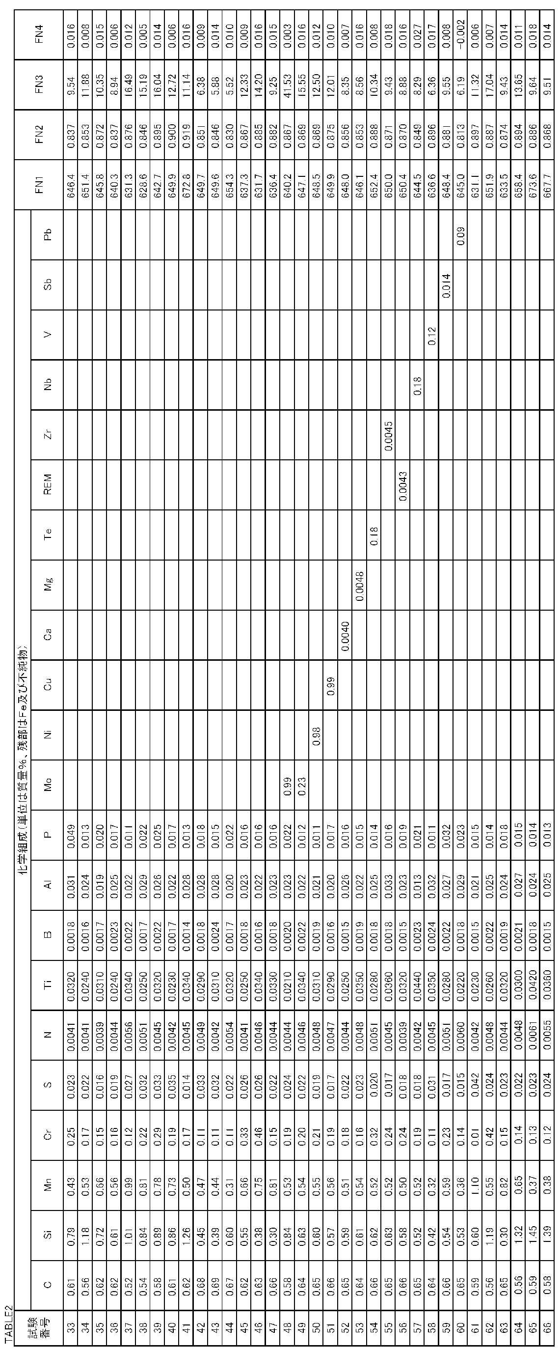
表1及び表2中の空白部分は、対応する元素の含有量が検出限界未満であったことを意味する。つまり、空白部分は、対応する元素含有量の最小桁において、検出限界未満であったことを意味する。たとえば、表1中のCu含有量の場合、最小桁は小数第2位である。したがって、試験番号1のMo含有量は、小数第2位までの桁数において、検出されなかった(有効数字が小数第2位までの含有量において、0%であった)ことを意味する。
製造されたインゴットに対して、熱間圧延(粗圧延工程及び仕上げ圧延工程)を実施して、中間鋼材(棒鋼)を製造した。粗圧延鋼材での加熱温度はいずれも1100~1300℃の範囲内であった。また、仕上げ圧延工程での加熱温度はいずれも1200~1250℃の範囲内であった。さらに、仕上げ圧延温度は900~1100℃の範囲内であった。さらに、試験番号64及び65においては、熱間圧延後の中間鋼材に対してさらに、熱間鍛造(熱間鍛伸)を実施し、熱間鍛造後の中間鋼材を放冷した(表3及び表4中の「熱間鍛造」欄において「実施」と記載)。なお、試験番号1~63では、熱間圧延後に熱間鍛造を実施することなく放冷した。以上の工程により、直径が30~100mmの棒鋼(中間鋼材)を製造した。
試験番号1~61、64及び65の中間鋼材に対して、焼準処理を実施した。具体的には、これらの試験番号の中間鋼材を熱処理炉(焼準炉)に装入して、850℃で1時間保持した。保持後の中間鋼材に対して、空冷、油冷又は水冷を実施した。700~300℃での平均冷却速度CRは表3及び表4に示すとおりであった(表3及び表4中の「平均冷却速度CR(℃/秒)」欄に記載)。なお、試験番号62及び63では、焼準処理を実施しなかった。

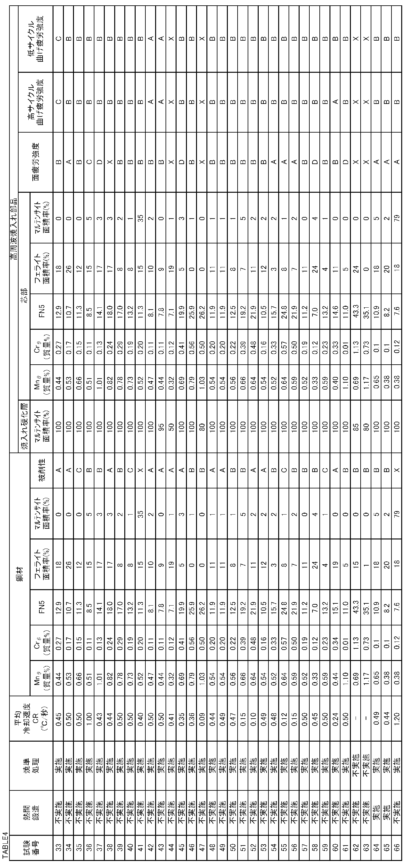
以上の製造工程により、各試験番号の鋼材(棒鋼)を製造した。
[評価試験]
[鋼材の評価試験について]
[セメンタイト中のMn濃度Mnθ及びCr濃度Crθ測定試験]
各試験番号の鋼材中のセメンタイト中のMn濃度Mnθ及びCr濃度Crθを次の方法で求めた。各試験番号の鋼材の任意の位置から、試験片を採取した。試験片に対して、10%AA系電解液を用いて、定電流電気分解を実施した。定電流電解後、メッシュサイズ0.2μmのフィルターで吸引ろ過して残渣を採取した。採取した残渣に対して、酸分解処理を実施した。酸分解処理後、ICP-AES(高周波誘導結合プラズマ原子分光分析)を実施して、残渣中のFe、Cr、Mnの質量を測定した。このとき、残渣は全てM3C型の炭化物、つまり、セメンタイトであると仮定した。得られた残渣中のFe質量、Cr質量、及びMn質量に基づいて、セメンタイトを100質量%とした場合の、セメンタイト中に固溶しているMn濃度Mnθ(質量%)、及び、Cr濃度Crθ(質量%)を算出した。得られたMn濃度Mnθを表3及び表4中の「鋼材」欄の「Mnθ(質量%)」欄に示す。得られたCr濃度Crθを表3及び表4中の「鋼材」欄の「Crθ(質量%)」欄に示す。
[鋼材の評価試験について]
[セメンタイト中のMn濃度Mnθ及びCr濃度Crθ測定試験]
各試験番号の鋼材中のセメンタイト中のMn濃度Mnθ及びCr濃度Crθを次の方法で求めた。各試験番号の鋼材の任意の位置から、試験片を採取した。試験片に対して、10%AA系電解液を用いて、定電流電気分解を実施した。定電流電解後、メッシュサイズ0.2μmのフィルターで吸引ろ過して残渣を採取した。採取した残渣に対して、酸分解処理を実施した。酸分解処理後、ICP-AES(高周波誘導結合プラズマ原子分光分析)を実施して、残渣中のFe、Cr、Mnの質量を測定した。このとき、残渣は全てM3C型の炭化物、つまり、セメンタイトであると仮定した。得られた残渣中のFe質量、Cr質量、及びMn質量に基づいて、セメンタイトを100質量%とした場合の、セメンタイト中に固溶しているMn濃度Mnθ(質量%)、及び、Cr濃度Crθ(質量%)を算出した。得られたMn濃度Mnθを表3及び表4中の「鋼材」欄の「Mnθ(質量%)」欄に示す。得られたCr濃度Crθを表3及び表4中の「鋼材」欄の「Crθ(質量%)」欄に示す。
[鋼材のフェライト面積率及びマルテンサイト面積率の測定試験]
各試験番号の鋼材中のフェライト面積率(%)を次の方法で求めた。鋼材の任意の位置からミクロ組織観察用の試験片を採取した。試験片の表面のうち、鋼材の長手方向(軸方向)に垂直な断面(観察面)を研磨した。ナイタール腐食液を用いて、研磨後の観察面をエッチングした。エッチングされた観察面を400倍の光学顕微鏡で観察して、写真画像を生成した。写真画像において、上述の方法により、フェライト及びマルテンサイトを特定した。特定されたフェライトの面積率を、JIS G 0555(2003)に準拠した点算法で測定した。測定された面積率を鋼材中のフェライト面積率と定義した。得られたフェライト面積率を表3及び表4中の「鋼材」欄の「フェライト面積率(%)」欄に示す。さらに、特定されたマルテンサイトの面積率を、JIS G 0555(2003)に準拠した点算法で測定した。測定された面積率を鋼材中のマルテンサイト面積率と定義した。得られたマルテンサイト面積率を表3及び表4中の「鋼材」欄の「マルテンサイト面積率(%)」欄に示す。
各試験番号の鋼材中のフェライト面積率(%)を次の方法で求めた。鋼材の任意の位置からミクロ組織観察用の試験片を採取した。試験片の表面のうち、鋼材の長手方向(軸方向)に垂直な断面(観察面)を研磨した。ナイタール腐食液を用いて、研磨後の観察面をエッチングした。エッチングされた観察面を400倍の光学顕微鏡で観察して、写真画像を生成した。写真画像において、上述の方法により、フェライト及びマルテンサイトを特定した。特定されたフェライトの面積率を、JIS G 0555(2003)に準拠した点算法で測定した。測定された面積率を鋼材中のフェライト面積率と定義した。得られたフェライト面積率を表3及び表4中の「鋼材」欄の「フェライト面積率(%)」欄に示す。さらに、特定されたマルテンサイトの面積率を、JIS G 0555(2003)に準拠した点算法で測定した。測定された面積率を鋼材中のマルテンサイト面積率と定義した。得られたマルテンサイト面積率を表3及び表4中の「鋼材」欄の「マルテンサイト面積率(%)」欄に示す。
[被削性評価試験]
各試験番号の鋼材を用いて、被削性を評価した。まず、ドリル被削性評価のために、直径30~100mmの棒鋼の中心から試験片を作製した。試験片は円柱状であり、長さは21mmであった。試験片の長手方向は、棒鋼の長手方向と平行であった。
各試験番号の鋼材を用いて、被削性を評価した。まず、ドリル被削性評価のために、直径30~100mmの棒鋼の中心から試験片を作製した。試験片は円柱状であり、長さは21mmであった。試験片の長手方向は、棒鋼の長手方向と平行であった。
株式会社不二越製の型番SD3.0のドリルを用いて、ドリル穿孔試験を実施した。1回転当たりの送り量を0.25mmとし、1穴の穿孔深さを9mmとした。潤滑剤として、水溶性の切削油を用いた。評価指標として、累積穴深さ1000mmまで切削可能な最大切削速度VL1000を求めた。
求めた最大切削速度VL1000に応じて、次のとおり評価した。
評価A:最大切削速度VL1000が50m/分以上
評価B:最大切削速度VL1000が45m/分以上50m/分未満
評価C:最大切削速度VL1000が40m/分以上45m/分未満
評価X:最大切削速度VL1000が40m/分未満
評価A~Cの場合、被削性に優れると判断した。評価Xの場合、被削性が低いと判断した。表3及び表4中の「鋼材」欄の「被削性」欄に評価結果を示す。
評価A:最大切削速度VL1000が50m/分以上
評価B:最大切削速度VL1000が45m/分以上50m/分未満
評価C:最大切削速度VL1000が40m/分以上45m/分未満
評価X:最大切削速度VL1000が40m/分未満
評価A~Cの場合、被削性に優れると判断した。評価Xの場合、被削性が低いと判断した。表3及び表4中の「鋼材」欄の「被削性」欄に評価結果を示す。
[高周波焼入れ部品の評価試験]
[ローラーピッチング疲労試験(面疲労強度評価試験)]
高周波焼入れ部品の面疲労強度を、次の方法で評価した。各試験番号の鋼材に対して機械加工(切削加工)を実施して、図1に示す小ローラー試験片200(以下、単に試験片200という)を作製した。鋼材の直径が80mm未満である場合、試験片200の長手方向に垂直な断面の中心位置が、鋼材の長手方向に垂直な断面の中心位置となるように、試験片200を採取した。試験片200の長手方向は、鋼材の長手方向と平行であった。鋼材の直径が80mm以上である場合、試験片200の長手方向に垂直な断面の中心位置が、鋼材の長手方向に垂直な断面のうち、半径Rの中心位置(つまり、2/R位置)となるように、試験片200を採取した。試験片200の長手方向は、鋼材の長手方向と平行であった。
[ローラーピッチング疲労試験(面疲労強度評価試験)]
高周波焼入れ部品の面疲労強度を、次の方法で評価した。各試験番号の鋼材に対して機械加工(切削加工)を実施して、図1に示す小ローラー試験片200(以下、単に試験片200という)を作製した。鋼材の直径が80mm未満である場合、試験片200の長手方向に垂直な断面の中心位置が、鋼材の長手方向に垂直な断面の中心位置となるように、試験片200を採取した。試験片200の長手方向は、鋼材の長手方向と平行であった。鋼材の直径が80mm以上である場合、試験片200の長手方向に垂直な断面の中心位置が、鋼材の長手方向に垂直な断面のうち、半径Rの中心位置(つまり、2/R位置)となるように、試験片200を採取した。試験片200の長手方向は、鋼材の長手方向と平行であった。
図1中の数値は寸法を示す。図1中の「φ」は直径を意味する。つまり、「φ22」は直径が22mmであることを意味する。試験片200は円柱状であり、試験片200の長手方向の中央位置に、直径26mmの平行部を有した。試験片200の平行部以外の円柱部の直径は22mmであった。
試験片200に対して、高周波焼入れを実施した。具体的には、加熱温度1000℃とし、加熱時間を20秒とした。加熱後の試験片200を水冷した。高周波焼入れ後の試験片200に対して、150℃の焼戻し温度で1時間保持する焼戻しを実施した。以上の工程により、高周波焼入れ部品である試験片200を製造した。各試験番号ごとに、複数の高周波焼入れ部品(試験片200)を製造した。
試験片200を用いて、図2に示すローラーピッチング試験を実施して、高周波焼入れ部品の面疲労強度を評価した。具体的には、図2を参照して、試験片200に大ローラー試験片100を押し当てながら、試験片200を回転させた。大ローラー試験片100はJIS G 4053(2016)に規定のSCM722に相当する化学組成を有する鋼材を浸炭処理した後、表面研磨したものを使用した。大ローラー試験片100の半径は130mmであった。
ローラーピッチング疲労試験では、試験片200に種々のヘルツ応力の面圧で大ローラー試験片100を押し付けた。接触部での両ローラー試験片(試験片200、大ローラー試験片100)の周速方向を同一方向とし、滑り率を-40%(試験片200よりも大ローラー試験片100の方が接触部の周速が40%大きい)として回転させた。接触部に潤滑油として供給するATF(AT用潤滑油)の油温は80℃とした。大ローラー試験片100と試験片200との接触応力を3000~3300MPaとした。試験打ち切り回数を1000万回(107回)とした。試験片200にピッチングが発生せずに1000万回の回転数に達した場合、高周波焼入れ部品(試験片100)が面疲労強度に優れると評価した。具体的には、次のとおり評価した。
評価A:3300MPaの接触応力で107回の回転数に達した
評価B:3200MPaの接触応力で107回の回転数に達したが、3300MPaの接触応力では、107回の回転数に達しなかった
評価C:3100MPaの接触応力で107回の回転数に達したが、3200MPaの接触応力では、107回の回転数に達しなかった
評価D:3000MPaの接触応力で107回の回転数に達したが、3100MPaの接触応力では、107回の回転数に達しなかった
評価X:3000MPaの接触応力で107回の回転数に達しなかった
評価A~Dの場合、高周波焼入れ部品が面疲労強度に優れると判断した。評価Xの場合、高周波焼入れ部品の面疲労強度が低いと判断した。表3及び表4中の「高周波焼入れ部品」欄の「面疲労強度」欄に評価結果を示す。また、ピッチング発生の検出は試験機に備え付けてある振動計によって行い、振動検出後に両ローラー試験片の回転を停止させてピッチングの発生と回転数とを確認した。
評価A:3300MPaの接触応力で107回の回転数に達した
評価B:3200MPaの接触応力で107回の回転数に達したが、3300MPaの接触応力では、107回の回転数に達しなかった
評価C:3100MPaの接触応力で107回の回転数に達したが、3200MPaの接触応力では、107回の回転数に達しなかった
評価D:3000MPaの接触応力で107回の回転数に達したが、3100MPaの接触応力では、107回の回転数に達しなかった
評価X:3000MPaの接触応力で107回の回転数に達しなかった
評価A~Dの場合、高周波焼入れ部品が面疲労強度に優れると判断した。評価Xの場合、高周波焼入れ部品の面疲労強度が低いと判断した。表3及び表4中の「高周波焼入れ部品」欄の「面疲労強度」欄に評価結果を示す。また、ピッチング発生の検出は試験機に備え付けてある振動計によって行い、振動検出後に両ローラー試験片の回転を停止させてピッチングの発生と回転数とを確認した。
[高周波焼入れ部品の焼入れ硬化層のマルテンサイト面積率測定試験]
各試験番号の試験片200の焼入れ硬化層のマルテンサイト面積率を、次の方法で求めた。試験片200の平行部の表面から深さ0.2mm位置から、サンプルを採取した。サンプルの表面(観察面という)を鏡面に研磨した後、ナイタール腐食液に浸漬して、エッチングによる組織現出を行った。エッチングした観察面を400倍の光学顕微鏡で観察して、写真画像を生成した。観察面のうち、任意の3視野を観察した。各視野の面積は130μm×260μmとした。各視野において、マルテンサイト、フェライト、パーライト等の各相は、コントラストから区別できる。具体的には、ナイタール腐食液で観察面を腐食した場合、ラメラ構造を有する相をパーライトと特定できる。パーライトよりも明度が高い領域(白い領域)をフェライトと特定できる。フェライト及びパーライトよりも明度が低い領域(濃い領域)をマルテンサイトと特定できる。そこで、各視野のマルテンサイトの面積を求めた。3つの視野のマルテンサイトの総面積と、各視野の総面積とに基づいて、マルテンサイト面積率(%)を定義した。求めたマルテンサイト面積率を表3及び表4中の「高周波焼入れ部品」欄の「焼入れ硬化層」欄の「マルテンサイト面積率(%)」に示す。
各試験番号の試験片200の焼入れ硬化層のマルテンサイト面積率を、次の方法で求めた。試験片200の平行部の表面から深さ0.2mm位置から、サンプルを採取した。サンプルの表面(観察面という)を鏡面に研磨した後、ナイタール腐食液に浸漬して、エッチングによる組織現出を行った。エッチングした観察面を400倍の光学顕微鏡で観察して、写真画像を生成した。観察面のうち、任意の3視野を観察した。各視野の面積は130μm×260μmとした。各視野において、マルテンサイト、フェライト、パーライト等の各相は、コントラストから区別できる。具体的には、ナイタール腐食液で観察面を腐食した場合、ラメラ構造を有する相をパーライトと特定できる。パーライトよりも明度が高い領域(白い領域)をフェライトと特定できる。フェライト及びパーライトよりも明度が低い領域(濃い領域)をマルテンサイトと特定できる。そこで、各視野のマルテンサイトの面積を求めた。3つの視野のマルテンサイトの総面積と、各視野の総面積とに基づいて、マルテンサイト面積率(%)を定義した。求めたマルテンサイト面積率を表3及び表4中の「高周波焼入れ部品」欄の「焼入れ硬化層」欄の「マルテンサイト面積率(%)」に示す。
[高周波焼入れ部品の芯部の化学組成、フェライト面積率、セメンタイト中のMn濃度Mnθ及びCr濃度Crθの測定試験]
各試験番号の試験片200の芯部の化学組成、ミクロ組織中のフェライト面積率、セメンタイト中のMn濃度Mnθ及びCr濃度Crθは、次の方法で求めた。高周波焼入れ部品の芯部からサンプルを採取した。採取されたサンプルを用いて、周知の成分分析法を実施する。具体的には、ドリルを用いて、サンプルから切粉を生成し、その切粉を採取した。採取した切粉を酸に溶解させて溶液を得た。溶液に対して、ICP-AESを実施して、化学組成の元素分析を実施した。C含有量及びS含有量については、周知の高周波燃焼法(燃焼-赤外線吸収法)により求めた。N含有量については、周知の不活性ガス溶融-熱伝導度法を用いて求めた。測定の結果、いずれの試験番号の芯部の化学組成も、対応する試験番号の鋼材の化学組成と同じであった。
各試験番号の試験片200の芯部の化学組成、ミクロ組織中のフェライト面積率、セメンタイト中のMn濃度Mnθ及びCr濃度Crθは、次の方法で求めた。高周波焼入れ部品の芯部からサンプルを採取した。採取されたサンプルを用いて、周知の成分分析法を実施する。具体的には、ドリルを用いて、サンプルから切粉を生成し、その切粉を採取した。採取した切粉を酸に溶解させて溶液を得た。溶液に対して、ICP-AESを実施して、化学組成の元素分析を実施した。C含有量及びS含有量については、周知の高周波燃焼法(燃焼-赤外線吸収法)により求めた。N含有量については、周知の不活性ガス溶融-熱伝導度法を用いて求めた。測定の結果、いずれの試験番号の芯部の化学組成も、対応する試験番号の鋼材の化学組成と同じであった。
さらに、芯部のサンプルを用いて、上述の鋼材(棒鋼)の場合と同じ方法で、ミクロ組織中のフェライト面積率、及び、セメンタイト中のMn濃度Mnθ及びCr濃度Crθを求めた。得られたMn濃度Mnθを表3及び表4中の「高周波焼入れ部品」欄の「芯部」欄の「Mnθ(質量%)」欄に示す。得られたCr濃度Crθを表3及び表4中の「高周波焼入れ部品」欄の「芯部」欄の「Crθ(質量%)」欄に示す。得られたフェライト面積率を表3及び表4中の「高周波焼入れ部品」欄の「芯部」欄の「フェライト面積率(%)」欄に示す。
[高サイクル曲げ疲労強度及び低サイクル曲げ疲労強度評価試験]
高周波焼入れ部品の高サイクル曲げ疲労強度、及び、低サイクル曲げ疲労強度を、次の方法で評価した。各試験番号の鋼材に対して機械加工(切削加工)を実施して、図3に示す小野式回転曲げ試験片(以下、単に試験片という)を作製した。鋼材の直径が80mm未満である場合、試験片の長手方向に垂直な断面の中心位置が、鋼材の長手方向に垂直な断面の中心位置となるように、試験片を採取した。試験片の長手方向は、鋼材の長手方向と平行であった。鋼材の直径が80mm以上である場合、試験片の長手方向に垂直な断面の中心位置が、鋼材の長手方向に垂直な断面のうち、半径Rの中心位置(つまり、2/R位置)となるように、試験片を採取した。試験片の長手方向は、鋼材の長手方向と平行であった。
高周波焼入れ部品の高サイクル曲げ疲労強度、及び、低サイクル曲げ疲労強度を、次の方法で評価した。各試験番号の鋼材に対して機械加工(切削加工)を実施して、図3に示す小野式回転曲げ試験片(以下、単に試験片という)を作製した。鋼材の直径が80mm未満である場合、試験片の長手方向に垂直な断面の中心位置が、鋼材の長手方向に垂直な断面の中心位置となるように、試験片を採取した。試験片の長手方向は、鋼材の長手方向と平行であった。鋼材の直径が80mm以上である場合、試験片の長手方向に垂直な断面の中心位置が、鋼材の長手方向に垂直な断面のうち、半径Rの中心位置(つまり、2/R位置)となるように、試験片を採取した。試験片の長手方向は、鋼材の長手方向と平行であった。
図3中の数値は、寸法(mm)を意味する。なお、試験片の長手方向における中央位置に、切欠きを形成した。切欠き底での試験片の直径は9mmであった。切欠き部分の曲率半径Rは1.14mmであった。
試験片に対して、高周波焼入れを実施した。具体的には、加熱温度1000℃とし、加熱時間を5秒とした。加熱後の試験片を水冷した。高周波焼入れ後の試験片200に対して、150℃の焼戻し温度で1時間保持する焼戻しを実施した。以上の工程により、高周波焼入れ部品である試験片を製造した。各試験番号ごとに複数の試験片を製造した。
[高サイクル曲げ疲労強度評価試験]
試験片(高周波焼入れ部品)を用いて、小野式回転曲げ疲労試験(高サイクル曲げ疲労試験)を行った。具体的には、小野式回転曲げ疲労試験では、所定の曲げ応力となるよう負荷荷重を調整し、試験打ち切り回数を1000万回(1×10⁷回)とした。疲労試験片が破断せずに1000万回の回転数に達した場合、高サイクル曲げ疲労強度に優れると判断した。具体的には、次のとおり評価した。
評価A:680MPaの曲げ応力で107回の回転数に達した
評価B:665MPaの曲げ応力で107回の回転数に達したが、680MPaの曲げ応力では、107回の回転数に達しなかった
評価C:650MPaの曲げ応力で107回の回転数に達したが、665MPaの曲げ応力では、107回の回転数に達しなかった
評価X:650MPaの曲げ応力で107回の回転数に達しなかった
評価A~Cの場合、高周波焼入れ部品が高サイクル曲げ疲労強度に優れると判断した。評価Xの場合、高周波焼入れ部品の高サイクル曲げ疲労強度が低いと判断した。表3及び表4中の「高周波焼入れ部品」欄の「高サイクル曲げ疲労強度」欄に評価結果を示す。
試験片(高周波焼入れ部品)を用いて、小野式回転曲げ疲労試験(高サイクル曲げ疲労試験)を行った。具体的には、小野式回転曲げ疲労試験では、所定の曲げ応力となるよう負荷荷重を調整し、試験打ち切り回数を1000万回(1×10⁷回)とした。疲労試験片が破断せずに1000万回の回転数に達した場合、高サイクル曲げ疲労強度に優れると判断した。具体的には、次のとおり評価した。
評価A:680MPaの曲げ応力で107回の回転数に達した
評価B:665MPaの曲げ応力で107回の回転数に達したが、680MPaの曲げ応力では、107回の回転数に達しなかった
評価C:650MPaの曲げ応力で107回の回転数に達したが、665MPaの曲げ応力では、107回の回転数に達しなかった
評価X:650MPaの曲げ応力で107回の回転数に達しなかった
評価A~Cの場合、高周波焼入れ部品が高サイクル曲げ疲労強度に優れると判断した。評価Xの場合、高周波焼入れ部品の高サイクル曲げ疲労強度が低いと判断した。表3及び表4中の「高周波焼入れ部品」欄の「高サイクル曲げ疲労強度」欄に評価結果を示す。
[低サイクル曲げ疲労強度評価試験]
高サイクル曲げ疲労強度評価試験と同様に、試験片(高周波焼入れ部品)を用いて、小野式回転曲げ疲労試験(低サイクル曲げ疲労試験)を行った。具体的には、小野式回転曲げ疲労試験では、所定の曲げ応力となるよう負荷荷重を調整し、試験打ち切り回数を1万回(1×10⁴回)とした。疲労試験片が破断せずに1万回の回転数に達した場合、高サイクル曲げ疲労強度に優れると判断した。具体的には、次のとおり評価した。
評価A:850MPaの曲げ応力で104回の回転数に達した
評価B:825MPaの曲げ応力で104回の回転数に達したが、850MPaの曲げ応力では、107回の回転数に達しなかった
評価C:800MPaの曲げ応力で104回の回転数に達したが、825MPaの曲げ応力では、107回の回転数に達しなかった
評価X:800MPaの曲げ応力で104回の回転数に達しなかった
評価A~Cの場合、高周波焼入れ部品が低サイクル曲げ疲労強度に優れると判断した。評価Xの場合、高周波焼入れ部品の低サイクル曲げ疲労強度が低いと判断した。表3及び表4中の「高周波焼入れ部品」欄の「低サイクル曲げ疲労強度」欄に評価結果を示す。
高サイクル曲げ疲労強度評価試験と同様に、試験片(高周波焼入れ部品)を用いて、小野式回転曲げ疲労試験(低サイクル曲げ疲労試験)を行った。具体的には、小野式回転曲げ疲労試験では、所定の曲げ応力となるよう負荷荷重を調整し、試験打ち切り回数を1万回(1×10⁴回)とした。疲労試験片が破断せずに1万回の回転数に達した場合、高サイクル曲げ疲労強度に優れると判断した。具体的には、次のとおり評価した。
評価A:850MPaの曲げ応力で104回の回転数に達した
評価B:825MPaの曲げ応力で104回の回転数に達したが、850MPaの曲げ応力では、107回の回転数に達しなかった
評価C:800MPaの曲げ応力で104回の回転数に達したが、825MPaの曲げ応力では、107回の回転数に達しなかった
評価X:800MPaの曲げ応力で104回の回転数に達しなかった
評価A~Cの場合、高周波焼入れ部品が低サイクル曲げ疲労強度に優れると判断した。評価Xの場合、高周波焼入れ部品の低サイクル曲げ疲労強度が低いと判断した。表3及び表4中の「高周波焼入れ部品」欄の「低サイクル曲げ疲労強度」欄に評価結果を示す。
[試験結果]
試験結果を表3及び表4に示す。
試験結果を表3及び表4に示す。
表1~表4を参照して、試験番号2、3、6~8、10、13、14、17、18、22、25、26、29、30、33~37、39、40、42、43、45、46、48~61では、化学組成が適切であり、FN1~FN4は式(1)~式(4)を満たした。そのため、各試験番号の鋼材の被削性は高かった。さらに、製造条件が適切であったため、鋼材のFN5が式(5)を満たし、フェライト面積率が40%以下であった。そのため、鋼材を高周波焼入れして製造された高周波焼入れ部品では、面疲労強度、高サイクル曲げ疲労強度及び低サイクル曲げ疲労強度に優れた。なお、これらの試験番号の鋼材を高周波焼入れして製造された高周波焼入れ部品において、焼入れ硬化層のマルテンサイト面積率は90%以上であった。さらに、芯部のFN5は式(5)を満たし、フェライト面積率は40%以下であった。
一方、試験番号1では、C含有量が高すぎた。そのため、被削性が低かった。さらに、高周波焼入れを実施したとき、焼割れが発生した。そのため、鋼材の被削性の評価試験、及び、高周波焼入れ部品の面疲労強度、高サイクル曲げ疲労強度及び低サイクル及び曲げ疲労強度の評価試験を実施しなかった(表3及び表4の該当する試験項目欄において「-」と表記。)。
試験番号4では、C含有量が低すぎた。そのため、鋼材を高周波焼入れして製造した高周波焼入れ部品において、面疲労強度、高サイクル曲げ疲労強度及び低サイクル曲げ疲労強度が低かった。
試験番号5では、Si含有量が高すぎた。そのため、鋼材を高周波焼入れして製造した高周波焼入れ部品において、面疲労強度、高サイクル曲げ疲労強度及び低サイクル及び曲げ疲労強度が低かった。
試験番号9では、Mn含有量が低すぎた。そのため、熱間加工時に割れが発生した。そのため、鋼材の被削性の評価試験、及び、高周波焼入れ部品の面疲労強度、高サイクル曲げ疲労強度及び低サイクル及び曲げ疲労強度の評価試験を実施しなかった(表3及び表4の該当する試験項目欄において「-」と表記。)。
試験番号11では、Cr含有量を含有しなかった。そのため、熱間加工時に割れが発生した。そのため、鋼材の被削性の評価試験、及び、高周波焼入れ部品の面疲労強度、高サイクル曲げ疲労強度及び低サイクル及び曲げ疲労強度の評価試験を実施しなかった(表3及び表4の該当する試験項目欄において「-」と表記。)。
試験番号12では、S含有量が高すぎた。そのため、高周波焼入れ部品の高サイクル曲げ疲労強度及び低サイクル曲げ疲労強度が低かった。
試験番号15では、S含有量が低すぎた。そのため、鋼材の被削性が低かった。
試験番号16では、B含有量が低すぎた。そのため、高周波焼入れ部品の低サイクル曲げ疲労強度が低かった。
試験番号19では、B含有量が高すぎた。そのため、熱間加工時に割れが発生した。そのため、鋼材の被削性の評価試験、及び、高周波焼入れ部品の面疲労強度、高サイクル曲げ疲労強度及び低サイクル及び曲げ疲労強度の評価試験を実施しなかった(表3及び表4の該当する試験項目欄において「-」と表記。)。
試験番号20では、N含有量が高すぎた。そのため、熱間加工時に割れが発生した。そのため、鋼材の被削性の評価試験、及び、高周波焼入れ部品の面疲労強度、高サイクル曲げ疲労強度及び低サイクル及び曲げ疲労強度の評価試験を実施しなかった(表3及び表4の該当する試験項目欄において「-」と表記。)。
試験番号21では、FN4が式(4)を満たさなかった。そのため、高周波焼入れ部品の低サイクル曲げ疲労強度が低かった。
試験番号23では、N含有量が低すぎた。そのため、高周波焼入れ部品の高サイクル曲げ疲労強度及び低サイクル曲げ疲労強度が低かった。
試験番号24では、Ti含有量が高すぎた。そのため、熱間加工時に割れが発生した。そのため、鋼材の被削性の評価試験、及び、高周波焼入れ部品の面疲労強度、高サイクル曲げ疲労強度及び低サイクル及び曲げ疲労強度の評価試験を実施しなかった(表3の該当する試験項目欄において「-」と表記。)。
試験番号27では、Ti含有量が低すぎた。そのため、式(4)を満たさなかった。そのため、高周波焼入れ部品の低サイクル曲げ疲労強度が低かった。
試験番号28では、Al含有量が高すぎた。そのため、高周波焼入れ部品の面疲労強度、高サイクル曲げ疲労強度及び低サイクル曲げ疲労強度が低かった。
試験番号31では、Al含有量が低すぎた。そのため、高周波焼入れ部品の高サイクル曲げ疲労強度及び低サイクル曲げ疲労強度が低かった。
試験番号32では、P含有量が高すぎた。そのため、高周波焼入れ部品の高サイクル曲げ疲労強度及び低サイクル曲げ疲労強度が低かった。
試験番号38では、FN1が式(1)の下限未満であった。そのため、高周波焼入れ部品の面疲労強度が低かった。
試験番号41では、FN2が式(2)の上限を超えた。そのため、鋼材中のマルテンサイト面積率が10%を超えた。そのため、鋼材の被削性が低かった。
試験番号44では、FN3が式(3)の下限未満であった。そのため、高周波焼入れ部品の面疲労強度及び高サイクル曲げ疲労強度及び低サイクル曲げ疲労強度が低かった。
試験番号47では、焼準処理での平均冷却速度CRが遅すぎた。そのため、鋼材において、FN5が式(5)を満たさなかった。その結果、高周波焼入れ部品の面疲労強度、高サイクル曲げ疲労強度及び低サイクル曲げ疲労強度が低かった。
試験番号62及び63では、焼準処理を実施しなかった。そのため、鋼材において、FN5が式(5)を満たさなかった。その結果、高周波焼入れ部品の面疲労強度、高サイクル曲げ疲労強度及び低サイクル曲げ疲労強度が低かった。
試験番号66では、焼準処理での平均冷却速度CRが速すぎた。そのため、鋼材中のマルテンサイト面積率が10%を超えた。そのため、鋼材の被削性が低かった。
以上、本発明の実施形態を説明した。しかしながら、上記した実施形態は本発明を実施するための例示に過ぎない。したがって、本発明は上記した実施形態に限定されることなく、その趣旨を逸脱しない範囲内で上記した実施形態を適宜変更して実施することができる。
100 大ローラー試験片
200 試験片
200 試験片
Claims (12)
- 化学組成が、質量%で、
C:0.40~0.70%、
Si:0.15~2.10%、
Mn:0.30~1.15%、
Cr:0.01~0.50%未満、
S:0.005~0.070%、
N:0.0020~0.0200%、
Ti:0.0080~0.2000%、
B:0.0005~0.0050%、
Al:0.005~0.100%、及び、
P:0.050%未満、を含有し、
残部がFe及び不純物からなり、式(1)~式(5)を満たし、
フェライト面積率が40%以下であり、マルテンサイト面積率が10%以下である、
鋼材。
290C+50Si+430≧631.0 (1)
C+(1/7)Si+(1/5)Mn+(1/9)Cr+V+(1/25)Mo≦0.900 (2)
(1+0.7Si)×(1+3.3333Mn)×(1+2.16Cr)×(1+3.00Mo)×(1+1.73V)×(1+0.365Cu)×(1+0.363Ni)×(2.616-1.6C)≧5.80 (3)
Ti-4×N≧0 (4)
9.7Mnθ+32.4Crθ≦25.9 (5)
ここで、式(1)~式(4)中の各元素記号には、対応する元素の含有量(質量%)が代入され、対応する元素が含有されていない場合、元素記号には「0」が代入され、式(5)中のMnθにはセメンタイト中のMnの濃度(質量%)が代入され、式(5)中のCrθにはセメンタイト中のCrの濃度(質量%)が代入される。 - 請求項1に記載の鋼材であって、
前記化学組成はさらに、Feの一部に代えて、
Mo:1.00%以下、
Ni:1.00%以下、及び、
Cu:1.00%以下、からなる群から選択される1種以上を含有する、
鋼材。 - 請求項1又は請求項2に記載の鋼材であって、
前記化学組成はさらに、Feの一部に代えて、
Ca:0.0050%以下、
Mg:0.0050%以下、
Te:0.20%以下、及び、
希土類元素:0.0050%以下、からなる群から選択される1種以上を含有する、
鋼材。 - 請求項1~請求項3のいずれか1項に記載の鋼材であって、
前記化学組成はさらに、Feの一部に代えて、
Zr:0.0050%以下、
Nb:0.20%以下、及び、
V:0.35%以下、からなる群から選択される1種以上を含有する、
鋼材。 - 請求項1~請求項4のいずれか1項に記載の鋼材であって、
前記化学組成はさらに、Feの一部に代えて、
Sb:0.015%以下、を含有する、
鋼材。 - 請求項1~請求項5のいずれか1項に記載の鋼材であって、
前記化学組成はさらに、Feの一部に代えて、
Pb:0.09%以下、を含有する、
鋼材。 - 焼入れ硬化層と、
前記焼入れ硬化層よりも内部の芯部と、
を備え、
前記焼入れ硬化層は、
マルテンサイト面積率が90%以上であり、
前記芯部は、
化学組成が、質量%で、
C:0.40~0.70%、
Si:0.15~2.10%、
Mn:0.30~1.15%、
Cr:0.01~0.50%未満、
S:0.005~0.070%、
N:0.0020~0.0200%、
Ti:0.0080~0.2000%、
B:0.0005~0.0050%、
Al:0.005~0.100%、及び、
P:0.050%未満、を含有し、
残部がFe及び不純物からなり、式(1)~式(5)を満たし、
フェライト面積率が40%以下であり、マルテンサイト面積率が10%以下である、
部品。
290C+50Si+430≧631.0 (1)
C+(1/7)Si+(1/5)Mn+(1/9)Cr+V+(1/25)Mo≦0.900 (2)
(1+0.7Si)×(1+3.3333Mn)×(1+2.16Cr)×(1+3.00Mo)×(1+1.73V)×(1+0.365Cu)×(1+0.363Ni)×(2.616-1.6C)≧5.80 (3)
Ti-4×N≧0 (4)
9.7Mnθ+32.4Crθ≦25.9 (5)
ここで、式(1)~式(4)中の各元素記号には、対応する元素の含有量(質量%)が代入され、式(5)中のMnθにはセメンタイト中のMnの濃度(質量%)が代入され、式(5)中のCrθにはセメンタイト中のCrの濃度(質量%)が代入される。 - 請求項7に記載の部品であって、
前記化学組成はさらに、Feの一部に代えて、
Mo:1.00%以下、
Ni:1.00%以下、及び、
Cu:1.00%以下、からなる群から選択される1種以上を含有する、
部品。 - 請求項7又は請求項8に記載の部品であって、
前記化学組成はさらに、Feの一部に代えて、
Ca:0.0050%以下、
Mg:0.0050%以下、
Te:0.20%以下、及び、
希土類元素:0.0050%以下、からなる群から選択される1種以上を含有する、
部品。 - 請求項7~請求項9のいずれか1項に記載の高周波焼入れ部品であって、
前記化学組成はさらに、Feの一部に代えて、
Zr:0.0050%以下、
Nb:0.20%以下、及び、
V:0.35%以下、からなる群から選択される1種以上を含有する、
部品。 - 請求項7~請求項10のいずれか1項に記載の部品であって、
前記化学組成はさらに、Feの一部に代えて、
Sb:0.015%以下、を含有する、
部品。 - 請求項7~請求項11のいずれか1項に記載の部品であって、
前記化学組成はさらに、Feの一部に代えて、
Pb:0.09%以下、を含有する、
部品。
Priority Applications (3)
| Application Number | Priority Date | Filing Date | Title |
|---|---|---|---|
| JP2020568160A JP7099553B2 (ja) | 2019-01-21 | 2020-01-21 | 鋼材及び部品 |
| CN202080009859.2A CN113316651B (zh) | 2019-01-21 | 2020-01-21 | 钢材及部件 |
| US17/423,964 US12006557B2 (en) | 2019-01-21 | 2020-01-21 | Steel material and component |
Applications Claiming Priority (2)
| Application Number | Priority Date | Filing Date | Title |
|---|---|---|---|
| JP2019-007949 | 2019-01-21 | ||
| JP2019007949 | 2019-01-21 |
Publications (1)
| Publication Number | Publication Date |
|---|---|
| WO2020153361A1 true WO2020153361A1 (ja) | 2020-07-30 |
Family
ID=71736804
Family Applications (1)
| Application Number | Title | Priority Date | Filing Date |
|---|---|---|---|
| PCT/JP2020/001966 Ceased WO2020153361A1 (ja) | 2019-01-21 | 2020-01-21 | 鋼材及び部品 |
Country Status (4)
| Country | Link |
|---|---|
| US (1) | US12006557B2 (ja) |
| JP (1) | JP7099553B2 (ja) |
| CN (1) | CN113316651B (ja) |
| WO (1) | WO2020153361A1 (ja) |
Cited By (2)
| Publication number | Priority date | Publication date | Assignee | Title |
|---|---|---|---|---|
| CN111876688A (zh) * | 2020-08-12 | 2020-11-03 | 宝武集团鄂城钢铁有限公司 | 一种高氮含硫易切削钢的冶炼方法 |
| JPWO2024127969A1 (ja) * | 2022-12-14 | 2024-06-20 |
Citations (4)
| Publication number | Priority date | Publication date | Assignee | Title |
|---|---|---|---|---|
| JP2001181791A (ja) * | 1999-12-24 | 2001-07-03 | Nippon Steel Corp | 高周波焼入れ性と冷鍛性に優れた冷間鍛造用棒線材 |
| WO2013183648A1 (ja) * | 2012-06-08 | 2013-12-12 | 新日鐵住金株式会社 | 鋼線材又は棒鋼 |
| WO2015076384A1 (ja) * | 2013-11-22 | 2015-05-28 | 新日鐵住金株式会社 | 高炭素鋼板及びその製造方法 |
| JP2017048440A (ja) * | 2015-09-04 | 2017-03-09 | 新日鐵住金株式会社 | 被削性に優れた機械構造部材用鋼管とその製造方法 |
Family Cites Families (5)
| Publication number | Priority date | Publication date | Assignee | Title |
|---|---|---|---|---|
| JP2004156071A (ja) | 2002-11-01 | 2004-06-03 | Sumitomo Metal Ind Ltd | 高周波焼入れ用成形部品および軸受け部品 |
| JP4581966B2 (ja) | 2005-11-08 | 2010-11-17 | 住友金属工業株式会社 | 高周波焼入れ用鋼材 |
| JP4828321B2 (ja) | 2006-06-16 | 2011-11-30 | 新日本製鐵株式会社 | 低サイクル疲労特性に優れた高周波焼入れ鋼材及び高周波焼入れ部品 |
| US10793937B2 (en) | 2014-02-24 | 2020-10-06 | Nippon Steel Corporation | Steel for induction hardening |
| US20190300994A1 (en) | 2016-07-19 | 2019-10-03 | Nippon Steel & Sumitomo Metal Corporation | Steel for Induction Hardening |
-
2020
- 2020-01-21 JP JP2020568160A patent/JP7099553B2/ja active Active
- 2020-01-21 WO PCT/JP2020/001966 patent/WO2020153361A1/ja not_active Ceased
- 2020-01-21 US US17/423,964 patent/US12006557B2/en active Active
- 2020-01-21 CN CN202080009859.2A patent/CN113316651B/zh active Active
Patent Citations (4)
| Publication number | Priority date | Publication date | Assignee | Title |
|---|---|---|---|---|
| JP2001181791A (ja) * | 1999-12-24 | 2001-07-03 | Nippon Steel Corp | 高周波焼入れ性と冷鍛性に優れた冷間鍛造用棒線材 |
| WO2013183648A1 (ja) * | 2012-06-08 | 2013-12-12 | 新日鐵住金株式会社 | 鋼線材又は棒鋼 |
| WO2015076384A1 (ja) * | 2013-11-22 | 2015-05-28 | 新日鐵住金株式会社 | 高炭素鋼板及びその製造方法 |
| JP2017048440A (ja) * | 2015-09-04 | 2017-03-09 | 新日鐵住金株式会社 | 被削性に優れた機械構造部材用鋼管とその製造方法 |
Cited By (3)
| Publication number | Priority date | Publication date | Assignee | Title |
|---|---|---|---|---|
| CN111876688A (zh) * | 2020-08-12 | 2020-11-03 | 宝武集团鄂城钢铁有限公司 | 一种高氮含硫易切削钢的冶炼方法 |
| JPWO2024127969A1 (ja) * | 2022-12-14 | 2024-06-20 | ||
| WO2024127969A1 (ja) * | 2022-12-14 | 2024-06-20 | 日本製鉄株式会社 | クランクシャフト及びクランクシャフトの製造方法 |
Also Published As
| Publication number | Publication date |
|---|---|
| JP7099553B2 (ja) | 2022-07-12 |
| CN113316651B (zh) | 2023-06-20 |
| US20220145416A1 (en) | 2022-05-12 |
| CN113316651A (zh) | 2021-08-27 |
| JPWO2020153361A1 (ja) | 2021-11-11 |
| US12006557B2 (en) | 2024-06-11 |
Similar Documents
| Publication | Publication Date | Title |
|---|---|---|
| JP7095117B2 (ja) | 浸炭窒化軸受部品 | |
| JP7095116B2 (ja) | 浸炭窒化軸受部品の素材となる鋼材 | |
| WO2012053541A1 (ja) | 冷鍛窒化用鋼、冷鍛窒化用鋼材および冷鍛窒化部品 | |
| US9200354B2 (en) | Rolled steel bar or wire for hot forging | |
| WO2013140869A1 (ja) | 窒化用鋼材および窒化部品 | |
| KR101552449B1 (ko) | 열간 단조용 압연 봉강 또는 선재 | |
| CN109477179B (zh) | 高频淬火用钢 | |
| WO2018016502A1 (ja) | 高周波焼入れ用鋼 | |
| JPWO2020145325A1 (ja) | 鋼材 | |
| WO2018016504A1 (ja) | 高周波焼入れ用鋼 | |
| JP2018199838A (ja) | 浸炭部品 | |
| JP7099553B2 (ja) | 鋼材及び部品 | |
| JP7099549B2 (ja) | 鋼材 | |
| JP2017133052A (ja) | 浸炭時の粗大粒防止特性と疲労特性と被削性に優れた肌焼鋼およびその製造方法 | |
| JP7368724B2 (ja) | 浸炭鋼部品用鋼材 | |
| JP7013833B2 (ja) | 浸炭部品 | |
| JP7139692B2 (ja) | 高周波焼入れ用鋼、高周波焼入れ部品の素形材及び高周波焼入れ部品 | |
| JP7417059B2 (ja) | 高周波焼入れ窒化処理用鋼および高周波焼入れ窒化処理部品 | |
| JP2018199837A (ja) | 浸炭部品 | |
| JP7368723B2 (ja) | 浸炭鋼部品用鋼材 | |
| JP2019183211A (ja) | 浸炭部品 | |
| JP7230651B2 (ja) | 窒化用鋼板 | |
| JP7269522B2 (ja) | 鋼材 | |
| JP7156021B2 (ja) | 浸炭鋼部品用鋼材 | |
| JP7063071B2 (ja) | 浸炭部品 |
Legal Events
| Date | Code | Title | Description |
|---|---|---|---|
| 121 | Ep: the epo has been informed by wipo that ep was designated in this application |
Ref document number: 20745530 Country of ref document: EP Kind code of ref document: A1 |
|
| ENP | Entry into the national phase |
Ref document number: 2020568160 Country of ref document: JP Kind code of ref document: A |
|
| NENP | Non-entry into the national phase |
Ref country code: DE |
|
| 122 | Ep: pct application non-entry in european phase |
Ref document number: 20745530 Country of ref document: EP Kind code of ref document: A1 |