WO2020153227A1 - ラベル付き樹脂成形品、ラベル付き樹脂成形品の製造方法、及びラベル - Google Patents
ラベル付き樹脂成形品、ラベル付き樹脂成形品の製造方法、及びラベル Download PDFInfo
- Publication number
- WO2020153227A1 WO2020153227A1 PCT/JP2020/001289 JP2020001289W WO2020153227A1 WO 2020153227 A1 WO2020153227 A1 WO 2020153227A1 JP 2020001289 W JP2020001289 W JP 2020001289W WO 2020153227 A1 WO2020153227 A1 WO 2020153227A1
- Authority
- WO
- WIPO (PCT)
- Prior art keywords
- label
- resin molded
- molded product
- surface portion
- adhesive layer
- Prior art date
- Legal status (The legal status is an assumption and is not a legal conclusion. Google has not performed a legal analysis and makes no representation as to the accuracy of the status listed.)
- Ceased
Links
Images
Classifications
-
- G—PHYSICS
- G09—EDUCATION; CRYPTOGRAPHY; DISPLAY; ADVERTISING; SEALS
- G09F—DISPLAYING; ADVERTISING; SIGNS; LABELS OR NAME-PLATES; SEALS
- G09F3/00—Labels, tag tickets, or similar identification or indication means; Seals; Postage or like stamps
- G09F3/02—Forms or constructions
-
- G—PHYSICS
- G09—EDUCATION; CRYPTOGRAPHY; DISPLAY; ADVERTISING; SEALS
- G09F—DISPLAYING; ADVERTISING; SIGNS; LABELS OR NAME-PLATES; SEALS
- G09F3/00—Labels, tag tickets, or similar identification or indication means; Seals; Postage or like stamps
- G09F3/08—Fastening or securing by means not forming part of the material of the label itself
- G09F3/10—Fastening or securing by means not forming part of the material of the label itself by an adhesive layer
-
- G—PHYSICS
- G09—EDUCATION; CRYPTOGRAPHY; DISPLAY; ADVERTISING; SEALS
- G09F—DISPLAYING; ADVERTISING; SIGNS; LABELS OR NAME-PLATES; SEALS
- G09F3/00—Labels, tag tickets, or similar identification or indication means; Seals; Postage or like stamps
- G09F3/02—Forms or constructions
- G09F2003/0201—Label sheets intended to be introduced in a printer, e.g. laser printer
-
- G—PHYSICS
- G09—EDUCATION; CRYPTOGRAPHY; DISPLAY; ADVERTISING; SEALS
- G09F—DISPLAYING; ADVERTISING; SIGNS; LABELS OR NAME-PLATES; SEALS
- G09F3/00—Labels, tag tickets, or similar identification or indication means; Seals; Postage or like stamps
- G09F3/02—Forms or constructions
- G09F2003/0202—Forms or constructions printed before use
-
- G—PHYSICS
- G09—EDUCATION; CRYPTOGRAPHY; DISPLAY; ADVERTISING; SEALS
- G09F—DISPLAYING; ADVERTISING; SIGNS; LABELS OR NAME-PLATES; SEALS
- G09F3/00—Labels, tag tickets, or similar identification or indication means; Seals; Postage or like stamps
- G09F3/02—Forms or constructions
- G09F2003/023—Adhesive
-
- G—PHYSICS
- G09—EDUCATION; CRYPTOGRAPHY; DISPLAY; ADVERTISING; SEALS
- G09F—DISPLAYING; ADVERTISING; SIGNS; LABELS OR NAME-PLATES; SEALS
- G09F3/00—Labels, tag tickets, or similar identification or indication means; Seals; Postage or like stamps
- G09F3/02—Forms or constructions
- G09F2003/0272—Labels for containers
- G09F2003/0273—Labels for bottles, flasks
Definitions
- the present invention relates to a resin molded product such as a bottle-shaped container to which a label is attached and a manufacturing method thereof.
- the present invention also relates to a label used for application to the surface of a resin molded product.
- a label and a resin are preliminarily inserted into a mold, and a resin molded product such as a container is molded by injection molding, hollow molding, differential pressure molding, foam molding or the like in the mold.
- a technique for integrating a molded product is known.
- a method for molding such a labeled resin molded product is called in-mold molding.
- Patent Document 2 a technique of previously providing print information to the porous layer of this label has been proposed (Patent Document 2). That is, when the label can be peeled from the resin molded product, if printing information can appear on the peeled surface (exposed surface) of both the resin molded product and the label, this information can be used for various purposes. Is. For example, it is possible to identify the resin molded product from which the label has been peeled off from the print information and prevent reuse or forgery of the resin molded product.
- the peeled label can be secondarily used as a coupon ticket or the like.
- a colorless ink composition is mainly filled in the porous layer of the label, so that the label becomes a resin molded product when the label is peeled from the resin molded product.
- Print information is to appear on both release surfaces of the label.
- the print information cannot be visually recognized from the appearance when the label is attached to the resin molded product, and can be visually recognized only after the label is peeled off.
- such a restriction works, but if print information is given to the label, there is also a demand for checking the print information even when the label is attached to the resin molded product. For example, when it is necessary to inform the consumer of cautions, product information, etc.
- the printing information attached to the label it is preferable that the printing information can be visually recognized before the label is peeled off. Further, for example, in the case of anti-counterfeiting of the resin molded product, a total of 3 of the label surface attached to the resin molded product, the peeled surface of the resin molded product after peeling the label, and the peeled surface of the label itself are included. If the same or corresponding print information is given to each place, the forgery prevention effect can be further enhanced.
- the label for in-mold molding described in Patent Document 1 requires a special treatment of filling the porous layer of the label with a colorless ink composition in order to give the printing information, and thus the printing processing cost.
- a normal label needs to be printed with colored ink on the front side of the product information, but if different printing information is given with a colorless ink to the porous layer corresponding to the back side, Since it is necessary to perform double-sided printing on one label using different inks, there is a problem that the number of printing steps increases and the cost increases.
- the inventors of the present invention have earnestly studied about the means for solving the problems of the above conventional invention, and as a result, performed pretreatment for partially reducing the cross-sectional porosity of a label including a porous base layer and an adhesive layer. Later, it was found that by integrating the label with the resin molded product by in-mold molding, the surface roughness of the pretreated portion becomes smoother than the other portions. By utilizing the above phenomenon, it is possible to give the label visible information from the appearance by utilizing the difference in surface roughness between the pre-treated portion of the label and the other portion. Then, the inventors have completed the present invention based on the idea that the problems of the conventional invention can be solved based on the above findings. Hereinafter, the configuration and process of the present invention will be described in detail.
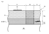
- the first aspect of the present invention relates to a resin molded product 20 to which the label 10 is attached.
- the label 10 has a multilayer structure in which a layer including a porous base layer (A) and an adhesive layer (B) attached to the surface of the resin molded product 20 is laminated.
- the label 10 attached to the resin molded product 20 is formed with a rough surface portion 11 having a relatively rough surface roughness and a smooth surface portion 12 having a predetermined pattern 12a having a relatively smooth surface roughness.
- the cross-section porosity of the label 10 in the rough surface portion 11 is 100%
- the cross-section porosity of the label 10 in the smooth surface portion 12 is 0 to 93%.
- the cross-sectional porosity of the label 10 can be reduced, and the reduced porosity portion has a relatively smooth surface roughness.
- the smooth surface portion 12 is formed.
- the portion of the label 10 having a high cross-section porosity becomes the rough surface portion 11 having a rough surface roughness due to the influence of the fine voids contained therein.
- information of a predetermined pattern can be provided on the surface of the label 10 without using ink.
- the smooth surface portion 12 does not have fine voids therein, or even if it does exist, the size or number is smaller than that of the rough surface portion 11.
- the smooth surface portion 12 is a portion where the physical structure of at least the porous base layer (A) is different from that of the rough surface portion 11, the pattern represented by the smooth surface portion 12 is visible from the surface side of the label 10. is there. Therefore, even when the label 10 is still attached to the resin molded product 20, the pattern of the smooth surface portion 12 can be visually recognized from the appearance. In particular, by setting the cross-section porosity of the label 10 in the smooth surface portion 12 to 0 to 93% with respect to the rough surface portion 11, the pattern of the smooth surface portion 12 becomes noticeable so that it can be easily visually recognized.
- the surface roughness of the rough surface portion 11 (ten-point average roughness in particular) and Rz r
- the surface roughness of the smooth surface portion 12 was Rz a
- the smooth surface portion 12 is preferably formed by heating and pressurizing the label 10 from the front surface side or the back surface side thereof before sticking the label 10 to the resin molded product. ..
- the porosity of the label 10 can be easily locally reduced, and the partial smooth surface portion 12 can be easily formed.
- the adhesive layer (B) may include a porous adhesive layer (B1).
- the porous adhesive layer (B1) when the label 10 is peeled from the resin molded article 20 by dividing the porous adhesive layer (B1), the peeled surface of the peeled portion 10a of the label peeled from the resin molded article 20 and the resin molded article It is preferable that the patterns 12b and 12c corresponding to the smooth surface portion 12 respectively appear on the peeling surface of the remaining portion 10b of the label that remains on 20.
- the peeling surface means the surface exposed by peeling the label 10.
- the smooth surface portion 12 of the label is a portion where the cross-sectional porosity of both the porous base layer (A) and the porous adhesive layer (B1) is reduced. Therefore, even when the label 10 is divided in the porous adhesive layer (B1), the smooth surface portions 12 are present on both the peeling surface of the peeling portion 10a and the peeling surface of the residual portion 10b of the label. Therefore, the patterns 12b and 12c corresponding to the smooth surface portion 12 respectively appear on both the peeled portion 10a and the remaining portion 10b of the label.
- the pattern of the residual portion 10b is the same as the pattern of the smooth surface portion 12, but the pattern 12b of the peeled portion 10a has a mirror image symmetry of the pattern of the smooth surface portion 12.
- the label 10 surface in the state of being adhered to the resin molded product 20, the peeled surface of the resin molded product 20 after the label 10 is peeled off, and the peeled surface of the label 10 itself, in total, are the same or respectively. Since the corresponding information can be added, it is possible to more effectively prevent, for example, reuse or forgery of the resin molded product 20.
- the adhesive layer (B) may include a heat seal layer (B2) having no pores in the layer.
- the adhesive layer (B) may include both the porous adhesive layer (B1) and the heat seal layer (B2). In this case, either the porous adhesive layer (B1) or the heat seal layer (B2) may be used as the surface to which the resin molded article 20 is attached.
- the second aspect of the present invention relates to a method for manufacturing the resin molded product 20 to which the label 10 is attached.
- the label 10 is formed by laminating a layer including a porous base layer (A) and an adhesive layer (B) attached to the surface of the resin molded product 20.
- the manufacturing method according to the present invention includes a hot press step and an in-mold step.
- the hot pressing step is a step of forming a hot pressing portion 12' having a predetermined pattern by heating and pressing the label 10 from the front surface side or the back surface side.
- the in-molding step is a step of inserting the label 10 having the hot-pressed portion 12 ′ into the mold and integrating it with the resin molded product 20 in the mold.
- the rough surface portion 11 having a relatively rough surface roughness and the surface roughness corresponding to the pattern of the hot press portion 12 ′ are relatively smooth.
- the surface portion 12 is formed. According to this manufacturing method, the labeled resin molded article according to the first aspect can be efficiently manufactured.
- the surface roughness of the non-hot press portion 11 ′ (that is, the area corresponding to the rough surface portion 11) other than the hot press portion 12 ′ of the label 10 becomes rough after the in-molding process. That is, the label 10 has almost no difference in surface roughness between the hot-pressed portion 12 ′ and the other non-hot-pressed portion 11 ′ after the hot-pressing step.
- the surface roughness of the non-hot pressed portion 11' becomes rough due to the in-mold process.
- the imitation product manufactured in such a manner has the rough surface portion 11 as the regular product. Since the difference in surface roughness of the smooth surface portion 12 does not occur, it is difficult to visually recognize the pattern of the smooth surface portion 12. On the other hand, the rough surface portion 11 of the label 10 becomes rough and the pattern of the smooth surface portion 12 is raised only when the label 10 is integrated with the resin molded product 20 through the regular in-mold process. Therefore, if the state of the label 10 is confirmed, it is possible to easily distinguish between the genuine product and the imitation product.
- the third aspect of the present invention mainly relates to a label used for application to the resin molded product 20.
- the label 10 according to the present invention has a multilayer structure in which layers including a porous base layer (A) and an adhesive layer (B) are laminated.
- the label 10 has a first portion 11' having a relatively high cross-section porosity and a second portion 12' having a relatively low cross-section porosity.
- the cross-sectional porosity of the label in the second part 12' is 0 to 93% of the cross-sectional porosity of the label in the first part 11'.
- the present invention it is possible to provide information to a label without using ink, and to provide a resin molded product with a label that allows the information to be visually recognized from the appearance even when the label is attached. You can
- FIG. 1 schematically shows a cross-sectional structure of a labeled resin molded article according to the first embodiment.
- FIG. 2 shows a state where the label is attached to the resin molded product (FIG. 2A) and a state where the label is peeled off from the resin molded product (FIG. 2) for the labeled resin molded product according to the first embodiment. 2(b)) is shown.
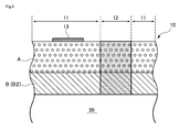
- FIG. 3 schematically shows a cross-sectional structure of a labeled resin molded product according to the second embodiment.
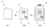
- FIG. 4 schematically shows a manufacturing process of a labeled resin molded product.
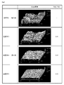
- FIG. 5 shows the surface roughness of the labeled resin molded products according to the example and the comparative example.
- First Embodiment 1 and 2 show a first embodiment of a labeled resin molded product according to the present invention.
- the label 10 is attached to the surface of the resin molded product 20.
- the label 10 has the resin molded product 20 attached thereto by in-mold molding.
- the resin molded product 20 is not particularly limited, and various known objects such as known oil containers, chemical containers, and food containers can be used.
- the label 10 has a structure in which a porous base layer (A) and an adhesive layer (B) are laminated.
- the adhesive layer (B) is a layer adhered to the resin molded product 20, and the porous base layer (A) is laminated on the adhesive layer (B). Any printing can be performed on the porous base layer (A) using the known ink composition 13.
- the adhesive layer (B) is formed of the porous adhesive layer (B1).
- the label 10 has a rough surface portion 11 having a relatively rough surface and a smooth surface portion 12 having a relatively smooth surface. Therefore, when the resin molded product 20 to which the label 10 is attached is viewed from the surface side, the pattern of the smooth surface portion 12 (surface pattern 12a) is formed on the rough surface portion 11 due to the difference in surface roughness between the rough surface portion 11 and the smooth surface portion 12. ) Appears to rise. Specifically, since the rough surface portion 11 and the smooth surface portion 12 have different light reflectances, the pattern of the smooth surface portion 12 is visually recognized.
- the ratio of the rough surface portion 11 to the entire surface of the label 10 is increased and the ratio of the smooth surface portion 12 is decreased so that the pattern of the smooth surface portion 12 is formed in the rough surface portion 11.
- the surface is formed, on the contrary, it is possible to decrease the ratio of the rough surface portion 11 and increase the ratio of the smooth surface portion 12.
- the ink composition 13 for printing is not limited to the rough surface portion 11 and can be attached to the smooth surface portion 12.
- the label 10 can be peeled from the resin molded product 20 as shown in FIG. 2B from the state where the label 10 is attached to the resin molded product 20. At that time, the label 10 is divided in the porous adhesive layer (B1) to be separated into a peeled portion 10a separated from the resin molded product 20 and a residual portion 10b remaining on the surface of the resin molded product 20. That is, as shown in FIG. 1, when the label 10 is peeled from the resin molded product 20, a cut is made in the end face of the porous adhesive layer (B1), and the cut is enlarged, so that the porous adhesive layer (B1) is divided into two in the thickness direction. Therefore, the peeled portion 10a of the label 10 includes the porous base layer (A) and the porous adhesive layer (B1), and the remaining portion 10b of the label 10 is composed of only the porous adhesive layer (B1). ..
- the pattern (surface pattern) of the smooth surface portion 12 that appears on the surface of the label 10 in the state of being adhered to the resin molded product 20 is also present on the peeled portion 10a and the residual portion 10b after peeling the label 10.
- the pattern corresponding to 12a) appears. That is, on the peeled surface of the peeled portion 10a of the label 10 (the surface exposed by peeling of the label 10), the mirror image pattern 12b that is a mirror image target of the surface pattern 12a appears, and on the peeled surface of the remaining portion 10b of the label 10, The same pattern 12c as the surface pattern 12a appears.
- the mirror image pattern 12b of the peeled portion 10a and the same pattern 12c of the remaining portion 10b have relatively smooth surface roughness as compared with other portions. , A specific pattern appears due to the difference in surface roughness.
- the porosity of the porous base layer (A) and the porous adhesive layer (B1) of the label 10 is reduced, and the site where the porosity is reduced Results in a smooth surface portion 12 having a relatively rough surface.
- a site having a low porosity also in the porous adhesive layer (B1) that is divided when the label 10 is peeled off when the porous adhesive layer (B1) is divided into two parts. Then, a pattern corresponding to the pattern of the smooth surface portion 12 appears on the peeled surface.
- the configuration of the label 10 having the above characteristics will be described in detail below.
- the porous base layer (A) is a layer containing a thermoplastic resin and having a large number of fine voids having a filler core. That is, when a thermoplastic resin film containing a filler is stretched, fine voids are generated inside the film. Further, since the porous base layer (A) contains a thermoplastic resin, the label 10 can be imparted with mechanical strength such as stiffness, water resistance, chemical resistance, and opacity as required.
- the strength of the porous base layer (A) is higher than that of the porous adhesive layer (B1), and when the label 10 is peeled off by gripping the porous base layer (A), It has strength that does not break.
- the cohesive force (peel strength or tensile strength at break) of the porous base layer (A) itself is preferably 200 gf/15 mm or more.
- thermoplastic resin used in the porous base layer (A) is not particularly limited, and examples thereof include polyolefin resins such as polyethylene resins, polypropylene resins, polybutene, and 4-methyl-1-pentene (co)polymers; ethylene- Vinyl acetate copolymer, ethylene-(meth)acrylic acid copolymer, metal salt of ethylene-(meth)acrylic acid copolymer (ionomer), ethylene-(meth)acrylic acid alkyl ester copolymer (of alkyl group Functional group-containing olefinic resins such as maleic acid-modified polyethylene, maleic acid-modified polypropylene, etc.; aromatic polyesters (polyethylene terephthalate, polybutylene terephthalate, polyethylene naphthalate, etc.), aliphatics Polyester resin such as polyester (polybutylene succinate, polylactic acid, etc.); Polyamide resin such as nylon-6, nylon-6,6, nylon
- thermoplastic resin forming the porous base layer (A) it is preferable to use a polyolefin resin or a polyester resin as the thermoplastic resin forming the porous base layer (A) because it has high water resistance and transparency and can easily form a resin film.
- polypropylene resin is more preferable among polyolefin resins, and polyethylene terephthalate is more preferable among polyester resins.
- the effect of the present invention is remarkable when a polyolefin resin is used.
- polypropylene resin examples include isotactic homopolypropylene obtained by homopolymerizing propylene, syndiotactic homopolypropylene, propylene as a main component, ethylene, 1-butene, 1-pentene, 1-hexene, 4-methyl- Examples thereof include polypropylene-based copolymers having various stereoregularities obtained by copolymerizing ⁇ -olefins such as 1-pentene, 1-heptene and 1-octene.
- the polypropylene-based copolymer may be a binary system or a ternary or higher ternary system, and may be a random copolymer or a block copolymer.
- the porous base layer (A) contains a filler for forming a large number of fine voids inside the thermoplastic resin.
- the filler include inorganic fillers and organic fillers, which can be used alone or in combination.
- the thermoplastic resin film containing the filler is stretched, a large number of fine pores having the filler as a core are formed inside the thermoplastic resin film.
- the rigidity, whiteness and opacity of the porous base layer (A) may be adjusted by the filler.
- the inorganic filler examples include heavy calcium carbonate, light calcium carbonate, calcined clay, talc, diatomaceous earth, titanium oxide, zinc oxide, barium sulfate, silicon oxide, magnesium oxide, fatty acids, polymer surfactants and antistatic agents. Inorganic particles which have been surface-treated with the like. Of these, heavy calcium carbonate, light calcium carbonate, calcined clay or talc are preferable because they have good void formability and are inexpensive. From the viewpoint of improving whiteness and opacity, titanium oxide, zinc oxide or barium sulfate is preferable.
- the organic filler is not particularly limited, but organic particles that are incompatible with the thermoplastic resin, have a higher melting point or glass transition temperature than the thermoplastic resin, and are finely dispersed under the melt-kneading condition of the thermoplastic resin are preferable.
- thermoplastic resin is a polyolefin resin
- organic filler polyethylene terephthalate, polybutylene terephthalate, polyethylene naphthalate, polystyrene, polyamide, polycarbonate, polyethylene sulfide, polyphenylene sulfide, polyimide, polyether ketone, polyether ether ketone
- organic particles such as polymethyl methacrylate, poly-4-methyl-1-pentene, homopolymers of cyclic olefins, and copolymers of cyclic olefins and ethylene.
- thermosetting resin such as melamine resin
- the melting point (°C) and glass transition temperature (°C) of the resin can be measured by differential scanning calorimetry (DSC).
- the inorganic filler and the organic filler may be used alone by selecting one from the above, or may be used in combination of two or more. When two or more kinds are combined, a combination of an inorganic filler and an organic filler may be used.
- the average particle size of the inorganic filler and the organic filler is preferably large from the viewpoint of easy mixing with the thermoplastic resin. Further, the average particle diameter of the inorganic filler and the organic filler, when generating voids inside by stretching to improve opacity and printability, troubles such as sheet breakage during stretching and strength reduction of the porous base layer. From the viewpoint of making it difficult to generate, it is preferably small. Specifically, the average particle size of the inorganic filler and the organic filler is preferably 0.01 ⁇ m or more, more preferably 0.1 ⁇ m or more, and further preferably 0.5 ⁇ m or more. Further, it is preferably 30 ⁇ m or less, more preferably 20 ⁇ m or less, and further preferably 15 ⁇ m or less.
- the average particle diameter of the inorganic filler and the organic filler is the average value when the maximum diameter of at least 10 particles of the thermoplastic resin film is observed by observing the cut surface of the thermoplastic resin with an electron microscope, and the thermoplastic resin is obtained by melt-kneading and dispersing. It can be obtained as the average dispersed particle diameter when dispersed in the medium.
- the content of the filler in the porous base layer is preferably 1% by mass or more, more preferably 3% by mass or more, and further preferably 5% by mass or more in order to generate desired voids in the layer. From the viewpoint of imparting rigidity to the label and improving handleability, the content of the filler in the porous base layer is preferably 45% by mass or less, more preferably 40% by mass or less, and further preferably 35% by mass or less. Is.
- the porous adhesive layer (B1) is a layer having a large number of fine voids that open to the surface and is mainly used for binding with the resin molded product 20. That is, when the label 10 and the resin molded product 20 are integrated by in-mold molding, the resin pressure during the molding of the resin molded product 20 causes the molten resin of the resin molded product 20 to enter the voids on the surface of the porous adhesive layer (B1). The label 10 and the resin molded product 20 are bound by the anchoring effect when they enter. Therefore, the label 10 can be attached to the resin molded product 20 regardless of the material of the resin molded product 20.
- the porous adhesive layer (B1) is a layer that is more brittle and weaker in strength than the porous base layer (A). Therefore, when the label 10 is peeled off from the resin molded article 20 by pulling the porous base layer (A), the porous adhesive layer (B1) is easily cohesively destroyed. Thereby, the porous base layer (A) can be easily peeled off from the resin molded product 20. Since the porous adhesive layer (B1) has a large number of communicating voids inside, when the label 10 is attached to the resin molded product 20, air remains between the label 10 and the resin molded product 20. However, this air is pushed out by the resin through the voids of the porous adhesive layer (B1) and is discharged to the outside. Therefore, the label 10 does not swell due to the air remaining between the resin molded products 20.
- the material of the porous adhesive layer (B1) is not particularly limited, but it is preferable to use a stretched resin film containing a blend of a crystalline polypropylene resin and a thermoplastic resin and a filler. In particular, it is preferable to use a thermoplastic resin that is incompatible with the crystalline polypropylene resin. As described above, the peeling of the label 10 is performed by the cohesive failure of the porous adhesive layer (B1). For that purpose, at least two kinds of resins which are incompatible with each other are used as the resin material forming the porous adhesive layer (B1), and the blended resin is stretched in a phase-separated state and stretched to form the porous adhesive layer. (B1) is formed.
- Crystallinity of the crystalline polypropylene resin is more preferably 66% or more, and particularly preferably 67-80%.
- the degree of crystallinity is 65% or more, the compatibility between the amorphous part of the crystalline polypropylene resin and the thermoplastic resin does not easily proceed, and the desired interfacial peeling effect is easily obtained, and the stress required for peeling (peeling strength ) Can be appropriately reduced.
- the crystallinity is 80% or less, it is easy to obtain commercially.
- Thermoplastic resins that are incompatible with crystalline polypropylene resin include polyethylene resin, styrene resin, cyclic polyolefin resin, ethylene-cyclic olefin copolymer resin, propylene- ⁇ olefin copolymer resin, nylon-6, nylon-6,6. , Nylon-6,10, nylon-6,12 and other polyamide resins, polyethylene terephthalate and its copolymers, polyethylene naphthalate, polybutylene terephthalate, polybutylene succinate, polylactic acid, aliphatic polyester and other thermoplastic polyesters Examples include resin and polycarbonate. These may be used as a mixture of two or more.
- polyethylene resin is preferably used from the viewpoint of chemical resistance, production cost, and the like. Due to the presence of the incompatible thermoplastic resin, interfacial peeling occurs between the crystalline polypropylene resin and the polypropylene resin incompatible thermoplastic resin during the production of the stretched film to improve the peelability. When the amount of the incompatible thermoplastic resin is 105 to 300 parts by weight with respect to 100 parts by weight of the polypropylene resin, it is easy to obtain sufficient peelability.
- "incompatible” has a morphology of a sea-island structure, when a blend of a crystalline polypropylene resin and an incompatible thermoplastic resin is observed with an electron microscope, and its structure Indicates that the dimension is 0.3 to 10 ⁇ m.
- an inorganic filler and/or an organic filler can be used as the filler contained in the porous adhesive layer (B1).
- the filler of the porous adhesive layer (B1) one whose surface is hydrophilized with a surface treatment agent may be adopted.
- a surface treatment agent for example, when the porous adhesive layer (B1) is formed using a hydrophilically treated inorganic filler, interfacial peeling between the inorganic filler and the crystalline polypropylene easily occurs in the porous adhesive layer (B1). It becomes easier to peel from the resin molded product 20.
- Patent Document 2 those described in Patent Document 2 (WO/2017/188298) may be referred to.
- the content of the blend of the crystalline polypropylene resin and the incompatible thermoplastic resin is preferably 30 to 60% by weight, and 35 to 50% by weight based on 100% by weight of the entire porous adhesive layer (B1). % Is more preferable.
- the content of the filler in the porous adhesive layer (B1) is preferably 40 to 70% by weight, more preferably 50 to 65% by weight. When the content of the filler in the porous adhesive layer (B1) is 40% by weight or more, sufficient peelability can be easily obtained. Further, when it is 70% by weight or less, molding stability is easily obtained.
- the blending ratio of the thermoplastic resin incompatible with the crystalline polypropylene resin is preferably 105 to 300 parts by weight, and 120 to 280 parts by weight with respect to 100 parts by weight of the crystalline polypropylene resin. It is more preferable that the amount is 140 to 270 parts by weight, and it is further preferable.
- the surface of the label 10 attached to the resin molded product 20 is visibly divided into a rough surface portion 11 (a portion having a relatively rough surface) and a smooth surface portion 12 (having a relatively rough surface). Has been done. Therefore, for example, by forming the predetermined surface pattern 12a by the smooth surface portion 12, it is possible to present information to consumers and the like. It is also possible to present information by patterning the rough surface portion 11.
- the surface roughness of the rough surface portion 11 and Rz r In a state where the label 10 to the resin molded article 20 is adhered (see FIG. 2 (a)), the surface roughness of the rough surface portion 11 and Rz r, the surface roughness of the smooth surface 12 when the Rz a, It is preferable that Rz r is 25 ⁇ m or more, and Rz a /Rz r is less than 0.6.
- Rz r is 25 ⁇ m or more
- Rz a /Rz r is less than 0.6.
- the surface roughness Rz r of the rough surface portion 11 is preferably 30 ⁇ m or more or 35 ⁇ m or more, and particularly preferably 40 ⁇ m or more or 50 ⁇ m or more.
- the upper limit of the surface roughness Rz r of the rough surface portion 11 is not particularly limited, but it may be 150 ⁇ m or less or 100 ⁇ m or less in consideration of beautifully printing the product information and the like on the label 10 using the ink composition 13. It is preferably 80 ⁇ m or less, and particularly preferably 80 ⁇ m or less.
- the surface roughness Rz a synovial surface portion 12 is preferably 30 ⁇ m or less, or 25 ⁇ m or less, particularly preferably 15 or less.
- the surface roughness Rz a of the smooth surface portion 12 is preferably 5 to 30 ⁇ m or 10 to 25 ⁇ m. Further, the smaller the ratio (Rz a /Rz r ) of the surface roughness of the rough surface portion 11 and the smooth surface portion 12 becomes, the more distinct the difference between the two becomes. For this reason, the surface roughness ratio (Rz a /Rz r ) is preferably 0.5 or less, more preferably 0.45 or less, or more preferably 0.4 or less, and 0.35 or 0.3. The following is particularly preferable.
- surface roughness means ten-point average roughness (Rz) unless otherwise specified.
- the surface roughness is measured by the following method. Using a non-contact three-dimensional surface shape roughness measuring device (NewView5010, manufactured by Zygo Co., Ltd.), measurement area: 2 mm ⁇ 2 mm, objective lens: 20 times, measurement is performed by cutting a wavelength of 14 ⁇ m or less, The ten-point average roughness Rz ( ⁇ m) obtained by analysis using analysis software (manufactured by Zygo Corp.: Metro Pro) is defined as the surface roughness.
- the label sticking surface of the resin molded product has a curved shape, cut out the label stuck part of the resin molded product to make a sample, and test the sample with double-sided tape so that the label part is the upper surface. It is fixed on a table and the surface roughness is measured under the above conditions.
- the rough surface portion 11 and the smooth surface portion 12 of the label 10 are classified into, for example, a hot press process (heating and pressurizing process; hot stamping process) corresponding to a desired pattern of the smooth surface portion 12 on the base paper of the label 10.
- a hot press process heating and pressurizing process; hot stamping process
- the label 10 can be made to appear by adhering the label 10 to the resin molded product 20 by in-mold molding. That is, regarding the label 10 after the hot press treatment, there is almost no difference in surface roughness between the portion subjected to the hot press treatment and the other portions.
- the surface roughness of the portion not subjected to hot press treatment increases to become the rough surface portion 11, and the surface roughness of the portion subjected to hot press treatment is almost the same as before. Becomes the smooth surface portion 12.
- the label 10 is divided into the rough surface portion 11 and the smooth surface portion 12 through both the hot pressing process and the in-mold forming process.
- the conditions for heating and pressurizing the portion corresponding to the smooth surface portion 12 in the hot press treatment are preferably, for example, the following conditions. That is, the pressurizing temperature is preferably 110 to 150° C., and particularly preferably 120 to 140° C. By setting the pressing temperature to 110° C. or higher, the thermoplastic resin contained in the label 10 is preferably melted, and the smooth smooth surface portion 12 can be formed. On the other hand, by suppressing the pressurization temperature to within 150° C., it is possible to prevent the resin forming the label 10 from melting and maintain the shape of the label 10, for example. Further, the pressurizing pressure is preferably 0.5 MPa or more, for example, 0.5 to 10 MPa.
- the pressurizing pressure By setting the pressurizing pressure to 0.5 MPa or more under the above temperature conditions, the size and number of fine voids contained in the porous base layer (A) and the porous adhesive layer (B1) of the label 10 are appropriately reduced. As a result, the porosity at that portion decreases. As will be described later, the difference in surface roughness between the rough surface portion 11 and the smooth surface portion 12 is caused by the difference in the porosity of that portion, but under appropriate heating and pressurizing conditions, the smooth surface portion By subjecting the portion corresponding to 12 to the hot press treatment, the difference in surface roughness between the rough surface portion 11 and the smooth surface portion 12 becomes clearer.
- the pressurizing pressure is 10 MPa or less, it is possible to prevent the label from being damaged or broken during hot pressing.
- the pressurizing time is, for example, preferably 0.05 to 1 second, and more preferably 0.1 to 0.5 second. By setting the pressing time within an appropriate range, the smooth smooth surface portion 12 can be formed without causing breakage or the like of the label.
- the cross-section porosity of the label 10 in the hot press portion (corresponding to the smooth surface portion 12) subjected to the hot press treatment is the same as that in the other non-hot press portion (corresponding to the rough surface portion 11). It becomes lower than the cross-section porosity. Then, a relatively large number of fine voids are present in the non-hot pressed portion having a high cross-section void ratio. Therefore, the non-hot press part will follow the shrinkage caused by the phase change of the material of the resin molded product from the semi-molten state to the solid state when the label 10 is attached to the resin molded product 20 by in-mold molding.
- the hot-pressed portion of the label 10 has a smooth surface roughness even after the in-mold forming, and forms the above-mentioned smooth surface portion 12. In this way, the rough surface portion 11 and the smooth surface portion 12 can be formed on the label 10 after the in-mold molding by performing the hot pressing process on the label 10 in a predetermined pattern.
- the cross-sectional porosity of the label in the hot press part is 0 to 93% when the cross-section porosity of the label in the non-hot press part (rough surface part 11) is 100%. It is preferable.
- the state in which the ratio of the cross-section porosity is 0% is a state in which there are no voids in the hot press portion. From the viewpoint of the pressurizing temperature and the pressurizing time during the hot press treatment, the ratio of the cross-section porosity is more preferably 30% or more, further preferably 50% or more, and particularly preferably 70% or more.
- the ratio of the cross-section porosity is more preferably 93% or less, further preferably 82% or less.
- the cross-sectional porosity of the label in the hot-pressed portion is set to 93% or less with respect to the non-hot-pressed portion, a wrinkle generated after the in-mold molding has a clear difference, and the rough surface portion 11 and the smooth surface portion 12 are formed.
- the surface roughness of the can be varied to the extent that it can be visually confirmed.
- the cross-sectional porosity of the label in the hot press part is individually measured, the cross-sectional porosity is preferably 0 to 31%, and 20 to 29%. It is particularly preferable that Similarly, the cross-sectional porosity of the label in the non-hot-pressed portion (rough surface portion 11) is preferably 32 to 50%, and particularly preferably 32 to 37%.
- the cross-section porosity of the label is the cross-section porosity in the thickness direction of the entire label. That is, in the present invention, the label 10 is configured to include the porous base layer (A) and the adhesive layer (B), but the cross-section porosity of each layer is not measured separately, but the entire label 10 including both layers. The cross-section porosity of is measured.
- the cross-sectional porosity of the label is obtained by taking an electron micrograph of the cross-section of the label and determining the area ratio (%) of voids (holes) in the cross-sectional area taken in the photograph.
- a sample is formed by cutting an arbitrary part from a sample of a label or a single label attached to a resin molded product, and embedding this sample in an epoxy resin to solidify it, and then using a microtome.
- a cut surface parallel to the thickness direction of the label that is, perpendicular to the surface direction
- vapor-deposit the cut surface and metallize it, and then select an arbitrary magnification (for example, 500 times) easy to observe with the electron microscope.
- the photograph taken by enlarging the image to 3,000 times) is binarized, the image is processed by the image analyzer, the area ratio (%) of the holes occupying the measurement range is obtained, and the cross section in the thickness direction of the label is obtained.
- Porosity (%) The cross-sectional porosity of the label is significantly different whether the label after being attached to the resin molded product by in-mold molding is measured or when the label before being attached to the resin molded product is measured. Does not occur. Therefore, either the label before in-mold molding or the label after in-mold molding may be used as the sample for the cross-section porosity measurement.
- FIG. 3 shows a second embodiment of the labeled resin molded product according to the present invention.
- the second embodiment is common to the first embodiment in that the label 10 is composed of the porous base layer (A) and the adhesive layer (B), but as the adhesive layer (B), Instead of the adhesive layer (B1), a heat seal layer (B2) having no holes in the layer is used.
- the first embodiment and the second embodiment are common in that the rough surface portion 11 and the smooth surface portion 12 are formed on the label 10.
- the description regarding the porous base layer (A), the rough surface portion 11, and the smooth surface portion 12 according to the first embodiment can be applied to the second embodiment.
- the heat seal layer (B2) is a layer for adhering the label 10 and the resin molded product 20.
- the heat seal layer (B2) is formed of a thermoplastic resin.
- the heat seal layer (B2) is solid at room temperature, but is activated by the heat of the molten resin for molding the resin molded product 20 in the mold during in-mold molding, is fused with the molten resin, and is cooled. After that, it becomes solid again and exhibits a strong adhesive force.
- the adhesive layer (B) has no holes in the layer.
- the thermoplastic resin constituting the heat seal layer (B2) has a melting point of 60 to 130° C. determined as a peak temperature by DSC measurement.
- the temperature is lower than 60°C, stickiness at room temperature deteriorates the slipperiness of the label, and blocking or the like is likely to occur. Therefore, when inserting the label into the mold, many problems such as inserting two labels are likely to occur. If the temperature is higher than 130° C., the adhesiveness between the label and the molded body tends to deteriorate.
- thermoplastic resin forming the heat seal layer (B2) is a polyolefin resin. More specifically, low to medium density high-pressure polyethylene, linear linear polyethylene, ethylene, ⁇ -olefin copolymer, propylene/ ⁇ -olefin photopolymer, ethylene/vinyl acetate copolymer, ethylene/acrylic Acid copolymer, ethylene/acrylic acid alkyl ester copolymer, ethylene/methacrylic acid alkyl ester copolymer (alkyl group has 1 to 8 carbon atoms), ethylene/methacrylic acid copolymer metal salt (Zn, Al , Li, K, Na, etc.) having a melting point of 60 to 130° C. can be used.
- resins may be used alone or in combination of two or more.
- other known additives for resins can be optionally added to the heat seal layer (B2) as long as the performance required for the heat seal layer is not impaired.
- additives include dyes, nucleating agents, plasticizers, release agents, antioxidants, antiblocking agents, flame retardants, ultraviolet absorbers, and dispersants.
- the label 10 is imprinted after the label 10 is hot-pressed in a predetermined pattern as in the first embodiment. It is attached to the resin molded product 20 by molding. As a result, the hot-pressed portion of the label 10 becomes the smooth surface portion 12 having a relatively rough surface, and the other portions become the rough surface portion 11 having a rough surface roughness. Therefore, the predetermined pattern of the smooth surface portion 12 of the label 10 attached to the resin molded product 20 can be visually confirmed, and thus information can be presented to the user or the like.
- the heat seal layer (B2) is divided into two parts by separating the heat seal layer (B2) when the label 10 is peeled from the resin molded product 20.
- the phenomenon of remaining on the surface of the article 20 is unlikely to occur. Therefore, when the heat seal layer (B2) is used as the adhesive layer (B), as in the case where the porous adhesive layer (B1) is used, the peeled portion 10a and the residual portion 10b of the label 10 are The phenomenon that a pattern corresponding to the smooth surface portion 12 is formed is unlikely to occur. Therefore, in this respect, the first embodiment is more advantageous than the second embodiment.
- a configuration in which a porous adhesive layer (B1) and a heat seal layer (B2) are laminated as the adhesive layer (B) can be adopted.
- the heat seal layer (B2) plays a role of reinforcing the adhesive force between the label 10 and the resin molded product 20.
- FIG. 4 schematically shows a method for producing a labeled resin molded product. The manufacturing method described here can be applied to both the first embodiment and the second embodiment.
- the base paper 10' is processed into a desired shape and size by cutting or punching.
- the label base paper 10' has a structure in which the porous base layer (A) and the adhesive layer (B) are laminated as described above, and the adhesive layer (B) includes a porous adhesive layer (B1) and a heat seal.
- the layer (B1) or a combination thereof can be used.
- the base paper 10′ may be manufactured by a known method as a method for manufacturing a laminated film, such as a coextrusion method, an extrusion laminating method, a film laminating method, and a coating method.
- the ink composition 13 is applied to the surface of the base paper 10' that has been processed into a desired shape and size on the side of the porous base layer (A) for arbitrary printing, and the front surface or the back surface of the base paper 10'.
- the hot press process is performed from the side in a predetermined pattern to form the hot press part 12' and the non-hot press part 11' (step S2). Suitable conditions for the pressurizing temperature, pressurizing pressure and pressurizing time in the hot press treatment are as described above.
- the label 10 for in-mold molding is manufactured.
- the printing process and the hot pressing process with the ink composition 13 are usually performed in different steps in different devices, but the printing process and the hot pressing process can be performed simultaneously in the same device.
- cutting or punching processing of the label base paper 10', printing processing of the base paper 10', and hot press processing may be performed in any order.
- the printing process, the hot pressing process, and the working process may be performed in this order, or the printing process, the working process, and the hot pressing process may be performed in that order, or another order may be performed.
- the label 10 manufactured in this manner has a relatively low cross-sectional porosity in the hot-pressed portion 12 ′ and a relatively high cross-sectional porosity in the non-hot-pressed portion 11 ′.
- the hot-pressed label 10 is attached to the surface of the resin molded product 20 by in-mold molding (step S3). That is, the label 10 is inserted into the mold so that the porous base layer (A) side is the inner wall surface side of the mold and the adhesive layer (B) side is in contact with the molten resin, and the label 10 is labeled by the in-mold molding method.
- Manufacture resin molded products In the in-mold molding method, a resin molded product such as a container can be molded in a mold by a known method such as injection molding, hollow molding, differential pressure molding, or foam molding.
- injection molding may be performed in which a molten resin is injected into a mold by an injection device and then cooled and solidified.
- fine wrinkles are formed on the surface of the label 10 in an attempt to follow the shrinkage of the resin molded product to which the label is attached during molding.
- the adhesive layer (B) is formed of the porous adhesive layer (B1)
- fine wrinkles are similarly formed on the porous adhesive layer (B1).
- the surface roughness becomes coarse due to the fine wrinkles on the surface.
- the hot-pressed portion 12' having a relatively low cross-section porosity is not affected as much as the non-hot-pressed portion 11', and the surface roughness is maintained relatively smooth.
- the rough surface portion 11 corresponding to the non-hot press portion 11 ′ and the smooth surface portion 12 corresponding to the hot press portion 12 ′ are formed on the label 10 attached to the resin molded product 20. Therefore, due to the difference in the surface roughness (specifically, the light reflectance) of the rough surface portion 11 and the smooth surface portion 12, for example, the predetermined pattern formed by the smooth surface portion 12 becomes visible. Various patterns can be presented to the consumer by the pattern of the smooth surface portion 12.
- the resin composition (b1) for forming the porous adhesive layer (B1) consisting of 2% by mass (point 140° C.) is melt-kneaded by an extruder set at 250° C., extruded into a sheet through a die, and the vertical uniaxial The stretched film was laminated on one side to obtain a laminate having a two-layer structure of (a1)/(b1).
- the label base paper 1 had a thickness of 105 ⁇ m and a cross-sectional porosity of 32%.
- Label production example 1 The label base paper 1 obtained in Production Example 1 of label base paper was punched into a size of 109 mm in width and 171 mm in length, and a porous base layer (A) was formed using a hot press machine (manufactured by Navitas Co., Ltd., model: V-08C). From the surface of (1), a label was produced by pressing with a mold having a predetermined pattern heated to 120° C. for 0.1 second. The height position was adjusted so that the pressure when pressurized was 1 to 5 MPa.
- Label production examples 2 to 11, 13 to 15 A label was produced in the same manner as in Example 1 except that the hot press treatment conditions were changed as shown in Table 1 in Label Production Example 1.
- Label production example 12 The label base paper 2 obtained in Production Example 2 of label base paper was punched into a size of 109 mm in width and 171 mm in length, and a porous base layer surface (using a hot press machine (manufactured by Navitas Co., Ltd., model: V-08C)) From the surface of A), pressure was applied for 0.3 seconds with a mold having a predetermined pattern heated to 130° C. to produce a label.
- a hot press machine manufactured by Navitas Co., Ltd., model: V-08C
- Label production example 16 The label base paper 3 obtained in Production Example 3 of label base paper was punched out to a size of 109 mm in width and 171 mm in length, and a porous base layer surface (using a hot press machine (manufactured by Navitas Co., Ltd., model: V-08C)) From the surface of A), pressure was applied for 0.5 seconds with a mold having a predetermined pattern heated to 140° C. to produce a label.
- a hot press machine manufactured by Navitas Co., Ltd., model: V-08C
- Examples 1 to 12 Comparative Examples 1 to 3
- a blow molding machine manufactured by Placo Co., model: V-50 type
- an automatic label feeder manufactured by Pentel Co., Ltd.
- a hollow molding split mold that can obtain a bottle container with an internal capacity of 1,000 ml
- High-density polyethylene (manufactured by Nippon Polyethylene Corporation, trade name: Novatec HD HB330, melting point: 133°C) is melt extruded at 200°C to form a parison, which is introduced between the mold halves and then the mold halves are clamped, then 4.2 kg. /Cm 2 of compressed air is supplied into the parison, and the parison is expanded to be in close contact with the mold to form a container and adhere to the label, and then the mold is cooled with cooling water at 10° C., and after about 10 seconds. The mold was opened and the hollow container molded product to which the label was attached was taken out and used as a labeled resin container (resin molded product).
- FIG. 5 shows a labeled resin container analyzed using a non-contact three-dimensional surface roughness measuring device (NewView5010, manufactured by Zygo Corp.) and its analysis software (MetroPro, manufactured by Zygo Corp.).
- NewView5010 manufactured by Zygo Corp.
- MicroPro manufactured by Zygo Corp.
- the image showing the surface roughness the image of the rough surface portion is shown as a reference example, and the images of the smooth surface portion of Comparative Example 3, Example 4, and Example 5 are shown.
- the ratio of the cross-sectional porosity of the smooth surface portion to the cross-sectional porosity of the rough surface portion is preferably 93% or less.
Landscapes
- Physics & Mathematics (AREA)
- General Physics & Mathematics (AREA)
- Engineering & Computer Science (AREA)
- Theoretical Computer Science (AREA)
- Laminated Bodies (AREA)
- Injection Moulding Of Plastics Or The Like (AREA)
- Blow-Moulding Or Thermoforming Of Plastics Or The Like (AREA)
Priority Applications (3)
| Application Number | Priority Date | Filing Date | Title |
|---|---|---|---|
| US17/290,260 US12190756B2 (en) | 2019-01-21 | 2020-01-16 | Resin formed product with label, production method of resin formed product with label, and label |
| CN202080006406.4A CN113168787B (zh) | 2019-01-21 | 2020-01-16 | 附带标签的树脂成型品、附带标签的树脂成型品的制造方法、以及标签 |
| JP2020568105A JP7362673B2 (ja) | 2019-01-21 | 2020-01-16 | ラベル付き樹脂成形品、ラベル付き樹脂成形品の製造方法、及びラベル |
Applications Claiming Priority (2)
| Application Number | Priority Date | Filing Date | Title |
|---|---|---|---|
| JP2019007516 | 2019-01-21 | ||
| JP2019-007516 | 2019-01-21 |
Publications (1)
| Publication Number | Publication Date |
|---|---|
| WO2020153227A1 true WO2020153227A1 (ja) | 2020-07-30 |
Family
ID=71736199
Family Applications (1)
| Application Number | Title | Priority Date | Filing Date |
|---|---|---|---|
| PCT/JP2020/001289 Ceased WO2020153227A1 (ja) | 2019-01-21 | 2020-01-16 | ラベル付き樹脂成形品、ラベル付き樹脂成形品の製造方法、及びラベル |
Country Status (4)
| Country | Link |
|---|---|
| US (1) | US12190756B2 (enExample) |
| JP (1) | JP7362673B2 (enExample) |
| CN (1) | CN113168787B (enExample) |
| WO (1) | WO2020153227A1 (enExample) |
Citations (3)
| Publication number | Priority date | Publication date | Assignee | Title |
|---|---|---|---|---|
| WO1998032598A1 (en) * | 1997-01-28 | 1998-07-30 | Avery Dennison Corporation | In-mold labels and uses thereof |
| JP2013195732A (ja) * | 2012-03-21 | 2013-09-30 | Fuji Seal International Inc | ラベル、及びラベルの製造方法 |
| WO2017188298A1 (ja) * | 2016-04-28 | 2017-11-02 | 株式会社ユポ・コーポレーション | ラベル付き樹脂成形品及びその製造方法 |
Family Cites Families (8)
| Publication number | Priority date | Publication date | Assignee | Title |
|---|---|---|---|---|
| US3245857A (en) * | 1962-05-15 | 1966-04-12 | Reynolds Metals Co | Method for making labeled containers |
| US3790439A (en) * | 1971-04-28 | 1974-02-05 | Minnesota Mining & Mfg | Printable, heat-bondable sheet material |
| US6946182B1 (en) * | 1999-07-16 | 2005-09-20 | Allgeuer Thomas T | Fringed surface structures obtainable in a compression molding process |
| US20050020448A1 (en) * | 2003-07-23 | 2005-01-27 | Fuji Photo Film Co., Ltd. | Paper, image-recording material support, and image-recording material |
| JP4475627B2 (ja) * | 2003-09-18 | 2010-06-09 | 株式会社フジシールインターナショナル | ラベル |
| ES2539423T3 (es) * | 2008-10-30 | 2015-06-30 | Sca Hygiene Products Ab | Artículo absorbente desechable que comprende una etiqueta impresa |
| JP5859230B2 (ja) | 2010-12-22 | 2016-02-10 | 株式会社ユポ・コーポレーション | インモールド成形用ラベル及びそれを用いたラベル付き樹脂成形品 |
| US8794724B2 (en) * | 2012-03-28 | 2014-08-05 | Masonite Corporation | Surface marked articles, related methods and systems |
-
2020
- 2020-01-16 WO PCT/JP2020/001289 patent/WO2020153227A1/ja not_active Ceased
- 2020-01-16 JP JP2020568105A patent/JP7362673B2/ja active Active
- 2020-01-16 US US17/290,260 patent/US12190756B2/en active Active
- 2020-01-16 CN CN202080006406.4A patent/CN113168787B/zh active Active
Patent Citations (3)
| Publication number | Priority date | Publication date | Assignee | Title |
|---|---|---|---|---|
| WO1998032598A1 (en) * | 1997-01-28 | 1998-07-30 | Avery Dennison Corporation | In-mold labels and uses thereof |
| JP2013195732A (ja) * | 2012-03-21 | 2013-09-30 | Fuji Seal International Inc | ラベル、及びラベルの製造方法 |
| WO2017188298A1 (ja) * | 2016-04-28 | 2017-11-02 | 株式会社ユポ・コーポレーション | ラベル付き樹脂成形品及びその製造方法 |
Also Published As
| Publication number | Publication date |
|---|---|
| CN113168787B (zh) | 2023-03-10 |
| CN113168787A (zh) | 2021-07-23 |
| JP7362673B2 (ja) | 2023-10-17 |
| US20220020296A1 (en) | 2022-01-20 |
| US12190756B2 (en) | 2025-01-07 |
| JPWO2020153227A1 (enExample) | 2020-07-30 |
Similar Documents
| Publication | Publication Date | Title |
|---|---|---|
| JP5043177B2 (ja) | インモールド成形用ラベル | |
| US9633580B2 (en) | Label for in-mold molding, in-mold molded article and method for molding same | |
| US9102126B2 (en) | Readily removable film, label for in-mold molding, molded resin article having label attached thereto, wallpaper, glue label, and container having label attached thereto | |
| KR102542086B1 (ko) | 열가소성 수지 필름 및 그 제조 방법, 인몰드 성형용 라벨 그리고 라벨이 부착된 플라스틱 용기 및 그 제조 방법 | |
| US8187692B2 (en) | In-mold label and molded article using the same | |
| JP5859230B2 (ja) | インモールド成形用ラベル及びそれを用いたラベル付き樹脂成形品 | |
| US20160046101A1 (en) | In-mold label and labeled plastic container using same | |
| CN101202002B (zh) | 具有优异的标签去除性的标签和带有该标签的容器 | |
| CN101156192B (zh) | 模内成型用标签及应用了该标签的成型品 | |
| JP5492547B2 (ja) | ラベル付き容器とその製造方法 | |
| EP1793997A1 (en) | Cavitated opaque polymer film and methods related thereto | |
| JP4799231B2 (ja) | インモールド成形用ラベル及びそれを用いた成形品 | |
| JP7362673B2 (ja) | ラベル付き樹脂成形品、ラベル付き樹脂成形品の製造方法、及びラベル | |
| CN100581930C (zh) | 带有标签的树脂容器 | |
| WO2024177134A1 (ja) | 積層体 | |
| US20240150075A1 (en) | Container with label | |
| JP2024141813A (ja) | 成形体 |
Legal Events
| Date | Code | Title | Description |
|---|---|---|---|
| 121 | Ep: the epo has been informed by wipo that ep was designated in this application |
Ref document number: 20744897 Country of ref document: EP Kind code of ref document: A1 |
|
| ENP | Entry into the national phase |
Ref document number: 2020568105 Country of ref document: JP Kind code of ref document: A |
|
| NENP | Non-entry into the national phase |
Ref country code: DE |
|
| 122 | Ep: pct application non-entry in european phase |
Ref document number: 20744897 Country of ref document: EP Kind code of ref document: A1 |