WO2020153105A1 - 受信装置、アンテナ制御方法、及び通信システム - Google Patents
受信装置、アンテナ制御方法、及び通信システム Download PDFInfo
- Publication number
- WO2020153105A1 WO2020153105A1 PCT/JP2019/051626 JP2019051626W WO2020153105A1 WO 2020153105 A1 WO2020153105 A1 WO 2020153105A1 JP 2019051626 W JP2019051626 W JP 2019051626W WO 2020153105 A1 WO2020153105 A1 WO 2020153105A1
- Authority
- WO
- WIPO (PCT)
- Prior art keywords
- antenna
- signal quality
- value
- signal
- switching
- Prior art date
- Legal status (The legal status is an assumption and is not a legal conclusion. Google has not performed a legal analysis and makes no representation as to the accuracy of the status listed.)
- Ceased
Links
Images






Classifications
-
- H—ELECTRICITY
- H04—ELECTRIC COMMUNICATION TECHNIQUE
- H04B—TRANSMISSION
- H04B7/00—Radio transmission systems, i.e. using radiation field
- H04B7/02—Diversity systems; Multi-antenna system, i.e. transmission or reception using multiple antennas
- H04B7/04—Diversity systems; Multi-antenna system, i.e. transmission or reception using multiple antennas using two or more spaced independent antennas
- H04B7/08—Diversity systems; Multi-antenna system, i.e. transmission or reception using multiple antennas using two or more spaced independent antennas at the receiving station
- H04B7/0802—Diversity systems; Multi-antenna system, i.e. transmission or reception using multiple antennas using two or more spaced independent antennas at the receiving station using antenna selection
- H04B7/0805—Diversity systems; Multi-antenna system, i.e. transmission or reception using multiple antennas using two or more spaced independent antennas at the receiving station using antenna selection with single receiver and antenna switching
- H04B7/0814—Diversity systems; Multi-antenna system, i.e. transmission or reception using multiple antennas using two or more spaced independent antennas at the receiving station using antenna selection with single receiver and antenna switching based on current reception conditions, e.g. switching to different antenna when signal level is below threshold
-
- H—ELECTRICITY
- H04—ELECTRIC COMMUNICATION TECHNIQUE
- H04W—WIRELESS COMMUNICATION NETWORKS
- H04W24/00—Supervisory, monitoring or testing arrangements
- H04W24/08—Testing, supervising or monitoring using real traffic
-
- H—ELECTRICITY
- H04—ELECTRIC COMMUNICATION TECHNIQUE
- H04B—TRANSMISSION
- H04B1/00—Details of transmission systems, not covered by a single one of groups H04B3/00 - H04B13/00; Details of transmission systems not characterised by the medium used for transmission
- H04B1/06—Receivers
- H04B1/16—Circuits
- H04B1/30—Circuits for homodyne or synchrodyne receivers
-
- H—ELECTRICITY
- H04—ELECTRIC COMMUNICATION TECHNIQUE
- H04W—WIRELESS COMMUNICATION NETWORKS
- H04W48/00—Access restriction; Network selection; Access point selection
- H04W48/16—Discovering, processing access restriction or access information
Definitions
- the present disclosure relates to a receiving device, an antenna control method, and a communication system.
- LTE Long Time Evolution
- IoT Internet of Things
- standardization and practical application of LTE communication methods applied to IoT such as the CAT-M1 method and the NB (Narrow Band)-IoT method, are being advanced.
- the present disclosure proposes a receiving device, an antenna control method, and a communication system that can respond to changes in the communication environment while suppressing power consumption.
- a reception device processes a plurality of antennas compatible with an LTE communication scheme and a reception signal acquired by any one of the plurality of antennas. And one reception processing unit.
- FIG. 1 is a diagram showing an example of a communication system according to a first embodiment of the present disclosure. It is a figure which shows the structural example of the receiving apparatus which concerns on the 1st Embodiment of this indication. It is a figure which shows an example of the measurement result of each signal quality value for every throughput according to the output level which concerns on 1st Embodiment of this indication.
- 5 is a flowchart showing a flow of antenna switching processing according to the first embodiment of the present disclosure. It is a figure which shows an example of the measurement result of the throughput corresponding to each modulation system which concerns on the 2nd Embodiment of this indication.
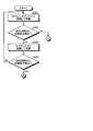
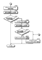
- 10 is a flowchart showing a flow of antenna switching processing according to the second embodiment of the present disclosure.
- 9 is a flowchart showing a flow of antenna switching processing according to the third embodiment of the present disclosure.
- 9 is a flowchart showing a flow of antenna switching processing according to the third embodiment of the present disclosure.
- It is a figure which shows the structural example of the smart meter which concerns on other embodiment.
- It is a hardware block diagram which shows an example of a computer which implement
- It is a figure which shows an example of a specification of a LTE communication system.
- It is a figure which shows an example of a receiving diversity structure.
- First Embodiment 1-1 Configuration of communication system according to first embodiment 1-2. Configuration of Receiving Device According to First Embodiment 1-3. Procedure of antenna switching processing according to the first embodiment 2. Second embodiment 2-1. 2. Procedure of antenna switching processing according to the second embodiment. Third embodiment 3-1. Configuration of receiving device according to third embodiment 3-2. 3. Procedure of antenna switching process according to third embodiment Other Embodiments 5. Effects of the receiving device according to the present disclosure 6. Hardware configuration
- FIG. 1 is a diagram illustrating an example of a communication system 1 according to the first embodiment of the present disclosure.
- the communication system 1 illustrated in FIG. 1 is an IoT system that uses communication using the LTE communication method (hereinafter, referred to as “LTE communication”) for IoT.
- LTE communication the LTE communication method
- the communication system 1 includes a base station 2 and an IoT device 3.
- the base station 2 is a device that transmits and receives radio signals in LTE communication.
- the IoT device 3 is a device that performs LTE communication by transmitting and receiving radio signals to and from the base station 2.
- the IoT device 3 includes a wireless communication unit 4, and the wireless communication unit 4 includes a receiving device 10.
- the receiving device 10 is a device that processes a radio signal in the LTE communication received from the base station 2.
- the receiving device 10 includes a first antenna 101 and a second antenna 102 that support LTE communication.
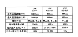
- FIG. 12 is a diagram showing an example of specifications of the LTE communication method.
- “Cat-4” shown in FIG. 12 is a specification generally used for smartphones and the like.
- “Cat-M1” and “NB-IoT” shown in FIG. 12 are specifications generally used for IoT devices.
- the specifications of the LTE communication method used for IoT devices are such that power consumption is reduced by narrowing the terminal operation bandwidth (channel bandwidth) and decreasing the maximum communication speed (transmission rate). It is a specification that is specifically designed to reduce power consumption and reduce modem complexity.
- the LTE communication system is applied to a mobile body such as an automobile telematic, it is expected that communication will be difficult with the specifications shown in FIG. 12 as the LTE communication system used for IoT devices.
- the LTE communication method is applied to a smart meter or environment monitoring in which the visibility from the base station is poor and the influence of external environment fluctuations and multipaths is large, the communication shown in FIG. 12 is difficult. Expected to become.
- FIG. 13 is a diagram illustrating a configuration example of the receiving device 30 according to the comparative example.
- the receiving device 30 according to the comparative example employs a diversity configuration using the antenna 31 and the antenna 32.
- the receiving device 30 includes an antenna 31 and an antenna 32 that receive a radio wave from the base station 2.
- the receiving device 30 has two systems including a circuit (system 1) that processes a reception signal acquired by the antenna 31 and a circuit (system 2) that processes a reception signal acquired by the antenna 32. A processing circuit is provided. Then, the receiving device 30 can select or combine appropriate reception signals from the reception signals acquired by the antenna 31 and the antenna 32.
- each antenna requires a processing circuit that processes the received signal.
- LTE communication is used for IoT devices such as smart meters that are expected to have long-term communication, it is necessary to simplify the circuit configuration of the receiving device as much as possible to reduce power consumption.
- the first embodiment of the present disclosure proposes the reception device 10 that has resistance to changes in the environment of the transmission path while suppressing power consumption.
- the configuration of the receiving device 10 according to the first embodiment will be specifically described below.
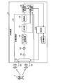
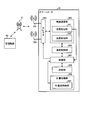
- FIG. 2 is a diagram illustrating a configuration example of the reception device 10 according to the first embodiment of the present disclosure.
- the reception device 10 includes a reception processing unit 100, a first antenna 101, a second antenna 102, a synchronization signal detection unit 109, a signal quality measurement unit 110, a storage unit 111, and a control unit 112.
- the first antenna 101 (an example of the first antenna) and the second antenna 102 (an example of the second antenna) are devices that receive radio waves compatible with the LTE communication method.
- LTE communication system a low-speed communication system equivalent to the CAT-M1 system and the NB-IoT system is exemplified.
- the first antenna 101 and the second antenna 102 obtain a reception signal by converting the electric wave received from the base station 2 into an electric signal.
- the first antenna 101 and the second antenna 102 input the acquired received signal to the receiving device 10.
- the receiving device 10 When the power is turned on, the receiving device 10 is connected to either the first antenna 101 or the second antenna 102 and stands by.
- the reception processing unit 100 connected to the first antenna 101 and the second antenna 102 includes a selector 103, an amplifier 104, a mixer 105, a baseband processing unit 106, a conversion unit 107, and a demodulation unit 108.
- the reception processing unit 100 processes a reception signal acquired by the first antenna 101 or the second antenna 102.
- the reception processing unit 100 includes one selector 103, one amplifier 104, one mixer 105, one baseband processing unit 106, one conversion unit 107, and one demodulation unit 108 for each of the first antenna 101 and the second antenna 102. It is composed of a processing circuit of.
- the selector 103 switches to either the first antenna 101 or the second antenna 102 according to the control signal of the control unit 112.
- the baseband processing unit 106 converts the reception signal acquired via the amplifier 104 and the mixer 105 into a baseband signal.
- the baseband processing unit 106 may convert the radio signal amplified by the amplifier 104 and frequency-converted by the mixer 105 into a baseband signal.
- the baseband processing unit 106 directly converts the radio signal into a baseband signal by a direct conversion method. May be converted to
- the conversion unit 107 converts a baseband signal that is an analog signal into a baseband signal that is a digital signal.
- the demodulation unit 108 executes demodulation processing of a downlink signal from the base station 2 to the receiving device 10. That is, the demodulation unit 108 demodulates the baseband signal converted into the digital signal, using a predetermined modulation method, on the modulation symbol of the channel of the down ring signal. Examples of the predetermined modulation method include QPSK (Quadrature Phase shift Keying), 16QAM (Quadrature Amplitude Modulation), and the like.
- QPSK Quadrature Phase shift Keying
- 16QAM Quadrature Amplitude Modulation
- the synchronization signal detection unit 109 detects a cell in the network at an initial stage before the LTE communication is started, and detects a synchronization signal at the time of initial cell search executed to establish synchronization with the base station 2.
- the initial cell search is composed of a primary (initial) synchronization sequence using a primary synchronization signal (PSS: Primary Synchronization Signal) and a secondary synchronization sequence using a secondary synchronization signal (SSS: secondary Synchronization Signal).
- the signal quality measurement unit 110 measures the quality of the received signal when the synchronization signal is detected by the synchronization signal detection unit 109 described later and a predetermined communication is started. Specifically, the signal quality measurement unit 110 uses the detection of the synchronization signal at the time of initial cell search by the synchronization signal detection unit 109 as a trigger, and the quality of the received signal acquired by the antenna used at the time of initial cell search. A signal quality value indicating is calculated. The signal quality measuring unit 110 outputs the calculated signal quality value to the control unit 112.
- the signal quality measurement unit 110 calculates a signal quality value based on the analog signal acquired from the baseband processing unit 106 or the digital signal acquired from the conversion unit 107.
- the signal quality measuring unit 110 can calculate a signal quality value based on a calculation result using, for example, an RSSI (Received Signal Strength Indicator) value. Further, the signal quality measuring unit 110 can calculate the signal quality value based on the calculation result using the RSRP (Reference Signal Received Power) value. Further, the signal quality measuring unit 110 can calculate the signal quality value based on the calculation result using the RSRQ (Reference Signal Received Quality) value. Further, the signal quality measuring unit 110 can calculate the signal quality value based on the calculation result using the SINR (Signal to Interference plus Noise Ratio) value.
- SINR Signal to Interference plus Noise Ratio
- the signal quality measurement unit 110 can also calculate the signal quality value based on the calculation result using at least one of the RSSI value, the RSRP value, the RSRQ value, and the SINR value.
- the signal quality measurement unit 110 may calculate at least one of a value related to the RSSI value, a value related to the RSRP value, a value related to the RSRQ value, and a value related to the SINR value as an operation result. Based on that, the signal quality value can be calculated.
- the RSRP value, the RSRQ value, the SINR value, and the RSSI value exemplified as the index of the signal quality value are merely examples, and other indexes may be used.
- the signal quality measuring unit 110 receives a control signal instructing remeasurement of the signal quality value from the control unit 112, the signal quality value is calculated again.
- the signal quality measuring unit 110 outputs the recalculated signal quality value to the control unit 112.
- the storage unit 111 stores programs and data used for control by the control unit 112.
- the storage unit 111 is realized by, for example, a RAM, a semiconductor memory device such as a flash memory, or a storage device such as a hard disk or an optical disk.
- the storage unit 111 can store, for example, a predetermined threshold value that the control unit 112 compares with the signal quality value calculated by the signal quality measuring unit 110.
- FIG. 3 is a diagram showing an example of the measurement result of each signal quality value for each throughput according to the output level according to the first embodiment of the present disclosure.
- the throughput was almost flat during the output level on the transmission side from “ ⁇ 52 (dbm)” to “ ⁇ 58 (dbm)”. Then, when the output level of the transmitting side falls below “ ⁇ 60 (dbm)”, the throughput also starts to decrease, and the throughput corresponding to the output level of the transmitting side of “ ⁇ 62 (dbm)” is “ ⁇ 60 (dbm)”. It decreased to 23.76%, which is about one-third of the above. Then, the throughput corresponding to the output level on the transmitting side of "-66 (dbm)" was 0%. Further, as the output level on the transmission side decreased, all the signal quality values of the RSRP value, RSRQ value, SINR value, and RSSI value generally decreased.
- a predetermined threshold for antenna switching can be set according to the throughput required by the IoT device 3. For example, if the throughput required by the IoT device 3 is about 20%, the predetermined threshold value corresponding to the RSRP value can be set to "-133". Similarly, if the throughput required by the IoT device 3 is about 20%, the threshold value corresponding to the RSRQ value can be set to "-30". Similarly, if the throughput required by the IoT device 3 is about 20%, the predetermined threshold value corresponding to the SINR value can be set to "-11". Similarly, if the throughput required by the IoT device 3 is about 20%, the predetermined threshold value corresponding to the RSSI value can be set to “ ⁇ 102”.
- the control unit 112 controls each unit of the receiving device 10.
- the control by the control unit 112 is realized by, for example, a CPU, an MPU, or the like executing a program stored in the receiving device 10 (for example, a program recorded in the storage unit 111) using a RAM or the like as a work area. It Further, the control by the control unit 112 may be realized by, for example, an integrated circuit such as ASIC or FPGA.
- the control unit 112 arbitrarily selects either the first antenna 101 or the second antenna 102 as the antenna at the start of the initial cell search, and selects the selected antenna. Connect to and wait. Subsequently, when the synchronization signal detection unit 109 detects a synchronization signal at the time of initial cell search, the control unit 112 starts predetermined communication, and the signal quality value acquired from the signal quality measurement unit 110 is less than a predetermined threshold value. Or not.
- the control unit 112 outputs an antenna switching signal to the selector 103 when the signal quality value acquired from the signal quality measuring unit 110 is less than a predetermined threshold value. For example, when the control unit 112 is connected to the first antenna 101 at the start of the initial cell search, the control unit 112 outputs a switching signal requesting switching from the first antenna 101 to the second antenna 102 to the selector 103.
- control unit 112 does not switch the antenna when the signal quality value is equal to or higher than a predetermined threshold value.
- the receiving device 10 continues communication using the currently connected antenna.
- the control unit 112 After the switching of the antennas is executed, the control unit 112 outputs a control signal instructing re-measurement of the signal quality value to the signal quality measuring unit 110. Then, the control unit 112 compares the signal quality value after antenna switching acquired from the signal quality measuring unit 110 with the signal quality value before antenna switching. When the signal quality value after antenna switching is smaller than the signal quality value before antenna switching, the control unit 112 outputs the antenna switching signal to the selector 103 again, and switches the antenna. When the signal quality value measured after switching to the second antenna 102 is smaller than the signal quality value measured before switching to the second antenna 102, the control unit 112 changes the second antenna 102 to the first antenna 101. Switch to again. That is, when the quality of the received signal deteriorates after switching from the first antenna 101 to the second antenna 102, the control unit 112 returns the received signal to the first antenna 101 having a better received signal quality than the second antenna 102.
- control unit 112 does not execute antenna switching when the signal quality value after antenna switching is equal to or higher than the signal quality value before antenna switching.
- the receiving device 10 continues communication using the currently connected antenna.
- Each unit included in the receiving device 10 illustrated in FIG. 2, that is, the reception processing unit 100, the synchronization signal detecting unit 109, the signal quality measuring unit 110, the storage unit 111, and the control unit 112 is a functional block indicating each function of the receiving device 10. is there.
- These functional blocks may be software blocks or hardware blocks.
- each of the above functional blocks may be one software module realized by software (including a micro program) or one circuit block on a semiconductor chip (die).
- each functional block may be one processor or one integrated circuit.
- the method of configuring the functional block is arbitrary.
- the control unit 112 may be configured in functional units different from the above functional blocks.
- the functions realized by the synchronization signal detection unit 109 and the signal quality measurement unit 110 may be implemented by software modules executed by the control unit 112, respectively.
- the functions realized by the synchronization signal detection unit 109 and the signal quality measurement unit 110 may be implemented by one circuit block or one integrated circuit.
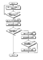
- FIG. 4 is a flowchart showing a flow of antenna switching processing according to the first embodiment of the present disclosure. The processing illustrated in FIG. 4 is executed by the control unit 112 when the receiving device 10 is powered on, for example.
- control unit 112 connects to the arbitrarily selected first antenna 101 and stands by (step S101).
- control unit 112 determines whether or not the synchronization signal detection unit 109 has detected the synchronization signal of the initial cell search (step S102).
- the control unit 112 returns to the procedure of the above step S101 when the synchronization signal detection unit 109 does not detect the synchronization signal of the initial cell search (step S102, No).
- the control unit 112 starts predetermined communication with the first antenna 101. (Step S103).
- the control unit 112 acquires the signal quality value V f from the signal quality measurement unit 110 (step S104).
- the signal quality value V f is a signal quality value of the reception signal acquired using the first antenna 101.
- control unit 112 determines whether or not the signal quality value V f is equal to or higher than a predetermined threshold value (step S105).
- step S105 when the signal quality value V f is equal to or higher than the predetermined threshold value (Yes in step S105), the control unit 112 does not execute the antenna switching and ends the process illustrated in FIG.
- control unit 112 the result of the determination, when if the signal quality value V f satisfies less than the predetermined threshold (step S105, No), that is, the signal quality value V f is smaller than a predetermined threshold, switching the selector 103 A signal is output and switched to the second antenna 102 (step S106).
- control unit 112 again acquires the signal quality value V s from the signal quality measurement section 110 (step S107).
- the signal quality value V s is the signal quality value of the received signal acquired using the second antenna 102.
- control unit 112 determines whether the signal quality value V s is less than the signal quality value V f (step S108).
- step S108 When the determination result shows that the signal quality value V s is smaller than the signal quality value V f (step S108, Yes), the control unit 112 outputs a switching signal to the selector 103 and switches to the first antenna 101 again. Is performed (step S109), and the processing shown in FIG. 4 ends.
- the control unit 112 determines that the signal quality value V s is not smaller than the signal quality value V f (step S108, No), that is, when the signal quality value V s is the signal quality value V f or more. , The antenna switching is not executed, and the processing shown in FIG. 4 ends.
- FIG. 5 is a diagram showing an example of a measurement result of throughput corresponding to each modulation scheme according to the second embodiment of the present disclosure.
- FIG. 5 shows the synchronization characteristics when the tester is wirelessly transmitted and the output level is changed, and the measurement result of the downlink signal throughput corresponding to each modulation method (QPSK or 16QAM).
- QPSK modulation method
- 16QAM 16QAM
- the throughput of each modulation method generally decreases.
- the output level is approximately "-66 (dbm)"
- synchronization is lost.
- the difference in output level from when the throughput becomes 50% or less to when synchronization is lost is about "5 (dbm)" in QPSK and "11 (dbm)” in 16QAM. That is, according to the measurement result shown in FIG. 5, the throughput may be 0% even if the synchronization is achieved.
- the procedure of setting the reference antenna is further executed. That is, the signal quality value is measured after synchronization is achieved, and the antenna switching is executed at the timing when the quality of the received signal cannot be maintained.
- the antenna whose received signal quality is maintained can be set as the antenna initially connected to the next initial cell search, increasing the possibility of responding to gradual changes in the environment of the transmission path. You can
- FIG. 6 is a flowchart showing a flow of antenna switching processing according to the second embodiment of the present disclosure.
- the antenna switching process according to the second embodiment is basically the same as the antenna switching process (FIG. 3) according to the first embodiment, but the first point is that it includes a procedure for setting a reference antenna. This is different from the antenna switching process according to the embodiment.
- the reference antenna corresponds to either the first antenna 101 or the second antenna 102.
- the sub antenna corresponds to an antenna that is not the reference antenna, that is, one of the first antenna 101 and the second antenna 102.
- the control unit 112 connects to the reference antenna and waits (step S201).
- the storage unit 111 can store status information indicating which antenna is the reference antenna from the first antenna 101 and the second antenna 102, for example.
- the control unit 112 can specify the reference antenna from the first antenna 101 and the second antenna 102 based on the status information stored in the storage unit 111.
- control unit 112 determines whether or not the synchronization signal detection unit 109 has detected the synchronization signal of the initial cell search (step S202).
- step S202 if the sync signal detection unit 109 does not detect the sync signal for the initial cell search (No in step S202), the control unit 112 returns to the procedure of step S201. On the contrary, when the synchronization signal detection unit 109 detects the synchronization signal of the initial cell search as a result of the determination (Yes in step S202), the control unit 112 starts predetermined communication with the reference antenna (step S202). 203).
- control unit 112 acquires the signal quality value V REF from the signal quality measuring unit 110 (step S204).
- the signal quality value V REF is the signal quality value of the received signal acquired using the reference antenna.
- control unit 112 determines whether or not the signal quality value V REF is equal to or higher than a predetermined threshold value (step S205).
- control unit 112 the result of the determination, if the signal quality value V REF is less than the predetermined threshold (step S205, No), i.e. if the signal quality value V REF is less than the predetermined threshold, switching the selector 103 A signal is output to switch to the sub antenna (step S206).
- the control unit 112 acquires the signal quality value V SUB from the signal quality measuring unit 110 (step S207).
- the signal quality value V SUB is a signal quality value of the received signal acquired using the sub antenna.
- control unit 112 determines whether or not the signal quality value V SUB is smaller than the signal quality value V REF (step S208).
- Step S208 when the signal quality value V SUB is smaller than the signal quality value V REF (Yes at Step S208), the control unit 112 outputs a switching signal to the selector 103 and switches to the reference antenna again. (Step S209), the process shown in FIG. 6 ends.
- step S208, No if the signal quality value V SUB is not smaller than the signal quality value V REF (step S208, No), the control unit 112 sets the sub-antenna to the reference antenna (step 210), and as shown in FIG. The processing shown is ended.
- FIG. 7 is a diagram showing a configuration example of the receiving device 10 according to the third embodiment of the present disclosure.
- the receiving apparatus 10 according to the third exemplary embodiment is different from the above-described exemplary embodiments in that it has a timer 113.
- the timer 113 is connected to the reference antenna or the sub-antenna and measures the time while waiting. The timer 113 outputs the measurement result to the control unit 112.
- the storage unit 111 stores a threshold value for determining whether or not the time measured by the timer 113 is within a preset predetermined time.
- the control unit 112 connects to the reference antenna and waits for the synchronization signal detection unit 109 to detect the synchronization signal at the time of initial cell search. Then, the control unit 112 resets the timer 113, switches to the sub-antenna, and waits for the detection of the synchronization signal when the synchronization signal is not detected within a fixed time. The control unit 112 alternately switches between the reference antenna and the sub antenna until the synchronization signal is detected.
- the procedure of the antenna switching process according to the third embodiment will be described with reference to the drawings.
- the control unit 112 connects to the reference antenna and waits (step S301).
- the storage unit 111 can store status information indicating which antenna is the reference antenna from the first antenna 101 and the second antenna 102, for example.
- the control unit 112 can specify the reference antenna from the first antenna 101 and the second antenna 102 based on the status information stored in the storage unit 111.
- control unit 112 determines whether or not the synchronization signal detection unit 109 has detected the synchronization signal of the initial cell search within a predetermined time (step S302).
- step S302, No if the synchronization signal of the initial cell search is not detected within the predetermined time (step S302, No), the control unit 112 switches to the sub antenna, connects to the sub antenna, and stands by (step S303). ..
- control unit 112 again determines whether or not the synchronization signal detection unit 109 has detected the synchronization signal for the initial cell search within the predetermined time (step S304).
- step S304, No if the synchronization signal of the initial cell search is not detected within the predetermined time (step S304, No), the control unit 112 switches to the reference antenna and returns to the procedure of step S301 described above.
- step S302 the control unit 112, as a result of the determination, when the synchronization signal of the initial cell search is detected within a predetermined time (step S302, Yes), the processing procedure following step S305 and step S305 shown in FIG. Move on to.
- the processing procedure shown in steps S305 to S312 shown in FIG. 9 is the same as that of steps S203 to S210 shown in FIG.
- step S304 if the result of determination is that a synchronization signal for initial cell search is detected within a predetermined time (step S304, Yes), the process proceeds to step S312 shown in FIG.
- the receiving device 10 has described the example in which the switching of the antenna is executed based on the signal quality value of the received signal, but this example is not particularly limited, and depending on the throughput, Switching of the antennas may be performed.
- the control unit 112 may switch to the second antenna 102 when the throughput of communication using the first antenna 101 is less than a predetermined threshold value.
- the receiving device 10 can be mounted on, for example, a smart meter used as the IoT device 3.
- FIG. 10 is a diagram showing a configuration example of a smart meter according to another embodiment.
- the smart meter 50 includes a first antenna 501, a second antenna 502, a selector 503, a wireless communication unit 504, a communication control unit 505, a storage unit 506, and a control unit 507.
- the measurement processing unit 508 is provided.
- the first antenna 501 and the second antenna 502 are devices that receive radio waves compatible with the LTE communication method. It corresponds to the first antenna 101 or the second antenna 102 according to the above-described embodiment.
- the first antenna 501 and the second antenna 502 obtain a reception signal by converting the electric wave received from the base station 2 into an electric signal.
- the selector 503 corresponds to the selector 103 according to the above-described embodiment, and switches to either the first antenna 501 or the second antenna 502 according to the control signal of the control unit 507.
- the wireless communication unit 504 is a communication processing unit compatible with the LTE communication method, and the wireless communication unit 504 includes a reception processing unit 541 and a transmission processing unit 542.
- the reception processing unit 541 performs down-conversion, removal of unnecessary frequency components, control of amplification level, quadrature demodulation, conversion into digital signals, removal of guard intervals, and fast Fourier transform for downlink signals which are reception signals.
- the frequency domain signal is extracted.
- the various processing functions provided by the reception processing unit 541 are processing functions for realizing the processing executed by the reception processing unit 100, the synchronization signal detection unit 109, and the signal quality measurement unit 110 included in the above-described receiving device 10. Including each.
- a reception circuit that processes a reception signal for a plurality of antennas (the first antenna 501 and the second antenna 502) is configured by one system.
- the transmission processing unit 542 performs transmission processing of uplink data. Processing such as inverse fast Fourier transform to time domain, addition of guard interval, generation of baseband digital signal, conversion to analog signal, quadrature modulation, up conversion, removal of extra frequency component, power amplification, etc. To do.
- a modulation signal is generated by modulating the data string that constitutes the transmission data using a predetermined modulation method, and after the generated modulation signal is oscillated and amplified at a predetermined frequency, filtering that removes unnecessary frequency components is performed. Each processing function for performing can be provided.
- the transmission processing unit 542 executes the transmission process under the control of the control unit 507.
- the communication control unit 505 is a communication interface that controls communication performed with other devices such as the management device 60 via the base station 2.
- the communication control unit 505 is a LAN interface such as NIC (Network Interface Card).
- the communication control unit 505 may be a wired interface or a wireless interface.
- the communication control unit 505 functions as a network communication unit of the smart meter 50.
- the communication control unit 505 communicates with other devices such as the management device 60 under the control of the control unit 507.
- the storage unit 506 stores programs and data used for control by the control unit 507.
- the storage unit 506 is realized by, for example, a RAM, a semiconductor memory element such as a flash memory, or a storage device such as a hard disk or an optical disk.
- the storage unit 506 can store, for example, a predetermined threshold value that the control unit 507 compares with the signal quality value calculated by the reception processing unit 541.
- the control unit 507 controls each unit of the smart meter 50.
- the control by the control unit 507 is realized, for example, by the CPU, the MPU, or the like executing a program stored in the smart meter 50 (for example, the program recorded in the storage unit 506) using the RAM or the like as a work area. It
- the control by the control unit 507 may be realized by an integrated circuit such as an ASIC or FPGA, for example.
- the control unit 507 can execute the process of switching between the first antenna 501 and the second antenna 502 based on the signal quality value of the received signal, similarly to the reception device 10 according to the above-described embodiment.
- the control unit 507 can execute a process of uploading data regarding the amount of electric power used, which is acquired from the later-described weighing processing unit 508, to the management device 60.
- the upload of data regarding the amount of power used may be executed at a control timing preset in the control unit 507, or may be executed in response to a request from the management device 60.
- the measurement processing unit 508 is a processing unit that automatically measures the amount of electricity used at a predetermined measurement timing, and the measurement processing unit 508 includes a measurement value storage unit 581.
- the measurement processing unit 508 can measure the data of the amount of electricity used every 30 minutes, or the amount of electricity used every 45 minutes, for example.
- the reception processing unit 541 having a simplified circuit configuration is provided.
- the smart meter 50 shown in FIG. 10 includes the control unit 507 that switches the antenna based on the signal quality value of the received signal. Therefore, it is possible to provide a product that can respond to a change in the communication environment while suppressing power consumption in a smart meter that is expected to perform regular communication for a long period.
- each component of each device shown in the drawings is functionally conceptual, and does not necessarily have to be physically configured as shown. That is, the specific form of distribution/integration of each device is not limited to that shown in the figure, and all or part of the device may be functionally or physically distributed/arranged in arbitrary units according to various loads and usage conditions. It can be integrated and configured.
- the synchronization signal detection unit 109, the signal quality measurement unit 110, and the control unit 112 illustrated in FIG. 2 may be functionally or physically integrated.
- the control unit 112 instead of the receiving device 10 including processing circuits corresponding to the synchronization signal detecting unit 109 and the signal quality measuring unit 110, the control unit 112 causes the synchronization signal detecting unit 109 to perform various processes and signal quality.
- Various processes executed by the measurement unit 110 may be realized.
- the base station 2 includes not only a structure having a function as the base station 2 (Structure) but also a device installed in the structure.
- the structure is, for example, a building such as a high-rise building, a house, a steel tower, a station facility, an airport facility, a port facility, and a stadium.
- the concept of a structure includes not only buildings but also non-building structures such as tunnels, bridges, dams, fences, steel columns, and equipment such as cranes, gates, and windmills.
- the concept of a structure includes not only structures on the ground (on land) or in the ground but also structures on the water such as a jetty and a megafloat, and structures underwater such as an ocean observation facility.
- the base station 2 may be a base station device configured to be movable.
- the base station may be a device installed in a moving body or the moving body itself.
- the mobile body may be a mobile terminal such as a smartphone.
- the moving body may be a moving body (for example, a vehicle such as an automobile, a bus, a truck, a train, or a linear motor car) that moves on the ground (on land), or moves in the ground (for example, in a tunnel). It may be a moving body (for example, subway).
- the moving body may be a moving body that moves on water (for example, a ship such as a passenger ship, a cargo ship, or a hovercraft), or a moving body that moves underwater (for example, a submersible boat, a submarine, an unmanned submarine, etc.). Submersible).
- the moving body may be a moving body that moves in the atmosphere (for example, an aircraft such as an airplane, an airship, or a drone), or a moving body that moves outside the atmosphere (for example, a satellite, a spaceship, a space station). , An artificial celestial body such as a probe).
- the receiving device according to the present disclosure processes a received signal acquired by one of the plurality of antennas corresponding to the LTE communication scheme and the plurality of antennas.
- One reception processing unit for Accordingly, the receiving device according to the present disclosure can reduce power consumption by simplifying the configuration for processing a received signal. Further, the receiving device according to the present disclosure can handle changes in the communication environment by using the plurality of antennas.
- the receiving device further includes a signal quality measuring unit and a control unit.
- the signal quality measuring unit calculates a signal quality value indicating the quality of the received signal acquired by the antenna used in the initial cell search, triggered by the detection of the synchronization signal in the initial cell search.
- the control unit switches the antenna when the signal quality value is less than the predetermined threshold value.
- the signal quality measuring unit uses at least one of an RSSI value, an RSQI value, a SINR value, a value associated with the RSSI value, a value associated with the RSQI value, and a value associated with the SINR value.
- the signal quality value is calculated based on the calculated result.
- the plurality of antennas includes a first antenna and a second antenna.
- the signal quality measuring unit recalculates the signal quality value after switching to the second antenna. If the signal quality value recalculated by the signal quality measuring unit after switching to the second antenna is smaller than the signal quality value calculated by the signal quality measuring unit before switching to the second antenna, the control unit determines Switch to 1 antenna.
- the receiving device can perform communication using an antenna with a reception signal having the highest quality.
- the plurality of antennas includes a first antenna and a second antenna.
- the signal quality measuring unit recalculates the signal quality value after switching to the second antenna. If the signal quality value recalculated by the signal quality measuring unit after switching to the second antenna is equal to or higher than the signal quality value calculated by the signal quality measuring unit before switching to the second antenna, the control unit determines Set 2 antennas as reference antennas. Then, the control unit connects to the second antenna and waits before performing the initial cell search.
- the receiving device can increase the possibility of being able to cope with a gradual change in the environment of the transmission path.
- control unit switches antennas when the synchronization signal at the time of initial cell search is not detected for a certain period of time. Accordingly, the receiving device according to the present disclosure can handle a situation in which synchronization with the base station is lost due to a sudden change in the environment of the transmission path.
- the first antenna and the second antenna acquire the received signal by the low speed communication method equivalent to the CAT-M1 method and the NB-IoT method.
- the receiving device can reduce power consumption as much as possible and realize long-term communication.
- the antenna control method according to the present disclosure is, for example, an antenna switching process performed by the receiving device 10 according to the embodiment.
- the computer calculates a signal quality value indicating the quality of the received signal acquired by the antenna used in the initial cell search, triggered by the detection of the synchronization signal in the initial cell search. .. Then, when the signal quality value is less than the predetermined threshold value, the computer switches the antenna.
- the antenna control method according to the present disclosure can prevent a decrease in communication quality due to a change in the environment of the transmission path while suppressing power consumption.
- the communication system according to the present disclosure is a communication system including a base station and a receiving device.
- a receiving device in such a communication system includes a plurality of antennas compatible with the LTE communication system and one reception processing unit that processes a reception signal acquired by any one of the plurality of antennas.
- the communication system according to the present disclosure can reduce power consumption in the receiving device by simplifying the configuration of the receiving device that processes a received signal.
- a receiving device including a plurality of antennas can handle changes in the environment of the transmission path.
- FIG. 11 is a hardware configuration diagram illustrating an example of a computer 1000 that realizes the functions of the reception device 10.
- the computer 1000 has a CPU 1100, a RAM 1200, a ROM (Read Only Memory) 1300, an HDD (Hard Disk Drive) 1400, a communication interface 1500, and an input/output interface 1600.
- the respective units of the computer 1000 are connected by a bus 1050.
- the CPU 1100 operates based on a program stored in the ROM 1300 or the HDD 1400, and controls each part. For example, the CPU 1100 expands a program stored in the ROM 1300 or the HDD 1400 into the RAM 1200 and executes processing corresponding to various programs.
- the ROM 1300 stores a boot program such as a BIOS (Basic Input Output System) executed by the CPU 1100 when the computer 1000 starts up, a program dependent on the hardware of the computer 1000, and the like.
- BIOS Basic Input Output System
- the HDD 1400 is a recording medium readable by the computer 1000 for non-temporarily recording a program executed by the CPU 1100 and data used by the program.
- the HDD 1400 is a recording medium for recording a program for realizing the antenna switching process shown in FIG. 3, for example.
- the communication interface 1500 is an interface for connecting the computer 1000 to an external network 1550 (for example, the Internet).
- the CPU 1100 receives data from another device or transmits the data generated by the CPU 1100 to another device via the communication interface 1500.
- the input/output interface 1600 is an interface for connecting the input/output device 1650 and the computer 1000.
- the CPU 1100 receives data from an input device such as a keyboard or a mouse via the input/output interface 1600.
- the CPU 1100 also transmits data to an output device such as a display, a speaker, a printer, etc. via the input/output interface 1600.
- the input/output interface 1600 may also function as a media interface for reading a program or the like recorded in a predetermined recording medium (medium).
- Examples of media include optical recording media such as DVD (Digital Versatile Disc) and PD (Phase change rewritable Disk), magneto-optical recording media such as MO (Magneto-Optical disk), tape media, magnetic recording media, and semiconductor memory. Is.
- optical recording media such as DVD (Digital Versatile Disc) and PD (Phase change rewritable Disk)
- magneto-optical recording media such as MO (Magneto-Optical disk), tape media, magnetic recording media, and semiconductor memory.
- the CPU 1100 of the computer 1000 executes a program loaded on the RAM 1200 (a program for realizing the antenna switching process, etc.).
- a program for realizing the antenna switching process etc.
- functions such as various processes executed by the control unit 112 of the receiving device 10 are realized.
- the HDD 1400 stores a program for implementing the antenna switching process according to the present disclosure, data stored in the storage unit 111, and the like.
- the CPU 1100 reads the program data 1450 from the HDD 1400 and executes the program data, but as another example, these programs may be acquired from another device via the external network 1550.
- a plurality of antennas compatible with the LTE communication system A reception processing unit that processes a reception signal acquired by any one of the plurality of antennas.
- a signal quality measurement unit that calculates a signal quality value indicating the quality of the received signal acquired by the antenna used during the initial cell search, triggered by the detection of the synchronization signal during the initial cell search,
- the receiving apparatus according to (1) further comprising: a control unit that executes switching of the antenna when the signal quality value is less than a predetermined threshold value.
- the signal quality measurement unit, RSSI value, RSQI value, and SINR value and The signal quality value is calculated based on a calculation result using at least one of a value associated with an RSSI value, a value associated with an RSQI value, and a value associated with an SINR value.
- the plurality of antennas includes a first antenna and a second antenna, The signal quality measurement unit, After switching to the second antenna, recalculate the signal quality value, The control unit is When the signal quality value recalculated by the signal quality measuring unit after switching to the second antenna is smaller than the signal quality value calculated by the signal quality measuring unit before switching to the second antenna. , The receiving device according to (2) or (3), which executes switching to the first antenna.
- the plurality of antennas includes a first antenna and a second antenna,
- the signal quality measurement circuit After switching to the second antenna, recalculate the signal quality value
- the control unit is When the signal quality value recalculated by the signal quality measuring unit after switching to the second antenna is equal to or higher than the signal quality value calculated by the signal quality measuring unit before switching to the second antenna.
- the control unit is The receiving device according to any one of (1) to (5), wherein the switching of the antennas is triggered by the fact that a synchronization signal at the time of initial cell search is not detected for a certain period.
- the first antenna and the second antenna are The receiving apparatus according to (4) above, which acquires a received signal by the LTE communication method using a low-speed communication method equivalent to the CAT-M1 method and the NB-IoT method.
- the receiving device In a communication system including a base station and a receiving device, The receiving device, A plurality of antennas compatible with the LTE communication system, A reception processing unit that processes a reception signal acquired by any one of the plurality of antennas.
Landscapes
- Engineering & Computer Science (AREA)
- Computer Networks & Wireless Communication (AREA)
- Signal Processing (AREA)
- Computer Security & Cryptography (AREA)
- Radio Transmission System (AREA)
- Mobile Radio Communication Systems (AREA)
- Circuits Of Receivers In General (AREA)
Abstract
受信装置(10)は、LTE通信方式に対応する複数のアンテナ(101、102)と、複数のアンテナ(101、102)のうちのいずれか一方で取得される受信信号を処理する1つの受信処理部(100)とを備える。
Description
本開示は、受信装置、アンテナ制御方法、及び通信システムに関する。
LTE(Long Time Evolution)を用いた無線通信システムを、スマートメータや環境モニタリング、自動車テレマティックスなどのIoT(Internet of Things)に応用する試みが進められている。たとえばCAT-M1方式やNB(Narrow Band)-IoT方式など、IoTに応用されるLTEの通信方式の標準化及び実用化が進められている。
ここで、通信品質の低下を防止するため、端末もしくは基地局においてアンテナの切替を行う技術が知られている。
LTE通信をIoTに応用する際、定期的で長期間の通信を期待される場合がある。このとき、受信装置の回路構成を簡素化することにより消費電力を抑えることができるが、その一方で、受信装置の回路の構成を簡素化すれば受信の多様性の効果が失われ、伝送路の環境の変化に対応できずに、通信品質の低下を招くおそれがある。
そこで、本開示では、消費電力を抑えつつ、通信環境の変化に対応できる受信装置、アンテナ制御方法、及び通信システムを提案する。
上記の課題を解決するために、本開示に係る一形態の受信装置は、LTE通信方式に対応する複数のアンテナと、前記複数のアンテナのうちのいずれか一方で取得される受信信号を処理する1つの受信処理部とを備える。
以下に、本開示の実施形態について図面に基づいて詳細に説明する。なお、以下の各実施形態において、同一の部位には同一の符号を付することにより重複する説明を省略する場合がある。
また、以下に示す項目順序に従って本開示を説明する。
1.第1の実施形態
1-1.第1の実施形態に係る通信システムの構成
1-2.第1の実施形態に係る受信装置の構成
1-3.第1の実施形態に係るアンテナ切替処理の手順
2.第2の実施形態
2-1.第2の実施形態に係るアンテナ切替処理の手順
3.第3の実施形態
3-1.第3の実施形態に係る受信装置の構成
3-2.第3の実施形態に係るアンテナ切替処理の手順
4.その他の実施形態
5.本開示に係る受信装置による効果
6.ハードウェア構成
1.第1の実施形態
1-1.第1の実施形態に係る通信システムの構成
1-2.第1の実施形態に係る受信装置の構成
1-3.第1の実施形態に係るアンテナ切替処理の手順
2.第2の実施形態
2-1.第2の実施形態に係るアンテナ切替処理の手順
3.第3の実施形態
3-1.第3の実施形態に係る受信装置の構成
3-2.第3の実施形態に係るアンテナ切替処理の手順
4.その他の実施形態
5.本開示に係る受信装置による効果
6.ハードウェア構成
(1.第1の実施形態)
[1-1.第1の実施形態に係る通信システムの構成]
図1は、本開示の第1の実施形態に係る通信システム1の一例を示す図である。図1に示す通信システム1は、LTE通信方式を利用した通信(以下、「LTE通信」と記載する)をIoTに利用するIoTシステムである。かかる通信システム1は、基地局2と、IoT機器3とを含む。
[1-1.第1の実施形態に係る通信システムの構成]
図1は、本開示の第1の実施形態に係る通信システム1の一例を示す図である。図1に示す通信システム1は、LTE通信方式を利用した通信(以下、「LTE通信」と記載する)をIoTに利用するIoTシステムである。かかる通信システム1は、基地局2と、IoT機器3とを含む。
基地局2は、LTE通信における無線信号の送受信を行う装置である。IoT機器3は、基地局2との間で無線信号を送受信することによりLTE通信を行う機器である。IoT機器3は、無線通信部4を備え、かかる無線通信部4は受信装置10を有する。
受信装置10は、基地局2から受信するLTE通信における無線信号を処理する装置である。受信装置10は、LTE通信に対応する第1アンテナ101及び第2アンテナ102を備える。
図12は、LTE通信方式の仕様の一例を示す図である。図12に示す「Cat-4」は、一般にスマートフォンなどに用いられる仕様である。図12に示す「Cat-M1」および「NB-IoT」は、一般にIoT機器に用いられる仕様である。
図12に示すように、IoT機器に用いられるLTE通信方式の仕様は、端末運用帯域幅(チャネル帯域幅)の狭帯域化、及び最大通信速度(伝送レート)を低速化することにより、消費電力の低減やモデム複雑性の緩和に特化した仕様となっている。一方、LTE通信方式を自動車テレマティックなどの移動体に適用する場合、IoT機器に用いられるLTE通信方式として図12に示す仕様では、通信が困難となることが予想される。同様に、基地局からの見通しが悪く、外部環境の変動およびマルチパスなどの影響が大きいスマートメータ又は環境モニタリングにLTE通信方式を適用する場合にも、図12に示す仕様では、通信が困難となることが予想される。
このような問題に対処する一般的な手法として、複数のアンテナで電波を受信するダイバシティがある。ダイバシティは、複数のアンテナで電波を受信し、質の良い受信信号を選択または合成することにより、受信レベルの低下を防止する手法である。図13は、比較例に係る受信装置30の構成例を示す図である。図13に示すように、比較例に係る受信装置30は、アンテナ31及びアンテナ32を用いたダイバシティの構成を採用している。かかる受信装置30は、基地局2からの電波を受信するアンテナ31及びアンテナ32を備える。また、かかる受信装置30は、アンテナ31で取得される受信信号を処理する回路(系統1)と、アンテナ32に取得される受信信号を処理する回路(系統2)とで構成された2系統の処理回路を備える。そして、かかる受信装置30は、アンテナ31及びアンテナ32で取得された受信信号から適切な受信信号を選択または合成できる。
上述したダイバシティによれば、受信レベルの低下を防止できるが、アンテナごとに受信信号を処理する処理回路がそれぞれ必要であることから、消費電力が問題となる。たとえばスマートメータなど、長期間で定期的な通信が期待されるIoT機器にLTE通信を利用する場合においては、受信装置の回路構成をできるだけ簡素化して、消費電力を抑える必要がある。
そこで、本開示の第1の実施形態では、消費電力を抑えつつ、伝送路の環境の変化に耐性を有する受信装置10を提案する。以下に、第1の実施形態に係る受信装置10の構成について具体的に説明する。
[1-2.第1の実施形態に係る受信装置の構成]
図2は、本開示の第1の実施形態に係る受信装置10の構成例を示す図である。受信装置10は、受信処理部100と、第1アンテナ101と、第2アンテナ102と、同期信号検出部109と、信号品質測定部110と、記憶部111と、制御部112とを備える。
図2は、本開示の第1の実施形態に係る受信装置10の構成例を示す図である。受信装置10は、受信処理部100と、第1アンテナ101と、第2アンテナ102と、同期信号検出部109と、信号品質測定部110と、記憶部111と、制御部112とを備える。
第1アンテナ101(第1アンテナの一例)、及び第2アンテナ102(第2アンテナの一例)は、LTE通信方式に対応した電波を受信する装置である。LTE通信方式として、CAT-M1方式、及びNB-IoT方式と同等の低速通信方式が例示される。第1アンテナ101及び第2アンテナ102は、基地局2から受信した電波を電気信号に変換することにより受信信号を取得する。第1アンテナ101及び第2アンテナ102は、取得した受信信号を受信装置10に入力する。受信装置10は、電源が投入されると、第1アンテナ101及び第2アンテナ102のいずれか一方に接続して待機する。
第1アンテナ101及び第2アンテナ102に接続される受信処理部100は、セレクタ103と、アンプ104と、ミキサ105と、ベースバンド処理部106と、変換部107と、復調部108とを有する。受信処理部100は、第1アンテナ101又は第2アンテナ102により取得される受信信号を処理する。受信処理部100は、第1アンテナ101及び第2アンテナ102に対して、セレクタ103、アンプ104、ミキサ105、ベースバンド処理部106、変換部107、及び復調部108をそれぞれ1つ備えた1系統の処理回路で構成される。
セレクタ103は、制御部112の制御信号に従って、第1アンテナ101及び第2アンテナ102のうちのいずれか一方に切り替える。
ベースバンド処理部106は、アンプ104およびミキサ105を介して取得した受信信号をベースバンド信号に変換する。ベースバンド処理部106は、アンプ104で増幅され、ミキサ105で周波数変換が行われた後の無線信号をベースバンド信号に変換してもよいが、ダイレクトコンバージョン方式により、無線信号を直接ベースバンド信号に変換してもよい。
変換部107は、アナログ信号であるベースバンド信号をディジタル信号のベースバンド信号に変換する。
復調部108は、基地局2から受信装置10へのダウンリンク信号の復調処理を実行する。すなわち、復調部108は、ダウンリング信号のチャネルの変調シンボルに対して、所定の変調方式を用いて、ディジタル信号に変換されたベースバンド信号の復調を行う。所定の変調方式として、QPSK(Quadrature Phase shift Keying)、又は16QAM(Quadrature Amplitude Modulation)等が例示される。
同期信号検出部109は、LTE通信が開始される前の初期段階でネットワーク内のセルを検出し、基地局2との同期を確立するために実行する初期セルサーチ時の同期信号を検出する。初期セルサーチは、主同期信号(PSS:Primary Synchronization Signal)を用いたプライマリ(初期)同期シーケンスと、副同期信号(SSS:secondary Synchronization Signal)を用いてセカンダリ同期シーケンスとで構成される。
信号品質測定部110は、後述する同期信号検出部109により同期信号が検出され、所定の通信が開始されると、受信信号の品質を測定する。具体的には、信号品質測定部110は、同期信号検出部109により初期セルサーチ時の同期信号が検出されることをトリガーとして、初期セルサーチ時に用いられたアンテナにより取得される受信信号の品質を示す信号品質値を算出する。信号品質測定部110は、算出した信号品質値を制御部112に出力する。
信号品質測定部110は、ベースバンド処理部106から取得するアナログ信号、若しくは変換部107から取得するディジタル信号に基づいて信号品質値を算出する。信号品質測定部110は、たとえばRSSI(Received Signal Strength Indicator)値を用いた演算結果に基づいて信号品質値を算出できる。また、信号品質測定部110は、RSRP(Reference Signal Received Power)値を用いた演算結果に基づいて信号品質値を算出できる。また、信号品質測定部110は、RSRQ(Reference Signal Received Quality)値を用いた演算結果に基づいて信号品質値を算出できる。また、信号品質測定部110は、SINR(Signal to Interference plus Noise Ratio)値を用いた演算結果に基づいて号品質値を算出できる。信号品質測定部110は、RSSI値、RSRP値、RSRQ値、及びSINR値のうちの少なくとも1つの値を用いた演算結果に基づいて、信号品質値を算出することもできる。また、信号品質測定部110は、RSSI値に関連する値、RSRP値に関連する値、RSRQ値に関連する値、及びSINR値に関連する値のうちの少なくとも1つの値を用いた演算結果に基づいて、信号品質値を算出できる。信号品質値の指標として例示するRSRP値、RSRQ値、SINR値、及びRSSI値はあくまで一例であり、その他の指標を用いてもよい。
また、信号品質測定部110は、制御部112から信号品質値の再測定を指示する制御信号を受け付けると、信号品質値を再度算出する。信号品質測定部110は、再度算出した信号品質値を制御部112に出力する。
記憶部111は、制御部112による制御に用いられるプログラムおよびデータを記憶する。記憶部111は、例えば、RAM、フラッシュメモリ(Flash Memory)等の半導体メモリ素子、または、ハードディスク、光ディスク等の記憶装置によって実現される。記憶部111は、たとえば制御部112が信号品質測定部110により算出された信号品質値と比較する所定の閾値を記憶できる。
図3は、本開示の第1の実施形態に係る出力レベルに応じたスループットごとの各信号品質値の測定結果の一例を示す図である。図3に示すように、送信側の出力レベルが「-52(dbm)」から「-58(dbm)」までの間は、スループットはほぼ横ばい状態となった。そして、送信側の出力レベルが「-60(dbm)」を下回ると、スループットも低下し始め、送信側の出力レベルが「-62(dbm)」に対応するスループットは、「-60(dbm)」の時の約3分の1の23.76%まで低下した。そして、、送信側の出力レベルが「-66(dbm)」に対応するスループットは0%となった。また、送信側の出力レベルの低下に従って、RSRP値、RSRQ値、SINR値、及びRSSI値の全ての信号品質値が総じて低下した。
図3に示す測定結果に基づき、IoT機器3で要求されるスループットに応じて、アンテナ切替のための所定の閾値を設定できる。たとえばIoT機器3で要求されるスループットが20%程度であれば、RSRP値に対応する所定の閾値を「-133」に設定できる。同様に、IoT機器3で要求されるスループットが20%程度であれば、RSRQ値に対応する閾値を「-30」に設定できる。同様に、IoT機器3で要求されるスループットが20%程度であれば、SINR値に対応する所定の閾値を「-11」に設定できる。同様に、IoT機器3で要求されるスループットが20%程度であれば、RSSI値に対応する所定の閾値を「-102」に設定できる。
制御部112は、受信装置10の各部を制御する。制御部112による制御は、例えば、CPUやMPU等によって、受信装置10内部に記憶されたプログラム(例えば、記憶部111に記録されたプログラム)がRAM等を作業領域として実行されることにより実現される。また、制御部112による制御は、例えば、ASICやFPGA等の集積回路により実現されてもよい。
制御部112は、たとえば受信装置10の電源が投入されると、第1アンテナ101及び第2アンテナ102のうちのいずれか一方を初期セルサーチの開始時のアンテナとして任意に選択し、選択したアンテナに接続して待機する。続いて、制御部112は、同期信号検出部109により初期セルサーチ時の同期信号が検出されると、所定の通信を開始し、信号品質測定部110から取得する信号品質値が所定の閾値未満であるか否かを判定する。制御部112は、信号品質測定部110から取得する信号品質値が所定の閾値未満である場合、アンテナの切替信号をセレクタ103に出力する。たとえば制御部112は、初期セルサーチの開始時に第1アンテナ101に接続している場合、第1アンテナ101から第2アンテナ102への切替を要求する切替信号をセレクタ103に出力する。
なお、制御部112は、信号品質値が所定の閾値以上である場合、アンテナの切替を実行しない。受信装置10は、現在接続中のアンテナを用いて通信を継続する。
アンテナの切替実行後、制御部112は、信号品質値の再測定を指示する制御信号を信号品質測定部110に出力する。そして、制御部112は、信号品質測定部110から取得したアンテナ切替後の信号品質値と、アンテナ切替前の信号品質値とを比較する。制御部112は、アンテナ切替後の信号品質値がアンテナ切替前の信号品質値よりも小さい場合、アンテナの切替信号をセレクタ103に再度出力し、アンテナの切替を実行する。制御部112は、第2アンテナ102への切替後に計測された信号品質値が、第2アンテナ102への切替前に計測された信号品質値よりも小さい場合、第2アンテナ102から第1アンテナ101への切替を再度実行する。すなわち制御部112は、第1アンテナ101から第2アンテナ102への切替後、受信信号の品質が低下した場合、第2アンテナ102よりも受信信号の品質が良かった第1アンテナ101に戻す。
なお、制御部112は、アンテナ切替後の信号品質値がアンテナ切替前の信号品質値以上である場合、アンテナの切替を実行しない。受信装置10は、現在接続中のアンテナを用いて通信を継続する。
図2に示す受信装置10が有する各部、すなわち受信処理部100、同期信号検出部109、信号品質測定部110、記憶部111、及び制御部112は、受信装置10の各機能を示す機能ブロックである。これら機能ブロックはソフトウェアブロックであってもよいし、ハードウェアブロックであってもよい。例えば、上述の機能ブロックが、それぞれ、ソフトウェア(マイクロプログラムを含む。)で実現される1つのソフトウェアモジュールであってもよいし、半導体チップ(ダイ)上の1つの回路ブロックであってもよい。勿論、各機能ブロックがそれぞれ1つのプロセッサ又は1つの集積回路であってもよい。機能ブロックの構成方法は任意である。なお、制御部112は上述の機能ブロックとは異なる機能単位で構成されていてもよい。たとえば同期信号検出部109及び信号品質測定部110により実現される機能が、それぞれ制御部112が実行するソフトウェアモジュールで実装されてもよい。あるいは同期信号検出部109及び信号品質測定部110により実現される機能が、1つの回路ブロック又は1つの集積回路で実装されてもよい。
[1-3.第1の実施形態に係るアンテナ切替処理の手順]
図4は、本開示の第1の実施形態に係るアンテナ切替処理の流れを示すフローチャートである。図4に示す処理は、たとえば受信装置10へ電源投入により、制御部112が実行する。
図4は、本開示の第1の実施形態に係るアンテナ切替処理の流れを示すフローチャートである。図4に示す処理は、たとえば受信装置10へ電源投入により、制御部112が実行する。
図4に示すように、制御部112は、任意に選択した第1アンテナ101に接続して待機する(ステップS101)。
続いて、制御部112は、同期信号検出部109により初期セルサーチの同期信号が検出されたか否かを判定する(ステップS102)。
制御部112は、判定の結果、同期信号検出部109により初期セルサーチの同期信号が検出されない場合(ステップS102,No)、上記ステップS101の手順に戻る。これとは反対に、制御部112は、判定の結果、同期信号検出部109により初期セルサーチの同期信号が検出されると(ステップS102,Yes)、第1アンテナ101で所定の通信を開始する(ステップS103)。
続いて、制御部112は、信号品質測定部110から信号品質値Vfを取得する(ステップS104)。信号品質値Vfは、第1アンテナ101を用いて取得された受信信号の信号品質値である。
続いて、制御部112は、信号品質値Vfが所定の閾値以上であるか否かを判定する(ステップS105)。
制御部112は、判定の結果、信号品質値Vfが所定の閾値以上である場合(ステップS105,Yes)、アンテナの切替は実行せず、図4に示す処理を終了する。
一方、制御部112は、判定の結果、信号品質値Vfが所定の閾値以上ではない場合(ステップS105,No)、すなわち信号品質値Vfが所定の閾値未満であるとき、セレクタ103に切替信号を出力して、第2アンテナ102へ切り替える(ステップS106)。
続いて、制御部112は、信号品質測定部110から信号品質値Vsを再度取得する(ステップS107)。信号品質値Vsは、第2アンテナ102を用いて取得された受信信号の信号品質値である。
続いて、制御部112は、信号品質値Vsが信号品質値Vfよりも小さいか否かを判定する(ステップS108)。
制御部112は、判定の結果、信号品質値Vsが信号品質値Vfよりも小さい場合(ステップS108,Yes)、セレクタ103に切替信号を出力して、再度、第1アンテナ101への切替を行い(ステップS109)、図4に示す処理を終了する。
一方、制御部112は、判定の結果、信号品質値Vsが信号品質値Vfよりも小さくない場合(ステップS108,No)、すなわち信号品質値Vsが信号品質値Vf以上であるとき、アンテナの切替は実行せず、図4に示す処理を終了する。
(2.第2の実施形態)
[2-1.第2の実施形態に係るアンテナ切替処理の手順]
第1の実施形態では、初期セルサーチを開始する際、第1アンテナ101及び第2アンテナ102のうちのいずれか一方を任意に選択し、初期セルサーチの開始時のアンテナに決定している。たとえば初期同期性能が通信全体のボトルネックとなっている場合には、アンテナ切替の効果が見込めない可能性がある。
[2-1.第2の実施形態に係るアンテナ切替処理の手順]
第1の実施形態では、初期セルサーチを開始する際、第1アンテナ101及び第2アンテナ102のうちのいずれか一方を任意に選択し、初期セルサーチの開始時のアンテナに決定している。たとえば初期同期性能が通信全体のボトルネックとなっている場合には、アンテナ切替の効果が見込めない可能性がある。
図5は、本開示の第2の実施形態に係る各変調方式に対応するスループットの測定結果の一例を示す図である。図5は、テスタを無線で送信し、出力レベルを変化させたときの同期特性と、各変調方式(QPSK又は16QAM)に対応するダウンリンク信号のスループットの測定結果を示すものである。なお、LTE通信方式として「Cat-M1」を採用する。
図5に示すように、出力レベルを低下させていくと、各変調方式のスループットは総じて低下する。各変調方式は、出力レベルがおよそ「-66(dbm)」で同期が取れなくなる。そして、スループットが50%以下になってから同期が取れなくなるまでの出力レベルの差は、QPSKでおよそ「5(dbm)」であり、16QAMでおよそ「11(dbm)」となっている。つまり、図5に示す測定結果によれば、同期が取れても、スループットが0%になる可能性がある。
そこで、以下に説明する第2の実施形態に係るアンテナ切替処理は、リファレンスアンテナ(基準アンテナの一例)を設定する手順をさらに実行する。すなわち、同期が取れた後に信号品質値の測定を行い、受信信号の品質が維持できなくなったタイミングでアンテナの切替を実行する。これにより、受信信号の品質が維持されたアンテナを、次回の初期セルサーチに初期接続するアンテナに設定しておくことができ、漸進的な伝送路の環境の変化に対応できる可能性を高めることができる。
図6は、本開示の第2の実施形態に係るアンテナ切替処理の流れを示すフローチャートである。第2の実施形態に係るアンテナ切替処理は、基本的には、第1の実施形態に係るアンテナ切替処理(図3)と同様であるが、リファレンスアンテナを設定する手順を含む点が第1の実施形態に係るアンテナ切替処理と相違する。以下の説明において、リファレンスアンテナは、第1アンテナ101及び第2アンテナ102のうちのいずれか一方に該当する。また、以下の説明において、サブアンテナは、リファレンスアンテナではないアンテナ、すなわち第1アンテナ101及び第2アンテナ102のうちのいずれか一方に該当する。
図6に示すように、制御部112は、リファレンスアンテナに接続して待機する(ステップS201)。記憶部111は、たとえば第1アンテナ101及び第2アンテナ102の中から、いずれのアンテナがリファレンスアンテナであるかのステータス情報を記憶できる。制御部112は、記憶部111に記憶されているステータス情報に基づいて、第1アンテナ101及び第2アンテナ102の中からリファレンスアンテナを特定できる。
続いて、制御部112は、同期信号検出部109により初期セルサーチの同期信号が検出されたか否かを判定する(ステップS202)。
制御部112は、判定の結果、同期信号検出部109により初期セルサーチの同期信号が検出されない場合(ステップS202,No)、上記ステップS201の手順に戻る。これとは反対に、制御部112は、判定の結果、同期信号検出部109により初期セルサーチの同期信号が検出されると(ステップS202,Yes)、リファレンスアンテナで所定の通信を開始する(ステップ203)。
続いて、制御部112は、信号品質測定部110から信号品質値VREFを取得する(ステップS204)。信号品質値VREFは、リファレンスアンテナを用いて取得された受信信号の信号品質値である。
続いて、制御部112は、信号品質値VREFが所定の閾値以上であるか否かを判定する(ステップS205)。
制御部112は、判定の結果、信号品質値VREFが所定の閾値以上である場合(ステップS205,Yes)、アンテナの切替を実行せず、図6に示す処理を終了する。
一方、制御部112は、判定の結果、信号品質値VREFが所定の閾値以上ではない場合(ステップS205,No)、すなわち信号品質値VREFが所定の閾値未満であるとき、セレクタ103に切替信号を出力して、サブアンテナへ切り替える(ステップS206)。
続いて、制御部112は、信号品質測定部110から信号品質値VSUBを取得する(ステップS207)。信号品質値VSUBは、サブアンテナを用いて取得された受信信号の信号品質値である。
続いて、制御部112は、信号品質値VSUBが信号品質値VREFよりも小さいか否かを判定する(ステップS208)。
制御部112は、判定の結果、信号品質値VSUBが信号品質値VREFよりも小さい場合(ステップS208,Yes)、セレクタ103に切替信号を出力して、再度、リファレンスアンテナへの切替を行い(ステップS209)、図6に示す処理を終了する。
一方、制御部112は、判定の結果、信号品質値VSUBが信号品質値VREFよりも小さくない場合(ステップS208,No)、サブアンテナをリファレンスアンテナに設定し(ステップ210)、図6に示す処理を終了する。
(3.第3の実施形態)
[3-1.第3の実施形態に係る受信装置の構成]
上記の実施形態では、初期セルサーチ時の同期信号の検出に応じて、受動的にアンテナの切替を実行する例を説明したが、たとえば突発的な伝送路の環境の変化により、基地局2との同期が取れなくなる場合がある。そこで、以下に説明する第3の実施形態では、突発的な伝送路の環境の変化に対応するべく、能動的にアンテナの切替を実行する受信装置10を提案する。
[3-1.第3の実施形態に係る受信装置の構成]
上記の実施形態では、初期セルサーチ時の同期信号の検出に応じて、受動的にアンテナの切替を実行する例を説明したが、たとえば突発的な伝送路の環境の変化により、基地局2との同期が取れなくなる場合がある。そこで、以下に説明する第3の実施形態では、突発的な伝送路の環境の変化に対応するべく、能動的にアンテナの切替を実行する受信装置10を提案する。
図7は、本開示の第3の実施形態に係る受信装置10の構成例を示す図である。第3の実施形態に係る受信装置10は、タイマ113を有する点が上記の実施形態とは相違する。
タイマ113は、リファレンスアンテナ又はサブアンテナに接続し、待機している間の時間を計測する。タイマ113は、計測結果を制御部112に出力する。
記憶部111は、タイマ113により計測された時間が、予め設定される所定時間内であるか否かを判定するための閾値を記憶する。
制御部112は、リファレンスアンテナに接続して、同期信号検出部109により初期セルサーチ時の同期信号が検出されるのを待機する。そして、制御部112は、一定時間内に同期信号が検出されない場合、タイマ113をリセットし、サブアンテナに切り替えて、同期信号の検出を待機する。制御部112は、同期信号が検出されるまで、リファレンスアンテナとサブアンテナとを交互に切り替える。以下、図を参照しつつ、第3の実施形態に係るアンテナ切替処理の手順を説明する。
[3-2.第3の実施形態に係るアンテナ切替処理の手順]
図8及び図9は、本開示の第3の実施形態に係るアンテナ切替処理の流れを示すフローチャートである。図9に示す処理手順は、図6に示すステップS203~S210と同様である。
図8及び図9は、本開示の第3の実施形態に係るアンテナ切替処理の流れを示すフローチャートである。図9に示す処理手順は、図6に示すステップS203~S210と同様である。
図8に示すように、制御部112は、リファレンスアンテナに接続して待機する(ステップS301)。記憶部111は、たとえば第1アンテナ101及び第2アンテナ102の中から、いずれのアンテナがリファレンスアンテナであるかのステータス情報を記憶できる。制御部112は、記憶部111に記憶されているステータス情報に基づいて、第1アンテナ101及び第2アンテナ102の中からリファレンスアンテナを特定できる。
続いて、制御部112は、同期信号検出部109により所定時間内に初期セルサーチの同期信号が検出されたか否かを判定する(ステップS302)。
制御部112は、判定の結果、所定時間内に初期セルサーチの同期信号が検出されない場合(ステップS302,No)、サブアンテナへの切替を行い、サブアンテナに接続して待機する(ステップS303)。
そして、制御部112は、再び、同期信号検出部109により所定時間内に初期セルサーチの同期信号が検出されたか否かを判定する(ステップS304)。
制御部112は、判定の結果、所定時間内に初期セルサーチの同期信号が検出されない場合(ステップS304,No)、リファレンスアンテナへの切替を行い、上述したステップS301の手順に戻る。
上述のステップS302において、制御部112は、判定の結果、所定時間内に初期セルサーチの同期信号が検出された場合(ステップS302,Yes)、図9に示すステップS305及びステップS305に続く処理手順に移る。図9に示すステップS305~ステップS312に示す処理手順は、図6に示すステップS203~S210と同様であるので、説明は割愛する。
また、上述のステップS304において、判定の結果、所定時間内に初期セルサーチの同期信号が検出された場合(ステップS304,Yes)、図9に示すステップS312の処理手順に移る。
(4.その他の実施形態)
上述した実施形態では、受信装置10が、受信信号の信号品質値に基づいて、アンテナの切替を実行する例を説明したが、この例には特に限定される必要はなく、スループットに応じて、アンテナの切替を実行してもよい。たとえば制御部112は、第1アンテナ101を用いた通信のスループットが所定の閾値未満である場合、第2アンテナ102に切り替えるようにしてもよい。
上述した実施形態では、受信装置10が、受信信号の信号品質値に基づいて、アンテナの切替を実行する例を説明したが、この例には特に限定される必要はなく、スループットに応じて、アンテナの切替を実行してもよい。たとえば制御部112は、第1アンテナ101を用いた通信のスループットが所定の閾値未満である場合、第2アンテナ102に切り替えるようにしてもよい。
上述した実施形態に係る受信装置10は、たとえばIoT機器3として利用されるスマートメータに搭載できる。図10は、その他の実施形態に係るスマートメータの構成例を示す図である。
図10に示すように、スマートメータ50は、第1アンテナ501と、第2アンテナ502と、セレクタ503と、無線通信部504と、通信制御部505と、記憶部506と、制御部507と、計量処理部508とを備える。
第1アンテナ501及び第2アンテナ502は、LTE通信方式に対応した電波を受ける装置である。上述した実施形態に係る第1アンテナ101又は第2アンテナ102に対応する。第1アンテナ501及び第2アンテナ502は、基地局2から受信した電波を電気信号に変換することにより受信信号を取得する。
セレクタ503は、上述した実施形態に係るセレクタ103に対応し、制御部507の制御信号に従って、第1アンテナ501及び第2アンテナ502のうちのいずれか一方に切り替える。
無線通信部504は、LTE通信方式に対応する通信処理部であり、かかる無線通信部504は、受信処理部541及び送信処理部542を有する。
受信処理部541は、受信信号であるダウンリンク信号に対して、ダウンコンバート、不要な周波数成分の除去、増幅レベルの制御、直交復調、ディジタル信号への変換、ガードインターバルの除去、高速フーリエ変換による周波数領域信号の抽出等を行う。受信処理部541により提供される各種処理機能は、上述した受信装置10が備える受信処理部100、同期信号検出部109、並びに信号品質測定部110により実行される処理を実現するための各処理機能をそれぞれ含む。受信処理部541は、受信装置10と同様に、複数のアンテナ(第1アンテナ501及び第2アンテナ502)に対して、受信信号を処理する受信回路が1系統で構成される。
送信処理部542は、アップリンクデータの送信処理を行う。逆高速フーリエ変換による時間領域への変換、ガードインターバルの付加、ベースバンドのディジタル信号の生成、アナログ信号への変換、直交変調、アップコンバート、余分な周波数成分の除去、電力の増幅等の処理を行う。送信データを構成するデータ列を所定の変調方式を用いて変調することにより変調信号を生成し、生成した変調信号を所定の周波数で発振して増幅した後、不要な周波数成分を除去するフィルタリングを行うための各処理機能を提供できる。送信処理部542は、制御部507の制御に従って送信処理を実行する。
通信制御部505は、基地局2を介して、管理装置60などの他の装置との間で実行される通信を制御する通信インターフェイスである。通信制御部505は、たとえばNIC(Network Interface Card)等のLANインターフェイスである。通信制御部505は、有線インターフェイスであってもよいし、無線インターフェイスであってもよい。通信制御部505は、スマートメータ50のネットワーク通信手段として機能する。通信制御部505は、制御部507の制御に従って、管理装置60などの他の装置と通信する。
記憶部506は、制御部507による制御に用いられるプログラムおよびデータを記憶する。記憶部506は、例えば、RAM、フラッシュメモリ(Flash Memory)等の半導体メモリ素子、または、ハードディスク、光ディスク等の記憶装置によって実現される。記憶部506は、たとえば制御部507が受信処理部541により算出された信号品質値と比較する所定の閾値を記憶できる。
制御部507は、スマートメータ50の各部を制御する。制御部507による制御は、例えば、CPUやMPU等によって、スマートメータ50内部に記憶されたプログラム(例えば、記憶部506に記録されたプログラム)がRAM等を作業領域として実行されることにより実現される。また、制御部507による制御は、例えば、ASICやFPGA等の集積回路により実現されてもよい。制御部507は、上述した実施形態に係る受信装置10と同様に、受信信号の信号品質値に基づいて、第1アンテナ501及び第2アンテナ502を切り替える処理を実行できる。制御部507は、後述する計量処理部508から取得する電力の使用量に関するデータを管理装置60にアップロードする処理を実行できる。電力の使用量に関するデータのアップロードは、制御部507に予め設定される制御タイミングにより実行されてもよいし、管理装置60からの要求に応じて実行されてもよい。
計量処理部508は、所定の計測タイミングで電気の使用量を自動計測する処理部であり、かかる計量処理部508は、計量値格納部581を有する。計量処理部508は、たとえば30分ごとの電気の使用量、あるいは45分ごとの電気の使用量のデータを計測できる。
図10に示すスマートメータ50によれば、簡素化された回路構成を備えた受信処理部541を備える。そして、図10に示すスマートメータ50によれば、受信信号の信号品質値に基づいてアンテナの切替が実行する制御部507を備える。このため、長期間で定期的な通信が期待されるスマートメータにおいて、消費電力を抑えつつ、通信環境の変化に対応できる製品を提供できる。
また、上記各実施形態において説明した各処理のうち、自動的に行われるものとして説明した処理の全部または一部を手動的に行うこともでき、あるいは、手動的に行われるものとして説明した処理の全部または一部を公知の方法で自動的に行うこともできる。この他、上記文書中や図面中で示した処理手順、具体的名称、各種のデータやパラメータを含む情報については、特記する場合を除いて任意に変更することができる。例えば、各図に示した各種情報は、図示した情報に限られない。
また、図示した各装置の各構成要素は機能概念的なものであり、必ずしも物理的に図示の如く構成されていることを要しない。すなわち、各装置の分散・統合の具体的形態は図示のものに限られず、その全部または一部を、各種の負荷や使用状況などに応じて、任意の単位で機能的または物理的に分散・統合して構成することができる。たとえば、図2に示す同期信号検出部109と、信号品質測定部110と、制御部112とが機能的または物理的に統合されていてもよい。また、受信装置10が同期信号検出部109及び信号品質測定部110のそれぞれに対応する処理回路等を備える代わりに、制御部112が、同期信号検出部109により実行される各種処理と、信号品質測定部110により実行される各種処理とを実現してもよい。
また、上述してきた各実施形態及び変形例は、処理内容を矛盾させない範囲で適宜組み合わせることが可能である
また、本明細書に記載された効果はあくまで例示であって限定されるものでは無く、また他の効果があってもよい。
また、上記各実施形態において、基地局2は、基地局2としての機能を備えた構造物(Structure)のみならず、構造物に設置される装置も含まれる。構造物は、例えば、高層ビル、家屋、鉄塔、駅施設、空港施設、港湾施設、スタジアム等の建物である。なお、構造物という概念には、建物のみならず、トンネル、橋梁、ダム、塀、鉄柱等の構築物(Non-building structure)や、クレーン、門、風車等の設備も含まれる。また、構造物という概念には、地上(陸上)又は地中の構造物のみならず、桟橋、メガフロート等の水上の構造物や、海洋観測設備等の水中の構造物も含まれる。
また、基地局2は、移動可能に構成された基地局装置であってもよい。例えば、基地局は、移動体に設置される装置であってもよいし、移動体そのものであってもよい。移動体は、スマートフォンなどのモバイル端末であってもよい。また、移動体は、地上(陸上)を移動する移動体(例えば、自動車、バス、トラック、列車、リニアモーターカー等の車両)であってもよいし、地中(例えば、トンネル内)を移動する移動体(例えば、地下鉄)であってもよい。また、移動体は、水上を移動する移動体(例えば、旅客船、貨物船、ホバークラフト等の船舶)であってもよいし、水中を移動する移動体(例えば、潜水艇、潜水艦、無人潜水機等の潜水船)であってもよい。また、移動体は、大気圏内を移動する移動体(例えば、飛行機、飛行船、ドローン等の航空機)であってもよいし、大気圏外を移動する移動体(例えば、人工衛星、宇宙船、宇宙ステーション、探査機等の人工天体)であってもよい。
(5.本開示に係る受信装置10による効果)
上述のように、本開示に係る受信装置(実施形態における受信装置10など)は、LTE通信方式に対応する複数のアンテナと、複数のアンテナのうちのいずれか一方で取得される受信信号を処理する1つの受信処理部とを備える。これにより、本開示に係る受信装置は、受信信号を処理するための構成を簡素化することにより、消費電力を抑えることができる。また、本開示に係る受信装置は、複数のアンテナにより、通信環境の変化に対応できる。
上述のように、本開示に係る受信装置(実施形態における受信装置10など)は、LTE通信方式に対応する複数のアンテナと、複数のアンテナのうちのいずれか一方で取得される受信信号を処理する1つの受信処理部とを備える。これにより、本開示に係る受信装置は、受信信号を処理するための構成を簡素化することにより、消費電力を抑えることができる。また、本開示に係る受信装置は、複数のアンテナにより、通信環境の変化に対応できる。
また、本開示に係る受信装置は、信号品質測定部と、制御部とをさらに備える。信号品質測定部は、初期セルサーチ時の同期信号が検出されることをトリガーとして、当該初期セルサーチ時に用いられたアンテナにより取得される受信信号の品質を示す信号品質値を算出する。制御部は、信号品質値が所定の閾値未満である場合、アンテナの切替を実行する。これにより、本開示に係る受信装置は、受信信号の品質を示す信号品質に基づいて、アンテナを切り替えることにより、通信環境の変化に伴う通信品質の低下を防止できる。
また、信号品質測定部は、RSSI値、RSQI値、及びSINR値、並びに、RSSI値に関連する値、RSQI値に関連する値、及びSINR値に関連する値のうちの少なくとも1つの値を用いた演算結果に基づいて、信号品質値を算出する。これにより、本開示に係る受信装置は、種々の指標に基づく信号品質値を利用できる。
また、複数のアンテナは、第1アンテナおよび第2アンテナを含む。信号品質測定部は、第2アンテナへの切替後、信号品質値を再度算出する。制御部は、第2アンテナへの切替後に信号品質測定部により再度算出された信号品質値が、第2アンテナへの切替前に信号品質測定部により算出された信号品質値よりも小さい場合、第1アンテナへの切替を実行する。これにより、本開示に係る受信装置は、できるだけ受信信号の品質が良いアンテナにより通信を実行できる。
また、複数のアンテナは、第1アンテナおよび第2アンテナを含む。信号品質測定部は、第2アンテナへの切替後、信号品質値を再度算出する。制御部は、第2アンテナへの切替後に信号品質測定部により再度算出された信号品質値が、第2アンテナへの切替前に信号品質測定部により算出された信号品質値以上である場合、第2アンテナをリファレンスアンテナに設定する。そして、制御部は、初期セルサーチの実施前に第2アンテナに接続して待機する。これにより、本開示に係る受信装置は、漸進的な伝送路の環境の変化に対応できる可能性を高めることができる。
また、制御部は、初期セルサーチ時の同期信号が一定期間検出されないことをトリガーとして、アンテナの切替を実行する。これにより、本開示に係る受信装置は、突発的な伝送路の環境の変化により、基地局との同期が取れなくなる事態に対処できる。
また、第1アンテナ及び第2アンテナは、CAT-M1方式、及びNB-IoT方式と同等の低速通信方式による受信信号を取得する。これにより、本開示に係る受信装置は、消費電力をできるだけ低減し、長期的な通信を実現できる。
また、本開示に係るアンテナ制御方法は、たとえば実施形態に係る受信装置10によるアンテナ切替処理である。かかるアンテナ制御方法は、コンピュータが、初期セルサーチ時の同期信号が検出されることをトリガーとして、当該初期セルサーチ時に用いられたアンテナにより取得される受信信号の品質を示す信号品質値を算出する。そして、信号品質値が所定の閾値未満である場合、コンピュータがアンテナの切替を実行する。これにより、本開示に係るアンテナ制御方法は、消費電力を抑えつつ、伝送路の環境の変化に伴う通信品質の低下を防止できる。
また、本開示に係る通信システム(たとえば実施形態における通信システム1)は、基地局と、受信装置とを備える通信システムである。かかる通信システムにおける受信装置は、LTE通信方式に対応する複数のアンテナと、前記複数のアンテナのうちのいずれか一方で取得される受信信号を処理する1つの受信処理部とを備える。これにより、本開示に係る通信システムは、受信信号を処理する受信装置の構成を簡素化することにより、受信装置における消費電力を抑えることができる。また、本開示に係る通信システムは、複数のアンテナを備える受信装置が、伝送路の環境の変化に対応できる。
(6.ハードウェア構成)
上述してきた各実施形態に係る受信装置10は、例えば図11に示すような構成のコンピュータ1000によって実現される。以下、第1の実施形態に係る受信装置10を例に挙げて説明する。図11は、受信装置10の機能を実現するコンピュータ1000の一例を示すハードウェア構成図である。コンピュータ1000は、CPU1100、RAM1200、ROM(Read Only Memory)1300、HDD(Hard Disk Drive)1400、通信インターフェイス1500、及び入出力インターフェイス1600を有する。コンピュータ1000の各部は、バス1050によって接続される。
上述してきた各実施形態に係る受信装置10は、例えば図11に示すような構成のコンピュータ1000によって実現される。以下、第1の実施形態に係る受信装置10を例に挙げて説明する。図11は、受信装置10の機能を実現するコンピュータ1000の一例を示すハードウェア構成図である。コンピュータ1000は、CPU1100、RAM1200、ROM(Read Only Memory)1300、HDD(Hard Disk Drive)1400、通信インターフェイス1500、及び入出力インターフェイス1600を有する。コンピュータ1000の各部は、バス1050によって接続される。
CPU1100は、ROM1300又はHDD1400に格納されたプログラムに基づいて動作し、各部の制御を行う。例えば、CPU1100は、ROM1300又はHDD1400に格納されたプログラムをRAM1200に展開し、各種プログラムに対応した処理を実行する。
ROM1300は、コンピュータ1000の起動時にCPU1100によって実行されるBIOS(Basic Input Output System)等のブートプログラムや、コンピュータ1000のハードウェアに依存するプログラム等を格納する。
HDD1400は、CPU1100によって実行されるプログラム、及び、かかるプログラムによって使用されるデータ等を非一時的に記録する、コンピュータ1000が読み取り可能な記録媒体である。具体的には、HDD1400は、たとえば図3に示すアンテナ切替処理を実現するためのプログラムを記録する記録媒体である。
通信インターフェイス1500は、コンピュータ1000が外部ネットワーク1550(例えばインターネット)と接続するためのインターフェイスである。例えば、CPU1100は、通信インターフェイス1500を介して、他の機器からデータを受信したり、CPU1100が生成したデータを他の機器へ送信したりする。
入出力インターフェイス1600は、入出力デバイス1650とコンピュータ1000とを接続するためのインターフェイスである。例えば、CPU1100は、入出力インターフェイス1600を介して、キーボードやマウス等の入力デバイスからデータを受信する。また、CPU1100は、入出力インターフェイス1600を介して、ディスプレイやスピーカーやプリンタ等の出力デバイスにデータを送信する。また、入出力インターフェイス1600は、所定の記録媒体(メディア)に記録されたプログラム等を読み取るメディアインターフェイスとして機能してもよい。メディアとは、例えばDVD(Digital Versatile Disc)、PD(Phase change rewritable Disk)等の光学記録媒体、MO(Magneto-Optical disk)等の光磁気記録媒体、テープ媒体、磁気記録媒体、または半導体メモリ等である。
例えば、コンピュータ1000が第1の実施形態に係る受信装置10として機能する場合、コンピュータ1000のCPU1100は、RAM1200上にロードされたプログラム(アンテナ切替処理を実現するためのプログラムなど)を実行する。これにより、受信装置10の制御部112により実行される各種処理等の機能が実現される。また、HDD1400には、本開示に係るアンテナ切替処理を実現するためのプログラムや、記憶部111に記憶されるデータなどが格納される。なお、CPU1100は、プログラムデータ1450をHDD1400から読み取って実行するが、他の例として、外部ネットワーク1550を介して、他の装置からこれらのプログラムを取得してもよい。
なお、本技術は以下のような構成も取ることができる。
(1)
LTE通信方式に対応する複数のアンテナと、
前記複数のアンテナのうちのいずれか一方で取得される受信信号を処理する1つの受信処理部と
を備える受信装置。
(2)
初期セルサーチ時の同期信号が検出されることをトリガーとして、当該初期セルサーチ時に用いられたアンテナにより取得される受信信号の品質を示す信号品質値を算出する信号品質測定部と、
前記信号品質値が所定の閾値未満である場合、前記アンテナの切替を実行する制御部と
をさらに備える
前記(1)に記載の受信装置。
(3)
前記信号品質測定部は、
RSSI値、RSQI値、及びSINR値、並びに、
RSSI値に関連する値、RSQI値に関連する値、及びSINR値に関連する値のうちの少なくとも1つの値を用いた演算結果に基づいて、前記信号品質値を算出する
前記(2)に記載の受信装置。
(4)
前記複数のアンテナは、第1アンテナおよび第2アンテナを含み、
前記信号品質測定部は、
前記第2アンテナへの切替後、前記信号品質値を再度算出し、
前記制御部は、
前記第2アンテナへの切替後に前記信号品質測定部により再度算出された前記信号品質値が、前記第2アンテナへの切替前に前記信号品質測定部により算出された前記信号品質値よりも小さい場合、前記第1アンテナへの切替を実行する
前記(2)又は(3)に記載の受信装置。
(5)
前記複数のアンテナは、第1アンテナおよび第2アンテナを含み、
前記信号品質測定回路は、
前記第2アンテナへの切替後、前記信号品質値を再度算出し、
前記制御部は、
前記第2アンテナへの切替後に前記信号品質測定部により再度算出された前記信号品質値が、前記第2アンテナへの切替前に前記信号品質測定部により算出された前記信号品質値以上である場合、前記第2アンテナをリファレンスアンテナに設定し、初期セルサーチの実施前に第2アンテナに接続して待機する
前記(2)又は(3)に記載の受信装置。
(6)
前記制御部は、
初期セルサーチ時の同期信号が一定期間検出されないことをトリガーとして、前記アンテナの切替を実行する
前記(1)~(5)のいずれかに記載の受信装置。
(7)
前記第1アンテナ及び前記第2アンテナは、
CAT-M1方式、及びNB-IoT方式と同等の低速通信方式を用いる前記LTE通信方式による受信信号を取得する
前記(4)に記載の受信装置。
(8)
コンピュータが、
初期セルサーチ時の同期信号が検出されることをトリガーとして、当該初期セルサーチ時に用いられたアンテナにより取得される受信信号の品質を示す信号品質値を算出し、
前記信号品質値が所定の閾値未満である場合、前記アンテナの切替を実行する
アンテナ制御方法。
(9)
基地局と、受信装置とを備える通信システムにおいて、
前記受信装置は、
LTE通信方式に対応する複数のアンテナと、
前記複数のアンテナのうちのいずれか一方で取得される受信信号を処理する1つの受信処理部と
を備える通信システム。
(1)
LTE通信方式に対応する複数のアンテナと、
前記複数のアンテナのうちのいずれか一方で取得される受信信号を処理する1つの受信処理部と
を備える受信装置。
(2)
初期セルサーチ時の同期信号が検出されることをトリガーとして、当該初期セルサーチ時に用いられたアンテナにより取得される受信信号の品質を示す信号品質値を算出する信号品質測定部と、
前記信号品質値が所定の閾値未満である場合、前記アンテナの切替を実行する制御部と
をさらに備える
前記(1)に記載の受信装置。
(3)
前記信号品質測定部は、
RSSI値、RSQI値、及びSINR値、並びに、
RSSI値に関連する値、RSQI値に関連する値、及びSINR値に関連する値のうちの少なくとも1つの値を用いた演算結果に基づいて、前記信号品質値を算出する
前記(2)に記載の受信装置。
(4)
前記複数のアンテナは、第1アンテナおよび第2アンテナを含み、
前記信号品質測定部は、
前記第2アンテナへの切替後、前記信号品質値を再度算出し、
前記制御部は、
前記第2アンテナへの切替後に前記信号品質測定部により再度算出された前記信号品質値が、前記第2アンテナへの切替前に前記信号品質測定部により算出された前記信号品質値よりも小さい場合、前記第1アンテナへの切替を実行する
前記(2)又は(3)に記載の受信装置。
(5)
前記複数のアンテナは、第1アンテナおよび第2アンテナを含み、
前記信号品質測定回路は、
前記第2アンテナへの切替後、前記信号品質値を再度算出し、
前記制御部は、
前記第2アンテナへの切替後に前記信号品質測定部により再度算出された前記信号品質値が、前記第2アンテナへの切替前に前記信号品質測定部により算出された前記信号品質値以上である場合、前記第2アンテナをリファレンスアンテナに設定し、初期セルサーチの実施前に第2アンテナに接続して待機する
前記(2)又は(3)に記載の受信装置。
(6)
前記制御部は、
初期セルサーチ時の同期信号が一定期間検出されないことをトリガーとして、前記アンテナの切替を実行する
前記(1)~(5)のいずれかに記載の受信装置。
(7)
前記第1アンテナ及び前記第2アンテナは、
CAT-M1方式、及びNB-IoT方式と同等の低速通信方式を用いる前記LTE通信方式による受信信号を取得する
前記(4)に記載の受信装置。
(8)
コンピュータが、
初期セルサーチ時の同期信号が検出されることをトリガーとして、当該初期セルサーチ時に用いられたアンテナにより取得される受信信号の品質を示す信号品質値を算出し、
前記信号品質値が所定の閾値未満である場合、前記アンテナの切替を実行する
アンテナ制御方法。
(9)
基地局と、受信装置とを備える通信システムにおいて、
前記受信装置は、
LTE通信方式に対応する複数のアンテナと、
前記複数のアンテナのうちのいずれか一方で取得される受信信号を処理する1つの受信処理部と
を備える通信システム。
1 通信システム
10 受信装置
101 第1アンテナ
102 第2アンテナ
103 セレクタ
104 アンプ
105 ミキサ
106 ベースバンド処理部
107 変換部
108 復調部
109 同期信号検出部
110 信号品質測定部
111 記憶部
112 制御部
113 タイマ
10 受信装置
101 第1アンテナ
102 第2アンテナ
103 セレクタ
104 アンプ
105 ミキサ
106 ベースバンド処理部
107 変換部
108 復調部
109 同期信号検出部
110 信号品質測定部
111 記憶部
112 制御部
113 タイマ
Claims (9)
- LTE通信方式に対応する複数のアンテナと、
前記複数のアンテナのうちのいずれか一方で取得される受信信号を処理する1つの受信処理部と
を備える受信装置。 - 初期セルサーチ時の同期信号が検出されることをトリガーとして、当該初期セルサーチ時に用いられたアンテナにより取得される受信信号の品質を示す信号品質値を算出する信号品質測定部と、
前記信号品質値が所定の閾値未満である場合、前記アンテナの切替を実行する制御部と
をさらに備える
請求項1に記載の受信装置。 - 前記信号品質測定部は、
RSSI値、RSQI値、及びSINR値、並びに、
RSSI値に関連する値、RSQI値に関連する値、及びSINR値に関連する値のうちの少なくとも1つの値を用いた演算結果に基づいて、前記信号品質値を算出する請求項2に記載の受信装置。 - 前記複数のアンテナは、第1アンテナおよび第2アンテナを含み、
前記信号品質測定部は、
前記第2アンテナへの切替後、前記信号品質値を再度算出し、
前記制御部は、
前記第2アンテナへの切替後に前記信号品質測定部により再度算出された前記信号品質値が、前記第2アンテナへの切替前に前記信号品質測定部により計測された前記信号品質値未満である場合、前記第1アンテナへの切替を実行する請求項2に記載の受信装置。 - 前記複数のアンテナは、第1アンテナおよび第2アンテナを含み、
前記信号品質測定部は、
前記第2アンテナへの切替後、前記信号品質値を再度算出し、
前記制御部は、
前記第2アンテナへの切替後に前記信号品質測定部により再度算出された前記信号品質値が、前記第2アンテナへの切替前に前記信号品質測定部により計測された前記信号品質値以上である場合、前記第2アンテナをリファレンスアンテナに設定し、初期セルサーチの実施前に第2アンテナに接続して待機する請求項2に記載の受信装置。 - 前記制御部は、
初期セルサーチ時の同期信号が一定期間検出されないことをトリガーとして、前記アンテナの切替を実行する
請求項2に記載の受信装置。 - 前記第1アンテナ及び前記第2アンテナは、
CAT-M1方式、及びNB-IoT方式と同等の低速通信方式による受信信号を取得する
請求項4に記載の受信装置。 - コンピュータが、
初期セルサーチ時の同期信号が検出されることをトリガーとして、当該初期セルサーチ時に用いられたアンテナにより取得される受信信号の品質を示す信号品質値を算出し、
前記信号品質値が所定の閾値未満である場合、前記アンテナの切替を実行する
アンテナ制御方法。 - 基地局と、受信装置とを備える通信システムにおいて、
前記受信装置は、
LTE通信方式に対応する複数のアンテナと、
前記複数のアンテナのうちのいずれか一方で取得される受信信号を処理する1つの受信処理部と
を備える通信システム。
Priority Applications (2)
| Application Number | Priority Date | Filing Date | Title |
|---|---|---|---|
| DE112019006702.8T DE112019006702T5 (de) | 2019-01-21 | 2019-12-27 | Empfangsvorrichtung, antennensteuerungsverfahren und kommunikationssystem |
| US17/422,320 US12015940B2 (en) | 2019-01-21 | 2019-12-27 | Reception apparatus, antenna control method, and communication system |
Applications Claiming Priority (2)
| Application Number | Priority Date | Filing Date | Title |
|---|---|---|---|
| JP2019-008079 | 2019-01-21 | ||
| JP2019008079A JP2020120198A (ja) | 2019-01-21 | 2019-01-21 | 受信装置、アンテナ制御方法、及び通信システム |
Publications (1)
| Publication Number | Publication Date |
|---|---|
| WO2020153105A1 true WO2020153105A1 (ja) | 2020-07-30 |
Family
ID=71735753
Family Applications (1)
| Application Number | Title | Priority Date | Filing Date |
|---|---|---|---|
| PCT/JP2019/051626 Ceased WO2020153105A1 (ja) | 2019-01-21 | 2019-12-27 | 受信装置、アンテナ制御方法、及び通信システム |
Country Status (4)
| Country | Link |
|---|---|
| US (1) | US12015940B2 (ja) |
| JP (1) | JP2020120198A (ja) |
| DE (1) | DE112019006702T5 (ja) |
| WO (1) | WO2020153105A1 (ja) |
Families Citing this family (1)
| Publication number | Priority date | Publication date | Assignee | Title |
|---|---|---|---|---|
| US20240333371A1 (en) * | 2023-03-28 | 2024-10-03 | Silicon Laboratories Inc. | System, method and apparatus for antenna selection in a wireless communication system |
Citations (5)
| Publication number | Priority date | Publication date | Assignee | Title |
|---|---|---|---|---|
| JPH0614011A (ja) * | 1992-06-25 | 1994-01-21 | Matsushita Electric Works Ltd | ダイバーシチ受信アンテナ切替方式 |
| JP2007088860A (ja) * | 2005-09-22 | 2007-04-05 | Olympus Corp | 受信装置 |
| WO2014030183A1 (ja) * | 2012-08-21 | 2014-02-27 | 三菱電機株式会社 | 無線送受信機、無線送受信機のアンテナ選択方法 |
| WO2015125391A1 (ja) * | 2014-02-21 | 2015-08-27 | シャープ株式会社 | 通信装置、アンテナ切替制御プログラムおよび記録媒体 |
| JP2019009624A (ja) * | 2017-06-23 | 2019-01-17 | 株式会社タムラ製作所 | ダイバシティ受信装置 |
Family Cites Families (8)
| Publication number | Priority date | Publication date | Assignee | Title |
|---|---|---|---|---|
| JP2005260502A (ja) | 2004-03-10 | 2005-09-22 | Nec Corp | 通信装置と通信制御方法 |
| WO2007026890A1 (ja) | 2005-09-02 | 2007-03-08 | Olympus Medical Systems Corp. | 可搬型簡易画像表示装置及び受信システム |
| JP4823614B2 (ja) | 2005-09-02 | 2011-11-24 | オリンパス株式会社 | 可搬型簡易画像表示装置及び受信システム |
| US9143189B2 (en) * | 2012-03-30 | 2015-09-22 | Broadcom Corporation | Mobile device searching using multiple antennas |
| US9295069B2 (en) * | 2014-06-05 | 2016-03-22 | Qualcomm Incorporated | Radio frequency radiation exposure mitigation using antenna switching |
| US9356672B2 (en) * | 2014-08-01 | 2016-05-31 | Google Technology Holdings LLC | Apparatus and methods for adaptive antenna diversity in a multi-antenna system |
| JP2016127487A (ja) | 2015-01-06 | 2016-07-11 | 住友電気工業株式会社 | 無線通信装置及びアンテナ共用方法 |
| US11038769B2 (en) * | 2017-11-16 | 2021-06-15 | Verizon Patent And Licensing Inc. | Method and system for virtual network emulation and self-organizing network control using deep generative models |
-
2019
- 2019-01-21 JP JP2019008079A patent/JP2020120198A/ja active Pending
- 2019-12-27 US US17/422,320 patent/US12015940B2/en active Active
- 2019-12-27 WO PCT/JP2019/051626 patent/WO2020153105A1/ja not_active Ceased
- 2019-12-27 DE DE112019006702.8T patent/DE112019006702T5/de active Pending
Patent Citations (5)
| Publication number | Priority date | Publication date | Assignee | Title |
|---|---|---|---|---|
| JPH0614011A (ja) * | 1992-06-25 | 1994-01-21 | Matsushita Electric Works Ltd | ダイバーシチ受信アンテナ切替方式 |
| JP2007088860A (ja) * | 2005-09-22 | 2007-04-05 | Olympus Corp | 受信装置 |
| WO2014030183A1 (ja) * | 2012-08-21 | 2014-02-27 | 三菱電機株式会社 | 無線送受信機、無線送受信機のアンテナ選択方法 |
| WO2015125391A1 (ja) * | 2014-02-21 | 2015-08-27 | シャープ株式会社 | 通信装置、アンテナ切替制御プログラムおよび記録媒体 |
| JP2019009624A (ja) * | 2017-06-23 | 2019-01-17 | 株式会社タムラ製作所 | ダイバシティ受信装置 |
Also Published As
| Publication number | Publication date |
|---|---|
| US12015940B2 (en) | 2024-06-18 |
| JP2020120198A (ja) | 2020-08-06 |
| US20220104042A1 (en) | 2022-03-31 |
| DE112019006702T5 (de) | 2021-10-07 |
Similar Documents
| Publication | Publication Date | Title |
|---|---|---|
| US10499399B2 (en) | Method and device for performing beamforming | |
| CN108353291B (zh) | 用于移动小区的动态定位方法 | |
| EP3480974B1 (en) | Method for rssi measurement, network device, and terminal device | |
| KR101709685B1 (ko) | 선박을 위한 이동통신 중계 서비스 시스템 및 방법 | |
| US20220217602A1 (en) | Cell reselection method and apparatus | |
| WO2021159535A1 (zh) | 小区重选方法及装置 | |
| US9124366B2 (en) | Communication apparatus, communication system, control method, and storage medium | |
| JP5776791B2 (ja) | 無線基地局、無線通信システム、送信電力制御方法及び無線端末 | |
| JP7542731B2 (ja) | ネットワーク切り替え方法、装置と機器 | |
| WO2018095305A1 (zh) | 一种波束训练方法及装置 | |
| JP2011055237A (ja) | 無線通信性能試験方法、無線通信試験用測定装置及び無線通信性能試験システム | |
| CN114651413A (zh) | 确定准共址配置的方法及装置 | |
| US20150172967A1 (en) | Base station and cell selection method | |
| EP3017623B1 (en) | Method and apparatus of switching communications from a first channel to a second channel of higher-frequency | |
| KR20220149640A (ko) | 측정 제한을 위한 방법 및 디바이스 | |
| WO2020153105A1 (ja) | 受信装置、アンテナ制御方法、及び通信システム | |
| US9521633B2 (en) | Apparatus and method for selecting an optimum base station whose transmission power is to be changed | |
| CN112689322A (zh) | 功率控制方法、装置及设备 | |
| US9967789B2 (en) | Wireless terminal, wireless communication system, handover method and recording medium | |
| KR20240045061A (ko) | 비지상 네트워크에서 셀 재선택 평가 프로세스의 트리거링 | |
| US20120142290A1 (en) | Apparatus and method for detecting effective radiated power | |
| KR20230110037A (ko) | 해상 전파 음영지역 추정 및 안테나를 선택하는 방법 및 장치 | |
| Tsubouchi | Extended dependable air: heterogeneous wireless network for surface, space and sea | |
| US10278148B2 (en) | Wireless communication method and wireless communication device | |
| JP5197073B2 (ja) | 無線通信装置 |
Legal Events
| Date | Code | Title | Description |
|---|---|---|---|
| 121 | Ep: the epo has been informed by wipo that ep was designated in this application |
Ref document number: 19911969 Country of ref document: EP Kind code of ref document: A1 |
|
| 122 | Ep: pct application non-entry in european phase |
Ref document number: 19911969 Country of ref document: EP Kind code of ref document: A1 |