WO2020149367A1 - 流入部ユニットおよび沈殿槽 - Google Patents
流入部ユニットおよび沈殿槽 Download PDFInfo
- Publication number
- WO2020149367A1 WO2020149367A1 PCT/JP2020/001312 JP2020001312W WO2020149367A1 WO 2020149367 A1 WO2020149367 A1 WO 2020149367A1 JP 2020001312 W JP2020001312 W JP 2020001312W WO 2020149367 A1 WO2020149367 A1 WO 2020149367A1
- Authority
- WO
- WIPO (PCT)
- Prior art keywords
- inflow
- treated
- inflow pipe
- water
- opening
- Prior art date
- Legal status (The legal status is an assumption and is not a legal conclusion. Google has not performed a legal analysis and makes no representation as to the accuracy of the status listed.)
- Ceased
Links
Images





Classifications
-
- B—PERFORMING OPERATIONS; TRANSPORTING
- B01—PHYSICAL OR CHEMICAL PROCESSES OR APPARATUS IN GENERAL
- B01D—SEPARATION
- B01D21/00—Separation of suspended solid particles from liquids by sedimentation
- B01D21/02—Settling tanks with single outlets for the separated liquid
-
- B—PERFORMING OPERATIONS; TRANSPORTING
- B01—PHYSICAL OR CHEMICAL PROCESSES OR APPARATUS IN GENERAL
- B01D—SEPARATION
- B01D21/00—Separation of suspended solid particles from liquids by sedimentation
- B01D21/02—Settling tanks with single outlets for the separated liquid
- B01D21/04—Settling tanks with single outlets for the separated liquid with moving scrapers
- B01D21/06—Settling tanks with single outlets for the separated liquid with moving scrapers with rotating scrapers
-
- B—PERFORMING OPERATIONS; TRANSPORTING
- B01—PHYSICAL OR CHEMICAL PROCESSES OR APPARATUS IN GENERAL
- B01D—SEPARATION
- B01D21/00—Separation of suspended solid particles from liquids by sedimentation
- B01D21/02—Settling tanks with single outlets for the separated liquid
- B01D21/08—Settling tanks with single outlets for the separated liquid provided with flocculating compartments
-
- B—PERFORMING OPERATIONS; TRANSPORTING
- B01—PHYSICAL OR CHEMICAL PROCESSES OR APPARATUS IN GENERAL
- B01D—SEPARATION
- B01D21/00—Separation of suspended solid particles from liquids by sedimentation
- B01D21/24—Feed or discharge mechanisms for settling tanks
Definitions
- Embodiments of the present invention relate to an inflow unit and a settling tank.
- ⁇ A settling tank is known that settles and separates suspended solids contained in industrial wastewater. In the settling tank, it is desired to suppress the deterioration of the settling separation performance.
- the problem to be solved by the present invention is to provide an inflow unit and a settling tank that can suppress deterioration of sedimentation separation performance.
- the inflow unit has an inflow pipe, a storage unit, a treated water supply unit, and a first partition member.
- the inflow pipe is arranged around a rotating shaft that rotates the scraping plate of the settling tank.
- the accommodating portion is arranged radially outside the inflow pipe and surrounds the first end of the inflow pipe in the first direction.
- the storage portion can store the water to be treated which flows into the inside of the inflow pipe from the first end portion.
- the untreated water supply unit forms an untreated water supply port to the storage unit.
- the first partition member is arranged between the outer periphery of the accommodation portion and the inflow pipe in the radial direction.
- the first partition member extends along the circumferential direction of the inflow pipe.
- the first partition member has a first opening at a position different from the supply port.
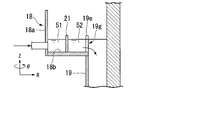
- FIG. 1 is a side sectional view showing the overall configuration of the settling tank of the first embodiment.
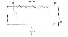
- FIG. 2 is a side view of the first end of the inflow pipe.
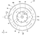
- FIG. 3 is a plan sectional view of the inflow unit according to the first embodiment.
- FIG. 4 is a side sectional view of the inflow unit according to the first embodiment.
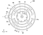
- FIG. 5 is a plan sectional view of the inflow unit according to the second embodiment.
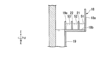
- FIG. 6 is a side sectional view of the inflow unit according to the second embodiment.
- FIG. 7 is a plan sectional view of the inflow unit according to the third embodiment.
- FIG. 8 is a side sectional view of the inflow unit according to the third embodiment.
- FIG. 9 is a plan sectional view of the inflow unit according to the fourth embodiment.
- FIG. 10 is a side sectional view of the inflow unit according to the fourth embodiment.
- the Z direction is the axial direction of the inflow pipe and the distributor.
- the Z direction is the vertical direction and the +Z direction (first direction) is the upward direction.
- the R direction is the radial direction of the inflow pipe and the distributor, and the +R direction is the outer direction.
- the ⁇ direction is the circumferential direction of the inflow pipe and the distributor, and the + ⁇ direction is the rotation direction of the rotary shaft.
- the R direction and the ⁇ direction are horizontal directions.
- the sedimentation tank 1 of the present embodiment is, for example, a sedimentation tank that separates minute SS (suspended material or suspended material) contained in water to be treated such as industrial wastewater from the water to be treated. It is a settling tank.
- minute SS suspended material or suspended material
- FIG. 1 is a side sectional view showing the overall configuration of the settling tank 1 of the present embodiment.
- the settling tank 1 has a tank body 11, an inflow unit 12, an overflow weir 13, a treated water discharge unit 14, a scraping unit 15, and a sludge drawing pipe 16.
- the flow of water to be treated is schematically shown by an arrow.
- the tank body 11 is a container having a bottomed tubular shape such as a cylindrical shape or a polygonal tubular shape.
- the tank body 11 includes, for example, a bottom wall 31 and a peripheral wall 32 that is erected upward from a peripheral portion of the bottom wall 31.
- the tank body 11 has an upper opening 33 at the upper end of the cylindrical peripheral wall 32.
- the tank body 11 stores water to be treated therein and precipitates flocs.
- the “floc” means a lump formed by a coagulation action or the like, and means, for example, a lint-like lump formed by adding a flocculant or the like to the water to be treated containing suspended solids.
- the tank body 11 is installed, for example, with the central axis 11c of the tank body 11 substantially aligned with the vertical direction. Further, a discharge port 31 a for discharging the precipitate to the outside of the tank 11 is provided at the center of the bottom wall 31 of the tank 11. The sludge drawing pipe 16 is connected to the discharge port 31a.
- a coagulation tank (not shown) for pretreating the water to be treated is arranged on the upstream side of the settling tank 1.
- a coagulant is added to the water to be treated.
- specific components in the water to be treated are aggregated to generate flocs. That is, the water to be treated flows into the settling tank 1 while containing the flocs.
- the inflow unit 12 has, for example, a treated water supply unit 17, a distribution unit (accommodation unit) 18, and an inflow pipe 19.
- the inflow unit 12 is arranged inside the tank 11 (that is, inside the settling tank 1).
- the inflow unit 12 causes the untreated water supplied from the coagulation tank through the untreated water supply unit 17 to flow into the tank body 11 through the distribution unit 18 and the inflow pipe 19.
- the term “arranged inside the tank body” as used in the present application means that at least a part of the inflow unit 12 is arranged on the upper opening 33 inside the tank body 11.
- the treated water supply unit 17 is, for example, a supply pipe or an inflow trough that extends from the outside of the tank body 11 to the inside of the tank body 11.
- trough means a structure that forms a groove.
- the untreated water supply unit 17 continuously supplies untreated water to the inside of the tank body 11.
- the untreated water supply unit 17 is connected to a distribution unit 18 described below to form a treated water supply port 17 a to the distribution unit 18.
- the supply port 17a is formed on the inner side surface of the outer peripheral wall 18a of the distribution unit 18 and faces the central axis 18c of the distribution unit 18.
- the water to be treated flows from the supply port 17a toward the central axis 18c of the distributor 18.
- the distribution unit 18 is also referred to as a “distributed trough” or an “inflow pool”.
- the distribution unit 18 is a trough having a predetermined volume formed by a cylindrical outer peripheral wall 18a and a ring-shaped bottom wall.
- the distribution unit 18 may have a shape different from the cylindrical shape, for example, a polygonal cylinder shape.
- the distributor 18 is arranged inside the tank 11.
- the central axis 18c of the distributor 18 is substantially coincident with the central axis 11c of the tank body 11.
- the size of the distribution unit 18 can be appropriately set according to the required treatment amount of the water to be treated and the size of the tank 11.
- the inflow pipe 19 is also called a “center well” or a “feed well”, and is formed in a tubular shape such as a cylindrical shape or a polygonal tubular shape.
- the inflow pipe 19 is arranged inside the distributor 18. That is, the distributor 18 is arranged radially outside the inflow pipe 19.
- the distributor 18 surrounds the first end 19e of the inflow pipe 19.
- the distributor 18 can store the water to be treated that flows into the inflow pipe 19 from the first end 19e.
- the central axis 19c of the inflow pipe 19 substantially coincides with the central axis 18c of the distributor 18 and the central axis 11c of the tank 11.
- the size of the inflow pipe 19 can be appropriately set according to the required treatment amount of the water to be treated and the size of the tank 11.
- FIG. 2 is a side view of the first end of the inflow pipe.
- a plurality of notches 19v which are also called “V notches", are formed in the first end portion 19e of the inflow pipe 19.
- the notch 19v is formed in a V-shape that tapers from the upper side toward the lower side.
- a plurality of notches 19v are continuously formed in the circumferential direction of the inflow pipe 19.
- the water to be treated that has flowed into the distribution unit 18 crosses over the weir 20 and flows into the inflow pipe 19 together with the flocs.
- the water level WL of the water to be treated in the distributor 18 is an intermediate position in the height direction of the notch 19v.
- the plurality of notches 19v evenly distribute the water to be treated flowing from the distributor 18 into the inflow pipe 19 in the circumferential direction of the inflow pipe 19.
- the lower end 19a of the inflow pipe 19 is separated from the bottom wall 31 of the tank body 11. That is, between the lower end 19a of the inflow pipe 19 and the bottom wall 31 of the tank body 11, a flow path is formed in which the water to be treated is dispersed in the horizontal direction. Further, the lower end 19a of the inflow pipe 19 has an opening (inflow port) 19b that allows the inside of the inflow pipe 19 to communicate with the inside of the tank 11.
- the treated water supplied from the treated water supply unit 17 into the inflow pipe 19 through the distribution unit 18 flows downward in the inflow pipe 19, and flows from the opening 19b of the lower end 19a of the inflow pipe 19 to the tank body. 11 is supplied.
- the water to be treated supplied from the inflow pipe 19 into the tank 11 slowly rises between the inner wall surface of the peripheral wall 32 of the tank 11 and the outer peripheral surface of the inflow pipe 19. For example, in this process, some of the flocs separate from the water to be treated and precipitate.
- the overflow weir 13 is provided above the tank body 11.
- the overflow weir 13 is provided in the tank 11 in a groove shape so as to accommodate the water to be treated overflowing from the upper end of the overflow weir 13.
- the overflow weir 13 is provided along the inner wall surface 32 a of the peripheral wall 32 of the tank body 11.
- the overflow weir 13 causes the treated water purified by separating and removing flocs to flow out to the treated water discharge section 14.
- the treated water discharge unit 14 is, for example, an outflow trough (or a discharge pipe or the like) that communicates with the inside of the overflow weir 13 and extends outside the tank body 11.
- the treated water discharger 14 causes the treated water overflowing from the upper end of the overflow weir 13 to flow out of the tank body 11.
- the water to be treated that has flowed out of the tank 11 is further processed, for example, and sent to a use point.
- the scratching unit 15 has a rotating shaft 41, a drive motor 42, a support member 43, and a plurality of scratching plates 44.
- the rotary shaft 41 is arranged at the center of the tank 11 (center of the inflow pipe 19).
- the rotary shaft 41 penetrates the inflow pipe 19 in the axial direction of the central axis 19c of the inflow pipe 19. That is, the inflow pipe 19 is arranged around the rotary shaft 41.
- the “axial direction of the central axis of the inflow pipe” is a direction substantially parallel to the central axis 19c of the inflow pipe 19.
- the drive motor 42 is connected to the rotary shaft 41 directly or via a transmission mechanism, and rotates the rotary shaft 41.
- the support member 43 is connected to the lower end of the rotary shaft 41 and extends in the radial direction.
- the plurality of scraping plates 44 are attached to the support member 43. That is, the rotating shaft 41 rotates the scraping plate 44 of the settling tank 1.
- the plurality of scraping plates 44 are provided from the supporting member 43 toward the bottom wall 31 of the tank body 11. According to the scraping unit 15 having such a structure, the rotation shaft 41 is rotated by the drive motor 42, and thus the support member 43 and the plurality of scraping plates 44 are rotated. As a result, the precipitate that has settled on the bottom wall 31 of the tank 11 is scraped toward the center of the bottom wall 31.
- the scraped sediment is discharged to the outside of the tank body 11 through the discharge port 31 a provided in the central portion of the bottom wall 31 and the sludge drawing pipe 16.
- FIG. 3 is a cross-sectional plan view taken along the line III-III in FIG.
- FIG. 4 is a side sectional view taken along the line IV-IV in FIG.
- the distributor 18 has a first partition plate 21.
- the first partition plate 21 is formed in a cylindrical shape having a first opening 21g in a part in the ⁇ direction.
- the first partition plate 21 is arranged coaxially with the central axis 18c of the distributor 18.
- the first partition plate 21 is arranged between the outer peripheral wall 18 a of the distributor 18 and the inflow pipe 19 in the R direction.
- the first partition plate 21 extends along the ⁇ direction.
- the first partition plate 21 stands up in the +Z direction from the inner bottom surface 18b of the distributor 18.
- the height from the inner bottom surface 18b of the distributor 18 to the end of the first partition plate 21 in the +Z direction is greater than or equal to the height from the inner bottom surface 18b of the distributor 18 to the first end 19e of the inflow pipe 19. That is, the end portion of the first partition plate 21 in the +Z direction is arranged above the water level of the water to be treated contained in the distributor 18.
- the first partition plate 21 partitions the distributor 18 into a first flow path 51 and a second flow path 52 in the R direction.
- the first flow path 51 is formed on the outer side in the R direction and between the outer peripheral wall 18 a of the distributor 18 and the first partition plate 21.
- the second flow path 52 is formed inside the R direction and between the first partition plate 21 and the inflow pipe 19.
- the first flow path 51 and the second flow path 52 are formed in an annular shape when viewed from the Z direction.
- the widths of the first flow path 51 and the second flow path 52 in the R direction are equal to each other.
- the first partition plate 21 has a first opening 21g.
- the first opening 21g is formed in a part of the first partition plate 21 in the ⁇ direction.
- the first opening 21g is formed from the inner bottom surface 18b of the distributor 18 to the end of the first partition plate 21 in the +Z direction.
- the first opening 21g is formed at a position different from the supply port 17a of the treated water supply unit 17 in the ⁇ direction.
- the first opening 21g is formed on the opposite side of the supply port 17a in the ⁇ direction.
- the first opening 21g is formed on the opposite side of the supply port 17a with the inflow pipe 19 interposed therebetween.
- the first opening 21g connects the first flow path 51 and the second flow path 52.
- the treated water is supplied to the distribution unit 18 from the supply port 17a of the treated water supply unit 17.
- the water to be treated comes into contact with the first partition plate 21 and flows into the first flow path 51, and does not directly flow into the inflow pipe 19.
- the water to be treated is divided into two directions of + ⁇ direction and ⁇ direction from the supply port 17a and flows through the first flow path 51.
- the water to be treated which has been divided into two and circulated, merges at the first merging portion 51c on the opposite side of the supply port 17a in the ⁇ direction.
- a first opening 21g of the first partition plate 21 is formed inside the first joining portion 51c in the R direction.
- the water to be treated flows into the second flow path 52 from the first opening 21g.
- the water to be treated is divided into two parts in the + ⁇ direction and ⁇ direction from the first opening 21g and flows through the second flow path 52.
- the water to be treated flows through the second flow path 52 along the outer peripheral surface of the inflow pipe 19. In the process of flowing through the second flow path 52, the water to be treated gets over the first end portion 19 e of the inflow pipe 19 and flows into the inflow pipe 19.
- flocs are generated in the coagulation tank on the upstream side of the settling tank 1.
- the water to be treated flows into the settling tank 1 while containing the flocs.
- the flocs may be broken and decomposed into fine flocs.
- the flocs are easily broken.
- the fine flocs are difficult to separate from the water to be treated and settle inside the sedimentation tank 1. Therefore, if the fine flocs flow into the inflow pipe 19, the settling separation performance of the settling tank 1 may deteriorate.
- the water to be treated that has flowed into the distribution unit 18 sequentially flows through the first flow channel 51 and the second flow channel 52.
- the frequency of association of fine flocs increases.
- the association of fine flocs becomes remarkable.
- the fine flocs are aggregated and the regeneration of the flocs is promoted.
- the regenerated flocs are separated from the water to be treated and settled inside the settling tank 1. Therefore, deterioration of the quality of the treated water is suppressed.
- Some heavy flocs cannot get over the first end 19e of the inflow pipe 19 and stay in the distributor 18.
- the accumulated flocs are deposited on the inner bottom surface 18b of the distribution unit 18.
- the flow of the water to be treated in the distribution unit 18 becomes nonuniform. Therefore, it becomes difficult to make the treated water uniformly flow into the inflow pipe 19 in the circumferential direction of the inflow pipe 19.
- the inflow of the water to be treated into the inflow pipe 19 becomes uneven, a high-speed local flow of the water to be treated is generated inside the settling tank 1. Thereby, the substantial residence time of the water to be treated inside the settling tank 1 is reduced. As a result, the sedimentation separation performance of the sedimentation tank 1 may decrease.
- the first partition plate 21 partitions the distributor 18 into the first flow path 51 and the second flow path 52 in the R direction. Thereby, the flow passage cross-sectional areas of the first flow passage 51 and the second flow passage 52 are reduced.
- the flow velocity of the water to be treated flowing through the first flow path 51 and the second flow path 52 is high enough to prevent the accumulation of flocs.
- the flocs flow into the inflow pipe 19 without accumulating in the distribution unit 18. Since the accumulation of flocs is suppressed, the flow of the water to be treated in the distribution unit 18 becomes uniform.
- the water to be treated flows into the inflow pipe 19 evenly in the circumferential direction of the inflow pipe 19. Inside the settling tank 1, the high-speed flow of the water to be treated does not occur locally, and the water to be treated flows uniformly at a low speed. Therefore, the deterioration of the sedimentation separation performance of the sedimentation tank 1 is suppressed.
- the inflow unit 12 has the inflow pipe 19, the distribution unit 18, the treated water supply unit 17, and the first partition plate 21.
- the inflow pipe 19 is arranged around a rotation shaft 41 that rotates the scraping plate 44 of the settling tank 1.
- the distribution part 18 is arrange
- the distributor 18 can store the water to be treated that flows into the inflow pipe 19 from the first end 19e.
- the treated water supply unit 17 forms a treated water supply port 17 a to the distribution unit 18.
- the first partition plate 21 is arranged between the outer circumference of the distributor 18 and the inflow pipe 19 in the ⁇ direction.
- the first partition plate 21 extends along the ⁇ direction.
- the first partition plate 21 has a first opening 21g at a position different from the supply port 17a.
- the first partition plate 21 forms a first flow path 51 and a second flow path 52 in the distributor 18.
- the first flow path 51 and the second flow path 52 are connected by the first opening 21g.
- the water to be treated sequentially flows through the first flow path 51 and the second flow path 52 and flows into the inflow pipe 19. Since the flow path of the water to be treated in the distribution unit 18 becomes long, regeneration of flocs from the fine flocs is promoted. Therefore, the deterioration of the sedimentation separation performance of the sedimentation tank 1 is suppressed.
- the flow passage cross-sectional area of the water to be treated in the distribution unit 18 becomes smaller. The flow velocity of the water to be treated is so high that flock accumulation does not occur. Since the accumulation of flocs is suppressed, the water to be treated flows evenly at a low speed inside the settling tank 1. Therefore, the deterioration of the sedimentation separation performance of the sedimentation tank 1 is suppressed.
- the first opening 21g is formed on the opposite side of the supply port 17a in the ⁇ direction. As a result, the flow path of the water to be treated in the distribution unit 18 becomes the longest. Therefore, the deterioration of the sedimentation separation performance of the sedimentation tank 1 is suppressed.
- the widths of the first flow path 51 and the second flow path 52 in the R direction are equal to each other.
- the width of the first flow path 51 may be narrower than the width of the second flow path 52.
- the flow velocity of the water to be treated in the first flow path 51 is increased.
- a part of the water to be treated that has flowed into the distributor 18 from the water to be treated supply 17 flows in the first flow path 51 in a turbulent state. This increases the chances of association of the fine flocs and promotes the regeneration of the flocs.
- FIG. 5 and 6 are explanatory views of the inflow unit according to the second embodiment.
- FIG. 5 is a plan sectional view of a portion corresponding to the line III-III in FIG.
- FIG. 6 is a side sectional view taken along line VI-VI in FIG.
- the inflow unit 212 of the second embodiment differs from that of the first embodiment in that it has a second partition plate 22.
- the description of the same parts as those of the first embodiment is omitted.
- the distributor 18 of the inflow unit 212 has a second partition plate (second partition member) 22 in addition to the first partition plate 21.
- the second partition plate 22 is formed in a cylindrical shape having a second opening 22g in a part in the ⁇ direction.
- the second partition plate 22 is arranged coaxially with the central axis 18c of the distributor 18.
- the second partition plate 22 is arranged between the first partition plate 21 and the inflow pipe 19 in the R direction.
- the second partition plate 22 extends along the ⁇ direction.
- the second partition plate 22 stands up in the +Z direction from the inner bottom surface 18b of the distributor 18.
- the height of the second partition plate 22 in the Z direction is the same as that of the first partition plate 21.
- the first partition plate 21 and the second partition plate 22 partition the distributor 18 into a first flow path 51, a second flow path 52, and a third flow path 53 in the R direction.
- the first flow path 51 is formed between the outer peripheral wall 18 a of the distributor 18 and the first partition plate 21.
- the second flow path 52 is formed between the first partition plate 21 and the second partition plate 22.
- the third flow path 53 is formed between the second partition plate 22 and the inflow pipe 19. The widths of the first flow path 51, the second flow path 52, and the third flow path 53 in the R direction are equal to each other.
- the second partition plate 22 has a second opening 22g.
- the second opening 22g is formed in a part of the second partition plate 22 in the ⁇ direction.
- the second opening 22g is formed at a position different from the first opening 21g in the ⁇ direction.
- the second opening 22g is formed on the opposite side of the first opening 21g in the ⁇ direction.
- the second opening 22g is formed on the opposite side of the first opening 21g with the inflow pipe 19 interposed therebetween.
- the second opening 22g connects the second flow path 52 and the third flow path 53.
- the water to be treated flows through the first flow path 51 and the second flow path 52 as in the first embodiment. That is, the water to be treated is divided into the + ⁇ direction and the ⁇ direction from the first opening 21g and flows through the second flow path 52.
- the water to be treated which has been divided into two and circulated, merges at the second merging portion 52c on the opposite side of the first opening 21g in the ⁇ direction.
- the fine flocs are remarkably associated with each other to promote regeneration of the flocs.
- a second opening 22g of the second partition plate 22 is formed inside the second joining portion 52c in the R direction.
- the water to be treated flows into the third flow path 53 from the second opening 22g.
- the water to be treated is divided into the + ⁇ direction and the ⁇ direction from the second opening 22g and flows through the third flow path 53.
- the water to be treated flows through the third flow path 53 along the outer peripheral surface of the inflow pipe 19. In the process of flowing through the third flow path 53, the water to be treated gets over the first end 19 e of the inflow pipe 19 and flows into the inflow pipe 19.
- the inflow unit 212 has the second partition plate 22.
- the second partition plate 22 is arranged inside the first partition plate 21 in the R direction.
- the second partition plate 22 has a second opening 22g on the side opposite to the first opening 21g in the ⁇ direction.
- the second partition plate 22 forms the third flow path 53 in the distributor 18.
- the second flow path 52 and the third flow path 53 are connected by the second opening 22g.
- the water to be treated sequentially flows through the first flow path 51, the second flow path 52, and the third flow path 53, and then flows into the inflow pipe 19. Since the flow path of the water to be treated in the distribution unit 18 is further lengthened, regeneration of flocs from fine flocs is promoted. Therefore, deterioration of the sedimentation separation performance of the sedimentation tank 1 is suppressed.
- the flow passage cross-sectional area of the water to be treated in the distribution unit 18 becomes smaller.
- the flow velocity of the water to be treated is so high that flock accumulation does not occur. Since the accumulation of flocs is suppressed, the water to be treated flows evenly at a low speed inside the settling tank 1. Therefore, deterioration of the sedimentation separation performance of the sedimentation tank 1 is suppressed.
- the widths of the first flow path 51, the second flow path 52, and the third flow path 53 in the R direction are equal to each other.
- the width of the first flow channel 51 may be narrower than the width of the second flow channel 52 and the third flow channel 53.
- the flow velocity of the first flow path 51 becomes faster.
- a part of the water to be treated that has flowed into the distributor 18 from the water to be treated supply 17 flows in the first flow path 51 in a turbulent state. This increases the chances of association of the fine flocs and promotes the regeneration of the flocs.
- the inflow unit 212 has two partition plates, a first partition plate 21 and a second partition plate 22.
- the inflow unit may have a plurality of partition plates of three or more. At this time, the openings of the partition plates adjacent to each other in the R direction are arranged on the opposite side in the ⁇ direction.
- FIG. 7 and 8 are explanatory views of the inflow unit according to the third embodiment.
- FIG. 7 is a plan sectional view of a portion corresponding to the line III-III in FIG.
- FIG. 8 is a side sectional view taken along the line VIIIVIII in FIG. 7.
- the inflow unit 312 of the third embodiment is different from that of the first embodiment in that it has an inflow opening 19g of an inflow pipe 19.
- description of the same parts as those of the first embodiment is omitted.
- the inflow pipe 19 has an inflow opening 19g.
- the inflow opening 19g is formed in a part of the inflow pipe 19 in the ⁇ direction.
- the inflow opening 19g is formed from the inner bottom surface 18b of the distributor 18 to the end of the inflow pipe 19 in the +Z direction.
- the inflow opening 19g is formed at a position different from the first opening 21g of the first partition plate 21 in the ⁇ direction.
- the inflow opening 19g is formed on the opposite side of the first opening 21g in the ⁇ direction.
- the inflow opening 19g is formed on the opposite side of the first opening 21g with the inflow pipe 19 interposed therebetween.
- the inflow opening 19g connects the second flow path 52 and the inside of the inflow pipe 19.
- the inflow pipe 19 does not have the plurality of notches 19v shown in FIG. 2 at the first end 19e in the +Z direction.
- the water to be treated does not flow over the first end portion 19e of the inflow pipe 19 and flow into the inflow pipe 19.
- the water to be treated flows into the inside of the inflow pipe 19 through the inflow opening 19g.
- the overflow weir 13 is arranged in the +Z direction more than in the first embodiment. As a result, the water level of the water to be treated inside the distribution unit 18 becomes equal to the water level of the water to be treated inside the inflow pipe 19.
- the water to be treated flows through the first flow path 51 and the second flow path 52 as in the first embodiment. That is, the water to be treated is divided into the two directions of + ⁇ direction and ⁇ direction from the first opening 21g of the first partition plate 21 and flows through the second flow path 52.
- the water to be treated which has been divided into two and circulated, merges at the second merging portion 52c on the opposite side of the first opening 21g in the ⁇ direction.
- An inflow opening 19g of the inflow pipe 19 is formed inside the second merging portion 52c in the R direction. The water to be treated flows into the inside of the inflow pipe 19 through the inflow opening 19g.
- the inflow pipe 19 of the inflow unit 312 has the inflow opening 19g.
- the inflow opening 19g is arranged on the opposite side of the first opening 21g in the ⁇ direction.
- the inflow opening 19g extends from the inner bottom surface 18b of the distribution portion 18 to the first end portion 19e in the +Z direction.
- FIG. 9 and 10 are explanatory views of the inflow unit according to the fourth embodiment.
- FIG. 9 is a plan sectional view of a portion corresponding to the line III-III in FIG.
- FIG. 10 is a side sectional view taken along line XX of FIG.
- the inflow unit 412 of the fourth embodiment is different from the second embodiment in that it has an inflow opening 19g of an inflow pipe 19.
- description of the same parts as those of the second embodiment is omitted.
- the inflow pipe 19 has an inflow opening 19g.
- the inflow opening 19g is formed in a part of the inflow pipe 19 in the ⁇ direction.
- the inflow opening 19g is formed from the inner bottom surface 18b of the distributor 18 to the end of the inflow pipe 19 in the +Z direction.
- the inflow opening 19g is formed at a position different from the second opening 22g of the second partition plate 22 in the ⁇ direction.
- the inflow opening 19g is formed on the opposite side of the second opening 22g in the ⁇ direction.
- the inflow opening 19g is formed on the opposite side of the second opening 22g with the inflow pipe 19 interposed therebetween.
- the inflow opening 19g connects the third flow path 53 and the inside of the inflow pipe 19.
- the inflow pipe 19 does not have the plurality of notches 19v shown in FIG. 2 at the first end 19e in the +Z direction.
- the water to be treated does not flow over the first end portion 19e of the inflow pipe 19 and flow into the inflow pipe 19.
- the water to be treated flows into the inside of the inflow pipe 19 through the inflow opening 19g.
- the overflow weir 13 is arranged in the +Z direction as compared with the second embodiment. As a result, the water level of the water to be treated inside the distribution unit 18 becomes equal to the water level of the water to be treated inside the inflow pipe 19.
- the water to be treated flows through the first flow path 51, the second flow path 52, and the third flow path 53, as in the second embodiment. That is, the water to be treated is divided into the two directions of + ⁇ direction and ⁇ direction from the second opening 22g of the second partition plate 22 and flows through the third flow path 53.
- the water to be treated which has been divided into two and circulated, merges at the third merging portion 53c on the opposite side of the second opening 22g in the ⁇ direction.
- the fine flocs are remarkably associated with each other to promote regeneration of the flocs.
- An inflow opening 19g of the inflow pipe 19 is formed inside the third merging portion 53c in the R direction. The water to be treated flows into the inside of the inflow pipe 19 through the inflow opening 19g.
- the inflow pipe 19 of the inflow unit 412 has the inflow opening 19g.
- the inflow opening 19g is arranged on the opposite side of the second opening 22g in the ⁇ direction.
- the inflow opening 19g extends from the inner bottom surface 18b of the distribution portion 18 to the first end portion 19e in the +Z direction.
- the inflow unit 12 has the first partition plate 21.
- the first partition plate 21 is arranged between the outer circumference of the distributor 18 and the inflow pipe 19 in the R direction.
- the first partition plate 21 extends along the ⁇ direction and has a first opening 21g at a position different from the supply port 17a. As a result, it is possible to suppress deterioration of the sedimentation separation performance of the sedimentation tank 1.
Landscapes
- Chemical & Material Sciences (AREA)
- Chemical Kinetics & Catalysis (AREA)
- Separation Of Suspended Particles By Flocculating Agents (AREA)
Abstract
実施形態の流入部ユニットは、流入管と、収容部と、被処理水供給部と、第1仕切部材と、を持つ。流入管は、沈殿槽の掻寄板を回転させる回転シャフトの周囲に配置される。収容部は、前記流入管の径方向の外側に配置され、前記流入管の第1方向の第1端部を取り囲む。収容部は、前記第1端部から前記流入管の内側に流入する被処理水を収容可能である。被処理水供給部は、前記収容部への被処理水の供給口を形成する。第1仕切部材は、前記径方向において前記収容部の外周と前記流入管との間に配置される。第1仕切部材は、前記流入管の周方向に沿って伸びる。第1仕切部材は、前記供給口とは異なる位置に第1開口を有する。
Description
本発明の実施形態は、流入部ユニットおよび沈殿槽に関する。
工業廃水などに含まれる浮遊物質等を沈降分離させる沈殿槽が知られている。沈殿槽には、沈降分離性能の低下を抑制することが望まれている。
本発明が解決しようとする課題は、沈降分離性能の低下を抑制することができる流入部ユニットおよび沈殿槽を提供することである。
実施形態の流入部ユニットは、流入管と、収容部と、被処理水供給部と、第1仕切部材と、を持つ。流入管は、沈殿槽の掻寄板を回転させる回転シャフトの周囲に配置される。収容部は、前記流入管の径方向の外側に配置され、前記流入管の第1方向の第1端部を取り囲む。収容部は、前記第1端部から前記流入管の内側に流入する被処理水を収容可能である。被処理水供給部は、前記収容部への被処理水の供給口を形成する。第1仕切部材は、前記径方向において前記収容部の外周と前記流入管との間に配置される。第1仕切部材は、前記流入管の周方向に沿って伸びる。第1仕切部材は、前記供給口とは異なる位置に第1開口を有する。
以下、実施形態の流入部ユニットおよび沈殿槽を、図面を参照して説明する。なお以下の説明では、同一または類似の機能を有する構成に同一の符号を付す。そして、それら構成の重複する説明は省略する場合がある。
本願において、極座標系のZ方向、R方向およびθ方向が以下のように定義される。Z方向は流入管および分配部の軸方向である。例えば、Z方向は鉛直方向であり、+Z方向(第1方向)は上方向である。R方向は流入管および分配部の径方向であり、+R方向は外側の方向である。θ方向は流入管および分配部の周方向であり、+θ方向は回転シャフトの回転方向である。例えば、R方向およびθ方向は水平方向である。
(第1の実施形態)
第1の実施形態について説明する。
本実施形態の沈殿槽1は、例えば、工業廃水などの被処理水に含まれる微小のSS(懸濁物質または浮遊物質)を被処理水から分離させる沈殿槽であり、例えば沈降分離法が用いられる沈殿槽である。
第1の実施形態について説明する。
本実施形態の沈殿槽1は、例えば、工業廃水などの被処理水に含まれる微小のSS(懸濁物質または浮遊物質)を被処理水から分離させる沈殿槽であり、例えば沈降分離法が用いられる沈殿槽である。
まず、沈殿槽1の全体構成について、図1を用いて説明する。
図1は、本実施形態の沈殿槽1の全体構成を示す側面断面図である。
図1に示されるように、沈殿槽1は、槽体11、流入部ユニット12、溢流堰13、被処理水排出部14、掻寄ユニット15、および汚泥引抜管16を有する。なお各図では、被処理水の流れを矢印で模式的に示す。
図1は、本実施形態の沈殿槽1の全体構成を示す側面断面図である。
図1に示されるように、沈殿槽1は、槽体11、流入部ユニット12、溢流堰13、被処理水排出部14、掻寄ユニット15、および汚泥引抜管16を有する。なお各図では、被処理水の流れを矢印で模式的に示す。
槽体11は、円筒状または多角筒状などの有底の筒状に形成された容器である。槽体11は、例えば、底壁31と、底壁31の周縁部から上方に向けて起立した周壁32と、を含む。槽体11は、筒状の周壁32の上端部に上部開口部33を有する。槽体11は、内部に被処理水を貯留するとともに、フロックを沈殿させる。なお「フロック」とは、凝集作用などによって生成された塊状物を意味し、例えば浮遊物質を含む被処理水中に凝集剤などが添加されることで生じる綿くず状の塊状物を意味する。槽体11は、例えば槽体11の中心軸11cを鉛直方向と略一致させて設置されている。また、槽体11の底壁31の中央部には、沈殿物を槽体11の外部に排出する排出口31aが設けられている。排出口31aには、汚泥引抜管16が接続されている。
沈殿槽1の上流側には、被処理水を前処理するための凝集槽(図示略)が配置されている。凝集槽において、凝集剤が被処理水に投入される。これにより、被処理水中の特定の成分が凝集して、フロックが生成される。すなわち、被処理水はフロックを含んだ状態で沈殿槽1内に流入する。
流入部ユニット12は、例えば被処理水供給部17と、分配部(収容部)18と、流入管19と、を有する。流入部ユニット12は、槽体11の内側(すなわち、沈殿槽1の内側)に配置される。流入部ユニット12は、凝集槽から被処理水供給部17を通じて供給された被処理水を、分配部18および流入管19を介して槽体11内に流入させる。なお本願で言う「槽体の内側に配置される」とは、槽体11の内側の上部開口部33上に流入部ユニット12の少なくとも一部が配置されることを意味する。
被処理水供給部17は、例えば槽体11の外側から槽体11の内側に延びた供給配管または流入トラフなどである。本願で言う「トラフ」とは、溝を形成する構造体を意味する。被処理水供給部17は、被処理水を連続的に槽体11の内側に供給する。被処理水供給部17は、後述の分配部18に接続されて、分配部18への被処理水の供給口17aを形成している。供給口17aは、分配部18の外周壁18aの内側面上に、分配部18の中心軸18cを向いて形成される。被処理水は、供給口17aから分配部18の中心軸18cに向かって流入する。
分配部18は、「分散トラフ」または「流入プール」とも称される。本実施形態において分配部18は、円筒形の外周壁18aおよびリング状の底壁によって形成された所定の容積を有するトラフである。なお、分配部18は、円筒形とは異なった形状、例えば多角筒形とすることも可能である。分配部18は、槽体11の内側に配置される。分配部18の中心軸18cは、槽体11の中心軸11cと略一致している。分配部18の大きさは、被処理水の必要処理量や槽体11の大きさに応じて、適宜設定可能である。
流入管19は、「センターウェル」または「フィードウェル」とも称され、例えば円筒状または多角筒状などの筒状に形成されている。流入管19は、分配部18の内側に配置される。すなわち分配部18は、流入管19の径方向の外側に配置される。分配部18は、流入管19の第1端部19eを取り囲む。分配部18は、第1端部19eから流入管19に流入する被処理水を収容可能である。図1に示されるように、流入管19の中心軸19cは、分配部18の中心軸18cおよび槽体11の中心軸11cと略一致している。流入管19の大きさは、被処理水の必要処理量や槽体11の大きさに応じて、適宜設定可能である。
流入管19の上方向(第1方向)の第1端部19eは、分配部18の底面よりも上方に突出して、分配部18内に堰20を形成している。堰20の高さは、少なくとも分配部18の外周壁18aよりも低く、且つ溢流堰13よりも高く形成される。
図2は、流入管の第1端部の側面図である。流入管19の第1端部19eには、「Vノッチ」とも称される複数の切欠き19vが形成される。切欠き19vは、上方向から下方向に向かって先細るV字状に形成される。複数の切欠き19vが、流入管19の周方向に連続して形成される。
図2は、流入管の第1端部の側面図である。流入管19の第1端部19eには、「Vノッチ」とも称される複数の切欠き19vが形成される。切欠き19vは、上方向から下方向に向かって先細るV字状に形成される。複数の切欠き19vが、流入管19の周方向に連続して形成される。
分配部18内に流入した被処理水は、フロックとともに堰20を乗り越えて流入管19の内側に流入する。分配部18における被処理水の水位WLは、切欠き19vの高さ方向の中間位置である。複数の切欠き19vは、分配部18から流入管19に流入する被処理水を、流入管19の周方向において均等に分配する。
流入管19の下端19aは、槽体11の底壁31から離れている。すなわち、流入管19の下端19aと槽体11の底壁31との間には、被処理水が水平方向に分散して流れる流路が形成されている。また、流入管19の下端19aは、流入管19の内部を槽体11内に連通させる開口部(流入口)19bを有する。被処理水供給部17から分配部18を介して流入管19内に供給された被処理水は、流入管19内を下方に向けて流れ、流入管19の下端19aの開口部19bから槽体11内に供給される。流入管19から槽体11内に供給された被処理水は、槽体11の周壁32の内壁面と流入管19の外周面との間をゆっくりと上昇する。例えばこの過程で、フロックの一部が被処理水から分離して沈殿する。
溢流堰13は、槽体11の上部に設けられている。溢流堰13は、この溢流堰13の上端から溢れた被処理水を収容できるように、槽体11内に溝状に設けられている。例えば、溢流堰13は、槽体11の周壁32の内壁面32aに沿って設けられている。溢流堰13は、フロックの分離除去が行われて清浄化された被処理水を被処理水排出部14に流出させる。
被処理水排出部14は、例えば溢流堰13の内部に連通するとともに槽体11の外側に伸びた流出トラフ(または排出配管など)である。被処理水排出部14は、溢流堰13の上端から溢れた被処理水を槽体11の外部に流出させる。槽体11の外部に流出した被処理水は、例えばさらに別の処理が行われて、ユースポイントに送出される。
掻寄ユニット15は、回転シャフト41と、駆動モータ42と、支持部材43と、複数の掻寄板44と、を有する。回転シャフト41は、槽体11の中心部(流入管19の中心部)に配置されている。回転シャフト41は、流入管19の中心軸19cの軸方向において、流入管19を貫通している。すなわち流入管19は、回転シャフト41の周囲に配置される。なお「流入管の中心軸の軸方向」とは、流入管19の中心軸19cと略平行な方向である。駆動モータ42は、直接または伝達機構などを介して回転シャフト41に接続され、回転シャフト41を回転させる。支持部材43は、回転シャフト41の下端に連結されて径方向に伸びている。複数の掻寄板44は、支持部材43に取り付けられている。すなわち、回転シャフト41は沈殿槽1の掻寄板44を回転させる。複数の掻寄板44は、支持部材43から槽体11の底壁31に向けて設けられている。このような構成の掻寄ユニット15によれば、駆動モータ42によって回転シャフト41が回転されることで、支持部材43および複数の掻寄板44が回転する。これにより、槽体11の底壁31に沈殿した沈殿物が底壁31の中央部に向けて掻寄せられる。掻寄せられた沈殿物は、底壁31の中央部に設けられた排出口31aおよび汚泥引抜管16を通じて槽体11の外部に排出される。
分配部18の仕切板(仕切部材、バッフル板)について説明する。
図3および図4は、第1の実施形態の流入部ユニットの説明図である。図3は、図1のIII-III線における平面断面図である。図4は、図3のIV-IV線における側面断面図である。図3に示されるように、分配部18は、第1仕切板21を有する。
図3および図4は、第1の実施形態の流入部ユニットの説明図である。図3は、図1のIII-III線における平面断面図である。図4は、図3のIV-IV線における側面断面図である。図3に示されるように、分配部18は、第1仕切板21を有する。
第1仕切板21は、θ方向の一部に第1開口21gを有する円筒状に形成される。第1仕切板21は、分配部18の中心軸18cと同軸状に配置される。第1仕切板21は、R方向において分配部18の外周壁18aと流入管19との間に配置される。第1仕切板21は、θ方向に沿って伸びる。図4に示されるように、第1仕切板21は、分配部18の内底面18bから+Z方向に起立する。分配部18の内底面18bから第1仕切板21の+Z方向の端部までの高さは、分配部18の内底面18bから流入管19の第1端部19eまでの高さ以上である。すなわち、第1仕切板21の+Z方向の端部は、分配部18に収容される被処理水の水位よりも上方に配置される。
図3に示されるように、第1仕切板21は、R方向において分配部18を第1流路51と第2流路52とに仕切る。第1流路51は、R方向の外側であって、分配部18の外周壁18aと第1仕切板21との間に形成される。第2流路52は、R方向の内側であって第1仕切板21と流入管19との間に形成される。第1流路51および第2流路52は、Z方向からみて円環状に形成される。第1流路51および第2流路52のR方向の幅は、相互に同等である。
第1仕切板21は、第1開口21gを有する。第1開口21gは、第1仕切板21のθ方向の一部に形成される。第1開口21gは、分配部18の内底面18bから第1仕切板21の+Z方向の端部まで形成される。第1開口21gは、θ方向において、被処理水供給部17の供給口17aとは異なる位置に形成される。第1開口21gは、θ方向において、供給口17aの反対側に形成される。第1開口21gは、流入管19を挟んで供給口17aの反対側に形成される。第1開口21gは、第1流路51と第2流路52とを接続する。
被処理水供給部17の供給口17aから分配部18に被処理水が供給される。被処理水は、第1仕切板21当接して第1流路51に流入し、直接的に流入管19に流入しない。被処理水は、供給口17aから+θ方向および-θ方向の二手に分かれて、第1流路51を流通する。二手に分かれて流通した被処理水は、θ方向における供給口17aの反対側の第1合流部51cで合流する。第1合流部51cのR方向の内側には、第1仕切板21の第1開口21gが形成されている。被処理水は、第1開口21gから第2流路52に流入する。被処理水は、第1開口21gから+θ方向および-θ方向の二手に分かれて、第2流路52を流通する。被処理水は、流入管19の外周面に沿って第2流路52を流通する。第2流路52を流通する過程で、被処理水は、流入管19の第1端部19eを乗り越えて流入管19の内側に流入する。
前述されたように、沈殿槽1の上流側の凝集槽でフロックが生成される。被処理水は、フロックを含んだ状態で沈殿槽1に流入する。被処理水が分配部18に供給されるとき、フロックが壊れて微細フロックに分解される場合がある。特に、被処理水供給部17から分配部18への流入落差が大きい場合や、分配部18への流入速度が大きい場合などに、フロックが壊れやすい。微細フロックは、沈殿槽1の内部で被処理水から分離して沈降しにくい。そのため、微細フロックが流入管19に流入すると、沈殿槽1の沈降分離性能が低下する可能性がある。
前述されたように、分配部18に流入した被処理水は、第1流路51および第2流路52を順に流れる。長い流路を流れることで、微細フロックの会合頻度が多くなる。特に、第1合流部51cで被処理水が合流するとき、微細フロックの会合が顕著になる。これにより、微細フロックが凝集して、フロックの再生成が促進される。再生成したフロックは、沈殿槽1の内部で被処理水から分離して沈降する。したがって、既処理水の水質低下が抑制される。
一部の重いフロックは、流入管19の第1端部19eを乗り越えることができずに、分配部18に滞留する。滞留するフロックは、分配部18の内底面18bに堆積する。フロックが不均一に堆積すると、分配部18における被処理水の流れが不均一になる。そのため、流入管19の周方向において被処理水を均等に流入管19に流入させることが困難になる。被処理水の流入管19への流入が不均一になると、沈殿槽1の内部において局所的な被処理水の高速流が発生する。これにより、沈殿槽1の内部における被処理水の実質的滞留時間が減少する。その結果、沈殿槽1の沈降分離性能が低下する可能性がある。
前述されたように、第1仕切板21は、R方向において分配部18を第1流路51と第2流路52とに仕切る。これにより、第1流路51および第2流路52の流路断面積が小さくなる。第1流路51および第2流路52を流れる被処理水の流速は、フロックの堆積が発生しない程度に早くなる。フロックは、分配部18に堆積することなく、流入管19に流入する。フロックの堆積が抑制されるので、分配部18における被処理水の流れが均一になる。被処理水は、流入管19の周方向において均等に流入管19に流入する。沈殿槽1の内部において、局所的に被処理水の高速流が発生することなく、被処理水が均等に低速で流通する。したがって、沈殿槽1の沈降分離性能の低下が抑制される。
以上のように、流入部ユニット12は、流入管19と、分配部18と、被処理水供給部17と、第1仕切板21と、を持つ。流入管19は、沈殿槽1の掻寄板44を回転させる回転シャフト41の周囲に配置される。分配部18は、流入管19の径方向の外側に配置され、流入管19の+Z方向の第1端部19eを取り囲む。分配部18は、第1端部19eから流入管19の内側に流入する被処理水を収容可能である。被処理水供給部17は、分配部18への被処理水の供給口17aを形成する。第1仕切板21は、θ方向において分配部18の外周と流入管19との間に配置される。第1仕切板21は、θ方向に沿って伸びる。第1仕切板21は、供給口17aとは異なる位置に第1開口21gを有する。
第1仕切板21により、分配部18に第1流路51および第2流路52が形成される。第1流路51および第2流路52は、第1開口21gにより接続される。被処理水は、第1流路51および第2流路52を順に流れて、流入管19に流入する。分配部18における被処理水の流路が長くなるので、微細フロックからフロックの再生成が促進される。したがって、沈殿槽1の沈降分離性能の低下が抑制される。また、分配部18における被処理水の流路の流路断面積が小さくなる。被処理水の流速は、フロックの堆積が発生しない程度に早くなる。フロックの堆積が抑制されるので、沈殿槽1の内部において被処理水が均等に低速で流通する。したがって、沈殿槽1の沈降分離性能の低下が抑制される。
第1開口21gは、θ方向において供給口17aの反対側に形成される。
これにより、分配部18における被処理水の流路が最も長くなる。したがって、沈殿槽1の沈降分離性能の低下が抑制される。
これにより、分配部18における被処理水の流路が最も長くなる。したがって、沈殿槽1の沈降分離性能の低下が抑制される。
流入部ユニット12では、第1流路51および第2流路52のR方向の幅が、相互に同等である。これに対して、第1流路51の幅は、第2流路52の幅より狭くてもよい。これにより、第1流路51における被処理水の流速が早くなる。被処理水供給部17から分配部18に流入した被処理水の一部は、乱流状態で第1流路51を流通する。これにより、微細フロックの会合機会が多くなり、フロックの再生成が促進される。
(第2の実施形態)
図5および図6は、第2の実施形態の流入部ユニットの説明図である。図5は、図1のIII-III線に相当する部分における平面断面図である。図6は、図5のVI-VI線における側面断面図である。第1の実施形態に対して、第2の実施形態の流入部ユニット212は、第2仕切板22を有する点で異なる。第2の実施形態のうち、第1の実施形態と同様の部分の説明は省略される。
図5および図6は、第2の実施形態の流入部ユニットの説明図である。図5は、図1のIII-III線に相当する部分における平面断面図である。図6は、図5のVI-VI線における側面断面図である。第1の実施形態に対して、第2の実施形態の流入部ユニット212は、第2仕切板22を有する点で異なる。第2の実施形態のうち、第1の実施形態と同様の部分の説明は省略される。
図5に示されるように、流入部ユニット212の分配部18は、第1仕切板21に加えて、第2仕切板(第2仕切部材)22を有する。
第2仕切板22は、θ方向の一部に第2開口22gを有する円筒状に形成される。第2仕切板22は、分配部18の中心軸18cと同軸状に配置される。第2仕切板22は、R方向において第1仕切板21と流入管19との間に配置される。第2仕切板22は、θ方向に沿って伸びる。図6に示されるように、第2仕切板22は、分配部18の内底面18bから+Z方向に起立する。第2仕切板22のZ方向の高さは、第1仕切板21と同等である。
第2仕切板22は、θ方向の一部に第2開口22gを有する円筒状に形成される。第2仕切板22は、分配部18の中心軸18cと同軸状に配置される。第2仕切板22は、R方向において第1仕切板21と流入管19との間に配置される。第2仕切板22は、θ方向に沿って伸びる。図6に示されるように、第2仕切板22は、分配部18の内底面18bから+Z方向に起立する。第2仕切板22のZ方向の高さは、第1仕切板21と同等である。
図5に示されるように、第1仕切板21および第2仕切板22は、R方向において分配部18を第1流路51と第2流路52と第3流路53とに仕切る。第1流路51は、分配部18の外周壁18aと第1仕切板21との間に形成される。第2流路52は、第1仕切板21と第2仕切板22との間に形成される。第3流路53は、第2仕切板22と流入管19との間に形成される。第1流路51、第2流路52および第3流路53のR方向の幅は、相互に同等である。
第2仕切板22は、第2開口22gを有する。第2開口22gは、第2仕切板22のθ方向の一部に形成される。第2開口22gは、θ方向において、第1開口21gとは異なる位置に形成される。第2開口22gは、θ方向において、第1開口21gの反対側に形成される。第2開口22gは、流入管19を挟んで第1開口21gの反対側に形成される。第2開口22gは、第2流路52と第3流路53とを接続する。
被処理水は、第1の実施形態と同様に第1流路51および第2流路52を流通する。すなわち、被処理水は、第1開口21gから+θ方向および-θ方向の二手に分かれて第2流路52を流通する。二手に分かれて流通した被処理水は、θ方向における第1開口21gの反対側の第2合流部52cで合流する。第2合流部52cで被処理水が合流するとき、微細フロックが顕著に会合して、フロックの再生成が促進される。第2合流部52cのR方向の内側には、第2仕切板22の第2開口22gが形成されている。被処理水は、第2開口22gから第3流路53に流入する。被処理水は、第2開口22gから+θ方向および-θ方向の二手に分かれて、第3流路53を流通する。被処理水は、流入管19の外周面に沿って第3流路53を流通する。第3流路53を流通する過程で、被処理水は、流入管19の第1端部19eを乗り越えて流入管19の内側に流入する。
以上のように、流入部ユニット212は、第2仕切板22を有する。第2仕切板22は、R方向において第1仕切板21より内側に配置される。第2仕切板22は、θ方向において第1開口21gの反対側に第2開口22gを有する。
第2仕切板22により、分配部18に第3流路53が形成される。第2流路52および第3流路53は、第2開口22gにより接続される。被処理水は、第1流路51、第2流路52および第3流路53を順に流れて、流入管19に流入する。分配部18における被処理水の流路がさらに長くなるので、微細フロックからフロックの再生成が促進される。したがって、沈殿槽1の沈降分離性能の低下が抑制される。また、分配部18における被処理水の流路の流路断面積がさらに小さくなる。被処理水の流速は、フロックの堆積が発生しない程度に早くなる。フロックの堆積が抑制されるので、沈殿槽1の内部において被処理水が均等に低速で流通する。したがって、沈殿槽1の沈降分離性能の低下が抑制される。
第2仕切板22により、分配部18に第3流路53が形成される。第2流路52および第3流路53は、第2開口22gにより接続される。被処理水は、第1流路51、第2流路52および第3流路53を順に流れて、流入管19に流入する。分配部18における被処理水の流路がさらに長くなるので、微細フロックからフロックの再生成が促進される。したがって、沈殿槽1の沈降分離性能の低下が抑制される。また、分配部18における被処理水の流路の流路断面積がさらに小さくなる。被処理水の流速は、フロックの堆積が発生しない程度に早くなる。フロックの堆積が抑制されるので、沈殿槽1の内部において被処理水が均等に低速で流通する。したがって、沈殿槽1の沈降分離性能の低下が抑制される。
流入部ユニット212では、第1流路51、第2流路52および第3流路53のR方向の幅が、相互に同等である。これに対して、第1流路51の幅は、第2流路52および第3流路53の幅より狭くてもよい。これにより、第1流路51の流速が早くなる。被処理水供給部17から分配部18に流入した被処理水の一部は、乱流状態で第1流路51を流通する。これにより、微細フロックの会合機会が多くなり、フロックの再生成が促進される。
流入部ユニット212は、第1仕切板21および第2仕切板22の、2個の仕切板を有する。これに対して、流入部ユニットは、3個以上の複数の仕切板を有してもよい。このとき、R方向に隣り合う仕切板の開口は、θ方向において反対側に配置される。
(第3の実施形態)
図7および図8は、第3の実施形態の流入部ユニットの説明図である。図7は、図1のIII-III線に相当する部分における平面断面図である。図8は、図7のVIIIVIII線における側面断面図である。第1の実施形態に対して、第3の実施形態の流入部ユニット312は、流入管19の流入開口19gを有する点で異なる。第3の実施形態のうち、第1の実施形態と同様の部分の説明は省略される。
図7および図8は、第3の実施形態の流入部ユニットの説明図である。図7は、図1のIII-III線に相当する部分における平面断面図である。図8は、図7のVIIIVIII線における側面断面図である。第1の実施形態に対して、第3の実施形態の流入部ユニット312は、流入管19の流入開口19gを有する点で異なる。第3の実施形態のうち、第1の実施形態と同様の部分の説明は省略される。
図7に示されるように、流入管19は、流入開口19gを有する。
流入開口19gは、流入管19のθ方向の一部に形成される。流入開口19gは、分配部18の内底面18bから流入管19の+Z方向の端部まで形成される。流入開口19gは、θ方向において、第1仕切板21の第1開口21gとは異なる位置に形成される。流入開口19gは、θ方向において、第1開口21gの反対側に形成される。流入開口19gは、流入管19を挟んで第1開口21gの反対側に形成される。流入開口19gは、第2流路52と流入管19の内側とを接続する。
流入開口19gは、流入管19のθ方向の一部に形成される。流入開口19gは、分配部18の内底面18bから流入管19の+Z方向の端部まで形成される。流入開口19gは、θ方向において、第1仕切板21の第1開口21gとは異なる位置に形成される。流入開口19gは、θ方向において、第1開口21gの反対側に形成される。流入開口19gは、流入管19を挟んで第1開口21gの反対側に形成される。流入開口19gは、第2流路52と流入管19の内側とを接続する。
流入管19は、+Z方向の第1端部19eに、図2に示される複数の切欠き19vを有しない。被処理水は、流入管19の第1端部19eを乗り越えて流入管19の内側に流入しない。被処理水は、流入開口19gを通って流入管19の内側に流入する。
図1に示される沈殿槽1において、溢流堰13は、第1の実施形態よりも+Z方向に配置される。これにより、分配部18の内部における被処理水の水位と、流入管19の内側における被処理水の水位とが同等になる。
図1に示される沈殿槽1において、溢流堰13は、第1の実施形態よりも+Z方向に配置される。これにより、分配部18の内部における被処理水の水位と、流入管19の内側における被処理水の水位とが同等になる。
被処理水は、第1の実施形態と同様に第1流路51および第2流路52を流通する。すなわち、被処理水は、第1仕切板21の第1開口21gから+θ方向および-θ方向の二手に分かれて、第2流路52を流通する。二手に分かれて流通した被処理水は、θ方向における第1開口21gの反対側の第2合流部52cで合流する。第2合流部52cで被処理水が合流するとき、微細フロックが顕著に会合して、フロックの再生成が促進される。第2合流部52cのR方向の内側には、流入管19の流入開口19gが形成されている。被処理水は、流入開口19gから流入管19の内側に流入する。
以上のように、流入部ユニット312の流入管19は、流入開口19gを有する。流入開口19gは、θ方向において第1開口21gの反対側に配置される。流入開口19gは、分配部18の内底面18bから+Z方向の第1端部19eにかけて伸びる。
これにより、被処理水は、流入管19の+Z方向の第1端部19eを乗り越えることなく、流入開口19gから流入管19の内側に流入する。そのため、分配部18における被処理水の流路がさらに長くなる。また、被処理水に含まれるフロックは、壊れることなく流入管19の内側に流入する。このフロックは、被処理水から分離して沈降する。したがって、沈殿槽1の沈降分離性能の低下が抑制される。
これにより、被処理水は、流入管19の+Z方向の第1端部19eを乗り越えることなく、流入開口19gから流入管19の内側に流入する。そのため、分配部18における被処理水の流路がさらに長くなる。また、被処理水に含まれるフロックは、壊れることなく流入管19の内側に流入する。このフロックは、被処理水から分離して沈降する。したがって、沈殿槽1の沈降分離性能の低下が抑制される。
(第4の実施形態)
図9および図10は、第4の実施形態の流入部ユニットの説明図である。図9は、図1のIII-III線に相当する部分における平面断面図である。図10は、図9のX-X線における側面断面図である。第2の実施形態に対して、第4の実施形態の流入部ユニット412は、流入管19の流入開口19gを有する点で異なる。第4の実施形態のうち、第2の実施形態と同様の部分の説明は省略される。
図9および図10は、第4の実施形態の流入部ユニットの説明図である。図9は、図1のIII-III線に相当する部分における平面断面図である。図10は、図9のX-X線における側面断面図である。第2の実施形態に対して、第4の実施形態の流入部ユニット412は、流入管19の流入開口19gを有する点で異なる。第4の実施形態のうち、第2の実施形態と同様の部分の説明は省略される。
図9に示されるように、流入管19は、流入開口19gを有する。
流入開口19gは、流入管19のθ方向の一部に形成される。流入開口19gは、分配部18の内底面18bから流入管19の+Z方向の端部まで形成される。流入開口19gは、θ方向において、第2仕切板22の第2開口22gとは異なる位置に形成される。流入開口19gは、θ方向において、第2開口22gの反対側に形成される。流入開口19gは、流入管19を挟んで第2開口22gの反対側に形成される。流入開口19gは、第3流路53と流入管19の内側とを接続する。
流入開口19gは、流入管19のθ方向の一部に形成される。流入開口19gは、分配部18の内底面18bから流入管19の+Z方向の端部まで形成される。流入開口19gは、θ方向において、第2仕切板22の第2開口22gとは異なる位置に形成される。流入開口19gは、θ方向において、第2開口22gの反対側に形成される。流入開口19gは、流入管19を挟んで第2開口22gの反対側に形成される。流入開口19gは、第3流路53と流入管19の内側とを接続する。
流入管19は、+Z方向の第1端部19eに、図2に示される複数の切欠き19vを有しない。被処理水は、流入管19の第1端部19eを乗り越えて流入管19の内側に流入しない。被処理水は、流入開口19gを通って流入管19の内側に流入する。
図1に示される沈殿槽1において、溢流堰13は、第2の実施形態よりも+Z方向に配置される。これにより、分配部18の内部における被処理水の水位と、流入管19の内側における被処理水の水位とが同等になる。
図1に示される沈殿槽1において、溢流堰13は、第2の実施形態よりも+Z方向に配置される。これにより、分配部18の内部における被処理水の水位と、流入管19の内側における被処理水の水位とが同等になる。
被処理水は、第2の実施形態と同様に第1流路51、第2流路52および第3流路53を流通する。すなわち、被処理水は、第2仕切板22の第2開口22gから+θ方向および-θ方向の二手に分かれて、第3流路53を流通する。二手に分かれて流通した被処理水は、θ方向における第2開口22gの反対側の第3合流部53cで合流する。第3合流部53cで被処理水が合流するとき、微細フロックが顕著に会合して、フロックの再生成が促進される。第3合流部53cのR方向の内側には、流入管19の流入開口19gが形成されている。被処理水は、流入開口19gから流入管19の内側に流入する。
以上のように、流入部ユニット412の流入管19は、流入開口19gを有する。流入開口19gは、θ方向において第2開口22gの反対側に配置される。流入開口19gは、分配部18の内底面18bから+Z方向の第1端部19eにかけて伸びる。
これにより、被処理水は、流入管19の+Z方向の第1端部19eを乗り越えることなく、流入開口19gから流入管19の内側に流入する。そのため、分配部18における被処理水の流路がさらに長くなる。また、被処理水に含まれるフロックは、壊れることなく流入管19の内側に流入する。このフロックは、被処理水から分離して沈降する。したがって、沈殿槽1の沈降分離性能の低下が抑制される。
これにより、被処理水は、流入管19の+Z方向の第1端部19eを乗り越えることなく、流入開口19gから流入管19の内側に流入する。そのため、分配部18における被処理水の流路がさらに長くなる。また、被処理水に含まれるフロックは、壊れることなく流入管19の内側に流入する。このフロックは、被処理水から分離して沈降する。したがって、沈殿槽1の沈降分離性能の低下が抑制される。
以上説明した少なくともひとつの実施形態によれば、流入部ユニット12は第1仕切板21を持つ。第1仕切板21は、R方向において分配部18の外周と流入管19との間に配置される。第1仕切板21は、θ方向に沿って伸び、供給口17aとは異なる位置に第1開口21gを有する。これにより、沈殿槽1の沈降分離性能の低下を抑制することができる。
本発明のいくつかの実施形態を説明したが、これらの実施形態は、例として提示したものであり、発明の範囲を限定することは意図していない。これら実施形態は、その他の様々な形態で実施されることが可能であり、発明の要旨を逸脱しない範囲で、種々の省略、置き換え、変更を行うことができる。これら実施形態やその変形は、発明の範囲や要旨に含まれると同様に、特許請求の範囲に記載された発明とその均等の範囲に含まれるものである。
1…沈殿槽、11…槽体、12、212、312、412…流入部ユニット、17…被処理水供給部、17a…供給口、18…分配部(収容部)、19…流入管、19e…第1端部、19g…流入開口、21…第1仕切板(第1仕切部材)、21g…第1開口、22…第2仕切板(第2仕切部材)、22g…第2開口、41…回転シャフト、44…掻寄板。
Claims (6)
- 沈殿槽の掻寄板を回転させる回転シャフトの周囲に配置される流入管と、
前記流入管の径方向の外側に配置され、前記流入管の第1方向の第1端部を取り囲み、前記第1端部から前記流入管の内側に流入する被処理水を収容可能な収容部と、
前記収容部への被処理水の供給口を形成する被処理水供給部と、
前記径方向において前記収容部の外周と前記流入管との間に配置され、前記流入管の周方向に沿って伸び、前記供給口とは異なる位置に第1開口を有する第1仕切部材と、を有する、
流入部ユニット。 - 前記第1開口は、前記周方向において前記供給口の反対側に形成される、
請求項1に記載の流入部ユニット。 - 前記流入管は、前記周方向において前記第1開口の反対側に、前記収容部の内底面から前記第1端部にかけて伸びる流入開口を有する、
請求項1に記載の流入部ユニット。 - 前記径方向において前記第1仕切部材より内側に配置され、前記周方向において前記第1開口の反対側に第2開口を有する第2仕切部材を有する、
請求項1に記載の流入部ユニット。 - 前記流入管は、前記周方向において前記第2開口の反対側に、前記収容部の内底面から前記第1端部にかけて伸びる流入開口を有する、
請求項4に記載の流入部ユニット。 - 槽体と、
請求項1に記載の流入部ユニットと、を有する、
沈殿槽。
Applications Claiming Priority (2)
| Application Number | Priority Date | Filing Date | Title |
|---|---|---|---|
| JP2019-005046 | 2019-01-16 | ||
| JP2019005046A JP6838087B2 (ja) | 2019-01-16 | 2019-01-16 | 流入部ユニットおよび沈殿槽 |
Publications (1)
| Publication Number | Publication Date |
|---|---|
| WO2020149367A1 true WO2020149367A1 (ja) | 2020-07-23 |
Family
ID=71614414
Family Applications (1)
| Application Number | Title | Priority Date | Filing Date |
|---|---|---|---|
| PCT/JP2020/001312 Ceased WO2020149367A1 (ja) | 2019-01-16 | 2020-01-16 | 流入部ユニットおよび沈殿槽 |
Country Status (2)
| Country | Link |
|---|---|
| JP (1) | JP6838087B2 (ja) |
| WO (1) | WO2020149367A1 (ja) |
Citations (7)
| Publication number | Priority date | Publication date | Assignee | Title |
|---|---|---|---|---|
| JPS4930944B1 (ja) * | 1970-08-01 | 1974-08-17 | ||
| JPS5045907Y2 (ja) * | 1971-12-27 | 1975-12-25 | ||
| JPS5639532Y2 (ja) * | 1976-05-26 | 1981-09-16 | ||
| JPS57140805U (ja) * | 1981-02-28 | 1982-09-03 | ||
| CN204275577U (zh) * | 2014-11-24 | 2015-04-22 | 宜宾海丝特纤维有限责任公司 | 一种中进周出与周进周出一体辐射式沉淀装置 |
| JP2018079440A (ja) * | 2016-11-17 | 2018-05-24 | 株式会社東芝 | 流入管ユニットおよび沈殿槽 |
| JP2019150767A (ja) * | 2018-03-02 | 2019-09-12 | 株式会社東芝 | 流入部ユニットおよび沈殿槽 |
-
2019
- 2019-01-16 JP JP2019005046A patent/JP6838087B2/ja active Active
-
2020
- 2020-01-16 WO PCT/JP2020/001312 patent/WO2020149367A1/ja not_active Ceased
Patent Citations (7)
| Publication number | Priority date | Publication date | Assignee | Title |
|---|---|---|---|---|
| JPS4930944B1 (ja) * | 1970-08-01 | 1974-08-17 | ||
| JPS5045907Y2 (ja) * | 1971-12-27 | 1975-12-25 | ||
| JPS5639532Y2 (ja) * | 1976-05-26 | 1981-09-16 | ||
| JPS57140805U (ja) * | 1981-02-28 | 1982-09-03 | ||
| CN204275577U (zh) * | 2014-11-24 | 2015-04-22 | 宜宾海丝特纤维有限责任公司 | 一种中进周出与周进周出一体辐射式沉淀装置 |
| JP2018079440A (ja) * | 2016-11-17 | 2018-05-24 | 株式会社東芝 | 流入管ユニットおよび沈殿槽 |
| JP2019150767A (ja) * | 2018-03-02 | 2019-09-12 | 株式会社東芝 | 流入部ユニットおよび沈殿槽 |
Also Published As
| Publication number | Publication date |
|---|---|
| JP2020110777A (ja) | 2020-07-27 |
| JP6838087B2 (ja) | 2021-03-03 |
Similar Documents
| Publication | Publication Date | Title |
|---|---|---|
| JP6601475B2 (ja) | 沈殿槽 | |
| JP6548979B2 (ja) | 沈殿槽及び沈殿処理方法 | |
| US4127488A (en) | Method and apparatus for separating solids from liquids | |
| US2894637A (en) | Feedwells for sedimentation tanks | |
| JP6542106B2 (ja) | 沈殿槽及び沈殿処理方法 | |
| JP6833390B2 (ja) | 分散板ユニットおよび沈殿槽 | |
| US2428756A (en) | Sedimentation chamber for separating solids from liquids having flow distributing means therein | |
| JP2019150767A (ja) | 流入部ユニットおよび沈殿槽 | |
| US2205199A (en) | Sedimentation | |
| JP6838087B2 (ja) | 流入部ユニットおよび沈殿槽 | |
| JP6823026B2 (ja) | 流入部ユニットおよび沈殿槽 | |
| KR102541106B1 (ko) | 침전조 | |
| JP6622377B2 (ja) | 沈殿槽及び沈殿処理方法 | |
| JP7273608B2 (ja) | 流入部ユニットおよび沈殿槽 | |
| JP6301860B2 (ja) | 沈殿槽及び沈殿処理方法 | |
| WO2019092974A1 (ja) | 沈殿槽 | |
| JP2017205732A (ja) | 流入管ユニットおよび沈殿槽 | |
| WO2015146181A1 (ja) | 沈殿漕 | |
| US2373154A (en) | Liquid treatment | |
| US2479126A (en) | Liquid clarifier | |
| JP6866341B2 (ja) | 流入部ユニットおよび沈殿槽 | |
| JP2020089845A (ja) | 沈殿槽 | |
| JP2017080675A (ja) | 沈殿槽及び沈殿処理方法 | |
| JP6583388B2 (ja) | 沈殿槽 | |
| JP6526534B2 (ja) | 沈殿槽及び沈殿処理方法 |
Legal Events
| Date | Code | Title | Description |
|---|---|---|---|
| 121 | Ep: the epo has been informed by wipo that ep was designated in this application |
Ref document number: 20741060 Country of ref document: EP Kind code of ref document: A1 |
|
| NENP | Non-entry into the national phase |
Ref country code: DE |
|
| 122 | Ep: pct application non-entry in european phase |
Ref document number: 20741060 Country of ref document: EP Kind code of ref document: A1 |