WO2020149276A1 - 光検出器 - Google Patents
光検出器 Download PDFInfo
- Publication number
- WO2020149276A1 WO2020149276A1 PCT/JP2020/000954 JP2020000954W WO2020149276A1 WO 2020149276 A1 WO2020149276 A1 WO 2020149276A1 JP 2020000954 W JP2020000954 W JP 2020000954W WO 2020149276 A1 WO2020149276 A1 WO 2020149276A1
- Authority
- WO
- WIPO (PCT)
- Prior art keywords
- layer
- type impurity
- germanium
- doped
- conductivity type
- Prior art date
- Legal status (The legal status is an assumption and is not a legal conclusion. Google has not performed a legal analysis and makes no representation as to the accuracy of the status listed.)
- Ceased
Links
Images





Classifications
-
- H—ELECTRICITY
- H10—SEMICONDUCTOR DEVICES; ELECTRIC SOLID-STATE DEVICES NOT OTHERWISE PROVIDED FOR
- H10F—INORGANIC SEMICONDUCTOR DEVICES SENSITIVE TO INFRARED RADIATION, LIGHT, ELECTROMAGNETIC RADIATION OF SHORTER WAVELENGTH OR CORPUSCULAR RADIATION
- H10F77/00—Constructional details of devices covered by this subclass
- H10F77/20—Electrodes
- H10F77/206—Electrodes for devices having potential barriers
-
- G—PHYSICS
- G01—MEASURING; TESTING
- G01J—MEASUREMENT OF INTENSITY, VELOCITY, SPECTRAL CONTENT, POLARISATION, PHASE OR PULSE CHARACTERISTICS OF INFRARED, VISIBLE OR ULTRAVIOLET LIGHT; COLORIMETRY; RADIATION PYROMETRY
- G01J1/00—Photometry, e.g. photographic exposure meter
- G01J1/42—Photometry, e.g. photographic exposure meter using electric radiation detectors
- G01J1/44—Electric circuits
-
- H—ELECTRICITY
- H10—SEMICONDUCTOR DEVICES; ELECTRIC SOLID-STATE DEVICES NOT OTHERWISE PROVIDED FOR
- H10F—INORGANIC SEMICONDUCTOR DEVICES SENSITIVE TO INFRARED RADIATION, LIGHT, ELECTROMAGNETIC RADIATION OF SHORTER WAVELENGTH OR CORPUSCULAR RADIATION
- H10F77/00—Constructional details of devices covered by this subclass
- H10F77/10—Semiconductor bodies
- H10F77/12—Active materials
- H10F77/122—Active materials comprising only Group IV materials
-
- G—PHYSICS
- G01—MEASURING; TESTING
- G01J—MEASUREMENT OF INTENSITY, VELOCITY, SPECTRAL CONTENT, POLARISATION, PHASE OR PULSE CHARACTERISTICS OF INFRARED, VISIBLE OR ULTRAVIOLET LIGHT; COLORIMETRY; RADIATION PYROMETRY
- G01J1/00—Photometry, e.g. photographic exposure meter
- G01J1/42—Photometry, e.g. photographic exposure meter using electric radiation detectors
- G01J1/44—Electric circuits
- G01J2001/4446—Type of detector
- G01J2001/446—Photodiode
-
- H—ELECTRICITY
- H10—SEMICONDUCTOR DEVICES; ELECTRIC SOLID-STATE DEVICES NOT OTHERWISE PROVIDED FOR
- H10F—INORGANIC SEMICONDUCTOR DEVICES SENSITIVE TO INFRARED RADIATION, LIGHT, ELECTROMAGNETIC RADIATION OF SHORTER WAVELENGTH OR CORPUSCULAR RADIATION
- H10F30/00—Individual radiation-sensitive semiconductor devices in which radiation controls the flow of current through the devices, e.g. photodetectors
- H10F30/20—Individual radiation-sensitive semiconductor devices in which radiation controls the flow of current through the devices, e.g. photodetectors the devices having potential barriers, e.g. phototransistors
- H10F30/21—Individual radiation-sensitive semiconductor devices in which radiation controls the flow of current through the devices, e.g. photodetectors the devices having potential barriers, e.g. phototransistors the devices being sensitive to infrared, visible or ultraviolet radiation
- H10F30/22—Individual radiation-sensitive semiconductor devices in which radiation controls the flow of current through the devices, e.g. photodetectors the devices having potential barriers, e.g. phototransistors the devices being sensitive to infrared, visible or ultraviolet radiation the devices having only one potential barrier, e.g. photodiodes
- H10F30/222—Individual radiation-sensitive semiconductor devices in which radiation controls the flow of current through the devices, e.g. photodetectors the devices having potential barriers, e.g. phototransistors the devices being sensitive to infrared, visible or ultraviolet radiation the devices having only one potential barrier, e.g. photodiodes the potential barrier being a PN heterojunction
-
- H—ELECTRICITY
- H10—SEMICONDUCTOR DEVICES; ELECTRIC SOLID-STATE DEVICES NOT OTHERWISE PROVIDED FOR
- H10F—INORGANIC SEMICONDUCTOR DEVICES SENSITIVE TO INFRARED RADIATION, LIGHT, ELECTROMAGNETIC RADIATION OF SHORTER WAVELENGTH OR CORPUSCULAR RADIATION
- H10F30/00—Individual radiation-sensitive semiconductor devices in which radiation controls the flow of current through the devices, e.g. photodetectors
- H10F30/20—Individual radiation-sensitive semiconductor devices in which radiation controls the flow of current through the devices, e.g. photodetectors the devices having potential barriers, e.g. phototransistors
- H10F30/21—Individual radiation-sensitive semiconductor devices in which radiation controls the flow of current through the devices, e.g. photodetectors the devices having potential barriers, e.g. phototransistors the devices being sensitive to infrared, visible or ultraviolet radiation
- H10F30/22—Individual radiation-sensitive semiconductor devices in which radiation controls the flow of current through the devices, e.g. photodetectors the devices having potential barriers, e.g. phototransistors the devices being sensitive to infrared, visible or ultraviolet radiation the devices having only one potential barrier, e.g. photodiodes
- H10F30/223—Individual radiation-sensitive semiconductor devices in which radiation controls the flow of current through the devices, e.g. photodetectors the devices having potential barriers, e.g. phototransistors the devices being sensitive to infrared, visible or ultraviolet radiation the devices having only one potential barrier, e.g. photodiodes the potential barrier being a PIN barrier
-
- H—ELECTRICITY
- H10—SEMICONDUCTOR DEVICES; ELECTRIC SOLID-STATE DEVICES NOT OTHERWISE PROVIDED FOR
- H10F—INORGANIC SEMICONDUCTOR DEVICES SENSITIVE TO INFRARED RADIATION, LIGHT, ELECTROMAGNETIC RADIATION OF SHORTER WAVELENGTH OR CORPUSCULAR RADIATION
- H10F77/00—Constructional details of devices covered by this subclass
- H10F77/40—Optical elements or arrangements
- H10F77/413—Optical elements or arrangements directly associated or integrated with the devices, e.g. back reflectors
Definitions
- the present invention relates to a photodetector, and more particularly to a photodetector used in an optical communication system, an optical information processing system, etc. and having a small common-mode rejection ratio when receiving a differential signal.
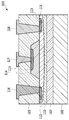
- FIG. 1 shows the structure of a conventional waveguide-coupled vertical GePD.
- FIG. 2 is a sectional view taken along the line II-II in FIG.
- the vertical GePD 100 is formed on a SOI (Silicon On Insulator) substrate including a Si substrate, a Si oxide film, and a surface Si layer by using a lithography technique or the like.
- the vertical GePD 100 includes a Si substrate 101, a lower clad layer 102 made of a Si oxide film on the Si substrate, a core layer 110 for guiding signal light, and a Ge layer 114 for absorbing light formed on the core layer 110. And an upper clad layer 103 formed on the core layer 110 and the Ge layer 114.
- the core layer 110 is divided into a waveguide layer 141 and a silicon slab 142.
- the silicon slab 142 is formed with the p-type Si slab 111 doped with the first conductivity type impurity ions, and the silicon electrode portions 112 and 113 functioning as electrodes by being doped with the first conductivity type impurity ions at a high concentration. ing.
- the Ge layer 114 is stacked by epitaxial growth, and the Ge region 115 doped with the second conductivity type impurity ions is formed on the top thereof.
- the Ge layer 114 may be a germanium compound. Electrodes 116 to 118 are provided on the silicon electrode portions 112 and 113 and the Ge region 115 so as to be in contact with them.
- the cladding layer 103 is omitted, and the electrodes 116 to 118 are shown only at positions in contact with the silicon electrode portions 112 and 113 and the Ge region 115.
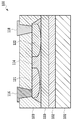
- FIG. 3 shows a first example of a conventional waveguide-coupled lateral GePD.
- a germanium region 121 doped with a first conductivity type impurity ion and a germanium region doped with a second conductivity type impurity ion are used.
- a region 122 is used in the lateral GePD 100.
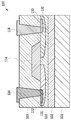
- FIG. 4 shows a second example of a conventional waveguide-coupled lateral GePD.
- lateral GePD 100 instead of the p-type Si slab 111 and the Ge region 115 shown in FIG. 2, a silicon region 131 doped with a first conductivity type impurity ion and a silicon region doped with a second conductivity type impurity ion are used.
- the region 132 and the silicon electrode portion 133 which is highly doped with the second impurity and acts as an electrode are provided.
- FIG. 5 shows the temperature and wavelength dependence characteristics of the sensitivity of the conventional GePD.
- the conventional GePD has a characteristic that the temperature characteristic of sensitivity is not constant.
- the sensitivity is a characteristic of current output with respect to optical input power, and is a unit A/W.
- FIG. 5 is a diagram in which the sensitivity to temperature in the C and L bands (wavelengths 1530 to 1565 nm, 1565 to 1625 nm) of the communication wavelength band is plotted when a reverse bias of 1.6 V is applied to GePD.
- the sensitivity is almost constant up to near the C band, but the sensitivity drops at the L band. This change in sensitivity is caused by a change in the optical absorption spectrum of germanium.
- sensitivity tends to decrease even in the C band.
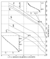
- Figure 6 shows the temperature dependence of the optical absorption spectrum of Ge.
- the horizontal axis is the photon energy, and the vertical axis is the square root of the absorption coefficient (see Non-Patent Document 1, for example).
- the band gap of germanium shifts to the high energy side. That is, the light absorption spectrum edge shifts to the short wavelength side.
- the light absorption spectrum edge of germanium used for GePD is at 1565 nm on the long wavelength side of the C band at 31°C. Therefore, even at a temperature of 31° C., even if the GePD has a constant sensitivity in the entire C band, the sensitivity gradually decreases from the long wavelength side as the temperature decreases. This tendency is shown in FIG. 5, and the longer the wavelength, the lower the sensitivity tends to be at ⁇ 5° C., which is the lower temperature.
- GePD gallium arsphide
- WDM wavelength division multiplexing
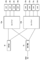
- FIG. 7 shows an example of the configuration of a receiver used in the optical digital coherent communication technology.
- This is a receiver of the polarization multiplexing 4-value phase modulation (DP-QPSK) system, and the received light is separated by a polarization separator 11 into two polarizations orthogonal to each other.
- DP-QPSK polarization multiplexing 4-value phase modulation
- each of the two polarized waves is caused to interfere with the local oscillation light from the local oscillation light source 12 to detect intensity and phase information, and two sets of differential signals are respectively generated by the four GePDs 14 and 15. It is converted into an electrical signal.
- temperature control is performed in such a receiver, it is necessary to provide a heater in each of the Ge PDs 14 and 15.
- GePDs connected to the same optical hybrid receive differential signals in pairs, so that the paired GePDs are required to have uniform sensitivity.
- the photodetector if the sensitivity of a set of GePD groups that receive differential signals is not uniform, the common-mode rejection ratio deteriorates, and the performance of the receiver deteriorates.
- GePD has a manufacturing variation, and this variation may cause the receiver not to meet the in-phase signal rejection ratio specification of the receiver.
- An object of the present invention is to provide a GePD having uniform sensitivity in the C and L bands, and to provide a photodetector in which deterioration of the in-phase signal rejection ratio is suppressed.
- one embodiment of the photodetector according to the present invention includes one or a plurality of sets of two photodiodes to which a differential signal is input, and each of the two photodiodes is provided. Further provided is a monitor connected to measure the photocurrent, and a voltage source controlling the voltage applied to each of the two photodiodes, said voltage source comprising: It is characterized in that the voltage applied to the photodiode is controlled.
- the voltages applied to the photodiodes can be adjusted so that the monitor current values are equal to each other, and the sensitivities of the two photodiodes can be made uniform, so that deterioration of the common-mode rejection ratio can be suppressed. It becomes possible to do.
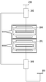
- FIG. 8 shows a photodetector according to an embodiment of the present invention.
- the photodetector includes a set of two GePDs 200 and 201 that receive differential signals, monitors 202 and 203 that detect photocurrents flowing through the GePDs, and power supplies 204 and 205 that apply a voltage to the GePDs.
- the monitors 202 and 203 exchange the detected current value with each other.
- the power supplies 204 and 205 adjust the voltage applied to the GePDs 200 and 201 so that the current values of the monitors 202 and 203 become equal to each other.
- FIG. 9 shows applied voltage dependency of sensitivity of GePD.
- the sensitivity changes as shown in FIG. Therefore, if the applied voltage is adjusted so that the current values of the monitors 202 and 203 are equal to each other, the sensitivities of the two GePDs 200 and 201 can be made uniform.
- the currents measured by the monitors 202 and 203 are photocurrents, and when the current values match, it can be said that the sensitivities of the GePDs 200 and 201 are completely matched. Therefore, in the photodetector of this embodiment, deterioration of the in-phase signal rejection ratio cannot occur.
- the monitor is connected to the cathode side of the GePD, but the monitor may be connected to the anode side connected to the signal output terminal 210.
- FIG. 10 shows a photodetector according to the first embodiment of the present invention.
- Ammeters are connected as monitors 202 and 203 to the cathodes of the GePDs 200 and 201, that is, the cathodes corresponding to the electrodes 117 of the GePD 100 shown in FIG.
- the GePDs 200 and 201 are arranged as a set of GePD pairs that receive differential signals.
- Voltage sources 204 and 205 are connected to the monitors 202 and 203.
- the voltage sources 204 and 205 adjust the voltage applied to the cathode of the GePD so that the photocurrent values measured by the monitors (ammeters) 202 and 203 become equal.
- the monitors 202 and 203 may be connected to the anodes of the GePDs 200 and 201, that is, the anodes corresponding to the electrodes 116 and 118 of the GePD 100 shown in FIG.
- FIG. 11 shows a photodetector according to the second embodiment of the present invention.
- a transimpedance amplifier 220 is connected to the anodes of the GePDs 200 and 201, that is, the anodes corresponding to the electrodes 116 and 118 of the GePD 100 shown in FIG.
- the GePDs 200 and 201 are arranged as a set of GePD pairs that receive differential signals.
- the transimpedance amplifier 220 is an amplifier that converts the current signal of the GePD into a voltage signal, amplifies and outputs the voltage signal, and can monitor the photocurrent from the GePD. This current value is fed back to the voltage sources 204 and 205.
- the voltage sources 204 and 205 adjust the voltage applied to the cathodes of the GePDs 200 and 201 so that the currents input from the GePDs 200 and 201 to the transimpedance amplifier 220 become equal.
- the transimpedance amplifier 220 can also be connected to the cathodes of the GePDs 200 and 201.
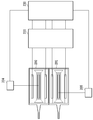
- FIG. 12 shows a photodetector according to the third embodiment of the present invention.
- a transimpedance amplifier 220 is connected to the anodes of the GePDs 200 and 201, that is, the anodes corresponding to the electrodes 116 and 118 of the GePD 100 shown in FIG.
- a digital signal processor 230 is further connected after the transimpedance amplifier 220.
- the GePDs 200 and 201 are arranged as a set of GePD pairs that receive differential signals.
- the digital signal processor 230 monitors the signals input from the GePDs 200 and 201 through the transimpedance amplifier 220, and feeds back to the voltage sources 204 and 205 from this monitor value.
- the voltage sources 204 and 205 adjust the voltage applied to the cathodes of the GePDs 200 and 201 so that the currents input from the GePDs 200 and 201 to the transimpedance amplifier 220 become equal.
- the transimpedance amplifier 220 can also be connected to the cathodes of the GePDs 200 and 201.
Landscapes
- Physics & Mathematics (AREA)
- General Physics & Mathematics (AREA)
- Spectroscopy & Molecular Physics (AREA)
- Light Receiving Elements (AREA)
- Photometry And Measurement Of Optical Pulse Characteristics (AREA)
Abstract
C、L帯において感度の揃ったGePDを提供し、同相信号除去比の劣化が抑制された光検出器を提供する。光検出器の一実施態様は、差動信号が入力される2つのフォトダイオードを、1または複数組備え、前記2つのフォトダイオードの各々に接続され、光電流を測定するモニタ、および前記2つのフォトダイオードの各々に印加する電圧を制御する電圧源をさらに備え、前記電圧源は、前記モニタが測定した光電流が等しくなるように、前記フォトダイオードへの印加電圧を制御する。
Description
本発明は、光検出器に関し、より詳細には、光通信システム、光情報処理システム等において用いられ、差動信号を受信するときの同相信号除去比が小さい光検出器に関する。
近年の光通信の普及に伴い、光通信装置の低コスト化が求められている。その解決策の1つとして、光通信装置を構成する光回路を、大口径のシリコンウエハ上に、シリコンフォトニクスによる微小光回路技術を用いて形成する方法が知られている。これにより、1チップあたりの材料費を劇的に下げ、光通信装置の低コスト化を図ることができる。このような技術を用いて、シリコン(Si)基板上に形成された光検出器として、モノリシック集積が可能なゲルマニウムフォトダイオード(GePD)がある。
図1に、従来の導波路結合型の縦型GePDの構造を示す。図2は、図1の符号II-IIにおける断面図である。縦型のGePD100は、Si基板、Si酸化膜、表面Si層からなるSOI(Silicon On Insulator)基板にリソグラフィ技術等を用いて形成される。縦型のGePD100は、Si基板101と、Si基板上のSi酸化膜からなる下部クラッド層102と、信号光を導くコア層110と、コア層110上に形成された光を吸収するGe層114と、コア層110およびGe層114上に形成された上部クラッド層103を備えている。コア層110は、導波路層141とシリコンスラブ142に分けられる。
シリコンスラブ142は、第一の導電型不純物イオンがドーピングされたp型Siスラブ111、および第一の導電型不純物イオンが高濃度にドーピングされ、電極として作用するシリコン電極部112、113が形成されている。Ge層114は、エピタキシャル成長によって積層され、その上部に第二の導電型不純物イオンがドーピングされたGe領域115が形成されている。Ge層114は、ゲルマニウム化合物であることもある。シリコン電極部112、113およびGe領域115上には、それらに接するように電極116~118を備えている。
なお、構造を分かり易くするために、図1では、クラッド層103を省き、電極116~118は、シリコン電極部112、113およびGe領域115に接する位置のみを示している。
縦型のGePD100は、導波路層141からシリコンスラブ142に光が入射され、Ge層114で光が吸収されると、電極117と電極116、118との間に光電流が流れる。この光電流を検出することにより光を検出する。
図3に、従来の導波路結合型の横型GePDの第1例を示す。横型のGePD100は、図2に示したp型Siスラブ111とGe領域115の代わりに、第一の導電型不純物イオンがドーピングされたゲルマニウム領域121と第二の導電型不純物イオンがドーピングされたゲルマニウム領域122とを備えている。
図4に、従来の導波路結合型の横型GePDの第2例を示す。横型のGePD100は、図2に示したp型Siスラブ111とGe領域115の代わりに、第一の導電型不純物イオンがドーピングされたシリコン領域131と第二の導電型不純物イオンがドーピングされたシリコン領域132と、第二の不純物が高濃度にドーピングされ、電極として作用するシリコン電極部133とを備えている。
図5に、従来のGePDの感度の温度および波長依存特性を示す。従来のGePDは、感度の温度特性が一定ではないという特性がある。ここで、感度とは、光入力パワーに対する電流出力の特性であり、単位A/Wである。図5は、GePDに逆バイアス1.6Vを与えたとき、通信波長帯域のC、L帯(波長1530~1565nm、1565~1625nm)における温度に対する感度をプロットした図である。例えば、31℃ではC帯付近まではほぼ一定の感度を示すが、L帯になると感度が落ちてしまう。この感度変化は、ゲルマニウムの光吸収スペクトルの変化によってもたらされている。-5℃になるとC帯においても感度を落とす傾向を示す。
図6に、Geの光吸収スペクトルの温度依存特性を示す。横軸はフォトンエネルギー、縦軸は吸収係数の平方根である(例えば、非特許文献1参照)。温度が低温になるとゲルマニウムのバンドギャップは、高エネルギー側にシフトする。すなわち、光吸収スペクトル端は短波長側にシフトする。GePDに用いているゲルマニウムの光吸収スペクトル端は、31℃でちょうどC帯の長波長側の1565nm付近にある。従って、31℃ではC帯全域に一定の感度を示すGePDであっても、温度が低くなるにつれ、長波長側から徐々に感度が落ちてゆく。この傾向を示したのが図5であり、長波長ほど低温である-5℃において感度を落とす傾向がある。
温度、波長によって感度が変化するGePDを光通信システムに組み込むためには、感度変化を補償する回路が必要となるため、製造コストが上がる。これを解決する手段として、GePDに印加する電圧を、温度、波長に応じて制御する手段がある(例えば、特許文献1参照)。
一方、GePDを用いた光通信システム、光情報処理システム等の光検出器では、単独のGePDを使うことは少なく、一般に2~8個程度のGePDを並べて使う。これは、多波長を使う波長分割多重(WDM)方式を採用するシステムにおいて波長の数だけGePDを必要としたり、光デジタルコヒーレント通信技術を採用するシステムにおいてバランス型PDとして使うからである。
図7に、光デジタルコヒーレント通信技術において用いる受信機の構成の一例を示す。偏波多重4値位相変調(DP-QPSK)方式の受信機であり、受信光は偏波分離器11により直交する2つの偏波に分離される。2つの偏波のそれぞれを、光ハイブリッド13a,13bにおいて、局発光源12からの局発光と干渉させ、強度と位相の情報が検出され、それぞれ2組の差動信号が4つのGePD14,15により電気信号に変換される。このような受信機において、温度制御を行う場合には、GePD14,15のそれぞれにヒータを備える必要がある。特に、同一の光ハイブリッドに接続されるGePDは、2つ一組で差動信号を受信することから、ペアとなるGePDは、均一の感度が求められる。
Macfarlane G. G., T. P. McLean, J. E. Quarrington and V. Roberts, "fine Structure in the Absorption-Edge Spectrum of Ge," Physical Review vol.108, No.6 (1957) p.1377-1383.
光検出器において、差動信号を受信する一組のGePD群の感度が均一でない場合、同相信号除去比が劣化し、受信機の性能を落とすこととなる。しかしながら、GePDは、製造バラツキを有し、このバラツキが、受信機の同相信号除去比の仕様を満たさない原因となる場合があった。
本発明の目的は、C、L帯において感度の揃ったGePDを提供し、同相信号除去比の劣化が抑制された光検出器を提供することにある。
本発明は、このような目的を達成するために、光検出器の一実施態様は、差動信号が入力される2つのフォトダイオードを、1または複数組備え、前記2つのフォトダイオードの各々に接続され、光電流を測定するモニタ、および前記2つのフォトダイオードの各々に印加する電圧を制御する電圧源をさらに備え、前記電圧源は、前記モニタが測定した光電流が等しくなるように、前記フォトダイオードへの印加電圧を制御することを特徴とする。
本発明によれば、モニタの電流値が互いに等しくなるように、フォトダイオードへの印加電圧を調整して、2つのフォトダイオードの感度を揃えることができるので、同相信号除去比の劣化を抑制することが可能となる。
以下、図面を参照しながら本発明の実施形態について詳細に説明する。
図8に、本発明の一実施形態にかかる光検出器を示す。光検出器は、差動信号を受光する一組2つのGePD200,201と、GePDを流れる光電流をそれぞれ検出するモニタ202,203と、GePDに電圧を印加する電源204,205とを備える。モニタ202,203は、検出した電流値を互いに交換している。モニタ202,203が、GePD200,201を流れる光電流を検出すると、電源204,205は、モニタ202,203の電流値が互いに等しくなるように、GePD200,201に印加する電圧を調整する。
図9に、GePDの感度の印加電圧依存性を示す。C、L帯において使用する波長に対して、GePDに印加する電圧を変化させると、図9に示したように感度が変化する。従って、モニタ202,203の電流値が互いに等しくなるように、印加電圧を調整すれば、2つのGePD200,201の感度を揃えることができる。モニタ202,203が測定する電流は光電流であり、電流値が一致するとき、GePD200,201の感度は完全に合致していると言える。従って、本実施形態の光検出器においては、同相信号除去比の劣化が起きえない。
ここでは、GePDのカソード側にモニタを接続したが、モニタを信号出力用の端子210に接続されるアノード側に接続しても良い。
図10に、本発明の実施例1にかかる光検出器を示す。GePD200,201のカソード、すなわち図1に示したGePD100の電極117に相当するカソードに、それぞれモニタ202,203として電流計が接続されている。GePD200,201は差動信号を受光する一組のGePDペアとして配置してある。モニタ202,203には電圧源204,205が接続されている。
電圧源204,205は、モニタ(電流計)202,203が測定した光電流の電流値が等しくなるように、GePDのカソードに印加する電圧を調整する。なお、モニタ202,203を接続するのは、GePD200,201のアノード、すなわち図1に示したGePD100の電極116,118に相当するアノードであっても良い。
図11に、本発明の実施例2にかかる光検出器を示す。GePD200,201のアノード、すなわち図1に示したGePD100の電極116,118に相当するアノードには、トランスインピーダンスアンプ220が接続されている。GePD200,201は差動信号を受光する一組のGePDペアとして配置してある。
トランスインピーダンスアンプ220は、GePDの電流信号を電圧信号に変換し、増幅して出力するアンプであり、GePDからの光電流をモニタすることができる。この電流値を、電圧源204,205にフィードバックする。電圧源204,205は、GePD200,201からトランスインピーダンスアンプ220に入力される電流が等しくなるように、GePD200,201のカソードに印加する電圧を調整する。なお、トランスインピーダンスアンプ220は、GePD200,201のカソードに接続することもできる。
図12に、本発明の実施例3にかかる光検出器を示す。GePD200,201のアノード、すなわち図1に示したGePD100の電極116,118に相当するアノードには、トランスインピーダンスアンプ220が接続されている。トランスインピーダンスアンプ220の後段には、さらにデジタルシグナルプロセッサ230が接続されている。GePD200,201は差動信号を受光する一組のGePDペアとして配置してある。
デジタルシグナルプロセッサ230は、トランスインピーダンスアンプ220を通してGePD200,201から入力される信号をモニタしており、このモニタ値から電圧源204,205にフィードバックを行う。電圧源204,205は、GePD200,201からトランスインピーダンスアンプ220に入力される電流が等しくなるように、GePD200,201のカソードに印加する電圧を調整する。なお、トランスインピーダンスアンプ220は、GePD200,201のカソードに接続することもできる。
100,200,201 GePD
101 Si基板
102 下部クラッド層
103 上部クラッド層
110 コア層
111 p型Siスラブ
112、113,133 シリコン電極部
114 Ge層
115 Ge領域
116~118 電極
121,122 ゲルマニウム領域
131,132 シリコン領域
141 導波路層
142 シリコンスラブ
202,203 モニタ
204,205 電源
220 トランスインピーダンスアンプ
230 デジタルシグナルプロセッサ
101 Si基板
102 下部クラッド層
103 上部クラッド層
110 コア層
111 p型Siスラブ
112、113,133 シリコン電極部
114 Ge層
115 Ge領域
116~118 電極
121,122 ゲルマニウム領域
131,132 シリコン領域
141 導波路層
142 シリコンスラブ
202,203 モニタ
204,205 電源
220 トランスインピーダンスアンプ
230 デジタルシグナルプロセッサ
Claims (7)
- 差動信号が入力される2つのフォトダイオードを、1または複数組備え、
前記2つのフォトダイオードの各々に接続され、光電流を測定するモニタ、および
前記2つのフォトダイオードの各々に印加する電圧を制御する電圧源をさらに備え、
前記電圧源は、前記モニタが測定した光電流が等しくなるように、前記フォトダイオードへの印加電圧を制御することを特徴とする光検出器。 - 前記フォトダイオードは、
シリコン基板と、
前記シリコン基板上に形成された下部クラッド層と、
前記下部クラッド層上に形成され、第一の導電型不純物イオンがドーピングされたシリコンスラブ、前記第一の導電型不純物イオンが高濃度にドーピングされた電極部、および前記シリコンスラブに接続された導波路層を含むコア層と、
前記コア層上に形成され、第二の導電型不純物がドーピングされたゲルマニウム領域を含むゲルマニウム層と、
前記コア層および前記ゲルマニウム層上に形成された上部クラッド層と、
前記電極部および前記ゲルマニウム領域にそれぞれ接続された電極と
を含むことを特徴とする請求項1に記載の光検出器。 - 前記フォトダイオードは、
シリコン基板と、
前記シリコン基板上に形成された下部クラッド層と、
前記下部クラッド層上に形成され、第一の導電型不純物イオンがドーピングされたシリコンスラブ、および前記シリコンスラブに接続された導波路層を含むコア層と、
前記コア層上に形成され、第一の導電型不純物イオンがドーピングされた第一のゲルマニウム領域、および第二の導電型不純物イオンがドーピングされた第二のゲルマニウム領域を含むゲルマニウム層と、
前記コア層および前記ゲルマニウム層上に形成された上部クラッド層と、
前記第一および前記第二のゲルマニウム領域にそれぞれ接続された電極と
を含むことを特徴とする請求項1に記載の光検出器。 - 前記フォトダイオードは、
シリコン基板と、
前記シリコン基板上に形成された下部クラッド層と、
前記下部クラッド層上に形成され、第一の導電型不純物イオンがドーピングされた第一のシリコン領域および前記第一の導電型不純物イオンがドーピングされた第一の電極部、並びに、第二の導電型不純物イオンがドーピングされた第二のシリコン領域、および前記第二の導電型不純物イオンがドーピングされた第二の電極部を含むシリコンスラブと、前記シリコンスラブに接続された導波路層とを含むコア層と、
前記コア層上に形成されたゲルマニウム層と、
前記コア層および前記ゲルマニウム層上に形成された上部クラッド層と、
前記第一および前記第二の電極部に接続された電極と
を含むことを特徴とする請求項1に記載の光検出器。 - 前記モニタは、前記フォトダイオードのアノードまたはカソードに接続された電流計であることを特徴とする請求項1に記載の光検出器。
- 前記モニタは、前記フォトダイオードのアノードまたはカソードに接続されたトランスインピーダンスアンプであることを特徴とする請求項1に記載の光検出器。
- 前記モニタとは、前記トランスインピーダンスアンプに接続されたデジタルシグナルプロセッサであることを特徴とする請求項6に記載の光検出器。
Priority Applications (1)
| Application Number | Priority Date | Filing Date | Title |
|---|---|---|---|
| US17/422,022 US11543293B2 (en) | 2019-01-16 | 2020-01-15 | Photodetector |
Applications Claiming Priority (2)
| Application Number | Priority Date | Filing Date | Title |
|---|---|---|---|
| JP2019005493A JP2020113715A (ja) | 2019-01-16 | 2019-01-16 | 光検出器 |
| JP2019-005493 | 2019-01-16 |
Publications (1)
| Publication Number | Publication Date |
|---|---|
| WO2020149276A1 true WO2020149276A1 (ja) | 2020-07-23 |
Family
ID=71613898
Family Applications (1)
| Application Number | Title | Priority Date | Filing Date |
|---|---|---|---|
| PCT/JP2020/000954 Ceased WO2020149276A1 (ja) | 2019-01-16 | 2020-01-15 | 光検出器 |
Country Status (3)
| Country | Link |
|---|---|
| US (1) | US11543293B2 (ja) |
| JP (1) | JP2020113715A (ja) |
| WO (1) | WO2020149276A1 (ja) |
Cited By (1)
| Publication number | Priority date | Publication date | Assignee | Title |
|---|---|---|---|---|
| WO2022029942A1 (ja) * | 2020-08-05 | 2022-02-10 | 日本電信電話株式会社 | 光受信機 |
Families Citing this family (1)
| Publication number | Priority date | Publication date | Assignee | Title |
|---|---|---|---|---|
| US12433056B2 (en) * | 2021-12-20 | 2025-09-30 | Intel Corporation | Planar germanium photodetector |
Citations (8)
| Publication number | Priority date | Publication date | Assignee | Title |
|---|---|---|---|---|
| JPH04192378A (ja) * | 1990-11-24 | 1992-07-10 | Shimadzu Corp | 光受信回路 |
| JPH11135822A (ja) * | 1997-10-29 | 1999-05-21 | Nippon Telegr & Teleph Corp <Ntt> | 受光回路 |
| WO2005013517A2 (en) * | 2003-07-30 | 2005-02-10 | Denselight Semiconductors Pte Ltd. | Optical transceiver with reduced optical cross-talk between transmitter and receiver |
| WO2008099507A1 (ja) * | 2007-02-16 | 2008-08-21 | Fujitsu Limited | 光受信装置 |
| JP2014146737A (ja) * | 2013-01-30 | 2014-08-14 | Nippon Telegr & Teleph Corp <Ntt> | フォトダイオードアレイおよびその製造方法 |
| JP2015153899A (ja) * | 2014-02-14 | 2015-08-24 | 日本電信電話株式会社 | 受光素子の制御方法 |
| JP2016025513A (ja) * | 2014-07-22 | 2016-02-08 | 日本電信電話株式会社 | コヒーレント光受信機 |
| JP2018195654A (ja) * | 2017-05-15 | 2018-12-06 | 日本電信電話株式会社 | 光検出器 |
Family Cites Families (6)
| Publication number | Priority date | Publication date | Assignee | Title |
|---|---|---|---|---|
| US7659981B2 (en) * | 2005-08-26 | 2010-02-09 | Dcg Systems, Inc. | Apparatus and method for probing integrated circuits using polarization difference probing |
| US8306419B2 (en) * | 2009-06-11 | 2012-11-06 | Lg-Ericsson Co., Ltd. | Techniques for controlling a light source in a wavelength division multiplexed passive optical network |
| WO2013180690A1 (en) * | 2012-05-29 | 2013-12-05 | Hewlett-Packard Development Company, L.P. | Devices including independently controllable absorption region and multiplication region electric fields |
| WO2015187222A2 (en) * | 2014-03-10 | 2015-12-10 | Coriant Advanced Technology, LLC | Germanium metal-contact-free near-ir photodetector |
| JP5927359B2 (ja) * | 2014-06-02 | 2016-06-01 | オリンパス株式会社 | 照明装置 |
| US9638874B2 (en) * | 2014-10-17 | 2017-05-02 | Samtec, Inc. | Methods for determining receiver coupling efficiency, link margin, and link topology in active optical cables |
-
2019
- 2019-01-16 JP JP2019005493A patent/JP2020113715A/ja active Pending
-
2020
- 2020-01-15 WO PCT/JP2020/000954 patent/WO2020149276A1/ja not_active Ceased
- 2020-01-15 US US17/422,022 patent/US11543293B2/en active Active
Patent Citations (8)
| Publication number | Priority date | Publication date | Assignee | Title |
|---|---|---|---|---|
| JPH04192378A (ja) * | 1990-11-24 | 1992-07-10 | Shimadzu Corp | 光受信回路 |
| JPH11135822A (ja) * | 1997-10-29 | 1999-05-21 | Nippon Telegr & Teleph Corp <Ntt> | 受光回路 |
| WO2005013517A2 (en) * | 2003-07-30 | 2005-02-10 | Denselight Semiconductors Pte Ltd. | Optical transceiver with reduced optical cross-talk between transmitter and receiver |
| WO2008099507A1 (ja) * | 2007-02-16 | 2008-08-21 | Fujitsu Limited | 光受信装置 |
| JP2014146737A (ja) * | 2013-01-30 | 2014-08-14 | Nippon Telegr & Teleph Corp <Ntt> | フォトダイオードアレイおよびその製造方法 |
| JP2015153899A (ja) * | 2014-02-14 | 2015-08-24 | 日本電信電話株式会社 | 受光素子の制御方法 |
| JP2016025513A (ja) * | 2014-07-22 | 2016-02-08 | 日本電信電話株式会社 | コヒーレント光受信機 |
| JP2018195654A (ja) * | 2017-05-15 | 2018-12-06 | 日本電信電話株式会社 | 光検出器 |
Cited By (1)
| Publication number | Priority date | Publication date | Assignee | Title |
|---|---|---|---|---|
| WO2022029942A1 (ja) * | 2020-08-05 | 2022-02-10 | 日本電信電話株式会社 | 光受信機 |
Also Published As
| Publication number | Publication date |
|---|---|
| US20220099486A1 (en) | 2022-03-31 |
| US11543293B2 (en) | 2023-01-03 |
| JP2020113715A (ja) | 2020-07-27 |
Similar Documents
| Publication | Publication Date | Title |
|---|---|---|
| US10411149B2 (en) | Lateral avalanche photodetector | |
| US20100054761A1 (en) | Monolithic coherent optical detectors | |
| JP5232981B2 (ja) | SiGeフォトダイオード | |
| WO2010021669A2 (en) | Monolithic coherent optical detectors | |
| Xie et al. | InGaAs/InAlAs avalanche photodiode with low dark current for high-speed operation | |
| WO2017023301A1 (en) | Lateral ge/si avalanche photodetector | |
| US20240347665A1 (en) | Avalanche photodiodes with lower excess noise and lower bandwidth variation | |
| US11543293B2 (en) | Photodetector | |
| Beling et al. | High-speed miniaturized photodiode and parallel-fed traveling-wave photodetectors based on InP | |
| US11769849B2 (en) | Photodetector | |
| Takeda et al. | Contributions of Franz–Keldysh and Avalanche Effects to Responsivity of a Germanium Waveguide Photodiode in the $\hbox {L} $-Band | |
| JP6726248B2 (ja) | 半導体受光素子、及び光電融合モジュール | |
| US11887999B2 (en) | Photodetector | |
| US12087800B2 (en) | Photodector including germanium layer and doped region | |
| JP6362142B2 (ja) | ゲルマニウム受光器 | |
| CN111543017A (zh) | 平衡半导体光波导中的损耗 | |
| US12119419B2 (en) | Photodetector | |
| Hon et al. | Design and performance of high-speed Ge-on-Si waveguide photodiodes | |
| Nakanishi et al. | 4× 28 Gbaud PAM4 integrated ROSA with high-sensitivity APD | |
| Ackert et al. | 10 Gb/s bit error free performance of a monolithic silicon avalanche waveguide-integrated photodetector | |
| Nakajima et al. | High-speed avalanche photodiode for 100-gbit/s ethernet | |
| WO2020149264A1 (ja) | 光検出器 | |
| DeCusatis et al. | Detectors for Fiber Optics |
Legal Events
| Date | Code | Title | Description |
|---|---|---|---|
| 121 | Ep: the epo has been informed by wipo that ep was designated in this application |
Ref document number: 20741879 Country of ref document: EP Kind code of ref document: A1 |
|
| NENP | Non-entry into the national phase |
Ref country code: DE |
|
| 122 | Ep: pct application non-entry in european phase |
Ref document number: 20741879 Country of ref document: EP Kind code of ref document: A1 |