WO2020149140A1 - 車載用イメージング装置、車両用灯具、自動車 - Google Patents
車載用イメージング装置、車両用灯具、自動車 Download PDFInfo
- Publication number
- WO2020149140A1 WO2020149140A1 PCT/JP2019/051193 JP2019051193W WO2020149140A1 WO 2020149140 A1 WO2020149140 A1 WO 2020149140A1 JP 2019051193 W JP2019051193 W JP 2019051193W WO 2020149140 A1 WO2020149140 A1 WO 2020149140A1
- Authority
- WO
- WIPO (PCT)
- Prior art keywords
- vehicle
- intensity
- imaging device
- period
- light
- Prior art date
- Legal status (The legal status is an assumption and is not a legal conclusion. Google has not performed a legal analysis and makes no representation as to the accuracy of the status listed.)
- Ceased
Links
Images



Classifications
-
- B—PERFORMING OPERATIONS; TRANSPORTING
- B60—VEHICLES IN GENERAL
- B60Q—ARRANGEMENT OF SIGNALLING OR LIGHTING DEVICES, THE MOUNTING OR SUPPORTING THEREOF OR CIRCUITS THEREFOR, FOR VEHICLES IN GENERAL
- B60Q1/00—Arrangement of optical signalling or lighting devices, the mounting or supporting thereof or circuits therefor
- B60Q1/02—Arrangement of optical signalling or lighting devices, the mounting or supporting thereof or circuits therefor the devices being primarily intended to illuminate the way ahead or to illuminate other areas of way or environments
- B60Q1/04—Arrangement of optical signalling or lighting devices, the mounting or supporting thereof or circuits therefor the devices being primarily intended to illuminate the way ahead or to illuminate other areas of way or environments the devices being headlights
- B60Q1/14—Arrangement of optical signalling or lighting devices, the mounting or supporting thereof or circuits therefor the devices being primarily intended to illuminate the way ahead or to illuminate other areas of way or environments the devices being headlights having dimming means
- B60Q1/1415—Dimming circuits
- B60Q1/1423—Automatic dimming circuits, i.e. switching between high beam and low beam due to change of ambient light or light level in road traffic
- B60Q1/143—Automatic dimming circuits, i.e. switching between high beam and low beam due to change of ambient light or light level in road traffic combined with another condition, e.g. using vehicle recognition from camera images or activation of wipers
-
- B—PERFORMING OPERATIONS; TRANSPORTING
- B60—VEHICLES IN GENERAL
- B60Q—ARRANGEMENT OF SIGNALLING OR LIGHTING DEVICES, THE MOUNTING OR SUPPORTING THEREOF OR CIRCUITS THEREFOR, FOR VEHICLES IN GENERAL
- B60Q1/00—Arrangement of optical signalling or lighting devices, the mounting or supporting thereof or circuits therefor
- B60Q1/02—Arrangement of optical signalling or lighting devices, the mounting or supporting thereof or circuits therefor the devices being primarily intended to illuminate the way ahead or to illuminate other areas of way or environments
- B60Q1/04—Arrangement of optical signalling or lighting devices, the mounting or supporting thereof or circuits therefor the devices being primarily intended to illuminate the way ahead or to illuminate other areas of way or environments the devices being headlights
-
- G—PHYSICS
- G01—MEASURING; TESTING
- G01S—RADIO DIRECTION-FINDING; RADIO NAVIGATION; DETERMINING DISTANCE OR VELOCITY BY USE OF RADIO WAVES; LOCATING OR PRESENCE-DETECTING BY USE OF THE REFLECTION OR RERADIATION OF RADIO WAVES; ANALOGOUS ARRANGEMENTS USING OTHER WAVES
- G01S17/00—Systems using the reflection or reradiation of electromagnetic waves other than radio waves, e.g. lidar systems
- G01S17/88—Lidar systems specially adapted for specific applications
- G01S17/89—Lidar systems specially adapted for specific applications for mapping or imaging
-
- G—PHYSICS
- G01—MEASURING; TESTING
- G01S—RADIO DIRECTION-FINDING; RADIO NAVIGATION; DETERMINING DISTANCE OR VELOCITY BY USE OF RADIO WAVES; LOCATING OR PRESENCE-DETECTING BY USE OF THE REFLECTION OR RERADIATION OF RADIO WAVES; ANALOGOUS ARRANGEMENTS USING OTHER WAVES
- G01S7/00—Details of systems according to groups G01S13/00, G01S15/00, G01S17/00
- G01S7/48—Details of systems according to groups G01S13/00, G01S15/00, G01S17/00 of systems according to group G01S17/00
- G01S7/483—Details of pulse systems
- G01S7/486—Receivers
- G01S7/4861—Circuits for detection, sampling, integration or read-out
Definitions
- the present invention relates to a vehicle-mounted imaging device.
- An object identification system that senses the position and type of objects existing around the vehicle is used for automatic driving and automatic control of headlamp light distribution.
- the object identification system includes a sensor and an arithmetic processing unit that analyzes the output of the sensor.
- the sensor is selected from cameras, LiDAR (Light Detection and Ranging, Laser Imaging Detection and Ranging), millimeter wave radar, ultrasonic sonar, etc., in consideration of application, required accuracy and cost.
- the imaging devices As one of the imaging devices (sensors), one that uses the principle of ghost imaging is known.
- ghost imaging an object is irradiated while randomly switching the intensity distribution (pattern) of reference light, and the light detection intensity of reflected light is measured in association with each random pattern.
- the photodetection intensity is an integrated value of energy or intensity over a plane, not an intensity distribution. Then, the reconstructed image of the object is reconstructed by taking the correlation between the corresponding pattern and the light detection intensity.
- the distance between the imaging device and the subject is approximately constant, in other words, the range in the depth direction in which the subject exists is significantly limited.
- the interval (pause period) between the random patterns of the reference light be as short as possible, but the range in which the subject exists is narrow. If the interval is short, no problem will occur.
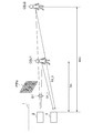
- FIG. 1 is a diagram illustrating measurement of an object by a conventional imaging device 1.
- the illumination device 2 randomly switches the pattern PTN of the reference light S1 at very short intervals (substantially zero). For example, when the switching frequency of the pattern is 400 Hz, one pattern lasts for an irradiation time T ILM of 2 ms.
- the photodetector 4 measures the reflected lights S2_1 and S2_2 from the objects OBJ1 and OBJ2 during a predetermined detection period (exposure time or integration period) T DET .
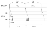
- FIG. 2 is a time chart explaining the operation of the imaging apparatus 1 in the situation of FIG.
- the farther the object is the more the reference light S1 emitted at the same timing is reflected by the object OBJ and the time (round trip time) until the reflected light S2 reaches the photodetector 4 is longer. become longer.
- the distances to the object OBJ1 and the object OBJ2 are 1.5 m and 60 m, respectively, and the round trip time of light is 10 ns and 400 ns. Therefore, the reflected light S2_2 enters the photodetector 4 later than the reflected light S2_1.
- the component (hatched) of the reflected light S2_2 reflected by the past pattern PTN 1 on the object OBJ2 is detected. That is, random patterns that are temporally adjacent to each other interfere with each other, which causes deterioration of image quality.
- the present invention has been made in such a situation, and one of the illustrative purposes of a certain aspect thereof is to improve the image quality in an in-vehicle imaging device.
- the on-vehicle imaging device is a lighting device that emits a reference light having a random pattern that switches for each irradiation period, a photodetector that measures reflected light from an object, and a detection intensity based on a detection signal output by the photodetector. And an arithmetic processing unit for reconstructing a restored image of the object by taking a correlation of the intensity distribution of the reference light.
- An interval period in which the intensity is zero or the spatial intensity distribution is uniform is inserted between the irradiation periods, and the upper limit of the sensing distance in the depth direction of the in-vehicle imaging device is L MAX , the speed of light is inserted between the irradiation periods.
- L MAX the upper limit of the sensing distance in the depth direction of the in-vehicle imaging device
- the arithmetic processing unit may use the detection intensity obtained in the period when the detection signal is larger than the threshold value for the reconstruction of the restored image.
- the processing unit may start the detection period when the detection signal exceeds the threshold value.
- the detection intensity used for the correlation calculation is generated based on the detection signal obtained during the detection period. Since the rise of the detection signal represents the arrival of the reflected light from the closest object, by using it as the trigger to start the generation of the detection intensity, it is possible to reduce the intake of extra light and eventually the influence of noise etc. ..
- the arithmetic processing unit may end the detection period when the detection signal falls below the threshold value.
- the fall of the detection signal represents the arrival of the reflected light from the furthest object, so by using it as a trigger for ending the generation of the detection intensity, it is possible to reduce the intake of extra light and eventually reduce the effects of noise and the like. ..
- the threshold value may be set based on the detection signal obtained in the interval period.
- the intensity of the reference light may be zero during the interval period.
- the arithmetic processing device may correct the detection intensity used for reconstruction of the restored image using the detection signal obtained in the interval period. Since the detection signal obtained in the interval period is a noise component due to ambient light, the influence of ambient light can be reduced and the image quality can be improved by correcting the detection intensity corresponding to the random pattern using the noise component.
- the length of the irradiation period and the length of the interval period may be the same. In this case, the noise correction process can be simplified.
- the image quality of the vehicle-mounted imaging device can be improved.
- FIG. 3 is a time chart explaining the operation of the imaging apparatus in the situation of FIG. 1. It is a figure which shows the imaging device which concerns on embodiment. It is a figure explaining the measurement of the object by an imaging device.
- 6 is a time chart illustrating the operation of the imaging apparatus.
- 9 is a time chart illustrating the operation of the imaging apparatus according to the first modification. 9 is a time chart explaining the operation of the imaging apparatus according to the second modification.
- It is a block diagram of an object identification system. 1 is a block diagram of an automobile including an object identification system. It is a block diagram which shows the vehicle lamp provided with an object detection system.
- the intensity distribution is random in the present specification does not mean that it is completely random, but may be random as long as an image can be reconstructed in ghost imaging. Therefore, “random” in the present specification can include a certain degree of regularity therein. Also, “random” does not require to be completely unpredictable, but may be predictable and reproducible.
- FIG. 3 is a diagram showing an imaging device 100 according to the embodiment.
- the imaging device 100 is an image sensor that uses the principle of ghost imaging, and includes an illumination device 110, a photodetector 120, and an arithmetic processing device 130.
- the imaging device 100 is also called a quantum radar camera.
- the lighting device 110 is a pseudo heat light source, and generates the reference light S1 having the intensity distribution I(x, y) that can be regarded as substantially random, and irradiates the object OBJ.
- the irradiation of the reference light S1 to the object OBJ is performed while randomly changing the intensity distribution thereof a plurality of M times.
- the lighting device 110 includes a light source 112, a patterning device 114, and a pattern generator 132.
- the light source 112 generates the light S0 having a uniform intensity distribution.
- the light source 112 may use a laser, a light emitting diode, or the like.
- the wavelength and spectrum of the reference light S1 are not particularly limited, and may be white light having a plurality of or continuous spectra, or monochromatic light having a predetermined wavelength.
- the wavelength of the reference light S1 may be infrared or ultraviolet.
- the patterning device 114 has a plurality of pixels arranged in a matrix, and the light intensity distribution I can be spatially modulated based on a combination of ON and OFF of the plurality of pixels.
- a pixel in an on state is referred to as an on pixel
- a pixel in an off state is referred to as an off pixel. Note that, in the following description, for ease of understanding, each pixel takes only two values (1, 0) of ON and OFF, but the present invention is not limited to this and may take an intermediate gradation.
- a reflective DMD Digital Micromirror Device
- a transmissive liquid crystal device can be used as the patterning device 114.
- a pattern signal PTN (image data) generated by the pattern generator 132 is applied to the patterning device 114.
- the photodetector 120 measures the reflected light from the object OBJ and outputs a detection signal D r .
- the detection signal D r is a spatial integral value of light energy (or intensity) incident on the photodetector 120 when the object OBJ is irradiated with the reference light having the intensity distribution I r . Therefore, the photodetector 120 can use a single-pixel photodetector (photodetector).
- the photodetector 120 outputs a plurality of detection signals D 1 to D M corresponding to a plurality of M intensity distributions I 1 to I M, respectively.
- the arithmetic processing unit 130 includes a pattern generator 132 and a reconstruction processing unit 134.
- the reconstruction processing unit 134 correlates a plurality of intensity distributions (also referred to as random patterns) I 1 to I M and a plurality of detected intensities b 1 to b M to obtain a restored image G(x,y of the object OBJ. ) Is reconfigured.
- the detection intensities b 1 to b M are based on the detection signals D 1 to D M.
- the relationship between the detection intensity and the detection signal may be determined in consideration of the type and method of the photodetector 120.
- the detection signal D r is assumed to represent the amount of received light at a certain time (or a minute time), that is, an instantaneous value.
- the detection signal D r is sampled a plurality of times in the detection period T DET corresponding to the irradiation period T ILM , and the detection intensity b r may be an integrated value, an average value, or a maximum value of all sampling values of the detection signal D r. Good. Alternatively, some of all the sampling values may be selected, and the integrated value, average value, or maximum value of the selected sampling values may be used.
- the xth to yth order counting from the maximum value may be extracted, sampling values lower than an arbitrary threshold value may be excluded, or the magnitude of signal fluctuation may be excluded. It is also possible to extract a sampling value in a range where is smaller.
- the output D r of the photodetector 120 is used as it is as the detection intensity b r.
- the conversion from the detection signal D r to the detection intensity b r may be performed by the arithmetic processing device 130 or may be performed outside the arithmetic processing device 130.
- I r is the r-th intensity distribution
- b r is the r-th detected intensity value
- the processor 130 can be implemented by a combination of a processor (hardware) such as a CPU (Central Processing Unit), an MPU (Micro Processing Unit), and a microcomputer, and a software program executed by the processor (hardware).
- a processor such as a CPU (Central Processing Unit), an MPU (Micro Processing Unit), and a microcomputer
- the arithmetic processing unit 130 may be a combination of a plurality of processors. Alternatively, the arithmetic processing unit 130 may be composed of only hardware.
- an interval period in which the spatial intensity distribution is zero (that is, all pixels are off) is inserted between the random patterns.
- the interval period T INT is determined to be longer than 2 ⁇ L MAX /c, where L MAX is the upper limit of the sensing distance in the depth direction of the imaging apparatus 100 and c is the speed of light.
- the above is the configuration of the imaging apparatus 100. Next, the operation will be described.
- FIG. 4 is a diagram illustrating measurement of the object OBJ by the imaging device 100.
- the measurement range in the depth direction of the imaging device 100 is limited to L MIN to L MAX as a specification.
- the length of the interval period T INT is set equal to or longer than the maximum round trip time T MAX .
- FIG. 5 is a time chart explaining the operation of the imaging apparatus 100.
- the random pattern PTN 1 is irradiated during the time t 1 to t 2 .
- the reference light S1 that has left the illumination device 110 at time t 1 is reflected by the object OBJ1 in the foreground, and returns to the photodetector 120 as reflected light S2_1 at time t 3 after the elapse of T MIN from time t 1 .
- the reference light S1 that has left the illumination device 110 at time t 1 is reflected by the object OBJ2 on the back side, and returns to the photodetector 120 as reflected light S2_2 at time t 4 after the elapse of T MAX from time t 1 .
- Reference beam S1 the time t 2 set out the illumination device 110 is reflected in front of the object OBJ1, returns to the optical detector 120 as reflected light S2_1 from time t 2 to time t 5 after T MIN passed.
- Reference beam S1 the time t 2 set out the illumination device 110 is reflected by the object OBJ2 on the back side, returns to the optical detector 120 as reflected light S2_2 from time t 2 to time t 6 after T MAX has elapsed.
- T INT can be set longer than T MAX .
- T MAX 400 ns
- T INT 0.5 ms may be set.
- the reflected light S2_2 of the object OBJ2 returns to the photodetector 120 before time t 7 . Therefore, if the detection period T DET1 is set between the periods t 1 to t 7 , the reflected lights S2_1 and S2_2 based on only the same random pattern PTN 1 are detected. In other words, it is possible to remove the interference of random patterns that are temporally adjacent to each other, and improve the image quality.
- the start point of the detection period T DET in each detection cycle may be set between t 1 and t 3
- the end point of the detection period T DET may be set between t 6 and t 7 .
- the length of the interval period T INT may be longer than T MAX ⁇ T MIN .
- the starting point of the detection period T DET may be dynamically determined according to the distance to the object OBJ. Specifically, the time when the reflected light from the object OBJ closest to the imaging device 100 reaches the photodetector 120 may be set as the starting point of the detection period T DET .
- FIG. 6 is a time chart explaining the operation of the imaging apparatus 100 according to the first modification. It is assumed that the reference light S1 is completely turned off during the interval period T INT . Then, during the interval period T INT, the reflected light S2 does not enter the illumination device 110, and only ambient light (disturbance noise) enters. That is, it can be said that the detection signal D in the interval period T INT is smaller than the period in which the reflected light S2 of the random pattern is incident. In other words, the detection signal D rapidly rising at a certain time indicates that the reflected light S2 from the object OBJ is incident on the photodetector 120.
- the arithmetic processing unit 130 monitors the output signal D of the photodetector 120 and sets the timing at which the noise level has increased from the significant signal level to the start point of the detection period T DET .
- the arithmetic processing unit 130 may set the threshold value TH between the noise level and the significant signal level, and start the detection period T DET when D>TH.
- the arithmetic processing unit 130 may monitor the output signal D of the photodetector 120 and set the timing at which the signal level drops from the significant signal level to the noise level as the end point of the detection period T DET .
- the arithmetic processing unit 130 may end the detection period T DET when D ⁇ TH.
- the arithmetic processing unit 130 samples and captures the detection signal D during the detection period T DETr set in this way, and generates the detection intensity b r based on a plurality of sampling values.
- the arithmetic processing unit 130 may dynamically change the threshold value TH. For example, during the interval period T INT, provided the noise detection period T NS for sensing noise, the detection signal D measured in the noise detection period T NS, and the noise level, on the basis of the noise level, following
- the threshold value TH for the detection period T DET may be set.
- the noise level may be offset by a predetermined width to obtain the threshold TH, or the noise level may be multiplied by a predetermined number to obtain the threshold TH.
- the first modification it is possible to reduce the intake of extra light and eventually reduce the influence of noise and the like.
- FIG. 7 is a time chart explaining the operation of the imaging apparatus 100 according to the second modification. Also in the second modification, the intensity of the reference light S1 in the interval period T INT is zero.
- a noise detection period TNS is provided during a period (referred to as a non-detection period) during which the reflected light S2 does not return, the noise level of the detection signal D is measured, and the detection signal D and thus the detection intensity are detected based on the measured noise level.
- the detection period T DET may be set using the technique of the first modification, and the rest may be set as the non-detection period.
- the value (that is, the noise level) of the detection signal D sampled in the noise detection period T NS is subtracted from the detection signal D sampled in the detection period T DET , and the detection intensity b is calculated based on the detection signal D after the subtraction. You may generate r .
- the values of the detection signals D sampled in the noise detection period T NS are integrated, and the noise correction value N is generated based on the integrated value. Further, the detection signals D sampled in the detection period T DET are integrated to generate the detection intensity b r including noise. Then, the corrected detection intensity b r may be generated by subtracting the noise correction value N from the detection intensity b r including noise.
- the noise correction value N is scaled based on the ratio of the lengths of the detection period T DET and the noise detection period T NS .
- the irradiation period T ILM and the interval period T INT may be set to have the same length.
- the detection period T DET and the non-detection period can have the same length.
- the non-detection period may be the noise detection period T NS .
- the detection period T DET and the noise detection period T NS are equal to each other, scaling of the noise correction value N is unnecessary, and therefore the process can be simplified.
- FIG. 8 is a block diagram of the object identification system 10.
- the object identification system 10 is mounted on a vehicle such as an automobile or a motorcycle, and determines the type (category) of an object OBJ existing around the vehicle.
- the object identification system 10 includes an imaging device 100 and an arithmetic processing device 40. As described above, the imaging apparatus 100 irradiates the object OBJ with the reference light S1 and measures the reflected light S2 to generate the restored image G of the object OBJ.
- the arithmetic processing device 40 processes the output image G of the imaging device 100 and determines the position and type (category) of the object OBJ.
- the classifier 42 of the arithmetic processing device 40 receives the image G as an input and determines the position and type of the object OBJ included in the image G.
- the classifier 42 is implemented based on the model generated by machine learning.
- the algorithm of the classifier 42 is not particularly limited, but YOLO (You Only Look Once), SSD (Single Shot Multi Box Detector), R-CNN (Region-based Convolutional Neural Network), SPPnet (Spatial Pyramid Pooling), Faster R-CNN , DSSD (Deconvolution-SSD), MaskR-CNN, etc. can be adopted, or an algorithm developed in the future can be adopted.
- the imaging device 100 that is, a quantum radar camera
- noise resistance is significantly increased.
- the imaging device 100 that is, a quantum radar camera
- the object OBJ is not affected by rain, snow, or fog.
- the restored image G can be obtained.
- the imaging apparatus 100 since the imaging apparatus 100 according to the embodiment is used, it is possible to prevent interference between random patterns that are temporally adjacent to each other and improve image quality.
- FIG. 9 is a block diagram of an automobile including the object identification system 10.
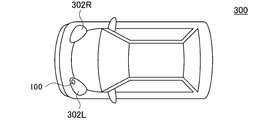
- the automobile 300 includes headlights 302L and 302R.
- the imaging device 100 is built in at least one of the headlights 302L and 302R.
- the headlight 302 is located at the most tip of the vehicle body, and is most advantageous as an installation location of the imaging apparatus 100 in detecting surrounding objects.
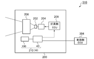
- FIG. 10 is a block diagram showing a vehicular lamp 200 including an object detection system 210.
- the vehicle lamp 200 constitutes a lamp system 310 together with the vehicle-side ECU 304.
- the vehicular lamp 200 includes a light source 202, a lighting circuit 204, and an optical system 206. Further, the vehicle lighting device 200 is provided with an object detection system 210.
- the object detection system 210 corresponds to the above-described object identification system 10, and includes the imaging device 100 and the arithmetic processing device 40.
- Information about the object OBJ detected by the arithmetic processing unit 40 may be used for light distribution control of the vehicular lamp 200.
- the lamp-side ECU 208 generates an appropriate light distribution pattern based on the information on the type and the position of the object OBJ generated by the arithmetic processing device 40.
- the lighting circuit 204 and the optical system 206 operate so as to obtain the light distribution pattern generated by the lamp-side ECU 208.
- Information regarding the object OBJ detected by the arithmetic processing unit 40 may be transmitted to the vehicle-side ECU 304.
- the vehicle-side ECU may perform automatic driving based on this information.
- the illumination device 110 is composed of the combination of the light source 112 and the patterning device 114, but it is not limited thereto.
- the illuminating device 110 is configured by an array of a plurality of semiconductor light sources (LED (light emitting diode) or LD (laser diode)) arranged in a matrix, and ON/OFF (or brightness) of each semiconductor light source can be controlled. You may comprise.
- the method using correlation calculation has been described as the ghost imaging (or single pixel imaging) method, but the image reconstruction method is not limited thereto.
- an analytical method using Fourier transform or Hadamard inverse transform a method for solving an optimization problem such as sparse modeling, and an algorithm using AI/machine learning, The image may be reconstructed.
- the present invention relates to a vehicle-mounted imaging device.
- OBJ object 10 object identification system 40 arithmetic processing device 42 classifier 100 imaging device 110 illumination device 112 light source 114 patterning device 120 photodetector 130 arithmetic processing device 132 pattern generator 134 reconstruction processing unit 200 vehicle lamp 202 light source 204 lighting circuit 206 Optical system 300 Automobile 302 Headlight 310 Lighting system 304 Vehicle side ECU
Landscapes
- Engineering & Computer Science (AREA)
- Physics & Mathematics (AREA)
- Computer Networks & Wireless Communication (AREA)
- General Physics & Mathematics (AREA)
- Radar, Positioning & Navigation (AREA)
- Remote Sensing (AREA)
- Mechanical Engineering (AREA)
- Electromagnetism (AREA)
- Optical Radar Systems And Details Thereof (AREA)
- Measurement Of Optical Distance (AREA)
Abstract
照明装置110は、照射期間TILMごとに切り替わるランダムパターンを有する参照光S1を物体OBJに照射する。光検出器120は、物体OBJからの反射光S2を測定する。演算処理装置130は、光検出器120の出力Dにもとづく検出強度bと参照光の強度分布にもとづいて、物体OBJの復元画像を再構成する。ひとつのランダムパターンPTNに対応する照射期間TILMと、次のランダムパターンPTNに対応する照射期間TILMの間に、強度がゼロまたは強度分布が均一であるインターバル期間TINTが挿入される。車載用イメージング装置100の奥行き方向のセンシング距離の上限をLMAX、光速をcとするとき、インターバル期間TINTは2×LMAX/c以上である。
Description
本発明は、車載用イメージング装置に関する。
自動運転やヘッドランプの配光の自動制御のために、車両の周囲に存在する物体の位置および種類をセンシングする物体識別システムが利用される。物体識別システムは、センサと、センサの出力を解析する演算処理装置を含む。センサは、カメラ、LiDAR(Light Detection and Ranging、Laser Imaging Detection and Ranging)、ミリ波レーダ、超音波ソナーなどの中から、用途、要求精度やコストを考慮して選択される。
イメージング装置(センサ)のひとつとして、ゴーストイメージングの原理を利用したものが知られている。ゴーストイメージングは、参照光の強度分布(パターン)をランダムに切り替えながら物体に照射し、各ランダムパターンと対応付けて、反射光の光検出強度を測定する。光検出強度はある平面にわたるエネルギーあるいは強度の積分値であり、強度分布ではない。そして、対応するパターンと光検出強度との相関をとることにより、物体の復元画像を再構成(reconstruct)する。
本発明者らは、車載用のイメージング装置について検討した結果、以下の課題を認識するに至った。
イメージング装置の従来の用途である細胞観察などの分野では、イメージング装置と被写体との距離はおおよそ一定であり、言い換えれば被写体が存在する奥行き方向の範囲は著しく制限されている。測定時間を短縮するために、あるいはフレームレートを高くするためには、参照光のランダムパターンとランダムパターンの間のインターバル(休止期間)は極力短いことが望ましいが、被写体が存在する範囲が狭ければ、インターバルが短くても問題は生じない。
一方、車載のイメージング装置の場合、被写体(物体)までの距離がさまざまである。言い換えれば、物体が位置する奥行き方向の範囲は非常に広い。図1は、従来のイメージング装置1による物体の測定を説明する図である。照明装置2は、非常に短いインターバル(実質的にゼロ)で、参照光S1のパターンPTNをランダムに切り替える。たとえばパターンの切り替え周波数を400Hzとした場合、1つのパターンは2msの照射時間TILM、持続する。光検出器4は、所定の検出期間(露光時間あるいは積分期間)TDETの間、物体OBJ1,OBJ2からの反射光S2_1,S2_2を測定する。
図2は、図1の状況におけるイメージング装置1の動作を説明するタイムチャートである。異なる距離に複数の物体が存在する場合、遠い物体ほど、同じタイミングに出射した参照光S1が物体OBJにより反射され、反射光S2が光検出器4に到達するまでの時間(ラウンドトリップ時間)は長くなる。図1の例では、物体OBJ1、物体OBJ2までの距離はそれぞれ1.5m、60mであり、光のラウンドトリップ時間は10ns、400nsである。したがって、反射光S2_2は、反射光S2_1に対して遅れて光検出器4に入射する。その結果、2番目の検出期間TDET2の先頭部分において、過去のパターンPTN1が物体OBJ2で反射した反射光S2_2の成分(ハッチングを付す)が検出される。つまり時間的に隣接するランダムパターンが干渉するため、画質の劣化を引き起こす。
本発明は係る状況においてなされたものであり、そのある態様の例示的な目的のひとつは、車載用イメージング装置における画質の改善にある。
本発明のある態様は、車載用イメージング装置に関する。車載用イメージング装置は、照射期間ごとに切り替わるランダムパターンを有する参照光を照射する照明装置と、物体からの反射光を測定する光検出器と、光検出器が出力する検出信号にもとづく検出強度と参照光の強度分布の相関をとることにより物体の復元画像を再構成する演算処理装置と、を備える。照射期間と照射期間の間に、強度がゼロである、または空間強度分布が均一であるインターバル期間が挿入され、インターバル期間は、車載用イメージング装置の奥行き方向のセンシング距離の上限をLMAX、光速をcとするとき、2×LMAX/c以上である。これにより、異なるランダムパターンに跨がる干渉を防止でき、画質を改善できる。
演算処理装置は、検出信号がしきい値より大きい期間において得られた検出強度を、復元画像の再構成に利用してもよい。
演算処理装置は、検出信号がしきい値を超えると、検出期間を開始してもよい。相関計算に使用する検出強度は、検出期間において得られた検出信号にもとづいて生成される。検出信号の上昇は、最も近い物体からの反射光の到達を表すから、それを検出強度の生成開始のトリガーとすることで、余計な光の取り込みを低減し、ひいてはノイズ等の影響を低減できる。
演算処理装置は、検出信号がしきい値を下回ると、検出期間を終了してもよい。検出信号の下降は、最も遠い物体からの反射光の到達を表すから、それを検出強度の生成終了のトリガーとすることで、余計な光の取り込みを低減し、ひいてはノイズ等の影響を低減できる。
しきい値は、インターバル期間において得られた検出信号にもとづいて設定されてもよい。
インターバル期間における参照光の強度はゼロであってもよい。演算処理装置は、インターバル期間において得られた検出信号を用いて、復元画像の再構成に用いる検出強度を補正してもよい。インターバル期間において得られる検出信号は、環境光によるノイズ成分であるから、それを用いてランダムパターンに対応する検出強度を補正することで、環境光の影響を低減でき、画質を改善できる。
照射期間とインターバル期間の長さは等しくてもよい。この場合、ノイズ補正の処理を簡素化できる。
本発明によれば、車載用イメージング装置の画質を改善できる。
(実施の形態)
以下、本発明を好適な実施の形態をもとに図面を参照しながら説明する。各図面に示される同一または同等の構成要素、部材、処理には、同一の符号を付するものとし、適宜重複した説明は省略する。また、実施の形態は、発明を限定するものではなく例示であって、実施の形態に記述されるすべての特徴やその組み合わせは、必ずしも発明の本質的なものであるとは限らない。
以下、本発明を好適な実施の形態をもとに図面を参照しながら説明する。各図面に示される同一または同等の構成要素、部材、処理には、同一の符号を付するものとし、適宜重複した説明は省略する。また、実施の形態は、発明を限定するものではなく例示であって、実施の形態に記述されるすべての特徴やその組み合わせは、必ずしも発明の本質的なものであるとは限らない。
本明細書における「強度分布がランダム」とは、完全なランダムであることを意味するものではなく、ゴーストイメージングにおいて画像を再構築できる程度に、ランダムであればよい。したがって本明細書における「ランダム」は、その中にある程度の規則性を内包することができる。また「ランダム」は、完全に予測不能であることを要求するものではなく、予想可能、再生可能であってもよい。
図3は、実施の形態に係るイメージング装置100を示す図である。イメージング装置100はゴーストイメージングの原理を用いたイメージセンサであり、照明装置110、光検出器120および演算処理装置130を備える。イメージング装置100を、量子レーダカメラとも称する。
照明装置110は、疑似熱光源であり、実質的にランダムとみなしうる強度分布I(x,y)を有する参照光S1を生成し、物体OBJに照射する。物体OBJへの参照光S1の照射は、その強度分布を複数のM回、ランダムに変化させながら行われる。
照明装置110は、光源112、パターニングデバイス114およびパターン発生器132を含む。光源112は、均一な強度分布を有する光S0を生成する。光源112は、レーザや発光ダイオードなどを用いてもよい。参照光S1の波長やスペクトルは特に限定されず、複数のあるいは連続スペクトルを有する白色光であってもよいし、所定の波長を含む単色光であってもよい。参照光S1の波長は、赤外あるいは紫外であってもよい。
パターニングデバイス114は、マトリクス状に配置される複数の画素を有し、複数の画素のオン、オフの組み合わせにもとづいて、光の強度分布Iを空間的に変調可能に構成される。本明細書においてオン状態の画素をオン画素、オフ状態の画素をオフ画素という。なお、以下の説明では理解の容易化のために、各画素は、オンとオフの2値(1,0)のみをとるものとするがその限りでなく、中間的な階調をとってもよい。
パターニングデバイス114としては、反射型のDMD(Digital Micromirror Device)や透過型の液晶デバイスを用いることができる。パターニングデバイス114には、パターン発生器132が発生するパターン信号PTN(画像データ)が与えられている。
パターン発生器132は、参照光S1の強度分布Irを指定するパターン信号PTNrを発生し、時間とともにパターン信号PTNrを切り替える(r=1,2,…M)。
光検出器120は、物体OBJからの反射光を測定し検出信号Drを出力する。検出信号Drは、強度分布Irを有する参照光を物体OBJに照射したときに、光検出器120に入射する光エネルギー(あるいは強度)の空間的な積分値である。したがって光検出器120は、シングルピクセルの光検出器(フォトディテクタ)を用いることができる。光検出器120からは、複数M通りの強度分布I1~IMそれぞれに対応する複数の検出信号D1~DMが出力される。
演算処理装置130は、パターン発生器132と再構成処理部134を含む。再構成処理部134は、複数の強度分布(ランダムパターンともいう)I1~IMと、複数の検出強度b1~bMの相関をとることにより、物体OBJの復元画像G(x,y)を再構成する。
検出強度b1~bMは、検出信号D1~DMにもとづいている。検出強度と検出信号の関係は、光検出器120の種類や方式などを考慮して定めればよい。
ある強度分布Irの参照光S1を、ある照射期間TILMにわたり照射するとする。また検出信号Drは、ある時刻(あるいは微小時間)の受光量、すなわち瞬時値を表すとする。この場合、照射期間TILMに対応する検出期間TDETにおいて検出信号Drを複数回サンプリングし、検出強度brを、検出信号Drの全サンプリング値の積分値、平均値あるいは最大値としてもよい。あるいは、全サンプリング値のうちのいくつかを選別し、選別したサンプリング値の積分値や平均値、最大値を用いてもよい。複数のサンプリング値の選別は、たとえば最大値から数えて序列x番目からy番目を抽出してもよいし、任意のしきい値より低いサンプリング値を除外してもよいし、信号変動の大きさが小さい範囲のサンプリング値を抽出してもよい。
光検出器120として、カメラのように露光時間が設定可能であり、露光のスタートを指定可能なデバイスを用いる場合には、光検出器120の出力Drをそのまま、検出強度brとすることができる。
検出信号Drから検出強度brへの変換は、演算処理装置130が実行してもよいし、演算処理装置130の外部で行ってもよい。
相関には、式(1)の相関関数が用いられる。Irは、r番目の強度分布であり、brはr番目の検出強度の値である。

演算処理装置130は、CPU(Central Processing Unit)やMPU(Micro Processing Unit)、マイコンなどのプロセッサ(ハードウェア)と、プロセッサ(ハードウェア)が実行するソフトウェアプログラムの組み合わせで実装することができる。演算処理装置130は、複数のプロセッサの組み合わせであってもよい。あるいは演算処理装置130はハードウェアのみで構成してもよい。
本実施の形態において、ランダムパターンとランダムパターンの間に、空間強度分布がゼロである(すなわち全画素がオフである)インターバル期間が挿入される。このインターバル期間TINTは、イメージング装置100の奥行き方向のセンシング距離の上限をLMAX、光速をcとするとき、2×LMAX/cより長く定められる。
以上がイメージング装置100の構成である。続いてその動作を説明する。
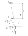
図4は、イメージング装置100による物体OBJの測定を説明する図である。イメージング装置100の奥行き方向の測定範囲は、仕様としてLMIN~LMAXに制限されるものとする。
センシング距離の上限LMAXに位置する物体OBJ2へのラウンドトリップ時間(最大ラウンドトリップ時間)TMAXは、TMAX=2×LMAX/cである。センシング距離の下限LMINに位置する物体OBJ1へのラウンドトリップ時間(最小ラウンドトリップ時間)TMINは、TMIN=2×LMIN/cである。
一例としてLMIN=1.5m、LMAX=60mとすると、最小ラウンドトリップ時間TMINは、2×1.5/(3×108)=10ns、最大ラウンドトリップ時間TMAXは、2×60/(3×108)=400nsとなる。インターバル期間TINTの長さは、最大ラウンドトリップ時間TMAXと等しいか、それより長く定められる。
図5は、イメージング装置100の動作を説明するタイムチャートである。時刻t1~t2の間、ランダムパターンPTN1が照射される。時刻t1に照明装置110を出発した参照光S1は、手前の物体OBJ1で反射し、時刻t1からTMIN経過後の時刻t3に反射光S2_1として光検出器120に戻ってくる。時刻t1に照明装置110を出発した参照光S1は、奥側の物体OBJ2で反射し、時刻t1からTMAX経過後の時刻t4に反射光S2_2として光検出器120に戻ってくる。
時刻t2に照明装置110を出発した参照光S1は、手前の物体OBJ1で反射し、時刻t2からTMIN経過後の時刻t5に反射光S2_1として光検出器120に戻ってくる。時刻t2に照明装置110を出発した参照光S1は、奥側の物体OBJ2で反射し、時刻t2からTMAX経過後の時刻t6に反射光S2_2として光検出器120に戻ってくる。
そして、時刻t2からインターバル期間TINTの経過後の時刻t7に、次のランダムパターンPTN2の照射がスタートする。
たとえばTINTはTMAXより長く設定することができる。上限は特になく、インターバル期間TINTを長くとればとるほど、測定範囲外の物体の反射光の影響を低減することができるが、インターバル期間TINTが長すぎると、照射時間TILMが短くなるか、フレームレートが低下する。たとえば、TMAX=400nsのとき、TINT=0.5msとしてもよい。ランダムパターンの切り替え周波数を400Hzとする場合、TILM=2.5ms-0.5ms=2msとなる。
TINT>TMAXの関係が成り立つとき、物体OBJ2の反射光S2_2は、時刻t7より前に、光検出器120に戻ってくる。したがって、期間t1~t7の間に検出期間TDET1を設定すれば、同じランダムパターンPTN1のみにもとづく反射光S2_1、S2_2が検出される。言い換えれば、時間的に隣接するランダムパターンの干渉を取り除くことができ、画質を改善することができる。
なお、各検出サイクルにおける検出期間TDETの始点は、t1~t3の間に設定すればよく、検出期間TDETの終点は、t6~t7の間に設定すればよい。
厳密に言えば、インターバル期間TINTの長さは、TMAX-TMINより長ければよい。
続いて、イメージング装置100によるセンシングの変形例を説明する。
(変形例1)
検出期間TDETの始点を、物体OBJまでの距離に応じて動的に決定してもよい。具体的には、イメージング装置100から最も近い物体OBJからの反射光が光検出器120に到達した時刻を検出期間TDETの始点としてもよい。
検出期間TDETの始点を、物体OBJまでの距離に応じて動的に決定してもよい。具体的には、イメージング装置100から最も近い物体OBJからの反射光が光検出器120に到達した時刻を検出期間TDETの始点としてもよい。
図6は、変形例1に係るイメージング装置100の動作を説明するタイムチャートである。インターバル期間TINTにおいて参照光S1は完全にオフするものとする。そうすると、インターバル期間TINTの間、照明装置110には反射光S2は入射せず、環境光(外乱ノイズ)のみが入射する。つまり、インターバル期間TINTにおける検出信号Dはランダムパターンの反射光S2が入射する期間に比べて小さいと言える。言い換えれば、検出信号Dがある時刻において急激に上昇したことは、物体OBJからの反射光S2が光検出器120に入射したことと示す。
そこで、演算処理装置130は、光検出器120の出力信号Dを監視し、ノイズレベルから有意な信号レベルまで増大したタイミングを、検出期間TDETの始点に設定する。たとえば演算処理装置130は、ノイズレベルと有意な信号レベルの間にしきい値THを設定し、D>THとなると、検出期間TDETを開始してもよい。
また、演算処理装置130は、光検出器120の出力信号Dを監視し、有意な信号レベルからノイズレベルまで低下するしたタイミングを、検出期間TDETの終点に設定してもよい。たとえば演算処理装置130は、D<THとなると、検出期間TDETを終了してもよい。
たとえば演算処理装置130は、このように設定した検出期間TDETrの間、検出信号Dをサンプリングして取り込み、複数のサンプリング値にもとづいて検出強度brを生成する。
ここで演算処理装置130は、しきい値THを動的に変化させてもよい。たとえば、インターバル期間TINTの間に、ノイズをセンシングするためのノイズ検出期間TNSを設け、ノイズ検出期間TNSにおいて測定された検出信号Dを、ノイズレベルとし、このノイズレベルにもとづいて、次の検出期間TDETのためのしきい値THを設定してもよい。たとえばノイズレベルを所定幅、オフセットしてしきい値THとしてもよいし、ノイズレベルを所定数倍してしきい値THとしてもよい。
変形例1によれば、余計な光の取り込みを低減し、ひいてはノイズ等の影響を低減できる。
(変形例2)
図7は、変形例2に係るイメージング装置100の動作を説明するタイムチャートである。変形例2においても、インターバル期間TINTにおける参照光S1の強度はゼロである。反射光S2が戻ってこない期間(非検出期間という)の間にノイズ検出期間TNSを設け、検出信号Dのノイズレベルを測定し、測定されたノイズレベルにもとづいて、検出信号Dひいては検出強度bを補正する。変形例1の技術を用いて検出期間TDETを設定し、それ以外を非検出期間としてもよい。
図7は、変形例2に係るイメージング装置100の動作を説明するタイムチャートである。変形例2においても、インターバル期間TINTにおける参照光S1の強度はゼロである。反射光S2が戻ってこない期間(非検出期間という)の間にノイズ検出期間TNSを設け、検出信号Dのノイズレベルを測定し、測定されたノイズレベルにもとづいて、検出信号Dひいては検出強度bを補正する。変形例1の技術を用いて検出期間TDETを設定し、それ以外を非検出期間としてもよい。
たとえば検出期間TDETにおいてサンプリングされた検出信号Dから、ノイズ検出期間TNSにおいてサンプリングされた検出信号Dの値(すなわちノイズレベル)を減算し、減算後の検出信号Dにもとづいて、検出強度brを生成してもよい。
あるいは、ノイズ検出期間TNSにおいてサンプリングされた検出信号Dの値を積算し、積算値にもとづいてノイズ補正値Nを生成する。また、検出期間TDETにおいてサンプリングされた検出信号Dを積算して、ノイズを含む検出強度brを生成する。そして、ノイズを含む検出強度brから、ノイズ補正値Nを減算することにより、補正後の検出強度brを生成してもよい。ノイズ補正値Nは、検出期間TDETとノイズ検出期間TNSの長さの比率にもとづいてスケーリングされる。
たとえば照射期間TILMとインターバル期間TINTの長さを等しく設定してもよい。この場合、検出期間TDETと非検出期間を同じ長さとすることができる。そして非検出期間をノイズ検出期間TNSとしてもよい。この場合、検出期間TDETとノイズ検出期間TNSが等しくなるため、ノイズ補正値Nのスケーリングは不要となるため処理を簡素化できる。
(用途)
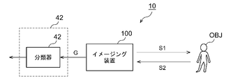
続いてイメージング装置100の用途を説明する。図8は、物体識別システム10のブロック図である。この物体識別システム10は、自動車やバイクなどの車両に搭載され、車両の周囲に存在する物体OBJの種類(カテゴリ)を判定する。
続いてイメージング装置100の用途を説明する。図8は、物体識別システム10のブロック図である。この物体識別システム10は、自動車やバイクなどの車両に搭載され、車両の周囲に存在する物体OBJの種類(カテゴリ)を判定する。
物体識別システム10は、イメージング装置100と、演算処理装置40を備える。イメージング装置100は、上述のように、物体OBJに参照光S1を照射し、反射光S2を測定することにより、物体OBJの復元画像Gを生成する。
演算処理装置40は、イメージング装置100の出力画像Gを処理し、物体OBJの位置および種類(カテゴリ)を判定する。
演算処理装置40の分類器42は、画像Gを入力として受け、それに含まれる物体OBJの位置および種類を判定する。分類器42は、機械学習によって生成されたモデルにもとづいて実装される。分類器42のアルゴリズムは特に限定されないが、YOLO(You Only Look Once)とSSD(Single Shot MultiBox Detector)、R-CNN(Region-based Convolutional Neural Network)、SPPnet(Spatial Pyramid Pooling)、Faster R-CNN、DSSD(Deconvolution -SSD)、Mask R-CNNなどを採用することができ、あるいは、将来開発されるアルゴリズムを採用できる。
以上が物体識別システム10の構成である。物体識別システム10のセンサとして、イメージング装置100を用いることで、以下の利点を得ることができる。
イメージング装置100すなわち量子レーダカメラを用いることで、ノイズ耐性が格段に高まる。たとえば、降雨時、降雪時、あるいは霧の中を走行する場合、肉眼では物体OBJを認識しにくいが、イメージング装置100を用いることで、雨、雪、霧の影響を受けずに、物体OBJの復元画像Gを得ることができる。
また実施の形態に係るイメージング装置100を用いることを特徴とするで、時間的に隣接するランダムパターンの干渉を防止でき、画質を改善できる。
図9は、物体識別システム10を備える自動車のブロック図である。自動車300は、前照灯302L,302Rを備える。イメージング装置100は、前照灯302L,302Rの少なくとも一方に内蔵される。前照灯302は、車体の最も先端に位置しており、周囲の物体を検出する上で、イメージング装置100の設置箇所として最も有利である。
図10は、物体検出システム210を備える車両用灯具200を示すブロック図である。車両用灯具200は、車両側ECU304とともに灯具システム310を構成する。車両用灯具200は、光源202、点灯回路204、光学系206を備える。さらに車両用灯具200には、物体検出システム210が設けられる。物体検出システム210は、上述の物体識別システム10に対応しており、イメージング装置100および演算処理装置40を含む。
演算処理装置40が検出した物体OBJに関する情報は、車両用灯具200の配光制御に利用してもよい。具体的には、灯具側ECU208は、演算処理装置40が生成する物体OBJの種類とその位置に関する情報にもとづいて、適切な配光パターンを生成する。点灯回路204および光学系206は、灯具側ECU208が生成した配光パターンが得られるように動作する。
また演算処理装置40が検出した物体OBJに関する情報は、車両側ECU304に送信してもよい。車両側ECUは、この情報にもとづいて、自動運転を行ってもよい。
以上、本発明について、実施の形態をもとに説明した。この実施の形態は例示であり、それらの各構成要素や各処理プロセスの組み合わせにいろいろな変形例が可能なこと、またそうした変形例も本発明の範囲にあることは当業者に理解されるところである。以下、こうした変形例について説明する。
実施の形態では、照明装置110を、光源112とパターニングデバイス114の組み合わせで構成したがその限りでない。たとえば照明装置110は、マトリクス状に配置される複数の半導体光源(LED(発光ダイオード)やLD(レーザダイオード))のアレイで構成し、個々の半導体光源のオン、オフ(あるいは輝度)を制御可能に構成してもよい。
実施の形態において、ゴーストイメージング(あるいはシングルピクセルイメージング)の手法として、相関計算を用いた手法を説明したが、画像の再構築の手法はそれに限定されない。いくつかの実施の形態では、相関計算に変えて、フーリエ変換やアダマール逆変換を使用した解析的手法や、スパースモデリングなどの最適化問題を解く手法、およびAI・機械学習を利用したアルゴリズムによって、画像を再構築してもよい。
実施の形態にもとづき、具体的な語句を用いて本発明を説明したが、実施の形態は、本発明の原理、応用の一側面を示しているにすぎず、実施の形態には、請求の範囲に規定された本発明の思想を逸脱しない範囲において、多くの変形例や配置の変更が認められる。
本発明は、車載用イメージング装置に関する。
OBJ 物体
10 物体識別システム
40 演算処理装置
42 分類器
100 イメージング装置
110 照明装置
112 光源
114 パターニングデバイス
120 光検出器
130 演算処理装置
132 パターン発生器
134 再構成処理部
200 車両用灯具
202 光源
204 点灯回路
206 光学系
300 自動車
302 前照灯
310 灯具システム
304 車両側ECU
10 物体識別システム
40 演算処理装置
42 分類器
100 イメージング装置
110 照明装置
112 光源
114 パターニングデバイス
120 光検出器
130 演算処理装置
132 パターン発生器
134 再構成処理部
200 車両用灯具
202 光源
204 点灯回路
206 光学系
300 自動車
302 前照灯
310 灯具システム
304 車両側ECU
Claims (9)
- 車載用イメージング装置であって、
照射期間ごとに切り替わるランダムパターンを有する参照光を照射する照明装置と、
物体からの反射光を測定する光検出器と、
前記光検出器の出力にもとづく検出強度と前記参照光の強度分布にもとづいて前記物体の復元画像を再構成する演算処理装置と、
を備え、
前記照射期間と前記照射期間の間に、強度がゼロまたは強度分布が均一であるインターバル期間が挿入され、前記車載用イメージング装置の奥行き方向のセンシング距離の上限をLMAX、光速をcとするとき、前記インターバル期間は2×LMAX/c以上であることを特徴とする車載用イメージング装置。 - 前記演算処理装置は、前記検出強度がしきい値より大きい期間において得られた前記光検出器の出力にもとづいて前記検出強度を生成することを特徴とする請求項1に記載の車載用イメージング装置。
- 前記演算処理装置は、前記検出強度がしきい値を超えると、前記検出強度の取り込みを開始することを特徴とする請求項1に記載の車載用イメージング装置。
- 前記演算処理装置は、前記検出強度がしきい値を下回ると、前記検出強度の取り込みを終了することを特徴とする請求項1または3に記載の車載用イメージング装置。
- 前記しきい値は、前記インターバル期間において得られた前記検出強度にもとづいて設定されることを特徴とする請求項2から4のいずれかに記載の車載用イメージング装置。
- 前記インターバル期間における前記参照光の強度はゼロであり、
前記演算処理装置は、前記インターバル期間において得られた前記検出強度を用いて、前記復元画像の再構成に用いる前記検出強度を補正することを特徴とする請求項1から5のいずれかに記載の車載用イメージング装置。 - 前記照射期間と前記インターバル期間の長さは等しいことを特徴とする請求項6に記載の車載用イメージング装置。
- 請求項1から7のいずれかに記載の車載用イメージング装置を備えることを特徴とする車両用灯具。
- 請求項1から7のいずれかに記載の車載用イメージング装置を備えることを特徴とする自動車。
Priority Applications (3)
| Application Number | Priority Date | Filing Date | Title |
|---|---|---|---|
| JP2020566186A JP7463297B2 (ja) | 2019-01-17 | 2019-12-26 | 車載用イメージング装置、車両用灯具、自動車 |
| CN201980089167.0A CN113366340B (zh) | 2019-01-17 | 2019-12-26 | 车载用成像装置、车辆用灯具、汽车 |
| US17/377,456 US12392901B2 (en) | 2019-01-17 | 2021-07-16 | In-vehicle imaging apparatus |
Applications Claiming Priority (2)
| Application Number | Priority Date | Filing Date | Title |
|---|---|---|---|
| JP2019-006086 | 2019-01-17 | ||
| JP2019006086 | 2019-01-17 |
Related Child Applications (1)
| Application Number | Title | Priority Date | Filing Date |
|---|---|---|---|
| US17/377,456 Continuation US12392901B2 (en) | 2019-01-17 | 2021-07-16 | In-vehicle imaging apparatus |
Publications (1)
| Publication Number | Publication Date |
|---|---|
| WO2020149140A1 true WO2020149140A1 (ja) | 2020-07-23 |
Family
ID=71614393
Family Applications (1)
| Application Number | Title | Priority Date | Filing Date |
|---|---|---|---|
| PCT/JP2019/051193 Ceased WO2020149140A1 (ja) | 2019-01-17 | 2019-12-26 | 車載用イメージング装置、車両用灯具、自動車 |
Country Status (4)
| Country | Link |
|---|---|
| US (1) | US12392901B2 (ja) |
| JP (1) | JP7463297B2 (ja) |
| CN (1) | CN113366340B (ja) |
| WO (1) | WO2020149140A1 (ja) |
Cited By (4)
| Publication number | Priority date | Publication date | Assignee | Title |
|---|---|---|---|---|
| WO2022091972A1 (ja) * | 2020-10-28 | 2022-05-05 | 株式会社小糸製作所 | イメージング装置および車両用灯具、車両 |
| WO2022102775A1 (ja) * | 2020-11-16 | 2022-05-19 | 株式会社小糸製作所 | センシング装置、車両用灯具、車両 |
| JPWO2022153969A1 (ja) * | 2021-01-12 | 2022-07-21 | ||
| WO2023176636A1 (ja) * | 2022-03-16 | 2023-09-21 | パナソニックIpマネジメント株式会社 | 撮像装置 |
Families Citing this family (2)
| Publication number | Priority date | Publication date | Assignee | Title |
|---|---|---|---|---|
| WO2021193646A1 (ja) * | 2020-03-26 | 2021-09-30 | 株式会社小糸製作所 | イメージング装置および車両用灯具、車両 |
| KR102369817B1 (ko) * | 2021-08-18 | 2022-03-04 | 국방과학연구소 | 압축된 양자 조명 광원을 생성하는 방법 및 이를 이용한 양자 레이더 장치 |
Citations (8)
| Publication number | Priority date | Publication date | Assignee | Title |
|---|---|---|---|---|
| JPH0112673B2 (ja) * | 1983-06-01 | 1989-03-01 | Sumitomo Beekuraito Kk | |
| JP2012037267A (ja) * | 2010-08-04 | 2012-02-23 | Hitachi High-Technologies Corp | 光量検出方法及びその装置 |
| JP2013096905A (ja) * | 2011-11-02 | 2013-05-20 | Denso Corp | 測距装置 |
| WO2016208215A1 (ja) * | 2015-06-24 | 2016-12-29 | 株式会社村田製作所 | 距離センサ及びユーザインタフェース装置 |
| WO2017110417A1 (ja) * | 2015-12-21 | 2017-06-29 | 株式会社小糸製作所 | 車両用画像取得装置、制御装置、車両用画像取得装置または制御装置を備えた車両および車両用画像取得方法 |
| JP2017525952A (ja) * | 2014-07-31 | 2017-09-07 | レイセオン カンパニー | 線形モード計算センシングレーザーレーダー |
| CN108363069A (zh) * | 2018-01-18 | 2018-08-03 | 中国科学院理化技术研究所 | 基于分布式半导体激光阵列的关联成像装置及方法 |
| JP2018156862A (ja) * | 2017-03-17 | 2018-10-04 | トヨタ自動車株式会社 | 車両用前照灯装置 |
Family Cites Families (8)
| Publication number | Priority date | Publication date | Assignee | Title |
|---|---|---|---|---|
| JP5681675B2 (ja) * | 2011-07-29 | 2015-03-11 | 富士フイルム株式会社 | 光音響画像生成装置及び音響波ユニット |
| WO2015075926A1 (ja) | 2013-11-20 | 2015-05-28 | パナソニックIpマネジメント株式会社 | 測距撮像システム |
| JP2017133853A (ja) * | 2016-01-25 | 2017-08-03 | 株式会社リコー | 測距装置 |
| JPWO2017187484A1 (ja) * | 2016-04-25 | 2018-12-20 | 株式会社日立製作所 | 物体撮像装置 |
| WO2019016968A1 (ja) | 2017-07-21 | 2019-01-24 | 学校法人玉川学園 | 画像処理装置及び方法、並びに、プログラム |
| WO2019016994A1 (ja) * | 2017-07-21 | 2019-01-24 | 学校法人玉川学園 | 画像処理装置及び方法、並びに、プログラム |
| JP6412673B1 (ja) * | 2017-07-21 | 2018-10-24 | 学校法人玉川学園 | 画像処理装置及び方法、並びに、プログラム |
| EP3998767B1 (en) * | 2019-07-12 | 2023-10-11 | Koito Manufacturing Co., Ltd. | Imaging device, lighting device for same, vehicle, and lamp fitting for vehicle |
-
2019
- 2019-12-26 WO PCT/JP2019/051193 patent/WO2020149140A1/ja not_active Ceased
- 2019-12-26 CN CN201980089167.0A patent/CN113366340B/zh active Active
- 2019-12-26 JP JP2020566186A patent/JP7463297B2/ja active Active
-
2021
- 2021-07-16 US US17/377,456 patent/US12392901B2/en active Active
Patent Citations (8)
| Publication number | Priority date | Publication date | Assignee | Title |
|---|---|---|---|---|
| JPH0112673B2 (ja) * | 1983-06-01 | 1989-03-01 | Sumitomo Beekuraito Kk | |
| JP2012037267A (ja) * | 2010-08-04 | 2012-02-23 | Hitachi High-Technologies Corp | 光量検出方法及びその装置 |
| JP2013096905A (ja) * | 2011-11-02 | 2013-05-20 | Denso Corp | 測距装置 |
| JP2017525952A (ja) * | 2014-07-31 | 2017-09-07 | レイセオン カンパニー | 線形モード計算センシングレーザーレーダー |
| WO2016208215A1 (ja) * | 2015-06-24 | 2016-12-29 | 株式会社村田製作所 | 距離センサ及びユーザインタフェース装置 |
| WO2017110417A1 (ja) * | 2015-12-21 | 2017-06-29 | 株式会社小糸製作所 | 車両用画像取得装置、制御装置、車両用画像取得装置または制御装置を備えた車両および車両用画像取得方法 |
| JP2018156862A (ja) * | 2017-03-17 | 2018-10-04 | トヨタ自動車株式会社 | 車両用前照灯装置 |
| CN108363069A (zh) * | 2018-01-18 | 2018-08-03 | 中国科学院理化技术研究所 | 基于分布式半导体激光阵列的关联成像装置及方法 |
Cited By (7)
| Publication number | Priority date | Publication date | Assignee | Title |
|---|---|---|---|---|
| WO2022091972A1 (ja) * | 2020-10-28 | 2022-05-05 | 株式会社小糸製作所 | イメージング装置および車両用灯具、車両 |
| WO2022102775A1 (ja) * | 2020-11-16 | 2022-05-19 | 株式会社小糸製作所 | センシング装置、車両用灯具、車両 |
| JPWO2022153969A1 (ja) * | 2021-01-12 | 2022-07-21 | ||
| WO2022153969A1 (ja) * | 2021-01-12 | 2022-07-21 | 富士フイルム株式会社 | イメージング方法、及びイメージング装置 |
| US12289540B2 (en) | 2021-01-12 | 2025-04-29 | Fujifilm Corporation | Imaging method and imaging device calculating the correlation between light intensity and a spatially modulated mask image to construct an image of a target object |
| JP7742364B2 (ja) | 2021-01-12 | 2025-09-19 | 富士フイルム株式会社 | イメージング方法、及びイメージング装置 |
| WO2023176636A1 (ja) * | 2022-03-16 | 2023-09-21 | パナソニックIpマネジメント株式会社 | 撮像装置 |
Also Published As
| Publication number | Publication date |
|---|---|
| JPWO2020149140A1 (ja) | 2021-12-02 |
| US20210341618A1 (en) | 2021-11-04 |
| JP7463297B2 (ja) | 2024-04-08 |
| US12392901B2 (en) | 2025-08-19 |
| CN113366340B (zh) | 2024-10-18 |
| CN113366340A (zh) | 2021-09-07 |
Similar Documents
| Publication | Publication Date | Title |
|---|---|---|
| JP7463297B2 (ja) | 車載用イメージング装置、車両用灯具、自動車 | |
| US12047667B2 (en) | Imaging device | |
| US12003839B2 (en) | Imaging apparatus using ghost imaging | |
| US12108164B2 (en) | Imaging apparatus | |
| WO2022270476A1 (ja) | イメージング装置および車両用灯具、車両 | |
| CN111398975A (zh) | 主动传感器、物体识别系统、车辆、车辆用灯具 | |
| JP7395511B2 (ja) | イメージング装置、その演算処理装置、車両用灯具、車両、センシング方法 | |
| JP7524207B2 (ja) | イメージング装置、車両用灯具、車両、イメージング方法 | |
| WO2023085328A1 (ja) | イメージング装置およびイメージング方法、車両用灯具、車両 | |
| JP7631849B2 (ja) | 3次元計測装置、3次元計測方法、3次元計測プログラム | |
| WO2021079810A1 (ja) | イメージング装置、車両用灯具、車両、イメージング方法 | |
| WO2022091972A1 (ja) | イメージング装置および車両用灯具、車両 | |
| US12205335B2 (en) | Imaging apparatus and imaging method | |
| WO2023085329A1 (ja) | イメージングシステム、センサユニット、車両用灯具、車両 | |
| CN117795377A (zh) | 门控照相机、车辆用传感系统、车辆用灯具 | |
| WO2022102775A1 (ja) | センシング装置、車両用灯具、車両 | |
| WO2023074759A1 (ja) | イメージング装置、車両用灯具、車両 | |
| CN116457700A (zh) | 感测装置、车辆用灯具、车辆 | |
| CN118215854A (zh) | 感测系统及汽车 |
Legal Events
| Date | Code | Title | Description |
|---|---|---|---|
| 121 | Ep: the epo has been informed by wipo that ep was designated in this application |
Ref document number: 19910135 Country of ref document: EP Kind code of ref document: A1 |
|
| ENP | Entry into the national phase |
Ref document number: 2020566186 Country of ref document: JP Kind code of ref document: A |
|
| NENP | Non-entry into the national phase |
Ref country code: DE |
|
| 122 | Ep: pct application non-entry in european phase |
Ref document number: 19910135 Country of ref document: EP Kind code of ref document: A1 |