WO2020149130A1 - 航空機用投影装置 - Google Patents
航空機用投影装置 Download PDFInfo
- Publication number
- WO2020149130A1 WO2020149130A1 PCT/JP2019/050964 JP2019050964W WO2020149130A1 WO 2020149130 A1 WO2020149130 A1 WO 2020149130A1 JP 2019050964 W JP2019050964 W JP 2019050964W WO 2020149130 A1 WO2020149130 A1 WO 2020149130A1
- Authority
- WO
- WIPO (PCT)
- Prior art keywords
- aircraft
- projection
- image
- unit
- projection device
- Prior art date
- Legal status (The legal status is an assumption and is not a legal conclusion. Google has not performed a legal analysis and makes no representation as to the accuracy of the status listed.)
- Ceased
Links
Images





Classifications
-
- B—PERFORMING OPERATIONS; TRANSPORTING
- B64—AIRCRAFT; AVIATION; COSMONAUTICS
- B64D—EQUIPMENT FOR FITTING IN OR TO AIRCRAFT; FLIGHT SUITS; PARACHUTES; ARRANGEMENT OR MOUNTING OF POWER PLANTS OR PROPULSION TRANSMISSIONS IN AIRCRAFT
- B64D47/00—Equipment not otherwise provided for
- B64D47/02—Arrangements or adaptations of signal or lighting devices
-
- G—PHYSICS
- G08—SIGNALLING
- G08G—TRAFFIC CONTROL SYSTEMS
- G08G5/00—Traffic control systems for aircraft
- G08G5/80—Anti-collision systems
Definitions
- the present invention relates to the technical field of an aircraft projection device that displays an image by projecting it.
- the aircraft is equipped with various types of lighting depending on the intended use.
- external lighting anti-collision lights that prevent collisions between aircraft
- aircraft lights that indicate the flight attitude and flight direction of the aircraft, gliding during takeoff and landing.
- landing lights that illuminate roads, logo lights that illuminate the logo printed on the fuselage, and the like (see, for example, Patent Documents 1 and 2).
- Such external lighting ensures a safe flight condition of the aircraft and a safe driving condition on the runway during takeoff and landing.
- the purpose of the present invention aircraft projection device is to improve convenience for pilots and ground workers.
- An aircraft projection apparatus is an aircraft projection apparatus used in a state of being attached to a body of an aircraft and landing, and a projection unit for displaying an image by projecting an image on a road surface outside the aircraft. And a control unit that controls the projection unit to display an image.
- the projection light be emitted directly below from the projection unit.
- the projection unit be attached to the inner surface of the storage cover that opens and closes the front legs that are put in and taken out from the fuselage of the aircraft.
- the projection unit displays the traveling direction of the aircraft as an image.
- the flight direction of the aircraft is displayed on the road surface during takeoff and landing, so that the pilot or ground worker can visually recognize the flight direction of the aircraft.
- the projection unit displays a caution mark as an image.
- the present invention it becomes possible for a pilot or a ground worker to recognize an item provided to the pilot or a ground worker by visually recognizing an image displayed on the road surface outside the aircraft,
- the convenience for the ground workers can be improved.
- FIG. 7 is a diagram showing an operation example of the aircraft projection device together with FIG. 7 and FIG. 8, and this figure is a diagram showing a state where the aircraft is on standby in the standby area. It is a figure showing the state where the airplane is running toward the runway. It is a figure which shows the state which the aircraft has run to the runway and is on standby. It is a figure which shows the example of the drawing content of an image.
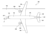
- the body 101 of the aircraft 100 has a body 102 and various wings (see FIGS. 1 to 3).
- a window 103 for viewing the outside from the cockpit is attached to the front end of the body 102.
- Storage covers 104, 104 are provided at the lower end of the front end of the body 102 so as to be openable and closable (see FIGS. 1 and 3). When the storage covers 104, 104 are opened, the front legs 200 are projected from the inside of the body 102, and when the front legs 200 are stored inside the body 102, the storage covers 104, 104 are closed and the front legs 200 are stored. Protected by the covers 104, 104.
- the front end of the body 102 is provided as a radome 105.
- the front leg 200 has a front wheel 201 for traveling and a column 202 that supports the front wheel 201.
- main wings 300, 300, vertical tails 301, and horizontal tails 302, 302 are provided (see FIGS. 1 to 3).
- a rear not-shown storage cover is provided at the left and right main wings 300 or a position extending from the main wing 300 to the fuselage 102 so that the rear cover can be opened and closed. It is projected from the inside or stored inside the body 102.
- Jet engines 600 are attached to the left and right main wings 300 via pylons 500, respectively.
- the aircraft projection device 1 is attached to the inner surface 104a of the storage cover 104 (see FIG. 3). However, at least the projection unit of the aircraft projection device 1 described below may be attached to the storage cover 104.
- the aircraft projection devices 1 and 1 may be attached to the inner surfaces 104a and 104a of the left and right storage covers 104 and 104, respectively.
- the aircraft projection device 1 or the projection unit is not limited to the storage cover 104, and may be attached to any position of the airframe 101 as long as the image can be projected on the road surface 700 outside the aircraft 100. May be.
- the aircraft projection device 1 By mounting the aircraft projection device 1 on the inner surface 104a of the storage cover 104, the aircraft projection device 1 is exposed when the aircraft 100 is landing, and the aircraft projection device 1 is inside the fuselage 102 during flight of the aircraft 100. And the aircraft projection device 1 is protected.
- the aircraft projection device 1 may be attached to the column 202 of the front leg 200, and in this case, as in the case where the aircraft projection device 1 is attached to the inner surface 104 a of the storage cover 104, When the aircraft 100 lands, the aircraft projection device 1 is exposed, and during the flight of the aircraft 100, the aircraft projection device 1 is stored inside the fuselage 102 to protect the aircraft projection device 1.
- the aircraft projection device 1 when the aircraft projection device 1 is attached to the support column 202, an impact is likely to be applied to the aircraft projection device 1 via the front wheels 201 when the aircraft 100 lands on the runway. More preferably, the aircraft projection device 1 is attached to the small number of storage covers 104.
- the aircraft projection device 1 projects the image P onto the road surface 700, and the image P is displayed (see FIG. 2).
- the image P for example, the traveling direction of the aircraft 100 is displayed.
- the image P is displayed, for example, in front of or obliquely in front of the aircraft 100, and is visible to the pilot or co-pilot seated in the cockpit seat. Therefore, the pilot or co-pilot recognizes the direction of travel toward the runway during takeoff. Further, by displaying the traveling direction as the image P, it is possible to achieve communication with a ground guide (marshaller) who guides the traveling of the aircraft 100.
- a ground guide (marshaller) who guides the traveling of the aircraft 100.
- the position where the image P is displayed may be a side of the aircraft 100, a diagonally rear, or the like, and is preferably a position visible to the pilot or copilot seated in the cockpit seat.
- the preparatory work for takeoff is being performed on the aircraft 100 or the state immediately before takeoff.
- the ground work is performed.
- Various work is performed by the staff. For example, at this time, a ground worker performs a work of loading luggage into the luggage compartment of the aircraft 100, an inspection work of each part of the aircraft 100, a refueling work of the aircraft 100, a cleaning work of the aircraft 100, and the like.
- the traveling direction of the aircraft 100 is recognized.
- the image P is displayed on the road surface 700 while the image P showing the correct traveling direction is being switched while the aircraft 100 is traveling toward the runway after the traveling starts.
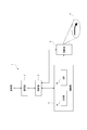
- the aircraft projection device 1 has a control unit 2, a drawing unit 3, a projection unit 4, and a communication unit 5.
- the control unit 2 includes, for example, a microcomputer including a CPU (Central Processing Unit), a RAM (Random Access Memory), a ROM (Read Only Memory), an EEPROM (ElectricallyErasable Programmable Read Only Memory), and the communication unit 5
- a microcomputer including a CPU (Central Processing Unit), a RAM (Random Access Memory), a ROM (Read Only Memory), an EEPROM (ElectricallyErasable Programmable Read Only Memory), and the communication unit 5
- the operation of the drawing unit 3 and the projection unit 4 is controlled based on the information input from.
- the drawing unit 3 performs a process of generating the content of the image of the image P, and includes, for example, a CG-ROM (Character Generator Rom) 3a and a VDP (Video Display Processor) 3b.
- CG-ROM Charger Generator Rom
- VDP Video Display Processor
- the VDP 3b draws the image P using the material image read from the CG-ROM 3a, and supplies the drawing data to the projection unit 4.
- the drawing unit 3 draws the necessary content at a necessary timing in response to an instruction from the control unit 2, for example.
- the projection unit 4 has, for example, a light source unit, a light modulation unit, a projection lens system, and the like, and projects the image P based on the drawing data transferred from the drawing unit 3 to display the image P on the road surface 700.
- the light source unit various light sources such as an LED (Light Emitting Diode), a laser light source, a xenon lamp, and a mercury lamp are used.
- the light modulator for example, a liquid crystal light valve is used.
- the image P drawn by the drawing unit 3 is displayed on the road surface 700 by controlling the liquid crystal light valve according to the drawing data and modulating the projection light by the light modulator.
- the communication unit 5 communicates with the control tower located at the airport or at a position other than the airport.
- the communication unit 5 receives, for example, a command from the control tower, and transmits a command to start projection and a command to end projection to the projection device 1 for aircraft to the control unit 2.
- the control tower monitors the current state of the aircraft 100 from time to time, grasps and determines the progress status of various operations on the aircraft 100 before takeoff, inspection results in inspection work, runway usage status, takeoff time, etc.
- the command is transmitted to the communication unit 5 based on these pieces of information.
- control unit 2 performs, for example, the following control (see FIG. 5).
- the control unit 2 performs processing at predetermined timings, and repeatedly executes the following processing.
- step S10 the control unit 2 confirms the reception of a command from the control tower via the communication unit 5 by a command check.
- step S11 the control unit 2 determines the presence/absence of a projection start trigger based on the command check in step S10.
- the projection start trigger is a predetermined condition for starting the display of the image P, and is generated, for example, when the projection start condition is met in the state where the communication unit 5 receives the projection start command.
- the determination condition of the projection start trigger may be set according to the usage mode of the aircraft projection device 1.
- the projection start trigger is, for example, a command matching the material image stored in the CG-ROM 3a in the command check in step 10, and reaches the timing of displaying the image P calculated from the estimated takeoff time and the like. It occurs because it is the time when
- control unit 2 proceeds from step S11 to step S12, and instructs drawing for projection of the image P according to the determined projection start trigger. That is, the control unit 2 instructs the drawing unit 3 to execute drawing and the content of the image P.
- step S13 the control unit 2 instructs the projection unit 4 to start projection. Thereby, the projection based on the drawing data generated by the drawing unit 3 is started by the projection unit 4, and the predetermined image P is displayed on the road surface 700.
- the control unit 2 determines in step S14 whether the projection is in progress and the projection end trigger has occurred.
- the projection end trigger is a predetermined condition for ending the display of the image P, and is generated, for example, when the communication unit 5 receives a projection end command.
- the determination condition of the projection end trigger may be set in correspondence with the projection start trigger.
- control unit 2 determines in step S14 based on the command check in the immediately preceding step S10 whether or not a projection end trigger has occurred.
- control unit 2 proceeds from step S14 to step S15 and instructs the projection unit 4 to end the projection.
- the projection by the projection unit 4 based on the drawing data generated by the drawing unit 3 is completed.
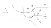
- the aircraft projection start trigger When it is determined that the projection start trigger is generated while various operations are being performed on the aircraft 100 before takeoff in a state where the aircraft 100 is waiting in the waiting area 800 such as a passenger landing, the aircraft projection An image P indicating the traveling direction of the aircraft 100 is projected on the road surface 700 by the device 1 (see FIG. 6). At this time, various operations such as load-in work, inspection work, refueling work, and cleaning work are performed by the ground workers.
- the aircraft 100 starts running toward the runway 900 before takeoff.
- the image P indicating the correct traveling direction is displayed on the road surface 700 while being switched (see FIG. 7). Therefore, the pilot or the co-pilot can visually confirm the image P and confirm whether or not the aircraft 100 is traveling in the correct traveling direction.
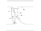
- the aircraft 100 When the aircraft 100 that has traveled toward the runway 900 reaches the start line 901 of the runway 900, the aircraft 100 is temporarily stopped and waits until a run enable command for the runway 900 is issued from the control tower (FIG. 8). reference). At this time, the occurrence of the projection end trigger is determined, and the projection of the image P ends. Therefore, the display of the image P on the road surface 700 is terminated.
- the image P showing the correct traveling direction is displayed on the road surface 700 while being switched, so that the pilot or the co-pilot can be surely obtained. Become a guide.
- the image P indicating the correct traveling direction may be displayed.
- the traveling direction As the image P, it is possible to achieve communication with a ground guide (marshaller) who guides the traveling of the aircraft 100.
- a caution mark for the ground workers may be displayed (see FIG. 9).
- a display for example, an image P1 showing a scheduled takeoff time, an image P2 showing a destination, and the like are assumed.
- the image P1 showing the estimated take-off time and the time until departure it becomes possible for the ground worker to confirm the time when the work should be finished, and by displaying the destination image P2, the ground worker's luggage It is possible to prevent an error in the delivery destination.
- the image P indicates, for example, a welcome image P3 indicating that the passenger is currently on board, an image P4 indicating a departure time delay with respect to the scheduled time, an image indicating that the passenger is currently preparing to board, and an emergency state. It may be an image, an image showing the logo of an airline, or the like. Further, each of these images P may be displayed in a different color or may be displayed in a blinking manner depending on the intended use.
- At least the projection unit 4 of the aircraft projection device 1 in which the projection unit 4 is moved in and out of the body 102 is the front leg 200. Is attached to the inner surface 104a of the storage cover 104 that opens and closes.
- the projection unit 4 in a state in which the storage cover 104 is opened, so that the projection unit 4 can be protected during flight and a dedicated placement unit for placing the projection unit 4 can be provided.
- the manufacturing cost can be reduced without the need.
- the projection unit 4 displays the traveling direction of the aircraft 100 as the image P
- the traveling direction of the aircraft 100 is displayed on the road surface 700 at the time of takeoff and landing. Therefore, the pilot visually recognizes the traveling direction of the aircraft 100. Therefore, the aircraft 100 can smoothly travel on the correct travel route during takeoff and landing.
- the projection unit 4 displays the traveling direction of the aircraft 100 as the image P
- the traveling direction of the aircraft 100 is displayed on the road surface 700 at the time of takeoff and landing, so that the ground worker visually recognizes the traveling direction of the aircraft 100. Then, at the time of takeoff and landing, the ground worker can stand by at the position retracted from the traveling route of the aircraft 100, and the safety can be improved.
- the projection unit 4 displays the attention mark as the image P
- the attention mark is displayed on the road surface 700 at the time of takeoff and landing, so that the ground worker can visually recognize that the attention state is set. It becomes possible and the safety at the time of takeoff and landing can be improved.
- the image P functions as a clear and easily recognizable display by being displayed on the road surface 700 at night, but the display of the image P is not limited to the night and may be displayed during the daytime. .. Further, the image P is not limited to characters and may be a figure, a mark, or the like.
- the projection device 1 for an aircraft is used in a state where it is attached to the airframe 101 of the aircraft 100 and landed, and is displayed by projecting the image P on the road surface 700 outside the aircraft 100.
- the control unit 2 includes a unit 4 and a control unit 2 that controls the projection unit 4 to display the image P.
- the pilot or the ground worker it becomes possible for the pilot or the ground worker to recognize the provisions to the pilot or the ground worker by visually recognizing the image P displayed on the road surface 700 outside the aircraft 100, and the pilot or the ground worker can be recognized. It is possible to improve convenience for workers.
- the projection light is emitted from directly below the projection unit 4 and the image P is displayed immediately below the projection unit 4.
- the distance from the projection unit 4 to each display portion in the image P does not significantly differ. It is difficult for the image P displayed on the road surface 700 to have a distorted shape such as characters or the like, and a clear image P can be displayed on the road surface 700.
- the aircraft projection device 1 may be provided with a sensor unit such as a speed sensor, and the projection start trigger or the projection end trigger may be generated based on the detection information from the sensor unit.
- a sensor unit such as a speed sensor
- the projection start trigger or the projection end trigger may be generated based on the detection information from the sensor unit.
- the traveling speed of the aircraft is detected by the speed sensor
- a projection start trigger is generated when the traveling speed is detected to be less than a certain value
- the traveling speed is detected to be a certain value or more. It is possible to configure so that an end projection trigger sometimes occurs.
- Aircraft projection device 2... Control unit, 4... Projection unit, 100... Aircraft, 101... Airframe, 104... Storage cover, 700... Road surface
Landscapes
- Engineering & Computer Science (AREA)
- Aviation & Aerospace Engineering (AREA)
- Physics & Mathematics (AREA)
- General Physics & Mathematics (AREA)
- Lighting Device Outwards From Vehicle And Optical Signal (AREA)
- Road Signs Or Road Markings (AREA)
- Illuminated Signs And Luminous Advertising (AREA)
- Projection Apparatus (AREA)
- Radar, Positioning & Navigation (AREA)
- Remote Sensing (AREA)
Abstract
航空機100の機体101に取り付けられ着陸した状態において使用され、航空機の機外における路面700に画像Pを投影することにより表示させる投影部4と、投影部に画像の表示を実行させるように制御を行う制御部2とを備えた。これにより、航空機の機外における路面に表示された画像を操縦士や地上作業員が視認することにより操縦士や地上作業員に対する提供事項を認識することが可能になり、操縦士や地上作業員に対する利便性の向上を図ることができる。
Description
本発明は画像を投影することにより表示させる航空機用投影装置についての技術分野に関する。
航空機には、使用用途に応じて各種の灯具が設けられており、例えば、外部照明として、航空機同士の衝突を防止する衝突防止灯、機体の飛行姿勢や飛行方向を示す航空灯、離着陸時に滑走路を照射する着陸灯、機体に記されたロゴを照明するロゴ灯等が存在する(例えば、特許文献1及び特許文献2参照)。
このような外部照明によって航空機の安全な飛行状態及び離着陸時の滑走路等での安全な走行状態が確保される。
ところで、空港には多くの航空機が離着陸する一方、滑走路の数は限られており、滑走路での円滑かつ安全な走行状態を確保する必要がある。また、着陸後や離陸前には地上作業員による給油作業や各部の点検作業等の多くの作業が必要である。従って、安全な走行や安全かつ迅速な作業を図るために、操縦士や地上作業員の利便性の向上が図られることが望ましい。
そこで、本発明航空機用投影装置は、操縦士や地上作業員に対する利便性の向上を図ることを目的とする。
本発明に係る航空機用投影装置は、航空機の機体に取り付けられ着陸した状態において使用される航空機用投影装置であって、前記航空機の機外における路面に画像を投影することにより表示させる投影部と、前記投影部に画像の表示を実行させるように制御を行う制御部とを備えたものである。
これにより、航空機の機外における路面に表示された画像を操縦士や地上作業員が視認することにより操縦士や地上作業員に対する提供事項を認識することが可能になる。
第2に、上記した本発明に係る航空機用投影装置においては、前記投影部から真下に投影光が出射されることが望ましい。
これにより、投影部から画像における各表示部分までの距離が大きく異なることがないため、路面に表示される画像の形状や文字等が歪んだ形状になり難い。
第3に、上記した本発明に係る航空機用投影装置においては、前記投影部が前記航空機の胴体に対して出し入れされる前脚を開閉する格納カバーの内面に取り付けられることが望ましい。
これにより、格納カバーが開放された状態において投影部を使用することが可能になる。
第4に、上記した本発明に係る航空機用投影装置においては、前記投影部が画像として前記航空機の進行方向を表示することが望ましい。
これにより、離着陸時において路面に航空機の進行方向が表示されるため、操縦士や地上作業員が航空機の進行方向を目視により認識することが可能になる。
第5に、上記した本発明に係る航空機用投影装置においては、前記投影部が画像として注意喚起マークを表示することが望ましい。
これにより、地上作業員が注意喚起状態であることを目視により認識することが可能になる。
本発明によれば、航空機の機外における路面に表示された画像を操縦士や地上作業員が視認することにより操縦士や地上作業員に対する提供事項を認識することが可能になり、操縦士や地上作業員に対する利便性の向上を図ることができる。
以下に、実施の形態について図面を参照しながら説明する。
航空機100の機体101は胴体102と各種の翼とを有している(図1乃至図3参照)。胴体102の前端部にはコックピットから外部を視認するための窓103が取り付けられている。胴体102の前端部における下端部には格納用カバー104、104が開閉可能に設けられている(図1及び図3参照)。格納用カバー104、104が開放されることにより胴体102の内部から前脚200が突出され、胴体102の内部に前脚200が格納されたときに格納用カバー104、104が閉塞され、前脚200が格納用カバー104、104によって保護される。胴体102の前端部はレドーム105として設けられている。
前脚200は走行用の前輪201と前輪201を支持する支柱202とを有している。 航空機100の翼としては、主翼300、300と垂直尾翼301と水平尾翼302、302が設けられている(図1乃至図3参照)。
左右の主翼300又は主翼300から胴体102に亘る位置には後側の図示しない格納用カバーが開閉可能に設けられ、後側の格納用カバーが開閉されるときにそれぞれ後脚400が胴体102の内部から突出され、又は、胴体102の内部に格納される。
左右の主翼300にはそれぞれパイロン500を介してジェットエンジン600が取り付けられている。
格納用カバー104の内面104aには航空機用投影装置1が取り付けられている(図3参照)。但し、格納用カバー104には少なくとも航空機用投影装置1の後述する投影部が取り付けられていればよい。尚、左右双方の格納用カバー104、104の内面104a、104aにそれぞれ航空機用投影装置1、1が取り付けられていてもよい。また、航空機用投影装置1又は投影部は格納用カバー104に限られず、航空機100の機外における路面700に画像を投影することが可能な位置であれば、機体101の何れの位置に取り付けられていてもよい。
格納用カバー104の内面104aに航空機用投影装置1が取り付けられることにより、航空機100の着陸時に航空機用投影装置1が露出され、航空機100の飛行中には航空機用投影装置1が胴体102の内部に格納されて航空機用投影装置1が保護される。
また、例えば、航空機用投影装置1は前脚200の支柱202に取り付けられていてもよく、この場合には、航空機用投影装置1が格納用カバー104の内面104aに取り付けられた場合と同様に、航空機100の着陸時に航空機用投影装置1が露出され、航空機100の飛行中には航空機用投影装置1が胴体102の内部に格納されて航空機用投影装置1が保護される。
但し、航空機用投影装置1が支柱202に取り付けられた場合には、航空機100の滑走路への着地時に航空機用投影装置1に前輪201を介して衝撃が付与され易くなるため、着陸時に衝撃が少ない格納用カバー104に航空機用投影装置1が取り付けられることがより望ましい。
航空機100が着陸した状態においては、航空機用投影装置1によって路面700に画像Pの投影が行われ、画像Pが表示される(図2参照)。画像Pとしては、例えば、航空機100の進行方向が表示される。画像Pは、例えば、航空機100の前方又は斜め前方に表示され、コックピットの座席に着座した操縦士又は副操縦士から視認可能にされている。従って、操縦士又は副操縦士において離陸時の滑走路へ向けての進行方向が認識される。また、画像Pとして進行方向の表示が行われることにより、航空機100の進行の案内を行う地上誘導員(マーシャラー)との間のコミュニケーションを図ることも可能である。
尚、画像Pが表示される位置は、航空機100の側方や斜め後方等であってもよく、コックピットの座席に着座した操縦士又は副操縦士から視認可能な位置であることが望ましい。
航空機100の進行方向を示す画像Pが表示されるときは、例えば、航空機100に対して離陸前の準備作業が行われているときや離陸直前の状態のときであり、このようなときには地上作業員によって各種の作業が行われている。例えば、このとき地上作業員によって航空機100の荷物室への荷物の搬入作業や航空機100の各部に対する点検作業や航空機100に対する給油作業や航空機100の清掃作業等が行われ、地上作業員においても画像Pを視認することにより航空機100の進行方向が認識される。
また、画像Pは、航空機100が走行を開始してから滑走路へ向けた走行中にも、正しい進行方向を示す画像Pが切り替えられながら路面700に表示される。
以下に、航空機用投影装置1の構成例を示す(図4参照)。
航空機用投影装置1は制御部2、描画部3、投影部4及び通信部5を有している。
制御部2は、例えば、CPU(Central Processing Unit)、RAM(Random Access Memory)、ROM(Read Only Memory)、EEPROM(Electrically Erasable Programmable Read Only Memory)等を備えたマイクロコンピュータにより構成され、通信部5から入力された情報に基づいて描画部3や投影部4の動作制御を行う。
描画部3は画像Pの画図の内容を生成する処理を行い、例えば、CG-ROM(Character Generator Rom)3aやVDP( Video Display Processor)3b等を備えている。
CG-ROM3aには描画に用いる各種の素材画像Pが記憶されている。VDP3bはCG-ROM3aから読み出した素材画像を用いて画像Pの描画を行い、描画データを投影部4に供給する。描画部3は、例えば、制御部2の指示に応じて、必要なタイミングにおいて必要な内容の描画を行う。
投影部4は、例えば、光源部、光変調部、投影レンズ系等を有し、描画部3から転送されてきた描画データに基づいて画像Pの投影を行い路面700に画像Pを表示させる。
光源部としては、例えば、LED(Light Emitting Diode)、レーザー光源、キセノンランプ、水銀ランプ等の各種の光源が用いられる。光変調部としては、例えば、液晶ライトバルブが用いられる。液晶ライトバルブが描画データに応じて制御され、投影光が光変調部によって変調されることにより、路面700に描画部3で描画した画像Pが表示される。
通信部5は空港や空港以外の他の位置にある管制塔と通信を行う。通信部5は、例えば、管制塔からのコマンドを受信し、航空機用投影装置1に対する投影開始のコマンドや投影終了のコマンドを制御部2に送信する。管制塔は航空機100の現在の状態を随時監視し、離陸前の航空機100に対する各種の作業の進行状況、点検作業における検査結果、滑走路の使用状況、離陸可能時間等の把握及び判別を行い、これらの情報に基づいて通信部5にコマンドを送信する。
上記のように構成された航空機用投影装置1において、制御部2は、例えば、以下のような制御を行う(図5参照)。尚、制御部2は所定のタイミング毎の処理等を行い、以下の処理を繰り返し実行する。
ステップS10において、制御部2は管制塔からの通信部5を介してのコマンドの受信をコマンドチェックにより確認する。
ステップS11において、制御部2はステップS10におけるコマンドチェックに基づいて、投影開始トリガの有無を判定する。投影開始トリガは、画像Pの表示を開始するために予め定められた条件であり、例えば、通信部5が投影開始コマンドを受信した状態において、投影開始の条件が揃った場合等に発生する。投影開始トリガの判定条件は、航空機用投影装置1の使用態様に応じて定められればよい。
投影開始トリガは、例えば、ステップ10によるコマンドチェックにおいてコマンドがCG-ROM3aに記憶されている素材画像に適合するコマンドであり、かつ、離陸予定時間等から算出して画像Pを表示するタイミングに達した時間であることにより発生する。
投影開始トリガが発生したと判定した場合には、制御部2はステップS11からステップS12に進み、判定した投影開始トリガに応じた画像Pの投影のための描画を指示する。即ち、制御部2は描画部3に対して描画の実行及び画像Pの内容を指示する。
ステップS13において、制御部2は投影部4に投影開始を指示する。これにより描画部3で生成された描画データに基づく投影が投影部4によって開始され、路面700に所定の画像Pが表示される。
一方、ステップS11において投影開始トリガが発生したと判定されない場合には、制御部2はステップS14において投影中であって投影終了トリガが発生したか否かを判定する。投影終了トリガは、画像Pの表示を終了するために予め定められた条件であり、例えば、通信部5が投影終了コマンドを受信した場合等に発生する。投影終了トリガの判定条件は、投影開始トリガに対応して定められればよい。
投影中でないときは、ステップS14から1回の処理を終了する。
投影中であるときは、制御部2はステップS14において直前のステップS10におけるコマンドチェックに基づいて、投影終了トリガが発生したか否かを判定する。
現在投影中であって投影終了トリガが発生したと判定した場合には、制御部2はステップS14からステップS15に進み、投影部4に対して投影終了指示を行う。これにより描画部3で生成された描画データに基づく投影部4による投影が終了される。
次に、上記の制御により実現される具体例として、航空機100の離陸前の状態において画像Pの投影を行う例を説明する(図6乃至図8参照)。
航空機100が乗客の乗り場等の待機場800で待機している状態において、離陸前の航空機100に対する各種の作業が行われているときに、投影開始トリガの発生が判定されると、航空機用投影装置1によって路面700に航空機100の進行方向を示す画像Pが投影される(図6参照)。このとき、地上作業員によって、例えば、荷物の搬入作業、点検作業、給油作業、清掃作業等の各種の作業が行われている。
全ての作業が終了し航空機100が離陸可能な状態において、全ての乗客と乗務員の搭乗が完了すると、離陸前の滑走路900へ向けての航空機100の走行が開始される。このとき滑走路900へ向けた走行中に、正しい進行方向を示す画像Pが切り替えられながら路面700に表示される(図7参照)。従って、操縦士又は副操縦士は画像Pを視認して正しい進行方向へ航空機100が走行しているか否かを確認することが可能である。
滑走路900へ向けて走行された航空機100が滑走路900のスタートライン901に到達すると、航空機100は一旦停止され、管制塔からの滑走路900の走行可能指令が発せられるまで待機する(図8参照)。このとき投影終了トリガの発生が判定され、画像Pの投影が終了する。従って、画像Pの路面700への表示が終了される。
このように滑走路900のスタートライン901まで航空機100が走行されるまでの間に、正しい進行方向を示す画像Pが切り替えられながら路面700に表示されることにより、操縦士又は副操縦士に対する確実なガイドになる。
上記には画像Pの投影に関する一例を示したが、画像Pの表示の例として、以下のように、多様な表示態様や投影タイミングが考えられる。
例えば、航空機100が着陸後に滑走路900から乗客の降り場等の待機場800までの走行の際に、正しい進行方向を示す画像Pを表示してもよい。このような画像Pを表示することにより、操縦士又は副操縦士に対する待機場800までの確実なガイドになる。また、画像Pとして進行方向の表示が行われることにより、航空機100の進行の案内を行う地上誘導員(マーシャラー)との間のコミュニケーションを図ることも可能である。
さらに、画像Pとして、地上作業員へ向けた注意喚起マークを表示してもよい(図9参照)。このような表示としては、例えば、離陸予定時間を示す画像P1や行き先を示す画像P2等が想定される。離陸予定時間や出発までの時間を示す画像P1を表示することにより地上作業員が作業を終了させるべき時間を確認することが可能になり、行き先の画像P2を表示することにより地上作業員による荷物の搬入先の誤りを防止することが可能になる。
また、画像Pは、例えば、現在乗客が搭乗中であることを示すウエルカム画像P3、定刻に対して出発時間の遅延を示す画像P4、現在搭乗準備中であることを示す画像、緊急状態を示す画像、航空会社のロゴを示す画像等であってもよい。また、これらの各画像Pは、使用用途に応じて、異なる色で表示されたり、点滅表示されたりしてもよい。
以上の各例のように画像Pは多様な表示態様が考えられるが、特に、本実施の形態においては、航空機用投影装置1のうち少なくとも投影部4が胴体102に対して出し入れされる前脚200を開閉する格納カバー104の内面104aに取り付けられている。
従って、格納カバー104が開放された状態において投影部4を使用することが可能になるため、投影部4を飛行中に保護することができると共に投影部4を配置するための専用の配置部を必要とせず製造コストの低減を図ることができる。
また、投影部4が画像Pとして航空機100の進行方向を表示することにより、離着陸時において路面700に航空機100の進行方向が表示されるため、操縦士が航空機100の進行方向を目視により認識することが可能になり、離着陸時において航空機100を正しい走行ルートで円滑に走行させることができる。
さらに、投影部4が画像Pとして航空機100の進行方向を表示することにより、離着陸時において路面700に航空機100の進行方向が表示されるため、地上作業員が航空機100の進行方向を目視により認識して離着陸時において地上作業員が航空機100の走行ルートから退避した位置で待機することが可能になり、安全性の向上を図ることができる。
一方、投影部4が画像Pとして注意喚起マークを表示することにより、離着陸時において路面700に注意喚起マークが表示されるため、地上作業員が注意喚起状態であることを目視により認識することが可能になり、離着陸時における安全性の向上を図ることができる。
尚、画像Pは、夜間において路面700に表示されることにより鮮明な認識し易い表示として機能するが、画像Pの表示は夜間に限られることはなく、昼間の時間帯に表示されてもよい。また、画像Pは文字に限られることはなく、図形やマーク等であってもよい。 以上に記載した通り、航空機用投影装置1にあっては、航空機100の機体101に取り付けられ着陸した状態において使用され、航空機100の機外における路面700に画像Pを投影することにより表示させる投影部4と、投影部4に画像Pの表示を実行させるように制御を行う制御部2とを備えている。
従って、航空機100の機外における路面700に表示された画像Pを操縦士や地上作業員が視認することにより操縦士や地上作業員に対する提供事項を認識することが可能になり、操縦士や地上作業員に対する利便性の向上を図ることができる。
尚、航空機用投影装置1においては、投影部4から真下に投影光が出射され、投影部4の真下に画像Pが表示されるようにすることが可能である。
このように投影部4から真下に投影光が出射されて投影部4の真下に画像Pが表示されることにより、投影部4から画像Pにおける各表示部分までの距離が大きく異なることがないため、路面700に表示される画像Pの形状や文字等が歪んだ形状になり難く、路面700に鮮明な画像Pを表示することができる。
尚、航空機用投影装置1においては、速度センサ等のセンサ部を設け、センサ部による検出情報に基づいて投影開始トリガ又は投影終了トリガが発生するように構成されてもよい。この場合に、例えば、速度センサにより航空機の走行速度を検出し、走行速度が一定未満であることが検出されたときに投影開始トリガが発生し、走行速度が一定以上であることが検出されたときに投影終了トリガが発生するように構成することが可能である。
1…航空機用投影装置、2…制御部、4…投影部、100…航空機、101…機体、104…格納用カバー、700…路面
Claims (5)
- 航空機の機体に取り付けられ着陸した状態において使用される航空機用投影装置であって、
前記航空機の機外における路面に画像を投影することにより表示させる投影部と、
前記投影部に画像の表示を実行させるように制御を行う制御部とを備えた
航空機用投影装置。 - 前記投影部から真下に投影光が出射される
請求項1に記載の航空機用投影装置。 - 前記投影部が前記航空機の胴体に対して出し入れされる前脚を開閉する格納カバーの内面に取り付けられた
請求項1又は請求項2に記載の航空機用投影装置。 - 前記投影部が画像として前記航空機の進行方向を表示する
請求項1、請求項2又は請求項3に記載の航空機用投影装置。 - 前記投影部が画像として注意喚起マークを表示する
請求項1、請求項2又は請求項3に記載の航空機用投影装置。
Priority Applications (3)
| Application Number | Priority Date | Filing Date | Title |
|---|---|---|---|
| US17/418,842 US20220081124A1 (en) | 2019-01-18 | 2019-12-25 | Aircraft projection device |
| JP2020566181A JPWO2020149130A1 (ja) | 2019-01-18 | 2019-12-25 | 航空機用投影装置 |
| DE112019006697.8T DE112019006697T5 (de) | 2019-01-18 | 2019-12-25 | Flugzeugprojektionsgerät |
Applications Claiming Priority (2)
| Application Number | Priority Date | Filing Date | Title |
|---|---|---|---|
| JP2019-007153 | 2019-01-18 | ||
| JP2019007153 | 2019-01-18 |
Publications (1)
| Publication Number | Publication Date |
|---|---|
| WO2020149130A1 true WO2020149130A1 (ja) | 2020-07-23 |
Family
ID=71614335
Family Applications (1)
| Application Number | Title | Priority Date | Filing Date |
|---|---|---|---|
| PCT/JP2019/050964 Ceased WO2020149130A1 (ja) | 2019-01-18 | 2019-12-25 | 航空機用投影装置 |
Country Status (4)
| Country | Link |
|---|---|
| US (1) | US20220081124A1 (ja) |
| JP (1) | JPWO2020149130A1 (ja) |
| DE (1) | DE112019006697T5 (ja) |
| WO (1) | WO2020149130A1 (ja) |
Citations (3)
| Publication number | Priority date | Publication date | Assignee | Title |
|---|---|---|---|---|
| US20120327378A1 (en) * | 2011-06-27 | 2012-12-27 | The Boeing Company | Aircraft Display System |
| US20170257606A1 (en) * | 2016-03-02 | 2017-09-07 | Goodrich Lighting Systems, Inc. | Aircraft mounted display module |
| US20180237156A1 (en) * | 2014-01-29 | 2018-08-23 | Stan W. Ross | Safety System with Projectable Warning Indicia |
Family Cites Families (23)
| Publication number | Priority date | Publication date | Assignee | Title |
|---|---|---|---|---|
| US4233652A (en) * | 1977-08-02 | 1980-11-11 | Morrison-Knudsen Company, Inc. | Aircraft illumination apparatus and operating circuitry |
| US5719567A (en) * | 1995-05-30 | 1998-02-17 | Victor J. Norris, Jr. | System for enhancing navigation and surveillance in low visibility conditions |
| JP3463721B2 (ja) * | 1996-04-15 | 2003-11-05 | 三菱電機株式会社 | 自動着陸装置の着陸点平面度検出方法 |
| US6963293B1 (en) * | 2000-05-11 | 2005-11-08 | Rastar Corporation | System and method of preventing aircraft wingtip ground incursion |
| DE10336467B4 (de) * | 2003-08-08 | 2015-12-31 | Airbus Operations Gmbh | Leitsystem zur Führung eines Ladefahrzeuges in eine vorgegebene Parkposition zu einem Flugzeug |
| FR2915459B1 (fr) * | 2007-04-25 | 2009-09-25 | Airbus France Sas | Architecture d'avion a fuselage large |
| JP5130144B2 (ja) * | 2008-07-28 | 2013-01-30 | 株式会社小糸製作所 | 航空機用灯具 |
| JP2010033841A (ja) * | 2008-07-28 | 2010-02-12 | Koito Mfg Co Ltd | 航空機用灯具 |
| FR2946022B1 (fr) * | 2009-05-26 | 2013-02-08 | Airbus France | Systeme de protection de zones dangereuses. |
| JP5695977B2 (ja) * | 2011-05-30 | 2015-04-08 | 本田技研工業株式会社 | 車両用投影装置 |
| FR3013331B1 (fr) * | 2013-11-15 | 2016-10-28 | Zodiac Aero Electric | Systeme optique d'eclairage pour aeronef |
| FR3014847B1 (fr) * | 2013-12-16 | 2017-10-06 | Zodiac Aero Electric | Dispositif de projection d'un faisceau lumineux d'eclairage exterieur pour aeronef |
| FR3020041B1 (fr) * | 2014-04-17 | 2017-11-24 | Airbus Operations Sas | Aeronef comportant un systeme de projection d'informations |
| FR3025285B1 (fr) * | 2014-09-03 | 2019-06-21 | Zodiac Aero Electric | Dispositif optique pour projecteur d'eclairage et/ou de signalisation pour aeronef et projecteur comprenant un tel dispositif optique |
| US9417629B2 (en) * | 2014-11-04 | 2016-08-16 | Honeywell International Inc. | Ground remote control system and method for an aircraft with an electric taxi system |
| CN110450701A (zh) * | 2015-01-13 | 2019-11-15 | 麦克赛尔株式会社 | 车辆 |
| FR3034078B1 (fr) * | 2015-03-27 | 2017-03-24 | Airbus Helicopters | Procede et dispositif pour signaler au sol un aeronef en vol, et aeronef muni de ce dispositif |
| EP3193228B1 (en) * | 2016-01-15 | 2018-11-21 | Goodrich Corporation | Method of autonomously operating an aircraft lighting system and autonomous exterior aircraft light |
| DE102016007764B4 (de) * | 2016-06-24 | 2018-11-08 | Kastriot Merlaku | Lichtmarkierungs-System für Fahrzeuge |
| WO2018035484A1 (en) * | 2016-08-18 | 2018-02-22 | Apple Inc. | System and method for interactive scene projection |
| DE102016220189A1 (de) * | 2016-10-17 | 2018-04-19 | Robert Bosch Gmbh | Beleuchtungsmodul eines Fahrzeugs |
| CN206954090U (zh) * | 2017-05-17 | 2018-02-02 | 上海蔚兰动力科技有限公司 | 驾驶意图指示装置 |
| JP2022058853A (ja) * | 2022-02-02 | 2022-04-12 | 克弥 西沢 | 空中構造物 |
-
2019
- 2019-12-25 JP JP2020566181A patent/JPWO2020149130A1/ja active Pending
- 2019-12-25 US US17/418,842 patent/US20220081124A1/en not_active Abandoned
- 2019-12-25 DE DE112019006697.8T patent/DE112019006697T5/de not_active Ceased
- 2019-12-25 WO PCT/JP2019/050964 patent/WO2020149130A1/ja not_active Ceased
Patent Citations (3)
| Publication number | Priority date | Publication date | Assignee | Title |
|---|---|---|---|---|
| US20120327378A1 (en) * | 2011-06-27 | 2012-12-27 | The Boeing Company | Aircraft Display System |
| US20180237156A1 (en) * | 2014-01-29 | 2018-08-23 | Stan W. Ross | Safety System with Projectable Warning Indicia |
| US20170257606A1 (en) * | 2016-03-02 | 2017-09-07 | Goodrich Lighting Systems, Inc. | Aircraft mounted display module |
Also Published As
| Publication number | Publication date |
|---|---|
| DE112019006697T5 (de) | 2021-10-07 |
| US20220081124A1 (en) | 2022-03-17 |
| JPWO2020149130A1 (ja) | 2021-12-02 |
Similar Documents
| Publication | Publication Date | Title |
|---|---|---|
| US7093801B2 (en) | Positioning system, device, and method for in-flight refueling | |
| AU2013210053B2 (en) | Vehicle operator display and assistive mechanisms | |
| US8880328B2 (en) | Method of optically locating an aircraft relative to an airport | |
| US7113202B2 (en) | Autotiller control system for aircraft utilizing camera sensing | |
| US8958942B2 (en) | Systems and methods for displaying aircraft braking distance during surface operations | |
| EP3193228B1 (en) | Method of autonomously operating an aircraft lighting system and autonomous exterior aircraft light | |
| EP3213996B1 (en) | Aircraft mounted display module | |
| US20140297168A1 (en) | Method of optically locating and guiding a vehicle relative to an airport | |
| RU2360292C1 (ru) | Способ и устройство для содействия наземной навигации самолета в аэропорту | |
| US11858659B2 (en) | Integrated pushback guidance system and method | |
| US20170148333A1 (en) | Method for automatically piloting an aircraft on the ground and device for its implementation | |
| US20090045283A1 (en) | System, method and apparatus for ground-based manipulation and control of aerial vehicle during non-flying operations | |
| KR101650905B1 (ko) | 드론을 이용한 항공기 지상유도관제 시스템 및 방법 | |
| WO2020149130A1 (ja) | 航空機用投影装置 | |
| RU130297U1 (ru) | Аэромобильный комплекс беспилотного вертолета | |
| US2696957A (en) | Landing and launching system for aircraft | |
| JP2006256369A (ja) | 無人飛行機 | |
| RU2652477C1 (ru) | Способ спасения экипажа и пассажиров при аварии самолета в полете на различных высотах | |
| Siiropää | Introduction of the T-10 static line parachuting capability to the NH90 helicopter | |
| van SAUN | Pilot Warning Systems | |
| Data et al. | SECTION 0 AXMTOSTRATIW IflFOIMATION |
Legal Events
| Date | Code | Title | Description |
|---|---|---|---|
| 121 | Ep: the epo has been informed by wipo that ep was designated in this application |
Ref document number: 19910134 Country of ref document: EP Kind code of ref document: A1 |
|
| ENP | Entry into the national phase |
Ref document number: 2020566181 Country of ref document: JP Kind code of ref document: A |
|
| 122 | Ep: pct application non-entry in european phase |
Ref document number: 19910134 Country of ref document: EP Kind code of ref document: A1 |