WO2020145058A1 - 生体音測定装置 - Google Patents
生体音測定装置 Download PDFInfo
- Publication number
- WO2020145058A1 WO2020145058A1 PCT/JP2019/049679 JP2019049679W WO2020145058A1 WO 2020145058 A1 WO2020145058 A1 WO 2020145058A1 JP 2019049679 W JP2019049679 W JP 2019049679W WO 2020145058 A1 WO2020145058 A1 WO 2020145058A1
- Authority
- WO
- WIPO (PCT)
- Prior art keywords
- sound
- unit
- measuring device
- measurer
- measurement
- Prior art date
- Legal status (The legal status is an assumption and is not a legal conclusion. Google has not performed a legal analysis and makes no representation as to the accuracy of the status listed.)
- Ceased
Links
Images

Classifications
-
- A—HUMAN NECESSITIES
- A61—MEDICAL OR VETERINARY SCIENCE; HYGIENE
- A61B—DIAGNOSIS; SURGERY; IDENTIFICATION
- A61B7/00—Instruments for auscultation
- A61B7/003—Detecting lung or respiration noise
-
- A—HUMAN NECESSITIES
- A61—MEDICAL OR VETERINARY SCIENCE; HYGIENE
- A61B—DIAGNOSIS; SURGERY; IDENTIFICATION
- A61B7/00—Instruments for auscultation
- A61B7/02—Stethoscopes
- A61B7/04—Electric stethoscopes
-
- A—HUMAN NECESSITIES
- A61—MEDICAL OR VETERINARY SCIENCE; HYGIENE
- A61B—DIAGNOSIS; SURGERY; IDENTIFICATION
- A61B5/00—Measuring for diagnostic purposes; Identification of persons
- A61B5/74—Details of notification to user or communication with user or patient; User input means
- A61B5/742—Details of notification to user or communication with user or patient; User input means using visual displays
- A61B5/7445—Display arrangements, e.g. multiple display units
-
- H—ELECTRICITY
- H04—ELECTRIC COMMUNICATION TECHNIQUE
- H04R—LOUDSPEAKERS, MICROPHONES, GRAMOPHONE PICK-UPS OR LIKE ACOUSTIC ELECTROMECHANICAL TRANSDUCERS; ELECTRIC HEARING AIDS; PUBLIC ADDRESS SYSTEMS
- H04R1/00—Details of transducers, loudspeakers or microphones
- H04R1/46—Special adaptations for use as contact microphones, e.g. on musical instrument, on stethoscope
-
- A—HUMAN NECESSITIES
- A61—MEDICAL OR VETERINARY SCIENCE; HYGIENE
- A61B—DIAGNOSIS; SURGERY; IDENTIFICATION
- A61B2560/00—Constructional details of operational features of apparatus; Accessories for medical measuring apparatus
- A61B2560/04—Constructional details of apparatus
- A61B2560/0406—Constructional details of apparatus specially shaped apparatus housings
- A61B2560/0425—Ergonomically shaped housings
Definitions
- the present invention relates to a body sound measurement device that measures body sound by contacting the body surface of a subject.
- the sound source is the respiratory sound, which is a physiological sound generated by the flow of air generated in the airway due to breathing, the auxiliary noise, which is an abnormal sound that occurs in a pathological state such as wheezing or pleural rub noise, or the cardiovascular system.
- a device for example, see Patent Document 1 that extracts a body sound including a heartbeat sound and the like as an electric signal using a microphone or the like.
- Patent Document 1 discloses a device capable of displaying the time transition of the frequency of wheezing in the subject.
- the present invention has been made in view of the above circumstances, and an object of the present invention is to provide a body sound measuring device that can smoothly perform work from measurement start to result confirmation.
- a body sound measuring device for measuring body sound of a subject, A sound measurement unit including a contact surface that contacts the body surface of the subject; A grip portion that supports the sound measurement unit and that is gripped by a measurer, A display unit for displaying the analysis result of the body sound measured by the sound measurement unit, which is provided in the grip unit; The gripping portion is gripped by the measurer in a state where the index finger of the measurer is placed on the back surface of the sound measuring unit, The body sound measuring device, wherein the display unit is provided on the body surface side surface of the grip portion in a state where the contact surface is in contact with the body surface.
- the display unit cannot be viewed by the measurer, so that the measurer can be concentrated on the measurement work. As a result, it is possible to improve the measurement accuracy of body sound. Further, by displaying the analysis result of the body sound on the display unit provided on the body surface side of the grip unit, the measurer can confirm the display unit without changing the grip posture of the grip unit. it can. As a result, it is possible to smoothly carry out from the start of the work of measuring the body sound to the confirmation of the analysis result, and the burden on the measurer can be reduced.
- the biological sound measurement device described above The living body sound measuring device, wherein the display unit includes one or a plurality of light emitting elements, and displays the analysis result by changing a light emitting position or a light emitting color of the light emitting element.
- the analysis result is displayed by a slight light of the light emitting element, which can prevent the infant from sleeping.
- a body sound measuring device further comprising an operation unit for turning on and off at least the power on the body surface side of the grip portion in a state where the contact surface is in contact with the body surface.
- the operation unit is located at a position where the operator cannot easily touch it during the operation of measuring the body sound. Therefore, it is possible to prevent an erroneous operation from occurring during the measurement work. Further, since the display unit and the operation unit are on the same surface, it is possible to smoothly perform a work such as operating the operation unit to turn off the power after checking the display unit, which reduces the burden on the measurer. Can be reduced.
- the display unit is a body sound measurement device provided between the sound measurement unit and the operation unit.
- the display part is less likely to be hidden by the finger of the measurer, so that the analysis result can be confirmed more smoothly.
- the biological sound measurement device has a recess for placing the index finger, The body sound measuring device, wherein the display unit is provided next to a region of the surface that overlaps the recess when viewed from a direction perpendicular to a longitudinal direction of the grip unit.
- the display part is less likely to be hidden by the finger of the measurer, so that the analysis result can be confirmed more smoothly.
- FIG. 3 is a schematic view of the body sound measuring device 1 shown in FIG. 2 viewed from the subject side. It is a cross-sectional schematic diagram of the sound measurement unit 3 of the biological sound measuring device 1 shown in FIG. It is a figure which shows the structure of the biological sound measuring apparatus 1A which is a modification of the biological sound measuring apparatus 1 of FIG.
- the body sound measurement device measures a lung sound that is an example of a body sound from a subject such as a person, and when it is determined that the measurement sound includes wheezing, informs that wheezing is occurring. .. By doing so, it is possible to support the determination as to whether or not medication should be given to the person to be measured, or whether to bring the person to be measured to the hospital.
- the living body sound measurement device of the embodiment includes a sound measurement unit including a contact surface that comes into contact with the body surface of a subject such as a person, and a grip portion that supports the sound measurement unit and is gripped by a measurer.
- Prepare The grip unit is provided with a display unit that displays the analysis result of the body sound measured by the sound measurement unit on the surface facing the body surface side in the state where the sound measurement unit is in contact with the body surface of the subject.
- the display unit when the contact surface of the sound measurement unit is in contact with the body surface, the display unit is invisible to the measurer, so that the measurer can concentrate on the measurement work and the measurement accuracy can be improved. Can be increased. In addition, the operation from the end of the measurement work to the confirmation of the analysis result can be performed smoothly, and the burden on the measurer can be reduced.
- FIG. 1 is a side view schematically showing a schematic configuration of a body sound measuring device 1 which is an embodiment of the body sound measuring device of the present invention.
- FIG. 2 is a schematic view of the body sound measuring device 1 shown in FIG. 1 as viewed in the direction B from the side of the measurer.
- FIG. 3 is a schematic view of the body sound measuring device 1 shown in FIG. 2 viewed from the subject side.
- FIG. 4 is a schematic cross-sectional view of the sound measuring unit 3 of the biological sound measuring device 1 shown in FIG.
- the body sound measuring device 1 has a columnar grip portion 10 formed of a housing made of resin or metal and extending in the direction A, and one end side of the grip portion 10 is provided. A head portion 11 is provided.
- the grip portion 10 is a portion gripped by a measurer.
- a general control unit that totally controls the whole body sound measurement device 1, a battery (not shown) that supplies a voltage necessary for operation, a display unit 21 shown in FIG. 3, and the like. Is provided.
- the integrated control unit includes various processors, a RAM (Random Access Memory), a ROM (Read Only Memory), etc., and controls each hardware of the biological sound measurement device 1 according to a program.
- a RAM Random Access Memory
- ROM Read Only Memory
- the head portion 11 is provided with a sound measurement unit 3 that projects to one side (the lower side in FIGS. 1 and 4) in the direction intersecting the longitudinal direction A of the grip portion 10. ing.
- a contact surface 30 that comes into contact with the body surface S of the subject is provided at the tip of the sound measurement unit 3.
- the contact surface 30 is provided in order to increase the contact area between the body surface S and a circular pressure receiving region 3a (see FIG. 3) that is a plane required to receive the pressure from the body surface S, It is constituted by a flat surface formed around the pressure receiving area 3a, for example, an annular expansion area 3b (see FIG. 3).
- the pressure receiving region 3a slightly projects toward the body surface S side from the expansion region 3b, but may be formed on the same surface as the expansion region 3b.
- the direction B shown in FIG. 1 is a direction perpendicular to the contact surface 30 and intersects the longitudinal direction A of the grip portion 10.
- the surface of the grip portion 10 opposite to the sound measuring unit 3 side 10a is located at a portion overlapping with the sound measuring unit 3 by a measurer.
- a concave portion 12 for placing, for example, the index finger F of the hand Ha is formed.
- the biological sound measuring device 1 is configured to make a sound when the index finger F of the measurer's hand Ha is placed in the recess 12 of the grip 10 and the grip 10 is gripped by the hand Ha.
- the contact surface 30 including the pressure receiving area 3a of the measuring unit 3 is used by being pressed against the body surface S by the index finger F.
- the sound measurement unit 3 forms a sound detector 33 such as a MEMS (Micro Electro Mechanical Systems) type microphone or a capacitance type microphone, and an accommodation space 32b for accommodating the sound detector 33.
- a bottomed cylindrical housing 32 having an opening 32a, a cover 34 that closes the opening 32a from the outside of the accommodation space 32b to form a pressure receiving region 3a that receives pressure from the body surface S, and a state in which the cover 34 is exposed.
- a housing 31 that accommodates the housing 32 and the cover 34 and that is supported by the grip portion 10.
- the housing 32 is made of a material having a higher acoustic impedance and a higher rigidity than air, such as resin or metal.
- the housing 32 is preferably made of a material that reflects the sound in the detection frequency band of the sound detector 33 so that the sound is not transmitted from the outside into the housing space 32b in the sealed state.
- the cover 34 is a cylindrical member having a bottom, and the shape of its hollow portion is substantially the same as the outer wall shape of the housing 32.
- the cover 34 is made of a material whose acoustic impedance is close to that of a human body, air, or water, and which is flexible and has good biocompatibility.
- the material of the cover 34 for example, silicone or elastomer is used.
- the housing 31 is made of, for example, resin or the like.
- An opening 31a is formed in the housing 31 at an end opposite to the grip portion 10 side, and a part of the cover 34 projects from the opening 31a and is exposed.
- the surface of the cover 34 exposed from the housing 31 forms the pressure receiving area 3a.
- the outer surface of the portion of the housing 31 projecting from the grip portion 10 is composed of the above-described expansion region 3b formed of an annular flat surface, and the tapered surface 3c connecting the outer peripheral edge of the expansion region 3b and the grip portion 10. ing.
- the tapered surface 3c is a surface whose outer diameter continuously increases from the grip portion 10 side toward the expansion region 3b side.
- the sound measurement unit 3 and the grip 10 partially overlap.
- the contact surface 30 described above is included in the non-overlapping portion 31b of the sound measuring unit 3 located outside the grip portion 10.
- the width of the non-overlap portion 31b in the direction parallel to the contact surface 30 is maximum at the first position, which is the position of the contact surface 30 in the direction B (defined as the position of the expansion region 3b). Further, the width of the non-overlap portion 31b in the direction parallel to the contact surface 30 is smaller than the width in the first position at the position closer to the grip portion 10 than the first position in the direction B.
- the cross-sectional area (area of the region surrounded by the outer edge of the non-overlapping portion 31b) in the cross section parallel to the contact surface 30 of the non-overlapping portion 31b becomes the maximum at the first position, and the gripping area is larger than that at the first position.
- the cross-sectional area is smaller than the cross-sectional area at the first position.
- the display portion 21 and the operation portion 20 are provided on the surface 10b on the body surface S side in the state where the contact surface 30 is in contact with the body surface S. It is provided.
- the display unit 21 includes light emitting units 21a and 21b including light emitting elements such as LEDs (Light Emitting Diodes).
- LEDs Light Emitting Diodes
- the above-mentioned overall control unit included in the grip unit 10 notifies the detection result of wheezing (analysis result of body sound) by the display unit 21. Specifically, when the overall control unit analyzes the lung sound detected by the sound detector 33 and determines that the lung sound includes wheezing, it turns off the light emitting unit 21b and turns on the light emitting unit 21a. The light is emitted to notify the measurer that wheezing has been detected. Further, when the overall control unit determines that the lung sound does not include wheezing, it turns off the light emitting unit 21a and causes the light emitting unit 21b to emit light to notify the measurer that no wheezing was detected. .. Alternatively, only the light emitting unit 21a may be used as the display unit 21, and the overall control unit may notify the presence or absence of wheezing by changing the emission color of the light emitting unit 21a according to the measurement result.
- the surface of the grip portion 10 is viewed in a direction perpendicular to the longitudinal direction A of the grip portion 10 (a direction from the front to the back of the paper surface of FIG. 3 ).
- a display unit 21 is provided next to a region overlapping the recess 12 in 10b, and an operation unit 20 is provided at a position on the other end side of the gripping unit 10 with respect to the display unit 21 on the surface 10b.
- the operation unit 20 is an interface for performing various operations such as power-on of the device, power-off of the device, and start of measurement of body sound.
- the operation unit 20 may be at least for turning on/off the power of the apparatus.
- the operation unit 20 includes a button and a switch that can input an instruction when pressed, and a sensor that can input an instruction when touched.
- the display unit 21 for displaying the analysis result of the body sound is provided on the surface 10b on the body surface S side of the grip section 10. That is, the display unit 21 is invisible to the observer while the contact surface 30 is in contact with the body surface S to measure the body sound. Therefore, the measurer can concentrate on the measurement of the body sound. As a result, it is possible to prevent an event such as a change in the contact state between the contact surface 30 and the body surface S during measurement, and to secure the measurement accuracy of the body sound.
- the analysis result of the body sound is displayed on the display unit 21 provided on the surface 10b of the grip 10 on the body surface S side. Therefore, the measurer can check the display unit 21 without changing the gripping posture of the gripping unit 10. As a result, it is possible to smoothly carry out from the start of the work of measuring the body sound to the confirmation of the analysis result, and the burden on the measurer can be reduced.
- the display unit 21 is provided next to the region of the surface 10b of the grip 10 that overlaps with the recess 12, in other words, near the sound measuring unit 3. Therefore, even when the measurer holds the grip 10 with the hand Ha, the display 21 is less likely to be hidden by the hand Ha. Therefore, it is possible to confirm the analysis result more smoothly.
- the display unit 21 includes one or a plurality of light emitting elements, and the analysis result of the body sound is displayed by changing the light emitting position or the light emitting color of the light emitting elements. Therefore, it is possible to reduce the size of the grip portion 10, reduce the cost, and save energy. Further, for example, assuming that the biological sound measuring device 1 is used while an infant or the like is sleeping, the analysis result is displayed by a slight light of the light emitting element, so that it is possible to prevent the infant from disturbing the sleeping. ..
- the operation section 20 is provided on the surface 10b of the grip section 10 on the body surface S side. For this reason, while the contact surface 30 is in contact with the body surface S and the body sound is being measured, it is difficult for the finger of the measurer to touch the operation unit 20, and erroneous operation during measurement can be prevented.
- the measurer can turn off the power by operating the operation unit 20 with the thumb as it is after checking the display unit 21. In this way, the work from confirming the measurement result to turning off the power can be performed smoothly, and convenience can be improved.
- the biological sound measurement device 1 in the state where the contact surface 30 of the sound measurement unit 3 is in contact with the body surface S, the outer edge of the non-overlapping portion 31b that does not overlap the grip portion 10 of the sound measurement unit 3 is It becomes the outer edge of the contact surface 30 as it is and becomes visible. Therefore, the contact state between the contact surface 30 and the body surface S can be easily confirmed. As a result, a good contact state can be easily realized, and the measurement accuracy of body sound can be improved.
- the side surface of the sound measuring unit 3 excluding the contact surface 30 is the tapered surface 3c having a smaller diameter (width) from the contact surface 30 toward the grip portion 10. There is. Therefore, in order to increase the area of the contact surface 30 and enable stable contact with the body surface S, to avoid interference with clothes, bones, etc. between the tapered surface 3c and the grip portion 10. Space can be secured. As a result, it becomes possible to smoothly perform the preparatory work until the start of measurement of the body sound. In particular, in a device that detects wheezing from lung sounds, it is assumed that the subject is an infant or the like. Since it is assumed that an infant moves frequently, this work can be performed smoothly, so that the burden on the measurer can be reduced.
- the longitudinal direction (direction A) of the grip portion 10 and the contact surface 30 intersect. Therefore, when the contact surface 30 is in contact with the body surface S, the grip portion 10 is not parallel to the body surface S.
- the outer edge of the non-overlapping portion 31b can be visually recognized as the outer edge of the contact surface 30 as it is, the contact state between the contact surface 30 and the body surface S is irrespective of the orientation of the grip portion 10. You will be able to understand intuitively. As a result, it is possible to improve the measurement accuracy of the body sound while reducing the burden on the measurer.
- FIG. 5 is a diagram showing a configuration of a body sound measuring device 1A which is a modified example of the body sound measuring device 1 of FIG. 1, and is a diagram corresponding to FIG.
- the body sound measurement device 1A has the same configuration as the body sound measurement device 1 except that three light emitting units 40 are added to the non-overlap portion 31b.
- the light emitting section 40 emits light by a light emitting element such as an LED, and is embedded, for example, in the housing 31 in a partially exposed state.
- the light emitting unit 40 is controlled by the integrated control unit.
- the overall control unit determines the close contact state between the contact surface 30 and the body surface S, and when it determines that the close contact state is not suitable for the measurement of the body sound, emits light from the light emitting unit 40. Make it glow.
- the integrated control unit controls the three light emitting units 40 to sequentially emit light in a predetermined pattern in order to inform the measurer that the measurement is being performed while the body sound is being measured.
- the overall control unit may perform control to increase the number of light emitting units 40 that emit light as the progress of the biological sound measurement process progresses.
- the light emitting portion 40 is provided in the non-overlapping portion 31b that can be visually recognized by the measurer even when the contact surface 30 is in contact with the body surface S, as shown in FIG. Even with a biological sound measurement device that hides, various notifications other than the analysis result can be made to the measurer.
- the display of the analysis result is performed on the display unit 21 provided on the surface 10b, and the light emitting unit 40 notifies the measurer during the measurement of the body sound to notify the measurer. It is possible to check the analysis result smoothly while concentrating on the measurement work and improving the measurement accuracy.
- the number of light emitting units 40 included in the body sound measurement device 1A is not limited to three, and may be one, two, or four or more.
- the display unit 21 may be anything as long as it can inform the measurement person of the analysis result of the body sound, and may display the analysis result as an image by, for example, an organic EL (electro-luminescence) panel or a liquid crystal display panel. ..
- the positions of the display unit 21 and the operation unit 20 may be reversed. Further, at least the display unit 21 may be provided on the surface 10b, and the operation unit 20 may be provided on the surface 10a, for example.
- the longitudinal direction (direction A) of the grip 10 and the contact surface 30 may be parallel to each other.
- the side surface of the housing 31 may be a surface parallel to the direction B instead of the tapered surface 3c.
- the sound measurement unit 3 may be configured so as to be completely hidden by the grip portion 10 when viewed from the direction B (a configuration that does not have the non-overlapping portion 31b).
Landscapes
- Health & Medical Sciences (AREA)
- Life Sciences & Earth Sciences (AREA)
- Engineering & Computer Science (AREA)
- Physics & Mathematics (AREA)
- Acoustics & Sound (AREA)
- Public Health (AREA)
- Veterinary Medicine (AREA)
- Heart & Thoracic Surgery (AREA)
- Medical Informatics (AREA)
- Molecular Biology (AREA)
- Surgery (AREA)
- Animal Behavior & Ethology (AREA)
- General Health & Medical Sciences (AREA)
- Biomedical Technology (AREA)
- Biophysics (AREA)
- Pathology (AREA)
- Multimedia (AREA)
- Signal Processing (AREA)
- Pulmonology (AREA)
- Measurement Of The Respiration, Hearing Ability, Form, And Blood Characteristics Of Living Organisms (AREA)
- Ultra Sonic Daignosis Equipment (AREA)
- Measuring Pulse, Heart Rate, Blood Pressure Or Blood Flow (AREA)
- Measurement And Recording Of Electrical Phenomena And Electrical Characteristics Of The Living Body (AREA)
Abstract
測定開始から結果確認までの作業をスムーズに行うことのできる生体音測定装置を提供する。 生体音測定装置(1)は、被検体の体表面Sに接触される接触面(30)を含む音測定ユニット(3)と、音測定ユニット(3)を支持し且つ測定者によって把持される把持部(10)と、把持部(10)に設けられた、音測定ユニット(3)により測定された生体音の解析結果を表示する表示部(21)と、を備える。把持部(10)は、音測定ユニット(3)の背面に測定者の人差し指Fが載置された状態にて測定者により把持されるものであり、接触面(30)が体表面Sと接触した状態において、把持部(10)における体表面S側の面(10b)に表示部(21)が設けられている。
Description
本発明は、被検体の体表面に接触させて生体音を測定する生体音測定装置に関する。
呼吸により気道内に生じた空気の流れを音源とする生理的な音である呼吸音、喘鳴又は胸膜摩擦音等の病的状態で発生する異常な音である副雑音、又は心血管系を音源とする心拍音、等を含む生体音を、マイクロフォン等を利用して電気信号として取り出す装置(例えば、特許文献1参照)が知られている。
特許文献1には、被測定者の喘鳴の発生頻度の時間推移を表示できる装置が開示されている。
生体音の測定を精度よく行うためには、生体音測定装置の被接触面を生体の体表面に対して適切な状態にて接触させる必要がある。被検体が乳幼児などの場合には、被検体が頻繁に動く可能性がある。このため、測定者が装置と体表面との接触状態を維持することに集中できるようにすることが望ましい。また、測定者が装置と体表面との接触状態を維持することにある程度の時間集中する必要があることから、生体音の測定結果の報知も、測定者に負担をかけることなく行えることが望ましい。特許文献1は、これらの課題については認識していない。
本発明は、上記事情に鑑みてなされたものであり、測定開始から結果確認までの作業をスムーズに行うことのできる生体音測定装置を提供することを目的とする。
(1)
被検体の生体音を測定する生体音測定装置であって、
前記被検体の体表面に接触される接触面を含む音測定ユニットと、
前記音測定ユニットを支持し、且つ測定者によって把持される把持部と、
前記把持部に設けられた、前記音測定ユニットにより測定された生体音の解析結果を表示する表示部と、を備え、
前記把持部は、前記音測定ユニットの背面に前記測定者の人差し指が載置された状態にて前記測定者により把持されるものであり、
前記接触面が前記体表面と接触した状態において、前記把持部における前記体表面側の面に前記表示部が設けられている生体音測定装置。
被検体の生体音を測定する生体音測定装置であって、
前記被検体の体表面に接触される接触面を含む音測定ユニットと、
前記音測定ユニットを支持し、且つ測定者によって把持される把持部と、
前記把持部に設けられた、前記音測定ユニットにより測定された生体音の解析結果を表示する表示部と、を備え、
前記把持部は、前記音測定ユニットの背面に前記測定者の人差し指が載置された状態にて前記測定者により把持されるものであり、
前記接触面が前記体表面と接触した状態において、前記把持部における前記体表面側の面に前記表示部が設けられている生体音測定装置。
(1)によれば、音測定ユニットによって生体音の測定が行われている間は、測定者から表示部が視認できなくなるため、測定者を測定作業に集中させることができる。この結果、生体音の測定精度を高めることが可能になる。また、把持部における体表面側の面に設けられた表示部に生体音の解析結果が表示されることで、測定者は、把持部の把持姿勢を変えることなく、表示部を確認することができる。この結果、生体音の測定作業開始から解析結果の確認までをスムーズに行うことができ、測定者の負担を軽減することができる。
(2)
(1)記載の生体音測定装置であって、
前記表示部は1つ又は複数の発光素子を含み、前記発光素子の発光位置又は発光色を変更することによって前記解析結果を表示する生体音測定装置。
(1)記載の生体音測定装置であって、
前記表示部は1つ又は複数の発光素子を含み、前記発光素子の発光位置又は発光色を変更することによって前記解析結果を表示する生体音測定装置。
(2)によれば、把持部の小型化、低コスト化、省エネ化が可能となる。また、例えば、乳幼児等が就寝中に装置を利用する場合を想定すると、発光素子の僅かな明かりによって解析結果が表示されることで、乳幼児の就寝を妨げるのを防ぐことができる。
(3)
(1)又は(2)記載の生体音測定装置であって、
前記接触面が前記体表面と接触した状態において、前記把持部における前記体表面側の前記面には、少なくとも電源オンオフを行うための操作部が更に設けられている生体音測定装置。
(1)又は(2)記載の生体音測定装置であって、
前記接触面が前記体表面と接触した状態において、前記把持部における前記体表面側の前記面には、少なくとも電源オンオフを行うための操作部が更に設けられている生体音測定装置。
(3)によれば、生体音の測定作業中は測定者の手の触れにくい位置に操作部が存在することになる。このため、測定作業中における誤操作の発生を防止することができる。また、表示部と操作部とが同じ面に存在するため、表示部を確認してから例えば操作部を操作して電源をオフにするといった作業をスムーズに行うことができ、測定者の負担を軽減することができる。
(4)
(3)記載の生体音測定装置であって、
前記表示部は、前記音測定ユニットと前記操作部との間に設けられている生体音測定装置。
(3)記載の生体音測定装置であって、
前記表示部は、前記音測定ユニットと前記操作部との間に設けられている生体音測定装置。
(4)によれば、測定者の指によって表示部が隠れにくくなるため、解析結果の確認をよりスムーズに行うことができる。
(5)
(1)から(4)のいずれか1つに記載の生体音測定装置であって、
前記把持部は、前記人差し指を載置するための凹部を有し、
前記表示部は、前記面のうち、前記把持部の長手方向に垂直な方向から見た状態において前記凹部と重なる領域の隣に設けられている生体音測定装置。
(1)から(4)のいずれか1つに記載の生体音測定装置であって、
前記把持部は、前記人差し指を載置するための凹部を有し、
前記表示部は、前記面のうち、前記把持部の長手方向に垂直な方向から見た状態において前記凹部と重なる領域の隣に設けられている生体音測定装置。
(5)によれば、測定者の指によって表示部が隠れにくくなるため、解析結果の確認をよりスムーズに行うことができる。
本発明によれば、測定開始から結果確認までの作業をスムーズに行うことのできる生体音測定装置を提供することができる。
(実施形態の生体音測定装置の概要)
まず、本発明の生体音測定装置の実施形態の概要について説明する。実施形態の生体音測定装置は、人等の被検体から生体音の一例である肺音を測定し、測定音に喘鳴が含まれると判定した場合に、喘鳴が発生していることを報知する。このようにすることで、被測定者への投薬の要否の判断、又は被測定者を病院に連れて行くかどうかの判断等を支援するものである。
まず、本発明の生体音測定装置の実施形態の概要について説明する。実施形態の生体音測定装置は、人等の被検体から生体音の一例である肺音を測定し、測定音に喘鳴が含まれると判定した場合に、喘鳴が発生していることを報知する。このようにすることで、被測定者への投薬の要否の判断、又は被測定者を病院に連れて行くかどうかの判断等を支援するものである。
実施形態の生体音測定装置は、人等の被検体の体表面に接触される接触面を含む音測定ユニットと、この音測定ユニットを支持し、且つ測定者によって把持される把持部と、を備える。把持部には、音測定ユニットが被検体の体表面に接触した状態にて体表面側に向く面に、音測定ユニットにより測定された生体音の解析結果を表示する表示部が設けられる。
このような構成により、音測定ユニットの接触面を体表面に接触させた状態においては、表示部が測定者から見えない状態となるため、測定者は測定作業に集中することができ、測定精度を高めることができる。また、測定作業の終了から解析結果の確認までの動作をスムーズに行うことができ、測定者の負担を軽減することができる。
以下、実施形態の生体音測定装置の具体的な構成例について説明する。
(実施形態)
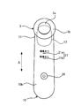
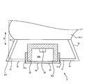
図1は、本発明の生体音測定装置の一実施形態である生体音測定装置1の概略構成を模式的に示す側面図である。図2は、図1に示す生体音測定装置1を測定者側から方向Bに見た模式図である。図3は、図2に示す生体音測定装置1を被検体側から見た模式図である。図4は、図1に示す生体音測定装置1の音測定ユニット3の断面模式図である。
図1は、本発明の生体音測定装置の一実施形態である生体音測定装置1の概略構成を模式的に示す側面図である。図2は、図1に示す生体音測定装置1を測定者側から方向Bに見た模式図である。図3は、図2に示す生体音測定装置1を被検体側から見た模式図である。図4は、図1に示す生体音測定装置1の音測定ユニット3の断面模式図である。
図1から図3に示すように、生体音測定装置1は、樹脂又は金属等の筐体で構成された方向Aに延びる柱状の把持部10を有し、この把持部10の一端側にはヘッド部11が設けられている。把持部10は、測定者によって把持される部分である。
把持部10の内部には、生体音測定装置1の全体を統括制御する統括制御部(図示省略)、動作に必要な電圧を供給する電池(図示省略)、及び図3に示す表示部21等が設けられている。
統括制御部は、各種のプロセッサ、RAM(Random Access Memory)、及びROM(Read Only Memory)等を含み、プログラムにしたがって生体音測定装置1の各ハードウェアの制御等を行う。
図1及び図4に示すように、ヘッド部11には、把持部10の長手方向Aと交差する方向の一方側(図1及び図4において下方側)へ突出する音測定ユニット3が設けられている。この音測定ユニット3の先端には、被検者の体表面Sに接触される接触面30が設けられている。
接触面30は、体表面Sからの圧力を受けるために必要な平面である例えば円状の受圧領域3a(図3参照)と、体表面Sとの接触面積を大きくするために設けられた、受圧領域3aの周囲に形成された平面である例えば円環状の拡張領域3b(図3参照)と、により構成されている。図1及び図4の例では、受圧領域3aは、拡張領域3bよりも体表面S側に僅かに突出しているが、拡張領域3bと同一面に形成されていてもよい。図1に示す方向Bは、接触面30に垂直な方向であり、把持部10の長手方向Aに対して交差している。
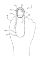
図2に示すように、接触面30に垂直な方向Bに見た状態において、把持部10の音測定ユニット3側と反対側の面10aには、音測定ユニット3と重なる部分に、測定者の手Haの例えば人差し指Fを置くための凹部12が形成されている。
図1及び図2に示すように、生体音測定装置1は、把持部10の凹部12に測定者の手Haの人差し指Fが置かれ、把持部10が手Haにより把持された状態で、音測定ユニット3の受圧領域3aを含む接触面30がこの人差し指Fによって体表面Sに押圧されて使用される。
図4に示すように、音測定ユニット3は、MEMS(Micro Electro Mechanical Systems)型マイクロフォン又は静電容量型マイクロフォン等の音検出器33と、音検出器33を収容する収容空間32bを形成しかつ開口32aを有する有底筒状のハウジング32と、開口32aを収容空間32bの外側から閉じて体表面Sからの圧力を受ける受圧領域3aを形成するカバー34と、カバー34を露出させた状態にてハウジング32及びカバー34を収容する、把持部10によって支持された筐体31と、を備える。
ハウジング32は、樹脂又は金属等の空気より音響インピーダンスが高くかつ剛性の高い材料によって構成されている。ハウジング32は、密閉状態において、収容空間32bの内部に、外部から音が伝わらないように、音検出器33の検出周波数帯の音を反射する材料にて構成されていることが好ましい。
カバー34は、有底筒状の部材であり、その中空部の形状は、ハウジング32の外壁形状とほぼ一致している。カバー34は、音響インピーダンスが人体、空気、又は、水に近い素材でかつ生体適合性の良い可撓性を有する材料によって構成される。カバー34の材料としては、例えばシリコーン又はエラストマ等が用いられる。
筐体31は、例えば樹脂等によって構成されている。筐体31には、把持部10側と反対側の端部に開口31aが形成されており、この開口31aからカバー34の一部が突出して露出した状態となっている。この筐体31から露出するカバー34の表面が上記の受圧領域3aを形成している。
この受圧領域3aが体表面Sに密着した状態になると、生体の肺音によって生じる体表面Sの振動がカバー34を振動させる。カバー34が振動すると、この振動によって収容空間32bの内圧が変動し、この内圧変動によって、肺音に応じた電気信号が音検出器33によって検出されることになる。
筐体31の把持部10から突出している部分の外面は、円環状の平面からなる上記の拡張領域3bと、拡張領域3bの外周縁と把持部10とを繋ぐテーパ面3cと、から構成されている。テーパ面3cは、外径が把持部10側から拡張領域3b側に向かって連続的に大きくなる面である。
図2に示すように、音測定ユニット3と把持部10とは部分的に重なっている。図2において、音測定ユニット3のうちの把持部10よりも外側に位置する非重なり部分31bには上述した接触面30が含まれている。そして、非重なり部分31bの接触面30に平行な方向の幅は、方向Bにおける接触面30の位置(拡張領域3bの位置と定義する)である第一位置において最大となっている。また、非重なり部分31bの接触面30に平行な方向の幅は、方向Bにおける第一位置よりも把持部10側の位置では、第一位置における幅よりも小さくなっている。
言い換えると、非重なり部分31bの接触面30に平行な断面での断面積(非重なり部分31bの外縁で囲まれる領域の面積)は、第一位置において最大となり、且つ、第一位置よりも把持部10側の位置では、第一位置における断面積よりも小さい断面積となっている。
図3に示すように、把持部10の表面のうちの、接触面30が体表面Sに接触された状態における体表面S側の面10bには、表示部21と、操作部20と、が設けられている。
表示部21は、LED(Light Emitting Diode)等の発光素子を含む発光部21a、21bを備える。把持部10の面10bにおいて、発光部21aの上側の隣には“喘鳴あり”の文字が印字されており、発光部21bの上側の隣には“喘鳴なし”の文字が印字されている。
把持部10に含まれる上記の統括制御部は、表示部21によって喘鳴の検出結果(生体音の解析結果)の報知を行う。具体的には、統括制御部は、音検出器33によって検出された肺音を解析した結果、肺音に喘鳴が含まれると判断した場合には、発光部21bを消灯し、発光部21aを発光させて、喘鳴が検出されたことを測定者に報知する。また、統括制御部は、肺音に喘鳴が含まれないと判断した場合には、発光部21aを消灯し、発光部21bを発光させて、喘鳴が検出されなかったことを測定者に報知する。なお、表示部21として発光部21aのみを用い、統括制御部は、測定結果に応じて発光部21aの発光色を変えることで、喘鳴の有無を報知するようにしてもよい。
図3に示すように、生体音測定装置1においては、把持部10の長手方向Aに垂直な方向(図3の紙面の手前から奥に向かう方向)に見た状態において、把持部10の面10bにおける凹部12と重なる領域の隣に表示部21が設けられ、面10bにおける表示部21よりも把持部10の他端側の位置に操作部20が設けられている。
操作部20は、装置の電源オン、装置の電源オフ、及び生体音の測定開始等の各種操作を行うためのインタフェースである。操作部20は、少なくとも装置の電源のオンオフを行うためのものであればよい。操作部20は、押下することで指示を入力できるボタンやスイッチの他、接触することで指示を入力できるセンサにより構成される。
(生体音測定装置1の効果)
以上のように、生体音測定装置1によれば、生体音の解析結果を表示するための表示部21が、把持部10における体表面S側の面10bに設けられている。つまり、表示部21は、接触面30を体表面Sに接触させて生体音の測定を実施している間は測定者から視認不能となる。このため、測定者は生体音の測定に集中することができる。これにより、測定中に接触面30と体表面Sとの接触状態が変化する等の事象を防いで、生体音の測定精度を確保することができる。
以上のように、生体音測定装置1によれば、生体音の解析結果を表示するための表示部21が、把持部10における体表面S側の面10bに設けられている。つまり、表示部21は、接触面30を体表面Sに接触させて生体音の測定を実施している間は測定者から視認不能となる。このため、測定者は生体音の測定に集中することができる。これにより、測定中に接触面30と体表面Sとの接触状態が変化する等の事象を防いで、生体音の測定精度を確保することができる。
また、生体音測定装置1によれば、把持部10における体表面S側の面10bに設けられた表示部21に生体音の解析結果が表示される。このため、測定者は、把持部10の把持姿勢を変えることなく、表示部21を確認することができる。この結果、生体音の測定作業開始から解析結果の確認までをスムーズに行うことができ、測定者の負担を軽減することができる。
また、生体音測定装置1によれば、把持部10の面10bにおける凹部12と重なる領域の隣、言い換えると、音測定ユニット3の近傍に表示部21が設けられている。このため、測定者が手Haにて把持部10を把持した状態であっても、表示部21が手Haによって隠れにくくなる。したがって、解析結果の確認をよりスムーズに行うことが可能となる。
また、生体音測定装置1によれば、表示部21が1つ又は複数の発光素子を含み、この発光素子の発光位置又は発光色を変更することによって生体音の解析結果を表示する。このため、把持部10の小型化、低コスト化、省エネ化が可能となる。また、例えば、乳幼児等の就寝中に生体音測定装置1を利用する場合を想定すると、発光素子の僅かな明かりによって解析結果が表示されることで、乳幼児の就寝を妨げるのを防ぐことができる。
また、生体音測定装置1によれば、操作部20が、把持部10における体表面S側の面10bに設けられている。このため、接触面30を体表面Sに接触させて生体音の測定を実施している間は、測定者の指が操作部20には触れにくくなり、測定中における誤操作を防ぐことができる。また、測定終了後、測定者は、表示部21を確認した後、そのまま例えば親指で操作部20を操作して電源をオフにすることができる。このように、測定結果の確認から電源オフまでの作業をスムーズに行うことができ、利便性を向上させることができる。
また、生体音測定装置1によれば、音測定ユニット3の接触面30を体表面Sに接触させた状態においては、音測定ユニット3における把持部10と重なっていない非重なり部分31bの外縁がそのまま接触面30の外縁となって視認可能になる。このため、接触面30と体表面Sとの接触状態を容易に確認することができる。この結果、良好な接触状態を容易に実現することができ、生体音の測定精度を向上させることが可能となる。
また、生体音測定装置1によれば、音測定ユニット3の筐体31の接触面30を除く側面が接触面30から把持部10に向かって径(幅)の小さくなるテーパ面3cとなっている。このため、接触面30の面積を大きくして体表面Sとの接触を安定的に行うことを可能としながら、テーパ面3cと把持部10との間に衣服や骨等との干渉を避けるためのスペースを確保することができる。この結果、生体音の測定開始までの準備作業をスムーズに行うことが可能となる。特に、肺音から喘鳴を検出する装置においては、被検体が乳幼児等であることが想定される。乳幼児は頻繁に動くことが想定されるため、この作業をスムーズに行えることで、測定者の負担を軽減することができる。
また、生体音測定装置1によれば、把持部10の長手方向(方向A)と接触面30とが交差している。このため、接触面30を体表面Sに接触させている状態においては、把持部10が体表面Sに平行とならない。このような構成においては、非重なり部分31bの外縁がそのまま接触面30の外縁として視認可能になることで、把持部10の向きとは関係なく、接触面30と体表面Sとの接触状態を直感的に把握できるようになる。この結果、測定者の負担を軽減しながら、生体音の測定精度を向上させることが可能となる。
(生体音測定装置1の変形例)
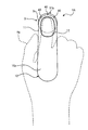
図5は、図1の生体音測定装置1の変形例である生体音測定装置1Aの構成を示す図であり、図2に対応する図である。生体音測定装置1Aは、非重なり部分31bに3つの発光部40が追加された点を除いては、生体音測定装置1と同じ構成である。
図5は、図1の生体音測定装置1の変形例である生体音測定装置1Aの構成を示す図であり、図2に対応する図である。生体音測定装置1Aは、非重なり部分31bに3つの発光部40が追加された点を除いては、生体音測定装置1と同じ構成である。
発光部40は、LED等の発光素子によって光を発するものであり、例えば筐体31に、一部が露出する状態にて埋設されている。発光部40は、統括制御部によって制御される。
例えば、統括制御部は、接触面30と体表面Sとの密着状態を判定し、密着状態が生体音の測定に適さない状態になっていると判定した場合には、発光部40から光を発光させる。または、統括制御部は、生体音の測定を行っている間は、測定中であることを測定者に報知するために、3つの発光部40を予め決めたパターンにて順次光らせる制御を行う。統括制御部は、生体音の測定処理の進捗が進むにつれて、発光させる発光部40の数を増やしていく制御を行ってもよい。
このように、接触面30を体表面Sに接触させている状態でも測定者から視認可能となる非重なり部分31bに発光部40があることで、図5に示すように、手Haで大部分が隠れてしまう生体音測定装置であっても、測定者に対する解析結果以外の様々な報知が可能となる。生体音測定装置1では、解析結果の表示は面10bに設けられた表示部21にて行い、生体音の測定中における測定者への報知に関しては発光部40にて行うことで、測定者を測定作業に集中させて測定精度を向上させつつ、解析結果の確認をスムーズに行うことが可能になる。
なお、生体音測定装置1Aに含まれる発光部40の数は3つに限らず、1つ、2つ、又は4つ以上であってもよい。
<その他の変形例>
表示部21は、生体音の解析結果を測定者に報知できるものであれば何でもよく、例えば有機EL(electro-luminescence)パネル又は液晶表示パネルによって解析結果を画像として表示するものであってもよい。
表示部21は、生体音の解析結果を測定者に報知できるものであれば何でもよく、例えば有機EL(electro-luminescence)パネル又は液晶表示パネルによって解析結果を画像として表示するものであってもよい。
表示部21と操作部20の位置は逆であってもよい。また、面10bには少なくとも表示部21が設けられていればよく、操作部20は例えば面10aに設けられていてもよい。
生体音測定装置1、1Aにおいて、把持部10の長手方向(方向A)と接触面30とが平行になる構成であってもよい。また、筐体31の側面はテーパ面3cではなく、例えば方向Bに平行な面であってもよい。また、音測定ユニット3は、方向Bから見た状態において把持部10によって完全に隠れる構成(非重なり部分31bを有しない構成)であってもよい。
以上、図面を参照しながら各種の実施の形態について説明したが、本発明はかかる例に限定されないことは言うまでもない。当業者であれば、特許請求の範囲に記載された範疇内において、各種の変更例又は修正例に想到し得ることは明らかであり、それらについても当然に本発明の技術的範囲に属するものと了解される。また、発明の趣旨を逸脱しない範囲において、上記実施の形態における各構成要素を任意に組み合わせてもよい。
なお、本出願は、2019年1月11日出願の日本特許出願(特願2019-3484)に基づくものであり、その内容は本出願の中に参照として援用される。
1、1A 生体音測定装置
3 音測定ユニット
10 把持部
10a、10b 面
11 ヘッド部
12 凹部
3a 受圧領域
3b 拡張領域
3c テーパ面
30 接触面
31 筐体
31a、32a 開口
31b 非重なり部分
32 ハウジング
32b 収容空間
33 音検出器
34 カバー
20 操作部
21 表示部
21a、21b、40 発光部
S 体表面
Ha 手
F 人差し指
3 音測定ユニット
10 把持部
10a、10b 面
11 ヘッド部
12 凹部
3a 受圧領域
3b 拡張領域
3c テーパ面
30 接触面
31 筐体
31a、32a 開口
31b 非重なり部分
32 ハウジング
32b 収容空間
33 音検出器
34 カバー
20 操作部
21 表示部
21a、21b、40 発光部
S 体表面
Ha 手
F 人差し指
Claims (5)
- 被検体の生体音を測定する生体音測定装置であって、
前記被検体の体表面に接触される接触面を含む音測定ユニットと、
前記音測定ユニットを支持し、且つ測定者によって把持される把持部と、
前記把持部に設けられた、前記音測定ユニットにより測定された生体音の解析結果を表示する表示部と、を備え、
前記把持部は、前記音測定ユニットの背面に前記測定者の人差し指が載置された状態にて前記測定者により把持されるものであり、
前記接触面が前記体表面と接触した状態において、前記把持部における前記体表面側の面に前記表示部が設けられている生体音測定装置。 - 請求項1記載の生体音測定装置であって、
前記表示部は1つ又は複数の発光素子を含み、前記発光素子の発光位置又は発光色を変更することによって前記解析結果を表示する生体音測定装置。 - 請求項1又は2記載の生体音測定装置であって、
前記接触面が前記体表面と接触した状態において、前記把持部における前記体表面側の前記面には、少なくとも電源オンオフを行うための操作部が更に設けられている生体音測定装置。 - 請求項3記載の生体音測定装置であって、
前記表示部は、前記音測定ユニットと前記操作部との間に設けられている生体音測定装置。 - 請求項1から4のいずれか1項記載の生体音測定装置であって、
前記把持部は、前記人差し指を載置するための凹部を有し、
前記表示部は、前記面のうち、前記把持部の長手方向に垂直な方向から見た状態において前記凹部と重なる領域の隣に設けられている生体音測定装置。
Priority Applications (3)
| Application Number | Priority Date | Filing Date | Title |
|---|---|---|---|
| CN201980082202.6A CN113226189A (zh) | 2019-01-11 | 2019-12-18 | 生物体声音测定装置 |
| DE112019005856.8T DE112019005856B4 (de) | 2019-01-11 | 2019-12-18 | Vorrichtung zur messung biologischer geräusche |
| US17/305,488 US11857360B2 (en) | 2019-01-11 | 2021-07-08 | Biological sound measurement device |
Applications Claiming Priority (2)
| Application Number | Priority Date | Filing Date | Title |
|---|---|---|---|
| JP2019003484A JP7206928B2 (ja) | 2019-01-11 | 2019-01-11 | 生体音測定装置 |
| JP2019-003484 | 2019-01-11 |
Related Child Applications (1)
| Application Number | Title | Priority Date | Filing Date |
|---|---|---|---|
| US17/305,488 Continuation US11857360B2 (en) | 2019-01-11 | 2021-07-08 | Biological sound measurement device |
Publications (1)
| Publication Number | Publication Date |
|---|---|
| WO2020145058A1 true WO2020145058A1 (ja) | 2020-07-16 |
Family
ID=71521304
Family Applications (1)
| Application Number | Title | Priority Date | Filing Date |
|---|---|---|---|
| PCT/JP2019/049679 Ceased WO2020145058A1 (ja) | 2019-01-11 | 2019-12-18 | 生体音測定装置 |
Country Status (5)
| Country | Link |
|---|---|
| US (1) | US11857360B2 (ja) |
| JP (1) | JP7206928B2 (ja) |
| CN (1) | CN113226189A (ja) |
| DE (1) | DE112019005856B4 (ja) |
| WO (1) | WO2020145058A1 (ja) |
Citations (7)
| Publication number | Priority date | Publication date | Assignee | Title |
|---|---|---|---|---|
| JP2007209609A (ja) * | 2006-02-10 | 2007-08-23 | Omron Healthcare Co Ltd | 携帯型心電計 |
| JP2010522037A (ja) * | 2007-03-23 | 2010-07-01 | スリーエム イノベイティブ プロパティズ カンパニー | 異種モジュール受入用インターフェースを備えたモジュール式電子生体内感知装置 |
| JP2016158806A (ja) * | 2015-02-27 | 2016-09-05 | オムロンヘルスケア株式会社 | 喘鳴検出装置 |
| US20160296200A1 (en) * | 2015-01-15 | 2016-10-13 | Jose Luis Hinojosa | MD (The Master Diagnostician) |
| JP2017060598A (ja) * | 2015-09-25 | 2017-03-30 | テルモ株式会社 | シャント振動情報検出装置 |
| JP2018503493A (ja) * | 2015-01-28 | 2018-02-08 | レスピディーエックス・リミテッド | 生命徴候を測定するための経口挿入プローブおよび方法 |
| JP2018102727A (ja) * | 2016-12-27 | 2018-07-05 | オムロンヘルスケア株式会社 | 生体音測定装置 |
Family Cites Families (20)
| Publication number | Priority date | Publication date | Assignee | Title |
|---|---|---|---|---|
| DE7045017U (de) * | 1970-12-05 | 1971-03-18 | Fa W Heselmeier | Stethoskop-bruststueck mit trichter |
| FI98981C (fi) * | 1994-10-28 | 1997-09-25 | Tommi Sakari Lukkarinen | Kädessä pidettävä tallentava audiovisuaalinen stetoskooppi |
| US5663532A (en) * | 1995-11-27 | 1997-09-02 | Minnesota Mining And Manufacturing Company | Ergonometric stethoscope chestpiece |
| US7182733B2 (en) * | 2003-08-20 | 2007-02-27 | Sauerland Keith A | Cordless stethoscope for hazardous material environments |
| US20080228095A1 (en) * | 2007-03-15 | 2008-09-18 | Richardson Mary | Medical device |
| US8594339B2 (en) * | 2007-03-23 | 2013-11-26 | 3M Innovative Properties Company | Power management for medical sensing devices employing multiple sensor signal feature detection |
| WO2013184437A2 (en) * | 2012-06-05 | 2013-12-12 | 3M Innovative Properties Company | Electronic stethoscope system for telemedicine applications |
| US20130131465A1 (en) | 2010-07-26 | 2013-05-23 | Sharp Kabushiki Kaisha | Biomeasurement device, biomeasurement method, control program for a biomeasurement device, and recording medium with said control program recorded thereon |
| JP5701533B2 (ja) * | 2010-07-26 | 2015-04-15 | シャープ株式会社 | 測定位置判定装置、測定位置判定方法、制御プログラムおよび記録媒体 |
| JPWO2013089072A1 (ja) * | 2011-12-13 | 2015-04-27 | シャープ株式会社 | 情報管理装置、情報管理方法、情報管理システム、聴診器、情報管理プログラム、測定システム、制御プログラムおよび記録媒体 |
| CN105877775A (zh) * | 2014-09-25 | 2016-08-24 | 俞泓 | 记录心跳参数的电子听诊装置 |
| JP6414487B2 (ja) | 2015-02-27 | 2018-10-31 | オムロンヘルスケア株式会社 | 喘鳴関連情報表示装置 |
| AU2016321233B2 (en) * | 2015-09-08 | 2019-10-31 | Medwand Solutions, Inc. | Integrated medical device and home based system to measure and report vital patient physiological data via telemedicine |
| CN105310714B (zh) * | 2015-11-12 | 2019-01-11 | 成都云卫康医疗科技有限公司 | 一种集成血氧测量的可视化听诊器 |
| CN105769386B (zh) * | 2016-03-30 | 2017-10-31 | 广东医学院 | 手持式人工机械瓣膜血栓分析仪 |
| JP2018102849A (ja) * | 2016-12-28 | 2018-07-05 | オムロンヘルスケア株式会社 | 生体音測定装置 |
| TWI624246B (zh) * | 2017-01-25 | 2018-05-21 | 美盛醫電股份有限公司 | 血壓量測裝置及其方法 |
| CN207785173U (zh) * | 2017-04-24 | 2018-08-31 | 重庆医科大学附属永川医院 | 一种实时外放式智能听诊器 |
| CN107693044A (zh) * | 2017-11-15 | 2018-02-16 | 广东顺德西安交通大学研究院 | 冠心病监测诊断设备 |
| JP2020193484A (ja) | 2019-05-28 | 2020-12-03 | 清水建設株式会社 | コンクリート構造物の施工方法および施工装置 |
-
2019
- 2019-01-11 JP JP2019003484A patent/JP7206928B2/ja active Active
- 2019-12-18 CN CN201980082202.6A patent/CN113226189A/zh active Pending
- 2019-12-18 DE DE112019005856.8T patent/DE112019005856B4/de active Active
- 2019-12-18 WO PCT/JP2019/049679 patent/WO2020145058A1/ja not_active Ceased
-
2021
- 2021-07-08 US US17/305,488 patent/US11857360B2/en active Active
Patent Citations (7)
| Publication number | Priority date | Publication date | Assignee | Title |
|---|---|---|---|---|
| JP2007209609A (ja) * | 2006-02-10 | 2007-08-23 | Omron Healthcare Co Ltd | 携帯型心電計 |
| JP2010522037A (ja) * | 2007-03-23 | 2010-07-01 | スリーエム イノベイティブ プロパティズ カンパニー | 異種モジュール受入用インターフェースを備えたモジュール式電子生体内感知装置 |
| US20160296200A1 (en) * | 2015-01-15 | 2016-10-13 | Jose Luis Hinojosa | MD (The Master Diagnostician) |
| JP2018503493A (ja) * | 2015-01-28 | 2018-02-08 | レスピディーエックス・リミテッド | 生命徴候を測定するための経口挿入プローブおよび方法 |
| JP2016158806A (ja) * | 2015-02-27 | 2016-09-05 | オムロンヘルスケア株式会社 | 喘鳴検出装置 |
| JP2017060598A (ja) * | 2015-09-25 | 2017-03-30 | テルモ株式会社 | シャント振動情報検出装置 |
| JP2018102727A (ja) * | 2016-12-27 | 2018-07-05 | オムロンヘルスケア株式会社 | 生体音測定装置 |
Also Published As
| Publication number | Publication date |
|---|---|
| US20210330280A1 (en) | 2021-10-28 |
| JP7206928B2 (ja) | 2023-01-18 |
| US11857360B2 (en) | 2024-01-02 |
| CN113226189A (zh) | 2021-08-06 |
| DE112019005856B4 (de) | 2024-12-24 |
| DE112019005856T5 (de) | 2021-09-09 |
| JP2020110356A (ja) | 2020-07-27 |
Similar Documents
| Publication | Publication Date | Title |
|---|---|---|
| CN107184231B (zh) | 生物体声音测定装置 | |
| US20120271180A1 (en) | Multifunctional mouse | |
| KR20200101159A (ko) | 명상 어플리케이션을 포함하는 전자 장치 | |
| US11278258B2 (en) | Biological sound measuring device, biological sound measurement support method, and biological sound measurement support program | |
| US12036064B2 (en) | Biological sound measuring device, method for operating biological sound measuring device, and program for operating biological sound measuring device | |
| US20210077056A1 (en) | Wheezing detection device and wheezing detection program | |
| US12138105B2 (en) | Biological sound measurement device, control method for biological sound measurement device, and non-transitory recording medium storing control program for biological sound measurement device | |
| CN109982632A (zh) | 便携式测量仪器 | |
| CN107203285B (zh) | 指示体 | |
| JP2020110356A (ja) | 生体音測定装置 | |
| WO2020145060A1 (ja) | 生体音測定装置 | |
| WO2020145062A1 (ja) | 生体音測定装置 | |
| JP2008200432A (ja) | 振動検出デバイス | |
| WO2021192862A1 (ja) | 喘鳴検出装置 | |
| US12383221B2 (en) | Biological sound measuring device, biological sound measurement support method, and biological sound measurement support program | |
| JP6628919B1 (ja) | 電子体温計 | |
| JP2021153854A (ja) | 喘鳴検出装置 | |
| WO2020145061A1 (ja) | 生体音測定装置 | |
| JPWO2018146952A1 (ja) | 入力装置 | |
| JP6686821B2 (ja) | 電子機器 | |
| JP2026001547A (ja) | 電子聴診装置及び振動検出装置 | |
| JP2021177798A (ja) | マッサージ器 | |
| JP2012070970A (ja) | 耳式体温計 |
Legal Events
| Date | Code | Title | Description |
|---|---|---|---|
| 121 | Ep: the epo has been informed by wipo that ep was designated in this application |
Ref document number: 19909330 Country of ref document: EP Kind code of ref document: A1 |
|
| 122 | Ep: pct application non-entry in european phase |
Ref document number: 19909330 Country of ref document: EP Kind code of ref document: A1 |