WO2020144892A1 - 中子造型方法及び中子造型装置 - Google Patents
中子造型方法及び中子造型装置 Download PDFInfo
- Publication number
- WO2020144892A1 WO2020144892A1 PCT/JP2019/034833 JP2019034833W WO2020144892A1 WO 2020144892 A1 WO2020144892 A1 WO 2020144892A1 JP 2019034833 W JP2019034833 W JP 2019034833W WO 2020144892 A1 WO2020144892 A1 WO 2020144892A1
- Authority
- WO
- WIPO (PCT)
- Prior art keywords
- temperature
- mold
- press
- kneading
- heating
- Prior art date
- Legal status (The legal status is an assumption and is not a legal conclusion. Google has not performed a legal analysis and makes no representation as to the accuracy of the status listed.)
- Ceased
Links
Images



Classifications
-
- B—PERFORMING OPERATIONS; TRANSPORTING
- B22—CASTING; POWDER METALLURGY
- B22C—FOUNDRY MOULDING
- B22C7/00—Patterns; Manufacture thereof so far as not provided for in other classes
- B22C7/06—Core boxes
-
- B—PERFORMING OPERATIONS; TRANSPORTING
- B22—CASTING; POWDER METALLURGY
- B22C—FOUNDRY MOULDING
- B22C19/00—Components or accessories for moulding machines
- B22C19/04—Controlling devices specially designed for moulding machines
-
- B—PERFORMING OPERATIONS; TRANSPORTING
- B22—CASTING; POWDER METALLURGY
- B22C—FOUNDRY MOULDING
- B22C13/00—Moulding machines for making moulds or cores of particular shapes
- B22C13/12—Moulding machines for making moulds or cores of particular shapes for cores
- B22C13/16—Moulding machines for making moulds or cores of particular shapes for cores by pressing through a die
-
- B—PERFORMING OPERATIONS; TRANSPORTING
- B22—CASTING; POWDER METALLURGY
- B22C—FOUNDRY MOULDING
- B22C15/00—Moulding machines characterised by the compacting mechanism; Accessories therefor
- B22C15/02—Compacting by pressing devices only
-
- B—PERFORMING OPERATIONS; TRANSPORTING
- B22—CASTING; POWDER METALLURGY
- B22C—FOUNDRY MOULDING
- B22C9/00—Moulds or cores; Moulding processes
- B22C9/02—Sand moulds or like moulds for shaped castings
-
- B—PERFORMING OPERATIONS; TRANSPORTING
- B22—CASTING; POWDER METALLURGY
- B22C—FOUNDRY MOULDING
- B22C9/00—Moulds or cores; Moulding processes
- B22C9/10—Cores; Manufacture or installation of cores
-
- B—PERFORMING OPERATIONS; TRANSPORTING
- B22—CASTING; POWDER METALLURGY
- B22C—FOUNDRY MOULDING
- B22C9/00—Moulds or cores; Moulding processes
- B22C9/12—Treating moulds or cores, e.g. drying, hardening
Definitions
- the present disclosure relates to a core molding method and a core molding apparatus.
- Patent Document 1 describes a core molding apparatus in which kneading sand is put in a mold, the mold is heated, and the kneading sand is cured along the shape of the mold.
- This apparatus includes a mold having a mold temperature sensor that measures the temperature of the mold, a heating device that heats the mold, and a temperature controller that controls the heating temperature of the heating device with respect to the mold.
- the temperature controller sets the heating temperature at each location of the mold and causes the heating device to heat the mold.
- the mold temperature sensor feeds back the temperature of each place of the mold to the temperature controller.
- the temperature controller appropriately controls the heating temperature at each location of the mold based on the feedback.
- the present disclosure provides a core molding method and a core molding apparatus that suppress sticking of a core to a mold.
- the core molding method according to the present disclosure is a method of molding a core using a mold in which kneading sand is press-fitted, and the mold temperature is set to a temperature higher than a predetermined firing temperature. Heating the mold, pressing the kneading sand into the heated mold, holding the temperature of the mold into which the kneading sand is pressed at the firing temperature, Removing the child.
- the mold is heated to a temperature higher than a predetermined firing temperature.
- the press-fitting step the kneading sand is press-fitted into the heated mold.
- the holding step the temperature of the mold into which the kneading sand is pressed is held at the baking temperature which is the temperature of the mold when baking the kneading sand.
- the taking-out step the core is taken out of the mold after the holding step.
- the heating step the mold is heated to a temperature higher than the firing temperature before the kneading sand is pressed.
- the temperature of the mold is baked by pressing the kneading sand. It is possible to prevent the temperature from becoming lower than the temperature and the difference between the mold temperature and the firing temperature from increasing. As a result, this method reduces the time for firing the kneading sand at a temperature lower than the firing temperature, as compared with the case where the mold is not heated to a temperature higher than the firing temperature before the kneading sand is pressed. be able to. Therefore, this method can suppress sticking of the core to the mold.
- the core molding method further includes a step of measuring the first temperature of the mold at the end of the heating step and a step of measuring the second temperature of the mold at the end of the press-fitting step. Then, the heating step, the first temperature measuring step, the press-fitting step, the second temperature measuring step, the holding step, and the taking-out step are repeatedly executed in order, and the heating step after the taking-out step performs measurement.
- the die pre-temperature may be determined based on the determined first temperature, the measured second temperature, and the firing temperature, and the die may be heated based on the determined pre-temperature.
- the step of heating, the step of measuring the first temperature, the step of press-fitting, the step of measuring the second temperature, the step of holding, and the step of taking out are sequentially executed, and these are repeatedly executed as one cycle.
- the preliminary temperature of the mold is determined based on the measured first temperature, the measured second temperature, and the firing temperature.
- the mold is heated based on the pre-temperature in the heating step in the second and subsequent cycles.
- the pre-temperature is determined by utilizing the relationship among the first temperature, the second temperature, and the firing temperature that have been used. Therefore, this method can appropriately determine the prior temperature using the past data.
- the core molding method further includes a step of measuring the first temperature of the mold at the end of the heating step, and the step of holding the kneading sand is pressed in from the start of temperature control of the mold.
- the method includes a step of measuring an adjustment time until the mold temperature is changed to a predetermined firing temperature, and a heating step, a first temperature measuring step, a press-fitting step, a holding step, and a removing step.
- the pre-temperature of the mold is determined based on the measured first temperature and the measured adjustment time, and the mold is determined based on the determined pre-temperature. You may heat.
- the step of heating, the step of measuring the first temperature, the step of press-fitting, the step of holding, and the step of taking out are sequentially executed, and these are repeatedly executed as one cycle.
- the preliminary temperature of the mold is determined based on the measured first temperature and the adjustment time.
- the mold is heated based on the pre-temperature in the heating step in the second and subsequent cycles.
- the pre-temperature is determined by utilizing the relationship between the first temperature and the adjustment time that have been previously used. Therefore, this method can appropriately determine the prior temperature using the past data.
- the second temperature is higher than the firing temperature, and the difference between the second temperature and the firing temperature is higher than a predetermined first threshold value.
- it may further include a step of notifying an abnormality.
- the second temperature may be higher than the sum of the firing temperature and the first threshold value even if the kneading sand is pressed into the mold in the pressing step.
- the core molded in this state may have lower quality than the core molded at an appropriate firing temperature. This method can notify the possibility of core quality deterioration by notifying the abnormality when the above-mentioned state is reached.
- the core molding method may further include a step of heating the kneading sand before the step of press-fitting.
- the kneading sand is heated before the press-fitting step, so that the temperature decrease of the mold in the press-fitting step is suppressed as compared with the case where the kneading sand is not heated. Accordingly, this method can prevent the temperature of the mold from becoming lower than the firing temperature due to the press-fitting of the kneading sand, and the difference between the temperature of the die and the firing temperature becoming large.
- the mold is not heated to a temperature higher than the firing temperature before press-fitting the kneading sand, and the temperature is lower than the firing temperature as compared with the case where the kneading sand is not heated.
- the time for firing the kneaded sand can be reduced.
- this method can reduce the heating amount of the mold in the heating step as compared with the case where the kneading sand is not heated.
- a core molding device that is another aspect of the present disclosure is a device that molds a core by using a mold into which kneading sand is pressed, and a mold for firing the kneading sand and the kneading sand in the mold.
- Press-fitting device for press-fitting mold heat controller for controlling mold temperature, mold temperature sensor for measuring mold temperature, press-fitting device, mold heat controller and mold temperature sensor And a controller connected to the controller, wherein the controller heats the mold so that the temperature of the mold is higher than a predetermined firing temperature using the mold heat controller,
- the step of press-fitting the kneading sand into the heated mold using the press-fitting device and the temperature of the mold into which the kneading sand is press-fitted are maintained at the firing temperature using the mold heat controller and the mold temperature sensor.
- the step and the step of removing the core from the mold after the step of holding are performed.
- the mold in the heating step, is heated to a temperature higher than a predetermined firing temperature by the control of the mold heat controller controlled by the controller.
- the step of press-fitting the kneading sand is press-fitted into the heated mold by the press-fitting device controlled by the controller.
- the step of holding the temperature of the mold in which the kneading sand is press-fitted by the heat controller for mold, the temperature sensor for mold, and the control unit is set to the baking temperature which is the temperature of the mold when baking the kneading sand. Retained.
- the taking-out step the core is taken out of the mold after the holding step.
- the mold heat controller in the heating step heats the mold to a temperature higher than the firing temperature before the kneading sand is pressed. For this reason, compared with the case where the mold is not heated before the kneading sand is press-fitted or the mold is maintained at the baking temperature, the temperature of the mold is baked by the press-fitting of the kneading sand. It is possible to prevent the temperature from becoming lower than the temperature and the difference between the mold temperature and the firing temperature from increasing.
- this device reduces the time for firing the kneading sand at a temperature lower than the firing temperature, as compared with the case where the mold is not heated to a temperature higher than the firing temperature before the kneading sand is pressed. be able to. Therefore, this device can suppress sticking of the core to the mold.
- the core molding apparatus further includes a recording unit that is connected to the mold temperature sensor and the control unit and records the temperature of the mold, and the control unit heats using the mold temperature sensor. Measure the first temperature of the mold at the end of the step and record it in the recording unit, and measure the second temperature of the mold at the end of the step of press-fitting using the mold temperature sensor and record it in the recording unit. And the step of heating, the step of measuring the first temperature, the step of press-fitting, the step of measuring the second temperature, the step of holding, and the step of taking out are repeatedly executed in order, and after the step of taking out.
- the die pre-temperature is determined based on the first temperature and the second temperature recorded in the recording unit and the firing temperature, and the die heat controller is activated based on the determined pre-temperature. It may be used to heat the mold.
- the step of heating, the step of measuring the first temperature, the step of press-fitting, the step of measuring the second temperature, the step of holding, and the step of taking out are sequentially executed, and these are repeatedly executed as one cycle.
- the preliminary temperature of the mold is determined based on the first temperature and the second temperature recorded in the recording unit, and the firing temperature.
- the mold is heated based on the pre-temperature in the heating step in the second and subsequent cycles.
- the pre-temperature is determined by utilizing the relationship among the first temperature, the second temperature, and the firing temperature that have been used. Therefore, this device can appropriately determine the prior temperature using the past data.
- the core molding apparatus further includes a recording unit that is connected to the mold temperature sensor and the control unit and records a temperature of the mold and a time corresponding to a temperature change of the mold.
- the method further includes a step of measuring the first temperature of the mold at the end of the heating step using the sensor and recording it in the recording unit, and the step of holding the temperature using the mold temperature sensor starts the mold temperature control.
- the press-in step, the holding step, and the take-out step are repeatedly executed in order, and in the heating step after the take-out step, the preliminary temperature of the mold is determined based on the first temperature and the adjustment time recorded in the recording section.
- the mold heat controller may be used to heat the mold based on the determined preliminary temperature.
- the step of heating, the step of measuring the first temperature, the step of press-fitting, the step of holding, and the step of taking out are sequentially executed, and these are repeatedly executed as one cycle.
- the preliminary temperature of the mold is determined based on the first temperature and the adjustment time recorded in the recording unit.
- the mold is heated based on the pre-temperature in the heating step in the second and subsequent cycles.
- the pre-temperature is determined by utilizing the relationship between the first temperature and the adjustment time that have been previously used. Therefore, this device can appropriately determine the prior temperature using the past data.
- the core molding apparatus further includes a notification unit that is connected to the control unit and that reports an abnormality, and the control unit, after the step of measuring the second temperature, the second temperature is higher than the firing temperature, and The step of causing the notification unit to notify of the abnormality when the difference between the second temperature and the firing temperature is larger than the first threshold value set in advance may be further executed.
- the second temperature may be higher than the sum of the firing temperature and the first threshold value even if the kneading sand is pressed into the mold in the pressing step.
- the core molded in this state may have lower quality than the core molded at an appropriate firing temperature.
- This device can notify the possibility of core quality deterioration by notifying the abnormality by the notifying unit when the above state is brought about.
- a kneading container that stores kneading sand and discharges the kneading sand by the press-fitting device, and a kneading container heater that is connected to the kneading container and the control unit and heats the kneading container is further provided.
- the control unit may further include the step of heating the kneading sand by heating the kneading container with the heater for the kneading container before the step of press-fitting.
- the kneading sand is heated before the press-fitting step, so that the temperature decrease of the mold in the press-fitting step is suppressed as compared with the case where the kneading sand is not heated.
- this device can prevent the temperature of the mold from becoming lower than the baking temperature due to the press-fitting of the kneading sand, and the difference between the temperature of the mold and the baking temperature becoming large.
- this device is not heated so that the mold is heated to a temperature higher than the firing temperature before the kneading sand is press-fitted, and the temperature is lower than the firing temperature as compared with the case where the kneading sand is not heated.
- the time for firing the kneaded sand can be reduced.
- this apparatus can reduce the heating amount of the mold in the heating step as compared with the case where the kneading sand is not heated.
- FIG. 1 is a flowchart showing an example of a core molding method according to the first embodiment and the second embodiment.
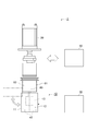
- FIG. 2 is a schematic diagram showing an example of the core molding apparatus according to the first embodiment and the second embodiment.
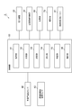
- FIG. 3 is a block diagram showing an example of functions of the core molding apparatus according to the first embodiment and the second embodiment.
- FIG. 4 is a graph showing an example in which the temperature after press-fitting is equal to or lower than the firing temperature in the process of temperature change of the mold of the core molding apparatus according to the first embodiment and the second embodiment.
- FIG. 5 is a graph showing an example in which the temperature after press-fitting is higher than the firing temperature in the process of temperature change of the mold of the core molding apparatus according to the first embodiment and the second embodiment.
- FIG. 1 is a flowchart showing an example of a core molding method according to an embodiment.
- the core molding method shown in FIG. 1 is a method of molding a core using a mold into which kneading sand is pressed.
- Kneading sand is a raw material for manufacturing cores.
- the kneading sand is, for example, refractory mineral sand or synthetic sand coated with water glass or kneaded with water glass.
- the mineral sand or synthetic sand is, for example, alumina sand, silica sand, zircon sand, or the like.
- the kneading sand is pressed into the heated mold.
- the kneading sand is fired inside the mold at the firing temperature T.
- the firing temperature T is a temperature at which the kneading sand is fired, which is suitable for molding the core.
- the firing temperature T is appropriately set depending on the type of kneading sand, core, or mold.
- the kneading sand is fired inside the mold and hardened along the inner wall of the mold to mold the core.
- the flowchart shown in FIG. 1 is implemented by the core molding apparatus shown in FIG. 2, for example.
- FIG. 2 is a schematic diagram showing an example of the core molding apparatus according to the embodiment.
- the core molding apparatus 1 includes a mold 10, a press-fitting device 20, a mold heat controller 30, a mold temperature sensor 40, and a controller 50.
- the core molding apparatus 1 may include a kneading container 80 and a kneading container heater 81.
- the mold 10 is a mold for firing the kneading sand.
- the mold 10 has, for example, a left mold 11 and a right mold 12.
- the mold 10 is used by combining a left mold 11 and a right mold 12.
- a cavity 13 is defined inside the combined left mold 11 and right mold 12.
- the left mold 11 and the right mold 12 are provided with kneading sand charging holes in the upper part in order to supply the kneading sand to the cavity 13.
- the kneading sand is pressed into the cavity 13 by the press-fitting device 20 through the kneading sand charging hole.
- the kneaded sand that has been press-fitted is fired.
- the kneading sand is hardened by firing and becomes a core.
- the core is molded in the shape of the cavity 13.
- the molded core is taken out of the mold 10.
- the left mold 11 is configured to be rotatable around its upper part after being released from the mold. By rotating the left mold 11 so that the lower end of the left mold 11 is separated from the lower end of the right mold 12, the core can be taken out from the mold 10.
- the press-fitting device 20 is a device for press-fitting the kneading sand into the mold 10.
- the press-fitting device 20 is provided above the die 10, for example.
- the press-fitting device 20 pressurizes the kneading sand into the mold 10 through the kneading sand feeding hole by applying a force to the kneading sand from the upper side to the lower side.
- the press-fitting device 20 is, for example, a piston or an air supply device.
- the press-fitting device 20 presses the kneading sand in the kneading container 80 arranged above the mold 10 into the cavity 13 of the mold 10.
- the kneading container 80 stores the kneading sand and discharges the kneading sand by the press-fitting device 20.
- the kneading container 80 is made of metal, for example.
- the kneading container 80 has, for example, a bottomed cylindrical structure with an open top, and has a discharge port at the bottom having an openable and closable valve structure.
- the kneading container 80 stores kneading sand inside. If no force is applied from above, the kneading sand will not be discharged from the bottom discharge port.
- the kneading container 80 When the kneading sand is press-fitted into the mold 10, the kneading container 80 is provided, for example, below the press-fitting device 20 and above the mold 10. The discharge port of the kneading container 80 is provided so as to be close to or in contact with the mold 10. The kneading container 80 discharges the kneading sand stored therein downward from the discharge port according to the force applied from the press-fitting device 20, and supplies the kneading sand into the cavity 13 of the mold 10.
- the kneading container heater 81 heats the kneading container 80.
- the kneading container heater 81 is provided so as to be close to or in contact with the outer surface of the kneading container 80.
- the kneading container heater 81 heats the kneading container 80 to a target temperature under the control of the control unit 50.
- the target temperature is a target temperature that is appropriately set by the control unit 50 when the kneading container 80 is heated by the control unit 50 and the kneading container heater 81.
- the core molding apparatus 1 has, for example, a kneading container temperature sensor 82.
- the kneading container temperature sensor 82 transmits the temperature of the kneading container 80 to the control unit 50.
- the mold heat controller 30 controls the temperature of the mold 10.
- the mold heat controller 30 heats, lowers or maintains the temperature of each part of the mold 10.
- the mold heat controller 30 may be provided inside the mold 10 or outside the mold 10.
- the mold heat controller 30 is, for example, a heater or a cooling water circulator.
- the mold temperature sensor 40 measures the temperature of the mold 10.
- the mold temperature sensor 40 is provided, for example, at a plurality of locations outside the mold 10.
- the mold temperature sensor 40 outputs the temperature value at each location of the mold 10 at regular intervals.
- the mold temperature sensor 40 is, for example, a thermocouple sensor.
- the mold temperature sensor 40 may be a non-contact temperature sensor.
- the control unit 50 is composed of, for example, a control device such as a computer.
- the hardware of the control unit 50 includes, for example, a CPU (Central Processing Unit), a ROM (Read Only Memory), a RAM (Random Access Memory), an A/D conversion circuit, a D/A conversion circuit, and a communication I/F (interface). )
- the CPU, ROM, RAM, A/D conversion circuit, D/A conversion circuit, and communication I/F circuit are connected to the bus.
- the A/D conversion circuit and the D/A conversion circuit are connected to the bus via the input/output I/F circuit.
- FIG. 3 is a block diagram showing an example of functions of the core molding apparatus according to the embodiment.
- the control unit 50 includes, for example, an acquisition unit 51, a measurement unit 52, a setting unit 53, a reception unit 54, a determination unit 55, and an instruction unit 56.
- the control unit 50 is connected to the press-fitting device 20, the mold heat controller 30, the mold temperature sensor 40, the recording unit 60, the notification unit 70, the kneading container heater 81, and the kneading container temperature sensor 82.
- the acquisition unit 51 acquires the temperature of the mold 10 measured by the mold temperature sensor 40.
- the acquisition unit 51 may acquire the temperature of the kneading container 80 measured by the kneading container temperature sensor 82.
- the measuring unit 52 measures the time from the predetermined temperature in the mold 10 measured by the mold temperature sensor 40 to the predetermined temperature.
- the acquisition unit 51 may be connected to the kneading container temperature sensor 82 and measure the time from a predetermined temperature in the kneading container 80 to a predetermined temperature.
- the measuring unit 52 measures the time from the start of a predetermined process to the end of a subsequent predetermined process, or until the temperature of the mold 10 reaches a predetermined temperature.
- the measuring unit 52 measures the time from the end time of the predetermined process to the start time of the subsequent predetermined process or until the temperature of the mold 10 reaches the predetermined temperature.
- the measuring unit 52 measures the time from the time when the temperature of the mold 10 reaches a predetermined temperature to the start time of a predetermined process or the end time of a predetermined process.
- the setting unit 53 determines the preliminary temperature of the mold 10 based on at least the previous temperature recorded in the recording unit 60 when there is data regarding the previous temperature in the recording unit 60.
- the pre-temperature is a target temperature when the mold heat controller 30 heats the mold 10 before the kneading sand is pressed into the mold 10 by the press-fitting device 20.
- the pre-temperature is a temperature higher than the firing temperature T.
- the setting unit 53 may determine the preliminary temperature by using the temperature of the mold 10 acquired by the acquisition unit 51 or the temperature of the kneading container 80 acquired by the acquisition unit 51.
- the setting unit 53 determines the target temperature of the kneading container 80 based on the previous temperature recorded in the recording unit 60 when there is data regarding the previous temperature in the recording unit 60.
- the target temperature is a target temperature for heating the kneading container 80 by the kneading container heater 81 in advance before the kneading sand is pressed into the mold 10 by the press-fitting device 20.
- the setting unit 53 may determine the target temperature by using the temperature of the mold 10 acquired by the acquisition unit 51, the temperature of the kneading container 80 acquired by the acquisition unit 51, or the time measured by the measurement unit 52. Good.
- the reception unit 54 receives an input of the firing temperature T.
- the receiving unit 54 receives the input of the preliminary temperature or the target temperature by the worker when the setting unit 53 cannot set the preliminary temperature or the target temperature because there is no data regarding the previous temperature according to the recording unit 60.
- the reception unit 54 may receive the input of the firing time.
- the firing time is the time from the time when the kneading sand is pressed into the mold 10 to the time when the kneading sand is fired in the mold 10.
- the reception unit 54 is, for example, a keyboard or a touch panel.
- the reception unit 54 may be integrated with the notification unit 70 using a touch panel or the like.
- the determination unit 55 compares the temperature of the mold 10 acquired by the acquisition unit 51 with the preliminary temperature or the firing temperature T set by the setting unit 53 or the receiving unit 54, and the mold heat controller 30 and It is determined whether or not the processing by the control unit 50 is continued.
- the determination unit 55 compares the temperature of the kneading container 80 acquired by the acquisition unit 51 with the target temperature set by the setting unit 53 or the reception unit 54, and performs the processing by the kneading container heater 81 and the control unit 50. Determine whether to continue.
- the instructing unit 56 instructs the mold heat controller 30 to perform heating, lowering the temperature, or maintaining the temperature based on the determination result of the determining unit 55. Based on the determination result of the determination unit 55, the instruction unit 56 instructs the kneading container heater 81 to heat, lower the temperature, or maintain the temperature.
- the core molding apparatus 1 may include a recording unit 60.
- the recording unit 60 records the temperature of the mold 10.
- the recording unit 60 records, for example, the preliminary temperature, the target temperature, and the firing temperature T.
- the recording unit 60 may record a time corresponding to a temperature change of the mold 10, such as a baking time.
- the recording unit 60 may record the temperature of the kneading container 80 and the time corresponding to the temperature change of the kneading container 80.
- the core molding apparatus 1 may include a notification unit 70.
- the notification unit 70 notifies the abnormality based on the instructions of the determination unit 55 and the instruction unit 56.
- the notification unit 70 notifies the worker of the abnormality by, for example, displaying a screen on a display terminal such as a display or outputting an alarm sound through a speaker.
- the abnormality refers to a case where the temperature of the mold 10 measured by the mold temperature sensor 40 satisfies a condition predetermined by an operator.
- the notification unit 70 may visualize and display the contents of processing performed by the control unit 50. The worker can perform an input operation on the reception unit 54 of the control unit 50 after checking the notification unit 70.
- the core molding method will be described below with reference to FIG. 1 again.
- the core molding method is executed by the control unit 50.
- the control unit 50 can repeatedly execute the processes of S1 (S11) to S8 in order.
- One cycle is to perform each of the processes from S1 (S11) to S8 of the core molding method once in order.
- S1 is the mold heat treatment in the first cycle
- S11 is the mold heat treatment in the second and subsequent cycles.
- S2 is the kneading sand heat treatment in the first cycle
- S12 is the kneading sand heat treatment in the second cycle and thereafter.
- a process of introducing kneading sand into the kneading container 80 and kneading may be provided.
- the mold heat controller 30 heats the mold 10 based on an instruction from the instruction unit 56 of the control unit 50.
- the reception unit 54 receives the preliminary temperature.
- the reception unit 54 transmits the received preliminarily temperature to the determination unit 55 and the recording unit 60.
- the recording unit 60 records the preliminary temperature.
- the instruction unit 56 instructs the mold heat controller 30 to determine the temperature of the mold 10 in advance.
- the mold 10 is heated to reach the temperature.
- the control unit 50 proceeds to the next process. In this case, the mold heat controller 30 stops heating the mold 10 and maintains the temperature of the mold 10, for example.
- the determination unit 55 makes the above determination as needed.
- the kneading container heater 81 heats the kneading container 80 based on the instruction of the instruction unit 56 of the control unit 50.
- the target temperature is received by the reception unit 54.
- the reception unit 54 transmits the received target temperature to the determination unit 55 and the recording unit 60.
- the recording unit 60 records the target temperature.
- the instructing unit 56 instructs the kneading container heater 81 to set the temperature of the kneading container 80 to the target temperature. So that the kneading container 80 is heated.
- the kneading sand is heated.
- the kneading sand is heated, for example, between 25°C and 30°C.
- the kneading sand is heated, for example, up to 40°C.
- the control unit 50 shifts to the next process.
- the instruction unit 56 causes the kneading container heater 81 to maintain the temperature of the kneading container 80.
- the determination unit 55 makes the above determination as needed.
- the kneading sand heating process (S2) in the first cycle may be performed at least before the kneading sand press-fitting process (S4).
- the controller 50 and the kneading container heater 81 may control the temperature of the kneading container 80 even during the processes after the kneading sand heating process (S2).
- the mold temperature sensor 40 is used, and the pre-press-fit temperature (an example of the first temperature) that is the temperature of the mold 10 at the end of the mold heating process (S1, S11) is It is measured and recorded in the recording unit 60.
- the acquisition unit 51 of the control unit 50 acquires the pre-press-fit temperature that is the temperature of the mold 10 measured using the mold temperature sensor 40 at the end of the mold heating process (S1, S11).
- the acquisition unit 51 transmits the pre-press-fit temperature to the recording unit 60.
- the recording unit 60 records the temperature before press fitting.
- the pre-press-fit temperature measurement process (S3) ends when the recording in the recording unit 60 ends, and the control unit 50 proceeds to the next process.
- the press-fitting device 20 In the kneading sand press-fitting process (S4), the press-fitting device 20 is used, and the kneading sand is press-fitted into the heated mold 10.
- the kneading container 80 moves under the control of the control unit 50 and is arranged below the press-fitting device 20.
- the press-fitting device 20 press-fits the kneading sand from the kneading container 80 into the mold 10 based on the press-fitting amount or the press-fitting time of the kneading sand predetermined by the control unit 50.
- the press-fitting device 20 presses the kneading sand into the cavity 13 of the mold 10 by means of a piston, for example.
- the kneading sand press-fitting process (S4) ends when a predetermined press-fitting amount or time of the kneading sand is reached.
- the press-fitting device 20 ends the press-fitting under the control of the control unit 50, and the control unit 50 proceeds to the next process.
- the kneading container 80 may be arranged below the press-fitting device 20.
- the mold temperature sensor 40 is used to measure the post-press-fit temperature (an example of the second temperature) that is the temperature of the mold 10 at the end of the kneading sand press-fit process (S4). , Is recorded in the recording unit 60.
- the acquisition unit 51 of the control unit 50 acquires the post-pressurization temperature, which is the temperature of the mold 10 measured using the mold temperature sensor 40, at the end of the kneading sand press-fitting process (S4).
- the acquisition unit 51 transmits the temperature after press fitting to the recording unit 60.
- the recording unit 60 records the temperature after press fitting.
- the post-press-fit temperature measurement process (S5) ends when recording in the recording unit 60 ends, and the control unit 50 proceeds to the next process.
- the reception unit 54 receives the input of the first threshold value for the difference between the temperature after press-fitting and the firing temperature T when the temperature after press-fitting is higher than the firing temperature T.
- the first threshold value is preset in the range of 3° C. or higher and 10° C. or lower, for example.
- the reception unit 54 transmits the first threshold to the determination unit 55 and the recording unit 60.
- the determination unit 55 of the control unit 50 compares the firing temperature T with the temperature after press-fitting recorded in the recording unit 60, and the temperature after press-fitting is higher than the firing temperature T, and the temperature after press-fitting and the firing temperature T are compared. If the receiving unit 54 determines that the difference is larger than the first threshold value, it is determined to be abnormal.
- the instruction unit 56 causes the notification unit 70 to notify the abnormality.
- the notification unit 70 reports the abnormality, or when the determination unit 55 does not determine the abnormality, the control unit 50 proceeds to the next process. If the determining unit 55 determines that the mold is abnormal, the core is taken out of the mold 10 and the flowchart shown in FIG. 1 is terminated.
- the recording unit 60 records the first threshold value.
- the temperature of the mold 10 into which the kneading sand is pressed is held at the baking temperature T by using the mold heat controller 30 and the mold temperature sensor 40.
- the firing temperature T accepted by the acceptance unit 54 is transmitted to the determination unit 55 and the recording unit 60.
- the determination unit 55 compares the temperature of the mold 10 acquired by the mold temperature sensor 40 and the acquisition unit 51 with the firing temperature T.
- the instruction unit 56 instructs the die heat controller 30 to set the temperature of the die 10 to the firing temperature T.
- the temperature of the mold 10 is controlled.
- the mold heat controller 30 and the controller 50 control the temperature of the mold 10 until the time when the pressing time of the kneading sand is finished is added to the mold 10 and the baking time is added. Is maintained at the firing temperature T.
- the firing time is received in advance in the reception unit 54.
- the determination unit 55 determines that the elapsed time from the time when the pressing of the kneading sand into the mold 10 measured by the measurement unit 52 is completed is less than the firing time
- the instruction unit 56 determines that the temperature of the mold 10 has been reached. Is maintained at the firing temperature T.
- the control unit 50 proceeds to the next process.
- the temperature control of the mold 10 by the mold heat controller 30 may be kept executed.
- the determination unit 55 makes the above determination as needed.
- the recording unit 60 records the baking temperature T and the baking time.
- the core take-out process (S8), the core is taken out from the mold 10 after the firing temperature holding process (S7).
- the kneading sand is fired in the mold 10 held at the firing temperature T between the kneading sand press-fitting process (S4) and the firing temperature maintaining process (S7), so that the core is formed in the cavity 13 of the mold 10. Is molded.
- the core removal process (S8), after the left mold 11 is released, the left mold 11 is rotated so that the lower end of the left mold 11 is separated from the lower end of the right mold 12, so that the core 13 is removed from the cavity 13. Can be taken out.
- the core take-out process (S8) ends when the core is taken out and the left die 11 and the right die 12 are brought back together, and the control unit 50 shifts to the next processing.
- the completion determination (S9) it is determined whether or not molding of all the cores has been completed.
- the control unit 50 updates the number of cores formed by the completion determination (S9) based on the previous recording of the recording unit 60.
- the control unit 50 determines that the number of cores has reached the predetermined number of moldings, the control unit 50 ends the series of cycles.
- the core molding apparatus 1 finishes molding the core.
- the control unit 50 determines that the number of cores has not reached the number of moldings, the control unit 50 proceeds to the mold heating process (S11) in the second and subsequent cycles.
- the recording unit 60 records the number of cores formed by the completion determination (S9).
- the mold heat controller 30 heats the mold 10 based on the instruction from the instruction unit 56 of the control unit 50.
- the setting unit 53 of the control unit 50 sets the preliminary temperature based on the pre-press-fitting temperature, the post-press-fitting temperature, and the firing temperature T recorded in the recording unit 60.
- the preliminary temperature may be determined by including the temperature of the kneading container 80 and the target temperature recorded in the recording unit 60.
- the preliminary temperature is set, for example, such that the temperature after press-fitting is equal to or lower than the firing temperature T and the difference between the temperature after press-fitting and the firing temperature T is smaller than that in the previous cycle.
- the second threshold value in which the post-press-fit temperature recorded in the recording unit 60 is equal to or lower than the accepted baking temperature T and the difference between the post-press-fit temperature of a certain cycle recorded in the recording unit 60 and the accepted baking temperature T is predetermined.
- the setting unit 53 may set the pre-temperature of the cycle as the pre-temperature of the current cycle if it is within the following range.
- the second threshold value is preset in the range of 3° C. or higher and 10° C. or lower, for example.
- the setting unit 53 transmits the set preliminary temperature to the determination unit 55 and the recording unit 60. Subsequent processing in the mold heat treatment (S11) after the second cycle is performed by the reception unit 54 in advance in the mold heat treatment (S1) in the first cycle except for the kneading sand heat treatment (S12) in the second cycle and thereafter. The process is the same as that after the temperature is transmitted to the determination unit 55 and the recording unit 60.
- the kneading container heater 81 heats the kneading container 80 based on the instruction of the instruction unit 56 of the control unit 50.
- the setting unit 53 of the control unit 50 sets the target temperature based on the pre-press-fit temperature, the post-press-fit temperature, the firing temperature T, and the target temperature recorded in the recording unit 60.
- the target temperature is set together with the preliminary temperature so that the temperature after press-fitting is equal to or lower than the firing temperature T and the difference between the temperature after press-fitting and the firing temperature T is smaller than that in the previous cycle.
- the post-press-fit temperature recorded in the recording unit 60 is equal to or lower than the accepted baking temperature T, and the difference between the post-press-fit temperature recorded in the recording unit 60 and the accepted baking temperature T is within a predetermined second threshold value or less. If so, the setting unit 53 may set the target temperature at that time as the target temperature of the current cycle.
- the setting unit 53 transmits the set target temperature to the determination unit 55 and the recording unit 60.
- the process after the second cycle of kneading sand heating process (S12) is the process after the receiving unit 54 transmits the target temperature to the determining unit 55 and the recording unit 60 in the first cycle of kneading sand heating process (S2). It is the same.
- FIG. 4 is a graph showing an example of a case where the temperature after press-fitting is equal to or lower than the firing temperature T in the process of temperature change of the mold of the core molding apparatus according to the embodiment.
- FIG. 5 is a graph showing an example in which the temperature after press-fitting is higher than the firing temperature T in the course of temperature change of the mold of the core molding apparatus according to the embodiment.
- the horizontal axis of FIGS. 4 and 5 is the time (s) from the start of temperature control of the mold 10, and the vertical axis is the temperature of the mold 10 (° C.). T shown on the vertical axis in FIGS. 4 and 5 represents the firing temperature T.
- the kneading sand heating line L100 is a curve showing the time change of the temperature of the mold 10 obtained from the first cycle of the mold heating treatment (S1) to the second and subsequent cycles of the core removal processing (S8).
- the kneading sand non-heating line L200 is a metal obtained from the first cycle of the mold heat treatment (S1) to the second and subsequent cycles of core removal processing (S8), excluding the kneading sand heat treatment (S2, S12).
- 5 is a curve showing a time change of the temperature of the mold 10.
- the firing temperature T is the same in each of FIGS. 4 and 5.
- FIG. 4 shows a measurement point DP101, a measurement point DP102, a measurement point DP103, a measurement point DP104, a measurement point DP105, a measurement point DP106, a measurement point DP107
- the measurement point DP108, the measurement point DP109, and the measurement point DP110 are the measurement point DP111, the measurement point DP112, the measurement point DP113, the measurement point DP115, the measurement point DP116, the measurement point DP117, the measurement point DP118, and the measurement point DP120 in FIG. Are plotted respectively.
- FIG. 4 shows a measurement point DP201, a measurement point DP202, a measurement point DP203, a measurement point DP204, a measurement point DP205, a measurement point DP206, a measurement point DP207.
- Measurement point DP208, measurement point DP209, and measurement point DP210, measurement point DP211, measurement point DP212, measurement point DP213, measurement point DP215, measurement point DP216, measurement point DP217, measurement point DP218, and measurement point in FIG. DP 220 is plotted respectively.
- the measurement points DP101 and DP201 in FIG. 4, and the measurement points DP111 and DP211 in FIG. 5 indicate the temperatures at the start of the mold heating process (S1) in the first cycle.
- the measurement point DP102 and the measurement point DP202 in FIG. 4, and the measurement point DP112 and the measurement point DP212 in FIG. 5 are measured at the temperature measurement process before press-fitting (S3) at the end of the mold heating process (S1) of the first cycle. Shows the temperature before press-fitting, which is the temperature of.
- the measurement point DP103 and the measurement point DP203 in FIG. 4, and the measurement point DP113 and the measurement point DP213 in FIG. 5 are measured in the temperature measurement process after press-fitting (S5) at the end of the kneading sand press-fitting process (S4) in the first cycle.
- the temperature after press-fitting which is the temperature, is shown.
- the measurement point DP104 and the measurement point DP204 in FIG. 4 indicate the firing temperature T when the firing temperature T during the firing temperature holding process (S7) in the first cycle is reached.
- the measurement points DP105 and DP205 in FIG. 4 and the measurement points DP115 and DP215 in FIG. 5 indicate the temperatures during the core removal process (S8) in the first cycle.
- the measurement points DP106 and DP206 in FIG. 4 and the measurement points DP116 and DP216 in FIG. 5 indicate temperatures at the start of the mold heating process (S11) after the second cycle.
- a measurement point DP107 and a measurement point DP207 in FIG. 4, and a measurement point DP117 and a measurement point DP217 in FIG. 5 are measured in the temperature measurement process before press-fitting (S3), and the mold heating process (S11) after the second cycle is completed.
- the temperature before press fitting which is the temperature at the time, is shown.
- the measurement points DP108 and DP208 in FIG. 4 and the measurement points DP118 and DP218 in FIG. 5 are measured in the temperature measurement process after press-fitting (S5) and the kneading sand press-fitting process (S4) after the second cycle is completed.
- the temperature after press fitting which is the temperature at the time, is shown.
- the measurement points DP109 and DP209 in FIG. 4 indicate the firing temperature T when the firing temperature T is reached during the firing temperature holding process (S7) in the second and subsequent cycles.
- the measurement points DP110 and DP210 in FIG. 4 and the measurement points DP120 and DP220 in FIG. 5 indicate the temperatures during the core removal process (S8) after the second cycle.
- the preliminary temperature is appropriate based on the pre-press-fit temperature, the post-press-fit temperature, and the firing temperature T recorded in the recording unit 60 by the setting unit 53. Is decided.
- the difference between the temperature at the measurement point DP108 and the firing temperature T becomes smaller than the difference between the temperature at the measurement point DP103 and the firing temperature T.
- the time from the measurement point DP108 to the measurement point DP109 on the kneading sand heating line L100 is shorter than the time from the measurement point DP103 to the measurement point DP104 on the kneading sand heating line L100.
- the difference between the temperature at measurement point DP208 and the firing temperature T is smaller than the difference between the temperature at measurement point DP203 and the firing temperature T.
- the time from the measurement point DP208 to the measurement point DP209 on the kneading sand non-heating line L200 is shorter than the time from the measurement point DP203 to the measurement point DP204 on the kneading sand non-heating line L200.
- the die 10 is press-fitted in the kneading sand pressure-introducing treatment (S4). A decrease in post-temperature is suppressed. As a result, the temperature of the measurement point DP103 becomes higher than the temperature of the measurement point DP203. Further, the temperature of the measurement point DP108 is higher than the temperature of the measurement point DP208.
- the time from the measurement point DP103 to the measurement point DP104 on the kneading sand heating line L100 is shorter than the time from the measurement point DP203 to the measurement point DP204 on the kneading sand non-heating line L200.
- the time from the measurement point DP108 to the measurement point DP109 on the kneading sand heating line L100 is shorter than the time from the measurement point DP208 to the measurement point DP209 on the kneading sand non-heating line L200.
- the kneading sand is heated by the kneading sand heat treatment (S2), so that the temperature after press-fitting is lower than the firing temperature T and the temperature after press-fitting and firing are higher than those when the kneading sand is not heated. It is possible to prevent the difference from the temperature T from increasing. Therefore, it is possible to reduce the time for firing the kneaded sand at a temperature lower than the firing temperature T.
- the target temperature is appropriately determined based on the pre-press-fit temperature, the post-press-fit temperature, the firing temperature T, and the target temperature recorded in the recording unit 60 by the setting unit 53. It The temperature at the measurement point DP108 and the firing temperature T are determined by the preliminary temperature determined in the mold heat treatment (S11) after the second cycle and the target temperature determined in the kneading sand heat treatment (S12) after the second cycle. Is smaller than the difference between the temperature at the measurement point DP103 and the firing temperature T.
- the time from the measurement point DP108 to the measurement point DP109 on the kneading sand heating line L100 is shorter than the time from the measurement point DP103 to the measurement point DP104 on the kneading sand heating line L100.
- FIG. 5 shows a temperature change of the mold 10 when the mold heat controller 30 has only a heating function such as a heater and does not have a cooling function.
- the temperature may be higher than the firing temperature T, such as the temperature of DP218.
- the firing temperature T is lower than the measurement points DP218 and DP220, and is the temperature indicated by the broken line in FIG.
- the post-pressing temperature is the firing temperature T and the first temperature.
- the state is higher than the sum with the threshold value.
- the core molded in this state may have lower quality than the core molded at an appropriate firing temperature T.
- the notification unit 70 notifies of the abnormality, thereby making it possible to notify the possibility of the core quality deterioration.
- the preliminary temperature is determined using the data recorded in the recording unit 60. Even if the temperature after press-fitting does not become lower than the firing temperature T when the pre-temperature is updated, the difference between the temperature at the measurement point DP118 and the firing temperature T is the same as the temperature at the measurement point DP113 and the firing temperature T. It becomes smaller than the difference of. The difference between the temperature at measurement point DP218 and the firing temperature T is smaller than the difference between the temperature at measurement point DP213 and the firing temperature T.
- the target temperature is determined using the data recorded in the recording unit 60.
- the difference between the temperature at measurement point DP118 and the temperature at measurement point DP218 becomes smaller than the difference between the temperature at measurement point DP113 and the temperature at measurement point DP213.
- the mold 10 was heated based on the appropriately set preliminary temperature, and was appropriately set.
- the kneading sand in the kneading container 80 heated to the target temperature it is possible to suppress the molding of the core that has been baked in the state where the temperature of the mold 10 is higher than the baking temperature T.
- the core molding method and the core molding apparatus 1 of the present embodiment sticking of the core to the mold 10 can be suppressed. Further, compared to the case where the mold 10 is not heated before the kneading sand is pressed in by the mold heat treatment (S1, S11) or the mold 10 is maintained at the firing temperature T, the kneading sand It is possible to prevent the temperature of the mold 10 from becoming lower than the firing temperature T and the difference between the temperature of the mold 10 and the firing temperature T from increasing due to the press-fitting.
- the time for firing the kneading sand at a temperature lower than the firing temperature T can be reduced.
- Mold heating process S1, S11
- pre-press-in temperature measurement process S3
- kneading sand press-in process S4
- post-press-in temperature measurement process S5
- firing temperature holding process S7
- core removal process By repeatedly performing S8, in order, the prior temperature can be appropriately determined using the past data.
- the time for baking the kneaded sand at a temperature different from the baking temperature T can be reduced more than before.
- the temperature after press-fitting is higher than the firing temperature T, and the difference between the temperature after press-fitting and the firing temperature T is larger than the first threshold value, the abnormality is notified, It is possible to notify the possibility of core quality deterioration.
- the kneading sand heating process S2, S12
- the temperature of the mold 10 becomes lower than the firing temperature T due to the press-fitting of the kneading sand, and the difference between the temperature of the die 10 and the firing temperature T is large. Can be suppressed.
- the mold 10 is not heated to a temperature higher than the firing temperature T before the kneading sand is pressed, and the kneading sand is fired at a temperature lower than the firing temperature T as compared with the case where the kneading sand is not heated.
- the time to do can be reduced.
- this method can reduce the heating amount of the mold 10 by the mold heat controller 30 in comparison with the case where the kneading sand is not heated in the mold heat treatment (S1, S11).
- the core molding apparatus according to the second embodiment is different from the core molding apparatus 1 according to the first embodiment in that the temperature measurement process after press fitting (S5) is not executed in the control unit 50, and the control unit 50 is abnormal. The difference is that the determination and notification process (S6) is not executed, and that the control unit 50 sets the preliminary temperature and the target temperature for the second and subsequent cycles based on the measured time.
- the control unit 50 executes the adjustment time measurement process within the firing temperature holding process (S7) until the firing temperature holding process (S7) ends.
- the adjustment time measurement process is performed in parallel during the execution of the baking temperature holding process (S7) for holding the temperature of the mold 10 at the baking temperature T.
- the adjustment time is the time from the start of the mold heating treatment (S1, S11) until the temperature of the mold 10 reaches the firing temperature T after the kneading sand press-in treatment (S4).
- the adjustment time is the time measured by the measuring unit 52 based on the temperature measured by the mold temperature sensor 40.
- the adjustment time is recorded by the recording unit 60.
- the measuring unit 52 measures the adjusting time.
- the measuring unit 52 transmits the measured adjustment time to the recording unit 60.
- the recording unit 60 records the adjustment time.
- the adjustment time measurement process ends when the recording in the recording unit 60 ends, and the control unit 50 continues the firing temperature holding process (S7) that holds the temperature of the mold 10 at the firing temperature T.
- the processing after the adjustment time measurement processing is the same as the processing during and after the baking temperature holding processing (S7).
- the mold heat controller 30 heats the mold 10 based on the instruction from the instruction unit 56 of the control unit 50.
- the setting unit 53 of the control unit 50 determines the preliminary temperature based on the pre-press-fit temperature and the adjustment time recorded in the recording unit 60.
- the preliminary temperature may be determined by including the temperature of the kneading container 80 and the target temperature recorded in the recording unit 60.
- the preliminary temperature is set so that the adjustment time becomes smaller than the adjustment time of the previous cycle, for example.
- the adjustment time is set such that the difference from the shortest adjustment time, which is the predetermined shortest adjustment time, falls within the third threshold.
- the shortest adjustment time and the third threshold value are received by the reception unit 54.
- the third threshold value is, for example, 10 seconds. If the difference between the adjustment time of a certain cycle and the shortest adjustment time recorded in the recording unit 60 is within the third threshold value, the setting unit 53 uses the pre-temperature of the cycle as the pre-temperature of this cycle. Good.
- the setting unit 53 transmits the set preliminary temperature to the determination unit 55 and the recording unit 60.
- Subsequent processing in the mold heat treatment (S11) after the second cycle is performed by the reception unit 54 in advance in the mold heat treatment (S1) in the first cycle except for the kneading sand heat treatment (S12) in the second cycle and thereafter.
- the process is the same as that after the temperature is transmitted to the determination unit 55 and the recording unit 60.
- the kneading container heater 81 heats the kneading container 80 based on the instruction of the instruction unit 56 of the control unit 50.
- the setting unit 53 of the control unit 50 sets the target temperature based on the pre-press-fit temperature, the adjustment time, and the target temperature recorded in the recording unit 60.
- the target temperature is set together with the preliminary temperature so that, for example, the adjustment time becomes shorter than the adjustment time of the previous cycle.
- the adjustment time is set such that the difference from the shortest adjustment time, which is the predetermined shortest adjustment time, falls within the third threshold. If the difference between the adjustment time of a certain cycle and the shortest adjustment time recorded in the recording unit 60 is within the third threshold value, the setting unit 53 uses the target temperature of the cycle as the target temperature of the current cycle. Good.
- the setting unit 53 transmits the set target temperature to the determination unit 55 and the recording unit 60.
- the process after the second cycle of kneading sand heating process (S12) is the process after the receiving unit 54 transmits the target temperature to the determining unit 55 and the recording unit 60 in the first cycle of kneading sand heating process (S2). It is the same.
- the adjustment time is the time from the measurement point DP101 to the measurement point DP104, the time from the measurement point DP201 to the measurement point DP204, the time from the measurement point DP106 to the measurement point DP109, and the measurement point DP206. It is the time until the point DP209.
- the setting unit 53 In the mold heat treatment (S11) after the second cycle, the setting unit 53 appropriately determines the preliminary temperature based on the pre-press-fitting temperature and the adjustment time recorded in the recording unit 60. Further, in the mold heating process (S11) after the second cycle, the setting unit 53 appropriately determines the target temperature based on the pre-press-fit temperature, the adjustment time, and the target temperature recorded in the recording unit 60. The actions and effects of these are the same as those of the core molding apparatus 1 according to the first embodiment.
- the control unit 50 uses, as core molding methods, a kneading sand heating process (S2), a temperature measurement process before press-fitting (S3), a temperature measurement process after press-fitting (S5), an abnormality determination and notification process (S6), a firing temperature. Even without performing the adjustment time measurement process during the holding process (S7), the completion determination (S9), the mold heating process (S11) after the second cycle, or the kneading sand heating process (S12) after the second cycle. Good. As a core molding method, the control unit 50 does not have to repeatedly execute the processes of S1 (S11) to S8.
- the order of the mold heat treatment (S1, S11) and the kneading sand heat treatment (S2, S12) may be exchanged.
- the setting unit 53 determines the preliminary temperature, in addition to the current temperature of the mold 10, the temperature before press fitting, the temperature after press fitting, the adjustment time, the firing temperature T, etc. recorded in the recording unit 60, the kneading is performed. It can be determined using the temperature of the container 80 and the target temperature recorded in the recording unit 60.
- the setting unit 53 determines the target temperature, in addition to the current temperature of the kneading container 80, the target temperature recorded in the recording unit 60, and the like, the pre-press-fit temperature, the post-press-fit temperature, and the adjustment recorded in the recording unit 60 are adjusted. It can be determined using the time and the firing temperature T.
- the mold heat treatment (S1, S11) and the kneading sand heat treatment (S2, S12) may be simultaneously performed.
- the cleaning process may be performed before the mold heating process (S1, S11) is performed and before the mold 10 is closed by combining the left mold 11 and the right mold 12.
- a mold release agent for example, silicone dispersion liquid
- the kneading container heater 81 may be a kneading container heat controller.
- the kneading container heat controller has a function of heating and a function of cooling the kneading container 80.
- the kneading container heat controller heats or cools the kneading container 80 based on the instruction of the instruction unit 56 of the control unit 50.
- the press-fitting device 20 may be moved under the control of the control unit 50 and arranged above the kneading container 80.
- the mold heat treatment after the second cycle (S11) and the kneading sand heat treatment after the second cycle (S12) should be used in addition to the temperature before press-fitting, the temperature after press-fitting, and the firing temperature T together with the adjustment time. Then, the pre-temperature or the target temperature may be determined. In the kneading sand heat treatment (S2, S12), the target temperature may be determined based on the type of kneading sand.
- the temperature after the press-fitting may be the lowest temperature after the press-fitting of the kneading sand and after the elapse of a predetermined time.
- the receiving unit 54 may receive the input of the preliminary temperature in the mold heating process (S11) after the second cycle.
- the reception unit 54 transmits the received preliminary temperature to the instruction unit 56.
- the receiving unit 54 makes a difference through the notification unit 70. Notify the worker to the effect.
- the reception unit 54 causes the worker to select whether or not to transmit the preliminary temperature received by the reception unit 54 to the instruction unit 56.
- the receiving unit 54 transmits the preliminary temperature received by the receiving unit 54 to the instruction unit 56.
- the setting unit 53 transmits the pre-temperature set by the setting unit 53 to the instructing unit 56.
- the receiving unit 54 may receive the input of the target temperature in the kneading sand heating process (S12) of the second and subsequent cycles.
- the reception unit 54 transmits the received target temperature to the instruction unit 56.
- the receiving unit 54 makes a difference through the notification unit 70. Notify the worker to the effect.
- the receiving unit 54 causes the worker to select whether to transmit the target temperature received by the receiving unit 54 to the instruction unit 56.
- the reception unit 54 transmits the target temperature received by the reception unit 54 to the instruction unit 56.
- the setting unit 53 transmits the target temperature set by the setting unit 53 to the instruction unit 56.
- the setting unit 53 or the receiving unit 54 is configured to detect the temperature of the mold 10 or the temperature of the kneading container 80 acquired by the acquiring unit 51, the time measured by the measuring unit 52, or the temperature before press fitting recorded in the recording unit 60, the press fitting.
- the pre-temperature heating time may be determined based on the post-temperature, the previous temperature such as the firing temperature T, or the firing time.
- the control unit 50 causes the mold heat controller 30 to heat the mold 10 to a pre-temperature.
- the control unit 50 causes the mold heat controller 30 to heat the mold 10 until the preliminary temperature heating time elapses after the temperature control of the mold 10 is started.
- the pre-press-fitting temperature measurement process (S3) may be executed and the temperature of the mold 10 at that time may be set as the pre-press-fitting temperature.
- the setting unit 53 or the receiving unit 54 is configured to detect the temperature of the mold 10 or the temperature of the kneading container 80 acquired by the acquiring unit 51, the time measured by the measuring unit 52, or the temperature before press fitting recorded in the recording unit 60, the press fitting.
- the target temperature heating time may be determined based on the post-temperature, the previous temperature such as the baking temperature T, or the baking time.
- the control unit 50 causes the kneading container heater 81 to heat the kneading container 80 to the target temperature. In this case, the control unit 50 causes the kneading container heater 81 to heat the kneading container 80 until the target temperature heating time elapses after the temperature control of the kneading container 80 is started.
- the determination unit 55 of the control unit 50 determines whether or not the time during which the post-pressurization temperature is higher than the firing temperature T exceeds a predetermined threshold value, and then the instruction unit You may make the alerting
- the upper limit value of the adjustment time may be set in advance. When the time measured by the measurement unit 52 is larger than the upper limit value of the adjustment time, the control unit 50 may execute the abnormality determination and notification process (S6).
- the baking temperature holding process (S7) may be terminated after a certain time has elapsed from the time when the temperature of the mold 10 reaches the baking temperature T, and the process may be shifted to the next process.
Landscapes
- Engineering & Computer Science (AREA)
- Mechanical Engineering (AREA)
- Molds, Cores, And Manufacturing Methods Thereof (AREA)
- Casting Devices For Molds (AREA)
Abstract
中子造型方法は、混練砂が圧入される金型を用いて中子を造型する方法であって、金型の温度が予め定められた焼成温度より高い温度となるように金型を加熱するステップと、加熱された金型に混練砂を圧入するステップと、混練砂が圧入された金型の温度を焼成温度で保持するステップと、保持するステップの後において金型から中子を取り出すステップと、を有する。
Description
本開示は、中子造型方法及び中子造型装置に関する。
特許文献1には、混練砂を金型に入れて、金型を加熱し、金型の形状に沿って混練砂を硬化させる中子造型装置が記載されている。この装置は、金型の温度を計測する金型温度センサを有する金型と、金型を加熱する加熱装置と、加熱装置の金型に対する加熱温度を制御する温度調節器とを備える。温度調節器は、金型の各場所の加熱温度を設定し、加熱装置に金型を加熱させる。金型温度センサは、金型の各場所の温度を温度調節器にフィードバックする。温度調節器は、フィードバックに基づき、金型の各場所の加熱温度を適正に制御する。
特許文献1に記載の中子造型装置において、金型に混練砂を圧入した場合、金型の熱が混練砂に奪われ、金型の温度は低下する。低下した金型の温度と混練砂を焼成する温度との差が大きくなるほど、混練砂を焼成する温度にするために加熱装置が金型を加熱する時間が増大する。すなわち、混練砂を焼成する温度より低い温度で混練砂を焼成する時間が増大する。このような条件で中子を造型すると、中子は金型に張り付きやすくなり、中子の造型不良が生じるおそれがある。
本開示は、中子の金型への張り付きを抑制する中子造型方法及び中子造型装置を提供する。
本開示に係る中子造型方法は、混練砂が圧入される金型を用いて中子を造型する方法であって、金型の温度が予め定められた焼成温度より高い温度となるように金型を加熱するステップと、加熱された金型に混練砂を圧入するステップと、混練砂が圧入された金型の温度を焼成温度に保持するステップと、保持するステップの後において金型から中子を取り出すステップと、を有する。
この方法では、加熱するステップとして、金型が予め定められた焼成温度より高い温度となるように加熱される。圧入するステップでは、混練砂が、加熱された金型に圧入される。保持するステップでは、混練砂が圧入された金型の温度は、混練砂を焼成する際の金型の温度である焼成温度に保持される。取り出すステップでは、保持するステップの後において、中子が金型から取り出される。このように、加熱するステップにおいて混練砂の圧入前に金型が焼成温度より高い温度となるように加熱されている。このため、この方法は、混練砂の圧入前に金型が加熱されていない場合、又は、金型が焼成温度に維持されている場合と比べて、混練砂の圧入により金型の温度が焼成温度よりも低くなり、かつ、金型の温度と焼成温度との差異が大きくなることを抑制することができる。これにより、この方法は、混練砂の圧入前に金型が焼成温度より高い温度となるように加熱されていない場合と比較して、焼成温度より低い温度で混練砂を焼成する時間を減少させることができる。よって、この方法は、中子の金型への張り付きを抑制することができる。
一実施形態に係る中子造型方法では、加熱するステップ終了時の金型の第1温度を計測するステップと、圧入するステップ終了時の金型の第2温度を計測するステップと、をさらに有し、加熱するステップ、第1温度を計測するステップ、圧入するステップ、第2温度を計測するステップ、保持するステップ、及び取り出すステップを順に繰り返し実行し、取り出すステップの後における加熱するステップでは、計測された第1温度、計測された第2温度及び焼成温度に基づいて金型の事前温度を決定し、決定された事前温度に基づいて金型を加熱してもよい。この場合、加熱するステップ、第1温度を計測するステップ、圧入するステップ、第2温度を計測するステップ、保持するステップ、及び取り出すステップが順に実行され、これらを1サイクルとして繰り返し実行される。あるサイクルの取り出すステップの後に次回のサイクルとして実行される加熱するステップでは、計測された第1温度、計測された第2温度及び焼成温度に基づき、金型の事前温度が決定される。この方法では、2回目以降のサイクルにおける加熱するステップにおいて、金型は事前温度に基づき加熱される。事前温度は、従前の第1温度、第2温度及び焼成温度との関係を利用して決定される。よって、この方法は、過去のデータを用いて事前温度を適切に決定することができる。
一実施形態に係る中子造型方法では、加熱するステップ終了時の金型の第1温度を計測するステップをさらに有し、保持するステップは、金型の温度制御開始から混練砂が圧入された金型の温度を予め定められた焼成温度へと変更するまでの調整時間を計測するステップを含み、加熱するステップ、第1温度を計測するステップ、圧入するステップ、保持するステップ、及び取り出すステップを順に繰り返し実行し、取り出すステップの後における加熱するステップでは、計測された第1温度及び計測された調整時間に基づいて金型の事前温度を決定し、決定された事前温度に基づいて金型を加熱してもよい。この場合、加熱するステップ、第1温度を計測するステップ、圧入するステップ、保持するステップ、及び取り出すステップが順に実行され、これらを1サイクルとして繰り返し実行される。あるサイクルの取り出すステップの後に次回のサイクルとして実行される加熱するステップでは、計測された第1温度及び調整時間に基づき、金型の事前温度が決定される。この方法では、2回目以降のサイクルにおける加熱するステップにおいて、金型は事前温度に基づき加熱される。事前温度は、従前の第1温度と調整時間との関係を利用して決定される。よって、この方法は、過去のデータを用いて事前温度を適切に決定することができる。
一実施形態に係る中子造型方法では、第2温度を計測するステップ後、第2温度が焼成温度より高く、かつ、第2温度と焼成温度との差分が予め定められた第1閾値より大きい場合に異常を報知するステップをさらに有してもよい。加熱するステップにおいて金型が過剰に加熱された場合、圧入するステップにおいて混練砂が金型に圧入されても、第2温度が焼成温度と第1閾値との和よりも高くなるおそれがある。この状態で造型された中子では、適切な焼成温度で造型された中子と比較して、品質が低下するおそれがある。この方法は、上記状態となったときに異常を報知することにより、中子の品質低下の可能性を知らせることができる。
一実施形態に係る中子造型方法では、圧入するステップ前に混練砂を加熱するステップをさらに有してもよい。この場合、圧入するステップの前に混練砂が加熱されることで、混練砂が加熱されない場合と比較して、圧入するステップにおける金型の温度低下が抑制される。これにより、この方法は、混練砂の圧入により金型の温度が焼成温度よりも低くなり、かつ、金型の温度と焼成温度との差異が大きくなることを抑制することができる。このため、この方法は、混練砂の圧入前に金型が焼成温度より高い温度となるように加熱されておらず、混練砂が加熱されていない場合と比較して、焼成温度より低い温度で混練砂を焼成する時間を減少させることができる。また、この方法は、加熱するステップにおいて、混練砂を加熱しない場合と比べて、金型の加熱量を小さくすることができる。
本開示の他の側面である中子造型装置は、混練砂が圧入される金型を用いて中子を造型する装置であって、混練砂を焼成する金型と、混練砂を金型に圧入する圧入装置と、金型の温度を制御する金型用熱制御器と、金型の温度を計測する金型用温度センサと、圧入装置、金型用熱制御器及び金型用温度センサと接続される制御部と、を備え、制御部は、金型用熱制御器を用いて金型の温度が予め定められた焼成温度より高い温度となるように金型を加熱するステップと、加熱された金型に圧入装置を用いて混練砂を圧入するステップと、混練砂が圧入された金型の温度を金型用熱制御器及び金型用温度センサを用いて焼成温度で保持するステップと、保持するステップの後において金型から中子を取り出すステップと、を実行する。
この装置によれば、加熱するステップとして、制御部によって制御された金型用熱制御器の制御により、金型が予め定められた焼成温度より高い温度となるように加熱される。圧入するステップでは、制御部によって制御された圧入装置により、混練砂が、加熱された金型に圧入される。保持するステップでは、金型用熱制御器、金型用温度センサ及び制御部により、混練砂が圧入された金型の温度は、混練砂を焼成する際の金型の温度である焼成温度に保持される。取り出すステップでは、保持するステップの後において、中子が金型から取り出される。このように、加熱するステップにおける金型用熱制御器により混練砂の圧入前に金型が焼成温度より高い温度となるように加熱されている。このため、この装置は、混練砂の圧入前に金型が加熱されていない場合、又は、金型が焼成温度に維持されている場合と比べて、混練砂の圧入により金型の温度が焼成温度よりも低くなり、かつ、金型の温度と焼成温度との差異が大きくなることを抑制することができる。これにより、この装置は、混練砂の圧入前に金型が焼成温度より高い温度となるように加熱されていない場合と比較して、焼成温度より低い温度で混練砂を焼成する時間を減少させることができる。よって、この装置は、中子の金型への張り付きを抑制することができる。
一実施形態に係る中子造型装置は、金型用温度センサと制御部と接続され、金型の温度を記録する記録部をさらに備え、制御部は、金型用温度センサを用いて加熱するステップ終了時の金型の第1温度を計測し、記録部に記録するステップと、金型用温度センサを用いて圧入するステップ終了時の金型の第2温度を計測し、記録部に記録するステップと、をさらに実行し、加熱するステップ、第1温度を計測するステップ、圧入するステップ、第2温度を計測するステップ、保持するステップ、及び取り出すステップを順に繰り返し実行し、取り出すステップの後における加熱するステップでは、記録部に記録された第1温度及び第2温度と焼成温度とに基づいて金型の事前温度を決定し、決定された事前温度に基づいて金型用熱制御器を用いて金型を加熱してもよい。この場合、加熱するステップ、第1温度を計測するステップ、圧入するステップ、第2温度を計測するステップ、保持するステップ、及び取り出すステップが順に実行され、これらを1サイクルとして繰り返し実行される。あるサイクルの取り出すステップの後に次回のサイクルとして実行される加熱するステップでは、記録部に記録された第1温度及び第2温度、並びに焼成温度に基づき、金型の事前温度が決定される。この装置では、2回目以降のサイクルにおける加熱するステップにおいて、金型は事前温度に基づき加熱される。事前温度は、従前の第1温度、第2温度及び焼成温度との関係を利用して決定される。よって、この装置は、過去のデータを用いて事前温度を適切に決定することができる。
一実施形態に係る中子造型装置は、金型用温度センサと制御部と接続され、金型の温度及び金型の温度変化に対応する時間を記録する記録部をさらに備え、金型用温度センサを用いて加熱するステップ終了時の金型の第1温度を計測し、記録部に記録するステップをさらに有し、金型用温度センサを用いて保持するステップは、金型の温度制御開始から混練砂が圧入された金型の温度を予め定められた焼成温度へと変更するまでの調整時間を計測し、記録部に記録するステップを含み、加熱するステップ、第1温度を計測するステップ、圧入するステップ、保持するステップ、及び取り出すステップを順に繰り返し実行し、取り出すステップの後における加熱するステップでは、記録部に記録された第1温度及び調整時間に基づいて金型の事前温度を決定し、決定された事前温度に基づいて金型用熱制御器を用いて金型を加熱してもよい。この場合、加熱するステップ、第1温度を計測するステップ、圧入するステップ、保持するステップ、及び取り出すステップが順に実行され、これらを1サイクルとして繰り返し実行される。あるサイクルの取り出すステップの後に次回のサイクルとして実行される加熱するステップでは、記録部に記録された第1温度及び調整時間に基づき、金型の事前温度が決定される。この装置では、2回目以降のサイクルにおける加熱するステップにおいて、金型は事前温度に基づき加熱される。事前温度は、従前の第1温度と調整時間との関係を利用して決定される。よって、この装置は、過去のデータを用いて事前温度を適切に決定することができる。
一実施形態に係る中子造型装置では、制御部に接続され、異常を報知する報知部をさらに備え、制御部は、第2温度を計測するステップ後、第2温度が焼成温度より高く、かつ、第2温度と焼成温度との差分が予め定められた第1閾値より大きい場合に異常を報知部に報知させるステップをさらに実行してもよい。加熱するステップにおいて金型が過剰に加熱された場合、圧入するステップにおいて混練砂が金型に圧入されても、第2温度が焼成温度と第1閾値との和よりも高くなるおそれがある。この状態で造型された中子では、適切な焼成温度で造型された中子と比較して、品質が低下するおそれがある。この装置は、上記状態となったときに報知部により異常を報知することにより、中子の品質低下の可能性を知らせることができる。
一実施形態に係る中子造型装置では、混練砂を貯留し、圧入装置により混練砂を排出する混練容器と、混練容器及び制御部に接続され、混練容器を加熱させる混練容器用ヒーターとをさらに備え、制御部は、圧入するステップ前に混練容器用ヒーターにより混練容器を加熱することで混練砂を加熱するステップをさらに実行してもよい。この場合、圧入するステップの前に混練砂が加熱されることで、混練砂が加熱されない場合と比較して、圧入するステップにおける金型の温度低下が抑制される。これにより、この装置は、混練砂の圧入により金型の温度が焼成温度よりも低くなり、かつ、金型の温度と焼成温度との差異が大きくなることを抑制することができる。このため、この装置は、混練砂の圧入前に金型が焼成温度より高い温度となるように加熱されておらず、混練砂が加熱されていない場合と比較して、焼成温度より低い温度で混練砂を焼成する時間を減少させることができる。また、この装置は、加熱するステップにおいて、混練砂を加熱しない場合と比べて、金型の加熱量を小さくすることができる。
本開示に係る中子造型方法及び中子造型装置によれば、中子の金型への張り付きを抑制することができる。
以下、図面を参照して、本開示の実施形態について説明する。なお、以下の説明において、同一又は相当要素には同一符号を付し、重複する説明は繰り返さない。図面の寸法比率は、説明のものと必ずしも一致していない。「上」「下」「左」「右」の語は、図示する状態に基づくものであり、便宜的なものである。
(第1実施形態)
図1は、実施形態に係る中子造型方法の一例を示すフローチャートである。図1に示す中子造型方法は、混練砂が圧入される金型を用いて中子を造型する方法である。混練砂は、中子を製造する原料である。混練砂は、例えば、水ガラスで被覆された、又は水ガラスと混練された耐火性の鉱物砂又は合成砂である。鉱物砂又は合成砂は、例えば、アルミナサンド、珪砂、ジルコン砂などである。
図1は、実施形態に係る中子造型方法の一例を示すフローチャートである。図1に示す中子造型方法は、混練砂が圧入される金型を用いて中子を造型する方法である。混練砂は、中子を製造する原料である。混練砂は、例えば、水ガラスで被覆された、又は水ガラスと混練された耐火性の鉱物砂又は合成砂である。鉱物砂又は合成砂は、例えば、アルミナサンド、珪砂、ジルコン砂などである。
混練砂は、加熱された金型に対して圧入される。混練砂は、焼成温度Tとなった金型の内部で焼成される。焼成温度Tとは、中子を造型する上で適切な、混練砂を焼成する温度である。焼成温度Tは、混練砂、中子又は金型の種類などによって適宜設定される。金型の内部で混練砂が焼成され、金型の内壁に沿って硬化することで、中子が造型される。図1に示されるフローチャートは、例えば図2に示される中子造型装置によって実施される。図2は、実施形態に係る中子造型装置の一例を示す概要図である。
図2に示されるように、中子造型装置1は、金型10と、圧入装置20と、金型用熱制御器30と、金型用温度センサ40と、制御部50とを備える。中子造型装置1は、混練容器80と混練容器用ヒーター81とを備え得る。
金型10は、混練砂を焼成するための型である。金型10は、例えば、左型11及び右型12を有する。金型10は、左型11と右型12とを組み合わせて使用される。組み合わされた左型11及び右型12の内部には、キャビティ13が画成される。左型11と右型12とには、キャビティ13に混練砂を供給するため、上部に混練砂投入孔が穿設されている。混練砂は、圧入装置20により混練砂投入孔を通じてキャビティ13に圧入される。金型10の温度が焼成温度Tに所定期間維持されることで、圧入された混練砂が焼成される。混練砂は焼成されることで硬化し、中子となる。中子は、キャビティ13の形状に造型される。造型された中子は、金型10から取り出される。例えば、左型11は、離型された後に、その上部を中心に回動可能に構成される。左型11の下端が右型12の下端から離間するように左型11を回動させることで、金型10から中子を取り出すことができる。
圧入装置20は、混練砂を金型10に圧入する装置である。圧入装置20は、例えば、金型10の上方に設けられる。圧入装置20は、混練砂に対して上方から下方に向けて力を加えることで混練砂投入孔を通じて混練砂を金型10に圧入する。圧入装置20は、例えば、ピストン又はエアー供給装置である。圧入装置20は、金型10の上方に配置された混練容器80内の混練砂を、金型10のキャビティ13内に圧入する。
混練容器80は、混練砂を貯留し、圧入装置20により混練砂を排出する。混練容器80は、例えば、金属製である。混練容器80は、例えば、上方が開放された有底筒状の構造であり、底部に開閉可能な弁の構造を持つ吐出口を有する。混練容器80は、内部に混練砂を貯留する。上方からの力の付加がない場合は、底部の吐出口から混練砂は排出されない。混練砂を金型10に圧入する場合、混練容器80は、例えば圧入装置20に対して下方に、かつ、金型10に対して上方に設けられる。混練容器80の吐出口は、金型10に近接又は接触するように設けられる。混練容器80は、圧入装置20から付加される力に伴い、内部に貯留された混練砂を吐出口から下方に排出し、金型10のキャビティ13内に混練砂を供給する。
混練容器用ヒーター81は、混練容器80を加熱する。混練容器用ヒーター81は、混練容器80の外側の面に近接又は接触するように設けられる。混練容器用ヒーター81は、制御部50の制御に基づき、混練容器80を目標温度まで加熱する。目標温度とは、制御部50及び混練容器用ヒーター81により混練容器80を加熱する上で制御部50において適宜設定される目標の温度である。また、中子造型装置1は、例えば、混練容器用温度センサ82を有する。混練容器用温度センサ82は、混練容器80の温度を制御部50に送信する。
金型用熱制御器30は、金型10の温度を制御する。金型用熱制御器30は、金型10の各箇所に対して加熱、降温、又は温度保持を行う。金型用熱制御器30は金型10の内部に設けられてもよいし、金型10の外部に設けられてもよい。金型用熱制御器30は、例えば、ヒーター又は冷却水循環器である。
金型用温度センサ40は、金型10の温度を計測する。金型用温度センサ40は、例えば金型10の外側の複数の箇所に設けられる。金型用温度センサ40は、金型10の各箇所における温度の値を一定時間ごとに出力する。金型用温度センサ40は、例えば熱電対センサである。なお、金型用温度センサ40は、非接触温度センサであってもよい。
制御部50は、例えば、コンピュータなどの制御装置から構成される。制御部50のハードウェアは、例えば、CPU(Central Processing Unit)、ROM(Read Only Memory)、RAM(Random Access Memory)、A/D変換回路、D/A変換回路、通信用I/F(インターフェース)回路を搭載した回路(制御)基板から構成される。CPU、ROM、RAM、A/D変換回路、D/A変換回路、及び通信用I/F回路は、バスに接続されている。なお、A/D変換回路、及びD/A変換回路は入出力用I/F回路を介してバスに接続される。
図3は、実施形態に係る中子造型装置の機能の一例を示すブロック図である。図3に示されるように、制御部50は、例えば、取得部51、計測部52、設定部53、受付部54、判定部55、及び指示部56を有する。制御部50は、圧入装置20、金型用熱制御器30、金型用温度センサ40、記録部60、報知部70、混練容器用ヒーター81、及び混練容器用温度センサ82と接続される。
取得部51は、金型用温度センサ40により計測された金型10の温度を取得する。取得部51は、混練容器用温度センサ82により計測された混練容器80の温度を取得してもよい。
計測部52は、金型用温度センサ40により計測された金型10における所定の温度から所定の温度までの時間を計測する。取得部51は、混練容器用温度センサ82と接続され、混練容器80における所定の温度から所定の温度までの時間を計測してもよい。計測部52は、所定の処理の開始時点から以降の所定の処理の終了時点まで、又は金型10の温度が所定の温度となる時点までの時間を計測する。計測部52は、所定の処理の終了時点から以降の所定の処理の開始時間まで、又は金型10の温度が所定の温度となる時点までの時間を計測する。計測部52は、金型10の温度が所定の温度となる時点から所定の処理の開始時点まで、又は所定の処理の終了時点までの時間を計測する。
設定部53は、記録部60に従前の温度に関するデータがある場合、少なくとも記録部60に記録された従前の温度に基づいて、金型10の事前温度を決定する。事前温度とは、圧入装置20により混練砂を金型10に圧入する前において、金型用熱制御器30により金型10を加熱する際の目標となる温度である。事前温度は、焼成温度Tより高い温度である。設定部53は、取得部51により取得された金型10の温度又は取得部51により取得された混練容器80の温度を用いて事前温度を決定してもよい。
設定部53は、記録部60に従前の温度に関するデータがある場合、記録部60に記録された従前の温度に基づいて、混練容器80の目標温度を決定する。目標温度は、圧入装置20により混練砂を金型10に圧入する前において、事前に混練容器用ヒーター81により混練容器80を加熱する際の目標となる温度である。設定部53は、取得部51により取得された金型10の温度、取得部51により取得された混練容器80の温度、又は計測部52により計測された時間を用いて目標温度を決定してもよい。
受付部54は、焼成温度Tの入力を受け付ける。受付部54は、記録部60に従前の温度に関するデータがなく、設定部53が事前温度又は目標温度を設定できない場合において、事前温度又は目標温度の作業員による入力を受け付ける。受付部54は、焼成時間の入力を受け付けてもよい。焼成時間とは、金型10に対して混練砂の圧入が終了した時間から、金型10における混練砂の焼成が終了する時間までの時間である。受付部54は、例えば、キーボードやタッチパネルである。受付部54は、タッチパネルなどで報知部70と一体化していてもよい。
判定部55は、取得部51により取得された金型10の温度と、設定部53又は受付部54において設定された事前温度又は焼成温度Tとを比較して、金型用熱制御器30及び制御部50による処理を継続するか否かを判定する。判定部55は、取得部51により取得された混練容器80の温度と、設定部53又は受付部54において設定された目標温度とを比較して、混練容器用ヒーター81及び制御部50による処理を継続するか否かを判定する。
指示部56は、判定部55の判定結果に基づき、金型用熱制御器30に対し、加熱、降温、又は温度保持を指示する。指示部56は、判定部55の判定結果に基づき、混練容器用ヒーター81に対し、加熱、降温、又は温度保持を指示する。
中子造型装置1は、記録部60を備え得る。記録部60は、金型10に関する温度を記録する。記録部60は、例えば、事前温度、目標温度、及び焼成温度Tを記録する。記録部60は、焼成時間など、金型10の温度変化に対応する時間を記録してもよい。記録部60は、混練容器80に関する温度及び混練容器80の温度変化に対応する時間を記録してもよい。
中子造型装置1は、報知部70を備え得る。報知部70は、判定部55及び指示部56の指示に基づき、異常を報知する。報知部70は、例えば、ディスプレイなどの表示端末における画面表示、スピーカーによるアラーム音の出力などの態様で異常を作業員に報知する。異常とは、金型用温度センサ40により計測された金型10の温度が作業員により予め定められた条件を満たした場合を指す。報知部70は、制御部50によって行われている処理内容を可視化して表示してもよい。作業員は、報知部70を確認した上で、制御部50の受付部54に対して入力操作を行うことが可能である。
以下、再び図1を参照し、中子造型方法について説明する。中子造型方法は、制御部50において実行される。制御部50は、中子造型方法として、S1(S11)からS8の各処理を順に繰り返し実行し得る。中子造型方法のS1(S11)からS8の各処理を1回順に実行することを1サイクルとする。ここで、S1は、1サイクル目における金型加熱処理であり、S11は、2サイクル目以降の金型加熱処理である。S2は、1サイクル目における混練砂加熱処理であり、S12は、2サイクル目以降の混練砂加熱処理である。金型加熱処理(S1,S11)の前に、混練砂を混練容器80内に投入し、混練する処理を設けてもよい。
1サイクル目における金型加熱処理(S1)では、制御部50の指示部56の指示に基づき、金型用熱制御器30は、金型10を加熱する。受付部54において事前温度が受け付けられる。受付部54は、受け付けた事前温度を判定部55及び記録部60に送信する。記録部60は事前温度を記録する。
判定部55において、取得部51により取得された金型10の温度が事前温度未満と判定された場合、指示部56は、金型用熱制御器30に対して、金型10の温度が事前温度となるように金型10を加熱させる。判定部55において、取得部51により取得された金型10の温度が事前温度以上と判定された場合、制御部50は、次の処理に移行する。この場合、金型用熱制御器30は、例えば、金型10の加熱を停止し、金型10の温度を保持する。判定部55は、上記の判定を随時行う。
1サイクル目における混練砂加熱処理(S2)では、制御部50の指示部56の指示に基づき、混練容器用ヒーター81は、混練容器80を加熱する。受付部54において目標温度が受け付けられる。受付部54は、受け付けた目標温度を判定部55及び記録部60に送信する。記録部60は目標温度を記録する。
判定部55において、取得部51により取得された混練容器80の温度が目標温度未満と判定された場合、指示部56は、混練容器用ヒーター81に対し、混練容器80の温度が目標温度となるよう、混練容器80を加熱させる。混練容器80の加熱により、混練砂は加熱される。混練砂は、例えば、25℃から30℃の間に加熱される。混練砂は、例えば、40℃を上限として加熱される。
判定部55において、取得部51により取得された混練容器80の温度が目標温度以上と判定された場合、制御部50は、次の処理に移行する。この場合、指示部56は、混練容器用ヒーター81によって混練容器80の温度を保持させる。判定部55は、上記の判定を随時行う。1サイクル目における混練砂加熱処理(S2)は、少なくとも混練砂圧入処理(S4)の前に実行されていればよい。混練砂加熱処理(S2)以降の処理が実行されている間においても、制御部50及び混練容器用ヒーター81は、混練容器80の温度を制御していてもよい。
圧入前温度計測処理(S3)では、金型用温度センサ40が用いられ、金型加熱処理(S1,S11)終了時の金型10の温度である圧入前温度(第1温度の一例)が計測され、記録部60に記録される。制御部50の取得部51は、金型加熱処理(S1,S11)終了時において、金型用温度センサ40を用いて計測された金型10の温度である圧入前温度を取得する。取得部51は、圧入前温度を記録部60に送信する。記録部60は、圧入前温度を記録する。圧入前温度計測処理(S3)は、記録部60における記録が終了した時点で終了し、制御部50は次の処理に移行する。
混練砂圧入処理(S4)では、圧入装置20が用いられ、加熱された金型10に混練砂が圧入される。混練砂圧入処理(S4)に移行した場合、混練容器80は、制御部50の制御に基づき移動し、圧入装置20の下方に配置される。制御部50によって予め定められた混練砂の圧入量又は圧入時間に基づき、圧入装置20は、混練容器80から金型10に混練砂を圧入する。
圧入装置20は、例えば、ピストンにより混練砂を金型10のキャビティ13内に圧入する。混練砂圧入処理(S4)は、予め定められた混練砂の圧入量又は圧入時間に達した場合に終了する。制御部50の制御により圧入装置20は圧入を終了し、制御部50は次の処理に移行する。他の各処理において、混練容器80は、圧入装置20に対して下方に配置されていてもよい。
圧入後温度計測処理(S5)では、金型用温度センサ40が用いられ、混練砂圧入処理(S4)終了時の金型10の温度である圧入後温度(第2温度の一例)が計測され、記録部60に記録される。制御部50の取得部51は、混練砂圧入処理(S4)終了時において、金型用温度センサ40を用いて計測された金型10の温度である圧入後温度を取得する。取得部51は、圧入後温度を記録部60に送信する。記録部60は、圧入後温度を記録する。圧入後温度計測処理(S5)は、記録部60における記録が終了した時点で終了し、制御部50は次の処理に移行する。
異常判定及び報知処理(S6)では、圧入後温度計測処理(S5)後、圧入後温度が焼成温度Tより高く、かつ、圧入後温度と焼成温度Tとの差分が予め定められた第1閾値より大きい場合、報知部70は異常を報知する。受付部54では、圧入後温度が焼成温度Tより高い場合における圧入後温度と焼成温度Tとの差分に対する第1閾値の入力が受け付けられる。第1閾値は、例えば、3℃以上10℃以下の範囲内で予め設定される。受付部54は、判定部55及び記録部60に第1閾値を送信する。制御部50の判定部55は、焼成温度Tと、記録部60に記録された圧入後温度とを比較し、圧入後温度が焼成温度Tより高く、かつ、圧入後温度と焼成温度Tとの差分が受付部54において第1閾値より大きいと判定した場合に異常と判定する。
判定部55において異常と判定された場合、指示部56は、異常を報知部70に報知させる。報知部70により異常が報知された場合、又は、判定部55に異常と判定されなかった場合、制御部50は次の処理に移行する。なお、判定部55において異常と判定された場合、金型10から中子を取り出して図1に示されるフローチャートを終了する。記録部60は、第1閾値を記録する。
焼成温度保持処理(S7)では、混練砂が圧入された金型10の温度は、金型用熱制御器30及び金型用温度センサ40が用いられ、焼成温度Tで保持される。受付部54において受け付けた焼成温度Tを判定部55及び記録部60に送信する。判定部55は、金型用温度センサ40及び取得部51により取得された金型10の温度と、焼成温度Tとを比較する。判定部55により金型10の温度が焼成温度T未満と判定された場合、指示部56は、金型用熱制御器30に対して、金型10の温度が焼成温度Tとなるように金型10の温度を制御させる。
焼成温度保持処理(S7)では、金型用熱制御器30及び制御部50は、金型10に対して混練砂の圧入が終了した時間に焼成時間を加えた時間まで、金型10の温度が焼成温度Tになるように保持する。受付部54において、焼成時間は予め受け付けられる。判定部55において、計測部52によって計測された金型10に対して混練砂の圧入が終了した時間からの経過時間が焼成時間未満と判定された場合、指示部56は、金型10の温度が焼成温度Tになるように保持する。判定部55において、金型10に対して混練砂の圧入が終了した時間からの経過時間が焼成時間以上と判定された場合、制御部50は次の処理に移行する。次回のサイクルも実行される場合、金型用熱制御器30による金型10への温度の制御は実行されたままでもよい。判定部55は、上記の判定を随時行う。記録部60は、焼成温度T及び焼成時間を記録する。
中子取出処理(S8)では、焼成温度保持処理(S7)の後において金型10から中子が取り出される。混練砂が混練砂圧入処理(S4)から焼成温度保持処理(S7)までの間に、焼成温度Tに保持された金型10において焼成されることで、金型10のキャビティ13内で中子が造型される。中子取出処理(S8)では、左型11が離型された後に、左型11の下端が右型12の下端から離間するように左型11を回動させることで、キャビティ13から中子を取り出すことができる。中子取出処理(S8)は、中子を取り出し、左型11を右型12と再び合わせた時点で終了し、制御部50は次の処理に移行する。
完了判定(S9)では、すべての中子の造型を完了したか否かが判定される。制御部50は、記録部60の従前の記録に基づき、完了判定(S9)までに造型された中子の個数を更新する。制御部50において、中子の個数が制御部50により予め定められた造型個数に達していると判定された場合、制御部50は、一連のサイクルを終了する。中子造型装置1は中子の造型を終了する。制御部50において、中子の個数が造型個数に達していないと判定された場合、制御部50は、2サイクル目以降の金型加熱処理(S11)へと移行する。記録部60は、完了判定(S9)までに造型された中子の個数を記録する。
2サイクル目以降の金型加熱処理(S11)では、制御部50の指示部56の指示に基づき、金型用熱制御器30は、金型10を加熱する。2サイクル目以降においては、制御部50の設定部53は、記録部60に記録された圧入前温度、圧入後温度及び焼成温度Tに基づき、事前温度を設定する。事前温度は、混練容器80の温度及び記録部60に記録された目標温度を含めて決定されてもよい。
設定部53において、事前温度は、例えば、圧入後温度が焼成温度T以下、かつ、圧入後温度と焼成温度Tとの差分が従前のサイクルより小さくなるように設定される。記録部60に記録された圧入後温度が受け付けた焼成温度T以下、かつ、記録部60に記録されたあるサイクルの圧入後温度と受け付けた焼成温度Tとの差分が予め定められた第2閾値以下に収まっていれば、設定部53は、そのサイクルの事前温度を今回のサイクルの事前温度としてもよい。第2閾値は、例えば、3℃以上10℃以下の範囲内で予め設定される。設定部53は、設定された事前温度を判定部55及び記録部60に送信する。2サイクル目以降の金型加熱処理(S11)における以降の処理は、2サイクル目以降の混練砂加熱処理(S12)を除き、1サイクル目の金型加熱処理(S1)において受付部54が事前温度を判定部55及び記録部60に送信した後の処理と同一である。
2サイクル目以降の混練砂加熱処理(S12)では、制御部50の指示部56の指示に基づき、混練容器用ヒーター81は、混練容器80を加熱する。2サイクル目以降においては、制御部50の設定部53は、記録部60に記録された圧入前温度、圧入後温度、焼成温度T、及び目標温度に基づき、目標温度を設定する。目標温度は、事前温度と合わせて、例えば、圧入後温度が焼成温度T以下、かつ、圧入後温度と焼成温度Tとの差分が従前のサイクルより小さくなるように設定される。記録部60に記録された圧入後温度が受け付けた焼成温度T以下、かつ、記録部60に記録された圧入後温度と受け付けた焼成温度Tとの差分が予め定められた第2閾値以下に収まっていれば、設定部53は、そのときの目標温度を今回のサイクルの目標温度としてもよい。
設定部53は、設定された目標温度を判定部55及び記録部60に送信する。2サイクル目以降の混練砂加熱処理(S12)以降の処理は、1サイクル目の混練砂加熱処理(S2)において受付部54が目標温度を判定部55及び記録部60に送信した後の処理と同一である。
図4は、実施形態に係る中子造型装置の金型の温度変化の過程で圧入後温度が焼成温度T以下の場合の一例を示すグラフである。図5は、実施形態に係る中子造型装置の金型の温度変化の過程で圧入後温度が焼成温度Tより大きい場合の一例を示すグラフである。図4及び図5の横軸は金型10の温度制御開始からの時間(s)、縦軸は金型10の温度(℃)である。図4及び図5の縦軸に記載されているTは、焼成温度Tを表す。
図4及び図5には、混練砂加熱ラインL100及び混練砂非加熱ラインL200が描画されている。混練砂加熱ラインL100は、1サイクル目の金型加熱処理(S1)から2サイクル目以降の中子取出処理(S8)までに得られた金型10の温度の時間変化を示す曲線である。混練砂非加熱ラインL200は、混練砂加熱処理(S2,S12)を除く、1サイクル目の金型加熱処理(S1)から2サイクル目以降の中子取出処理(S8)までに得られた金型10の温度の時間変化を示す曲線である。混練砂加熱ラインL100及び混練砂非加熱ラインL200において、焼成温度Tは、図4及び図5のそれぞれの図の中で同一である。
混練砂加熱ラインL100上において、各処理を実行した結果の一例として、図4には測定点DP101、測定点DP102、測定点DP103、測定点DP104、測定点DP105、測定点DP106、測定点DP107、測定点DP108、測定点DP109、及び測定点DP110が、図5には測定点DP111、測定点DP112、測定点DP113、測定点DP115、測定点DP116、測定点DP117、測定点DP118、及び測定点DP120がそれぞれプロットされている。混練砂非加熱ラインL200上において、各処理を実行した結果の一例として、図4には測定点DP201、測定点DP202、測定点DP203、測定点DP204、測定点DP205、測定点DP206、測定点DP207、測定点DP208、測定点DP209、及び測定点DP210が、図5には測定点DP211、測定点DP212、測定点DP213、測定点DP215、測定点DP216、測定点DP217、測定点DP218、及び測定点DP220がそれぞれプロットされている。
図4における測定点DP101及び測定点DP201、並びに図5における測定点DP111及び測定点DP211は、1サイクル目の金型加熱処理(S1)開始時の温度を示す。図4における測定点DP102及び測定点DP202、並びに図5における測定点DP112及び測定点DP212は、圧入前温度計測処理(S3)において測定された、1サイクル目の金型加熱処理(S1)終了時の温度である圧入前温度を示す。
図4における測定点DP103及び測定点DP203、並びに図5における測定点DP113及び測定点DP213は、圧入後温度計測処理(S5)において測定された、1サイクル目の混練砂圧入処理(S4)終了時の温度である圧入後温度を示す。図4における測定点DP104及び測定点DP204は、1サイクル目の焼成温度保持処理(S7)中の焼成温度Tに達した際の焼成温度Tを示す。図4における測定点DP105及び測定点DP205、並びに図5における測定点DP115及び測定点DP215は、1サイクル目の中子取出処理(S8)時の温度を示す。
図4における測定点DP106及び測定点DP206、並びに図5における測定点DP116及び測定点DP216は、2サイクル目以降の金型加熱処理(S11)開始時の温度を示す。図4における測定点DP107及び測定点DP207、並びに図5における測定点DP117及び測定点DP217は、圧入前温度計測処理(S3)において測定された、2サイクル目以降の金型加熱処理(S11)終了時の温度である圧入前温度を示す。
図4における測定点DP108及び測定点DP208、並びに図5における測定点DP118及び測定点DP218は、圧入後温度計測処理(S5)において測定された、2サイクル目以降の混練砂圧入処理(S4)終了時の温度である圧入後温度を示す。図4における測定点DP109及び測定点DP209は、2サイクル目以降の焼成温度保持処理(S7)中の焼成温度Tに達した際の焼成温度Tを示す。図4における測定点DP110及び測定点DP210、並びに図5における測定点DP120及び測定点DP220は、2サイクル目以降の中子取出処理(S8)時の温度を示す。
図4に示されるように2サイクル目以降の金型加熱処理(S11)において、設定部53により記録部60に記録された圧入前温度、圧入後温度及び焼成温度Tに基づき、事前温度が適切に決定される。これにより、測定点DP108の温度と焼成温度Tとの差分は、測定点DP103の温度と焼成温度Tとの差分と比較して小さくなる。混練砂加熱ラインL100上の測定点DP108から測定点DP109までの時間は、混練砂加熱ラインL100上の測定点DP103から測定点DP104までの時間と比較して短くなる。また、測定点DP208の温度と焼成温度Tとの差分は、測定点DP203の温度と焼成温度Tとの差分と比較して小さくなる。混練砂非加熱ラインL200上の測定点DP208から測定点DP209までの時間は、混練砂非加熱ラインL200上の測定点DP203から測定点DP204までの時間と比較して短くなる。2サイクル目以降の金型加熱処理(S11)により事前温度が適切に決定されることで、焼成温度Tより低い温度で混練砂を焼成する時間を減少させることができる。
混練砂圧入処理(S4)の前における混練砂加熱処理(S2)により混練砂が加熱される場合、混練砂が加熱されない場合と比較して、混練砂圧入処理(S4)における金型10の圧入後温度の低下が抑制される。これにより、測定点DP103の温度は、測定点DP203の温度と比較して高くなる。また、測定点DP108の温度は、測定点DP208の温度と比較して高くなる。また、混練砂加熱ラインL100上の測定点DP103から測定点DP104までの時間は、混練砂非加熱ラインL200上の測定点DP203から測定点DP204までの時間と比較して短くなる。混練砂加熱ラインL100上の測定点DP108から測定点DP109までの時間は、混練砂非加熱ラインL200上の測定点DP208から測定点DP209までの時間と比較して短くなる。これにより、混練砂加熱処理(S2)により混練砂が加熱されることで、混練砂が加熱されない場合と比較して、圧入後温度が焼成温度Tよりも低くなり、かつ、圧入後温度と焼成温度Tとの差異が大きくなることを抑制することができる。よって、焼成温度Tより低い温度で混練砂を焼成する時間を減少させることができる。
2サイクル目以降の混練砂加熱処理(S12)において、設定部53により記録部60に記録された圧入前温度、圧入後温度、焼成温度T、及び目標温度に基づき、目標温度が適切に決定される。2サイクル目以降の金型加熱処理(S11)において決定された事前温度と2サイクル目以降の混練砂加熱処理(S12)において決定された目標温度とにより、測定点DP108の温度と焼成温度Tとの差分は、測定点DP103の温度と焼成温度Tとの差分と比較して小さくなる。混練砂加熱ラインL100上の測定点DP108から測定点DP109までの時間は、混練砂加熱ラインL100上の測定点DP103から測定点DP104までの時間と比較して短くなる。2サイクル目以降の混練砂加熱処理(S12)により目標温度が適切に決定されることで、焼成温度Tより低い温度で混練砂を焼成する時間を減少させることができる。
図5は、金型用熱制御器30が、例えばヒーターのような加熱機能のみを有し、冷却機能を有さない場合の金型10の温度変化を示している。図5に示されるように混練砂圧入処理(S4)後において、金型10の温度が圧入後温度まで低下した場合であっても、測定点DP113、測定点DP213、測定点DP118、及び測定点DP218の温度のように焼成温度Tより高くなる場合が生じる。焼成温度Tは、測定点DP218及び測定点DP220より低い温度であり、図5の破線が示す温度である。これらは、金型加熱処理(S1,S11)において金型10が過剰に加熱された場合、圧入するステップにおいて混練砂が金型10に圧入されても、圧入後温度が焼成温度Tと第1閾値との和よりも高くなる状態を示している。この状態で造型された中子では、適切な焼成温度Tで造型された中子と比較して、品質が低下するおそれがある。上記状態となった場合、報知部70が異常を報知することにより、中子の品質低下の可能性を知らせることができる。
2サイクル目以降の金型加熱処理(S11)において、記録部60に記録されたデータを用いて事前温度が決定される。事前温度を更新した場合において、圧入後温度が焼成温度Tより小さくならなかった場合であっても、測定点DP118の温度と焼成温度Tとの差分は、測定点DP113の温度と焼成温度Tとの差分と比較して小さくなる。測定点DP218の温度と焼成温度Tとの差分は、測定点DP213の温度と焼成温度Tとの差分と比較して小さくなる。
2サイクル目以降の混練砂加熱処理(S12)において、記録部60に記録されたデータを用いて目標温度が決定される。混練砂の温度調整により、測定点DP118の温度と測定点DP218の温度との差分は、測定点DP113の温度と測定点DP213の温度との差分と比較して小さくなる。
次回のサイクルにおいて、今回のサイクルの結果の記録を用いてフィードバックを行い、圧入後温度が焼成温度Tより小さくなるように、事前温度及び目標温度は設定される。2サイクル目以降の金型加熱処理(S11)及び混練砂加熱処理(S12)において、フィードバックを繰り返すことで、適切に設定された事前温度に基づいて金型10が加熱され、適切に設定された目標温度に加熱された混練容器80内の混練砂が圧入されることで、金型10の温度が焼成温度Tより高い状態で焼成された中子の造型を抑制することができる。
以上、本実施形態の中子造型方法及び中子造型装置1によると、中子の金型10への張り付きを抑制することができる。また、金型加熱処理(S1,S11)により、混練砂の圧入前に金型10が加熱されていない場合、又は、金型10が焼成温度Tに維持されている場合と比べて、混練砂の圧入により金型10の温度が焼成温度Tよりも低くなり、かつ、金型10の温度と焼成温度Tとの差異が大きくなることを抑制することができる。混練砂の圧入前に金型10が焼成温度Tより高い温度となるように加熱されていない場合と比較して、焼成温度Tより低い温度で混練砂を焼成する時間を減少させることができる。
金型加熱処理(S1,S11)、圧入前温度計測処理(S3)、混練砂圧入処理(S4)、圧入後温度計測処理(S5)、焼成温度保持処理(S7)、及び中子取出処理(S8)を順に繰り返し実行することで、過去のデータを用いて事前温度を適切に決定することができる。適切に設定された事前温度に基づいて金型10が加熱されることで、焼成温度Tとは異なる温度で混練砂を焼成する時間を従前より減少させることができる。
異常判定及び報知処理(S6)を実行し、圧入後温度が焼成温度Tより高く、かつ、圧入後温度と焼成温度Tとの差分が第1閾値より大きい場合、異常が報知されることで、中子の品質低下の可能性を知らせることができる。混練砂加熱処理(S2,S12)を実行することで、混練砂の圧入により金型10の温度が焼成温度Tよりも低くなり、かつ、金型10の温度と焼成温度Tとの差異が大きくなることを抑制することができる。混練砂の圧入前に金型10が焼成温度Tより高い温度となるように加熱されておらず、混練砂が加熱されていない場合と比較して、焼成温度Tより低い温度で混練砂を焼成する時間を減少させることができる。また、この方法は、金型加熱処理(S1,S11)において、混練砂を加熱しない場合と比べて、金型用熱制御器30による金型10の加熱量を小さくすることができる。
(第2実施形態)
次に、第2実施形態に係る中子造型装置について説明する。本実施形態の説明では、第1実施形態との相違点を説明し、重複する説明を省略する。第2実施形態に係る中子造型装置は、第1実施形態に係る中子造型装置1と比較して、制御部50において圧入後温度計測処理(S5)が実行されない点、制御部50において異常判定及び報知処理(S6)が実行されない点、及び、制御部50が計測された時間に基づいて2サイクル目以降の事前温度及び目標温度を設定する点において相違する。
次に、第2実施形態に係る中子造型装置について説明する。本実施形態の説明では、第1実施形態との相違点を説明し、重複する説明を省略する。第2実施形態に係る中子造型装置は、第1実施形態に係る中子造型装置1と比較して、制御部50において圧入後温度計測処理(S5)が実行されない点、制御部50において異常判定及び報知処理(S6)が実行されない点、及び、制御部50が計測された時間に基づいて2サイクル目以降の事前温度及び目標温度を設定する点において相違する。
図1を再び参照する。制御部50は、焼成温度保持処理(S7)が終了するまでに、焼成温度保持処理(S7)内において調整時間計測処理を実行する。調整時間計測処理は、金型10の温度を焼成温度Tに保持する焼成温度保持処理(S7)の実行中に並行して行われる。調整時間とは、金型加熱処理(S1,S11)の開始から混練砂圧入処理(S4)後に金型10の温度が焼成温度Tとなるまでの時間である。調整時間は、金型用温度センサ40により計測された温度に基づき、計測部52により計測された時間である。調整時間は、記録部60により記録される。
焼成温度保持処理(S7)内の調整時間計測処理において、計測部52は、調整時間を計測する。計測部52は、計測された調整時間を記録部60に送信する。記録部60は調整時間を記録する。調整時間計測処理は、記録部60における記録が終了した時点で終了し、制御部50は、金型10の温度を焼成温度Tに保持する焼成温度保持処理(S7)を継続する。今回のサイクルにおいて、調整時間計測処理以降の処理は焼成温度保持処理(S7)の処理中及び処理後と同一である。
2サイクル目以降の金型加熱処理(S11)では、制御部50の指示部56の指示に基づき、金型用熱制御器30は、金型10を加熱する。2サイクル目以降においては、制御部50の設定部53は、記録部60に記録された圧入前温度及び調整時間に基づき、事前温度を決定する。事前温度は、混練容器80の温度及び記録部60に記録された目標温度を含めて決定されてもよい。
設定部53において、事前温度は、例えば、調整時間が従前のサイクルの調整時間と比較して小さくなるように設定される。調整時間は、予め定められた最短の調整時間である最短調整時間との差分が第3閾値以内に収まるように設定される。最短調整時間及び第3閾値は、受付部54において受け付けられる。第3閾値は、例えば10秒である。記録部60に記録されたあるサイクルの調整時間と最短調整時間との差分が第3閾値以下に収まっていれば、設定部53は、そのサイクルの事前温度を今回のサイクルの事前温度として用いてもよい。設定部53は、設定された事前温度を判定部55及び記録部60に送信する。2サイクル目以降の金型加熱処理(S11)における以降の処理は、2サイクル目以降の混練砂加熱処理(S12)を除き、1サイクル目の金型加熱処理(S1)において受付部54が事前温度を判定部55及び記録部60に送信した後の処理と同一である。
2サイクル目以降の混練砂加熱処理(S12)では、制御部50の指示部56の指示に基づき、混練容器用ヒーター81は、混練容器80を加熱する。2サイクル目以降においては、制御部50の設定部53は、記録部60に記録された圧入前温度、調整時間及び目標温度に基づき、目標温度を設定する。目標温度は、事前温度と合わせて、例えば、調整時間が従前のサイクルの調整時間と比較して小さくなるように設定される。調整時間は、予め定められた最短の調整時間である最短調整時間との差分が第3閾値以内に収まるように設定される。記録部60に記録されたあるサイクルの調整時間と最短調整時間との差分が第3閾値以下に収まっていれば、設定部53は、そのサイクルの目標温度を今回のサイクルの目標温度として用いてもよい。
設定部53は、設定された目標温度を判定部55及び記録部60に送信する。2サイクル目以降の混練砂加熱処理(S12)以降の処理は、1サイクル目の混練砂加熱処理(S2)において受付部54が目標温度を判定部55及び記録部60に送信した後の処理と同一である。
図4を再び参照する。図4に示されるように調整時間は、測定点DP101から測定点DP104までの時間、測定点DP201から測定点DP204までの時間、測定点DP106から測定点DP109までの時間、及び測定点DP206から測定点DP209までの時間である。
2サイクル目以降の金型加熱処理(S11)において、設定部53により、記録部60に記録された圧入前温度及び調整時間に基づき、事前温度が適切に決定される。また、2サイクル目以降の金型加熱処理(S11)において、設定部53により、記録部60に記録された圧入前温度、調整時間及び目標温度に基づき、目標温度が適切に決定される。これらによる作用及び効果は、第1実施形態に係る中子造型装置1と同一である。
(変形例)
以上、種々の例示的実施形態について説明してきたが、上述した例示的実施形態に限定されることなく、様々な省略、置換、及び変更がなされてもよい。例えば、制御部50は、中子造型方法として、混練砂加熱処理(S2)、圧入前温度計測処理(S3)、圧入後温度計測処理(S5)、異常判定及び報知処理(S6)、焼成温度保持処理(S7)中の調整時間計測処理、完了判定(S9)、2サイクル目以降の金型加熱処理(S11)、又は、2サイクル目以降の混練砂加熱処理(S12)を実行しなくともよい。制御部50は、中子造型方法として、S1(S11)からS8の各処理を繰り返し実行しなくともよい。
以上、種々の例示的実施形態について説明してきたが、上述した例示的実施形態に限定されることなく、様々な省略、置換、及び変更がなされてもよい。例えば、制御部50は、中子造型方法として、混練砂加熱処理(S2)、圧入前温度計測処理(S3)、圧入後温度計測処理(S5)、異常判定及び報知処理(S6)、焼成温度保持処理(S7)中の調整時間計測処理、完了判定(S9)、2サイクル目以降の金型加熱処理(S11)、又は、2サイクル目以降の混練砂加熱処理(S12)を実行しなくともよい。制御部50は、中子造型方法として、S1(S11)からS8の各処理を繰り返し実行しなくともよい。
金型加熱処理(S1,S11)と混練砂加熱処理(S2,S12)とは順番が入れ替わってもよい。この場合、設定部53が事前温度を決定する際に、現時点の金型10の温度、記録部60に記録された圧入前温度、圧入後温度、調整時間、焼成温度Tなどに加えて、混練容器80の温度及び記録部60に記録された目標温度を用いて決定することができる。設定部53が目標温度を決定する際に、現時点の混練容器80の温度及び記録部60に記録された目標温度などに加えて、記録部60に記録された圧入前温度、圧入後温度、調整時間、及び焼成温度Tを用いて決定することができる。金型加熱処理(S1,S11)と混練砂加熱処理(S2,S12)とは同時に実行されてもよい。
金型加熱処理(S1,S11)が実行される前、かつ、左型11と右型12とが合わさることによる金型10の型閉じの前において、清掃処理が実行されてもよい。清掃処理では、金型10内がエアブローにより清掃され、金型10内に離型剤(例えば、シリコーン分散液)が噴霧される。これにより、金型10からの中子の取り外しが容易となる。
混練容器用ヒーター81は、混練容器用熱制御器であってもよい。この場合、混練容器用熱制御器は、混練容器80を加熱する機能と冷却する機能とを有する。混練砂加熱処理(S2,S12)では、制御部50の指示部56の指示に基づき、混練容器用熱制御器は、混練容器80を加熱又は冷却する。混練砂圧入処理(S4)において、圧入装置20が制御部50の制御に基づき移動し、混練容器80の上方に配置されてもよい。
2サイクル目以降の金型加熱処理(S11)と2サイクル目以降の混練砂加熱処理(S12)とは、圧入前温度、圧入後温度、及び焼成温度Tに加えて調整時間も合わせて用いることで、事前温度又は目標温度を決定してもよい。混練砂加熱処理(S2,S12)は、混練砂の種類にも基づいて目標温度を決めてもよい。圧入後温度は、混練砂の圧入後、予め定められた所定の時間の経過後までのうち、最低温度としてもよい。
受付部54は、2サイクル目以降の金型加熱処理(S11)において、事前温度の入力を受け付けてもよい。設定部53において事前温度の設定がなされなかった場合、受付部54は、受け付けた事前温度を指示部56に送信する。この場合、設定部53によって設定された事前温度と、受付部54によって受け付けた事前温度とが重複して設定され、設定された温度が相違した場合は、受付部54は、報知部70を通じて相違した旨を作業員に報知する。受付部54は、受付部54において受け付けた事前温度を指示部56に送信するか否かを作業員に選択させる。受付部54において受け付けた事前温度を送信すると選択された場合、受付部54は、受付部54において受け付けた事前温度を指示部56に送信する。受付部54において受け付けた事前温度を指示しないと選択された場合、設定部53は、設定部53において設定された事前温度を指示部56に送信する。
受付部54は、2サイクル目以降の混練砂加熱処理(S12)において、目標温度の入力を受け付けてもよい。設定部53において目標温度の設定がなされなかった場合、受付部54は、受け付けた目標温度を指示部56に送信する。この場合、設定部53によって設定された目標温度と、受付部54によって受け付けた目標温度とが重複して設定され、設定された温度が相違した場合は、受付部54は、報知部70を通じて相違した旨を作業員に報知する。受付部54は、受付部54において受け付けた目標温度を指示部56に送信するか否かを作業員に選択させる。受付部54において受け付けた目標温度を送信すると選択された場合、受付部54は、受付部54において受け付けた目標温度を指示部56に送信する。受付部54において受け付けた目標温度を指示しないと選択された場合、設定部53は、設定部53において設定された目標温度を指示部56に送信する。
設定部53又は受付部54は、取得部51により取得された金型10の温度若しくは混練容器80の温度、計測部52により計測された時間、又は記録部60に記録された圧入前温度、圧入後温度、焼成温度Tなどの従前の温度若しくは焼成時間などに基づいて、事前温度加熱時間を決定してもよい。制御部50は、金型加熱処理(S1,S11)において、金型用熱制御器30に対し、金型10の温度が事前温度になるよう加熱させる。この場合、制御部50は、金型用熱制御器30に対し、金型10の温度制御を開始してから事前温度加熱時間が経過するまで加熱させる。金型10の温度制御を開始してから事前温度加熱時間が経過した場合、圧入前温度計測処理(S3)を実行し、その時点での金型10の温度を圧入前温度としてもよい。
設定部53又は受付部54は、取得部51により取得された金型10の温度若しくは混練容器80の温度、計測部52により計測された時間、又は記録部60に記録された圧入前温度、圧入後温度、焼成温度Tなどの従前の温度若しくは焼成時間などに基づいて、目標温度加熱時間を決定してもよい。制御部50は、混練砂加熱処理(S2,S12)において、混練容器用ヒーター81に対して、混練容器80の温度が目標温度になるように加熱させる。この場合、制御部50は、混練容器用ヒーター81に対し、混練容器80の温度制御を開始してから目標温度加熱時間が経過するまで加熱させる。
異常判定及び報知処理(S6)では、制御部50の判定部55において、圧入後温度が焼成温度Tより高い状態の時間が予め定められた閾値を超えるか否かを判定した上で、指示部56の指示に基づき報知部70に異常を報知させてもよい。第2実施形態において、調整時間の上限値を予め定めてもよい。計測部52において計測された時間が調整時間の上限値より大きくなった場合、制御部50において、異常判定及び報知処理(S6)が実行されてもよい。
焼成温度保持処理(S7)は、金型10の温度が焼成温度Tになった時間から一定の時間経過後に終了し、次の処理に移行してもよい。
1…中子造型装置、10…金型、11…左型、12…右型、13…キャビティ、20…圧入装置、30…金型用熱制御器、40…金型用温度センサ、50…制御部、51…取得部、52…計測部、53…設定部、54…受付部、55…判定部、56…指示部、60…記録部、70…報知部、80…混練容器、81…混練容器用ヒーター、82…混練容器用温度センサ、T…焼成温度。
Claims (10)
- 混練砂が圧入される金型を用いて中子を造型する中子造型方法であって、
前記金型の温度が予め定められた焼成温度より高い温度となるように前記金型を加熱するステップと、
加熱された前記金型に前記混練砂を圧入するステップと、
前記混練砂が圧入された前記金型の温度を前記焼成温度で保持するステップと、
前記保持するステップの後において前記金型から前記中子を取り出すステップと、
を有する、中子造型方法。 - 前記加熱するステップ終了時の前記金型の第1温度を計測するステップと、
前記圧入するステップ終了時の前記金型の第2温度を計測するステップと、
をさらに有し、
前記加熱するステップ、前記第1温度を計測するステップ、前記圧入するステップ、前記第2温度を計測するステップ、前記保持するステップ、及び前記取り出すステップを順に繰り返し実行し、
前記取り出すステップの後における前記加熱するステップでは、計測された前記第1温度、計測された前記第2温度及び前記焼成温度に基づいて前記金型の事前温度を決定し、前記決定された事前温度に基づいて前記金型を加熱する、請求項1に記載の中子造型方法。 - 前記加熱するステップ終了時の前記金型の第1温度を計測するステップをさらに有し、
前記保持するステップは、前記金型の温度制御開始から前記混練砂が圧入された前記金型の温度を予め定められた前記焼成温度へと変更するまでの調整時間を計測するステップを含み、
前記加熱するステップ、前記第1温度を計測するステップ、前記圧入するステップ、前記保持するステップ、及び前記取り出すステップを順に繰り返し実行し、
前記取り出すステップの後における前記加熱するステップでは、計測された前記第1温度及び計測された前記調整時間に基づいて前記金型の事前温度を決定し、前記決定された事前温度に基づいて前記金型を加熱する、請求項1に記載の中子造型方法。 - 前記第2温度を計測するステップ後、前記第2温度が前記焼成温度より高く、かつ、前記第2温度と前記焼成温度との差分が予め定められた第1閾値より大きい場合に異常を報知するステップをさらに有する、請求項2に記載の中子造型方法。
- 前記圧入するステップ前に前記混練砂を加熱するステップをさらに有する、請求項1から4の何れか一項に記載の中子造型方法。
- 混練砂が圧入される金型を用いて中子を造型する中子造型装置であって、
前記混練砂を焼成する前記金型と、
前記混練砂を前記金型に圧入する圧入装置と、
前記金型の温度を制御する金型用熱制御器と、
前記金型の温度を計測する金型用温度センサと、
前記圧入装置、前記金型用熱制御器及び前記金型用温度センサと接続される制御部と、
を備え、
前記制御部は、
前記金型用熱制御器を用いて前記金型の温度が予め定められた焼成温度より高い温度となるように前記金型を加熱するステップと、
加熱された前記金型に前記圧入装置を用いて前記混練砂を圧入するステップと、
前記混練砂が圧入された前記金型の温度を前記金型用熱制御器及び前記金型用温度センサを用いて前記焼成温度で保持するステップと、
前記保持するステップの後において前記金型から前記中子を取り出すステップと、
を実行する、中子造型装置。 - 前記金型用温度センサと前記制御部と接続され、前記金型の温度を記録する記録部をさらに備え、
前記制御部は、
前記金型用温度センサを用いて前記加熱するステップ終了時の前記金型の第1温度を計測し、前記記録部に記録するステップと、
前記金型用温度センサを用いて前記圧入するステップ終了時の前記金型の第2温度を計測し、前記記録部に記録するステップと、
をさらに実行し、
前記加熱するステップ、前記第1温度を計測するステップ、前記圧入するステップ、前記第2温度を計測するステップ、前記保持するステップ、及び前記取り出すステップを順に繰り返し実行し、
前記取り出すステップの後における前記加熱するステップでは、前記記録部に記録された前記第1温度及び前記第2温度と前記焼成温度とに基づいて前記金型の事前温度を決定し、前記決定された事前温度に基づいて前記金型用熱制御器を用いて前記金型を加熱する、請求項6に記載の中子造型装置。 - 前記金型用温度センサと前記制御部と接続され、前記金型の温度及び前記金型の温度変化に対応する時間を記録する記録部をさらに備え、
前記金型用温度センサを用いて前記加熱するステップ終了時の前記金型の第1温度を計測し、前記記録部に記録するステップをさらに有し、
前記金型用温度センサを用いて前記保持するステップは、前記金型の温度制御開始から前記混練砂が圧入された前記金型の温度を予め定められた前記焼成温度へと変更するまでの調整時間を計測し、前記記録部に記録するステップを含み、
前記加熱するステップ、前記第1温度を計測するステップ、前記圧入するステップ、前記保持するステップ、及び前記取り出すステップを順に繰り返し実行し、
前記取り出すステップの後における前記加熱するステップでは、前記記録部に記録された前記第1温度及び前記調整時間に基づいて前記金型の事前温度を決定し、前記決定された事前温度に基づいて前記金型用熱制御器を用いて前記金型を加熱する、請求項6に記載の中子造型装置。 - 前記制御部に接続され、異常を報知する報知部をさらに備え、
前記制御部は、
前記第2温度を計測するステップ後、前記第2温度が前記焼成温度より高く、かつ、前記第2温度と前記焼成温度との差分が予め定められた第1閾値より大きい場合に異常を前記報知部に報知させるステップをさらに実行する、請求項7に記載の中子造型装置。 - 前記混練砂を貯留し、前記圧入装置により前記混練砂を排出する混練容器と、
前記混練容器及び前記制御部に接続され、前記混練容器を加熱させる混練容器用ヒーターと、をさらに備え、
前記制御部は、
前記圧入するステップ前に前記混練容器用ヒーターにより前記混練容器を加熱することで前記混練砂を加熱するステップをさらに実行する、請求項6から9の何れか一項に記載の中子造型装置。
Priority Applications (3)
| Application Number | Priority Date | Filing Date | Title |
|---|---|---|---|
| DE112019006110.0T DE112019006110T5 (de) | 2019-01-09 | 2019-09-04 | Kernformverfahren und Kernformvorrichtung |
| CN201980088135.9A CN113272082A (zh) | 2019-01-09 | 2019-09-04 | 型芯造型方法以及型芯造型装置 |
| US17/420,197 US11945023B2 (en) | 2019-01-09 | 2019-09-04 | Core molding method and core molding device |
Applications Claiming Priority (2)
| Application Number | Priority Date | Filing Date | Title |
|---|---|---|---|
| JP2019-001665 | 2019-01-09 | ||
| JP2019001665A JP2020110811A (ja) | 2019-01-09 | 2019-01-09 | 中子造型方法及び中子造型装置 |
Publications (1)
| Publication Number | Publication Date |
|---|---|
| WO2020144892A1 true WO2020144892A1 (ja) | 2020-07-16 |
Family
ID=71521172
Family Applications (1)
| Application Number | Title | Priority Date | Filing Date |
|---|---|---|---|
| PCT/JP2019/034833 Ceased WO2020144892A1 (ja) | 2019-01-09 | 2019-09-04 | 中子造型方法及び中子造型装置 |
Country Status (5)
| Country | Link |
|---|---|
| US (1) | US11945023B2 (ja) |
| JP (1) | JP2020110811A (ja) |
| CN (1) | CN113272082A (ja) |
| DE (1) | DE112019006110T5 (ja) |
| WO (1) | WO2020144892A1 (ja) |
Families Citing this family (2)
| Publication number | Priority date | Publication date | Assignee | Title |
|---|---|---|---|---|
| JP2023009523A (ja) * | 2021-07-07 | 2023-01-20 | トヨタ自動車株式会社 | 温度制御方法および成型装置 |
| JP7683474B2 (ja) | 2021-12-21 | 2025-05-27 | トヨタ自動車株式会社 | 中子品質推定システム、中子品質推定方法、プログラム |
Citations (2)
| Publication number | Priority date | Publication date | Assignee | Title |
|---|---|---|---|---|
| JPH06142831A (ja) * | 1992-11-04 | 1994-05-24 | Suga Giken:Kk | 鋳造用中子の製造装置 |
| WO2013175813A1 (ja) * | 2012-05-23 | 2013-11-28 | 新東工業株式会社 | 中子造型装置及び中子造型方法 |
Family Cites Families (8)
| Publication number | Priority date | Publication date | Assignee | Title |
|---|---|---|---|---|
| JP2589397Y2 (ja) | 1993-01-22 | 1999-01-27 | 日野自動車工業株式会社 | シェルモールド中子成型装置 |
| JP5049001B2 (ja) | 2006-12-19 | 2012-10-17 | マツダ株式会社 | 鋳型造型装置 |
| JP2009241094A (ja) | 2008-03-31 | 2009-10-22 | Mazda Motor Corp | 水溶性鋳型の製造装置 |
| JP2014104481A (ja) | 2012-11-27 | 2014-06-09 | Comutars Kk | 鋳型造型方法ならびに鋳型造型装置 |
| CN104043786B (zh) * | 2014-06-24 | 2016-08-24 | 南通华东油压科技有限公司 | 20吨挖掘机液压主阀铸件铸造工艺 |
| KR101604098B1 (ko) | 2015-06-15 | 2016-03-16 | (주)원종기계 | 무기바인더 중자 제조장치 |
| JP6380329B2 (ja) | 2015-10-20 | 2018-08-29 | マツダ株式会社 | 中子造型装置及び中子造型方法 |
| CN108687329A (zh) | 2018-08-13 | 2018-10-23 | 华南理工大学广州学院 | 具备控温型芯的铸造装置 |
-
2019
- 2019-01-09 JP JP2019001665A patent/JP2020110811A/ja active Pending
- 2019-09-04 US US17/420,197 patent/US11945023B2/en active Active
- 2019-09-04 CN CN201980088135.9A patent/CN113272082A/zh active Pending
- 2019-09-04 WO PCT/JP2019/034833 patent/WO2020144892A1/ja not_active Ceased
- 2019-09-04 DE DE112019006110.0T patent/DE112019006110T5/de active Pending
Patent Citations (2)
| Publication number | Priority date | Publication date | Assignee | Title |
|---|---|---|---|---|
| JPH06142831A (ja) * | 1992-11-04 | 1994-05-24 | Suga Giken:Kk | 鋳造用中子の製造装置 |
| WO2013175813A1 (ja) * | 2012-05-23 | 2013-11-28 | 新東工業株式会社 | 中子造型装置及び中子造型方法 |
Also Published As
| Publication number | Publication date |
|---|---|
| CN113272082A (zh) | 2021-08-17 |
| US20220062974A1 (en) | 2022-03-03 |
| DE112019006110T5 (de) | 2021-08-26 |
| US11945023B2 (en) | 2024-04-02 |
| JP2020110811A (ja) | 2020-07-27 |
Similar Documents
| Publication | Publication Date | Title |
|---|---|---|
| US5246643A (en) | Discrimination method for maintenance timing for injection molding machines | |
| CN103135455B (zh) | 用于包括过程启动的工作流程的过程控制的系统和方法 | |
| JP2020110811A (ja) | 中子造型方法及び中子造型装置 | |
| KR101906093B1 (ko) | 흡인 가압 주조 방법 | |
| CN118721651B (zh) | 一种模具温变调控系统、方法、装置及存储介质 | |
| RU2734194C1 (ru) | Способ управления исполнительным механизмом, применяемый в технологическом процессе закалки листового стекла | |
| CN119017669A (zh) | 注塑工艺控制方法、系统及存储介质 | |
| EP0744263A2 (en) | Resin transfer moulding | |
| CN116329493B (zh) | 型芯品质推断系统、型芯品质推断方法、非临时性存储介质、学习完毕模型、机器学习设备 | |
| CN108941465B (zh) | 制芯固化方法、系统及设备 | |
| US12011861B2 (en) | Method and system for improving the production of a cased device | |
| JP2021002228A (ja) | 管理方法及び管理装置 | |
| CN103958092A (zh) | 铸造装置的控制方法 | |
| JP7083499B2 (ja) | 成形品取出装置 | |
| JP2023009523A (ja) | 温度制御方法および成型装置 | |
| CN204565055U (zh) | 用于预热一组用于失蜡铸造的壳模的装置 | |
| JP5426043B1 (ja) | 樹脂射出成形不具合判定方法及び樹脂射出成形不具合判定装置 | |
| CN111377598B (zh) | 模造镜片的制造设备及方法 | |
| US1416889A (en) | Method and means eor making cup pastry | |
| JP2007030322A (ja) | グリーンタイヤの加硫制御方法及びその装置 | |
| EP4104950A1 (en) | A low pressure casting method and a system thereof | |
| CN208323949U (zh) | 一种全自动平板硫化机 | |
| JPH09300449A (ja) | 接触加熱成形機における熱板温度制御方法 | |
| JP2022077712A (ja) | 鋳造装置及び鋳造方法 | |
| CN116160643A (zh) | 针对热流道模具的数据存储、温度控制方法及系统 |
Legal Events
| Date | Code | Title | Description |
|---|---|---|---|
| 121 | Ep: the epo has been informed by wipo that ep was designated in this application |
Ref document number: 19908824 Country of ref document: EP Kind code of ref document: A1 |
|
| 122 | Ep: pct application non-entry in european phase |
Ref document number: 19908824 Country of ref document: EP Kind code of ref document: A1 |