WO2020138468A1 - 鋼部材の製造方法 - Google Patents
鋼部材の製造方法 Download PDFInfo
- Publication number
- WO2020138468A1 WO2020138468A1 PCT/JP2019/051543 JP2019051543W WO2020138468A1 WO 2020138468 A1 WO2020138468 A1 WO 2020138468A1 JP 2019051543 W JP2019051543 W JP 2019051543W WO 2020138468 A1 WO2020138468 A1 WO 2020138468A1
- Authority
- WO
- WIPO (PCT)
- Prior art keywords
- projection
- energization
- nut
- steel
- bolt
- Prior art date
- Legal status (The legal status is an assumption and is not a legal conclusion. Google has not performed a legal analysis and makes no representation as to the accuracy of the status listed.)
- Ceased
Links
Images



Classifications
-
- B—PERFORMING OPERATIONS; TRANSPORTING
- B23—MACHINE TOOLS; METAL-WORKING NOT OTHERWISE PROVIDED FOR
- B23K—SOLDERING OR UNSOLDERING; WELDING; CLADDING OR PLATING BY SOLDERING OR WELDING; CUTTING BY APPLYING HEAT LOCALLY, e.g. FLAME CUTTING; WORKING BY LASER BEAM
- B23K11/00—Resistance welding; Severing by resistance heating
- B23K11/14—Projection welding
Definitions
- the present invention relates to a method for manufacturing a steel member, specifically, a method for manufacturing a steel member having one or both of a nut and a bolt.
- Patent Document 1 discloses a structural member for an automobile, in which a high-strength steel plate and a nut or a bolt are joined by projection welding, as a structural member for an automobile, which has excellent delayed fracture characteristics and static strength characteristics of a welded part, and is a nut A configuration in which a concave portion is locally provided around the projection of the bolt is disclosed.
- Patent Document 2 discloses an automobile structural member having a nut or a bolt, which is capable of obtaining excellent delayed fracture characteristics and high static strength, for an automobile in which a high-strength steel plate and a nut or a bolt are joined by projection welding.
- a structural member is disclosed in which the depth of the heat-affected zone in the high-strength steel plate in the plate thickness direction is within a predetermined range.
- Patent Document 3 the chemical composition of the nut or bolt, and the tensile strength, plate thickness, and carbon equivalent of the high-strength steel plate are defined to appropriately control the hardness and toughness of the joint, and further Projection with excellent static strength such as torque peel strength and push peel strength by defining the ratio of the area of the joint with the high-strength steel plate to the area of the nominal diameter of the nut or bolt within an appropriate range.
- a method of making a welded joint is disclosed.
- hot stamping materials made by hot pressing zinc-based plated steel sheets may be used for automobile structural members.
- the joint strength is higher than when welding is performed on a hot stamp material without a zinc-based plating on the surface. Is more likely to occur.
- the zinc-based plating means plating containing zinc (hereinafter the same).
- An object of the present invention is to provide a method for manufacturing a steel member having one or both of a bolt and a bolt.
- the present inventors diligently studied a method for stably obtaining a high joint strength when joining a nut or a bolt to a zinc-based plated steel material by projection welding. As a result, it was confirmed that the cause of the variation in the bonding strength was the oxide film, which is a high-resistivity element existing on the surface of the steel material.
- the method comprises a pre-energization step, a cool step, and a main energization step in order, and in the pre-energization step, the height of all the plurality of projections is 0.7 to 0 as compared with that before the pre-energization step.
- the nut is characterized in that energization is carried out so as to be 1.9 times, the cool step has a time of no energization of 70 ms or more, and a current higher than that in the preliminary energization step flows in the main energization step. And a method for manufacturing a steel member having one or both of bolts.
- a high joining strength (specifically, indentation peel strength) can be obtained.
- FIG. 6 is a diagram showing a state in which the coating film is destroyed and removed or thinned, the resistance in the region where the current from the projection flows is made uniform, and the current evenly flows to each projection in the subsequent main energization.
- FIG. 6B is a diagram showing a case where the thickness of the oxide film on the surface of the steel sheet varies and there is a difference in the current flowing through each projection in the conventional case.
- the contents of the study conducted by the present inventors to arrive at the present invention will be described.
- a case of joining a nut to a zinc-based plated hot stamp material by projection welding will be described, but the same applies to the case of joining a bolt.
- the steel material refers to a steel product including a steel plate and a molded product obtained by molding the steel plate.
- the inventors of the present invention thought that the reason why the joining strength varies when joining the nut to the zinc-based plated hot stamp material by projection welding is that there is an oxide film, which is a high-resistor, on the surface of the steel sheet. More specifically, it is as follows.
- an oxide film forms on the surface of the steel sheet.
- the oxide film is not formed to have a constant thickness, but is formed with a certain shade, that is, a variation in thickness.
- the oxide film is a high-resistor, so the projection that is in contact with a relatively thin oxide film It becomes easier for the current to flow, and there is a difference in the magnitude of the current flowing through each projection.
- FIG. 1 shows this schematically.
- the upper electrode 11a is brought into contact with the nut 14, the lower electrode 11b is brought into contact with the steel plate 12, and further, the plurality of projections 15 included in the nut 14 are brought into contact with the steel plate 12 to produce the upper electrode.
- Welding is performed by passing a current 16 from 11a toward the lower electrode 11b.
- FIG. 1A is a diagram showing that the thickness of the oxide film 13 in a region where a current flows from the projection 15 to the steel plate 12 is made uniform by pre-energization, and a current flows uniformly in each projection 15 by the main energization.
- FIG. 1B is a diagram in which the oxide film 13 has unevenness, that is, variation in thickness, and there is a difference in the current flowing through each projection 15.
- the press-contact diameter refers to the diameter of the joint surface of the projection 15 that is melted and crushed by the electric current during projection welding and joined to the steel plate 12 to the steel plate 12.
- the present inventors have confirmed that the zinc-based plated hot stamped material obtained by hot pressing a zinc-based plated steel sheet has a nut attached by projection welding as it is, and a surface oxide film formed by shot blasting.
- the nut was attached by projection welding after removing, the joining strength was compared by an indentation peeling test.
- the method of removing the oxide film by shot blasting requires one additional step and cannot solve the problem of high cost. Therefore, the inventors of the present invention changed the welding conditions to carry out the main energization in projection welding.
- the present invention has been made by studying a method of removing or thinning the oxide film before the step to make the thickness of the oxide film in the region where the current flows from each projection uniform. The present invention will be described below.
- the method for manufacturing a steel member according to the present invention is a method in which a steel material having a zinc-based plating on the surface and a nut or bolt having a plurality of projections are joined by projection welding in which electric heating is performed while applying pressure, and one of the nut and the bolt is used. Or it is a method of manufacturing a steel member having both.
- a steel material having a zinc-based plating on the surface and a nut or bolt having a plurality of projections are joined by projection welding in which electric heating is performed while applying pressure, and one of the nut and the bolt is used.
- it is a method of manufacturing a steel member having both.
- main energization step as a preliminary energization step
- pressure is applied with the steel material and multiple projections on the nuts or bolts in contact with each other.
- a step of passing a current lower than the main energization and a step of not energizing as a cool step are provided.
- the oxide film 13 of the steel plate 12 that is in contact with each projection 15 is destroyed and removed or thinned. Since the oxide film 13 has a high specific resistance value and its distribution is not always uniform, the oxide film 13 is destroyed and removed or thinned in the pre-energization process to oxidize the region where the current 16 flows from each projection 15.
- the thickness of the coating film 13 is made uniform, and the resistance in the current path at the contact point of each projection 15 is made substantially uniform. Therefore, in the main energization process for forming the joint, as shown in FIG. 1A, the density of the current 16 in each projection 15 becomes uniform, and the joint can be formed uniformly at each point.
- the projection height (see FIG. 2) of all the projections of the nut should be 0.7 to 0.9 times that before the start of pre-energization. ..
- adjust the magnitude of current, energizing time, pressure, etc. in the pre-energizing step Then do it.
- a method for carrying out the pre-energization process so that the projection heights of all the plurality of projections are 0.7 to 0.9 times as high as before the start of pre-energization will be described.
- Examples of the method include a method in which test welding is performed only with preliminary energization using a flat steel plate, and various conditions for the preliminary energization step are determined in advance.
- the projection height before and after the pre-energization step in the test welding is the test welding only with pre-energization using a steel plate that is a flat plate, and before and after pre-energization, for example, with a caliper or laser type measuring instrument. Just measure.
- the preliminary energizing current, the energizing time, and the pressurizing force at which the height of all projections is 0.7 to 0.9 times the height before the starting of the pre-energizing are determined.
- the subsequent projection welding may be performed using the applied pressure.
- the projection height before and after the pre-energization step is, for example, in a state where the nut or the bolt is in contact with the steel plate, at the position of each projection, the total thickness of the steel plate and the nut or the bolt including the projection is measured, It is obtained as a value obtained by subtracting the thickness of the steel plate and the thickness of the portion excluding the projection of the nut or bolt from the total thickness.
- the projection height of the projection after pre-energization is in the range of more than 0.9 to 1.0 times before the start of pre-energization, the effect of destroying the oxide film and removing or thinning the oxide film is hardly obtained by pre-energization. Therefore, the current density at each projection position (often 3 or 4) is not uniform. If the projection height of the projection after pre-energization is less than 0.7 times that before start of pre-energization, the projection will be excessively crushed and the current density required in the main energization step will not be obtained, and proper welding will be performed. Disappear.
- the current value of the pre-energization process is lower than the current value of the main energization process, and can be, for example, 1/3 to 1/5 of the current value of the main energization process.
- the current value per projection in the preliminary energization step can be set to 1.0 to 1.4 kA.
- the time required for the pre-energization process is about several tens of ms, and since it is performed by an apparatus that performs projection welding, the cost is not significantly affected.
- a process (cool process) having a de-energization time that is the time for which electricity is not applied for 70 ms or more (that is, electricity is not applied) is provided.
- the cool process if the current is set to 0, the pressurized state may be maintained.
- the temperatures of the projections are made uniform, and the ease of the current flowing through the projections is also made uniform.
- the current flowing through each projection is made uniform by the main energization, the variation in the joint strength between the steel plate and the nut can be reduced, and the indentation peel strength Cp (one-side process capability index) is increased. It is more effective to set the non-energization time to 80 ms or more, 180 ms or more, or 200 ms or more.
- the oxide film of the steel sheet in contact with each projection is destroyed and removed or thinned, and the temperature of each projection is made uniform in the cool step, so that each projection in each subsequent energization step. It is possible to evenly flow an electric current to the steel plate, and it is possible to obtain a steel member having a high joint strength between the steel plate and the nut and having a small variation in the joint strength.
- the projection height before projection welding is 0.9 to 1.0 mm mm
- the projection height after main energization is preferably near 0 mm.
- the process before the pre-energization process and the process after the main energization process are not particularly limited. As in the case of general projection welding, there may be a step of applying only pressure and holding without applying current.
- the steel material used in the method for producing a steel member of the present invention is not particularly limited as long as it is a steel material having a zinc-based plating on the surface.
- Hot pressing is mentioned as a material that easily forms an oxide film on the steel surface, and since hot pressing is often applied to high strength steel sheets, especially for high strength zinc-based plated steel sheets used for hot stamping materials. Is suitable.
- Examples of the steel material having a high-strength zinc-based plating include a zinc-based plated steel material having a tensile strength of 1100 MPa or more before joining.
- the variation in the bonding strength due to projection welding is often caused by the oxide film of the high resistance material on the surface of the steel material, so it is suitable for steel materials with a contact resistance of 1 m ⁇ or more at room temperature.
- a contact resistance of 1 m ⁇ or more at room temperature.
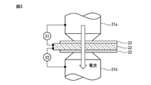
- Fig. 3 shows the method of measuring contact resistance.
- a single steel plate 32 having a zinc-based plating 33 on its surface is sandwiched by an upper electrode 31a and a lower electrode 31b for spot welding.
- a current I of 1 A is applied to the electrodes.
- the voltage V1 between the upper electrode 31a and the steel plate 32 and the voltage V2 between the lower electrode 31b and the steel plate 32 are measured.
- the electrical resistance between the upper electrode 31a and the steel plate 32 is R1
- the electrical resistance between the lower electrode 31b and the steel plate 32 is R3
- the resistance due to the specific resistance of the bulk (base material) of the steel plate 32 is R2.
- R2 can be approximated to zero.
- the resistances of the upper and lower electrodes 31a and 31b can be approximated to zero. Therefore, the relationship between the measured voltages V1 and V2 and the electrical resistances R1 and R3 can be approximated as follows.
- the larger resistance value of R1 and R3 is the contact resistance in the present invention.
- FIG. 3 shows the steel plate 32 having the zinc-based plating 33 formed on both surfaces, a steel plate having the zinc-based plating formed on only one surface may be used in the present invention.
- a nut with a substantially hemispherical projection on the joint surface was used in accordance with JIS B 1196:2010. More specifically, the projection distance (projection height) of three or four (comparative example No. 10 has four projections) projections of 0.90 mm or 1.00 mm in the strength category 8T. A nut was used.
- a pierce hole was formed in a steel plate with a drill, and then the center of the pierce hole and the center of the screw hole of the nut were roughly matched by using a guide pin. In this state, the steel plate and the nut were overlapped with each other, and current was applied to the upper and lower electrodes while applying electric current to perform projection welding.
- a stationary type projection welding machine was used for the projection welding, and after the initial pressurization of 0.5 s, the 0.17 s electrode was held after the preliminary energization process, the cool process and the main energization process under the conditions shown in Table 1. Later, the pressure was released. The pressure applied by the upper and lower electrodes was set to the conditions shown in Table 1 throughout the entire process. For each of the conditions shown in Table 1, projection welding was performed under the same welding conditions to produce 15 test materials.
- an average indentation peel strength of 10.5 kN or more and a Cp of 1.33 or more were defined as “OK”, and those that did not meet this criterion were defined as “NG”.
- the indentation peel strength of the nut can be stably obtained at a high value without variation.
- the average value of the indentation peel strength was the same as that of the manufacturing method of the present invention, but The variation was large, and the judgment of the one-sided process capability index was “NG”.
- Figure 4 shows the fracture surface of the joint after indentation peeling test.
- (A) is the invention example (No. 1)
- (b) is the comparative example (No. 8) in which the pre-energization and the cooling process were not performed.
- each (three) projection joints were fractured substantially evenly, but in (b) there was a difference in fracture state, and it was confirmed that zinc oxide remained in the joints. It was
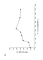
- FIG. 5 shows the relationship between the non-energization time in the cool process and the one-side process capability index. It was confirmed that the one-side process capability index can be increased by setting the non-energization time in the cool process to 70 ms or more.
Landscapes
- Engineering & Computer Science (AREA)
- Mechanical Engineering (AREA)
- Resistance Welding (AREA)
- Heat Treatment Of Articles (AREA)
Abstract
本発明は、安定して高い接合強度を得ることができる、ナット及びボルトの一方又は両方法を有する鋼部材の製造方法を提供する。鋼部材はプロジェクション溶接によって製造され、鋼部材の製造方法は、予備通電工程、70ms以上の無通電時間を有するクール工程、予備通電工程よりも高い電流を流す本通電工程を順に備える。
Description
本発明は鋼部材の製造方法、具体的にはナット及びボルトの一方又は両方を有する鋼部材の製造方法に関する。
近年、特に自動車分野等において、車体の骨格部材で高強度鋼板を熱間プレスしたホットスタンプ材を使用する事例が見られる。また、たとえば、フロントサイドメンバーやセンターピラー、ヒンジリンフォース等の自動車用構造部材においては、ホットスタンプ材からなる部品にナットやボルトが溶接された鋼部材が用いられている。
ナットやボルトが溶接された鋼部材の製造には、プロジェクション溶接法により鋼板の表面にナット又はボルトを接合する方法が一般的である。プロジェクション溶接によって得られる自動車用構造部材には、鋼板とナット、ボルトとの接合強度が高く、かつ、ばらつきが小さいことが求められる。
特許文献1には、溶接部の遅れ破壊特性、静的強度特性に優れた自動車用構造部材として、高強度鋼板とナット又はボルトがプロジェクション溶接によって接合された自動車用構造部材であって、ナット又はボルトのプロジェクションの周囲に局所的に凹部が設けられた構成が開示されている。
特許文献2には、優れた遅れ破壊特性、高い静的強度を得ることが可能な、ナット又はボルトを有する自動車用構造部材として、高強度鋼板とナット又はボルトがプロジェクション溶接によって接合された自動車用構造部材であって、高強度鋼板における熱影響部の板厚方向の深さを所定の範囲とする構成が開示されている。
特許文献3には、ナットまたはボルトの化学成分、ならびに、高強度鋼板の引張強さ、板厚、炭素当量を規定して接合部の硬さと靭性を適度に制御し、さらに、ナットまたはボルトと高強度鋼板との接合部の面積と、ナットまたはボルトの呼び径部分の面積との比を適正範囲で規定することで、トルク剥離強さおよび押込み剥離強さ等の静的強度に優れたプロジェクション溶接継手を製造する方法が開示されている。
例えば自動車用構造部材には、亜鉛系めっき鋼板を熱間プレスしたホットスタンプ材を使用することもある。表面に亜鉛系めっきが形成されたホットスタンプ材にナット又はボルトをプロジェクション溶接で接合する場合は、表面に亜鉛系めっきが形成されていないホットスタンプ材にプロジェクション溶接を行う場合と比べて、接合強度のばらつきが発生しやすくなる。また、自動車用構造部材以外においても、表面に亜鉛系めっきが形成された鋼材にナット又はボルトをプロジェクション溶接で接合する場合は、同様に接合強度のばらつきが発生しやすくなる。ここで、亜鉛系めっきとは、亜鉛を含むめっきを意味する(以下、同じ)。
一定の接合強度を確保するために個別にアーク溶接等の他の接合プロセスを用いると、その分、コスト高となる。その結果、部材によって、高強度鋼板を用いることが阻害される。
本発明は、上記の課題を解決し、亜鉛系めっきを有する鋼材にプロジェクション溶接によりナット、ボルトを接合する場合、安定して高い接合強度(具体的には押込み剥離強度)を得ることができるナット及びボルトの一方又は両方を有する鋼部材の製造方法を提供することを課題とする。
本発明者らは、亜鉛系めっき鋼材にナットやボルトをプロジェクション溶接で接合する場合に、安定して、高い接合強度を得る方法について、鋭意検討した。その結果、接合強度のばらつきの原因となるのは、鋼材表面に存在する高抵抗体である酸化被膜であることが確認できた。
本発明者らは、さらに検討を進め、本発明をなした。その要旨は以下のとおりである。
(1)表面に亜鉛系めっきを有する鋼材と、複数のプロジェクションを備えたナット又はボルトを、加圧しながら通電加熱を行うプロジェクション溶接によって接合する、ナット及びボルトの一方又は両方を有する鋼部材の製造方法であって、予備通電工程、クール工程、及び本通電工程を順に備え、前記予備通電工程では、前記複数のすべてのプロジェクションの高さが予備通電工程の前と比較して0.7~0.9倍となるように通電を行い、前記クール工程は、70ms以上の無通電とする時間を有し、前記本通電工程では、前記予備通電工程よりも高い電流を流すことを特徴とするナット及びボルトの一方又は両方を有する鋼部材の製造方法。
(2)前記クール工程における前記無通電とする時間が400ms以下であることを特徴とする前記(1)のナット及びボルトの一方又は両方を有する鋼部材の製造方法。
(3)前記鋼材の接合前の引張強さが1100MPa以上であることを特徴とする前記(1)又は(2)のナット及びボルトの一方又は両方を有する鋼部材の製造方法。
(4)前記鋼材の常温における接触抵抗が1mΩ以上であることを特徴とする前記(1)~(3)のいずれかのナット及びボルトの一方又は両方を有する鋼部材の製造方法。
本発明によれば、亜鉛系めっきを有する鋼材にプロジェクション溶接によりナット、ボルトを接合する場合であっても、安定して、高い接合強度(具体的には押込み剥離強度)を得ることができる。
はじめに、本発明者らが本発明に至った検討内容について説明する。以下、亜鉛系めっきホットスタンプ材にナットをプロジェクション溶接で接合する場合について説明するが、ボルトを接合する場合であっても同様である。また、亜鉛系めっきホットスタンプ材に限られず、亜鉛系めっきを有する鋼材に接合する場合も同様である。なお鋼材とは、鋼板、および鋼板を成形した成形体等を含む鋼製品を指す。
本発明者らは、亜鉛系めっきホットスタンプ材にプロジェクション溶接によりナットを接合する際に、接合強度にばらつきが生じるのは、鋼板表面に高抵抗体である酸化被膜が存在するためと考えた。より具体的には、以下のとおりである。
特に亜鉛系めっき鋼板を熱間プレスした場合、鋼板の表面には酸化被膜が生じる。酸化被膜は厚さが一定に形成されるのではなく、ある程度の濃淡、つまり厚さのばらつきをもって形成される。たとえば、ナットが複数のプロジェクションを有する場合、各プロジェクションが鋼板に接する位置で酸化被膜の厚さに差があると、酸化被膜は高抵抗体であるから、比較的酸化被膜が薄い位置に接するプロジェクションに電流が流れやすくなり、各プロジェクションに流れる電流の大きさに差が生じる。
図1はこれを模式的に示したものである。なお、図1に示すプロジェクション溶接では、上側電極11aをナット14に接触させ、下側電極11bを鋼板12に接触させ、さらにナット14が有する複数のプロジェクション15を鋼板12に接触させて、上側電極11aから下側電極11bに向けて電流16を流すことで溶接を行う。図1(a)はプロジェクション15から鋼板12に電流が流れる領域での酸化被膜13の厚さが予備通電によって均一化されており、本通電で各プロジェクション15に電流が均一に流れる様子を示す図であり、図1(b)は酸化被膜13に濃淡つまり厚さのばらつきがあり、各プロジェクション15に流れる電流に差がある図である。
図1(b)に示すように、各プロジェクション15に流れる電流16の大きさに差があると、その結果、圧接径に差が生じることとなり、接合強度にばらつきが生じる。すなわち、電流16が集中したプロジェクション15は溶接の初期に潰れ、電流16が流れにくくなったプロジェクション15は溶接の終期までプロジェクションが潰れないので、圧接の条件が各プロジェクション15で異なることとなり、圧接径に差が生じる。なお圧接径とは、プロジェクション溶接の際の電流によって溶融して潰れ鋼板12に接合されたプロジェクション15の、鋼板12との接合面の径を指す。
本発明者らは、これを確認するために、亜鉛系めっき鋼板に熱間プレスを施した亜鉛系めっきホットスタンプ材について、そのままプロジェクション溶接でナットをとりつけた場合と、ショットブラストにより表面の酸化被膜を取り除いた後にプロジェクション溶接でナットをとりつけた場合について、押込み剥離試験により接合強度を比較した。
その結果、ショットブラストにより酸化被膜を取り除いた場合、多数のプロジェクション溶接を行った際に、接合強度のばらつきが小さくなり、接合強度の平均値も大きくなることが確認された。また、観察の結果、ショットブラストを行わずそのままプロジェクション溶接でナットをとりつけた場合は各プロジェクション位置での接合面積(圧接径)が不均一となっていることが確認された。
以上より、亜鉛系めっきホットスタンプ材にプロジェクション溶接により溶接ナットを接合した場合の接合強度のばらつきは、表面の酸化被膜の存在に起因するものであることが確認できた。
ただし、ショットブラストにより酸化被膜を除去する方法は、工程を1つ追加することとなり、コスト高となる問題を解決できないため、本発明者らは、溶接条件を変えることにより、プロジェクション溶接における本通電工程の前に酸化被膜を除去又は薄膜化して、各プロジェクションから電流が流れる領域の酸化被膜の厚さを均一化する方法を検討し、本発明をなしたものである。以下、本発明について説明する。
本発明の鋼部材の製造方法は、表面に亜鉛系めっきを有する鋼材と、複数のプロジェクションを備えたナット又はボルトを、加圧しながら通電加熱を行うプロジェクション溶接によって接合して、ナット及びボルトの一方又は両方を有する鋼部材を製造する方法である。その際、ナット又はボルトをプロジェクション溶接により接合するための通電を行う工程(本通電工程)の前に、予備通電工程として、鋼材とナット又はボルトにおける複数のプロジェクションとを接触させた状態で加圧し、本通電よりも低い電流を流す工程、及びクール工程として通電を行わない工程を設ける。
予備通電工程において、各プロジェクション15と接する鋼板12の酸化被膜13を破壊して除去又は薄膜化する。酸化被膜13は固有抵抗値が高く、分布も一様とは限らないため、予備通電工程で酸化被膜13を破壊して除去又は薄膜化することにより、各プロジェクション15から電流16が流れる領域の酸化被膜13の厚さが均一化され、各プロジェクション15の接触点の電流経路での抵抗がほぼ均一化する。そのため、接合部を形成するための本通電工程では、図1(a)に示すように、各プロジェクション15における電流16の密度が均一となり、各点で均一な接合部が形成可能となる。
本通電での電流密度を均一化するためには、ナットが有する複数のすべてのプロジェクションのプロジェクション高さ(図2参照)が予備通電開始前の0.7~0.9倍となるようにする。複数あるすべてのプロジェクションのプロジェクション高さが予備通電開始前の0.7~0.9倍となるようにするには、予備通電工程での電流の大きさ、通電時間、および加圧力等を調整して行う。
ここで、複数あるすべてのプロジェクションのプロジェクション高さが予備通電開始前の0.7~0.9倍となるよう、予備通電工程を実施する方法について説明する。該方法としては、平板である鋼板を用いて予備通電のみのテスト溶接を行い、予備通電工程の各種条件を予め決定する方法が挙げられる。なお、テスト溶接での予備通電工程の前後でのプロジェクション高さは、平板である鋼板を用いて予備通電のみのテスト溶接を行い、予備通電の前後で、たとえば、ノギスやレーザ式の計測器で測定すればよい。このテスト溶接により、すべてのプロジェクションの高さが予備通電開始前の0.7~0.9倍となる予備通電電流、通電時間、および加圧力を決定し、その予備通電電流、通電時間、および加圧力を用いて、以降のプロジェクション溶接を行えばよい。
予備通電工程の前後のプロジェクション高さは、たとえば、ナット又はボルトが鋼板に接した状態で、それぞれのプロジェクションの位置で、鋼板とプロジェクションを含めたナット又はボルトとの全体の厚さを測定し、この全体の厚さから鋼板の厚さとナット又はボルトのプロジェクションを除いた部分の厚さとを引いた値として求められる。
予備通電後のプロジェクションのプロジェクション高さが予備通電開始前の0.9超~1.0倍の範囲では、予備通電によって、酸化被膜を破壊し、除去又は薄膜化する効果がほとんど得られない。そのため、各プロジェクション(3または4個の場合が多い)位置における電流密度が均一にならない。予備通電後のプロジェクションのプロジェクション高さが予備通電開始前の0.7倍未満となると、プロジェクションの潰れが大きくなりすぎ、本通電工程において必要な電流密度が得られなくなり、適切な溶接が行われなくなる。
予備通電工程の電流値は本通電工程の電流値より低く、たとえば、本通電工程の電流値の1/3~1/5とすることができる。具体的には、予備通電工程においてプロジェクション1つあたりの電流値を1.0~1.4kAとすることができる。予備通電の工程に要する時間は数十ms程度であり、プロジェクション溶接を行う装置で行うので、コストに大きく影響はしない。
予備通電工程と本通電工程の間には、70ms以上無通電とする(つまり通電を行わない)時間である無通電時間を有する工程(クール工程)を設ける。クール工程では電流を0とすれば、加圧した状態は保持したままでよい。クール工程を設けることにより、各プロジェクションの温度が均一化されて、プロジェクション中を流れる電流の流れ易さも均一化される。これにより、本通電で各プロジェクションに流れる電流が均一になり、鋼板とナットの接合強度のばらつきを低減することができ、押込み剥離強度のCp(片側工程能力指数)が上昇する。無通電時間を80ms以上、180ms以上、または200ms以上とするとより効果的である。
クール工程の時間を長くすると特性上のデメリットは少なくない。ただし、予備通電工程から加圧力を一定とする場合、クール工程の時間を長くするとCpが低下し、またプロジェクション高さの減少が進むため、本通電工程での接合部の発熱、および温度上昇が得られにくくなるので、400ms以下、さらには360ms以下とすることが好ましい。
以上のように、予備通電工程において、各プロジェクションと接する鋼板の酸化被膜を破壊して除去又は薄膜化し、且つクール工程で各プロジェクションの温度を均一化することにより、続く本通電工程において、各プロジェクションに電流を均一に流すことが可能となり、鋼板とナットの接合強度が高く、接合強度のばらつきが小さい鋼部材を得ることができる。一般的なプロジェクションを備えたナット又はボルトの場合、プロジェクション溶接前のプロジェクション高さは0.9~1.0mmmmであり、本通電後のプロジェクション高さが0mm近傍となるのが好ましい。
なお、予備通電工程の前の工程、及び本通電工程の後の工程は特に限定しない。一般的なプロジェクション溶接と同様に、圧力のみを加え、電流を流さずに保持する工程があってもよい。
本発明の鋼部材の製造方法に用いる鋼材は、表面に亜鉛系めっきを有する鋼材であれば、特に限定されない。鋼材表面に酸化被膜を生じさせやすいものとして熱間プレスがあげられ、熱間プレスは高強度鋼板に対して適用されることが多いので、特にホットスタンプ材に用いる高強度亜鉛系めっき鋼板に対して好適である。高強度の亜鉛系めっきを有する鋼材としては、たとえば接合前の引張強さが1100MPa以上の亜鉛系めっき鋼材を例示できる。
また、プロジェクション溶接による接合強度のばらつきの発生は、鋼材表面にある高抵抗体の酸化被膜に起因することが多いので、常温における接触抵抗が1mΩ以上である鋼材に好適である。たとえば、亜鉛系めっき鋼板に熱間プレスを施した場合などは酸化被膜を生じやすく、接触抵抗が大きくなりやすいので、本発明に好適である。
接触抵抗の測定方法を図3に示す。表面に亜鉛系めっき33を有する1枚の鋼板32をスポット溶接用の上側電極31aおよび下側電極31bで挟む。電極に1Aの電流Iを通電する。上側電極31aと鋼板32との間の電圧V1、下側電極31bと鋼板32との間の電圧V2を測定する。
上側電極31aと鋼板32間の電気抵抗をR1、下側電極31bと鋼板32間の電気抵抗をR3、鋼板32のバルク(母材)そのものの固有抵抗に起因する抵抗をR2とする。R2はゼロと近似できる。また、上下の電極31a、31bの抵抗もゼロと近似できる。よって、測定された電圧V1、V2と電気抵抗R1、R3との間の関係は次のように近似できる。
V1=(R1+R2)×I≒R1×I=R1×1(A)=R1
V2=(R2+R3)×I≒R3×I=R3×1(A)=R3
V2=(R2+R3)×I≒R3×I=R3×1(A)=R3
R1、R3のいずれか大きいほうの抵抗値を本発明での接触抵抗とする。なお、図3では両面に亜鉛系めっき33が形成された鋼板32を示すが、本発明では片面のみに亜鉛系めっきが形成された鋼板を用いてもよい。
以下、実施例を用いて、本発明をより詳細に説明する。以下の実施例は本発明の実施の態様の一例であり、本発明が以下の態様に限定されるわけではない。
引張強さ1.5GPa、板厚2.3mm、常温における接触抵抗が12mΩ、亜鉛系めっきを両面に有する、ホットスタンプされた鋼板に、表1に示す条件で、プロジェクション溶接により、プロジェクションを有するナットを接合した。
ナットには、JIS B 1196:2010に準拠した、接合面に略半球状のプロジェクションを備えたものを使用した。より具体的には、強度区分8Tで、3個または4個(比較例No.10がプロジェクションが4個の実施例)のプロジェクションの突出距離(プロジェクション高さ)が0.90mm又は1.00mmのナットを用いた。
本実施例では、プロジェクション溶接を行う前に、まず、鋼板にドリルでピアス孔を形成し、その後、ガイドピンを利用してピアス孔の中心と、ナットのねじ孔の中心とをおおむね一致させた状態とし、鋼板とナットとを重ね合わせた状態で、上下の電極で加圧しながら通電加熱を行ってプロジェクション溶接した。
プロジェクション溶接には定置式のプロジェクション溶接機を用い、0.5sの初期加圧の後、表1に記載の条件による予備通電工程、クール工程、本通電工程を経て、0.17s電極を保持した後、圧力を解放した。なお、全工程を通して上下の電極による加圧力を表1に記載の条件とした。表1に記載の各条件について、同じ溶接条件でプロジェクション溶接を行い、15個の供試材を作製した。
予備通電工程後及び本通電工程後のプロジェクション高さは、レーザ変位計で鋼板とプロジェクションを含めたナットとの全体の厚さを測定し、この全体の厚さから鋼板の厚さとナットのプロジェクションを除いた部分の厚さとを引いた値として求めた。表1には、3個または4個ある各プロジェクション高さの15個の平均値を記載した。発明例(No.1~No.7)においては、15個の各プロジェクション高さの予備通電前後での比がすべて、本発明範囲である0.7~0.9に入っていることを確認した。
作製した供試材について、JIS B 1196:2010で規定された押込み剥離試験を行った。この際、鋼板とナットとを接合した供試材における鋼板側から、ピアス孔を通じてボルトをねじ込み、ボルトの頭部から圧縮荷重を付与し、ナットが剥離した際の荷重(押込み剥離強度)を測定した。表1には、15個の供試材の押込み剥離強度の平均値を記載した。また、15個の供試材の押込み剥離強度から、規格下限を10.5kNとしたときの片側工程能力指数(Cp)を求め表1に記載した。なお片側工程能力指数(Cp)とは、対象とする工程がどれだけ均一にばらつきを少なく、且つ求められる性能をもつ製品を作製することができるかを示す指標である。
本実施例では、平均押込み剥離強度10.5kN以上、Cp1.33以上を「OK」とし、この基準を満たさなかったものを「NG」とした。
本発明の鋼部材の製造方法によれば、ナットの押込み剥離強度が、ばらつきなく、高い値で安定して得られることが確認できた。
予備通電、クール工程がない従来方法(No.8)で製造した場合、押込み剥離強度の平均値は、本発明の製造方法と比べ低いものの、判定基準は超える値となった。しかしながら、供試材間のばらつきが大きく、片側工程能力指数の判定は「NG」となった。
予備通電工程を備えるがクール工程がない方法(No.9、10)で製造した場合、押込み剥離強度の平均値は、本発明の製造方法の場合と同等であったが、供試材間のばらつきが大きく、片側工程能力指数の判定は「NG」となった。
予備通電工程を備えるがクール工程がない方法で製造し、予備通電工程におけるプロジェクション高さの変化が小さい場合(No.11)、押込み剥離強度は判定基準を超えるものの低い値となり、供試材間のばらつきが大きく、片側工程能力指数の判定は「NG」となった。
予備通電工程を備えるがクール工程がない方法で製造し、予備通電工程におけるプロジェクション高さを大きく変化させた場合(No.12)、押込み剥離強度は判定基準を超えるものの低い値となり、供試材間のばらつきが大きく、片側工程能力指数の判定は「NG」となった。
予備通電、クール工程を備えるが、予備通電工程においてプロジェクション高さを大きく変化させた場合(No.13)は、押込み剥離強度の平均値は、本発明の製造方法の場合と同等であったが、供試材間のばらつきが大きく、片側工程能力指数の判定は「NG」となった。
予備通電、クール工程を備えるが、クール工程において無通電時間が短い場合(No.14)は、押込み剥離強度の平均値は判定基準を超える値となったものの、供試材間のばらつきが大きく、片側工程能力指数の判定は「NG」となった。
図4に押込み剥離試験後の接合部の破断面を示す。(a)が発明例(No.1)のものであり、(b)が予備通電、クール工程を行わなかった比較例(No.8)のものである。発明例では、各(3個の)プロジェクション接合部がほぼ均等に破断しているが、(b)では破断状態に差があり、また、接合部に酸化亜鉛が残留していることが確認できた。
図5にクール工程での無通電時間と片側工程能力指数の関係を示す。クール工程の無通電時間を70ms以上とすることにより片側工程能力指数を上昇させることができることが確認できた。

11a 上側電極
11b 下側電極
12 鋼板
13 酸化被膜
14 ナット
15 プロジェクション
16 電流
31a 上側電極
31b 下側電極fs
32 鋼板
33 亜鉛系めっき
11b 下側電極
12 鋼板
13 酸化被膜
14 ナット
15 プロジェクション
16 電流
31a 上側電極
31b 下側電極fs
32 鋼板
33 亜鉛系めっき
Claims (4)
- 表面に亜鉛系めっきを有する鋼材と、複数のプロジェクションを備えたナット又はボルトを、加圧しながら通電加熱を行うプロジェクション溶接によって接合する、ナット及びボルトの一方又は両方を有する鋼部材の製造方法であって、
予備通電工程、クール工程、及び本通電工程を順に備え、
前記予備通電工程では、前記複数のすべてのプロジェクションの高さが予備通電工程の前と比較して0.7~0.9倍となるように通電を行い、
前記クール工程は、70ms以上の無通電とする時間を有し、
前記本通電工程では、前記予備通電工程よりも高い電流を流す
ことを特徴とするナット及びボルトの一方又は両方を有する鋼部材の製造方法。 - 前記クール工程における前記無通電とする時間が400ms以下である
ことを特徴とする請求項1に記載のナット及びボルトの一方又は両方を有する鋼部材の製造方法。 - 前記鋼材の接合前の引張強さが1100MPa以上であることを特徴とする請求項1又は2に記載のナット及びボルトの一方又は両方を有する鋼部材の製造方法。
- 前記鋼材の常温における接触抵抗が1mΩ以上であることを特徴とする請求項1~3のいずれか1項に記載のナット及びボルトの一方又は両方を有する鋼部材の製造方法。
Priority Applications (1)
| Application Number | Priority Date | Filing Date | Title |
|---|---|---|---|
| JP2020562530A JP7131634B2 (ja) | 2018-12-27 | 2019-12-27 | 鋼部材の製造方法 |
Applications Claiming Priority (2)
| Application Number | Priority Date | Filing Date | Title |
|---|---|---|---|
| JP2018246055 | 2018-12-27 | ||
| JP2018-246055 | 2018-12-27 |
Publications (1)
| Publication Number | Publication Date |
|---|---|
| WO2020138468A1 true WO2020138468A1 (ja) | 2020-07-02 |
Family
ID=71129152
Family Applications (1)
| Application Number | Title | Priority Date | Filing Date |
|---|---|---|---|
| PCT/JP2019/051543 Ceased WO2020138468A1 (ja) | 2018-12-27 | 2019-12-27 | 鋼部材の製造方法 |
Country Status (2)
| Country | Link |
|---|---|
| JP (1) | JP7131634B2 (ja) |
| WO (1) | WO2020138468A1 (ja) |
Cited By (2)
| Publication number | Priority date | Publication date | Assignee | Title |
|---|---|---|---|---|
| CN112122760A (zh) * | 2020-09-15 | 2020-12-25 | 湖北长平汽车装备有限公司 | 一种防弹钢板与螺母焊接工艺 |
| JP2023143113A (ja) * | 2022-03-25 | 2023-10-06 | 日本製鉄株式会社 | プロジェクション溶接部材の製造方法 |
Citations (3)
| Publication number | Priority date | Publication date | Assignee | Title |
|---|---|---|---|---|
| JPS59699B2 (ja) * | 1974-12-27 | 1984-01-07 | トヨタ自動車株式会社 | コウドホシヨウソウチ |
| JP2005297054A (ja) * | 2004-04-16 | 2005-10-27 | Nippon Steel Corp | プロジェクション溶接方法及びプロジェクション溶接継手並びにプロジェクション溶接構造体 |
| JP2012179646A (ja) * | 2011-03-02 | 2012-09-20 | Nippon Steel Corp | 溶接部の遅れ破壊特性並びに静的強度特性に優れた自動車用構造部材、および、その製造方法 |
Family Cites Families (2)
| Publication number | Priority date | Publication date | Assignee | Title |
|---|---|---|---|---|
| JPH11764A (ja) * | 1997-04-14 | 1999-01-06 | Sekisui Chem Co Ltd | 表面処理鋼材のプロジェクション溶接方法 |
| CN105612020B (zh) | 2013-10-04 | 2018-04-10 | 杰富意钢铁株式会社 | 电阻点焊方法 |
-
2019
- 2019-12-27 JP JP2020562530A patent/JP7131634B2/ja active Active
- 2019-12-27 WO PCT/JP2019/051543 patent/WO2020138468A1/ja not_active Ceased
Patent Citations (3)
| Publication number | Priority date | Publication date | Assignee | Title |
|---|---|---|---|---|
| JPS59699B2 (ja) * | 1974-12-27 | 1984-01-07 | トヨタ自動車株式会社 | コウドホシヨウソウチ |
| JP2005297054A (ja) * | 2004-04-16 | 2005-10-27 | Nippon Steel Corp | プロジェクション溶接方法及びプロジェクション溶接継手並びにプロジェクション溶接構造体 |
| JP2012179646A (ja) * | 2011-03-02 | 2012-09-20 | Nippon Steel Corp | 溶接部の遅れ破壊特性並びに静的強度特性に優れた自動車用構造部材、および、その製造方法 |
Cited By (3)
| Publication number | Priority date | Publication date | Assignee | Title |
|---|---|---|---|---|
| CN112122760A (zh) * | 2020-09-15 | 2020-12-25 | 湖北长平汽车装备有限公司 | 一种防弹钢板与螺母焊接工艺 |
| JP2023143113A (ja) * | 2022-03-25 | 2023-10-06 | 日本製鉄株式会社 | プロジェクション溶接部材の製造方法 |
| JP7840752B2 (ja) | 2022-03-25 | 2026-04-06 | 日本製鉄株式会社 | プロジェクション溶接部材の製造方法 |
Also Published As
| Publication number | Publication date |
|---|---|
| JPWO2020138468A1 (ja) | 2021-09-09 |
| JP7131634B2 (ja) | 2022-09-06 |
Similar Documents
| Publication | Publication Date | Title |
|---|---|---|
| JP5468350B2 (ja) | 異種金属板の接合方法 | |
| CN106413969B (zh) | 用于接合复合板构件与功能元件的方法和装置 | |
| CN114206535B (zh) | 异种材料固相接合方法及异种材料固相接合构造物 | |
| US20090208772A1 (en) | Method of welding three metal sheets and apparatus with three stacked metal sheets | |
| JP2010172946A (ja) | 高強度薄鋼板の抵抗スポット溶接方法 | |
| WO2017069268A1 (ja) | 抵抗スポット溶接方法 | |
| WO2019124464A1 (ja) | 抵抗スポット溶接継手の製造方法 | |
| CN106715026B (zh) | 用于接合复合板构件与另外的构件的方法和装置 | |
| CN115279529A (zh) | 固相点接合方法和固相点接合装置 | |
| JP2012187617A (ja) | 高張力鋼板の接合体、および高張力鋼板の抵抗溶接方法 | |
| WO2015133099A1 (ja) | 抵抗スポット溶接方法 | |
| WO2020138468A1 (ja) | 鋼部材の製造方法 | |
| JP2004050280A (ja) | プロジェクション溶接方法 | |
| JP2018069289A (ja) | 異種金属板の接合方法 | |
| JP2018099713A (ja) | 金属部材と樹脂部材の接合方法 | |
| JP5057557B2 (ja) | シリーズスポット溶接方法及び溶接装置 | |
| JP6589171B2 (ja) | 金属樹脂接合方法及び金属樹脂接合体 | |
| CN109982804A (zh) | 接合结构体及其制造方法 | |
| JP7840752B2 (ja) | プロジェクション溶接部材の製造方法 | |
| JP7529717B2 (ja) | 溶接部材の製造方法 | |
| US11590600B2 (en) | Manufacturing method of joined member | |
| WO2019124465A1 (ja) | 抵抗スポット溶接継手の製造方法 | |
| JP7853635B1 (ja) | スポット溶接継手 | |
| JP2017506583A (ja) | 異種材料の接合方法 | |
| JP2023143121A (ja) | プロジェクション溶接部材の製造方法 |
Legal Events
| Date | Code | Title | Description |
|---|---|---|---|
| 121 | Ep: the epo has been informed by wipo that ep was designated in this application |
Ref document number: 19904235 Country of ref document: EP Kind code of ref document: A1 |
|
| ENP | Entry into the national phase |
Ref document number: 2020562530 Country of ref document: JP Kind code of ref document: A |
|
| NENP | Non-entry into the national phase |
Ref country code: DE |
|
| 122 | Ep: pct application non-entry in european phase |
Ref document number: 19904235 Country of ref document: EP Kind code of ref document: A1 |