WO2020138384A1 - 血液浄化装置 - Google Patents
血液浄化装置 Download PDFInfo
- Publication number
- WO2020138384A1 WO2020138384A1 PCT/JP2019/051340 JP2019051340W WO2020138384A1 WO 2020138384 A1 WO2020138384 A1 WO 2020138384A1 JP 2019051340 W JP2019051340 W JP 2019051340W WO 2020138384 A1 WO2020138384 A1 WO 2020138384A1
- Authority
- WO
- WIPO (PCT)
- Prior art keywords
- pump
- pump tube
- ironing
- locking member
- set position
- Prior art date
Links
Images


Classifications
-
- A—HUMAN NECESSITIES
- A61—MEDICAL OR VETERINARY SCIENCE; HYGIENE
- A61M—DEVICES FOR INTRODUCING MEDIA INTO, OR ONTO, THE BODY; DEVICES FOR TRANSDUCING BODY MEDIA OR FOR TAKING MEDIA FROM THE BODY; DEVICES FOR PRODUCING OR ENDING SLEEP OR STUPOR
- A61M1/00—Suction or pumping devices for medical purposes; Devices for carrying-off, for treatment of, or for carrying-over, body-liquids; Drainage systems
- A61M1/14—Dialysis systems; Artificial kidneys; Blood oxygenators ; Reciprocating systems for treatment of body fluids, e.g. single needle systems for hemofiltration or pheresis
- A61M1/16—Dialysis systems; Artificial kidneys; Blood oxygenators ; Reciprocating systems for treatment of body fluids, e.g. single needle systems for hemofiltration or pheresis with membranes
- A61M1/1601—Control or regulation
-
- A—HUMAN NECESSITIES
- A61—MEDICAL OR VETERINARY SCIENCE; HYGIENE
- A61M—DEVICES FOR INTRODUCING MEDIA INTO, OR ONTO, THE BODY; DEVICES FOR TRANSDUCING BODY MEDIA OR FOR TAKING MEDIA FROM THE BODY; DEVICES FOR PRODUCING OR ENDING SLEEP OR STUPOR
- A61M1/00—Suction or pumping devices for medical purposes; Devices for carrying-off, for treatment of, or for carrying-over, body-liquids; Drainage systems
- A61M1/36—Other treatment of blood in a by-pass of the natural circulatory system, e.g. temperature adaptation, irradiation ; Extra-corporeal blood circuits
- A61M1/3621—Extra-corporeal blood circuits
- A61M1/367—Circuit parts not covered by the preceding subgroups of group A61M1/3621
-
- A—HUMAN NECESSITIES
- A61—MEDICAL OR VETERINARY SCIENCE; HYGIENE
- A61M—DEVICES FOR INTRODUCING MEDIA INTO, OR ONTO, THE BODY; DEVICES FOR TRANSDUCING BODY MEDIA OR FOR TAKING MEDIA FROM THE BODY; DEVICES FOR PRODUCING OR ENDING SLEEP OR STUPOR
- A61M60/00—Blood pumps; Devices for mechanical circulatory actuation; Balloon pumps for circulatory assistance
- A61M60/10—Location thereof with respect to the patient's body
- A61M60/104—Extracorporeal pumps, i.e. the blood being pumped outside the patient's body
- A61M60/109—Extracorporeal pumps, i.e. the blood being pumped outside the patient's body incorporated within extracorporeal blood circuits or systems
- A61M60/113—Extracorporeal pumps, i.e. the blood being pumped outside the patient's body incorporated within extracorporeal blood circuits or systems in other functional devices, e.g. dialysers or heart-lung machines
-
- A—HUMAN NECESSITIES
- A61—MEDICAL OR VETERINARY SCIENCE; HYGIENE
- A61M—DEVICES FOR INTRODUCING MEDIA INTO, OR ONTO, THE BODY; DEVICES FOR TRANSDUCING BODY MEDIA OR FOR TAKING MEDIA FROM THE BODY; DEVICES FOR PRODUCING OR ENDING SLEEP OR STUPOR
- A61M60/00—Blood pumps; Devices for mechanical circulatory actuation; Balloon pumps for circulatory assistance
- A61M60/20—Type thereof
- A61M60/247—Positive displacement blood pumps
- A61M60/253—Positive displacement blood pumps including a displacement member directly acting on the blood
- A61M60/268—Positive displacement blood pumps including a displacement member directly acting on the blood the displacement member being flexible, e.g. membranes, diaphragms or bladders
- A61M60/279—Peristaltic pumps, e.g. roller pumps
-
- A—HUMAN NECESSITIES
- A61—MEDICAL OR VETERINARY SCIENCE; HYGIENE
- A61M—DEVICES FOR INTRODUCING MEDIA INTO, OR ONTO, THE BODY; DEVICES FOR TRANSDUCING BODY MEDIA OR FOR TAKING MEDIA FROM THE BODY; DEVICES FOR PRODUCING OR ENDING SLEEP OR STUPOR
- A61M60/00—Blood pumps; Devices for mechanical circulatory actuation; Balloon pumps for circulatory assistance
- A61M60/30—Medical purposes thereof other than the enhancement of the cardiac output
- A61M60/36—Medical purposes thereof other than the enhancement of the cardiac output for specific blood treatment; for specific therapy
- A61M60/37—Haemodialysis, haemofiltration or diafiltration
-
- A—HUMAN NECESSITIES
- A61—MEDICAL OR VETERINARY SCIENCE; HYGIENE
- A61M—DEVICES FOR INTRODUCING MEDIA INTO, OR ONTO, THE BODY; DEVICES FOR TRANSDUCING BODY MEDIA OR FOR TAKING MEDIA FROM THE BODY; DEVICES FOR PRODUCING OR ENDING SLEEP OR STUPOR
- A61M60/00—Blood pumps; Devices for mechanical circulatory actuation; Balloon pumps for circulatory assistance
- A61M60/40—Details relating to driving
- A61M60/424—Details relating to driving for positive displacement blood pumps
- A61M60/457—Details relating to driving for positive displacement blood pumps the force acting on the blood contacting member being magnetic
- A61M60/462—Electromagnetic force
-
- A—HUMAN NECESSITIES
- A61—MEDICAL OR VETERINARY SCIENCE; HYGIENE
- A61M—DEVICES FOR INTRODUCING MEDIA INTO, OR ONTO, THE BODY; DEVICES FOR TRANSDUCING BODY MEDIA OR FOR TAKING MEDIA FROM THE BODY; DEVICES FOR PRODUCING OR ENDING SLEEP OR STUPOR
- A61M60/00—Blood pumps; Devices for mechanical circulatory actuation; Balloon pumps for circulatory assistance
- A61M60/80—Constructional details other than related to driving
- A61M60/835—Constructional details other than related to driving of positive displacement blood pumps
-
- A—HUMAN NECESSITIES
- A61—MEDICAL OR VETERINARY SCIENCE; HYGIENE
- A61M—DEVICES FOR INTRODUCING MEDIA INTO, OR ONTO, THE BODY; DEVICES FOR TRANSDUCING BODY MEDIA OR FOR TAKING MEDIA FROM THE BODY; DEVICES FOR PRODUCING OR ENDING SLEEP OR STUPOR
- A61M2205/00—General characteristics of the apparatus
- A61M2205/14—Detection of the presence or absence of a tube, a connector or a container in an apparatus
-
- A—HUMAN NECESSITIES
- A61—MEDICAL OR VETERINARY SCIENCE; HYGIENE
- A61M—DEVICES FOR INTRODUCING MEDIA INTO, OR ONTO, THE BODY; DEVICES FOR TRANSDUCING BODY MEDIA OR FOR TAKING MEDIA FROM THE BODY; DEVICES FOR PRODUCING OR ENDING SLEEP OR STUPOR
- A61M2205/00—General characteristics of the apparatus
- A61M2205/60—General characteristics of the apparatus with identification means
- A61M2205/6018—General characteristics of the apparatus with identification means providing set-up signals for the apparatus configuration
Definitions
- the present invention relates to a blood purification device having an ironing pump.
- a blood purification apparatus for performing dialysis treatment is for purifying blood that circulates extracorporeally in the blood circuit and an arterial blood circuit and a venous blood circuit that form a blood circuit for circulating the patient's blood extracorporeally.
- Blood purifier, and various therapeutic devices such as blood pumps for blood purification treatment with the blood circuit and blood purifier, and the patient was punctured with the arterial puncture needle and the venous puncture needle. After that, by driving the blood pump, the blood of the patient flows through the arterial blood circuit and the venous blood circuit, and the blood is purified by the blood purifier during the flowing process.
- Patent Document 1 discloses an attachment member that has a plurality of pump tubes that can be attached to an ironing pump provided in a blood purification device and that is attached to a predetermined position of the blood purification device.
- the present invention has been made in view of the above circumstances, and can improve workability when attaching a pump tube to an ironing pump or workability when removing a pump tube from an ironing pump. To provide.
- a stator to which a pump tube including a first portion and a second portion is detachably attached, a roller for handling the pump tube attached to the stator and feeding the liquid, and the pump tube. And a rotor for rotating around a predetermined axis, and a locking member for locking the mounting member to which the pump tube is mounted.
- a displacement portion that displaces the mounting member locked by the locking member between a set position and a non-set position by moving the locking member, the guide of the ironing pump By moving the locking member from the non-setting position to the setting position in a state where the portion is stopped at a specific phase, the first portion of the pump tube is in an attachable state in which the first portion is arranged in the proper position, By driving the ironing type pump in the mountable state to rotate the rotor by a predetermined angle, the guide portion winds the pump tube into the stator, and the first portion and the second portion of the pump tube. Loading is performed in which the part is placed in the proper position.
- the invention according to claim 2 is an ironing pump having a roller mounted on the stator for handling and feeding the pump tube, and a rotor having a guide portion for holding the pump tube at an appropriate position where the pump tube can be handled.
- a locking member that locks the mounting member to which the pump tube is mounted, and the mounting member that moves the locking member and is locked by the locking member between a set position and a non-set position.
- the ironing type pump is driven to rotate the rotor by a predetermined angle so that the guide portion causes the pump tube to move. Is pushed out of the stator to perform unloading with the first and second portions of the pump tube in the improper position.
- the rotor is stopped while the guide portion is in the specific phase, and the rotor is rotated by a predetermined angle to perform the loading or the loading.
- a control unit for executing unloading is provided.
- a plurality of the ironing pumps are arranged and the mounting member is an arrangement of the ironing pumps.
- the pump member has a number of pump tubes according to the number of units, and the locking member moves between the set position and the non-set position to load or unload the plurality of pump tubes.
- the displacement member is operated to move the locking member so that the mounting member is not in the set position.
- the operation unit is provided with a displacement function between the set position and the operation position, and the operation unit has an auxiliary function of assisting the operation force.
- a sixth aspect of the present invention is the blood purification apparatus according to any one of the first to fifth aspects, further comprising a detection unit that detects that the pump tube is in the attachable state or the detachable state. To do.
- the mounting member has pump tubes corresponding to the number of the plurality of ironing type pumps arranged, and the detection unit includes: The pump tube that is not in the attachable state or the detachable state is detected, and the ironing pump that is the attachment target is specified.
- the detection unit is in the mountable state or the detachable state of the pump tube that is loaded or unloaded on the adjacent ironing pumps, respectively. To detect.
- the locking member moves from the non-set position to the set position while the guide portion of the ironing pump is stopped at a specific phase, whereby the first portion of the pump tube is moved to the proper position.
- the guide portion winds the pump tube into the stator and the first portion of the pump tube and the pump tube. Since the loading is performed with the second portion of the pump set to the proper position, the workability when mounting the pump tube on the ironing pump can be improved.
- the first portion of the pump tube is dislocated from the proper position.
- the improper position is set to the removable state and the iron pump is driven in the removable state to rotate the rotor by a predetermined angle
- the guide portion pushes the pump tube out of the stator, and the first portion of the pump tube is moved. Since the unloading is performed by setting the portion and the second portion to the improper positions, the workability when removing the pump tube from the ironing pump can be improved.
- the control portion is provided to perform loading or unloading. It is possible to further improve the workability in mounting the pump or the workability in removing the pump tube from the ironing pump.
- a plurality of the ironing type pumps are arranged, the mounting member has pump tubes corresponding to the number of the ironing type pumps, and the locking member is different from the set position. Since the plurality of pump tubes are moved to and from the set position to load or unload the plurality of pump tubes, the plurality of pump tubes can be collectively loaded or unloaded, and the working time can be shortened.
- the operating section includes an operating section that operates the displacing section to move the locking member and displaces the mounting member between the set position and the non-set position. Since it has the auxiliary function of assisting the force, it is possible to improve the operability of the operation portion and smoothly move the locking member and the displacement of the mounting member.
- the pump tube since the pump tube is provided with the detection unit that detects whether the pump tube is in the attachable state or the detachable state, it is possible to grasp the state in which the loading or unloading cannot be appropriately performed. You can
- the mounting member has pump tubes corresponding to the number of the plurality of ironing type pumps arranged, and the detection portion is a pump tube which is not in the mountable state or the detachable state. Is detected and the ironing pump to be attached is specified, it is possible to identify the ironing pump that cannot be properly loaded or unloaded among the plurality of ironing pumps.
- the detector detects the mountable state or the detachable state of the pump tubes to be loaded or unloaded on the adjacent ironing type pumps respectively.
- the number of installations can be reduced, and the manufacturing cost can be reduced.
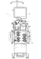
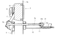
- FIG. 1 is a member showing a member to which an attachment member is attached in the blood purification device, wherein (a) is a perspective view seen from the front side and (b) is a perspective view seen from the back side.
- FIG. 1 is a member showing a member to which an attachment member is attached in the blood purification device, wherein (a) is a perspective view seen from the front side and (b) is a perspective view seen from the back side.
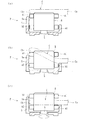
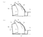
- FIG. 4 is a schematic view showing a process of attaching a pump tube to an ironing pump of the blood purifying apparatus, in which (a) a state before movement of a locking member (b) state after movement of a locking member (before loading ( c) Diagram showing the state after loading It is a schematic diagram which shows the process which removes a pump tube from the ironing type pump of the same blood purification
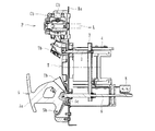
- FIG. 9 Schematic diagram showing a state in which the attachment member is in the set position in the blood purification device
- Sectional view taken along line ⁇ 1- ⁇ 1 in FIG. 9 is a sectional view taken along line ⁇ 2- ⁇ 2 in FIG.
- It is a schematic diagram which shows the locking member of the blood purification apparatus, Comprising: (a) The state which locked the mounting member (b) The figure which shows the state which displaces a mounting member from a set position to a non-set position.
- the blood purification apparatus 1 includes a monitor M capable of displaying information related to blood purification treatment, and a hemodialysis treatment monitoring apparatus having a blood pump N and the like.
- a monitor M capable of displaying information related to blood purification treatment
- a hemodialysis treatment monitoring apparatus having a blood pump N and the like.
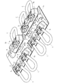
- the blood purification apparatus 1 includes a plurality of (7 in the present embodiment) ironing pumps P on the front side so that replacement fluid and drainage fluid can be delivered during blood purification treatment. Has become.
- the blood purification apparatus 1 is configured so that a mounting member T can be mounted as shown in FIGS.
- the mounting member T holds a pump tube C that can be squeezed in a predetermined direction by the ironing type pump P to feed a liquid.
- the mounting member T can be mounted at a predetermined position Ba of the blood purification device 1. It has a portion Ta and a holding portion Tb attached to the body portion Ta and holding the pump tube C.
- the mounting member T is made of a resin molded product in which the main body portion Ta and the holding portion Tb are integrally formed, and the bending portion formed along the boundary line between the main body portion Ta and the holding portion Tb is bent to form the main body.
- the holding portion Tb is three-dimensionally attached to the front side of the portion Ta. It should be noted that the bent portion is formed with perforations and the like, so that the holding portion Tb can be easily bent with respect to the main body portion Ta.
- the holding portion Tb is made of a resin-molded portion that is protrudingly molded (bulged toward the front side) in a block shape with respect to the main body portion Ta, and the connectors D formed at both ends of the pump tube C are fitted into the holding portion Tb. It has a holding groove that can be fixed at a predetermined height. That is, by fitting and fixing the connector D in the holding groove, the pump tube C is held in the holding portion Tb as shown in FIG. Further, as shown in the figure, the holding portion Tb has a locking hole Tc formed at a predetermined portion, and can be locked by a locking member 2 included in the blood purification device 1.
- the pump tube C is formed of a soft resin or a rubber material having a flow path of a relatively large diameter, and extends from the base end portion Ca (first portion) to the tip end portion Cb (second portion).
- the connector D is formed in a loop shape and the base end portion Ca is formed. Then, after the pump tube C is attached to a predetermined position (appropriate position that can be handled by the roller Ra) in the stator S of the ironing type pump P, when the rotor R is driven to rotate, it is handled by the roller Ra in the longitudinal direction, Liquids such as replacement fluid and drainage fluid can be sent.
- the holding portion Tb according to the present embodiment is attached on the inclined surface formed on the main body portion Ta, the pump tube C has a predetermined size with respect to the bottom surface of the main body portion Ta (the attachment surface for the predetermined position Ba). It is arranged to be extended at an angle (inclined along an inclined surface). That is, the holding portion Tb according to the present embodiment holds the connector D of the pump tube C in an inclined state, and holds the pump tube C while inclining the pump tube C toward the mounting direction of the pump tube C with respect to the ironing type pump P. Is configured to.
- the main body Ta according to the present embodiment is configured such that a tube (not shown) constituting a liquid flow path connected to the connector D of the pump tube C is arranged in the central portion thereof. That is, the central portion of the main body Ta according to the present embodiment has a concave shape that opens to the back side, and the tube connected to the connector D of the pump tube C is arranged along the concave shape. It is configured.
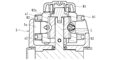
- the ironing type pump P can handle the pump tube C in a certain direction to feed a liquid, and as shown in FIGS. 3 and 4, a stator S having a mounting recess Sa and a stator S provided in the mounting recess Sa.
- a rotor R rotatable about a rotation axis L (an imaginary line of rotation passing through the inside of the rotation axis L), a roller Ra attached to the rotor R, and guide pins (upper guide pins a1, b1 and lower guide pin a2, b2) (guide portion).
- the rotor R has a pair of upper and lower upper guide pins a1 and lower guide pins a2 protruding from the stator S, and a pair of upper and lower upper guide pins b1 and lower guide pins b2.
- the pump tube C is attached between the lower guide pin a2 and between the upper guide pin b1 and the lower guide pin b2.
- the upper guide pins a1 and b1 are located on the opening side of the mounting recess Sa
- the lower guide pins a2 and b2 are located on the bottom side of the mounting recess Sa, and are mounted in the mounting recess Sa of the stator S.
- the pump tube C thus held is held at a proper position (a proper position that can be handled by the roller Ra), and is prevented from coming off the proper position.
- the attachment member T can be attached to a predetermined position Ba on the front side where the ironing pump P is arranged.
- a positioning pin g is formed, and the positioning pin g is formed on the main body portion Ta of the mounting member T.
- the attachment member T can be positioned at a predetermined position Ba of the blood purification device 1 by inserting it into the positioning hole h.
- a plurality of locking members 2 (7 in the present embodiment) are attached to the predetermined position Ba of the blood purification device 1 according to the present embodiment, and the holding portion Tb is provided.
- the locking member 2 has a locking claw 2a formed on one side of the projecting end and a pressing portion 2b formed on the other side, and the locking claw 2a is opened in the locking hole Tc.
- the mounting member T is locked to the locking member 2 by being locked to the edge portion (see FIG. 15A) so as to be mounted at the predetermined position Ba.
- the displacement part 3 moves the locking member 2 and locks the mounting member T locked by the locking member 2 at a set position (positions shown in FIGS. 8, 10, 12) and a non-set position (FIGS. 9, 11, 13). (The position shown by) and is movable while being guided by the guide portion 4. Specifically, as shown in FIG. 5B, the guide portion 4 is fixed to the back side of the member in which the predetermined position Ba is formed, and a frame-shaped displacement portion that can be fitted into the guide portion 4. 3 is slidably mounted.
- an interlocking member 6 connected to the operation unit 5 and an interlocking member 7 connected to the locking member 2 are attached to the displacement unit 3, respectively.
- the displacement portion 3 moves (moves in the left-right direction in the figure) while being guided by the guide portion 4, and the locking member 2 can be moved along with the movement.
- the mounting member T can be set to the non-set position, and The mounting member T can be set to the set position by sliding the displacement portion 3 by operation and moving the locking member 2 to a position close to the predetermined position Ba.
- the detection switch 8 is fixed, and when the operation unit 5 is operated to move the interlocking member 6, its operation position is changed.
- the detection switch 8 is configured to detect. This makes it possible to detect that the operation unit 5 has been operated.
- the guide unit 4 according to the present embodiment is provided with a control unit 11 (see FIG. 16) for controlling the driving of the ironing pump P, a control circuit for performing various controls, and the like. K is attached.
- the operation part 5 operates the displacement part 3 to move the locking member 2 to displace the attachment member T between the set position and the non-set position, and assists the operation force. It has an auxiliary function. That is, as shown in FIGS. 10 and 11, the operating section 5 includes a gripping section 5 a that is gripped and operated by an operator, a swing center section 5 b that configures a swing axis of the operating section 5, and an interlocking member 6. It is configured to have a connecting portion 5c that is connected, and swings around the swing center portion 5b by operating the grip portion 5a, and together with the interlocking member 6, the displacement portion 3 and the locking portion are locked by the lever principle.
- the member 2 is movable, and has an auxiliary function (a so-called booster mechanism) that utilizes the "lever principle".
- the auxiliary function for assisting the operating force may be another function such as a link.
- the mounting member T is positioned by the positioning pin g, and the locking hole Tc is locked by the locking claw 2a of the locking member 2 (FIG. 15A). 5), the mounting member T is set to the non-set position, and as shown in FIG. 5A, the pump tube C held by the holding portion Tb has the proximal end Ca and the distal end Cb squeezed. It is located above the upper guide pins a1 and b1 in the mold pump P (inappropriate position deviating from the proper position).
- each ironing type pump P is in a state where the guide pins (a1, a2, b1, b2) (guide portion) are stopped at a specific phase (see FIGS. 2 and 3), and the pump tube C As shown by the chain double-dashed line in FIG. 10, the tip end portion Cb is in contact with the upper portion of the upper guide pin a1 (inappropriate position).
- the mounting member T is displaced in the direction of approaching the predetermined position Ba, and the mounting member T moves from the non-set position to the set position (Fig. 11 (see 11).
- the base end portion Ca of the pump tube C is positioned at an appropriate position between the upper guide pin b1 and the lower guide pin b2, as shown in FIG. 5(b).
- the tip end portion Cb of the pump tube C is located at an improper position above the upper guide pin a1 and becomes ready for attachment.
- the tip portion Cb of the pump tube C is kept in contact with the upper portion of the upper guide pin a1 (inappropriate position) as shown by the solid line in FIG.
- the operating portion 5 is operated to move the locking member 2.
- the mounting member T is displaced in the direction away from the predetermined position Ba, and the mounting member T is displaced from the set position to the non-set position (see FIG. 10).
- the tip portion Cb of the pump tube C is positioned between the upper guide pin b1 and the lower guide pin b2 as shown in FIG.
- each ironing type pump P is in a state where the guide pins (a1, a2, b1, b2) (guide portion) are stopped at a specific phase (see FIGS. 2 and 3).
- the control unit 11 is composed of a microcomputer or the like attached to the control board K, stops the rotor R in a state where the guide pins (a1, a2, b1, b2) (guide unit) are in a specific phase, and keeps the rotor R at a predetermined position. It is configured to perform the loading or unloading by rotating by an angle.
- the control unit 11 may be realized by appropriately combining an arithmetic element such as a CPU, a memory, a storage device, software, and an interface.
- the blood purification device 1 includes the detection unit 9 that detects whether the pump tube C is in the attachable state or the detachable state.
- the detection unit 9 is composed of a rod-shaped member that can come into contact with a predetermined portion in the holding portion Tb of the mounting member T mounted at the predetermined position Ba, and is biased toward the protruding side by the spring 9a. Has been done.
- the detecting portion 9 follows the mounting member T and moves against the biasing force of the spring 9a.
- the spring 9a is assembled such that one end of the spring 9a abuts on the support frame f1 fixed to the blood purification apparatus 1 and the other end abuts on the detection unit 9.
- a stopper 10b is attached to the base end side of the detection unit 9, and a resistor 10a is fixed by a support frame f2 near the base end side.
- the resistor 10a and the stopper 10b constitute the potentiometer 10.
- the resistor 10 causes the resistor 10 to move or move the stopper 10b (that is, the detector 9). It is possible to output by converting into a voltage according to the movement amount and position of the.
- the pump tube C does not reach the set position due to interference with the components of the ironing type pump P and the mountable state.
- the movement amount of the detection unit 9 is different from the regular movement amount.
- the detection unit 9 detects the pump tube C that is not in the attachable state, the ironing pump P that is the attachment target can be specified.
- the pump tube C interferes with the components of the ironing type pump P and the like and the non-set position does not occur.
- the movement amount of the detection unit 9 is different from the regular movement amount.
- the detection unit 9 detects the pump tube C that is not in the removable state, the ironing pump P that is the attachment target thereof can be specified.
- the detection unit 9 when the detection unit 9 detects the pump tube C that is not in the attachable state or the detachable state and the ironing pump P that is the attachment target is specified, the identified ironing pump P is used.
- the pump P can be displayed on the monitor M to notify the user. As a result, the operator can easily and accurately grasp that the mountable state or the detachable state is not established even though the operating section 5 has been operated.
- the detection unit 9 is arranged between two locking members 2 as shown in FIG. 2, and is a pump that is loaded or unloaded on each of the adjacent ironing pumps P.
- a single detector 9 can detect whether the tube C can be attached or detached. That is, it is possible to detect that one or both of the two adjacent ironing type pumps P are not in the attachable state or the detachable state by the one detection unit 9 (in the present embodiment, FIG.
- the detection unit 9 on the right side of is capable of detecting that any one or all of the three adjacent ironing pumps P are not in the attachable state or the detachable state.
- the potentiometer 10 detects the movement amount (position) of the detection unit 9, either one (either one) is adjacent depending on the detected movement amount or position. It is possible to make a distinction between the case where is not the attachable state or the detachable state and the case where both (all) are not the attachable state or the detachable state. In this case, the mountable state or the detachable state does not occur, and the iron pump P can be specified more accurately, and the subsequent measures can be more appropriately and smoothly performed.
- the rotor R to which the roller Ra is attached has the cap portion R1 and the frame portion R2, and the cap portion R1 is smaller than the frame portion R2. Has been formed. Further, the corner R2a of the frame R2 is chamfered. This can prevent the pump tube C from being caught by the cap portion R1 or the frame portion R2 during loading or unloading.
- a treatment device for is constructed.
- Such a treatment device includes a blood circuit U having a dialyzer Q, a first dialysate introduction line L1a and a second dialysate introduction line L1b for introducing a dialysate into the dialyzer Q, and a first replacement fluid for supplying a replacement fluid to the blood circuit U.
- a line L2a, a second replacement liquid line L2b, a front replacement liquid line L2c and a rear replacement liquid line L2d, and a first drainage discharge line L3a and a second drainage discharge line L3b for discharging the drainage of the dialyzer Q are configured. ing.
- the blood circuit U is configured to have an arterial blood circuit Ua and a venous blood circuit Ub, and the blood pump N is driven by puncturing the patient with the tips of the arterial blood circuit Ua and the venous blood circuit Ub. By doing so, the blood of the patient can be extracorporeally circulated.
- the dialyzer Q is provided with a blood introducing port Qa, a blood deriving port Qb, a dialysate introducing port Qc and a dialysate deriving port Qd formed on the housing thereof, and the blood introducing port Qa of the dialyzer Q has an arterial side.
- the blood circuit Ua is connected to the blood outlet port Qb and the vein side blood circuit Ub is connected to the dialysate inlet port Qc, and the second dialysate inlet line L1b is connected to the dialysate outlet port Qd.
- the discharge lines L3a are connected to each other.
- the first dialysate introduction line L1a is connected to the dialysate storage bag W1 that stores the dialysate, and is also connected to the second dialysate introduction line L1b via the subdivision chamber Y. Then, when the ironing pump P provided in the first dialysate introduction line L1a and the second dialysate introduction line L1b is driven, the dialysate in the dialysate storage bag W1 is subdivided in the subdivision chamber Y. , Is introduced into the dialyzer Q.
- the first replacement fluid line L2a is connected to the replacement fluid storage bag W2 that stores the replacement fluid, and is also connected to the second replacement fluid line L2b via the subdivision chamber Y.
- the second replacement fluid line L2b is connected to the blood circuit U via a front replacement fluid line L2c connected to the arterial blood circuit Ua and a rear replacement fluid line L2d connected to the vein side blood circuit Ub.
- a check valve V1 is connected to the rear replacement fluid line L2d.
- the first drainage discharge line L3a is connected to the dialyzer Q, and is also connected to the second drainage discharge line L3b via the subdivision chamber Y.
- the second drainage discharge line L3b can drain the drainage to the outside of the apparatus. Then, when the ironing type pump P disposed in the first drainage discharge line L3a and the second drainage discharge line L3b is driven, the drainage in the dialyzer Q is subdivided in the subdivision chamber Y, and then the device It can be discharged to the outside.
- the pump tube C of the mounting member T is connected to the flow path (the first replacement fluid introduction line L2a, the second replacement fluid introduction line L2b, and the previous replacement fluid line L2c) for introducing the replacement fluid into the blood circuit U, and the blood circuit U.
- a flow path (first dialysate introduction line L1a and second dialysate introduction line L1b) for introducing dialysate to the connected dialyzer Q (blood purifier), and drainage of the dialyzer Q (blood purifier).
- the flow paths (first drainage discharge line L3a and second drainage discharge line L3b) are connected to each other.
- the pump tube C of the mounting member T may be connected to the rear replacement fluid line L2d.
- the pump tube C of the attachment member T is not attached to the blood pump N, but the pump tube C of the attachment member T may be loaded and attached to the blood pump N. ..
- the blood circuit U is connected to the pump tube C of the mounting member T. That is, the mounting member T according to the present invention can be loaded into the pump tube C, the blood circuit U for circulating blood extracorporeally, the flow path for introducing the replacement fluid into the blood circuit U (first replacement fluid line L2a, second replacement fluid line L2a).
- pre-replacement fluid line L2c (or post-replenishment fluid line L2d), and a flow path (first dialysate introduction line L1a and second dialysate) for introducing dialysate into the dialyzer Q (blood purifier) connected to the blood circuit U.
- a blood purification circuit including an introduction line L1b) or a flow path (first drainage discharge line L3a and second drainage discharge line L3b) that discharges drainage of a dialyzer Q (blood cleaner).
- the locking member 2 moves from the non-set position to the set position in a state where the guide pins (a1, a2, b1, b2) (guide portion) of the ironing pump P are stopped at a specific phase
- the proximal end portion Ca of the pump tube C is set to an appropriate position to be in a mountable state, and in the mountable state, the ironing type pump P is driven to rotate the rotor R by a predetermined angle, so that the guide pins (a1, a2, b1). , B2) winds the pump tube C into the stator S and performs loading such that the proximal end Ca and the distal end Cb of the pump tube P are in proper positions. Therefore, when the pump tube C is attached to the ironing pump P, The workability of can be improved.
- the base of the pump tube C is The end portion Ca is in the improper position deviating from the proper position to be in the removable state, and in the detachable state, the ironing type pump P is driven to rotate the rotor R by a predetermined angle, whereby the guide pin (a1, a2, b1, b2) pushes the pump tube C out of the stator S to perform unloading in which the proximal end portion Ca and the distal end portion Cb of the pump tube C are in the improper position, so that the pump tube is removed from the ironing pump P. Workability when removing C can be improved.
- the rotor R is stopped with the guide pins (a1, a2, b1, b2) (guide portions) in a specific phase, and the rotor R is rotated by a predetermined angle to perform loading or unloading. Therefore, the workability in attaching the pump tube C to the ironing pump P or the workability in removing the pump tube C from the ironing pump P can be further improved.
- a plurality of ironing type pumps P according to the present embodiment are arranged, the mounting member T has pump tubes C according to the number of the ironing type pumps P, and the locking member 2 is provided. Since the plurality of pump tubes C are loaded or unloaded by moving between the set position and the non-set position, the plurality of pump tubes C can be collectively loaded or unloaded, and the working time can be shortened. You can
- the operating section 5 is provided which operates the displacement section 3 to move the locking member 2 to displace the attachment member T between the set position and the non-set position, and the operation section 5 applies an operating force. Since the auxiliary function is provided, the operability of the operation portion 5 can be improved and the movement of the locking member 2 and the displacement of the mounting member T can be smoothly performed. Further, since the pump tube C is provided with the detection unit 9 that detects that the pump tube C is in the attachable state or the detachable state, it is possible to grasp the state in which the loading or unloading cannot be appropriately performed.
- the mounting member T has pump tubes C corresponding to the number of arranged ironing pumps P, and the detection unit 9 is in a mountable state or a detachable state. Since the undesired pump tube C is detected and the ironing pump P to which it is attached is specified, the ironing pump P that cannot be properly loaded or unloaded among the plurality of ironing pumps P is grasped. be able to.
- the detection unit 9 detects the mountable state or the detachable state of the pump tube C loaded or unloaded on the adjacent ironing type pumps P, so that the required detection unit 9 is required. Can be reduced, and the manufacturing cost can be reduced.
- the present invention is not limited to this, and, for example, a plurality of or a single squeezing pump P provided in the blood purification device 1 other than 7, and a pump tube C is provided.
- the ironing type pumps P may be held by the holding unit Tb in the number corresponding to the number.
- the displacement portion 3 is manually operated by the operation portion 5 to move the locking member 2.
- the displacement portion 3 is operated by an actuator such as a motor or a cylinder, and the locking member 2 is moved. May be moved.
- the first part of the pump tube is placed in an appropriate position and is ready for mounting.
- the guide portion winds the pump tube into the stator, and the first portion and the second portion of the pump tube are arranged at proper positions. As long as the blood purifying device executes the loading, the device having other functions may be added.
Landscapes
- Health & Medical Sciences (AREA)
- Heart & Thoracic Surgery (AREA)
- Engineering & Computer Science (AREA)
- Cardiology (AREA)
- General Health & Medical Sciences (AREA)
- Public Health (AREA)
- Biomedical Technology (AREA)
- Hematology (AREA)
- Life Sciences & Earth Sciences (AREA)
- Animal Behavior & Ethology (AREA)
- Veterinary Medicine (AREA)
- Anesthesiology (AREA)
- Mechanical Engineering (AREA)
- Urology & Nephrology (AREA)
- Vascular Medicine (AREA)
- Physics & Mathematics (AREA)
- Electromagnetism (AREA)
- Pulmonology (AREA)
- Emergency Medicine (AREA)
- External Artificial Organs (AREA)
Abstract
本発明は、第1の部分及び第2の部分を含むポンプチューブが着脱可能に装着されるステータと、当該ステータに装着されたポンプチューブを扱いて送液するローラ及び当該ポンプチューブを前記ローラで扱き得る適正位置に保持するガイド部が形成されると共に所定軸線周りに回転するロータと、を有するしごき型ポンプと、前記ポンプチューブが取り付けられた取付部材を係止する係止部材と、前記係止部材を移動させることによって、当該係止部材が係止した前記取付部材をセット位置と非セット位置との間で変位させる変位部と、を具備し、前記しごき型ポンプの前記ガイド部が特定位相で停止した状態で前記係止部材が前記非セット位置から前記セット位置に移動することによって、前記ポンプチューブの前記第1の部分が前記適正位置に配置される取付可能状態となり、当該取付可能状態で前記しごき型ポンプを駆動して前記ロータを所定角度回転させることにより、前記ガイド部が前記ポンプチューブを前記ステータ内に巻き込んで当該ポンプチューブの前記第1の部分及び第2の部分が前記適正位置に配置されるローディングが実行される血液浄化装置である。
Description
本発明は、しごき型ポンプを有する血液浄化装置に関するものである。
一般に、透析治療を行うための血液浄化装置は、患者の血液を体外循環させるための血液回路を構成する動脈側血液回路及び静脈側血液回路と、血液回路にて体外循環する血液を浄化するための血液浄化器と、血液回路及び血液浄化器にて血液浄化治療させるための血液ポンプ等の種々の治療器具が取り付けられている、そして、動脈側穿刺針及び静脈側穿刺針を患者に穿刺した後、血液ポンプを駆動させることにより、患者の血液が動脈側血液回路及び静脈側血液回路を流動することとなり、その流動過程において血液浄化器にて血液浄化されるようになっている。
また、血液浄化装置は、補液や排液等を送液するための複数のしごき型ポンプを有するものがあり、これらしごき型ポンプにそれぞれポンプチューブを取り付けることにより、種々液体を送液可能とされたものが提案されている。従来、例えば特許文献1には、血液浄化装置に配設されたしごき型ポンプにそれぞれ取り付け可能なポンプチューブを複数有するとともに、血液浄化装置の所定位置に取り付けられる取付部材について開示されている。
しかしながら、上記従来の血液浄化装置においては、しごき型ポンプにポンプチューブを取り付ける際、作業者がロータを回転させつつステータ内にポンプチューブを送り込んで挿入する必要があるため、取付時の作業性が悪いという不具合がある。また、しごき型ポンプからポンプチューブを取り外す際、作業者がロータを回転させつつステータ内のポンプチューブを取り外す必要があるため、取り外し時の作業性が悪いという不具合がある。
本発明は、このような事情に鑑みてなされたもので、しごき型ポンプにポンプチューブを取り付ける際の作業性又はしごき型ポンプからポンプチューブを取り外す際の作業性を向上させることができる血液浄化装置を提供することにある。
請求項1記載の発明は、第1の部分及び第2の部分を含むポンプチューブが着脱可能に装着されるステータと、当該ステータに装着されたポンプチューブを扱いて送液するローラ及び当該ポンプチューブを前記ローラで扱き得る適正位置に保持するガイド部が形成されると共に所定軸線周りに回転するロータと、を有するしごき型ポンプと、前記ポンプチューブが取り付けられた取付部材を係止する係止部材と、前記係止部材を移動させることによって、当該係止部材が係止した前記取付部材をセット位置と非セット位置との間で変位させる変位部とを具備し、前記しごき型ポンプの前記ガイド部が特定位相で停止した状態で前記係止部材が前記非セット位置から前記セット位置に移動することによって、前記ポンプチューブの前記第1の部分が前記適正位置に配置される取付可能状態となり、当該取付可能状態で前記しごき型ポンプを駆動して前記ロータを所定角度回転させることにより、前記ガイド部が前記ポンプチューブを前記ステータ内に巻き込んで当該ポンプチューブの前記第1の部分及び第2の部分が前記適正位置に配置されるローディングが実行される。
請求項2記載の発明は、ステータに取り付けられたポンプチューブを扱いて送液するローラ、及び当該ポンプチューブを前記ローラで扱き得る適正位置に保持するガイド部が形成されたロータを有するしごき型ポンプと、前記ポンプチューブが取り付けられた取付部材を係止する係止部材と、前記係止部材を移動させて当該係止部材で係止した前記取付部材をセット位置と非セット位置との間で変位させる変位部とを具備し、前記しごき型ポンプの前記ガイド部が特定位相で停止した状態で前記係止部材が前記セット位置から前記非セット位置に移動すると、前記ポンプチューブの第1の部分が前記適正位置から外れた非適正位置とされて取外可能状態となり、当該取外可能状態で前記しごき型ポンプを駆動して前記ロータを所定角度回転させることにより、前記ガイド部が前記ポンプチューブを前記ステータから押し出して当該ポンプチューブの第1の部分及び第2の部分を前記非適正位置とするアンローディングが実行される。
請求項3記載の発明は、請求項1又は請求項2記載の血液浄化装置において、前記ガイド部が前記特定位相にある状態で前記ロータを停止させるとともに、前記ロータを所定角度回転さて前記ローディング又はアンローディングを実行させる制御部を具備する。
請求項4記載の発明は、請求項1~3の何れか1つに記載の血液浄化装置において、前記しごき型ポンプは、複数配設されるとともに、前記取付部材は、当該しごき型ポンプの配設数に応じたポンプチューブを有し、前記係止部材が前記セット位置と非セット位置との間で移動して複数の前記ポンプチューブを前記ローディング又はアンローディングする。
請求項5記載の発明は、請求項1~4の何れか1つに記載の血液浄化装置において、前記変位部を操作して前記係止部材を移動させ、前記取付部材を前記セット位置と非セット位置との間で変位させる操作部を具備するとともに、当該操作部は、操作力を補助する補助機能を有する。
請求項6記載の発明は、請求項1~5の何れか1つに記載の血液浄化装置において、前記ポンプチューブが前記取付可能状態又は取外可能状態となったことを検知する検知部を具備する。
請求項7記載の発明は、請求項6記載の血液浄化装置において、前記取付部材は、複数配設された前記しごき型ポンプの配設数に応じたポンプチューブを有するとともに、前記検知部は、前記取付可能状態又は取外可能状態とならないポンプチューブを検知して、その取付対象である前記しごき型ポンプを特定する。
請求項8記載の発明は、請求項7記載の血液浄化装置において、前記検知部は、隣合う前記しごき型ポンプにそれぞれローディング又はアンローディングされる前記ポンプチューブの前記取付可能状態又は取外可能状態を検知する。
請求項1の発明によれば、しごき型ポンプのガイド部が特定位相で停止した状態で係止部材が非セット位置からセット位置に移動することによって、ポンプチューブの第1の部分が適正位置にある取付可能状態となり、当該取付可能状態でしごき型ポンプを駆動してロータを所定角度回転させることにより、ガイド部がポンプチューブをステータ内に巻き込んで当該ポンプチューブの第1の部分及び当該ポンプチューブの第2の部分を適正位置とするローディングが実行されるので、しごき型ポンプにポンプチューブを取り付ける際の作業性を向上させることができる。
請求項2の発明によれば、しごき型ポンプのガイド部が特定位相で停止した状態で係止部材がセット位置から非セット位置に移動すると、ポンプチューブの第1の部分が適正位置から外れた非適正位置とされて取外可能状態となり、当該取外可能状態でしごき型ポンプを駆動してロータを所定角度回転させることにより、ガイド部がポンプチューブをステータから押し出して当該ポンプチューブの第1の部分及び第2の部分を非適正位置とするアンローディングが実行されるので、しごき型ポンプからポンプチューブを取り外す際の作業性を向上させることができる。
請求項3の発明によれば、ガイド部が特定位相にある状態でロータを停止させるとともに、ロータを所定角度回転さてローディング又はアンローディングを実行させる制御部を具備するので、しごき型ポンプにポンプチューブを取り付ける際の作業性又はしごき型ポンプからポンプチューブを取り外す際の作業性をより一層向上させることができる。
請求項4の発明によれば、しごき型ポンプは、複数配設されるとともに、取付部材は、当該しごき型ポンプの配設数に応じたポンプチューブを有し、係止部材がセット位置と非セット位置との間で移動して複数のポンプチューブをローディング又はアンローディングするので、複数のポンプチューブを一括してローディング又はアンローディングさせることができ、作業時間を短縮させることができる。
請求項5の発明によれば、変位部を操作して係止部材を移動させ、取付部材をセット位置と非セット位置との間で変位させる操作部を具備するとともに、当該操作部は、操作力を補助する補助機能を有するので、操作部の操作性を向上させて係止部材の移動及び取付部材の変位を円滑に行わせることができる。
請求項6の発明によれば、ポンプチューブが取付可能状態又は取外可能状態となったことを検知する検知部を具備するので、ローディング又はアンローディングを適切に行うことができない状態を把握させることができる。
請求項7の発明によれば、取付部材は、複数配設されたしごき型ポンプの配設数に応じたポンプチューブを有するとともに、検知部は、取付可能状態又は取外可能状態とならないポンプチューブを検知して、その取付対象であるしごき型ポンプを特定するので、複数のしごき型ポンプのうち、ローディング又はアンローディングを適切に行うことができないしごき型ポンプを把握させることができる。
請求項8の発明によれば、検知部は、隣合うしごき型ポンプにそれぞれローディング又はアンローディングされるポンプチューブの取付可能状態又は取外可能状態を検知するので、必要とされる検知部の配設数を低減させることができ、製造コストを削減させることができる。
以下、本発明の実施形態について図面を参照しながら具体的に説明する。
本実施形態に係る血液浄化装置1は、図1、2に示すように、血液浄化治療に関わる情報等が表示可能なモニタMと、血液ポンプN等を有する血液透析治療の監視装置から成り、血液ポンプNを駆動させることにより血液回路にて患者の血液を体外循環させつつ血液浄化器(ダイアライザQ)にて血液浄化治療を行うよう構成されている。本実施形態に係る血液浄化装置1は、正面側に複数(本実施形態においては7個)のしごき型ポンプPを具備しており、血液浄化治療時に補液や排液を送液し得るようになっている。
本実施形態に係る血液浄化装置1は、図1、2に示すように、血液浄化治療に関わる情報等が表示可能なモニタMと、血液ポンプN等を有する血液透析治療の監視装置から成り、血液ポンプNを駆動させることにより血液回路にて患者の血液を体外循環させつつ血液浄化器(ダイアライザQ)にて血液浄化治療を行うよう構成されている。本実施形態に係る血液浄化装置1は、正面側に複数(本実施形態においては7個)のしごき型ポンプPを具備しており、血液浄化治療時に補液や排液を送液し得るようになっている。
また、本実施形態に係る血液浄化装置1には、図1、5に示すように、取付部材Tが取り付けられるよう構成されている。かかる取付部材Tは、しごき型ポンプPによって所定方向にしごかれて送液可能なポンプチューブCを保持したもので、図14に示すように、血液浄化装置1の所定位置Baに取り付け可能な本体部Taと、本体部Taに取り付けられ、ポンプチューブCを保持する保持部Tbとを具備している。
かかる取付部材Tは、本体部Ta及び保持部Tbが一体的に形成された樹脂成形品から成り、本体部Ta及び保持部Tbの境界線に沿って形成された折り曲げ部を折り曲げることにより、本体部Taの正面側に保持部Tbが立体的に取り付けられた状態とされている。なお、折り曲げ部は、ミシン目等が形成されており、本体部Taに対する保持部Tbの折り曲げが容易とされている。
保持部Tbは、本体部Taに対してブロック状に突出成形(正面側に膨出して成形)された樹脂成形部から成り、ポンプチューブCの両端に形成されたコネクタDをそれぞれ嵌合して所定高さで固定可能な保持溝を有している。すなわち、保持溝にコネクタDを嵌合して固定することにより、図14に示すように、ポンプチューブCが保持部Tbに保持されるようになっている。また、保持部Tbは、同図に示すように、所定の部位に係止孔Tcが形成されており、血液浄化装置1が具備する係止部材2にて係止可能とされている。
ポンプチューブCは、比較的大きな径の流路を有する軟質樹脂又はゴム材等で形成されたもので、基端部Ca(第1の部分)から先端部Cb(第2の部分)に亘ってループ状に形成されるとともに、基端部CaにコネクタDがそれぞれ形成されている。そして、ポンプチューブCがしごき型ポンプPのステータS内の所定位置(ローラRaで扱き得る適正位置)に取り付けられた後、ロータRを回転駆動させると、ローラRaにて長手方向に扱かれ、補液や排液等の液体を送液し得るようになっている。
しかるに、本実施形態に係る保持部Tbは、本体部Taに形成された傾斜面上に取り付けられているため、ポンプチューブCが本体部Taの底面(所定位置Baに対する取り付け面)に対して所定角度傾斜(傾斜面に沿って傾斜)して延設されるようになっている。すなわち、本実施形態に係る保持部Tbは、ポンプチューブCのコネクタDを傾斜した状態で保持しており、しごき型ポンプPに対するポンプチューブCの取付方向に向かってポンプチューブCを傾斜させつつ保持するよう構成されている。
さらに、本実施形態に係る本体部Taは、その中央部にポンプチューブCのコネクタDに接続された液体の流路を構成するチューブ(不図示)が配設されるよう構成されている。すなわち、本実施形態に係る本体部Taの中央部は、背面側に開口した凹形状とされており、その凹形状に沿ってポンプチューブCのコネクタDに接続されたチューブが配設されるよう構成されている。
しごき型ポンプPは、ポンプチューブCを一定方向に扱いて液体を送液し得るもので、図3、4に示すように、取付凹部Saを有するステータSと、取付凹部Sa内に配設されて回転軸L(回転軸Lの内部を通る回転仮想線)を中心に回転可能なロータRと、ロータRに取り付けられたローラRa及びガイドピン(上ガイドピンa1、b1及び下ガイドピンa2、b2)(ガイド部)とを有して構成されている。そして、ステータSの取付凹部Sa内にポンプチューブCを取り付けてロータRを所定軸線周りに回転駆動させると、取付凹部Saの壁面とローラRaとの間でポンプチューブCが扱かれて送液可能とされている。
また、ロータRは、ステータSから突出形成された上下一対の上ガイドピンa1及び下ガイドピンa2、並びに上下一対の上ガイドピンb1及び下ガイドピンb2を有しており、上ガイドピンa1及び下ガイドピンa2の間、及び上ガイドピンb1及び下ガイドピンb2の間にポンプチューブCが取り付けられるようになっている。なお、上ガイドピンa1、b1は、取付凹部Saの開口側に位置するとともに、下ガイドピンa2、b2は、取付凹部Saの底面側に位置しており、ステータSの取付凹部Sa内に取り付けられたポンプチューブCが適正位置(ローラRaで扱き得る適正位置)に保持し、適正位置から外れてしまうのを抑制している。
本実施形態に係る血液浄化装置1は、しごき型ポンプPが配設された正面側の所定位置Baに取付部材Tが取り付け可能とされている。具体的には、本実施形態に係る血液浄化装置1は、図1、2に示すように、位置決めピンgが形成されており、その位置決めピンgを取付部材Tの本体部Taに形成された位置決め孔hに挿通させることにより、血液浄化装置1の所定位置Baに取付部材Tを位置決め可能とされている。
さらに、本実施形態に係る血液浄化装置1の所定位置Baには、図2に示すように、複数の係止部材2(本実施形態においては7個)が取り付けられているとともに、保持部Tbは、既述のように、係止部材2に係止可能な係止孔Tcを有している。かかる係止部材2は、図15に示すように、その突端部の一方側に係止爪2a及び他方側に押圧部2bがそれぞれ形成されており、係止爪2aを係止孔Tcの開口縁部に係止(図15(a)参照)させることにより取付部材Tが係止部材2に係止されて所定位置Baに取り付けられるようになっている。
変位部3は、係止部材2を移動させて当該係止部材2で係止した取付部材Tをセット位置(図8、10、12で示す位置)と非セット位置(図9、11、13で示す位置)との間で変位させるもので、案内部4にて案内されつつ移動可能とされている。具体的には、図5(b)に示すように、所定位置Baが形成された部材の背面側に案内部4が固定されるとともに、この案内部4に嵌合し得る枠状の変位部3が摺動可能に取り付けられている。
かかる変位部3には、図10、11に示すように、操作部5に連結された連動部材6と、係止部材2に連結された連動部材7とがそれぞれ取り付けられており、操作部5を操作することによって、変位部3が案内部4にて案内されつつ移動(同図中左右方向に移動)するとともに、その移動に伴って係止部材2を移動可能とされている。しかして、係止部材2が所定位置Baに対して離間した位置にて係止爪2aに取付部材Tを係止させることにより取付部材Tを非セット位置とすることができ、変位部3の操作によって変位部3を摺動させて係止部材2を所定位置Baに対して近接した位置まで移動させることにより取付部材Tをセット位置とすることができる。
さらに、本実施形態に係る血液浄化装置1には、図10、11に示すように、検知スイッチ8が固定されており、操作部5を操作して連動部材6が移動すると、その操作位置を検知スイッチ8が検知し得るよう構成されている。これにより、操作部5の操作が行われたことを検知可能とされている。なお、本実施形態に係る案内部4には、しごき型ポンプPの駆動を制御するための制御部11(図16参照)や種々の制御を行わせるための制御回路等が形成された制御基板Kが取り付けられている。
操作部5は、既述のように、変位部3を操作して係止部材2を移動させ、取付部材Tをセット位置と非セット位置との間で変位させるもので、操作力を補助する補助機能を有している。すなわち、操作部5は、図10、11に示すように、操作者が把持して操作する把持部5aと、操作部5の揺動軸を構成する揺動中心部5bと、連動部材6に連結された連結部5cとを有して構成されており、把持部5aを操作することにより揺動中心部5bを中心に揺動し、てこの原理で連動部材6と共に変位部3及び係止部材2を移動可能とされており、かかる「てこの原理」を利用した補助機能(所謂、倍力機構)を有しているのである。なお、操作力を補助する補助機能は、リンク等、他の機能であってもよい。
ここで、本実施形態に係る血液浄化装置1は、取付部材Tが位置決めピンgにて位置決めされつつ係止孔Tcが係止部材2の係止爪2aにて係止(図15(a)参照)されると、取付部材Tが非セット位置とされ、図5(a)に示すように、保持部Tbで保持されたポンプチューブCは、その基端部Ca及び先端部Cbが各しごき型ポンプPにおける上ガイドピンa1、b1より上部(適正位置から外れた非適正位置)に位置することとなる。このとき、各しごき型ポンプPのロータRは、ガイドピン(a1、a2、b1、b2)(ガイド部)が特定位相(図2、3参照)で停止した状態とされており、ポンプチューブCの先端部Cbは、図10中の二点鎖線で示すように、上ガイドピンa1の上部に当接した状態(非適正位置)とされている。
かかる状態において、操作部5を操作して係止部材2を移動させることにより、取付部材Tが所定位置Baに近接する方向に変位することとなり、取付部材Tが非セット位置からセット位置(図11参照)に変位する。このように、取付部材Tがセット位置に変位すると、図5(b)に示すように、ポンプチューブCの基端部Caが上ガイドピンb1と下ガイドピンb2の間の適正位置に位置し、且つ、当該ポンプチューブCの先端部Cbが上ガイドピンa1の上部の非適正位置に位置して取付可能状態となる。なお、取付可能状態においては、ポンプチューブCの先端部Cbは、図11中の実線で示すように、上ガイドピンa1の上部に当接した状態(非適正位置)が維持される。
そして、このような取付可能状態からしごき型ポンプPを駆動させてロータRを所定角度(180~360度程度)回転駆動させることにより、図5(c)に示すように、ポンプチューブCの基端部Caが上ガイドピンb1と下ガイドピンb2の間の適正位置に位置しつつ、ポンプチューブCの先端部Cbが上ガイドピンb1に干渉してステータS内に巻き込まれ、上ガイドピンa1と下ガイドピンa2の間の適正位置に位置することとなる。しかして、ポンプチューブCの基端部Ca及び先端部Cbが適正位置となるので、ポンプチューブCがしごき型ポンプPに対してローディングされることとなる。このように、適正位置にポンプチューブCが巻き込まれてセット状態とする取り付け作業をローディングという。なお、セット状態においては、ポンプチューブCの先端部Cbは、図11中の二点鎖線で示すように、上ガイドピンb1と下ガイドピンb2の間の適正位置とされている。
一方、取付部材Tを取り外すには、図6(a)に示すように、ポンプチューブCがしごき型ポンプPにセットされたセット状態において、操作部5を操作して係止部材2を移動させることにより、取付部材Tが所定位置Baから離間する方向に変位することとなり、取付部材Tがセット位置から非セット位置(図10参照)に変位する。このように、取付部材Tが非セット位置に変位すると、図6(b)に示すように、ポンプチューブCの先端部Cbが上ガイドピンb1と下ガイドピンb2の間の適正位置(図10中の実線参照)に位置し、且つ、当該ポンプチューブCの基端部Caが上ガイドピンa1の上部の非適正位置に位置して取外可能状態となる。このとき、各しごき型ポンプPのロータRは、ガイドピン(a1、a2、b1、b2)(ガイド部)が特定位相(図2、3参照)で停止した状態とされている。
そして、このような取外可能状態からしごき型ポンプPを駆動させてロータRを所定角度(180~360度程度)回転駆動させることにより、図6(c)に示すように、ポンプチューブCの基端部Caが上ガイドピンb1の上部の非適正位置に位置しつつ、ポンプチューブCの先端部Cbが上ガイドピンb1に干渉してステータSから押し出され、上ガイドピンa1の上部の非適正位置に位置することとなる。しかして、ポンプチューブCの基端部Ca及び先端部Cbが非適正位置となるので、ポンプチューブCがしごき型ポンプPに対してアンローディングされることとなる。このように、非適正位置にポンプチューブCが押し出されてセット状態が解除される取り外し作業をアンローディングという。なお、アンセット状態においては、ポンプチューブCの先端部Cbは、図10中の二点鎖線で示すように、上ガイドピンb1の上部の非適正位置とされている。
制御部11は、制御基板Kに取り付けられたマイコン等から成り、ガイドピン(a1、a2、b1、b2)(ガイド部)が特定位相にある状態でロータRを停止させるとともに、ロータRを所定角度回転さてローディング又はアンローディングを実行させるよう構成されている。制御部11は、CPU等の演算素子、メモリ、記憶装置、ソフトウェア、インターフェイスを適宜組み合わせて実現されるものであってもよい。
さらに、本実施形態に係る血液浄化装置1は、ポンプチューブCが取付可能状態又は取外可能状態となったことを検知する検知部9を具備している。かかる検知部9は、図12に示すように、所定位置Baに取り付けられた取付部材Tにおける保持部Tb内の所定部位と当接可能な棒状部材から成り、スプリング9aによって突出する側に付勢されている。そして、取付部材Tが非セット位置からセット位置に変位すると、その取付部材Tに追従して検知部9がスプリング9aの付勢力に抗して移動するよう構成されている。なお、スプリング9aは、その一端が血液浄化装置1に固定された支持フレームf1と当接し、他端が検知部9に当接して組み付けられている。
また、検知部9の基端側には、ストッパ10bが取り付けられるとともに、その基端側近傍には、抵抗体10aが支持フレームf2にて固定されている。これら抵抗体10a及びストッパ10bは、ポテンショメータ10を構成するもので、検知部9が移動してストッパ10bを移動させると、抵抗体10によって、そのストッパ10bの移動量や位置(すなわち、検知部9の移動量や位置)に応じた電圧に変換して出力可能とされている。
これにより、操作部5を操作して取付部材Tを非セット位置からセット位置とする場合、例えばポンプチューブCがしごき型ポンプPの構成部品等に干渉してセット位置とならず、取付可能状態に至らないとき、ポテンショメータ10にて出力された電圧に基づいて、検知部9の移動量が正規の移動量と異なることを検知することができる。また、本実施形態においては、検知部9にて取付可能状態とならないポンプチューブCを検知すると、その取付対象であるしごき型ポンプPを特定し得るよう構成されている。
同様に、操作部5を操作して取付部材Tをセット位置から非セット位置とする場合、例えばポンプチューブCがしごき型ポンプPの構成部品等に干渉して非セット位置とならず、取外可能状態に至らないとき、ポテンショメータ10にて出力された電圧に基づいて、検知部9の移動量が正規の移動量と異なることを検知することができる。また、本実施形態においては、検知部9にて取外可能状態とならないポンプチューブCを検知すると、その取付対象であるしごき型ポンプPを特定し得るよう構成されている。
さらに、本実施形態においては、検知部9が取付可能状態又は取外可能状態とならないポンプチューブCを検知して、その取付対象であるしごき型ポンプPが特定されると、その特定されたしごきポンプPを例えばモニタMに表示して報知し得るようになっている。これにより、操作部5を操作したにも関わらず、取付可能状態又は取外可能状態とならないことを操作者に容易且つ正確に把握させることができる。
またさらに、本実施形態に係る検知部9は、図2に示すように、2つの係止部材2の間に配設されており、隣合うしごき型ポンプPにそれぞれローディング又はアンローディングされるポンプチューブCの取付可能状態又は取外可能状態を単一の検知部9にて検知可能とされている。すなわち、一つの検知部9によって、2つの隣り合うしごき型ポンプPのうち何れか一方或いは両方が取付可能状態又は取外状態とならないことを検知することができる(本実施形態においては、図2の右側の検知部9は、3つの隣り合うしごき型ポンプPのうち何れか一つ或いは全部が取付可能状態又は取外状態とならないことを検知可能)のである。
なお、本実施形態においては、ポテンショメータ10にて検知部9の移動量(位置)を検知しているので、その検知される移動量や位置に応じて隣り合う何れか一方(何れか一つ)が取付可能状態又は取外状態とならない場合と、両方(全部)が取付可能状態又は取外状態とならない場合とで判別させることができる。この場合、取付可能状態又は取外状態とならないしごき型ポンプPをより正確に特定することができ、その後の対処をより適切且つ円滑に行わせることができる。
また、本実施形態に係るしごき型ポンプPは、図4に示すように、ローラRaが取り付けられたロータRは、キャップ部R1及びフレーム部R2を有するとともに、キャップ部R1がフレーム部R2より小さく形成されている。また、フレーム部R2の角部R2aは、面取り加工されている。これにより、ローディング又はアンローディング時にポンプチューブCがキャップ部R1やフレーム部R2に引っ掛かってしまうのを抑制することができる。
本実施形態において、取付部材Tが血液浄化装置1の所定位置Baに係止され、ポンプチューブCが複数のしごき型ポンプPにそれぞれローディングされると、図16に示すように、血液浄化治療のための治療装置が構築される。かかる治療装置は、ダイアライザQを有する血液回路Uと、ダイアライザQに透析液を導入する第1透析液導入ラインL1a及び第2透析液導入ラインL1bと、血液回路Uに補液を供給する第1補液ラインL2a、第2補液ラインL2b、前補液ラインL2c及び後補液ラインL2dと、ダイアライザQの排液を排出する第1排液排出ラインL3a及び第2排液排出ラインL3bとを有して構成されている。
血液回路Uは、動脈側血液回路Ua及び静脈側血液回路Ubを有して構成されており、これら動脈側血液回路Ua及び静脈側血液回路Ubの先端を患者に穿刺して血液ポンプNを駆動させることにより、患者の血液を体外循環可能とするものである。また、ダイアライザQは、その筐体部に、血液導入ポートQa、血液導出ポートQb、透析液導入ポートQc及び透析液導出ポートQdが突出形成されており、このうち血液導入ポートQaには動脈側血液回路Uaが、血液導出ポートQbには静脈側血液回路Ubがそれぞれ接続されるとともに、透析液導入ポートQcには第2透析液導入ラインL1bが、透析液導出ポートQdには第1排液排出ラインL3aがそれぞれ接続されるようになっている。
第1透析液導入ラインL1aは、透析液を収容する透析液収容バッグW1に接続されるとともに、小分けチャンバYを介して第2透析液導入ラインL1bと接続されている。そして、第1透析液導入ラインL1a及び第2透析液導入ラインL1bに配設されたしごき型ポンプPを駆動させると、透析液収容バッグW1内の透析液が小分けチャンバYにて小分けされた後、ダイアライザQに導入されるようになっている。
第1補液ラインL2aは、補液を収容する補液収容バッグW2に接続されるとともに、小分けチャンバYを介して第2補液ラインL2bと接続されている。かかる第2補液ラインL2bは、動脈側血液回路Uaに接続された前補液ラインL2c及び静脈側血液回路Ubに接続された後補液ラインL2dを介して血液回路Uと接続されている。なお、後補液ラインL2dには、逆止弁V1が接続されている。そして、第1補液ラインL2a及び第2補液ラインL2bに配設されたしごき型ポンプPを駆動させると、補液収容バッグW2内の補液が小分けチャンバYにて小分けされた後、前補液ラインL2cに配設されたしごき型ポンプPの駆動状態に応じて、動脈側血液回路Ua又は静脈側血液回路Ubに導入されるようになっている。
第1排液排出ラインL3aは、ダイアライザQに接続されるとともに、小分けチャンバYを介して第2排液排出ラインL3bと接続されている。かかる第2排液排出ラインL3bは、排液を装置の外部に排出可能とされている。そして、第1排液排出ラインL3a及び第2排液排出ラインL3bに配設されたしごき型ポンプPを駆動させると、ダイアライザQ内の排液が小分けチャンバYにて小分けされた後、装置の外部に排出可能とされている。
このように、取付部材TのポンプチューブCには、血液回路Uに補液を導入する流路(第1補液導入ラインL2a、第2補液導入ラインL2b及び前補液ラインL2c)と、血液回路Uに接続されたダイアライザQ(血液浄化器)に透析液を導入する流路(第1透析液導入ラインL1a及び第2透析液導入ラインL1b)と、当該ダイアライザQ(血液浄化器)の排液を排出する流路(第1排液排出ラインL3a及び第2排液排出ラインL3b)がそれぞれ接続されている。なお、後補液ラインL2dに取付部材TのポンプチューブCを接続させるようにしてもよい。
また、本実施形態においては、血液ポンプNには、取付部材TのポンプチューブCが取り付けられていないが、かかる血液ポンプNに取付部材TのポンプチューブCをローディングして取り付けるようにしてもよい。この場合、取付部材TのポンプチューブCに血液回路Uが接続されることとなる。すなわち、本発明に係る取付部材TのポンプチューブCにローディング可能なものとして、血液を体外循環させる血液回路U、血液回路Uに補液を導入する流路(第1補液ラインL2a、第2補液ラインL2b、前補液ラインL2c(若しくは後補液ラインL2d))、血液回路Uに接続されたダイアライザQ(血液浄化器)に透析液を導入する流路(第1透析液導入ラインL1a及び第2透析液導入ラインL1b)、又はダイアライザQ(血液浄化器)の排液を排出する流路(第1排液排出ラインL3a及び第2排液排出ラインL3b)から成る血液浄化用回路が挙げられる。
上記実施形態によれば、しごき型ポンプPのガイドピン(a1、a2、b1、b2)(ガイド部)が特定位相で停止した状態で係止部材2が非セット位置からセット位置に移動すると、ポンプチューブCの基端部Caが適正位置とされて取付可能状態となり、当該取付可能状態でしごき型ポンプPを駆動してロータRを所定角度回転させることにより、ガイドピン(a1、a2、b1、b2)がポンプチューブCをステータS内に巻き込んで当該ポンプチューブPの基端部Ca及び先端部Cbを適正位置とするローディングが実行されるので、しごき型ポンプPにポンプチューブCを取り付ける際の作業性を向上させることができる。
また、しごき型ポンプPのガイドピン(a1、a2、b1、b2)(ガイド部)が特定位相で停止した状態で係止部材2がセット位置から非セット位置に移動すると、ポンプチューブCの基端部Caが適正位置から外れた非適正位置とされて取外可能状態となり、当該取外可能状態でしごき型ポンプPを駆動してロータRを所定角度回転させることにより、ガイドピン(a1、a2、b1、b2)がポンプチューブCをステータSから押し出して当該ポンプチューブCの基端部Ca及び先端部Cbを非適正位置とするアンローディングが実行されるので、しごき型ポンプPからポンプチューブCを取り外す際の作業性を向上させることができる。
さらに、ガイドピン(a1、a2、b1、b2)(ガイド部)が特定位相にある状態でロータRを停止させるとともに、ロータRを所定角度回転さてローディング又はアンローディングを実行させる制御部11を具備するので、しごき型ポンプPにポンプチューブCを取り付ける際の作業性又はしごき型ポンプPからポンプチューブCを取り外す際の作業性をより一層向上させることができる。
またさらに、本実施形態に係るしごき型ポンプPは、複数配設されるとともに、取付部材Tは、当該しごき型ポンプPの配設数に応じたポンプチューブCを有し、係止部材2がセット位置と非セット位置との間で移動して複数のポンプチューブCをローディング又はアンローディングするので、複数のポンプチューブCを一括してローディング又はアンローディングさせることができ、作業時間を短縮させることができる。
また、変位部3を操作して係止部材2を移動させ、取付部材Tをセット位置と非セット位置との間で変位させる操作部5を具備するとともに、当該操作部5は、操作力を補助する補助機能を有するので、操作部5の操作性を向上させて係止部材2の移動及び取付部材Tの変位を円滑に行わせることができる。さらに、ポンプチューブCが取付可能状態又は取外可能状態となったことを検知する検知部9を具備するので、ローディング又はアンローディングを適切に行うことができない状態を把握させることができる。
またさらに、本実施形態に係る取付部材Tは、複数配設されたしごき型ポンプPの配設数に応じたポンプチューブCを有するとともに、検知部9は、取付可能状態又は取外可能状態とならないポンプチューブCを検知して、その取付対象であるしごき型ポンプPを特定するので、複数のしごき型ポンプPのうち、ローディング又はアンローディングを適切に行うことができないしごき型ポンプPを把握させることができる。特に、本実施形態に係る検知部9は、隣合うしごき型ポンプPにそれぞれローディング又はアンローディングされるポンプチューブCの取付可能状態又は取外可能状態を検知するので、必要とされる検知部9の配設数を低減させることができ、製造コストを削減させることができる。
以上、本実施形態について説明したが、本発明はこれに限定されず、例えば血液浄化装置1に配設されたしごき型ポンプPが7個以外の複数、或いは単数配設され、ポンプチューブCが当該しごき型ポンプPの個数に対応する数だけ保持部Tbに保持されたものであってもよい。また、本実施形態においては、操作部5により変位部3を手動操作して係止部材2を移動させているが、モータやシリンダ等のアクチュエータにて変位部3を操作して係止部材2を移動させるものであってもよい。
しごき型ポンプのガイド部が特定位相で停止した状態で係止部材が非セット位置からセット位置に移動することによって、ポンプチューブの第1の部分が適正位置に配置される取付可能状態となり、当該取付可能状態でしごき型ポンプを駆動してロータを所定角度回転させることにより、ガイド部がポンプチューブをステータ内に巻き込んで当該ポンプチューブの第1の部分及び第2の部分が適正位置に配置されるローディングが実行される血液浄化装置であれば、他の機能が付加されたもの等であってもよい。
1 血液浄化装置
2 係止部材
2a 係止爪
2b 押圧部
3 変位部
4 案内部
5 操作部
5a 把持部
5b 揺動中心部
5c 連結部
6 連動部材
7 連動部材
8 検知スイッチ
9 検知部
10 ポテンショメータ
11 制御部
M モニタ
T 取付部材
Ta 本体部
Tb 保持部
Tc 係止孔
D コネクタ
C ポンプチューブ
P しごき型ポンプ
S ステータ
Sa 取付凹部
R ロータ
R1 キャップ部
R2 フレーム部
Ra ローラ
a1、a2、b1、b2 ガイドピン(ガイド部)
L 回転軸
g 位置決めピン
h 位置決め孔
Ba 所定位置
2 係止部材
2a 係止爪
2b 押圧部
3 変位部
4 案内部
5 操作部
5a 把持部
5b 揺動中心部
5c 連結部
6 連動部材
7 連動部材
8 検知スイッチ
9 検知部
10 ポテンショメータ
11 制御部
M モニタ
T 取付部材
Ta 本体部
Tb 保持部
Tc 係止孔
D コネクタ
C ポンプチューブ
P しごき型ポンプ
S ステータ
Sa 取付凹部
R ロータ
R1 キャップ部
R2 フレーム部
Ra ローラ
a1、a2、b1、b2 ガイドピン(ガイド部)
L 回転軸
g 位置決めピン
h 位置決め孔
Ba 所定位置
Claims (8)
- 第1の部分及び第2の部分を含むポンプチューブが着脱可能に装着されるステータと、当該ステータに装着されたポンプチューブを扱いて送液するローラ及び当該ポンプチューブを前記ローラで扱き得る適正位置に保持するガイド部が形成されると共に所定軸線周りに回転するロータと、を有するしごき型ポンプと、
前記ポンプチューブが取り付けられた取付部材を係止する係止部材と、
前記係止部材を移動させることによって、当該係止部材が係止した前記取付部材をセット位置と非セット位置との間で変位させる変位部と、
を具備し、前記しごき型ポンプの前記ガイド部が特定位相で停止した状態で前記係止部材が前記非セット位置から前記セット位置に移動することによって、前記ポンプチューブの前記第1の部分が前記適正位置に配置される取付可能状態となり、当該取付可能状態で前記しごき型ポンプを駆動して前記ロータを所定角度回転させることにより、前記ガイド部が前記ポンプチューブを前記ステータ内に巻き込んで当該ポンプチューブの前記第1の部分及び第2の部分が前記適正位置に配置されるローディングが実行される血液浄化装置。 - ステータに取り付けられたポンプチューブを扱いて送液するローラ、及び当該ポンプチューブを前記ローラで扱き得る適正位置に保持するガイド部が形成されたロータを有するしごき型ポンプと、
前記ポンプチューブが取り付けられた取付部材を係止する係止部材と、
前記係止部材を移動させて当該係止部材で係止した前記取付部材をセット位置と非セット位置との間で変位させる変位部と、
を具備し、前記しごき型ポンプの前記ガイド部が特定位相で停止した状態で前記係止部材が前記セット位置から前記非セット位置に移動すると、前記ポンプチューブの第1の部分が前記適正位置から外れた非適正位置とされて取外可能状態となり、当該取外可能状態で前記しごき型ポンプを駆動して前記ロータを所定角度回転させることにより、前記ガイド部が前記ポンプチューブを前記ステータから押し出して当該ポンプチューブの第1の部分及び第2の部分を前記非適正位置とするアンローディングが実行される血液浄化装置。 - 前記ガイド部が前記特定位相にある状態で前記ロータを停止させるとともに、前記ロータを所定角度回転さて前記ローディング又はアンローディングを実行させる制御部を具備する請求項1又は請求項2記載の血液浄化装置。
- 前記しごき型ポンプは、複数配設されるとともに、前記取付部材は、当該しごき型ポンプの配設数に応じたポンプチューブを有し、前記係止部材が前記セット位置と非セット位置との間で移動して複数の前記ポンプチューブを前記ローディング又はアンローディングする請求項1~3の何れか1つに記載の血液浄化装置。
- 前記変位部を操作して前記係止部材を移動させ、前記取付部材を前記セット位置と非セット位置との間で変位させる操作部を具備するとともに、当該操作部は、操作力を補助する補助機能を有する請求項1~4の何れか1つに記載の血液浄化装置。
- 前記ポンプチューブが前記取付可能状態又は取外可能状態となったことを検知する検知部を具備する請求項1~5の何れか1つに記載の血液浄化装置。
- 前記取付部材は、複数配設された前記しごき型ポンプの配設数に応じたポンプチューブを有するとともに、前記検知部は、前記取付可能状態又は取外可能状態とならないポンプチューブを検知して、その取付対象である前記しごき型ポンプを特定する請求項6記載の血液浄化装置。
- 前記検知部は、隣合う前記しごき型ポンプにそれぞれローディング又はアンローディングされる前記ポンプチューブの前記取付可能状態又は取外可能状態を検知する請求項7記載の血液浄化装置。
Priority Applications (3)
| Application Number | Priority Date | Filing Date | Title |
|---|---|---|---|
| EP19902995.0A EP3878488A4 (en) | 2018-12-27 | 2019-12-26 | BLOOD PURIFIER |
| CN201980085668.1A CN113226437A (zh) | 2018-12-27 | 2019-12-26 | 血液净化装置 |
| US17/355,085 US20210316050A1 (en) | 2018-12-27 | 2021-06-22 | Blood purification apparatus |
Applications Claiming Priority (2)
| Application Number | Priority Date | Filing Date | Title |
|---|---|---|---|
| JP2018-246177 | 2018-12-27 | ||
| JP2018246177A JP6777721B2 (ja) | 2018-12-27 | 2018-12-27 | 血液浄化装置 |
Related Child Applications (1)
| Application Number | Title | Priority Date | Filing Date |
|---|---|---|---|
| US17/355,085 Continuation US20210316050A1 (en) | 2018-12-27 | 2021-06-22 | Blood purification apparatus |
Publications (1)
| Publication Number | Publication Date |
|---|---|
| WO2020138384A1 true WO2020138384A1 (ja) | 2020-07-02 |
Family
ID=71126043
Family Applications (1)
| Application Number | Title | Priority Date | Filing Date |
|---|---|---|---|
| PCT/JP2019/051340 WO2020138384A1 (ja) | 2018-12-27 | 2019-12-26 | 血液浄化装置 |
Country Status (5)
| Country | Link |
|---|---|
| US (1) | US20210316050A1 (ja) |
| EP (1) | EP3878488A4 (ja) |
| JP (1) | JP6777721B2 (ja) |
| CN (1) | CN113226437A (ja) |
| WO (1) | WO2020138384A1 (ja) |
Families Citing this family (1)
| Publication number | Priority date | Publication date | Assignee | Title |
|---|---|---|---|---|
| JP2024003364A (ja) * | 2022-06-27 | 2024-01-15 | 日機装株式会社 | 血液浄化装置 |
Citations (3)
| Publication number | Priority date | Publication date | Assignee | Title |
|---|---|---|---|---|
| JPH11504836A (ja) * | 1995-06-07 | 1999-05-11 | コウブ ラボラトリーズ,インコーポレイテッド | 体外血液処理方法及び装置 |
| JP2008000425A (ja) * | 2006-06-23 | 2008-01-10 | Nikkiso Co Ltd | しごき型ポンプ及びその可撓性チューブの取り外し方法 |
| JP2015073847A (ja) | 2013-10-11 | 2015-04-20 | 旭化成メディカル株式会社 | 液体回路 |
Family Cites Families (5)
| Publication number | Priority date | Publication date | Assignee | Title |
|---|---|---|---|---|
| US3771658A (en) * | 1971-10-20 | 1973-11-13 | R Brumfield | Blood transport membrane pump |
| JP3452073B2 (ja) * | 1993-08-25 | 2003-09-29 | サイテック株式会社 | チューブ着脱手段付きローラーポンプ |
| US5634907A (en) * | 1994-12-22 | 1997-06-03 | Sandoz Nutrition Ltd. | System for detection of fluid infusion |
| WO2005088132A1 (ja) * | 2004-03-12 | 2005-09-22 | Medicalseed Co., Ltd. | ローラ型ポンプ |
| JP5863871B2 (ja) * | 2014-04-15 | 2016-02-17 | 日機装株式会社 | 装着部材及びしごき型ポンプ |
-
2018
- 2018-12-27 JP JP2018246177A patent/JP6777721B2/ja active Active
-
2019
- 2019-12-26 CN CN201980085668.1A patent/CN113226437A/zh active Pending
- 2019-12-26 WO PCT/JP2019/051340 patent/WO2020138384A1/ja unknown
- 2019-12-26 EP EP19902995.0A patent/EP3878488A4/en active Pending
-
2021
- 2021-06-22 US US17/355,085 patent/US20210316050A1/en active Pending
Patent Citations (3)
| Publication number | Priority date | Publication date | Assignee | Title |
|---|---|---|---|---|
| JPH11504836A (ja) * | 1995-06-07 | 1999-05-11 | コウブ ラボラトリーズ,インコーポレイテッド | 体外血液処理方法及び装置 |
| JP2008000425A (ja) * | 2006-06-23 | 2008-01-10 | Nikkiso Co Ltd | しごき型ポンプ及びその可撓性チューブの取り外し方法 |
| JP2015073847A (ja) | 2013-10-11 | 2015-04-20 | 旭化成メディカル株式会社 | 液体回路 |
Also Published As
| Publication number | Publication date |
|---|---|
| US20210316050A1 (en) | 2021-10-14 |
| JP6777721B2 (ja) | 2020-10-28 |
| CN113226437A (zh) | 2021-08-06 |
| EP3878488A1 (en) | 2021-09-15 |
| JP2020103644A (ja) | 2020-07-09 |
| EP3878488A4 (en) | 2022-08-17 |
Similar Documents
| Publication | Publication Date | Title |
|---|---|---|
| JP5431199B2 (ja) | 血液浄化装置及びそのプライミング方法 | |
| JP6813484B2 (ja) | 血液浄化装置 | |
| JP5588692B2 (ja) | 透析装置 | |
| JP2008000425A (ja) | しごき型ポンプ及びその可撓性チューブの取り外し方法 | |
| US5584320A (en) | Multi-tube clamp actuator and mating cartridge | |
| WO2020138384A1 (ja) | 血液浄化装置 | |
| JP2019013488A (ja) | 体腔液処理装置 | |
| WO2013183599A1 (ja) | 血液浄化装置及びそのプライミング方法 | |
| WO2020138383A1 (ja) | 取付部材 | |
| CN109427620B (zh) | 泵装置、处理液供给装置、基板处理装置、排液方法以及液体置换方法 | |
| JP6464238B1 (ja) | 血液浄化装置及びその気泡の排出方法 | |
| JP6770055B2 (ja) | 取付部材 | |
| WO2020138381A1 (ja) | 取付部材 | |
| JP2023528887A (ja) | 切断方法 | |
| JP7369142B2 (ja) | 取付部材 | |
| JP2011160964A (ja) | 透析装置 | |
| WO2024004345A1 (ja) | 血液浄化装置 | |
| JP2006175103A (ja) | 血液浄化装置及びそのプライミング処理方法 | |
| WO2021177164A1 (ja) | 医療デバイス | |
| CN110461388B (zh) | 血液净化装置及其启动加注方法 | |
| JP2792528B2 (ja) | 透析装置 | |
| JPH0288073A (ja) | 血漿分離器およびその制御装置 | |
| JPWO2018030353A1 (ja) | 血液浄化装置およびプライミング方法 | |
| JP2021159413A (ja) | 医療用ポート及び血液浄化システム | |
| KR20140028872A (ko) | 혈액투석용 투석액 제조장치 |
Legal Events
| Date | Code | Title | Description |
|---|---|---|---|
| 121 | Ep: the epo has been informed by wipo that ep was designated in this application |
Ref document number: 19902995 Country of ref document: EP Kind code of ref document: A1 |
|
| ENP | Entry into the national phase |
Ref document number: 2019902995 Country of ref document: EP Effective date: 20210609 |
|
| NENP | Non-entry into the national phase |
Ref country code: DE |