WO2020138215A1 - 撮像装置の支持装置、該支持装置を有する回転翼機 - Google Patents
撮像装置の支持装置、該支持装置を有する回転翼機 Download PDFInfo
- Publication number
- WO2020138215A1 WO2020138215A1 PCT/JP2019/050938 JP2019050938W WO2020138215A1 WO 2020138215 A1 WO2020138215 A1 WO 2020138215A1 JP 2019050938 W JP2019050938 W JP 2019050938W WO 2020138215 A1 WO2020138215 A1 WO 2020138215A1
- Authority
- WO
- WIPO (PCT)
- Prior art keywords
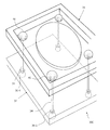
- frame
- string
- support device
- shaped member
- vibration
- Prior art date
- Legal status (The legal status is an assumption and is not a legal conclusion. Google has not performed a legal analysis and makes no representation as to the accuracy of the status listed.)
- Ceased
Links
Images







Classifications
-
- B—PERFORMING OPERATIONS; TRANSPORTING
- B64—AIRCRAFT; AVIATION; COSMONAUTICS
- B64C—AEROPLANES; HELICOPTERS
- B64C27/00—Rotorcraft; Rotors peculiar thereto
- B64C27/04—Helicopters
-
- B—PERFORMING OPERATIONS; TRANSPORTING
- B64—AIRCRAFT; AVIATION; COSMONAUTICS
- B64U—UNMANNED AERIAL VEHICLES [UAV]; EQUIPMENT THEREFOR
- B64U20/00—Constructional aspects of UAVs
- B64U20/80—Arrangement of on-board electronics, e.g. avionics systems or wiring
- B64U20/87—Mounting of imaging devices, e.g. mounting of gimbals
-
- G—PHYSICS
- G03—PHOTOGRAPHY; CINEMATOGRAPHY; ANALOGOUS TECHNIQUES USING WAVES OTHER THAN OPTICAL WAVES; ELECTROGRAPHY; HOLOGRAPHY
- G03B—APPARATUS OR ARRANGEMENTS FOR TAKING PHOTOGRAPHS OR FOR PROJECTING OR VIEWING THEM; APPARATUS OR ARRANGEMENTS EMPLOYING ANALOGOUS TECHNIQUES USING WAVES OTHER THAN OPTICAL WAVES; ACCESSORIES THEREFOR
- G03B15/00—Special procedures for taking photographs; Apparatus therefor
-
- G—PHYSICS
- G03—PHOTOGRAPHY; CINEMATOGRAPHY; ANALOGOUS TECHNIQUES USING WAVES OTHER THAN OPTICAL WAVES; ELECTROGRAPHY; HOLOGRAPHY
- G03B—APPARATUS OR ARRANGEMENTS FOR TAKING PHOTOGRAPHS OR FOR PROJECTING OR VIEWING THEM; APPARATUS OR ARRANGEMENTS EMPLOYING ANALOGOUS TECHNIQUES USING WAVES OTHER THAN OPTICAL WAVES; ACCESSORIES THEREFOR
- G03B17/00—Details of cameras or camera bodies; Accessories therefor
- G03B17/56—Accessories
-
- G—PHYSICS
- G03—PHOTOGRAPHY; CINEMATOGRAPHY; ANALOGOUS TECHNIQUES USING WAVES OTHER THAN OPTICAL WAVES; ELECTROGRAPHY; HOLOGRAPHY
- G03B—APPARATUS OR ARRANGEMENTS FOR TAKING PHOTOGRAPHS OR FOR PROJECTING OR VIEWING THEM; APPARATUS OR ARRANGEMENTS EMPLOYING ANALOGOUS TECHNIQUES USING WAVES OTHER THAN OPTICAL WAVES; ACCESSORIES THEREFOR
- G03B5/00—Adjustment of optical system relative to image or object surface other than for focusing
-
- H—ELECTRICITY
- H04—ELECTRIC COMMUNICATION TECHNIQUE
- H04N—PICTORIAL COMMUNICATION, e.g. TELEVISION
- H04N5/00—Details of television systems
- H04N5/222—Studio circuitry; Studio devices; Studio equipment
-
- B—PERFORMING OPERATIONS; TRANSPORTING
- B64—AIRCRAFT; AVIATION; COSMONAUTICS
- B64U—UNMANNED AERIAL VEHICLES [UAV]; EQUIPMENT THEREFOR
- B64U10/00—Type of UAV
- B64U10/10—Rotorcrafts
- B64U10/17—Helicopters
-
- B—PERFORMING OPERATIONS; TRANSPORTING
- B64—AIRCRAFT; AVIATION; COSMONAUTICS
- B64U—UNMANNED AERIAL VEHICLES [UAV]; EQUIPMENT THEREFOR
- B64U2101/00—UAVs specially adapted for particular uses or applications
- B64U2101/30—UAVs specially adapted for particular uses or applications for imaging, photography or videography
Definitions
- the present invention relates to a support device for an imaging device. More specifically, the present invention relates to a support device that is mounted on a moving body such as a rotary wing machine to support the imaging device and reduces vibration of the moving body transmitted to the imaging device, and a rotor having the supporting device. Regarding the machine.
- the imaging device When suspending an imaging device such as a camera on a rotary wing machine such as an unmanned helicopter, the imaging device may be suspended via a vibration damping device or a gimbal. These devices are required to have a load resistance for suspending an image pickup device, which is a heavy object, and a function for suppressing vibration. By using a gimbal or the like, it is possible to reduce vibration and suppress blur of a captured still image and/or moving image.
- Patent Document 1 discloses a technique in which a body bracket and a platform are supported with a spring compressed to suppress low-frequency vibration.
- Patent Document 2 mainly discloses a technique for suppressing low-frequency vibration.
- Patent Documents 1 and 2 also mention suppression of high frequency vibration.
- Patent Document 1 proposes removing the influence of high-frequency vibrations on an image by software processing of an image control device.
- Patent Document 2 high-frequency vibration is removed by using a complicated mechanism such as a gyro.
- Patent Document 1 does not disclose a specific method for removing the influence of high-frequency vibration on an image by software processing of an image control device.
- high-frequency vibrations may not be completely removed and may remain. It is desirable to physically remove high frequency vibrations.
- the camera mounting platform has a structure in which it is suspended from a column via a rubber cord.
- the elastic cord is stretched, the suspended portion is not kept horizontal and becomes like a pendulum, which may increase the amount of movement of the suspended camera. With this, even if the low-frequency and high-frequency vibrations can be removed, the captured still image or moving image may be blurred.
- One of the objects of the present invention is to suppress the transmission of high-frequency vibrations generated from the rotorcraft to the imaging device.
- An exemplary support device is a support device for an imaging device, in which the first frame mounted on the rotorcraft and the imaging device are mounted directly or indirectly, for example via a gimbal.
- the second frame is suspended from the first frame using a string-shaped member, and is supported in a plane by at least three points by the string-shaped member.
- the support device is attached to the rotary wing machine, it is possible to reduce the influence of horizontal vibration and/or vertical vibration applied to the first frame from the rotary wing machine to perform imaging.
- the amplitude of the vibration is from the fulcrum (for example, a fastener) of the string-shaped member of the first frame 31 to the string-shaped member on the second frame side.
- the length of the cord-like member up to the fulcrum is sufficiently smaller than the natural frequency of the low frequency determined by the weight of the first frame and after and the length of the cord-like member.
- the natural frequency is, for example, a vibration having a frequency that can be corrected by a camera shake correction function that can be mounted on the image pickup apparatus.
- the vibrations applied in the downward direction in the vertical direction cause the string-shaped member to bend.
- the vibration is attenuated and transmitted to the second frame within the range where the vibration is applied vertically downward.
- the at least one cord-like member regulates relative movement of the first frame and the second frame in a direction in which the first frame and the second frame are separated from each other, and the first frame and the second frame are separated from each other. Allows relative movement in the directions toward each other.
- the at least one string-shaped member allows relative movement of the first frame and the second frame in a direction toward each other. More specifically, in one embodiment, the at least one cord-like member has a constant length between the first frame and the second frame, whereby the first frame The frame and the second frame are restricted from moving relative to each other in a direction away from each other, and the at least one string-shaped member is flexible, whereby the first frame and the second frame are The frame and the frame are allowed to move relative to each other. At least one string-shaped member has flexibility, and by bending, the first frame and the second frame 32 can be relatively moved in a direction in which they approach each other. Thereby, the vibration transmitted from the first frame 31 to the second frame 32 can be reduced.
- the material of the at least one string-shaped member is fiber.
- the fibers are chemical fibers.
- the first frame has at least one hole at a position facing the second frame, and the at least one cord-shaped member passes through the at least one hole.
- the string-shaped member is configured to pass through the hole formed in the first frame.
- the vibration of the first frame may be transmitted as it is to the second frame via the string-like member.
- the coupling state between the frame and the string becomes loose, so that the transmission of vibration can be further reduced.
- the vibration of the first frame is blocked and is not transmitted to the second frame, so that the transmission of vibration can be further reduced.
- the at least one cord-like member has a member or a knot having a diameter larger than the diameter of the at least one hole, and the member or knot is the same with respect to the at least one hole. Located on the opposite side of the second frame.
- the string-shaped member has a member or knot having a diameter larger than the diameter of the hole. This prevents the cord-like member from falling out of the hole.
- the at least one string-shaped member is slidable in the at least one hole.
- the cord-like member When the first frame and the second frame approach each other, the cord-like member is relatively pushed in the direction of the first frame by the second frame. At this time, since the string-like member is not fixed in relation to the hole, the string-like member enters the hole while flexing in some cases. As a result, the vibration transmitted to the second frame via the string-shaped member is reduced.
- the second frame has three or more holes at positions facing the first frame, and the at least one cord-shaped member passes through each of the three or more holes.
- the second frame is supported in a plane at at least three points.
- the string-like member is configured to pass through the hole formed in the second frame. As a result, it is possible to provide a variety of attachment methods for the string-shaped member.
- the at least one string-shaped member has a member or knot having a diameter larger than each diameter of the three or more holes, and the member or knot has the three or more members. Located on the opposite side of the first frame with respect to each of the holes.
- the string-shaped member has a member or knot having a diameter larger than the diameter of the hole. This prevents the cord-like member from falling out of the hole.
- the at least one cord-shaped member can slide in each of the three or more holes.
- the second frame has four holes at positions facing the first frame.
- the second frame has four holes at positions facing the first frame. Since the string-like member passes through each hole, the second frame can be supported more stably at four points as compared with the case where it is supported at three points.
- the four holes of the second frame are arranged in a rectangular shape in a plan view.
- the four holes are arranged in a rectangular shape in plan view, it is easy to adjust the hole arrangement. Thereby, the second frame having the holes can be manufactured more easily.
- the supporting device when the direction in which the second frame is suspended from the first frame is referred to as a vertical direction and the direction vertical to the vertical direction is referred to as a horizontal direction, the supporting device includes the first frame. And a damper for damping the vibration in the vertical direction and/or a damper for damping the vibration in the horizontal direction.
- the support device further includes a third frame between the first frame and the second frame, the third frame being mechanically connected to the second frame and having the imaging device attached thereto.
- a first damper for damping the horizontal vibration is provided between the first frame and the second frame, and a vertical damper for damping the vertical vibration is provided between the second frame and the third frame.
- a first damper for damping horizontal vibration is provided between the first and second frames
- a second damper for damping vertical vibration is provided between the second and third frames. ..
- the damper coefficient of the first damper By adjusting the damper coefficient of the first damper, the horizontal vibration input to the second frame can be controlled to a desired magnitude, and by adjusting the damper coefficient of the second damper, the horizontal vibration can be input to the third frame.
- the vertical vibration can be controlled to a desired magnitude. This makes it possible to appropriately control the vertical and horizontal vibrations input to the third frame.
- a rotary wing machine performs a shake correction in a horizontal direction and a vertical direction, with any of the above-described supporting devices, a rotary wing, a prime mover that rotates the rotary wing, a body that houses the prime mover.
- An imaging device with a shake correction mechanism is fixed to the second frame of the support device.
- the vertical and horizontal vibrations input to the first frame are converted into lower frequency vibrations, and the remaining vibrations are further removed by the shake correction mechanism.
- the shake correction mechanism As a result, it is possible to perform shooting with greatly reduced blur.
- the rotary wing aircraft further includes a gimbal, and the second frame and the imaging device are indirectly fixed via the gimbal.
- the orientation of the image pickup device can be kept almost constant. Since the correction by the blur correction mechanism can be performed more effectively, it is possible to perform shooting with greatly reduced blur.
- the second frame to which the imaging device is directly or indirectly attached is suspended from at least one string-shaped member from the first frame attached to the rotary wing machine.
- At least one string-shaped member supports the second frame in a plane at at least three points.
- FIG. 6 is a diagram schematically illustrating a side surface of an exemplary support device. It is a figure which shows the string-shaped member bent. It is a figure which shows an example of a behavior of a string-shaped member when all the fasteners and the 1st frame and the 2nd frame are not fixed.
- the horizontal sway (vibration) transmitted to the first frame is transmitted to the second frame via the string-shaped member, so that the second frame makes a rotational movement in the direction of the arrow in the vertical plane.
- FIG. 3 is a front view of an exemplary support device.
- FIG. FIG. 6 is a side view of an exemplary support device.
- FIG. 6 is a partial perspective view of the supporting device when viewed from above.
- FIG. 8 is a top transparent view of a support device according to a variation of the exemplary embodiment. It is a figure which shows the example of the string-shaped member which has a knot.
- (A) And (b) is a figure which shows the relationship between the hole of a 1st frame, and a string-shaped member.
- FIG. 6 is a diagram schematically illustrating a side surface of an exemplary support device including a metal fastener and a metal wire.
- an unmanned helicopter equipped with an engine is exemplified as the rotary wing aircraft, but a manned helicopter may be used. Alternatively, it may be an electric helicopter equipped with an electric motor instead of the engine.
- a drive device represented by a heat engine such as an electric motor that is an electric motor and an engine may be referred to as a “motor”.
- the unmanned helicopter 1 is an external side view of the unmanned helicopter 1.
- the unmanned helicopter 1 includes a body 4 having a main body 2 and a tail body 3.
- a main rotor 5 is provided above the main body 2, and a tail rotor 6 is provided behind the tail body 3.
- a radiator 7 is provided at the front of the main body 2.
- the main body 2 accommodates an engine, an intake system, a main rotor shaft, and a fuel tank, all of which are not shown.
- a control panel 8 is provided on the upper rear side of the main body 2, and an indicator lamp 11 is provided on the lower rear side.
- the control panel 8 displays a checkpoint before flight, a self-check result, and the like.
- the display on the control panel 8 can also be confirmed at the ground station.
- the indicator lamp 11 displays a state of GPS control, an abnormality warning of the machine body, and the like.
- the image pickup device 20 is attached to the lower side of the central portion of the main body 2 via a support device 30.
- the imaging device 20 is, for example, a CCD camera, a CMOS camera, a hyperspectral camera, a multispectral camera, or an infrared camera capable of capturing a still image and/or a moving image.
- the image pickup device 20 has a blur correction mechanism capable of performing blur correction in the horizontal direction and the vertical direction (so-called camera shake correction).
- the blur correction mechanism may operate in either an optical type or an electronic type, for example.
- the optical image stabilization mechanism changes the position of the lens or the image pickup device so as to cancel the camera shake, and enables the capturing of still images and/or moving images without camera shake.
- the electronic image stabilization mechanism reads the image into the buffer memory at the time of shooting, compares the first captured image with the images captured after that, calculates the amount of movement of the subject, and determines the shootable area. It automatically shifts to enable shooting without camera shake.
- Electronic image stabilization is relatively effective mainly when shooting moving images. Since any method is well known, further detailed description will be omitted.
- Automatic flight control box 15 is mounted on the main body 2.
- the automatic flight control box 15 accommodates, for example, a GPS control device (not shown), a triaxial acceleration sensor, a geomagnetic sensor, a communication device, a signal processing circuit such as a microcomputer, and a storage device.
- the GPS control device acquires flight data such as the current position and flight speed using GPS (Global Positioning System).
- the triaxial acceleration sensor detects each data of roll acceleration, pitch angular velocity, and yaw acceleration of the unmanned helicopter 1.
- the geomagnetic sensor detects the current direction of the unmanned helicopter 1.
- the current attitude of the unmanned helicopter 1 can be determined by using the data (machine data) output from each of the triaxial acceleration sensor and the geomagnetic sensor. Flight data and airframe data are provided to the signal processing circuitry.
- the communication device wirelessly communicates with the ground.
- the signal processing circuit executes the control program stored in the storage device to realize automatic flight of the unmanned helicopter 1.
- the automatic flight is performed based on the above-mentioned flight data, airframe data, operating state data such as engine speed and throttle opening.
- the signal processing circuit uses flight data, airframe data, driving state data, etc. to automatically select a predetermined driving mode or control program, or by a command from the ground station, Operate optimally according to the driving condition, and fly to or near the destination by yourself.
- the user may fly the unmanned helicopter 1 by using a remote controller (not shown) based on the flight state and various operating state data transmitted from the aircraft while visually confirming the flight state. ..
- a remote control receiving antenna 23 that receives a command signal from the remote controller is provided.
- the imaging device 20 can interfere with the ground when the unmanned helicopter 1 is taking off and landing. Therefore, the unmanned helicopter 1 may be provided with a supporting leg or skid (not shown) having a length (height) such that the imaging device 20 does not interfere with the ground while the unmanned helicopter 1 is stationary on the ground.
- the frequency of the above-mentioned camera shake is, for example, about 35 Hz or less, and more specifically, 30 Hz or less.
- the frequency of such camera shake is referred to as "low frequency" in this specification.
- the image stabilization function can suppress low-frequency vibration.
- a frequency higher than the upper limit of the low frequency is referred to as a “high frequency”.
- f>30 Hz where f is the upper limit of the frequency that can be suppressed by the camera shake correction function, it can be defined that the upper limit of the low frequency frequency is fHz and the lower limit of the high frequency band is larger than fHz.
- the support device 30 causes the high frequency vibrations generated by the high speed rotation of the engine or the main rotor 5 and the lift force and the gravity to be transmitted to the support device 30 at a low frequency. Convert to vibration. High frequency vibrations can occur both horizontally and vertically.
- the support device 30 converts horizontal high-frequency vibrations into horizontal low-frequency vibrations. Further, the support device 30 halves at least the vertically downward vibration of the high frequency vibration in the vertical direction. Low frequency vibrations can be corrected by the image stabilization function. Accordingly, it is possible to suppress blurring of a still image or a moving image captured by the imaging device 20.
- At least one cord-like member suspends the second frame from the first frame of the supporting device 30 and supports the second frame in a plane at at least three points, thereby suppressing vibration. Can be realized.
- the reason is as follows. It should be noted that at least three points are not arranged on one straight line. (1)
- the movement is restricted only in one axial direction (vertical direction or Z-axis direction). That is, the movement in the direction of pulling the string-like member (eg, vertically downward) is restricted, and the movement in the direction of pushing up the string-like member (eg: vertical upward) is not restricted.
- a damper may be installed to suppress vibration. However, when the damping coefficient of the damper is large (so-called when the damper is hard), some vibrations may be transmitted from the first frame to the second frame via the damper.
- FIG. 2 schematically shows a side view of the exemplary support device 30.
- the support device 30 has a first frame 31, a second frame 32, and cord-shaped members 34-1 and 34-2.
- the first frame 31 can function as a base for suspending the second frame 32 by the string-shaped members 34-1 and 34-2.
- the support device 30 is attached to the unmanned helicopter 1 (FIG. 1) via the first frame 31.
- the first frame 31 faces the lower portion of the unmanned helicopter 1.
- the first frame 31 is, for example, a screw hole for screwing a camera mount (not shown) provided in the lower part of the unmanned helicopter 1 or a hole for passing a band for fixing the camera mount and the first frame 31.
- the first frame 31 may have a clamp.
- the first frame 31 may be fixed to the unmanned helicopter 1 by sandwiching the camera mount or mount plate of the unmanned helicopter 1 with a clamp.
- the first frame 31 may have a plurality of claws.
- the first frame 31 may be fixed to the unmanned helicopter 1 by biting each claw on the lower portion of the unmanned helicopter 1.
- the support device 30 is attached to the unmanned helicopter 1.
- the first frame 31 does not have to have a special structure to be mounted on the unmanned helicopter 1. If the unmanned helicopter 1 has a fixing device such as a clamp or a claw, and the first frame 31 can be sandwiched or fixed by the claw, the first frame 31 may be a simple plate-shaped body.
- An image pickup device is directly or indirectly attached to the second frame 32.
- the imaging device 20 is indirectly attached to the second frame 32 via the arm 22.
- a gimbal described later may be provided instead of the arm 22.
- a "gimbal" is a type of rotary table that rotates an object around one or more axes.
- the gimbal having a plurality of axes is configured by combining a plurality of uniaxial gimbals. By making the axes orthogonal to each other, the orientation of the camera mounted on the inner gimbal can be always kept constant.
- the imaging device 20 may be directly attached to the second frame 32.
- the cord-shaped members 34-1 and 34-2 suspend and support the second frame 32 from the first frame 31.
- the material of the string-shaped members 34-1 and 34-2 is a fiber such as a chemical fiber. Being fibers, the string-shaped members 34-1 and 34-2 are thin, supple, and can be flexibly deformed. For example, the string-shaped members 34-1 and 34-2 can bend. When the material of the string-shaped members 34-1 and 34-2 is a chemical fiber, the strength and flexibility of the string-shaped members can be adjusted to desired specifications. Those skilled in the art can obtain an advantage (described later) by using the cord-shaped members 34-1 and 34-2 by using the cord-shaped members 34-1 and 34-2 having an appropriate elongation or flexural modulus. To be Wires made of metal such as stainless steel may be used as the string-shaped members 34-1 and 34-2.
- cord-shaped members 34-1 and 34-2 Only two cord-shaped members 34-1 and 34-2 are shown in FIG. 2, but this is for convenience of description in the drawing. If there are three or more cord-shaped members, the number is arbitrary. The same applies to the drawings showing the side surfaces of the similar supporting device described below, and the number thereof is arbitrary as long as there are three or more cord-shaped members.
- the reason why there are three or more is that the second frame 32 suspended from the first frame 31 can be planarly supported by the cord-shaped member, that is, stable.
- a specific supporting method will be described later with reference to FIG. 8 and the like. It should be noted that the more positions that support the second frame 32, the more stable the second frame 32 can be. That is, the second frame 32 can be more stable when it is supported at four points, compared to when it is supported at three points.
- Each of the first frame 31 and the second frame 32 has a plurality of holes.
- the first frame 31 has four holes on the surface facing the second frame 32.
- the second frame 32 has four holes on the surface facing the first frame 31.
- the cord-shaped members 34-1 and 34-2 pass through the holes provided in the first frame 31 and the second frame 32, respectively. Specifically, the cord-shaped member 34-1 passes through the hole 36-1 provided in the first frame 31 and the hole 36-2 provided in the second frame 32. The string-shaped member 34-2 passes through a hole 36-3 provided in the first frame 31 and a hole 36-4 provided in the second frame 32.
- Fasteners 38-1 to 38-4 are provided at the ends of the string-shaped members 34-1 and 34-2 to prevent the string-shaped members 34-1 and 34-2 from falling out of the holes. ing.
- the fasteners 38-1 and 38-3 bear the full load of the imaging device 20 and the support device 30. Further, the loads of the second frame 32 and the imaging device 20 are applied to the fasteners 38-2 and 38-4.
- the string-like member 34-1 and the fasteners 38-1 and 38-2 are fastened sufficiently firmly to withstand such a load.
- the string-shaped member 34-2 and the fasteners 38-3 and 38-4 are fastened sufficiently firmly.
- the fasteners 38-1 to 38-4 are made of metal, for example.
- any material and/or shape of the fastener can be used.
- An example of the shape of the fastener will be described later with reference to FIG. Further, it is not essential to provide the fastener separately from the string-shaped member.
- a knot can be created by tying a string-like member, and the knot can be used instead of the above-described fastener.
- the knot only needs to have a size, shape, and strength that prevent the string-shaped member under load from falling out of the hole.
- the knot may be reinforced with resin or the like.
- the holes 36-1 to 36-4 are supposed to be through holes provided in the first frame 31 or the second frame 32. However, if the above-mentioned fastener can prevent the string-like member from falling off, it may be a groove, for example. As used herein, holes can include grooves.
- any string-like member may be referred to by a reference numeral “34” that does not include a branch number, unless a specific string-like member is described.
- an arbitrary hole may be expressed by using the reference numeral “36” that does not include the branch number. The same applies to the fasteners 38-1 to 38-4.
- the fastener and the first frame 31, and/or the fastener and the second frame 32 may be fixed or may not be fixed.
- the vibration from the unmanned helicopter 1 input to the first frame 31 is not transmitted to the second frame 32 under a certain condition.
- the condition is, for example, the case where the first frame 31 and the second frame 32 move in a direction relatively approaching each other during flight of the unmanned helicopter 1.
- the operation of the unmanned helicopter 1 that is rising is suddenly switched from hovering to hovering. Since the first frame 31 is attached to the unmanned helicopter 1, the behavior of the first frame 31 matches the behavior of the unmanned helicopter 1. On the other hand, the second frame 32 continues to move upward with the upward speed at the time when the rising is stopped as the initial speed, and relatively approaches the first frame 31.
- FIG. 3A schematically shows the bent string members 34-1 and 34-2.
- the first frame 31 and the second frame 32 are non-parallel. The reason is that the first frame 31 can be tilted depending on the posture of the unmanned helicopter 1, for example.
- FIG. 3B shows an example of the behavior of the cord-shaped members 34-1 and 34-2 when all the fasteners and the first frame 31 and the second frame 32 are not fixed.
- the cord-shaped members 34-1 and 34-2 are connected to the holes 36-1 and 36-2 of the first frame 31 as illustrated.
- Slides 36-3 FIG. 2 can cause fasteners 38-1 and/or fasteners 38-3 to separate from first frame 31.
- the string-shaped members 34-1 and 34-2 slide inside the holes 36-2 and 36-4 (FIG.
- the fasteners 38-2 and/or the fasteners 38- are formed. 4 can be separated from the second frame 32. Further, at this time, the string-shaped members 34-1 and 34-2 can bend. In some cases, the cord-shaped members 34-1 and 34-2 may flex and enter the hole. Even if a high-frequency vibration is input to the first frame 31, it is not transmitted from the string-shaped members 34-1 and 34-2 to the second frame 32 and the like.
- one of the fasteners 38-1 and 38-2 may be fixed to the frame and the other may not be fixed to the frame.
- one of the fasteners 38-3 and 38-4 may be fixed to the frame and the other may not be fixed to the frame.
- the fastener can be separated from the first frame 31 or the second frame 32, and the string-shaped members 34-1 and 34-2 can bend. In that case, most of the high-frequency vibration input to the first frame 31 (substantially all high-frequency vibration) is transmitted to the second frame 32 and the like below via the cord-shaped members 34-1 and 34-2. Not transmitted.
- the imaging device 20 Since the high frequency vibration is not transmitted to the second frame 32, the imaging device 20 is also not affected by the high frequency vibration. Therefore, blurring of a still image or a moving image can be suppressed.
- the support device 30 it is possible to reduce the influence of vibration even when the first frame 31 and the second frame 32 are relatively close to each other. For example, this is a case where the unmanned helicopter 1 is hovering. It can be assumed that high-frequency vibrations in the vertical direction (vertical direction) randomly occur during hovering. Of the high-frequency vibrations in the vertical direction (vertical direction) input to the first frame 31, the downward vibration is not transmitted from the first frame 31 to the second frame 32 or is very small even if transmitted. Conceivable. The reason is that, when downward vibration is input to the first frame 31, it can be microscopically considered that the first frame 31 and the second frame 32 are moving in a direction relatively approaching each other. Is.
- the high frequency vibration transmitted from the first frame 31 to the second frame 32 can be at least approximately halved during hovering.
- the string-shaped members 34-1 and 34-2 are fully extended, and each fastener contacts the first frame 31 or the second frame 32. Therefore, the high-frequency vibration input to the first frame 31 can be transmitted to the imaging device 20 via the second frame 32.
- FIGS. 4A and 4B show how the horizontal shaking (vibration) transmitted to the first frame 31 is transmitted to the second frame 32 by the string-shaped members 34-1 and 34-2. More specifically, in FIGS. 4A and 4B, the force transmitted through the cord-shaped members 34-1 and 34-2 causes the second frame 32 to rotate in the direction of the arrow in the vertical plane. It shows the situation.
- the force T that the second frame 32 receives from the string-shaped members 34-1 and 34-2 is so-called tension, and the direction thereof is the direction in which the second frame 32 is pulled from the string-shaped members 34-1 and 34-2. ..
- the direction of the force T also changes at high frequency. Therefore, the component force (vertical upward) of the force T in the vertical direction (Z-axis direction) continues to fluctuate slightly at high frequencies.
- the fluctuation of the high frequency is sufficiently small as compared with the vertically downward gravity received by the second frame 32 and the imaging device 20. Therefore, the component component of the force T in the vertical direction (Z-axis direction) always keeps balance with the gravity received by the second frame 32 and the imaging device 20. Virtually, there is no change in the force balance in the vertical direction.
- a horizontal component of the force T that is, a component in a plane (horizontal plane) direction perpendicular to the Z-axis vibrates the second frame 32 and the imaging device 20 in a plane (vertical plane) including the Z-axis.
- the "vibration” here means a vibration in a vertical plane.
- a typical example of vibration in the vertical plane is pendulum motion (rotational motion) in the vertical plane.
- the vibration in the vertical plane assumed in the present embodiment is different from the periodic vibration like the simple pendulum. Please note.
- the amplitude thereof defines the magnitude of the maximum amplitude from the fulcrum (for example, a fastener) of the string-like member 34 on the first frame 31 side. If the length of the string-like member 34 up to the fulcrum (for example, a fastener) of the string-like member 34 on the second frame 32 side is sufficiently smaller, the mass of the first frame 31 or less and the length of the string-like member 34 determine. Vibrations of natural frequency are transmitted. Other vibrations are not transmitted. For example, if the length of the string-shaped member 34 is about 2 cm or more, vibration in a vertical plane of about 20 Hz or less is transmitted.
- This level of vibration can be corrected, for example, by a camera shake correction function that can be mounted on the imaging device 20, or a camera shake correction function of a gimbal (described later).
- the “fastener” is illustrated as the fulcrum of the string-shaped member 34, but it may not be the fastener.
- the edge of the hole on the surface of the first frame 31 on the side facing the second frame 32 may serve as a fulcrum on the first frame 31 side.
- the edge of the hole on the surface of the second frame 32 on the side facing the first frame 31 may serve as a fulcrum on the second frame 32 side.
- FIG. 5A and 5B are front and side views of an exemplary support device 30A.
- FIG. 6 is a partial perspective view of the supporting device 30A as viewed from above.
- the second frame 32 is not shown in FIG.
- the broken line represents the edge when the first frame 31 and the like are transmitted.
- the shapes of the first frame 31 and the second frame 32 shown in FIGS. 5A and 5B are different from those shown in FIG.
- the first frame 31 and the second frame 32 have openings 42a and 42b, respectively.
- the first frame 31 and the second frame 32 can have various shapes as long as they have spaces (holes, grooves, etc.) for passing the cord-shaped members 34-1, 34-2.
- the presence or absence of the structure for attaching to the unmanned helicopter 1 is not essential for the first frame 31.
- the supporting device 30A has a third frame 33 in addition to the first frame 31 and the second frame 32.
- the arm 22 directly attached to the second frame 32 is directly attached to the third frame 33.
- the rod-shaped arm 22 is substantially U-shaped (FIG. 5B).
- the second frame 32 is the same as the configuration shown in FIG. 2 and the like in that it is suspended from the first frame 31 via the cord-shaped members 34-1 and 34-2.
- the third frame 33 is connected to the second frame 32 via a plurality of dampers, such as the damper 40, and is also directly connected to the arm 22.
- the arm 22 connected to the third frame 33 extends downward and passes through the opening 42 a of the first frame 31 and the opening 42 of the second frame 32 in order.
- the arm 22 is one of the constituent elements of the gimbal 10.
- the gimbal 10 existing below the arm 22 is a kind of a turntable capable of rotating the imaging device 20 about three orthogonal axes X1 to X3.
- the imaging device 20 is fixed to a mount provided on the axis X3. Thereby, the orientation of the imaging device 20 can be kept substantially constant.
- the imaging device 20 is indirectly fixed to the third frame 33, the second frame 32, and the first frame 31 via the gimbal.
- a damper is a device that attenuates or eliminates vibration energy to reduce the amplitude of shock or vibration.
- the damper 40 will be described as an example.
- the other dampers have the same function, arrangement, and configuration as the damper 40, but the description thereof is omitted.
- the damper 40 is disposed between the lower second frame 32 and the upper third frame 33, and the vibration input from the second frame 32 is arranged between the damper 40 and the third frame 33. Attenuate.
- the unmanned helicopter 1 when the unmanned helicopter 1 rises, even if a string-shaped member is provided, the high frequency vibration in the vertical direction can be halved but not completely damped.
- the high-frequency vibration applied from the unmanned helicopter 1 to the first frame 31 can be transmitted to the second frame 32.
- vertical downward and upward vertical natural frequency vibrations can be transmitted to the second frame 32, the third frame 33, the gimbal 10, and the imaging device 20.
- the vibration at this time is mainly vibration (rotational motion) about the center of gravity of the gimbal 10 and the imaging device 20.
- the damper 40 by providing the damper 40, the damping force according to the speed of the vibration applied vertically downward and upward is applied to the second frame 32 in the direction opposite to the speed direction. Thereby, the vibration in the vertical direction can be further effectively damped. As a result, the high frequency vibration in the vertical direction, which is input from the second frame 32, is significantly attenuated or substantially removed, and the vibration transmitted to the third frame 33 can be significantly suppressed. In addition, even when the unmanned helicopter 1 is raised, it may be assumed that a slight vibration is transmitted to the second frame 32. Since such vibration is also reduced by the damper 40, the transmission to the third frame 33 can be suppressed.
- FIG. 7 is a top transparent view of a supporting device 30B according to a modified example of this embodiment.
- the difference between the support device 30B and the support device 30A described above is that a plurality of dampers 44 are newly provided.
- the plurality of dampers 44 are provided between the first frame 31 and the second frame 32 to reduce horizontal vibration.
- the horizontal direction in FIG. 7 is an arbitrary direction on a plane formed by two orthogonal arrows shown in the upper left of the drawing.
- the other structure is the same as that of the supporting device 30A.
- the viscosity coefficient of the damper When the viscosity coefficient of the damper is increased, vibration can be transmitted from one frame to the other frame as it is via the damper. Therefore, it is preferable that the viscosity coefficient of the damper is not too high.
- the viscosity coefficient can be determined under various conditions. Those skilled in the art can determine an appropriate viscosity coefficient according to, for example, the size and weight of the damper, the expected range of input, and the like.
- a metal ball is used as a fastener.
- the fastener need not be a metal ball as long as it can prevent the string-like member 34 from falling off.
- FIG. 8 shows an example of the string-shaped member 34 having a metal ball 46 which is a fastener.
- a metal ball 46 which is a fastener.
- reference numerals are given only to the two cord-shaped members and the two metal balls 46, but the illustrated four cord-shaped members and the four metal balls are the same.
- the cord-shaped member 34 may have the metal balls 46.
- the size of the metal ball 46 is larger than each diameter of the holes opened in the first frame 31. More specifically, the diameter of the metal sphere projected on the plane including the opening of the hole, for example, the plane parallel to the surface of the first frame 31, is larger than each diameter of the opened hole.
- the relationship described above is the same for the fasteners 38-1 to 38-4 (FIG. 2, etc.). As a result, it is possible to prevent the string-shaped member from falling out of the hole.
- the second frame 32 is supported by four cord-shaped members 34 passing through four holes (for example, holes 36-2 and 36-4) provided at four corners.
- the second frame 32 is stably supported in a plane.
- the four support points are provided at the four corners of the second frame 32, and are arranged in a rectangular shape in a plan view. With such an arrangement, it is easy to adjust the arrangement of the holes. This allows the second frame 32 having holes to be manufactured more easily.
- FIG. 9 shows the relationship between the hole 36 of the first frame 31 and the cord-shaped member 34.
- A shows a state in which the metal ball 46 stops on the surface of the first frame 31 around the opening of the hole 36, thereby preventing the string-like member 34 from falling out of the hole 36. At this time, the cord-shaped member 34-1 is fully extended.
- (b) shows a state in which the cord-shaped member 34 slides in the hole 36 and pushes up the metal ball 46. At this time, it is understood that the string-shaped member 34-1 is slightly bent.
- the state of (b) corresponds to the state shown in FIG. 3B.
- the high frequency vibration transmitted to the first frame 31 can be directly transmitted downward via the metal ball 46 and the cord-shaped member 34.
- the vibration can be transmitted to the second frame 32.
- the metal ball 46 is separated from the surface of the first frame 31 by the distance D (>0). Therefore, the high-frequency vibration transmitted to the first frame 31 does not propagate downward through the metal balls 46 and the string-shaped member 34. Even if the inner surface or opening of the hole 36 is in contact with the string-like member 34, the bending of the string-like member 34 significantly reduces or blocks the vibration transmitted through the string-like member 34.
- Whether or not the vibration is transmitted to the second frame 32 may change depending on whether or not the metal ball 46 is in contact with the surface of the second frame 32.
- the second frame 32 was supported at four points by the four string-shaped members 34.
- the “four string-shaped members 34” need not be physically four, and may be at least one.
- FIG. 10 illustrates an example in which the second frame 32 is apparently supported by four cord-shaped members by pulling around one cord-shaped member 50.
- the first frame 31 and the second frame 32 are provided with a plurality of holes.
- the string-shaped member 50 can slide in each hole.
- the second frame 32 can be stably supported in a planar manner at a plurality of points. Note that the fasteners or knots are omitted in FIG. 10.
- the string member 50 may be fixed to the first frame 31 and/or the second frame 32.
- the second frame 32 it is not essential to support the second frame 32 at four points, and if there are three or more points, the second frame 32 can be stably supported. However, this does not apply when all points are arranged on one straight line.
- FIG. 11 schematically illustrates a side view of an exemplary support device 30E having metal fasteners 38-1 to 38-4 and metal wires 34-1 and 34-2 that are cord-shaped members. ing.
- the fasteners 38-1 to 38-4 are cylindrical weight types.
- the fasteners 38-1 and 38-2 are connected to each other by a wire 34-1.
- Fasteners 38-3 and 38-4 are connected to each other by wire 34-2.
- both fasteners 38-1 and 38-2 are provided between the first frame 31 and the second frame 32 so as to face each other.
- the wire 34-1 connected to the fastener 38-1 reaches the +Z side surface from the ⁇ Z side surface of the first frame 31 through the hole 36-5 provided in the first frame 31, It extends to the hole 36-1 on the side surface. After that, the wire 34-1 extends through the hole 36-1 to the ⁇ Z side surface of the first frame 31 again, and enters the hole 36-2 from the +Z side surface of the second frame 32 as it is to the ⁇ Z side surface. To reach.
- the wire 34-1 extends to the hole 36-6 on the ⁇ Z side surface of the second frame 32 and reaches the +Z side surface of the second frame 32 through the hole 36-6.
- the wire 34-1 is then connected to the fastener 38-2. As shown, the wires 34-2 connected to the fasteners 38-3 and 38-4 are also connected in exactly the same manner, and the description thereof will be omitted.
- the influence of the shift of the fastener 38 due to the vibration can be greatly reduced. Since the position of the fastener 38 is unlikely to change, the wire 34 can be held at a fixed position in the hole 36 even if the diameter of the metal wire 34 is smaller than the diameter of the hole 36. Even if the position of the fastener 38 deviates in any direction on the XY plane, the position of the fulcrum of the wire 34 is generally maintained. Therefore, the wire 34 can be held at a fixed position in the hole 36.
- the cord-shaped member (wire) 34 may be made of chemical fiber or metal.
- the length of the string member 34 is constant between the first frame 31 and the second frame 32. That is, the length of the string-shaped member 34 does not substantially change. Therefore, the cord-shaped member 34 regulates the relative movement of the first frame 31 and the second frame 32 in the direction in which they are separated from each other.
- the string-shaped member 34 has flexibility. Therefore, the cord-shaped member 34 bends when the first frame 31 and the second frame 32 relatively move in the direction in which the first frame 31 and the second frame 32 approach each other, so that the first frame 31 and the second frame 32 are separated from each other by the cord-shaped member 34-. It is possible to get closer than the length of 1.
- the support devices 30, 30A to 30E of the imaging device 20 include a first frame 31 attached to the rotary wing machine 1 and a second frame 32 to which the imaging device 20 is attached directly or indirectly. , At least one cord-like member 34 that suspends the second frame 32 from the first frame 31, and that supports the second frame 32 in a planar manner at at least three points. I have it.
- the imaging device 20 can reduce high-frequency vibration and perform shooting.
- At least one cord-shaped member 34 restricts relative movement of the first frame 31 and the second frame 32 in a direction away from each other, and the first frame 31 and the second frame 32 are separated from each other. Allows relative movement in the directions toward each other.
- At least one cord-shaped member 34 allows relative movement of the first frame 31 and the second frame 32 in a direction in which they approach each other. More specifically, in one embodiment, the at least one cord-like member has a constant length between the first frame and the second frame, whereby the first frame The frame and the second frame are restricted from moving relative to each other in a direction away from each other, and the at least one string-shaped member is flexible, whereby the first frame and the second frame are The frame and the frame are allowed to move relative to each other.
- at least one string-shaped member has flexibility, and by bending, the first frame 31 and the second frame 32 can be relatively moved in a direction in which they approach each other. Thereby, the vibration transmitted from the first frame 31 to the second frame 32 can be reduced.
- the material of at least one cord-shaped member 34 is fiber.
- at least one cord-shaped member 34 is thin, supple, and can be flexibly deformed.
- the fiber is a chemical fiber. Since the chemical fiber can be artificially produced, the strength and flexibility of the string-shaped member can be adjusted to desired specifications.
- the first frame 31 has at least one hole 36 at a position facing the second frame 32, and at least one cord-shaped member 34 passes through at least one hole 36. Since the diameter of the string-shaped member 34 is smaller than the diameter of the hole 36, the flexible string-shaped member 34 can be used.
- At least one cord-shaped member 34 has a member (fastener 38) or knot having a diameter larger than the diameter of at least one hole 36.
- the fasteners 38 or knots are located opposite the second frame 32 with respect to the at least one hole 36. This makes it possible to suspend the second frame 32 while preventing at least one cord-shaped member 34 from falling off.
- At least one cord-shaped member is slidable in the at least one hole.
- the first frame 31 and the second frame 32 can move in the directions toward each other.
- the second frame 32 has three or more holes 36 at positions facing the first frame 31, and at least one cord-shaped member 34 is provided in each of the three or more holes 36. Pass through. Accordingly, the second frame 32 can be supported in a plane at least at three points.
- the string-shaped member 34 has a member (fastener 38) or a knot having a diameter larger than each diameter of the three or more holes 36, and the member or knot has three or more members. Located on the opposite side of the first frame with respect to each of the holes 36 of. As a result, the relative movement of the first frame 31 and the second frame 32 in the direction away from each other is restricted, while the relative movement in the direction toward each other is permitted.
- At least one cord-shaped member 34 can slide in each of the three or more holes 36.
- the first frame 31 and the second frame 32 can move in the directions toward each other.
- the second frame 32 has four holes at positions facing the first frame 31.
- the at least one cord-shaped member 34 can slide in more holes than the three holes, and also supports the second frame 32 in a plane at at least four points.
- the second frame 32 can be supported more stably by supporting at four points as compared with the case of supporting at three points.
- the four holes 36 of the second frame 32 are arranged in a rectangular shape in plan view. By arranging in a rectangular shape, the arrangement of each hole can be easily adjusted. Thereby, the second frame having the holes can be manufactured more easily.
- the supporting device when the direction in which the second frame 32 is suspended from the first frame 31 is referred to as the vertical direction and the direction vertical to the vertical direction is referred to as the horizontal direction, the supporting device is the first frame 31 and the first frame 31. Between the two frames 32, a damper 40 for damping vertical vibrations and/or a damper 44 for damping horizontal vibrations are further provided. By providing the damper, vertical and/or horizontal vibrations can be damped more quickly.
- the supporting device 30A further includes a third frame 33 between the first frame 31 and the second frame 32, which is mechanically connected to the second frame 32 and to which the image pickup device is attached.
- a first damper 44 for damping horizontal vibration between the first frame 31 and the second frame 32, and has a vertical vibration between the first frame 31 and the second frame 32.
- It has a second damper 40 for damping. This makes it possible to damp horizontal and vertical vibrations.
- a rotary wing machine 1 includes any one of the supporting devices 30, 30A to 30E described above, a rotary wing (main rotor) 5, a prime mover that rotates the rotary wing 5, and a machine body 4 that houses the prime mover.
- an image pickup device 20 having a shake correction mechanism capable of performing shake correction in the horizontal direction and the vertical direction, and the first frame 31 of the supporting devices 30, 30A to 30E and the machine body 4 are fixed,
- the second frame 32 of the supporting device 30, 30A to 30E and the imaging device 20 are directly or indirectly fixed to each other.
- the support device according to the present invention is useful when the imaging device is mounted on a moving body such as a rotorcraft such as a helicopter that generates high-frequency vibration.
Landscapes
- Engineering & Computer Science (AREA)
- Mechanical Engineering (AREA)
- Aviation & Aerospace Engineering (AREA)
- Physics & Mathematics (AREA)
- General Physics & Mathematics (AREA)
- Microelectronics & Electronic Packaging (AREA)
- Remote Sensing (AREA)
- Multimedia (AREA)
- Signal Processing (AREA)
- Accessories Of Cameras (AREA)
Abstract
回転翼機から発生する高周波の振動が撮像装置に伝わることを抑制する。撮像装置(20)の支持装置(30)は、回転翼機(1)に取り付けられる第1フレーム(31)と、撮像装置(20)が直接的または間接的に取り付けられる第2フレーム(32)と、第2フレーム(32)を第1フレーム(31)から吊り下げる少なくとも1本の紐状部材(34)であって、第2フレーム(32)を少なくとも3点で平面的に支持する、少なくとも1本の紐状部材(34)とを有している。
Description
本発明は、撮像装置の支持装置に関する。より具体的には、本発明は、回転翼機等の移動体に搭載されて該撮像装置を支持し、撮像装置に伝わる移動体の振動を軽減する支持装置、および該支持装置を有する回転翼機に関する。
無人ヘリ等の回転翼機にカメラ等の撮像装置を懸架する際、撮像装置は振動緩衝装置やジンバル等を介して懸架される場合がある。これらの装置には、重量物である撮像装置を懸架するための耐荷重性や振動を抑制するための機能が必要とされる。ジンバル等を介することにより、振動を軽減させ、撮影した静止画および/または動画のブレを抑制できる。
例えば、特許文献1は、スプリングが圧縮された状態で機体ブラケットと雲台とを支持させ、低周波の振動を抑制する技術を開示する。また特許文献2は、主に低周波の振動を抑制する技術を開示する。
さらに特許文献1および2は、高周波の振動の抑制についても言及している。具体的には、特許文献1は、高周波の振動が画像に与える影響を画像制御装置のソフトウェア処理によって除去することを提案している。特許文献2は、ジャイロ等の複雑な機構を用いて高周波の振動を除去する。
特許文献1は、高周波の振動が画像に与える影響を画像制御装置のソフトウェア処理によって除去するための具体的な方法を開示していない。ソフトウェア的に処理する場合、高周波の振動が除去しきれずに残ってしまう場合がある。望ましくは高周波の振動を物理的に除去することが望まれる。
また特許文献2では、カメラ設置用雲台が支柱からゴム紐を介して吊り下げられるという構造を有する。ゴム紐が伸びることにより吊り下げ部分の水平が保たれず、振り子のようになり、吊り下げているカメラの移動量が大きくなってしまう可能性がある。これでは、低周波および高周波の振動を除去できたとしても、撮影した静止画または動画がぶれる可能性がある。
なお、いずれの特許文献においても、スプリングやゴム紐等を介して高周波の振動がカメラに伝達される可能性が高く、効率的に高周波を抑制することは困難である。
本発明の目的の一つは、回転翼機から発生する高周波の振動が撮像装置に伝わることを抑制することである。
本発明による例示的な支持装置は、撮像装置の支持装置であって、回転翼機に取り付けられる第1フレームと、撮像装置が直接的に、または間接的に、例えばジンバルを介して、取り付けられる第2フレームと、前記第2フレームを前記第1フレームから吊り下げる少なくとも1本の紐状部材であって、前記第2フレームを少なくとも3点で平面的に支持する、少なくとも1本の紐状部材とを有している。
第2フレームは紐状部材を用いて第1フレームから吊り下げられており、紐状部材によって少なくとも3点で平面的に支持されている。支持装置が回転翼機に取り付けられたとき、回転翼機から第1フレームに加えられる水平方向の振動および/または鉛直方向の振動の影響を低減して撮影を行うことができる。
具体的には、外部から第1フレームに加えられる水平方向の高周波の振動について、その振幅が、第1フレーム31の紐状部材の支点(例えば留め具)から、第2フレーム側の紐状部材の支点(例えば留め具)までの紐状部材の長さよりも十分小さい場合は第1フレーム以降の重量と紐状部材の長さで決まる低周波の固有振動数以外は伝わらない。固有振動数は、例えば撮像装置に搭載され得る手振れ補正機能で補正され得る程度の周波数の振動である。これにより、回転翼機から入力される高周波の振動が撮像装置の撮影結果に与える影響を大きく低減できる。また、外部から第1フレームに加えられる鉛直方向の高周波の振動のうちの、鉛直方向下向きに加えられる振動は、紐状部材を撓ませる。その結果、振動が鉛直方向下向きに加えられる範囲内では振動は減衰されて第2フレームに伝えられる。
ある実施形態において、前記少なくとも1本の紐状部材は、前記第1フレームと前記第2フレームとが互いに離れる方向への相対的な移動を規制し、前記第1フレームと前記第2フレームとが互いに近付く方向への相対的な移動を許容する。前記少なくとも1本の紐状部材が、前記第1フレームと前記第2フレームとが互いに近付く方向への相対的な移動を許容する。より具体的には、ある実施形態において、前記第1フレームと前記第2フレームとの間において、前記少なくとも1本の紐状部材は一定の長さを有しており、それにより、前記第1フレームと前記第2フレームとが互いに離れる方向への相対的な移動を規制し、前記少なくとも1本の紐状部材は可撓性を有しており、それにより、前記第1フレームと前記第2フレームとが互いに近付く方向への相対的な移動を許容する。少なくとも1本の紐状部材が可撓性を有しており、撓むことにより、前記第1フレームと第2フレーム32とは互いに近付く方向への相対的な移動が可能になる。これにより、第1フレーム31から第2フレーム32に伝達される振動を低減できる。
ある実施形態において、前記少なくとも1本の紐状部材の素材は繊維である。
繊維である紐状部材を用いるため、柔軟に変形し得る。よって、第1フレームに加えられた水平方向/鉛直方向の振動は、そのまま第2フレームに伝えることがない。これにより、第1フレームに加えられた水平方向/鉛直方向の振動を、減衰させて第2フレームに伝えることができる。
ある実施形態において、前記繊維は化学繊維である。
紐状部材に化学繊維を用いることができるため、紐状部材の強度および柔軟性を所望の仕様に調整することが可能になる。これにより、用途に応じた特性を有する紐状部材を利用することができる。
ある実施形態において、前記第1フレームは、前記第2フレームに対向する位置に少なくとも1つの孔を有しており、前記少なくとも1本の紐状部材は前記少なくとも1つの孔を通る。
紐状部材を第1フレームの下面に固定するのではなく、紐状部材が第1フレームに開けた孔を通るよう構成する。紐状部材を第1フレームの下面に固定すると、第1フレームの振動がそのまま紐状部材を介して第2フレームに伝達される場合がある。しかしながら、紐状部材を第1フレームに開けた孔を通すと、フレームと紐との間の結合状態が緩やかになるため、振動の伝達をより低減できる。例えば、紐状部材と孔との間に隙間が生じた時は、第1フレームの振動は遮断されて第2フレームには伝わらないため、振動の伝達をより低減できる。また、紐状部材の取り付け方に多様性を持たせることができる。
ある実施形態において、前記少なくとも1本の紐状部材は、前記少なくとも1つの孔の径よりも大きい径を有する部材または結び目を有しており、前記部材または結び目は、前記少なくとも1つの孔に関して前記第2フレームと反対側に位置する。
紐状部材は、孔の径よりも大きい径を有する部材または結び目を有している。これにより、紐状部材が孔から抜け落ちることがない。
ある実施形態において、前記少なくとも1本の紐状部材は、前記少なくとも1つの孔を摺動可能である。
第1フレームと第2フレームとが互いに近付く場合、紐状部材は第2フレームによって相対的に第1フレームの方向に押される。このとき、孔との関係で紐状部材は固定されていないため、紐状部材は、場合によっては撓みながら孔の中に入ってゆく。その結果、紐状部材を介して第2フレームへ伝達される振動が低減される。
ある実施形態において、前記第2フレームは、前記第1フレームに対向する位置に3個以上の孔を有しており、前記少なくとも1本の紐状部材が前記3個以上の孔の各々を通ることにより、前記第2フレームを少なくとも3点で平面的に支持する。
紐状部材を第2フレームの上面に固定するのではなく、紐状部材が第2フレームに開けた孔を通るよう構成する。これにより、紐状部材の取り付け方法に多様性を持たせることができる。
ある実施形態において、前記少なくとも1本の紐状部材は、前記3個以上の孔の各径よりも大きい径を有する部材または結び目を有しており、前記部材または結び目は、前記3個以上の孔の各々に関して前記第1フレームと反対側に位置する。
紐状部材は、孔の径よりも大きい径を有する部材または結び目を有している。これにより、紐状部材が孔から抜け落ちることがない。
ある実施形態において、前記少なくとも1本の紐状部材は、前記3個以上の孔の各々を摺動可能である。
第1フレームと第2フレームとが互いに近付く場合、孔との関係で紐状部材は固定されていないため、紐状部材は、場合によっては撓みながら孔の中に入ってゆく。その結果、紐状部材を介して第2フレームへ伝達される振動が低減される。
ある実施形態において、前記第2フレームは、前記第1フレームに対向する位置に4個の孔を有する。
第2フレームは、第1フレームに対向する位置に4個の孔を有している。紐状部材が各々の孔を通るため、3点で支持する場合と比較して、第2フレームを4点でより安定的に支持することができる。
ある実施形態において、前記第2フレームの前記4個の孔は、平面視で矩形状に配置されている。
4個の孔が平面視で矩形状に配置されているため、孔の配置の調整が容易である。これにより、孔を有する第2フレームをより簡単に製造することができる。
ある実施形態において、前記第2フレームを前記第1フレームから吊り下げたときの方向を鉛直方向と呼び、前記鉛直方向に鉛直な方向を水平方向と呼ぶとき、前記支持装置は、前記第1フレームと前記第2フレームとの間に、前記鉛直方向の振動を減衰させるダンパー、および/または、前記水平方向の振動を減衰させるダンパーをさらに備えている。
ダンパーを設けることにより、鉛直方向および/または水平方向の振動をより迅速に減衰させることができる。ダンパーを水平方向に設けた場合には、平面上で回転する第2フレームの回転速度に応じた減衰力が、回転方向と反対の方向に第2フレームに加えられる。これにより、より効果的に水平方向の振動を減衰させることができる。ダンパーを鉛直方向に設けた場合には、鉛直下向きおよび上向きに加えられる振動の速度に応じた減衰力が、速度の方向と反対の方向に第2フレームに加えられる。これにより、より効果的に鉛直方向の振動を減衰させることができる。
ある実施形態において、前記支持装置は、前記第1フレームと前記第2フレームとの間に、前記第2フレームと機械的に接続され、前記撮像装置が取り付けられる第3フレームをさらに備え、前記第1フレームと前記第2フレームとの間に、前記水平方向の振動を減衰させる第1ダンパーを有し、前記第2フレームと前記第3フレームとの間に、前記鉛直方向の振動を減衰させる第2ダンパーを有する。
3つのフレームを設けて、第1および第2フレームの間に水平方向の振動を減衰させる第1ダンパーを設け、第2および第3フレームの間に鉛直方向の振動を減衰させる第2ダンパーを設ける。第1ダンパーのダンパー係数を調整することにより、第2フレームに入力される水平方向の振動を所望の大きさに制御でき、第2ダンパーのダンパー係数を調整することにより、第3フレームに入力される鉛直方向の振動を所望の大きさに制御できる。これにより、第3フレームに入力される鉛直および水平方向の各振動を適切に制御することができる。
ある実施形態において、回転翼機は、上述のいずれかの支持装置と、回転翼と、前記回転翼を回転させる原動機と、前記原動機を収容する機体と、水平方向および鉛直方向に関するぶれ補正を行うことが可能なぶれ補正機構を有する撮像装置とを備え、前記支持装置の前記第1フレームと前記機体とが固定されており、前記支持装置の前記第2フレームと前記撮像装置とが直接的または間接的に固定されている。
支持装置の第2フレームには、ぶれ補正機構を有する撮像装置が固定されている。第1フレームに入力された鉛直方向および水平方向の振動は、より低周波の振動に変換され、残された振動はさらにぶれ補正機構によって除去される。これにより、ぶれを大きく低減した撮影を行うことができる。
前記回転翼機はジンバルをさらに備え、前記第2フレームと前記撮像装置とは前記ジンバルを介して間接的に固定されている。
ジンバルを設けることにより、撮像装置の向きを概ね一定に保つことができる。ぶれ補正機構による補正をより効果的に行うことができるため、ぶれを大きく低減した撮影を行うことができる。
本発明によれば、撮像装置が直接的または間接的に取り付けられる第2フレームは、回転翼機に取り付けられる第1フレームから少なくとも1本の紐状部材で吊り下げられる。少なくとも1本の紐状部材は、第2フレームを少なくとも3点で平面的に支持する。支持装置が回転翼機に取り付けられたとき、回転翼機から第1フレームに加えられる水平方向の振動および/または鉛直方向の振動の影響は少なくとも1本の紐状部材によって低減される。これにより、高周波の振動を低減して撮影を行うことができる。
以下、添付の図面を参照しながら、本発明による支持装置および当該支持装置を有する回転翼機の実施形態を説明する。以下の説明では、回転翼機として、エンジンを搭載する無人ヘリコプタを例示するが、有人ヘリコプタであってもよい。または、エンジンに代えて電気モータを搭載する電動ヘリコプタであってもよい。電気モータである電動機およびエンジン等の熱機関に代表される駆動装置は「原動機」と呼ばれ得る。
図1は、無人ヘリコプタ1の外観側面図である。無人ヘリコプタ1はメインボディ2とテールボディ3とを有する機体4を備える。メインボディ2の上部にはメインロータ5が設けられ、テールボディ3の後部にテールロータ6が設けられる。メインボディ2の前部にはラジエータ7が設けられている。メインボディ2内には、いずれも図示しないエンジン、吸気系、メインロータ軸、燃料タンクが収容されている。
メインボディ2の後部上側にはコントロールパネル8が設けられ、後部下側に表示灯11が設けられる。コントロールパネル8は、飛行前のチェックポイントやセルフチェック結果等を表示する。コントロールパネル8の表示は地上局でも確認できる。表示灯11は、GPS制御の状態や機体の異常警告等の表示を行う。
メインボディ2の中央部下側には、撮像装置20が、支持装置30を介して取り付けられている。撮像装置20は、例えば、静止画および/または動画を撮影可能なCCDカメラ、CMOSカメラ、ハイパースペクトルカメラ、マルチスペクトルカメラまたは赤外線カメラである。
撮像装置20は、水平方向および鉛直方向に関するぶれ補正(いわゆる手振れ補正)を行うことが可能なぶれ補正機構を有する。ぶれ補正機構は、例えば光学式または電子式のいずれの方式で動作してもよい。光学式の手ぶれ補正機構は、手振れを相殺するようにレンズまたは撮像素子の位置を変化させて、手振れのない静止画および/または動画の撮影を可能にする。一方の電子式の手ぶれ補正機構は、撮影の際にバッファメモリに画像を読み込み、最初に撮影した画像とそれ以降に撮影した画像とを比較して被写体の移動量を演算し、撮影可能領域を自動的にずらして、手振れのない撮影を可能にする。電子式の手ぶれ補正は、主として動画撮影時に比較的効果がある。いずれの方式についても周知であるため、これ以上の詳細な説明は省略する。
メインボディ2には自動飛行制御ボックス15が搭載される。自動飛行制御ボックス15内には、例えば、図示されないGPS制御装置、三軸加速度センサ、地磁気センサ、通信装置、マイコン等の信号処理回路、および、記憶装置が収容される。
GPS制御装置は、GPS(Global Positioning System)を用いて現在位置および飛行速度等の飛行データを取得する。三軸加速度センサは、無人ヘリコプタ1のロール加速度、ピッチ角速度およびヨー加速度の各データを検出する。地磁気センサは無人ヘリコプタ1の現在の方位を検出する。三軸加速度センサおよび地磁気センサの各々から出力されるデータ(機体データ)を利用することにより、無人ヘリコプタ1の現在の姿勢を判断することができる。飛行データおよび機体データは、信号処理回路に提供される。
通信装置は、無線によって地上と通信を行う。信号処理回路は、記憶装置に記憶された制御プログラムを実行して、無人ヘリコプタ1の自動飛行を実現する。自動飛行は、上述した飛行データ、機体データ、エンジン回転数やスロットル開度などの運転状態データ等に基づいて行われる。具体的には、信号処理回路は、飛行データ、機体データ、運転状態データ等を利用して、予め定められた運転モードや制御プログラムを自動的に、あるいは地上局からの命令によって選択して、運転状態に応じて最適な操縦を行い、自身で目的地またはその周辺まで飛行する。
または、ユーザは、飛行状態を目で確認しながら、飛行状態や機体から送信された各種運転状態データに基づいて、リモコン操縦機(図示せず)を用いて無人ヘリコプタ1を飛行させることもできる。テールボディ3の後端部には、リモコン操縦機からの指令信号を受信するリモコン受信アンテナ23が設けられている。
図示された構成では、撮像装置20は無人ヘリコプタ1の離着陸時に地面と干渉し得る。そのため、無人ヘリコプタ1が地上に静止した状態で、撮像装置20が地面と干渉しない長さ(高さ)を有する支持脚またはスキッド(図示せず)を無人ヘリコプタ1に設けてもよい。
上述の手振れの周波数は、例えば約35Hz以下であり、より具体的には30Hz以下である。このような手振れの周波数を、本明細書では「低周波」と呼ぶ。手ぶれ補正機能は低周波の振動を抑制可能である。さらに本明細書では、低周波の周波数の上限より大きい周波数を「高周波」と呼ぶ。ただし、手ぶれ補正機能によって抑制可能な周波数の上限をfとして、f>30Hzである場合には、低周波の周波数の上限をfHz、高周波の周波数帯域の下限をfHzより大きい、と定義し得る。
本発明の例示的な実施形態では、支持装置30は、エンジンまたはメインロータ5の高速回転と、揚力および重力とに起因して発生し、支持装置30に伝達される高周波の振動を、低周波の振動に変換する。高周波の振動は、水平方向および鉛直方向のいずれにも生じ得る。支持装置30は、水平方向の高周波の振動を、水平方向に回転する低周波の振動に変換する。また支持装置30は、鉛直方向の高周波の振動については、少なくとも鉛直下向きの振動を半減させる。低周波の振動は手ぶれ補正機能によって補正され得る。これにより、撮像装置20で撮影された静止画または動画のぶれを抑制できる。
本明細書では、少なくとも1本の紐状部材で、支持装置30の第1フレームから第2フレームを吊り下げ、かつ第2フレームを少なくとも3点で平面的に支持することにより、振動の抑制を実現することができる。その理由は以下のとおりである。なお、少なくとも3点は1本の直線上には配置されないとする。(1)第2フレームを紐状部材で吊り下げることによって、あるひとつの軸方向(鉛直方向またはZ軸方向)のひとつの方向のみ動きが規制される。すなわち、紐状部材を引っ張る方向(例:鉛直下向き)の動きが規制され、紐状部材を押し上げる方向(例:鉛直上向き)の動きは規制されない。(2)第2フレームを2点または1点で支持する場合と比較すると、第2フレームを少なくとも3点で平面的に支持することにより、Z軸方向周りのねじれがより強く規制され、またねじれた場合に元の状態に戻ろうとする復元力がより強くなる。一方、Z軸方向に垂直な平面を張る2つの軸(X軸およびY軸)周りのねじれは第2フレームの自重で規制される。(3)水平方向(X軸方向またはY方向)へは、吊るす紐状部材の長さ以下の振幅の振動の伝達は抑制または減衰される。ただし吊り下げた物の固有振動数を除く。
振動を抑制するためにダンパーを導入してもよい。ただし、ダンパーの減衰係数が大きい場合(いわゆる、ダンパーが硬い場合)は、ダンパーを介して一部の振動が第1フレームから第2フレームに伝達されることがあり得る。
上述の機能を実現するための支持装置30の構成の詳細を、以下説明する。
図2は、例示的な支持装置30の側面を模式的に示している。
支持装置30は、第1フレーム31と、第2フレーム32と、紐状部材34-1および34-2とを有する。
第1フレーム31は、紐状部材34-1および34-2によって第2フレーム32を吊り下げるための土台として機能し得る。支持装置30は、第1フレーム31を介して無人ヘリコプタ1(図1)に取り付けられる。支持装置30が無人ヘリコプタ1(図1)に取り付けられた際、第1フレーム31は、無人ヘリコプタ1の下部と対向する。第1フレーム31は、例えば、無人ヘリコプタ1下部に設けられたカメラマウント(図示せず)にネジ止めするためのネジ孔、または、当該カメラマウントと第1フレーム31とを固定するバンドを通す孔を有し得る。または、第1フレーム31は、クランプを有し得る。クランプで無人ヘリコプタ1のカメラマウントまたはマウントプレートを挟み込むことで、第1フレーム31を無人ヘリコプタ1に固定してもよい。または、第1フレーム31は複数の爪を有し得る。各爪を無人ヘリコプタ1の下部に噛ませることで、第1フレーム31を無人ヘリコプタ1に固定してもよい。上述した例示的な構造により、支持装置30は無人ヘリコプタ1に取り付けられる。
なお、第1フレーム31は、無人ヘリコプタ1にマウントされるための特殊な構造を有していなくてもよい。無人ヘリコプタ1がクランプ、爪等の固定器具を有し、第1フレーム31を挟み込む、または爪で固定できるのであれば、第1フレーム31は単なる板状体であってもよい。
第2フレーム32には、撮像装置が直接的または間接的に取り付けられる。図2では、撮像装置20がアーム22を介して間接的に第2フレーム32に取り付けられている。アーム22に代えて後述のジンバルを設けてもよい。「ジンバル」は、1または複数の軸を中心として物体を回転させる回転台の一種である。複数の軸を有するジンバルは、1軸のジンバルを複数個組み合わせて構成される。各軸を直交させることにより、内側のジンバルに載せられたカメラの向きを常に一定に保つことができる。
なお、アーム22および/またはジンバルを設けることは必須ではない。アーム22およびジンバルを設けない場合、撮像装置20は直接的に第2フレーム32に取り付けられ得る。
紐状部材34-1および34-2は、第1フレーム31から第2フレーム32を吊り下げ、支持する。紐状部材34-1および34-2の素材は、例えば化学繊維等の繊維である。繊維であるため、紐状部材34-1および34-2は細く、しなやかであり、柔軟に変形し得る。例えば紐状部材34-1および34-2は撓み得る。紐状部材34-1および34-2の素材を化学繊維にすると、当該紐状部材の強度および柔軟性を所望の仕様に調整できる。当業者であれば適切な伸び率または曲げ弾性率を有する紐状部材34-1および34-2を用いることで、紐状部材34-1および34-2を用いることによる利点(後述)が得られる。紐状部材34-1および34-2として、ステンレス等の金属製のワイヤーを用いてもよい。
図2には2本の紐状部材34-1および34-2のみが示されているが、これは図面の記載の便宜のためである。紐状部材が3本以上であればその数は任意である。以下で説明する同様の支持装置の側面を示す図でも同様であり、紐状部材が3本以上であればその数は任意である。3本以上である理由は、第1フレーム31から吊り下げられた第2フレーム32を紐状部材によって平面的に、つまり安定的に支持することが可能だからである。具体的な支持方法については、後に図8等を参照しながら説明する。なお、第2フレーム32を支持する位置が多いほど、第2フレーム32はより安定し得る。つまり、3点で支持する場合と比較して、4点で支持する方が第2フレーム32は安定し得る。
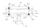
第1フレーム31および第2フレーム32の各々は、複数の孔を有している。後述の例示的な実施形態では、第1フレーム31は、第2フレーム32に対向する側の面上に4個の孔を有する。また第2フレーム32は、第1フレーム31に対向する側の面上に4個の孔を有する。
本実施形態では、紐状部材34-1および34-2は、それぞれ、第1フレーム31および第2フレーム32に設けられた孔を通る。具体的には、紐状部材34-1は第1フレーム31に設けられた孔36-1と、第2フレーム32に設けられた孔36-2とを通る。紐状部材34-2は第1フレーム31に設けられた孔36-3と、第2フレーム32に設けられた孔36-4とを通る。
紐状部材34-1および34-2の各端部には、紐状部材34-1および34-2が孔から脱落することを防止するための留め具38-1~38-4が設けられている。留め具38-1および38-3には、撮像装置20および支持装置30の全荷重がかかる。また、留め具38-2および38-4には、第2フレーム32、および撮像装置20の荷重がかかる。そのような荷重に耐えられるよう、紐状部材34-1と留め具38-1および38-2とは十分堅固に留められている。同様に、紐状部材34-2と留め具38-3および38-4とは十分堅固に留められている。なお、留め具38-1~38-4は、例えば金属製である。紐状部材と留め具とが十分堅固に固定できるのであれば、任意の素材および/または形状の留め具を採用し得る。留め具の形状の例は後に図11を参照しながら説明する。また、紐状部材とは別に留め具を設けることは必須ではない。例えば紐状部材を結んで結び目を作成し、結び目を上述の留め具の代わりに用いることもできる。結び目は、荷重がかけられた紐状部材が孔から脱落しない大きさ、形状および強度を有していればよい。結び目は樹脂等で補強され得る。
なお、孔36-1~36-4は第1フレーム31または第2フレーム32に設けられた貫通孔であることを想定している。しかしながら、上述の留め具によって紐状部材の脱落を防止できる場合には、例えば溝であってもよい。本明細書では、孔は溝を包含し得る。
2本の紐状部材を説明するために、枝番号を含む参照符号「34-1」および「34-2」を付した。本明細書では、特に具体的な紐状部材を説明する場合を除き、枝番号を含まない参照符号「34」によって任意の紐状部材を参照する場合がある。孔36-1~36-4についても同様に、枝番号を含まない参照符号「36」を用いて、任意の孔を表現する場合がある。留め具38-1~38-4についても同様である。
次に、図3A-図4Bを参照しながら、支持装置30に紐状部材34-1および34-2を採用することによる利点を説明する。なお、図3A-図4Bでは、無人ヘリコプタ1の記載、および、第1フレーム31および第2フレーム32が有する孔の記載は省略する。
まず、鉛直方向の動きに関する利点を説明する。
留め具と第1フレーム31、および/または、留め具と第2フレーム32は固定されていてもよいし、固定されていなくてもよい。いずれの場合であっても、ある条件下では第1フレーム31に入力された無人ヘリコプタ1からの振動が第2フレーム32に伝達されない。その条件とは、例えば無人ヘリコプタ1の飛行時に第1フレーム31と第2フレーム32とが相対的に近付く方向に動く場合である。
例えば、上昇中の無人ヘリコプタ1の動作が、上昇から急にホバリングに切り替わった場合を考える。第1フレーム31は無人ヘリコプタ1に取り付けられているため、第1フレーム31の挙動は無人ヘリコプタ1の挙動と一致する。一方、第2フレーム32は、上昇停止時の上向きの速さを初速として持って上昇を続け、第1フレーム31に相対的に近付く。
全ての留め具が、第1フレーム31および第2フレーム32の一方に固定されているとする。その場合、第1フレーム31と第2フレーム32とが相対的に近付くと、紐状部材34-1および34-2は撓む。図3Aは、撓んだ紐状部材34-1および34-2を模式的に示している。紐状部材34-1および34-2が撓むことにより、無人ヘリコプタ1から第1フレーム31に入力された高周波の振動の大部分、実質的に全ての高周波の振動、は、第2フレーム32には伝達されない。その結果、撮像装置20もまた高周波の振動の影響を受けない。
図3Aでは、第1フレーム31と第2フレーム32とは非平行である。その理由は、例えば無人ヘリコプタ1の姿勢に依存して、第1フレーム31が傾斜し得るからである。
留め具と第1フレーム31および/または第2フレーム32とが固定されていない場合を考える。図3Bは、全ての留め具と、第1フレーム31および第2フレーム32とが固定されていないときの、紐状部材34-1および34-2の挙動の一例を示している。無人ヘリコプタ1が下降して第1フレーム31と第2フレーム32とが互いに近付く場合、図示されるように、紐状部材34-1および34-2は、第1フレーム31の孔36-1および36-3(図2)の内部を摺動し、留め具38-1および/または留め具38-3が第1フレーム31から離れ得る。また、紐状部材34-1および34-2は、第2フレーム32の孔36-2および36-4(図2)の内部を摺動し、留め具38-2および/または留め具38-4が第2フレーム32から離れ得る。さらにこのとき、紐状部材34-1および34-2は撓み得る。場合によっては紐状部材34-1および34-2は撓みながら孔の中に入ることもあり得る。第1フレーム31に高周波の振動が入力されたとしても、紐状部材34-1および34-2から第2フレーム32等には伝達されない。
なお、留め具38-1および留め具38-2の一方がフレームに固定され、他方がフレームに固定されていなくてもよい。また、留め具38-3および留め具38-4の一方がフレームに固定され、他方がフレームに固定されていなくてもよい。例えば、留め具38-1および38-3と第1フレーム31とが固定されていない場合、または、留め具38-2および38-4と第2フレーム32とが固定されていない場合には、留め具が第1フレーム31または第2フレーム32から離れ、紐状部材34-1および34-2が撓み得る。その場合、第1フレーム31に入力された高周波の振動の大部分(実質的に全ての高周波の振動)は、紐状部材34-1、34-2を介して下方の第2フレーム32等に伝達されない。
高周波の振動が第2フレーム32に伝達されないため、撮像装置20もまた高周波の振動の影響を受けることはない。よって、静止画または動画のぶれを抑制できる。
また、本実施形態にかかる支持装置30を用いると、第1フレーム31および第2フレーム32が相対的に近付かない場合も振動の影響を低減可能である。例えば、無人ヘリコプタ1がホバリングを行っている場合である。ホバリング時には、鉛直方向(上下方向)の高周波の振動がランダムに発生すると仮定し得る。第1フレーム31に入力された鉛直方向(上下方向)の高周波の振動のうちの、下向きの振動は、第1フレーム31から第2フレーム32に伝達されない、または伝達されたとしても非常に小さいと考えられる。その理由は、下向きの振動が第1フレーム31に入力されたときは、微視的には第1フレーム31と第2フレーム32とが相対的に近付く方向に動いていると見なすことが可能だからである。その場合、図3Aおよび図3Bに関連して説明した例のとおり、第1フレーム31に入力された下向きの振動の大部分は、紐状部材34-1、34-2を介して下方の第2フレーム32等に伝達されず抑制される。
一方、第1フレーム31に入力された鉛直方向(上下方向)の高周波の振動のうちの、上向きの振動は、第1フレーム31が紐状部材34-1、34-2を介して第2フレーム32を引き上げる力を生じさせる。よって、その上向きの振動は第1フレーム31から第2フレーム32に伝達され得る。
上述の説明から理解されるように、ホバリング時には、第1フレーム31から第2フレーム32に伝達される高周波の振動を少なくとも概ね半減させることができる。
なお、無人ヘリコプタ1が上昇する場合には、紐状部材34-1および34-2は伸び切り、かつ、各留め具は第1フレーム31または第2フレーム32と接触する。したがって、第1フレーム31に入力された高周波の振動は、第2フレーム32を介して撮像装置20に伝達され得る。
次に、無人ヘリコプタ1から第1フレーム31に入力される水平方向の振動に関する利点を説明する。当初は、第1フレーム31は無人ヘリコプタ1に取り付けられ、第2フレーム32は紐状部材34-1および34-2を介して第1フレーム31の真下に吊り下げられているとする。
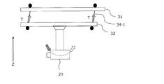
図4Aおよび図4Bは、第1フレーム31に伝えられた水平方向の揺れ(振動)が、紐状部材34-1および34-2によって第2フレーム32に伝達される様子を示している。より具体的には、図4Aおよび図4Bは、紐状部材34-1および34-2を介して伝達される力によって、第2フレーム32が垂直面内の矢印の方向への回転運動を行う様子を示している。
いま、無人ヘリコプタ1から第1フレーム31に水平方向の振動が与えられた場合を考える。無人ヘリコプタ1から第1フレーム31へは、水平方向にランダムに発生する高周波の揺れが伝達される。つまり、第1フレーム31は任意の方向に高周波で揺れる。ただし高周波の揺れの振幅は十分小さい。高周波の揺れは、エンジンまたはメインロータ5の高速回転に起因して発生しており、大きくても数センチメートル程度である。第1フレーム31の揺れは、紐状部材34-1および34-2を介して第2フレーム32に伝達される。第2フレーム32が紐状部材34-1および34-2から受ける力Tはいわゆる張力であり、その方向は、第2フレーム32が紐状部材34-1および34-2から引っ張られる方向である。第1フレーム31が任意の方向に高周波で揺れることにより、力Tの方向も高周波で変化する。よって力Tの鉛直方向(Z軸方向)の分力(鉛直上向き)は高周波で微小に変動し続ける。ただし、第2フレーム32および撮像装置20が受ける鉛直下向きの重力と比較して、高周波の変動は十分小さい。そのため、力Tの鉛直方向(Z軸方向)の分力は常に、第2フレーム32および撮像装置20が受ける重力と釣り合い続ける。実質的には、鉛直方向に関する力の釣り合いに変化はない。
力Tの水平方向の成分、すなわちZ軸に垂直な平面(水平面)方向の成分は、Z軸を含む平面(垂直面)内で、第2フレーム32および撮像装置20を振動させる。ここで言う「振動」とは、垂直面内での振動を意味する。垂直面内での振動の典型例は垂直面内の振り子運動(回転運動)である。ただし、無人ヘリコプタ1から第1フレーム31へは水平方向の振動が絶え間なく与えられるため、本実施形態で想定する垂直面内での振動は、単振り子のような周期的な振動とは異なることに留意されたい。
無人ヘリコプタ1から第1フレーム31に加えられる水平方向の高周波の振動について、その振幅が、最大振幅の大きさを規定する、第1フレーム31側の紐状部材34の支点(例えば留め具)から、第2フレーム32側の紐状部材34の支点(例えば留め具)までの紐状部材34の長さよりも十分小さい場合は、第1フレーム31以下の質量と紐状部材34の長さで決まる固有振動数の振動は伝達される。それ以外の振動は伝達されない。例えば、紐状部材34の長さが2cm程度かそれ以上であれば、約20Hz以下の垂直面内での振動が伝達される。この程度の振動は、例えば撮像装置20に搭載され得る手振れ補正機能、または、ジンバル(後述)の手振れ補正機能で補正され得る。これにより、無人ヘリコプタ1から入力される高周波の振動が撮像装置20の撮影結果に与える影響を大きく低減できる。上述の説明では、紐状部材34の支点として「留め具」を例示したが、留め具ではない場合もあり得る。例えば、振動が大きくなった場合には、第1フレーム31の、第2フレーム32と対向する側の面の孔の縁が、第1フレーム31側の支点になることもあり得る。同様に、第2フレーム32の、第1フレーム31と対向する側の面の孔の縁が、第2フレーム32側の支点になることもあり得る。
なお、紐状部材34-1および34-2が伸縮する場合には、水平方向の振動は概ね抑制される。例えば、第2フレーム32が紐状部材34-1および34-2から同位相で引っ張られる場合、紐状部材34-1および34-2が伸縮することにより、水平方向の振動はやがて収束する。
以下、上述の支持装置30の実施形態にかかる構成を説明する。以下の説明では、図2等に示される支持装置30の構成要素と同じ構成要素には同じ参照符号を付し、その説明は省略する場合がある。また、記載の簡潔さのため、参照した図面に記載された構成要素と同じ構成要素であっても参照符号を付さない場合がある。
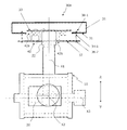
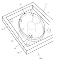
図5Aおよび図5Bは、例示的な支持装置30Aの正面図および側面図である。また図6は、支持装置30Aの上方から下方を見たときの部分斜視図である。記載の便宜上、図6には第2フレーム32は記載されていない。破線は第1フレーム31等を透過したときのエッジを表している。
図5Aおよび図5Bに示す第1フレーム31および第2フレーム32の形状は図2等と異なっている。例えば第1フレーム31および第2フレーム32はそれぞれ開口42aおよび42bを有している。しかしながら、紐状部材34-1、34-2を通すための空間(孔、溝等)を有していれば第1フレーム31および第2フレーム32の形状は種々取り得る。なお、無人ヘリコプタ1に取り付けるための構成の有無は第1フレーム31の必須ではない。
例示的な実施形態では、支持装置30Aは、第1フレーム31および第2フレーム32に加え、第3フレーム33を有している。そして、上述した図2に記載の支持装置30では、第2フレーム32に直接取り付けられていたアーム22が、第3フレーム33に直接取り付けられている。さらに棒状であったアーム22は、概ねコの字形状である(図5B)。以下では、これらの相違点を主として説明する。なお、第2フレーム32が紐状部材34-1および34-2を介して第1フレーム31から吊り下げられている点は、図2等の構成と同じである。
まず、第3フレーム33は、複数のダンパー、例えばダンパー40、を介して第2フレーム32と接続され、さらにアーム22とは直接接続されている。第3フレーム33に接続されたアーム22は下方に伸びて、第1フレーム31の開口42a、第2フレーム32の開口42を順に通る。アーム22は、ジンバル10を構成する要素の一つである。アーム22の下方に存在するジンバル10は、直交する3本の軸X1~X3を中心として撮像装置20を回転させることが可能な回転台の一種である。軸X3に設けられたマウントに撮像装置20が固定されている。これにより、撮像装置20の向きを概ね一定に保つことができる。ジンバル10を設けることにより、撮像装置20が有するぶれ補正機構による補正をより効果的に行うことができる。よってぶれを大きく低減した撮影を行うことができる。ジンバルを介して、撮像装置20は第3フレーム33、第2フレーム32および第1フレーム31と間接的に固定される。
ダンパーは、振動エネルギーを減衰または消滅させて衝撃または振動の振幅を軽減する装置である。以下、ダンパー40を例示的に説明する。他のダンパーもダンパー40と同様の機能、配置および構成を有するが説明は省略する。
図5Aおよび図5Bに明確に示されているように、ダンパー40は、下側の第2フレーム32と上側の第3フレーム33との間に配置され、第2フレーム32から入力される振動を減衰させる。
上述のように、本開示では、無人ヘリコプタ1が上昇する場合には、紐状部材を設けたとしても鉛直方向の高周波の振動を半減はできても完全には減衰させることができない。その場合、無人ヘリコプタ1から第1フレーム31に与えられた高周波の振動が第2フレーム32に伝達され得る。そして第2フレーム32、第3フレーム33、ジンバル10および撮像装置20には、鉛直下向きおよび上向きの固有振動数の振動が伝達され得る。このときの振動は、主としてジンバル10および撮像装置20の重心を中心とした振動(回転運動)である。
しかしながらダンパー40を設けることにより、鉛直下向きおよび上向きに加えられる振動の速度に応じた減衰力が、速度の方向と反対の方向に第2フレーム32に加えられる。これにより、より効果的に鉛直方向の振動をさらに減衰させることができる。その結果、第2フレーム32から入力された、鉛直方向の高周波の振動は大幅に減衰され、または実質的に除去され、第3フレーム33に伝達される振動を大幅に抑制できる。なお、無人ヘリコプタ1が上昇する場合以外の場合でも、第2フレーム32に僅かに振動が伝達される場合が想定され得る。そのような振動もまたダンパー40によって低減されるため、第3フレーム33への伝達を抑制できる。
図7は、本実施形態の変形例にかかる支持装置30Bの上面透過図である。支持装置30Bと上述の支持装置30Aとの相違点は、新たに複数のダンパー44を有する点である。複数のダンパー44は、第1フレーム31と第2フレーム32との間に設けられて水平方向の振動を軽減する。図7における水平方向とは、図面左上に示す2本の直交する矢印が張る平面上の任意の方向である。他の構成は支持装置30Aと同じである。
複数のダンパー44を設けることにより、垂直面内の振動とともに発生する水平面内での振動を減衰させる減衰力が、水平面内の変動方向と反対の方向に第2フレームに加えられる。これにより、より効果的に水平方向の振動を減衰させることができる。
鉛直方向および/または水平方向の振動を減衰させるダンパーを設けることにより、鉛直方向および/または水平方向の振動をより迅速に減衰させることができる。
ダンバーの粘性係数を高めた場合、ダンパーを介して振動がそのまま一方のフレームから他方のフレームに伝達され得る。そのため、ダンパーの粘性係数は高すぎない方が好適である。なお、粘性係数は種々の条件によって決定し得る。当業者であれば、例えばダンパーの大きさ、重さ、想定される入力の範囲等に応じて、適切な粘性係数を決定し得る。
次に、図8~10を参照しながら、振動に伴う水平方向の回転を説明する。留め具として金属球を用いるとする。ただし紐状部材34の脱落を防止できる限り、留め具は金属球である必要はない。
図8は、留め具である金属球46を有する紐状部材34の例を示している。記載の便宜上、2本の紐状部材および2個の金属球46にのみ参照符号を付しているが、図示された4本の紐状部材および4個の金属球はいずれも同じである。また、第2フレーム32の下面においても、紐状部材34は金属球46を有していてもよい。
図8に示す例では、金属球46の大きさは、第1フレーム31に開口した孔の各径よりも大きい。より具体的には、孔の開口を含む平面、例えば第1フレーム31の表面、に平行な平面に投影した金属球の径は、開口した孔の各径よりも大きい。上述した関係は、留め具38-1~38-4(図2等)についても同様である。これにより、紐状部材が孔から脱落することを防止することができる。
また図8では、第2フレーム32は、4隅に設けられた4つの孔(例えば孔36-2、36-4)を通る4本の紐状部材34によって支持されている。第2フレーム32を4箇所で支持することにより、第2フレーム32は平面的に安定して支持される。図示されるように、4つの支持点は第2フレーム32の4隅に設けられており、平面視で矩形状に配置されている。このような配置により、孔の配置の調整が容易である。これにより、孔を有する第2フレーム32をより簡単に製造することができる。
図9は、第1フレーム31の孔36と紐状部材34との関係を示している。(a)は、金属球46が孔36の開口部周辺の第1フレーム31表面で止まることによって、紐状部材34が孔36から抜け落ちることを防いでいる状態を示している。このとき、紐状部材34-1が伸びきっている。(b)は、紐状部材34が孔36内を摺動して金属球46を押し上げた状態を示している。このとき、紐状部材34-1は若干撓んでいることが理解される。(b)の状態は、図3Bに示す状態に対応している。
(a)の状態では、第1フレーム31に伝えられた高周波の振動が、金属球46および紐状部材34を介してそのまま下方に伝達され得る。このとき、紐状部材34の他方の端部、すなわち第2フレーム32の下面側に設けられた金属球が第2フレーム32と接触していると、振動が第2フレーム32に伝達され得る。
一方、(b)の状態では、金属球46が第1フレーム31の表面から距離D(>0)だけ離れている。そのため、第1フレーム31に伝えられた高周波の振動は金属球46および紐状部材34を介して下方に伝わらない。孔36の内面または開口と紐状部材34とが接触していたとしても、紐状部材34が撓んでいることにより、紐状部材34を伝わる振動は大幅に低減され、または遮断される。
なお、第2フレーム32についても同様である。金属球46が第2フレーム32の表面と接触しているか否かに応じて、振動が第2フレーム32に伝達されるか否かが変わり得る。
これまでの説明では、第2フレーム32は4本の紐状部材34によって4点で支持されていた。ただし「4本の紐状部材34」は、物理的に4本である必要はなく、少なくとも1本あればよい。
図10は、1本の紐状部材50を引き回すことにより、見かけ上4本の紐状部材によって第2フレーム32を支持している例を示している。これまでの説明と同様、第1フレーム31および第2フレーム32には複数の孔が設けられている。紐状部材50は、各孔の中を摺動可能である。図10の例のように、少なくとも1本の紐状部材50であっても、第2フレーム32を複数点で平面的に安定して支持することができる。なお図10では、留め具または結び目の記載は省略している。なお、紐状部材50を第1フレーム31および/または第2フレーム32に固定してもよい。
また、第2フレーム32を4点で支持することも必須ではなく、3点以上あれば第2フレーム32を安定して支持することができる。ただし全ての点が1本の直線上に配置されている場合は除く。
次に、留め具の形状および紐状部材の引き回しに関する変形例を説明する。
図11は、金属製の留め具38-1~38-4と、紐状部材である金属製のワイヤー34-1および34-2とを有する例示的な支持装置30Eの側面を模式的に示している。留め具38-1~38-4は円柱状の分銅型である。留め具38-1および38-2は、ワイヤー34-1によって互いに接続されている。留め具38-3および38-4は、ワイヤー34-2によって互いに接続されている。この変形例では、留め具38-1および38-2はともに第1フレーム31および第2フレーム32の間に対向して設けられている。
留め具38-1と接続されたワイヤー34-1は、第1フレーム31に設けられた孔36-5を通って第1フレーム31の-Z側の面から+Z側の面に到達し、+Z側の面上を孔36-1まで伸びる。その後ワイヤー34-1は、孔36-1を経て再び第1フレーム31の-Z側の面に伸び、そのまま第2フレーム32の+Z側の面から孔36-2に入って-Z側の面に到達する。ワイヤー34-1は、第2フレーム32の-Z側の面上を孔36-6まで伸び、孔36-6を通って第2フレーム32の+Z側の面に到達する。そしてワイヤー34-1は留め具38-2と接続される。図示されるように、留め具38-3および38-4と接続されたワイヤー34-2も全く同様に接続されるため、説明は省略する。
図11の構成によれば、留め具38の振動によるずれの影響を大きく低減できる。留め具38の位置が変化しにくいため、金属製のワイヤー34の径が孔36の径より小さい場合であってもワイヤー34を孔36の中の一定の位置に保持させることができる。仮に留め具38の位置がXY平面上のいずれかの方向にずれたとしても、ワイヤー34の支点の位置は概ね維持される。よってワイヤー34を孔36の中の一定の位置に保持させることができる。
これまで説明したように、紐状部材(ワイヤー)34は化学繊維製であってもよいし、金属製であってもよい。本実施形態においては、第1フレーム31と第2フレーム32との間において、紐状部材34の長さは一定である。つまり、紐状部材34の長さは実質的には変化しない。そのため、当該紐状部材34は、第1フレーム31と第2フレーム32とが互いに離れる方向への相対的な移動を規制する。一方、紐状部材34は可撓性を有している。そのため、当該紐状部材34は、第1フレーム31と第2フレーム32とが互いに近付く方向へ相対的に移動すると撓むため、第1フレーム31と第2フレーム32とは、紐状部材34-1の長さよりも近付くことはあり得る。
本発明の実施形態による、撮像装置20の支持装置30、30A~30Eは、回転翼機1に取り付けられる第1フレーム31と、撮像装置20が直接的または間接的に取り付けられる第2フレーム32と、第2フレーム32を第1フレーム31から吊り下げる少なくとも1本の紐状部材34であって、第2フレーム32を少なくとも3点で平面的に支持する、少なくとも1本の紐状部材34とを備えている。
本発明の実施形態による支持装置30および30aでは、支持装置30および30aが回転翼機1に取り付けられたとき、回転翼機1から第1フレーム31に加えられる水平方向の振動および/または鉛直方向の振動の影響は少なくとも1本の紐状部材34によって低減される。これにより、撮像装置20は高周波の振動を低減して撮影を行うことができる。
ある実施形態において、少なくとも1本の紐状部材34は、第1フレーム31と第2フレーム32とが互いに離れる方向への相対的な移動を規制し、第1フレーム31と第2フレーム32とが互いに近付く方向への相対的な移動を許容する。
少なくとも1本の紐状部材34は、第1フレーム31と第2フレーム32とが互いに近付く方向への相対的な移動を許容する。より具体的には、ある実施形態において、前記第1フレームと前記第2フレームとの間において、前記少なくとも1本の紐状部材は一定の長さを有しており、それにより、前記第1フレームと前記第2フレームとが互いに離れる方向への相対的な移動を規制し、前記少なくとも1本の紐状部材は可撓性を有しており、それにより、前記第1フレームと前記第2フレームとが互いに近付く方向への相対的な移動を許容する。例えば少なくとも1本の紐状部材が可撓性を有しており、撓むことにより、第1フレーム31と第2フレーム32とは互いに近付く方向への相対的な移動が可能になる。これにより、第1フレーム31から第2フレーム32に伝達される振動を低減できる。
ある実施形態において、少なくとも1本の紐状部材34の素材は繊維である。繊維であることにより、少なくとも1本の紐状部材34は細く、しなやかであり、柔軟に変形し得る。
ある実施形態において、当該繊維は化学繊維である。化学繊維は人工的に作製され得るため、紐状部材の強度および柔軟性を所望の仕様に調整できる。
ある実施形態において、第1フレーム31は、第2フレーム32に対向する位置に少なくとも1つの孔36を有しており、少なくとも1本の紐状部材34は少なくとも1つの孔36を通る。紐状部材34の径が孔36の径よりも小さいため、柔軟な紐状部材34を利用できる。
ある実施形態において、少なくとも1本の紐状部材34は、少なくとも1つの孔36の径よりも大きい径を有する部材(留め具38)または結び目を有している。留め具38または結び目は、少なくとも1つの孔36に関して第2フレーム32と反対側に位置する。これにより、少なくとも1本の紐状部材34の脱落を防止しながら、第2フレーム32を吊り下げることができる。
ある実施形態において、少なくとも1本の紐状部材は、前記少なくとも1つの孔を摺動可能である。これにより、第1フレーム31と第2フレーム32とは互いに近付く方向に移動できる。
ある実施形態において、第2フレーム32は、第1フレーム31に対向する位置に3個以上の孔36を有しており、少なくとも1本の紐状部材34が当該3個以上の孔36の各々を通る。これにより、第2フレーム32を少なくとも3点で平面的に支持することができる。
ある実施形態において、紐状部材34は、当該3個以上の孔36の各径よりも大きい径を有する部材(留め具38)または結び目を有しており、当該部材または結び目は、3個以上の孔36の各々に関して第1フレームと反対側に位置する。これにより、第1フレーム31と第2フレーム32とは互いに離れる方向への相対的な移動が規制され、その一方、互いに近付く方向への相対的な移動は許容される。
ある実施形態において、少なくとも1本の紐状部材34は、当該3個以上の孔36の各々を摺動可能である。これにより、第1フレーム31と第2フレーム32とは互いに近付く方向に移動できる。
ある実施形態において、第2フレーム32は、第1フレーム31に対向する位置に4個の孔を有する。少なくとも1本の紐状部材34は、3個の孔よりも多くの孔を摺動可能であり、また少なくとも4点で第2フレーム32を平面的に支持する。3点で支持する場合と比較して、4点で支持する方が第2フレーム32を安定して支持し得る。
ある実施形態において、第2フレーム32の4個の孔36は、平面視で矩形状に配置されている。矩形状に配置することにより、各孔の配置の調整が容易である。これにより、孔を有する第2フレームをより簡単に製造することができる。
ある実施形態において、第2フレーム32を第1フレーム31から吊り下げたときの方向を鉛直方向と呼び、鉛直方向に鉛直な方向を水平方向と呼ぶとき、支持装置は、第1フレーム31と第2フレーム32との間に、鉛直方向の振動を減衰させるダンパー40、および/または、水平方向の振動を減衰させるダンパー44をさらに備えている。ダンパーを設けることにより、鉛直方向および/または水平方向の振動をより迅速に減衰させることができる。
ある実施形態において、支持装置30Aは第1フレーム31と第2フレーム32との間に、第2フレーム32と機械的に接続され、撮像装置が取り付けられる第3フレーム33をさらに備え、支持装置30Bは、第1フレーム31と第2フレーム32との間に、水平方向の振動を減衰させる第1ダンパー44を有し、第1フレーム31と第2フレーム32との間に、鉛直方向の振動を減衰させる第2ダンパー40を有している。これにより、水平方向および鉛直方向の振動を減衰させることができる。
本発明の実施形態による回転翼機1は、上述のいずれかの支持装置30、30A~30Eと、回転翼(メインロータ)5と、回転翼5を回転させる原動機と、原動機を収容する機体4と、水平方向および鉛直方向に関するぶれ補正を行うことが可能なぶれ補正機構を有する撮像装置20とを備え、支持装置30、30A~30Eの第1フレーム31と機体4とが固定されており、支持装置30、30A~30Eの第2フレーム32と撮像装置20とが直接的または間接的に固定されている。上述の支持装置を用いることにより、無人ヘリコプタ1から支持装置30、30A~30Eの第2フレーム32に伝達される振動を抑制できる。これにより、撮像装置20は高周波の振動を低減して撮影を行うことができる。
本発明による支持装置は、ヘリコプタ等の回転翼機のような、高周波の振動が発生する移動体に撮像装置を搭載する際に有用である。
1 無人ヘリコプタ(回転翼機)、 4 機体、 5 回転翼(メインロータ)、 10 ジンバル、 20 撮像装置、 22 アーム、 30、30A~30D 支持装置、 31 第1フレーム、 32 第2フレーム、 33 第3フレーム、 34、34-1~34-4 紐状部材、 36、36-1~36-4、36-5~36-8 孔、 38-1~38-4 留め具、 40、44 ダンパー、 46 留め具(金属球)、 50 紐状部材
Claims (17)
- 回転翼機に取り付けられる第1フレームと、
撮像装置が直接的または間接的に取り付けられる第2フレームと、
前記第2フレームを前記第1フレームから吊り下げる少なくとも1本の紐状部材であって、前記第2フレームを少なくとも3点で平面的に支持する、少なくとも1本の紐状部材と
を備えた、前記撮像装置の支持装置。 - 前記少なくとも1本の紐状部材は、前記第1フレームと前記第2フレームとが互いに離れる方向への相対的な移動を規制し、前記第1フレームと前記第2フレームとが互いに近付く方向への相対的な移動を許容する、請求項1に記載の支持装置。
- 前記第1フレームと前記第2フレームとの間において、
前記少なくとも1本の紐状部材は一定の長さを有しており、それにより、前記第1フレームと前記第2フレームとが互いに離れる方向への相対的な移動を規制し、
前記少なくとも1本の紐状部材は可撓性を有しており、それにより、前記第1フレームと前記第2フレームとが互いに近付く方向への相対的な移動を許容する、請求項2に記載の支持装置。 - 前記少なくとも1本の紐状部材の素材は繊維である、請求項1から3のいずれかに記載の支持装置。
- 前記繊維は化学繊維である、請求項4に記載の支持装置。
- 前記第1フレームは、前記第2フレームに対向する位置に少なくとも1つの孔を有しており、
前記少なくとも1本の紐状部材は前記少なくとも1つの孔を通る、請求項1から5のいずれかに記載の支持装置。 - 前記少なくとも1本の紐状部材は、前記少なくとも1つの孔の径よりも大きい径を有する部材または結び目を有しており、
前記部材または結び目は、前記少なくとも1つの孔に関して前記第2フレームと反対側に位置する、請求項6に記載の支持装置。 - 前記少なくとも1本の紐状部材は、前記少なくとも1つの孔を摺動可能である、請求項6または7に記載の支持装置。
- 前記第2フレームは、前記第1フレームに対向する位置に3個以上の孔を有しており、
前記少なくとも1本の紐状部材が前記3個以上の孔の各々を通ることにより、前記第2フレームを少なくとも3点で平面的に支持する、請求項6から8のいずれかに記載の支持装置。 - 前記少なくとも1本の紐状部材は、前記3個以上の孔の各径よりも大きい径を有する部材または結び目を有しており、
前記部材または結び目は、前記3個以上の孔の各々に関して前記第1フレームと反対側に位置する、請求項9に記載の支持装置。 - 前記少なくとも1本の紐状部材は、前記3個以上の孔の各々を摺動可能である、請求項9または10に記載の支持装置。
- 前記第2フレームは、前記第1フレームに対向する位置に4個の孔を有する、請求項8または9に記載の支持装置。
- 前記第2フレームの前記4個の孔は、平面視で矩形状に配置されている、請求項12に記載の支持装置。
- 前記第2フレームを前記第1フレームから吊り下げたときの方向を鉛直方向と呼び、前記鉛直方向に鉛直な方向を水平方向と呼ぶとき、
前記第1フレームと前記第2フレームとの間に、前記鉛直方向の振動を減衰させるダンパー、および/または、前記水平方向の振動を減衰させるダンパーをさらに備えた、請求項1から13のいずれかに記載の支持装置。 - 前記第1フレームと前記第2フレームとの間に、前記第2フレームと機械的に接続され、前記撮像装置が取り付けられる第3フレームをさらに備え、
前記第1フレームと前記第2フレームとの間に、前記水平方向の振動を減衰させる第1ダンパーを有し、
前記第2フレームと前記第3フレームとの間に、前記鉛直方向の振動を減衰させる第2ダンパーを有する、請求項14に記載の支持装置。 - 回転翼機であって、
請求項1から15のいずれかに記載の支持装置と、
回転翼と、
前記回転翼を回転させる原動機と、
前記原動機を収容する機体と、
水平方向および鉛直方向に関するぶれ補正を行うことが可能なぶれ補正機構を有する撮像装置と
を備え、
前記支持装置の前記第1フレームと前記機体とが固定されており、
前記支持装置の前記第2フレームと前記撮像装置とが直接的または間接的に固定されている、回転翼機。 - ジンバルをさらに備え、
前記第2フレームと前記撮像装置とは前記ジンバルを介して間接的に固定されている、請求項16に記載の回転翼機。
Applications Claiming Priority (2)
| Application Number | Priority Date | Filing Date | Title |
|---|---|---|---|
| JP2018-247690 | 2018-12-28 | ||
| JP2018247690 | 2018-12-28 |
Publications (1)
| Publication Number | Publication Date |
|---|---|
| WO2020138215A1 true WO2020138215A1 (ja) | 2020-07-02 |
Family
ID=71129577
Family Applications (1)
| Application Number | Title | Priority Date | Filing Date |
|---|---|---|---|
| PCT/JP2019/050938 Ceased WO2020138215A1 (ja) | 2018-12-28 | 2019-12-25 | 撮像装置の支持装置、該支持装置を有する回転翼機 |
Country Status (1)
| Country | Link |
|---|---|
| WO (1) | WO2020138215A1 (ja) |
Cited By (1)
| Publication number | Priority date | Publication date | Assignee | Title |
|---|---|---|---|---|
| CN114906319A (zh) * | 2022-05-07 | 2022-08-16 | 北京航天长城卫星导航科技有限公司 | 一种长距离等高地表用无人机自主巡检装置 |
Citations (2)
| Publication number | Priority date | Publication date | Assignee | Title |
|---|---|---|---|---|
| JPS56167338U (ja) * | 1980-05-15 | 1981-12-11 | ||
| JP2015090043A (ja) * | 2013-11-07 | 2015-05-11 | 前澤工業株式会社 | ゲート調査装置 |
-
2019
- 2019-12-25 WO PCT/JP2019/050938 patent/WO2020138215A1/ja not_active Ceased
Patent Citations (2)
| Publication number | Priority date | Publication date | Assignee | Title |
|---|---|---|---|---|
| JPS56167338U (ja) * | 1980-05-15 | 1981-12-11 | ||
| JP2015090043A (ja) * | 2013-11-07 | 2015-05-11 | 前澤工業株式会社 | ゲート調査装置 |
Cited By (1)
| Publication number | Priority date | Publication date | Assignee | Title |
|---|---|---|---|---|
| CN114906319A (zh) * | 2022-05-07 | 2022-08-16 | 北京航天长城卫星导航科技有限公司 | 一种长距离等高地表用无人机自主巡检装置 |
Similar Documents
| Publication | Publication Date | Title |
|---|---|---|
| CN107241912B (zh) | 竖向增稳机构及云台装置和拍摄设备 | |
| CN205534966U (zh) | 竖向增稳机构、云台装置及拍摄设备 | |
| CN103939718B (zh) | 增稳云台及其控制方法和携带所述增稳云台的无人飞行器 | |
| US9605795B2 (en) | Electronic stabilizing system for a camera | |
| WO2017179160A1 (ja) | 無人航空機用防振構造 | |
| US10047905B2 (en) | Gimbal and unmanned aerial vehicle including the same | |
| JP2018534490A (ja) | 搭載物を安定させる安定化装置 | |
| KR101919919B1 (ko) | 영상 촬영을 위한 무진동 짐벌 장치 | |
| WO2019090755A1 (zh) | 运动传感器组件及无人机 | |
| US20160348830A1 (en) | Stabilized platform for camera | |
| CN101774431A (zh) | 无人机球形吊挂式二自由度云台 | |
| CN108803202A (zh) | 一种拍摄组件 | |
| US12146609B2 (en) | Load-stabilizing apparatus | |
| CN107636918A (zh) | 信号传输件、云台以及可移动装置 | |
| KR20190116748A (ko) | 폴딩 가능한 랜딩기어 및 이를 구비한 무진동 짐벌 장치 | |
| JP2020011703A (ja) | 全方向ケーブルカム | |
| JP7383213B2 (ja) | 回転機構、飛行体、積載物の姿勢制御装置、方法 | |
| JPH06125490A (ja) | カメラ防振装置 | |
| WO2020138215A1 (ja) | 撮像装置の支持装置、該支持装置を有する回転翼機 | |
| CN113826377B (zh) | 云台的控制方法及装置、云台以及可移动平台 | |
| KR102472035B1 (ko) | 스태빌라이저를 구비한 짐벌 장치 | |
| US10473263B2 (en) | Gimbal viration isolator | |
| KR102155649B1 (ko) | 임무장비 설치용 짐벌 | |
| CN207045655U (zh) | 机臂组件、机架及无人飞行器 | |
| KR20190001084A (ko) | 이중 폴딩 랜딩기어 및 이를 구비한 무진동 짐벌 장치 |
Legal Events
| Date | Code | Title | Description |
|---|---|---|---|
| 121 | Ep: the epo has been informed by wipo that ep was designated in this application |
Ref document number: 19904852 Country of ref document: EP Kind code of ref document: A1 |
|
| NENP | Non-entry into the national phase |
Ref country code: DE |
|
| 122 | Ep: pct application non-entry in european phase |
Ref document number: 19904852 Country of ref document: EP Kind code of ref document: A1 |
|
| NENP | Non-entry into the national phase |
Ref country code: JP |