WO2020138141A1 - エアスプリング係止構造 - Google Patents
エアスプリング係止構造 Download PDFInfo
- Publication number
- WO2020138141A1 WO2020138141A1 PCT/JP2019/050759 JP2019050759W WO2020138141A1 WO 2020138141 A1 WO2020138141 A1 WO 2020138141A1 JP 2019050759 W JP2019050759 W JP 2019050759W WO 2020138141 A1 WO2020138141 A1 WO 2020138141A1
- Authority
- WO
- WIPO (PCT)
- Prior art keywords
- shaft
- shaft insertion
- insertion hole
- air spring
- seated state
- Prior art date
- Legal status (The legal status is an assumption and is not a legal conclusion. Google has not performed a legal analysis and makes no representation as to the accuracy of the status listed.)
- Ceased
Links
Images





Classifications
-
- B—PERFORMING OPERATIONS; TRANSPORTING
- B62—LAND VEHICLES FOR TRAVELLING OTHERWISE THAN ON RAILS
- B62D—MOTOR VEHICLES; TRAILERS
- B62D24/00—Connections between vehicle body and vehicle frame
- B62D24/02—Vehicle body, not intended to move relatively to the vehicle frame, and mounted on vibration absorbing mountings, e.g. rubber pads
-
- B—PERFORMING OPERATIONS; TRANSPORTING
- B62—LAND VEHICLES FOR TRAVELLING OTHERWISE THAN ON RAILS
- B62D—MOTOR VEHICLES; TRAILERS
- B62D33/00—Superstructures for load-carrying vehicles
- B62D33/06—Drivers' cabs
- B62D33/063—Drivers' cabs movable from one position into at least one other position, e.g. tiltable, pivotable about a vertical axis, displaceable from one side of the vehicle to the other
- B62D33/067—Drivers' cabs movable from one position into at least one other position, e.g. tiltable, pivotable about a vertical axis, displaceable from one side of the vehicle to the other tiltable
-
- F—MECHANICAL ENGINEERING; LIGHTING; HEATING; WEAPONS; BLASTING
- F16—ENGINEERING ELEMENTS AND UNITS; GENERAL MEASURES FOR PRODUCING AND MAINTAINING EFFECTIVE FUNCTIONING OF MACHINES OR INSTALLATIONS; THERMAL INSULATION IN GENERAL
- F16F—SPRINGS; SHOCK-ABSORBERS; MEANS FOR DAMPING VIBRATION
- F16F9/00—Springs, vibration-dampers, shock-absorbers, or similarly-constructed movement-dampers using a fluid or the equivalent as damping medium
- F16F9/02—Springs, vibration-dampers, shock-absorbers, or similarly-constructed movement-dampers using a fluid or the equivalent as damping medium using gas only or vacuum
- F16F9/04—Springs, vibration-dampers, shock-absorbers, or similarly-constructed movement-dampers using a fluid or the equivalent as damping medium using gas only or vacuum in a chamber with a flexible wall
- F16F9/05—Springs, vibration-dampers, shock-absorbers, or similarly-constructed movement-dampers using a fluid or the equivalent as damping medium using gas only or vacuum in a chamber with a flexible wall the flexible wall being of the rolling diaphragm type
Definitions
- the present disclosure relates to a vehicle air spring locking structure in which an air spring is interposed between an upper structure and a lower structure.
- a frame side bracket is attached to a chassis frame of a vehicle, a cab side bracket is attached to a cab, a frame side bracket and a cab side bracket are connected by a link arm, and a cab side bracket and a link arm are connected to each other.
- a cab suspension structure with air springs is described.
- the air spring includes a bellows that forms an air chamber and can be contracted, a fixed portion that is provided on the upper end side of the bellows and is fixed to the cab side bracket, and a seating portion that is provided on the lower end side of the bellows and that engages with the link arm.
- a female screw portion is formed on the seating portion, and the shaft portion is screwed into the female screw portion.
- the air spring functions as an air spring that reduces the impact transmitted from the link arm to the cab side bracket by filling the bellows with air.
- the upper surface of the link arm has a through hole through which the shaft of the air spring is inserted.
- the shaft portion includes a male screw portion screwed into the female screw portion of the seating portion, and a shaft portion main body having an outer diameter larger than that of the male screw portion.
- a step surface is formed at the boundary between the male screw portion and the shaft body, and the step surface is pressed against the lower end surface of the seat portion by tightening the shaft portion.
- the bellows When the air pressure inside the bellows decreases, the bellows may contract and the seating portion may rise until the stopper contacts the fixed portion. In this state, the seat portion is the farthest from the link arm. At this time, assuming that the distance between the seating portion and the link arm is t 2 , the length dimension L of the shaft body is set to be larger than this t 2 . Therefore, even in this case, the lower end portion of the shaft portion is still inserted into the through hole of the link arm, and the shaft portion is prevented from coming off the link arm.
- Patent Document 1 when the protruding height of the shaft portion from the seat portion (the length of the shaft body) is increased, the lower end surface of the seat portion is pressed against the upper surface of the link arm (seat state). Since the gap between the lower end of the shaft portion and the frame-side bracket is reduced, the maximum protruding height of the shaft portion is naturally limited to less than the length that interferes with the frame-side bracket. Therefore, depending on the layout of the vehicle, the protruding height of the shaft cannot be sufficiently secured, and the shaft is inserted through the through hole until the seat is most separated from the link arm (air spring locked state). Can be difficult to maintain.
- the present disclosure aims to provide an air spring locking structure capable of reliably preventing the release of the air spring locking state while suppressing an increase in the protruding height of the shaft portion.
- the first aspect of the present disclosure is a seated state in which an air spring is fixed to an upper structure, and a seat portion at a lower portion of the air spring is placed on a spring support portion on the lower structure side.
- the air spring is interposed between the upper structure and the lower structure to elastically support the upper structure, and the air spring moves upward from the seated state together with the upper structure, so that the seating portion moves upward from the spring support portion.
- the seating portion and the spring supporting portion are separated from each other, and one of the seating portion and the spring supporting portion projects from the first abutting portion, the first facing surface that intersects with the vertical direction in the seated state, and the first facing surface. And a shaft portion extending in the vertical direction.
- the other one of the seating portion and the spring support portion is a second contact surface that abuts the first contact portion in a seated state, and a second facing surface that intersects with the up-down direction in the seated state and that faces away from the first facing surface. And a shaft movement restricting portion projecting from the second facing surface so as to define a shaft inserting space communicating with the shaft inserting hole.
- the vertical direction in which the shaft extends is not limited to the vertical direction, and includes a direction inclined with respect to the vertical direction.
- the shaft part is inserted into the shaft insertion space and the shaft insertion hole in the seated state.
- the shaft insertion hole and the shaft movement restricting portion allow the shaft portion to move in a predetermined direction as the upper structure moves up and down, and restrict the movement of the shaft portion in a direction intersecting with the predetermined direction.
- the tip of the shaft portion that has come out of the shaft insertion hole due to the rise of the upper structure from the seated state moves in the shaft insertion space.
- the tip of the shaft part that has come out of the shaft insertion hole enters the shaft insertion hole from the shaft insertion space as the upper structure descends to the seated state.
- the shaft portion is inserted through the shaft insertion space and the shaft insertion hole in a seated state in which the lower seat portion of the air spring is placed on the spring support portion on the lower structure side.
- the shaft portion and the shaft insertion hole are separated from each other.
- the tip of the shaft portion and the shaft insertion space come closer to each other due to the relative movement and the upper structure further rises, the tip of the shaft portion moves out of the shaft insertion hole and moves in the shaft insertion space.
- the shaft movement restricting part restricts the movement of the shaft part in the direction intersecting with the predetermined direction, so the air spring locking state is not released and maintained continuously. To be done.
- the shaft insertion hole is substantially extended to the first facing surface side by the shaft insertion space, so that the shaft from the first facing surface is compared to the case where the shaft movement restricting portion (shaft insertion space) is not provided.
- the protruding height of the part can be shortened. Therefore, it is possible to reliably prevent the release of the air spring locked state while suppressing an increase in the protruding height of the shaft portion.
- a second aspect of the present disclosure is the air spring locking structure of the first aspect, and the shaft movement restricting portion has a tubular shape that partitions the shaft insertion space inside.
- the tubular shaft movement restricting portion partitions the shaft insertion space inward, when the tip of the shaft portion comes out of the shaft insertion hole and moves in the shaft insertion space, the direction in the direction intersecting with the predetermined direction is increased.
- the movement of the shaft portion can be reliably regulated by the shaft movement regulating portion.
- a third aspect of the present disclosure is the air spring locking structure according to the first or second aspect, wherein the shaft portion has a boss portion integrally protruding from the first facing surface, and a boss thinner than the boss portion. And a guide pin that is detachably fixed to the section and extends in the vertical direction.
- the shaft insertion space has a size that allows the boss portion to enter, and the shaft insertion hole has a size that allows the guide pin to enter and the boss portion cannot enter.
- a tapered shape that guides the tip of a guide pin that moves in the shaft insertion space with the lowering of the upper structure to the seated state to the shaft insertion hole.
- a guide surface is formed.
- the tip of the guide pin that has come out of the shaft insertion hole can be reliably inserted into the shaft insertion hole by the guide surface. Further, since the guide pin is detachably fixed to the boss portion, only the guide pin needs to be replaced when the guide pin is damaged.
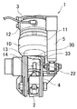
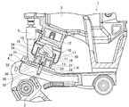
- FIG. 1 is a front view of a cab suspension structure according to an embodiment of the present disclosure.
- FIG. 2 is an enlarged perspective view of a joint portion between the air spring and the link arm of FIG.
- FIG. 3 is a cross-sectional view of the cab suspension structure of FIG.
- FIG. 4 is a cross-sectional view showing a state in which the seating portion of FIG. 3 has moved away from the spring support portion and moved upward.
- FIG. 5 is a perspective view showing the shaft portion, the shaft movement restricting portion, and the shaft insertion hole of FIG. 3 in a partial cross section.
- FIG. 6A is a cross-sectional view showing a modified example of the shaft portion and the shaft movement restricting portion.
- FIG. 6B is a perspective view showing another modification of the shaft movement restricting portion.
- the front-rear direction in the following description means the front-rear direction of the vehicle.
- a cab suspension structure 1 includes a frame side bracket 2 attached to a chassis frame (lower structure) (not shown) of a tiltable vehicle (truck), and a cab (not shown).
- the cab side bracket 3 attached to the structure), the link arm 4 rotatably connected to both the frame side bracket 2 and the cab side bracket 3, and the cab side bracket 3 and the link arm 4 are provided.
- an air spring 10 and a shock absorber 5 are provided with a plate-shaped spring support portion 30 on which the air spring 10 is placed.
- the cab is supported by the chassis frame so as to be able to tilt (tilt) obliquely upward and frontward about a tilt shaft (not shown).
- the shock absorber 5 attenuates the vibration transmitted between the link arm 4 and the cab side bracket 3 by resisting relative movement between the cab side bracket 3 and the link arm 4.
- the air spring 10 includes a bellows 11 that forms an air chamber and is capable of contracting, a fixing portion 12 that is provided on the upper end side of the bellows 11 and is fixed to the cab side bracket 3, A seat portion 13 provided on the lower end side of the bellows 11 and placed on the spring support portion 30 of the link arm 4, a shaft portion 14 provided on the seat portion 13 and extending in the contracting direction of the bellows 11, and a seat portion 13 of the seat portion 13. And a stopper 15 provided on the upper surface.
- the air spring 10 functions as an air spring that relieves an impact transmitted from the link arm 4 to the cab side bracket 3 by filling the bellows 11 with air.
- the stopper 15 contacts the fixed portion 12 when the air pressure inside the bellows 11 is reduced, and prevents the seating portion 13 and the fixed portion 12 from approaching (interfering with each other).
- the air spring 10 is fixed to the cab, and in the seated state in which the lower seating portion 13 of the air spring 10 is placed on the spring supporting portion 30 on the chassis frame side, the air spring 10 is placed between the cab and the chassis frame.
- the cab is elastically supported by being interposed.
- the air spring 10 moves upward together with the cab from the seated state, and the seating portion 13 is separated upward from the spring supporting portion 30.
- the seating portion 13 has an H-shaped cross section integrally including a cylindrical peripheral wall 16 and a disc-shaped intermediate wall 17, and the entire peripheral edge of the intermediate wall 17 is continuous from the inner peripheral surface of the intermediate portion of the peripheral wall 16.
- a concave space 18 that opens downward is defined by the inner peripheral surface of the peripheral wall 16 and the lower surface of the intermediate wall 17 in the lower portion of the seat portion 13.
- An annular lower end surface of the peripheral wall 16 constitutes a first abutting portion 19 that is placed in contact with the spring support portion 30 in a seated state, and a lower surface of the intermediate wall 17 intersects with a vertical direction in a seated state.
- the first facing surface 20 is formed.
- the shaft portion 14 projects linearly from the first facing surface 20 into the recessed space 18 below.
- the shaft portion 14 has a cylindrical boss portion 21 that integrally projects downward from the central portion of the first facing surface 20, and a guide pin 22 that is detachably fixed to the lower surface of the boss portion 21 and extends downward. ..
- the guide pin 22 has a columnar shape that is thinner (smaller outer diameter) than the boss portion 21 and is mounted coaxially with the boss portion 21.
- the guide pin 22 is attached to the boss portion 21 by screwing the male screw portion 23 formed on the upper end portion of the guide pin 22 into the female screw hole 24 formed in the boss portion 21 and tightening.
- the lower end portion of the guide pin 22 has a shape (for example, the shape of a bolt head of a hexagonal bolt) that can be engaged with a tightening tool.
- the upper surface of the spring support portion 30 intersects with the second contact portion 31 that contacts the first contact portion 19 of the air spring 10 in the seated state, and the first contact surface 20 of the air spring 10 that intersects with the second contact portion in the vertical direction in the seated state. It constitutes a second facing surface 32 that is spaced downward and faces the second facing surface 32, and the second facing surface 32 is provided with a shaft insertion hole 33.
- the shaft insertion hole 33 vertically penetrates the spring support portion 30.
- a cylindrical shaft movement restricting portion 34 is fixed to the second facing surface 32.
- the shaft movement restricting portion 34 is disposed coaxially with the shaft insertion hole 33, extends upward from the second facing surface 32, and is housed in the recessed space 18 of the seating portion 13 in a seated state.
- the inner peripheral surface of the shaft movement restricting portion 34 defines a shaft insertion space 35 (see FIGS. 4 and 5) that communicates with the shaft insertion hole 33.
- the shaft portion 14 In the seated state, the shaft portion 14 is inserted through the shaft insertion hole 33 and the shaft insertion space 35, and the lower end of the shaft portion 14 projects below the spring support portion 30.
- the shaft movement restricting portion 34 may be provided integrally with the spring supporting portion 30.
- the inner diameter of the shaft movement restricting portion 34 is slightly larger than the outer diameter of the boss portion 21, and the inner diameter of the shaft insertion hole 33 is slightly larger than the outer diameter of the guide pin 22 and smaller than the outer diameter of the boss portion 21. .. That is, the shaft insertion space 35 has a size that allows the boss portion 21 to enter, and the shaft insertion hole 33 has a size that allows the guide pin 22 to enter and the boss portion 21 cannot enter.
- a taper-shaped guide surface 36 is formed at the upper end edge (end edge on the shaft insertion space 35 side) of the inner peripheral surface of the shaft insertion hole 33, the diameter of which is increased toward the shaft insertion space 35.
- the protruding height of the boss portion 21 from the first facing surface 20 is such that the boss portion 21 does not interfere with the second facing surface 32 in the seated state where the first contact portion 19 and the second contact portion 31 are in contact.
- the height of protrusion of the peripheral wall 16 from the first facing surface 20 (the height from the first facing surface 20 to the first contact portion 19) or less.
- the protruding height of the shaft portion 14 from the first facing surface 20 (the height from the first facing surface 20 to the lower end of the guide pin 22) is such that the shaft portion 14 (guide The lower end of the pin 22) is set to a height that does not interfere with surrounding parts (for example, the frame side bracket 2).
- the projecting height of the axial movement restricting portion 34 from the second facing surface 32 is set such that the upper end of the axial movement restricting portion 34 does not interfere with the first facing surface 20 in the seated state, and the peripheral wall from the first facing surface 20 is large.
- the protrusion height is set to 16 or less.
- the shaft insertion hole 33 and the shaft movement restricting portion 34 allow the shaft portion 14 to reciprocate in a predetermined direction as the cab moves up and down, and the shaft portion 14 in a direction intersecting with the predetermined direction. Regulate movement. Further, for example, when the cab is lifted, the air spring 10 moves upward from the seated state together with the cab, the seating portion 13 is separated upward from the spring support portion 30, and the lower end of the shaft portion 14 (guide pin When the lower end 22 of the shaft 22 comes out of the shaft insertion hole 33, the lower end of the shaft portion 14 moves upward in the shaft insertion space 35.
- the shaft portion 14 in the seated state, the shaft portion 14 is inserted through the shaft insertion space 35 and the shaft insertion hole 33, so that the movement of the shaft portion 14 in the predetermined direction due to the raising and lowering of the cab is allowed and the predetermined direction.
- the state in which the movement of the shaft portion 14 in the direction intersecting with is maintained.
- the shaft portion 14 rises to move the shaft.
- the lower end of the portion 14 comes close to the shaft insertion space 35 and the cab further rises, the lower end of the shaft portion 14 comes out of the shaft insertion hole 33 and moves in the shaft insertion space 35.
- the movement of the shaft portion 14 in the direction intersecting with the predetermined direction is regulated by the shaft movement regulating portion 34, so that the air spring locked state is not released. It will be maintained continuously.
- the cylindrical shaft movement restricting portion 34 partitions the shaft insertion space 35 inward, when the lower end of the shaft portion 14 moves out of the shaft insertion hole 33 and moves in the shaft insertion space 35, it moves in a direction intersecting a predetermined direction.
- the movement of the shaft portion 14 can be reliably regulated by the shaft movement regulating portion 34.
- the shaft portion 14 is composed of the boss portion 21 and the guide pin 22, and the guide pin 22 is detachably fixed to the boss portion 21, only the guide pin 22 needs to be replaced when the guide pin 22 is damaged.
- the tapered guide surface 36 is provided at the upper end edge of the inner peripheral surface of the shaft insertion hole 33, the lower end of the guide pin 22 that has come out of the shaft insertion hole 33 is surely inserted into the shaft insertion hole 33 by the guide surface 36. Can be made.
- the seat portion 13 is provided with the first contact portion 19, the first facing surface 20, and the shaft portion 14, and the spring support portion 30 is provided with the second contact portion 31, the second facing surface 32, and the shaft portion 14.
- the insertion hole 33 and the shaft movement restricting portion 34 are provided, conversely, the second contact portion, the second facing surface, the shaft insertion hole, and the shaft movement restricting portion (shaft insertion space) are provided in the seating portion.
- the spring support portion may be provided with the first contact portion, the first facing surface, and the shaft portion.
- the forms of the shaft portion 14, the shaft insertion hole 33, the shaft movement restricting portion 34, and the shaft insertion space 35 are not limited to the present embodiment, and can be set arbitrarily.
- a guide pin 25 having substantially the same thickness as the boss portion 21 (having substantially the same outer diameter) is attached to the boss portion 21, and the inner diameter of the shaft insertion hole 33 and the inner diameter of the shaft insertion space 35 are adjusted to each other. You may set up substantially equally. In this case, the lower end of the guide pin 25 that descends from the shaft insertion space 35 can be reliably inserted into the shaft insertion hole 33 without providing a tapered surface. Further, as shown in FIG.
- the shaft movement restricting portion 37 may be configured by a plurality of (for example, three) rods or tubes that linearly extend from the upper edge of the shaft insertion hole 33 (guide surface 36). .. In this case, the region surrounded by the three shaft movement restricting portions 37 becomes the shaft insertion space 38.
- the present disclosure can be applied to a vehicle including an air spring interposed between an upper structure and a lower structure.
Landscapes
- Engineering & Computer Science (AREA)
- Mechanical Engineering (AREA)
- General Engineering & Computer Science (AREA)
- Chemical & Material Sciences (AREA)
- Combustion & Propulsion (AREA)
- Transportation (AREA)
- Fluid-Damping Devices (AREA)
- Body Structure For Vehicles (AREA)
Abstract
エアスプリング10の着座部13は、第1当接部19と第1対向面20と軸部14とを有する。スプリング支持部30は、着座状態で第1当接部19と当接する第2当接部31と、第1対向面20から離間して対向する第2対向面32と、軸挿通孔33と、軸挿通孔33と連通する軸挿通空間35を区画するように第2対向面32から突出する軸移動規制部34とを有する。軸部14は、着座状態で軸挿通孔33及び軸挿通空間35を挿通する。着座状態からの上構造体の上昇により軸挿通孔33から抜けた軸部14の先端は、軸挿通空間35を移動する。軸挿通孔33から抜けた軸部14の先端は、着座状態への上構造体の下降により軸挿通空間35から軸挿通孔33へ進入する。
Description
本開示は、上構造体と下構造体との間にエアスプリングが介在する車両のエアスプリング係止構造に関する。
特許文献1には、車両のシャシフレームにフレーム側ブラケットを取付け、キャブにキャブ側ブラケットを取付け、フレーム側ブラケットとキャブ側ブラケットとをリンクアームによって連結し、キャブ側ブラケットとリンクアームとの間にエアスプリングを設けたキャブサスペンション構造が記載されている。
エアスプリングは、空気室を形成して収縮可能なベローズと、ベローズの上端側に設けられてキャブ側ブラケットに固定された固定部と、ベローズの下端側に設けられてリンクアームに係合する着座部と、着座部に設けられてベローズの収縮方向に延びる軸部と、着座部の上面に設けられたストッパとを備える。着座部には、雌ねじ部が形成され、軸部は、雌ねじ部に螺合する。エアスプリングは、ベローズ内に空気を充填しておくことで、リンクアームからキャブ側ブラケットに伝達される衝撃を緩和する空気ばねとして機能する。リンクアームの上面には、エアスプリングの軸部が挿通される貫通孔が形成されている。軸部は、着座部の雌ねじ部に螺合される雄ねじ部と、雄ねじ部よりも外径が大きい軸部本体とを備える。雄ねじ部と軸部本体との境界部分には、段差面が形成され、軸部を締め付けることで段差面が着座部の下端面に押し付けられる。着座部の下端面がリンクアームの上面に押し付けられた状態では、軸部の下端とフレーム側ブラケットとの隙間寸法は、t1となっている。軸部本体の長さ寸法はLであり、軸部本体の着座部から突出した部分の長さはLとなる。ベローズ内の空気圧が低下すると、ベローズが収縮して、ストッパが固定部に当接するまで着座部が上昇する場合がある。この状態は、着座部がリンクアームから最も離間した状態である。このとき、着座部とリンクアームとの距離をt2とすると、軸部本体の長さ寸法Lは、このt2よりも大きく設定されている。したがって、この場合であっても、軸部の下端部は、依然としてリンクアームの貫通孔に挿通された状態であり、軸部がリンクアームから外れるのが防止されている。
特許文献1の構造では、着座部からの軸部の突出高さ(軸本体の長さ)を増大させると、着座部の下端面がリンクアームの上面に押し付けられた状態(着座状態)での軸部の下端とフレーム側ブラケットとの隙間が減少するため、軸部の最大突出高さは、フレーム側ブラケットと干渉する長さ未満に自ずと制限される。このため、車両のレイアウトによっては軸部の突出高さを十分に確保することができず、着座部がリンクアームから最も離間するまで軸部が貫通孔を挿通した状態(エアスプリング係止状態)を継続して維持させることが難しい場合がある。
そこで本開示は、軸部の突出高さの増大を抑えつつ、エアスプリング係止状態の解除を確実に防止することが可能なエアスプリング係止構造の提供を目的とする。
上記目的を達成すべく、本開示の第1の態様は、上構造体に対してエアスプリングが固定され、エアスプリングの下部の着座部が下構造体側のスプリング支持部に載置された着座状態でエアスプリングが上構造体と下構造体との間に介在して上構造体を弾性支持し、エアスプリングが上構造体とともに着座状態から上方へ移動することにより着座部がスプリング支持部から上方へ離間するエアスプリング係止構造であって、着座部及びスプリング支持部の一方は、第1当接部と、着座状態で上下方向と交叉する第1対向面と、第1対向面から突出して上下方向に延びる軸部とを有する。着座部及びスプリング支持部の他方は、着座状態で第1当接部と当接する第2当接部と、着座状態で上下方向と交叉し第1対向面から離間して対向する第2対向面と、第2対向面に設けられた軸挿通孔と、軸挿通孔と連通する軸挿通空間を区画するように第2対向面から突出する軸移動規制部とを有する。なお、軸部が延びる上下方向は、鉛直方向に限定されず、鉛直方向に対して傾斜する方向も含む。
軸部は、着座状態で軸挿通空間及び軸挿通孔を挿通する。軸挿通孔及び軸移動規制部は、上構造体の昇降に伴う軸部の所定方向への移動を許容するとともに、所定方向と交叉する方向への軸部の移動を規制する。着座状態からの上構造体の上昇により軸挿通孔から抜けた軸部の先端は、軸挿通空間を移動する。軸挿通孔から抜けた軸部の先端は、着座状態への上構造体の下降により軸挿通空間から軸挿通孔へ進入する。
上記構成では、エアスプリングの下部の着座部が下構造体側のスプリング支持部に載置された着座状態で軸部が軸挿通空間及び軸挿通孔を挿通する。これにより、上構造体の昇降に伴う軸部の所定方向への移動が許容され、且つ所定方向と交叉する方向への軸部の移動が規制された状態(エアスプリング係止状態)が維持される。
着座状態から上構造体が上昇し、着座部がスプリング支持部から離れて上方へ移動する(第1当接部と第2当接部とが離間する)と、軸部と軸挿通孔との相対移動により軸部の先端と軸挿通空間とが近付き、上構造体がさらに上昇すると、軸部の先端が軸挿通孔から抜けて軸挿通空間を移動する。軸部の先端が軸挿通孔から抜けた後は、軸移動規制部が所定方向と交叉する方向への軸部の移動を規制するため、エアスプリング係止状態が解除されずに継続して維持される。このように、軸挿通孔が軸挿通空間によって第1対向面側に実質的に延長されるので、軸移動規制部(軸挿通空間)を設けない場合に比べて、第1対向面からの軸部の突出高さを短縮することができる。従って、軸部の突出高さの増大を抑えつつ、エアスプリング係止状態の解除を確実に防止することができる。
本開示の第2の態様は、第1の態様のエアスプリング係止構造であって、軸移動規制部は、軸挿通空間を内側に区画する筒形状である。
上記構成では、筒形状の軸移動規制部が軸挿通空間を内側に区画するので、軸部の先端が軸挿通孔から抜けて軸挿通空間を移動する場合において、所定方向と交叉する方向への軸部の移動を軸移動規制部によって確実に規制することができる。
本開示の第3の態様は、第1又は第2の態様のエアスプリング係止構造であって、軸部は、第1対向面から一体的に突出するボス部と、ボス部よりも細くボス部に着脱可能に固定されて上下方向に延びるガイドピンとを有する。軸挿通空間は、ボス部が進入可能な大きさであり、軸挿通孔は、ガイドピンが進入可能で、且つボス部が進入不可能な大きさである。軸挿通孔の内周面の軸挿通空間側の端縁には、着座状態への上構造体の下降に伴って軸挿通空間を移動するガイドピンの先端を軸挿通孔へ案内するテーパ状のガイド面が形成されている。
上記構成では、軸挿通孔から抜けたガイドピンの先端を、ガイド面によって軸挿通孔へ確実に進入させることができる。また、ガイドピンをボス部に着脱可能に固定するので、ガイドピンが損傷した際にはガイドピンのみを交換すればよい。
本開示によれば、軸部の突出高さの増大を抑えつつ、エアスプリング係止状態の解除を確実に防止することができる。
以下、本開示の一実施形態に係るキャブサスペンション構造1について図面を参照して説明する。なお、以下の説明における前後方向は、車両の前後方向を意味する。
図1及び図2に示すように、キャブサスペンション構造1は、チルト可能な車両(トラック)の図示略のシャシフレーム(下構造体)に取付けられたフレーム側ブラケット2と、図示略のキャブ(上構造体)に取り付けられたキャブ側ブラケット3と、フレーム側ブラケット2とキャブ側ブラケット3の双方に回転可能に連結されたリンクアーム4と、キャブ側ブラケット3とリンクアーム4との間に設けられたエアスプリング10及びショックアブソーバ5とを備える。リンクアーム4には、エアスプリング10が載置される板状のスプリング支持部30が設けられている。キャブは、図示略のチルト軸を中心として前斜め上方へ傾動(チルト)可能にシャシフレームに支持されている。
ショックアブソーバ5は、キャブ側ブラケット3とリンクアーム4との相対移動に抵抗することで、リンクアーム4とキャブ側ブラケット3との間で伝達される振動を減衰させる。
図3及び図4に示すように、エアスプリング10は、空気室を形成して収縮可能なベローズ11と、ベローズ11の上端側に設けられてキャブ側ブラケット3に固定される固定部12と、ベローズ11の下端側に設けられてリンクアーム4のスプリング支持部30に載置される着座部13と、着座部13に設けられてベローズ11の収縮方向に延びる軸部14と、着座部13の上面に設けられたストッパ15とを備える。エアスプリング10は、ベローズ11内に空気が充填されることによって、リンクアーム4からキャブ側ブラケット3に伝達される衝撃を緩和する空気ばねとして機能する。ストッパ15は、ベローズ11内の空気圧が低下した場合に固定部12に当接して、着座部13と固定部12との接近(干渉)を阻止する。
このように、エアスプリング10は、キャブに対して固定され、エアスプリング10の下部の着座部13がシャシフレーム側のスプリング支持部30に載置された着座状態で、キャブとシャシフレームとの間に介在してキャブを弾性支持する。また、キャブのチルト時には、エアスプリング10は着座状態からキャブと共に上方へ移動し、着座部13はスプリング支持部30から上方へ離間する。
着座部13は、円筒状の周壁16と円板状の中間壁17とを一体的に有するH状断面であり、中間壁17の全周縁が周壁16の中間部の内周面から連続する。着座部13の下部には、下方へ開口する凹状空間18が周壁16の内周面と中間壁17の下面とによって区画形成されている。周壁16の円環状の下端面は、着座状態でスプリング支持部30に当接して載置される第1当接部19を構成し、中間壁17の下面は、着座状態で上下方向と交叉する第1対向面20を構成する。軸部14は、第1対向面20から下方の凹状空間18へ突出して直線状に延びる。
軸部14は、第1対向面20の中心部から下方へ一体的に突出する円柱状のボス部21と、ボス部21の下面に着脱可能に固定されて下方へ延びるガイドピン22とを有する。ガイドピン22は、ボス部21よりも細い(外径が小さい)円柱状であり、ボス部21と同軸状に取付けられる。
本実施形態では、ガイドピン22の上端部に形成された雄ネジ部23を、ボス部21に形成された雌ネジ孔24に螺合して締付けることによって、ガイドピン22がボス部21に取付けられる。ガイドピン22の下端部は、締付用の工具と係合可能な形状(例えば、六角ボルトのボルト頭部の形状)を有する。
スプリング支持部30の上面は、着座状態でエアスプリング10の第1当接部19と当接する第2当接部31と、着座状態で上下方向と交叉しエアスプリング10の第1対向面20から下方に離間して対向する第2対向面32とを構成し、第2対向面32には、軸挿通孔33が設けられている。軸挿通孔33は、スプリング支持部30を上下方向に貫通する。
図3~図5に示すように、第2対向面32には円筒状の軸移動規制部34が固定される。軸移動規制部34は、軸挿通孔33と同軸状に配置され、第2対向面32から上方へ突出して延び、着座状態で着座部13の凹状空間18に収容される。軸移動規制部34の内周面は、軸挿通孔33と連通する軸挿通空間35(図4及び図5参照)を区画する。着座状態において、軸部14は軸挿通孔33及び軸挿通空間35を挿通し、軸部14の下端はスプリング支持部30の下方へ突出する。なお、軸移動規制部34をスプリング支持部30と一体的に設けてもよい。
軸移動規制部34の内径は、ボス部21の外径よりも僅かに大きく、軸挿通孔33の内径は、ガイドピン22の外径よりも僅かに大きく且つボス部21の外径よりも小さい。すなわち、軸挿通空間35は、ボス部21が進入可能な大きさであり、軸挿通孔33は、ガイドピン22が進入可能で、且つボス部21が進入不可能な大きさである。軸挿通孔33の内周面の上端縁(軸挿通空間35側の端縁)には、軸挿通空間35に向かって拡径するテーパ状のガイド面36が形成されている。
第1対向面20からのボス部21の突出高さは、第1当接部19と第2当接部31とが当接する着座状態でボス部21が第2対向面32と干渉しないように、第1対向面20からの周壁16の突出高さ(第1対向面20から第1当接部19までの高さ)以下に設定される。第1対向面20からの軸部14の突出高さ(第1対向面20からガイドピン22の下端までの高さ)は、着座状態でスプリング支持部30の下方へ突出する軸部14(ガイドピン22)の下端が周囲の部品(例えばフレーム側ブラケット2)と干渉しない高さに設定される。また、第2対向面32からの軸移動規制部34の突出高さは、着座状態で軸移動規制部34の上端が第1対向面20と干渉しないように、第1対向面20からの周壁16の突出高さ以下に設定される。
軸挿通孔33及び軸移動規制部34(軸挿通空間35)は、キャブの昇降に伴う軸部14の所定方向への往復移動を許容するとともに、所定方向と交叉する方向への軸部14の移動を規制する。また、例えばキャブチルト時のようにキャブが上昇し、エアスプリング10が着座状態からキャブと共に上方へ移動し、着座部13がスプリング支持部30から上方へ離間して、軸部14の下端(ガイドピン22の下端)が軸挿通孔33から抜けると、軸部14の下端は軸挿通空間35を上方へ移動する。反対に、チルト状態からキャブが下降すると、軸挿通孔33から抜けた軸部14の下端は、着座状態へのエアスプリング10の下降により軸挿通空間35から軸挿通孔33へ進入する。ガイド面36は、着座状態への下降に伴って軸挿通空間35を下降するガイドピン22の下端を軸挿通孔33へ案内する。
本実施形態によれば、着座状態では、軸部14が軸挿通空間35及び軸挿通孔33を挿通するので、キャブの昇降に伴う軸部14の所定方向への移動が許容され、且つ所定方向と交叉する方向への軸部14の移動が規制された状態(エアスプリング係止状態)が維持される。
着座状態からキャブが上昇し、着座部13がスプリング支持部30から離れて上方へ移動する(第1当接部19が第2当接部31から離間する)と、軸部14の上昇により軸部14の下端と軸挿通空間35とが近付き、キャブがさらに上昇すると、軸部14の下端が軸挿通孔33から抜けて軸挿通空間35を移動する。軸部14の下端が軸挿通孔33から抜けた後は、所定方向と交叉する方向への軸部14の移動を軸移動規制部34が規制するため、エアスプリング係止状態が解除されずに継続して維持される。このように、軸挿通孔33が軸挿通空間35によって上方(第1対向面20側)に実質的に延長されるので、軸移動規制部34(軸挿通空間35)を設けない場合に比べて、第1対向面20からの軸部14の突出高さを短縮することができる。従って、軸部14の突出高さの増大を抑えつつ、エアスプリング係止状態の解除を確実に防止することができる。
円筒状の軸移動規制部34が軸挿通空間35を内側に区画するので、軸部14の下端が軸挿通孔33から抜けて軸挿通空間35を移動する場合において、所定方向と交叉する方向への軸部14の移動を軸移動規制部34によって確実に規制することができる。
軸部14をボス部21とガイドピン22とによって構成し、ガイドピン22をボス部21に着脱可能に固定するので、ガイドピン22が損傷した際にはガイドピン22のみを交換すればよい。
また、軸挿通孔33の内周面の上端縁にテーパ状のガイド面36を設けたので、軸挿通孔33から抜けたガイドピン22の下端をガイド面36によって軸挿通孔33へ確実に進入させることができる。
以上、本開示について、上記実施形態に基づいて説明を行ったが、本開示は上記実施形態の内容に限定されるものではなく、当然に本開示を逸脱しない範囲で適宜変更が可能である。すなわち、この実施形態に基づいて当業者等によりなされる他の実施形態、実施例および運用技術等は全て本開示の範疇に含まれることは勿論である。
例えば、上記実施形態では、着座部13に第1当接部19と第1対向面20と軸部14とを設け、スプリング支持部30に第2当接部31と第2対向面32と軸挿通孔33と軸移動規制部34(軸挿通空間35)とを設けたが、反対に、着座部に第2当接部と第2対向面と軸挿通孔と軸移動規制部(軸挿通空間)とを設け、スプリング支持部に第1当接部と第1対向面と軸部とを設けてもよい。
また、軸部14、軸挿通孔33、軸移動規制部34及び軸挿通空間35の形態は本実施形態に限定されず、任意に設定可能である。例えば、図6Aに示すように、ボス部21と略同じ太さの(外径が略等しい)ガイドピン25をボス部21に取付け、軸挿通孔33の内径と軸挿通空間35の内径とを略等しく設定してもよい。この場合、テーパ面を設けることなく、軸挿通空間35内から下降するガイドピン25の下端を軸挿通孔33へ確実に進入させることができる。また、図6Bに示すように、軸挿通孔33(ガイド面36)の上端周縁から直線状に延びる複数(例えば3本)の棒体又は管体によって軸移動規制部37を構成してもよい。この場合、3本の軸移動規制部37によって囲まれる領域が軸挿通空間38となる。
本出願は、2018年12月27日付で出願された日本国特許出願(特願2018-243893)に基づくものであり、その内容はここに参照として取り込まれる。
本開示は、上構造体と下構造体との間に介在するエアスプリングを備えた車両に適用することができる。
1:キャブサスペンション構造
2:フレーム側ブラケット
3:キャブ側ブラケット
4:リンクアーム
5:ショックアブソーバ
10:エアスプリング
11:ベローズ
12:固定部
13:着座部
14:軸部
15:ストッパ
16:周壁
17:中間壁
18:凹状空間
19:第1当接部
20:第1対向面
21:ボス部
22,25:ガイドピン
23:雄ネジ部
24:雌ネジ孔
30:スプリング支持部
31:第2当接部
32:第2対向面
33:軸挿通孔
34,37:軸移動規制部
35,38:軸挿通空間
36:ガイド面
2:フレーム側ブラケット
3:キャブ側ブラケット
4:リンクアーム
5:ショックアブソーバ
10:エアスプリング
11:ベローズ
12:固定部
13:着座部
14:軸部
15:ストッパ
16:周壁
17:中間壁
18:凹状空間
19:第1当接部
20:第1対向面
21:ボス部
22,25:ガイドピン
23:雄ネジ部
24:雌ネジ孔
30:スプリング支持部
31:第2当接部
32:第2対向面
33:軸挿通孔
34,37:軸移動規制部
35,38:軸挿通空間
36:ガイド面
Claims (3)
- 上構造体に対してエアスプリングが固定され、前記エアスプリングの下部の着座部が下構造体側のスプリング支持部に載置された着座状態で前記エアスプリングが前記上構造体と前記下構造体との間に介在して前記上構造体を弾性支持し、前記エアスプリングが前記上構造体とともに前記着座状態から上方へ移動することにより前記着座部が前記スプリング支持部から上方へ離間するエアスプリング係止構造であって、
前記着座部及び前記スプリング支持部の一方は、第1当接部と、前記着座状態で上下方向と交叉する第1対向面と、前記第1対向面から突出して上下方向に延びる軸部とを有し、
前記着座部及び前記スプリング支持部の他方は、前記着座状態で前記第1当接部と当接する第2当接部と、前記着座状態で上下方向と交叉し前記第1対向面から離間して対向する第2対向面と、前記第2対向面に設けられた軸挿通孔と、前記軸挿通孔と連通する軸挿通空間を区画するように前記第2対向面から突出する軸移動規制部とを有し、
前記軸部は、前記着座状態で前記軸挿通空間及び前記軸挿通孔を挿通し、
前記軸挿通孔及び前記軸移動規制部は、前記上構造体の昇降に伴う前記軸部の所定方向への移動を許容するとともに、前記所定方向と交叉する方向への前記軸部の移動を規制し、
前記着座状態からの前記上構造体の上昇により前記軸挿通孔から抜けた前記軸部の先端は、前記軸挿通空間を移動し、
前記軸挿通孔から抜けた前記軸部の先端は、前記着座状態への前記上構造体の下降により前記軸挿通空間から前記軸挿通孔へ進入する
ことを特徴とするエアスプリング係止構造。 - 請求項1に記載のエアスプリング係止構造であって、
前記軸移動規制部は、前記軸挿通空間を内側に区画する筒形状である
ことを特徴とするエアスプリング係止構造。 - 請求項1又は請求項2に記載のエアスプリング係止構造であって、
前記軸部は、前記第1対向面から一体的に突出するボス部と、前記ボス部よりも細く前記ボス部に着脱可能に固定されて上下方向に延びるガイドピンとを有し、
前記軸挿通空間は、前記ボス部が進入可能な大きさであり、
前記軸挿通孔は、前記ガイドピンが進入可能で、且つ前記ボス部が進入不可能な大きさであり、
前記軸挿通孔の内周面の前記軸挿通空間側の端縁には、前記着座状態への前記上構造体の下降に伴って前記軸挿通空間を移動する前記ガイドピンの先端を前記軸挿通孔へ案内するテーパ状のガイド面が形成されている
ことを特徴とするエアスプリング係止構造。
Priority Applications (1)
| Application Number | Priority Date | Filing Date | Title |
|---|---|---|---|
| CN201980086696.5A CN113286954B (zh) | 2018-12-27 | 2019-12-25 | 空气弹簧卡止结构 |
Applications Claiming Priority (2)
| Application Number | Priority Date | Filing Date | Title |
|---|---|---|---|
| JP2018-243893 | 2018-12-27 | ||
| JP2018243893A JP7153232B2 (ja) | 2018-12-27 | 2018-12-27 | エアスプリング係止構造 |
Publications (1)
| Publication Number | Publication Date |
|---|---|
| WO2020138141A1 true WO2020138141A1 (ja) | 2020-07-02 |
Family
ID=71129423
Family Applications (1)
| Application Number | Title | Priority Date | Filing Date |
|---|---|---|---|
| PCT/JP2019/050759 Ceased WO2020138141A1 (ja) | 2018-12-27 | 2019-12-25 | エアスプリング係止構造 |
Country Status (3)
| Country | Link |
|---|---|
| JP (1) | JP7153232B2 (ja) |
| CN (1) | CN113286954B (ja) |
| WO (1) | WO2020138141A1 (ja) |
Citations (5)
| Publication number | Priority date | Publication date | Assignee | Title |
|---|---|---|---|---|
| JPS6020977U (ja) * | 1983-07-22 | 1985-02-13 | 日産ディーゼル工業株式会社 | チルトキヤプのロツククツシヨン装置 |
| JPH0618169U (ja) * | 1992-08-21 | 1994-03-08 | 日野自動車工業株式会社 | キャブのサスペンション装置 |
| US5921532A (en) * | 1994-10-07 | 1999-07-13 | Neway Anchorlok International, Inc. | Air spring with internal support member |
| JP2004090865A (ja) * | 2002-09-03 | 2004-03-25 | Hino Motors Ltd | キャブ用エアスプリングの取付構造 |
| JP2017030411A (ja) * | 2015-07-29 | 2017-02-09 | いすゞ自動車株式会社 | エアスプリングの接合構造 |
Family Cites Families (4)
| Publication number | Priority date | Publication date | Assignee | Title |
|---|---|---|---|---|
| JP4236041B2 (ja) * | 2004-02-02 | 2009-03-11 | 日産ディーゼル工業株式会社 | エアスプリング取付構造及び取付方法 |
| CN202080356U (zh) * | 2011-05-10 | 2011-12-21 | 北汽福田汽车股份有限公司 | 驾驶室后悬置系统和重型车辆 |
| JP6308819B2 (ja) * | 2014-03-10 | 2018-04-11 | 東洋ゴム工業株式会社 | 軸ばね |
| JP6424086B2 (ja) * | 2014-12-26 | 2018-11-14 | 東洋ゴム工業株式会社 | 空気ばね |
-
2018
- 2018-12-27 JP JP2018243893A patent/JP7153232B2/ja active Active
-
2019
- 2019-12-25 CN CN201980086696.5A patent/CN113286954B/zh active Active
- 2019-12-25 WO PCT/JP2019/050759 patent/WO2020138141A1/ja not_active Ceased
Patent Citations (5)
| Publication number | Priority date | Publication date | Assignee | Title |
|---|---|---|---|---|
| JPS6020977U (ja) * | 1983-07-22 | 1985-02-13 | 日産ディーゼル工業株式会社 | チルトキヤプのロツククツシヨン装置 |
| JPH0618169U (ja) * | 1992-08-21 | 1994-03-08 | 日野自動車工業株式会社 | キャブのサスペンション装置 |
| US5921532A (en) * | 1994-10-07 | 1999-07-13 | Neway Anchorlok International, Inc. | Air spring with internal support member |
| JP2004090865A (ja) * | 2002-09-03 | 2004-03-25 | Hino Motors Ltd | キャブ用エアスプリングの取付構造 |
| JP2017030411A (ja) * | 2015-07-29 | 2017-02-09 | いすゞ自動車株式会社 | エアスプリングの接合構造 |
Also Published As
| Publication number | Publication date |
|---|---|
| CN113286954B (zh) | 2023-03-21 |
| CN113286954A (zh) | 2021-08-20 |
| JP7153232B2 (ja) | 2022-10-14 |
| JP2020104630A (ja) | 2020-07-09 |
Similar Documents
| Publication | Publication Date | Title |
|---|---|---|
| US9829062B2 (en) | Bump stopper cap | |
| CN105378323B (zh) | 筒式隔振装置 | |
| CN105452706B (zh) | 筒式隔振装置 | |
| WO2012049844A1 (en) | Vehicular fastening structure | |
| CN106794735A (zh) | 用于车辆悬架系统的弹簧座组件 | |
| JP5186138B2 (ja) | 鉄道車両用の防振ゴムストッパ | |
| US20230010080A1 (en) | Spring seat, method for producing a spring seat, vibration damper and level adjustment device | |
| KR102683449B1 (ko) | 가이드부가 구비된 차량용 에어 서스펜션 | |
| JP2019168088A (ja) | ゴムストッパ | |
| JP7153232B2 (ja) | エアスプリング係止構造 | |
| EP3124823A1 (en) | Shock absorber | |
| JP6681189B2 (ja) | クッション体を有するアッパーサポート | |
| KR102320225B1 (ko) | 전장 및 감쇠력 조절식 역립식 에어서스펜션 | |
| JP5965274B2 (ja) | 車体側パネルへのストラットロッドの取付構造 | |
| US20200229601A1 (en) | Overturn preventing device | |
| JP6828664B2 (ja) | リーフスプリング支持構造及びその製造方法 | |
| JP5893844B2 (ja) | ストラットマウントならびに、ストラットロッドの、車体側パネルへの取付け構造 | |
| KR102664095B1 (ko) | 변속기 마운트 | |
| CN111114273B (zh) | 动力总成悬置 | |
| US11807145B2 (en) | Headrest level adjustment mechanism | |
| KR102909379B1 (ko) | 후륜 멤버 부쉬 | |
| KR100551258B1 (ko) | 트럭의 캡 마운팅 구조 | |
| KR102755944B1 (ko) | 차량용 현가장치 | |
| JP2017030411A (ja) | エアスプリングの接合構造 | |
| KR102063065B1 (ko) | 차량용 로어암 |
Legal Events
| Date | Code | Title | Description |
|---|---|---|---|
| 121 | Ep: the epo has been informed by wipo that ep was designated in this application |
Ref document number: 19901471 Country of ref document: EP Kind code of ref document: A1 |
|
| NENP | Non-entry into the national phase |
Ref country code: DE |
|
| 122 | Ep: pct application non-entry in european phase |
Ref document number: 19901471 Country of ref document: EP Kind code of ref document: A1 |