WO2020138131A1 - 複合シート、吸収性物品、及び複合シートの製造方法 - Google Patents
複合シート、吸収性物品、及び複合シートの製造方法 Download PDFInfo
- Publication number
- WO2020138131A1 WO2020138131A1 PCT/JP2019/050740 JP2019050740W WO2020138131A1 WO 2020138131 A1 WO2020138131 A1 WO 2020138131A1 JP 2019050740 W JP2019050740 W JP 2019050740W WO 2020138131 A1 WO2020138131 A1 WO 2020138131A1
- Authority
- WO
- WIPO (PCT)
- Prior art keywords
- sheet
- welded portion
- pitch
- composite sheet
- welded
- Prior art date
- Legal status (The legal status is an assumption and is not a legal conclusion. Google has not performed a legal analysis and makes no representation as to the accuracy of the status listed.)
- Ceased
Links
Images

Classifications
-
- A—HUMAN NECESSITIES
- A61—MEDICAL OR VETERINARY SCIENCE; HYGIENE
- A61F—FILTERS IMPLANTABLE INTO BLOOD VESSELS; PROSTHESES; DEVICES PROVIDING PATENCY TO, OR PREVENTING COLLAPSING OF, TUBULAR STRUCTURES OF THE BODY, e.g. STENTS; ORTHOPAEDIC, NURSING OR CONTRACEPTIVE DEVICES; FOMENTATION; TREATMENT OR PROTECTION OF EYES OR EARS; BANDAGES, DRESSINGS OR ABSORBENT PADS; FIRST-AID KITS
- A61F13/00—Bandages or dressings; Absorbent pads
- A61F13/15—Absorbent pads, e.g. sanitary towels, swabs or tampons for external or internal application to the body; Supporting or fastening means therefor; Tampon applicators
- A61F13/45—Absorbent pads, e.g. sanitary towels, swabs or tampons for external or internal application to the body; Supporting or fastening means therefor; Tampon applicators characterised by the shape
- A61F13/49—Absorbent pads, e.g. sanitary towels, swabs or tampons for external or internal application to the body; Supporting or fastening means therefor; Tampon applicators characterised by the shape specially adapted to be worn around the waist, e.g. diapers or nappies
-
- A—HUMAN NECESSITIES
- A61—MEDICAL OR VETERINARY SCIENCE; HYGIENE
- A61F—FILTERS IMPLANTABLE INTO BLOOD VESSELS; PROSTHESES; DEVICES PROVIDING PATENCY TO, OR PREVENTING COLLAPSING OF, TUBULAR STRUCTURES OF THE BODY, e.g. STENTS; ORTHOPAEDIC, NURSING OR CONTRACEPTIVE DEVICES; FOMENTATION; TREATMENT OR PROTECTION OF EYES OR EARS; BANDAGES, DRESSINGS OR ABSORBENT PADS; FIRST-AID KITS
- A61F13/00—Bandages or dressings; Absorbent pads
- A61F13/15—Absorbent pads, e.g. sanitary towels, swabs or tampons for external or internal application to the body; Supporting or fastening means therefor; Tampon applicators
- A61F13/51—Absorbent pads, e.g. sanitary towels, swabs or tampons for external or internal application to the body; Supporting or fastening means therefor; Tampon applicators characterised by the outer layers of the pads
Definitions
- the present invention relates to a composite sheet used for absorbent articles and the like, an absorbent article having the composite sheet, and a method for manufacturing the composite sheet.
- Patent Document 1 discloses a composite sheet that constitutes a waist belt of an absorbent article.
- the composite sheet of Patent Document 1 includes an inner layer sheet, an outer layer sheet laminated with the inner layer sheet, a thread-like stretchable member arranged between the inner layer sheet and the outer layer sheet, and a joint portion in which the inner layer sheet and the outer layer sheet are joined. And have.
- a plurality of elastic members extend in the width direction and are arranged at intervals in the front-rear direction.
- a plurality of joints are arranged at intervals in the width direction and the front-rear direction.
- the joint portion of the composite sheet of Patent Document 1 joins the inner layer sheet and the outer layer sheet by heat welding.
- the stretchable member contracts, the sheets between the adjacent joints are deformed so as to swell in the thickness direction, and folds made of the sheet are formed between the adjacent joints.
- the folds improve the feel of the composite sheet.
- a composite sheet according to one aspect is a composite sheet used for an absorbent article, the elastic member and a first sheet having a first welded portion that is disposed so as to overlap the elastic member and that has fibers welded thereto, A second sheet disposed between the first sheet and the stretchable member, the second sheet having a second welded portion to which fibers are welded, each of the first welded portion and the second welded portion being the stretchable member.
- a plurality of elastic members are arranged at intervals in the expansion/contraction direction, and the pitch of the first welding portion in the expansion/contraction direction is different from the pitch of the second welding portion in the expansion/contraction direction.
- the absorbent article according to one aspect is a front and rear direction, a width direction orthogonal to the front and rear direction, a front waistline region, a rear waistline region, and a crotch region disposed between the front waistline region and the rear waistline region.
- An absorptive body disposed across the crotch region, the front waistline region and the rear waistline region, a front waist belt that overlaps the absorbent body in the front waistline region in the thickness direction, and the rear waistline Absorbent article having a rear waist belt that overlaps the absorbent main body in the thickness direction in a region, and a composite sheet arranged on the skin side surface of the front waist belt and the skin side surface of the rear waist belt.
- the composite sheet at least the elastic member that expands and contracts in the width direction, and a first sheet that is disposed on the skin surface side of the elastic member and has a first welded portion in which fibers are welded, A second sheet disposed between the first sheet and the stretchable member, the second sheet having a second welded portion to which fibers are welded, each of the first welded portion and the second welded portion having the width A plurality of them are arranged at intervals in the direction, and a pitch of the first welded portion in the width direction is different from a pitch of the second welded portion in the width direction.
- a method of manufacturing a composite sheet includes a first sheet welding step of forming a first welded portion on a first sheet with an interval in the conveying direction, and a second sheet with a second sheet with an interval in the conveying direction. After the second sheet welding step of forming a welded portion, the first sheet welding step and the second sheet welding step, the second sheet is provided between the stretchable member extended in the transport direction and the first sheet.
- a stacking step of arranging the sheets, and the second sheet welding step forms the second welding portion at a pitch in the transport direction that is different from a pitch of the first welding portion in the transport direction.
- FIG. 3 is a cross-sectional view taken along the line AA of the absorbent article shown in FIG. 2. It is a schematic cross section of the 1st composite sheet as a composite sheet. It is a cross-sectional photograph of a 1st composite sheet. It is a schematic cross section of the 2nd composite sheet as a composite sheet. It is a cross-sectional photograph of a 2nd composite sheet.
- a composite sheet according to one aspect is a composite sheet used for an absorbent article, the elastic member and a first sheet having a first welded portion that is disposed so as to overlap the elastic member and that has fibers welded thereto, A second sheet disposed between the first sheet and the stretchable member, the second sheet having a second welded portion in which fibers are welded, each of the first welded portion and the second welded portion being the stretchable member.
- a plurality of elastic members are arranged at intervals in the expansion/contraction direction, and the pitch of the first welding portion in the expansion/contraction direction is different from the pitch of the second welding portion in the expansion/contraction direction.
- the first sheet is deformed by the contraction of the stretchable member so that the first welded portions swell in the thickness direction. Therefore, the folds are formed between the adjacent first welded portions on the first sheet.
- the second sheet is deformed by the contraction of the stretchable member so that the spaces between the second welded parts expand in the thickness direction. Therefore, the folds are formed between the adjacent second welded portions on the second sheet. Since the pitch of the first welded portion and the pitch of the second welded portion are different, the first welded portion and the second welded portion are displaced in the shrinking direction. Therefore, as compared with the form in which the first welded portion and the second welded portion are all overlapped with each other, the hardness of the composite sheet due to the welded portion can be reduced and the touch can be improved.
- the pitch of the first welded portion may be longer than the pitch of the second welded portion.
- the pitch of the second welded portions is short and the area between the second welded portions is large.
- the region between the second welded portions is a thinned sheet, which has low rigidity.
- the pitch of the first welded portions is long, and the area between the first welded portions in the first sheet is small.
- the first sheet has a small area of low rigidity, and has high rigidity as a whole.
- the second sheet having a low overall rigidity is arranged near the elastic member, and fine folds are easily formed on the second sheet.
- first sheet is farther from the stretchable member than the second sheet and the pitch of the first welded portion is relatively long, so that the first sheet is less likely to follow the fine folds of the second sheet, A relatively large fold is formed so as to bulge in the thickness direction from the second sheet. A space is formed between the first sheet and the second sheet, the cushioning property of the composite sheet is enhanced, and the touch can be improved.
- the pitch of the first welded portion may be shorter than the pitch of the second welded portion.
- the second sheet since the second sheet is sandwiched between the first sheet and the elastic member, it is easy to follow the small folds of the first sheet. Therefore, not only the large folds formed by the second welded portion but also the small folds formed by the first welded portion are easily formed on the second sheet. As a result, the folds of the composite sheet are likely to be uniform, the folds are prevented from locally touching the skin, and the touch can be improved.
- the pitch of the first welded portions is short, the area between the first welded portions increases. The region between the first welded portions is a region where the sheet is stretched and thinned, and the rigidity is low.
- the pitch of the second welded portions is long, and the area between the second welded portions is small.
- the first sheet has many regions with low rigidity, and the rigidity is low as a whole.
- the first sheet which has a relatively low rigidity, easily follows the second sheet, and the folds of the composite sheet are likely to be uniform.
- the absorbent article according to one aspect is a front and rear direction, a width direction orthogonal to the front and rear direction, a front waistline region, a rear waistline region, and a crotch region disposed between the front waistline region and the rear waistline region.
- An absorptive body disposed across the crotch region, the front waistline region and the rear waistline region, a front waist belt that overlaps the absorbent body in the front waistline region in the thickness direction, and the rear waistline Absorbent article having a rear waist belt that overlaps the absorbent main body in the thickness direction in a region, and a composite sheet arranged on the skin side surface of the front waist belt and the skin side surface of the rear waist belt.
- the composite sheet at least the elastic member that expands and contracts in the width direction, and a first sheet that is disposed on the skin surface side of the elastic member and has a first welded portion in which fibers are welded, A second sheet disposed between the first sheet and the stretchable member, the second sheet having a second welded portion to which fibers are welded, each of the first welded portion and the second welded portion having the width A plurality of them are arranged at intervals in the direction, and a pitch of the first welded portion in the width direction is different from a pitch of the second welded portion in the width direction.
- the folds are formed on the skin-contacting surface of the waist belt, and the feel of the waist can be improved.
- the composite sheet has folds extending in the front-rear direction. It is formed.
- the folds on the waist belt can prevent the waist belt from rolling back and forth. It is possible to suppress the local increase in the contact with the skin due to blistering and improve the touch.
- at least two layers of the first sheet and the second sheet are arranged on the skin surface side of the elastic member, the contact of the elastic member with the skin is suppressed, and the marks of the elastic member and the folds. Can be prevented from getting on the skin.
- one of the composite sheets arranged on the front waist belt and the composite sheet arranged on the rear waist belt has a pitch of the first welding portion of the second welding portion.
- the other composite sheet which is longer than the pitch and is arranged on the front waist belt and the composite sheet arranged on the rear waist belt, has a pitch of the first welding portion that is larger than a pitch of the second welding portion.
- the folds on the front waist belt and the folds on the rear waist belt are different from each other, and the waist belt is appropriately applied to each of the abdomen and the back to improve the touch.
- the composite sheet includes a first composite sheet in which the pitch of the first welded portion is longer than the pitch of the second welded portion, and the first composite sheet is the front waist. It may be arranged on the belt. Generally, the abdomen has softer skin than the back and is more likely to be traced by folds. However, since the first composite sheet has a high cushioning property, it is possible to soften the contact with the skin and suppress the formation of marks due to folds.
- the stretchable member of the first composite sheet may have a sheet shape. According to this aspect, it is possible to shrink the first sheet and the second sheet in the plane by the sheet-shaped stretchable member. Therefore, the folds due to the second welded portion and the folds due to the first welded portion are easily formed, the first sheet is easily lifted up with respect to the second sheet, and the cushioning property is more likely to be improved.
- the composite sheet has a second composite sheet in which the pitch of the first welded portion is shorter than the pitch of the second welded portion, and the second composite sheet is the rear waist. It may be arranged on the belt.
- the back is likely to be subject to body pressure when lying down. Since the folds of the second composite sheet tend to be uniform, when the body pressure is applied, the force is dispersed by the uniform folds, and it is possible to suppress the folds from locally hitting the skin and improve the touch.
- the stretchable members of the second composite sheet may be thread-like, and a plurality of stretchable members may be arranged at intervals in the width direction.
- the first sheet and the second sheet can be contracted at points by the thread-like elastic member. Since the first sheet and the second sheet both shrink locally, the folds of the composite sheet tend to be more uniform.
- a method of manufacturing a composite sheet includes a first sheet welding step of forming a first welded portion on a first sheet with an interval in the conveying direction, and a second sheet with a second sheet with an interval in the conveying direction. After the second sheet welding step of forming a welded portion, the first sheet welding step and the second sheet welding step, the second sheet is provided between the stretchable member extended in the transport direction and the first sheet.
- a stacking step of arranging the sheets, and the second sheet welding step forms the second welding portion at a pitch in the transport direction that is different from a pitch of the first welding portion in the transport direction.
- the first welded portion of the first sheet and the second welded portion of the second sheet are respectively formed, the first sheet, the second sheet, and the elastic member are laminated,
- the pitch of the first welded portion and the pitch of the second welded portion can be made different. Since the pitch of the first welded portion and the pitch of the second welded portion are different, the first welded portion and the second welded portion are displaced in the shrinking direction. Therefore, as compared with the form in which the first welded portion and the second welded portion are all overlapped with each other, it is possible to obtain a composite sheet with improved touch.
- FIG. 1 is a schematic front view of an absorbent article 10 according to this embodiment.
- FIG. 1 is a schematic front view of an absorbent article 10 according to this embodiment.
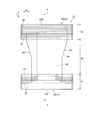
- FIG. 2 is a schematic plan view of the disposable diaper 10 according to this embodiment.
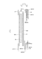
- FIG. 3 is a sectional view taken along the line AA shown in FIG. FIG. 2 and FIG. 3 show an expanded state in which the absorbent article 10 is expanded to a state in which no folds are formed in a state in which the side joint portion 60 described later is expanded. Further, in the cross-sectional view shown in FIG. 3, the respective members are shown separated in the thickness direction T for convenience of description, but they are in contact with each other in the thickness direction T in an actual product.
- the absorbent article 10 has a front-back direction L and a width direction W that are orthogonal to each other.
- the front-rear direction L is defined by the direction extending to the front side of the body and the back side of the body.
- the front-back direction L is a direction extending in the front-back direction in the expanded absorbent article 10.
- the absorbent article 10 has the thickness directions orthogonal to both the front-rear direction L and the width direction W.
- the absorbent article 10 has a front waistline region S1, a back waistline region S2, and a crotch region S3.
- the front waistline region S1 is a region facing the front waistline (abdomen) of the wearer.
- the rear waistline region S2 is a region facing the rear waistline (back part) of the wearer.
- the crotch region S3 is a region located at the crotch of the wearer and arranged between the front waistline region S1 and the rear waistline region S2.
- the crotch region S3 is a region in which leg openings 66 (see FIG. 1) described later are formed.
- the boundary on the crotch region side of the front waistline region S1 is the front end edge of the leg waist opening 66
- the boundary on the crotch region side of the rear waistline region S2 is the rear end edge of the leg waist opening 66.
- the absorbent article 10 may include an absorbent main body 40 and a waist belt 15.
- the waist belt 15 overlaps the absorbent main body 40 in the thickness direction.
- the waist belt 15 may include a front waist belt 20 and a rear waist belt 30.
- the front waist belt 20 is arranged in a region that overlaps the absorbent main body 40 and a region that does not overlap the absorbent main body 40 in the front waistline region S1.
- the rear waist belt 30 is separated from the front waist belt 20 in the front-rear direction L.
- the rear waist belt 30 is arranged in a region that overlaps with the absorbent main body 40 and a region that does not overlap with the absorbent main body 40 in the rear waistline region S2.
- the front waist belt 20 and the rear waist belt 30 may be integrated, and the waist belt 15 may be provided from the front waistline region S1 to the rear waistline region S2.
- the front waist belt 20 includes a front cover sheet 27 arranged on the skin surface side T1 of the absorbent main body 40 and a front first outer cover arranged on the non-skin surface side T2 of the absorbent main body 40.
- the front cover sheet 27, the front first exterior sheet 25, the exterior stretch sheet 28, and the front second exterior sheet 26 are sequentially laminated from the skin surface side T1 toward the non-skin surface side T2. , Joined to each other.
- the front cover sheet 27, the front first exterior sheet 25, and the front second exterior sheet 26 may be formed of separate sheets, or may be formed of the same folded sheet.
- the front cover sheet 27, the front first exterior sheet 25, and the exterior stretch sheet 28 may form the first composite sheet 70A (composite sheet 70) of the present invention.
- the front cover sheet 27 constitutes the first sheet 71 in the first composite sheet 70A of the present invention
- the front first exterior sheet 25 constitutes the second sheet 72 in the first composite sheet 70A of the present invention
- the sheet 28 may form the stretchable member 73 in the first composite sheet 70A of the present invention.
- the composite sheet 70 will be described in detail later.
- the rear waist belt 30 includes a rear cover sheet 37 arranged on the skin surface side T1 of the absorbent main body 40 and a rear first exterior member arranged on the non-skin surface side T2 of the absorbent main body 40.
- the rear cover sheet 37, the rear first exterior sheet 35, the rear thread rubber 38, and the rear second exterior sheet 36 are sequentially laminated from the skin surface side T1 toward the non-skin surface side T2. And may be joined together.
- the rear third exterior sheet 39 may be arranged on the skin side of the rear first exterior sheet 35.
- the rear cover sheet 37, the rear third exterior sheet 39, the rear first exterior sheet 35, the rear thread rubber 38, and the rear second exterior sheet 36 are from the skin surface side T1.
- the layers may be sequentially stacked toward the non-skin surface side T2 and bonded to each other.
- the rear cover sheet 37, the rear first exterior sheet 35, the rear second exterior sheet 36, and the rear third exterior sheet 39 may be separate sheets, or may be the same folded sheet. May be In the present embodiment, the rear second exterior sheet 36 and the rear third exterior sheet 39 are made of the same sheet folded at the waistline opening 62.
- the rear first exterior sheet 35, the rear third exterior sheet 39, and the rear thread rubber 38 may form the second composite sheet 70B (composite sheet 70) of the present invention.
- the rear first exterior sheet 35 constitutes the second sheet 72 in the second composite sheet 70B of the present invention
- the rear third exterior sheet 39 constitutes the first sheet 71 in the second composite sheet 70B of the present invention
- the rear thread rubber 38 may constitute the stretchable member 73 in the second composite sheet 70B of the present invention.
- a side joint 60 may be provided that joins the outer portion of the front waistline region S1 and the outer portion of the rear waistline region S2.
- the side joint portion 60 is defined by a portion in which an outer portion of the front waistline region S1 and an outer portion of the rear waistline region S2 in the width direction W are locked to each other.
- the outer portion in the present invention is a portion that occupies a certain range in the width direction W including the outer edge in the width direction W, and the outer edge is the outer edge in the width direction W.
- the inner portion in the present invention is a portion that occupies a certain range in the width direction W including the inner edge in the width direction W, and the inner edge is the inner edge in the width direction W.
- front end portion and the rear end portion in the present invention are portions that occupy a certain range in the front-rear direction L including the edges in the front-rear direction L, and the front end edge and the rear end edge are edges in the front-rear direction L.
- the outer end portion includes a front end portion and a rear end portion, and the outer end edge includes a front end edge and a rear end edge.
- the absorbent article 10 has a waistline opening 62 through which the wearer's torso passes and a pair of legs into which the wearer's legs are inserted.
- the leg openings 66 are formed.
- the waistline opening 62 may be defined by a front edge S1F of the front waistline region S1 and a rear edge S2R of the rear waistline region S2.
- FIG. 2 shows a state in which the joining at the side joining portion 60 is released and the absorbent article 10 is expanded.
- the side joint portion 60 may extend along the front-rear direction L in each of the front waist belt 20 and the rear waist belt 30.
- the boundary between the front waistline region S1 and the crotch region S3 may be defined by the rear end edge of the side joint portion 60 provided on the front waist belt 20.
- the boundary between the rear waistline region S2 and the crotch region S3 may be defined by the front end edge of the side joint portion 60 provided on the rear waist belt 30.
- a stretchable member that can stretch in the width direction W may be arranged in the front waistline region S1.
- the elastic member may be composed of at least one of the front side thread rubber 22 that can expand and contract in the width direction W and the exterior elastic sheet 28 that can expand and contract in the width direction W.
- the stretchable member may be configured by the front waist belt 20 itself configured by a stretchable sheet, for example.
- An elastic member that can expand and contract in the width direction W may be arranged in the rear waistline region S2.
- the stretchable member may be configured by at least one of the rear thread rubber 38 that is stretchable in the width direction W and the exterior stretchable sheet that is stretchable in the width direction W.
- the stretchable member may be configured by the rear waist belt 30 itself which is configured by a stretchable sheet, for example.
- the absorbent main body 40 is arranged so as to straddle the front waist belt 20 and the rear waist belt 30. That is, the absorbent main body 40 extends over the front waistline region S1, the rear waistline region S2, and the crotch region S3.
- the absorbent body 40 may be configured separately from the front waist belt 20 and the rear waist belt 30. In this case, the absorbent main body 40 may be joined to the front waist belt 20 and the rear waist belt 30 in the front waist region S1 and the back waist region S2, respectively.
- the absorbent body 40 includes at least an absorbent core 50.
- the absorbent core 50 may include, for example, ground pulp or super absorbent polymer (SAP), or a mixture thereof.
- the absorbent core 50 is arranged at least in the crotch region S3.
- the absorbent core 50 may extend in the front-rear direction L from the front waistline region S1 to the rear waistline region S2.
- the absorbent core 50 may be covered by a core wrap.
- the absorbent main body 40 includes a skin surface sheet 42A arranged on the skin surface side of the absorbent core, and a liquid impermeable sheet 41 arranged on the non-skin surface side of the absorbent core 50.
- the main body sheet 42B arranged on the non-skin surface side T2 with respect to the liquid impermeable sheet 41 may be included.
- the composite sheet is a sheet used for absorbent articles.
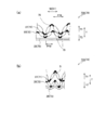
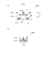
- 4A and 4B are schematic cross-sectional views of the first composite sheet 70A as the composite sheet 70.
- FIG. 4A shows an expanded state
- FIG. 4B shows a contracted state in which the elastic member contracts.
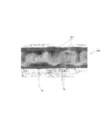
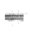
- FIG. 5 is a cross-sectional photograph of the first composite sheet 70A.
- FIG. 6 is a schematic cross-sectional view of the second composite sheet 70B as the composite sheet 70, which is in an expanded state of FIG. 6(a), and FIG. 6(b) is in a contracted state in which the elastic member is contracted. .. Note that, for convenience of description, in FIG.
- FIG. 6 is a cross-sectional photograph of the second composite sheet 70B. 4 and 5, only the first composite sheet 70A is shown, and of the members forming the front waist belt 20, the front second exterior sheet 26 and the front thread rubber 22 are omitted. Further, in FIGS. 6 and 7, only the second composite sheet 70B is shown, and the rear second exterior sheet 36 and the rear cover sheet 37 among the members constituting the rear waist belt 30 are omitted.
- first composite sheet 70A is arranged on the front waist belt 20 and the second composite sheet 70B is arranged on the rear waist belt 30
- the second composite sheet 70B may be disposed on the rear waist belt 30 and the first composite sheet 70A may be disposed on the rear waist belt 30.
- the composite sheet 70 includes a stretchable member 73, a first sheet 71 that is disposed so as to overlap the stretchable member 73, and has a first welded portion 78 in which fibers are heat-welded, and the first sheet 71 and the stretchable member 73.
- the first sheet 71 and the second sheet 72 only need to have fibers, and are made of, for example, a nonwoven fabric.
- the first sheet 71 and the second sheet 72 may be one layer or more, and may be a laminated body 76 like the rear first exterior sheet 35.
- the fibers of the sheets forming the first sheet 71 are welded.
- the first welded portion 78 is a welded portion formed on the first sheet 71 and is not formed on the second sheet 72.
- the fibers of the sheets forming the second sheet 72 are welded to the second welding portion 79.
- the second welded portion 79 is a welded portion formed on the second sheet 72, and is not formed on the first sheet 71. That is, the first welded portion 78 and the second welded portion 79 are provided separately.
- the first welded portion 78 and the second welded portion 79 may be formed by any one of heat welding, ultrasonic welding, and embossing.
- a plurality of each of the first welded portion 78 and the second welded portion 79 are arranged at intervals in the extension/contraction direction D1 of the elastic member 73.
- the pitch P78 of the first welding portion 78 in the expansion/contraction direction is different from the pitch P79 of the second welding portion 79 in the expansion/contraction direction.
- the contraction of the elastic member 73 causes the first sheet 71 and the second sheet 72 to contract in the expansion/contraction direction D1.
- the first sheet 71 is deformed by the contraction of the elastic member 73 so that the spaces between the first welded portions 78 expand in the thickness direction T, respectively.
- a fold is formed on the first sheet 71 between the adjacent first welded portions 78.
- the second sheet 72 is deformed by the contraction of the elastic member 73 so that the spaces between the second welded portions 79 swell in the thickness direction T, respectively.
- the second sheet 72 has folds formed between the adjacent second welded portions 79.
- the first welded portion 78 and the second welded portion 79 are arranged so as to be displaced in the contracting direction. Therefore, compared with the form in which the first welded portion 78 and the second welded portion 79 are all overlapped, the hardness of the welded portion of the composite sheet 70 can be reduced and the touch can be improved. Further, since at least two layers of the first sheet 71 and the second sheet 72 are arranged on the skin surface side T1 of the elastic member 73, the elastic member 73 is prevented from hitting the skin, and the elastic member 73 is suppressed. It is possible to prevent the marks and folds from sticking to the skin.
- the configuration in which the pitch P78 of the first welding portion 78 in the expansion/contraction direction and the pitch P79 of the second welding portion 79 in the expansion/contraction direction are different may be provided over the entire composite sheet, or may be provided partially. It may be. That is, it is a concept including all configurations except that the pitch of the first welded portion 78 and the pitch of the second welded portion are the same in the entire composite sheet 70.
- the pitch P78 of the first welded portion 78 may be longer than the pitch P79 of the second welded portion 79.
- the pitch P79 of the second welded portions 79 is short, and the area between the second welded portions 79 is large.
- the area between the second welded portions 79 is a thinned sheet, which has a low rigidity.
- the pitch P78 of the first welded portions 78 is long and the area between the first welded portions 78 is small.
- the first sheet 71 has less regions of low rigidity, and has higher rigidity as a whole.
- the second sheet 72 having a low overall rigidity is arranged near the stretchable member 73, and fine folds are easily formed on the second sheet 72. Further, since the first sheet 71 is farther from the elastic member 73 than the second sheet 72 and the pitch of the first welded portion 78 is relatively long, it is difficult to follow the fine folds of the second sheet 72, and Is formed such that a relatively large fold bulges from the second sheet 72 in the thickness direction. A space S is formed between the first sheet 71 and the second sheet 72, the cushioning property of the composite sheet 70 is enhanced, and the feel to the touch can be improved. In the present embodiment, in first composite sheet 70A arranged on front waist belt 20, pitch P78 of first welded portion 78 is longer than pitch P79 of second welded portion 79.
- the pitch P78 of the first welded portion 78 may be shorter than the pitch P79 of the second welded portion 79. Since the second sheet 72 is sandwiched between the first sheet 71 and the stretchable member 73, the second sheet 72 can easily follow the small folds of the first sheet 71. In the second sheet 72, not only large folds formed by the second welded portion 79 but also folds that follow small folds formed by the first welded portion 78 are easily formed. As a result, the folds of the composite sheet 70 are likely to be uniform, the folds are prevented from locally touching the skin, and the touch can be improved. Further, since the pitch P78 of the first welded portions 78 is short, the area between the first welded portions 78 increases.
- the area between the first welded portions 78 is a portion having low rigidity.
- the pitch of the second welded portions is long and the area between the second welded portions is small.
- the first sheet has many regions with low rigidity, and the rigidity is low as a whole.
- the first sheet 71 which has a relatively low rigidity, is likely to follow the second sheet 72, and the folds of the composite sheet are likely to be uniform.
- pitch P78 of first welded portion 78 is shorter than pitch P79 of second welded portion 79.
- the composite sheet 70 has a cushioning property, and it is particularly preferable to dispose the composite sheet 70 in a region where the touch is desired to be improved.
- the composite sheet 70 is arranged on the skin-side surface of the front waist belt 20 and the skin-side surface of the rear waist belt 30.
- a front cover sheet 27 is arranged on the skin side surface of the front waist belt 20, and a rear cover sheet 37 is arranged on the skin side surface of the rear waist belt 30. Folds are formed on the surface of the waist belt that touches the skin, and the feel of the waist can be improved.
- the composite sheet 70 may be arranged on the leg flaps arranged along the circumference of the wearer's legs. According to the modified example, the feel of the wearer around the legs can be improved.
- Extending/contracting direction D1 of the elastic member in the composite sheet 70 is along the width direction W, and a plurality of first welding portions 78 and second welding portions 79 are arranged at intervals in the width direction W. Therefore, the folds extending in the front-rear direction L are formed on the composite sheet 70.
- the folds of the waist belt 15 can prevent the waist belt 15 from buckling in the front-rear direction L. It is possible to suppress the local increase in the contact with the skin due to blistering and improve the touch.
- one of the composite sheets 70 arranged on the front waist belt 20 and the rear waist belt 30 has the pitch P78 of the first welded portion 78 longer than the pitch of the second welded portion 79.
- the pitch P78 of the first welding portion 78 is shorter than the pitch P79 of the second welding portion 79.
- the composite sheet arranged on the rear waist belt 30 is The pitch P78 of the first welded portion 78 is shorter than the pitch P79 of the second welded portion 79.
- the pitch P78 of the first welded portion 78 is longer than the pitch P79 of the second welded portion 79.
- the first composite sheet 70A may be arranged on the front waist belt 20. Generally, the abdomen has softer skin than the back and is more likely to be traced by folds. However, since the first composite sheet 70A has a high cushioning property, it is possible to soften the contact with the skin and suppress the formation of marks due to folds.
- the elastic member 73 of the first composite sheet 70A may have a sheet shape.
- the stretchable member 73 of the first composite sheet 70A of the present embodiment is the exterior stretchable sheet 28.
- the sheet-shaped stretchable member 73 allows the first sheet 71 and the second sheet 72 to be contracted on the surface. Therefore, the folds due to the second welded portion 79 and the folds due to the first welded portion 78 are easily formed, the first sheet 71 is easily lifted up from the second sheet 72, and the cushioning property is easily enhanced.
- the pitch P78 of the first welded portion 78 is shorter than the pitch P79 of the second welded portion 79.
- the second composite sheet 70B may be arranged on the rear waist belt 30. The back is likely to be subject to body pressure when lying down. Since the folds of the second composite sheet tend to be uniform, when the body pressure is applied, the force is dispersed by the uniform folds, and it is possible to suppress the folds from locally hitting the skin and improve the touch.
- the stretchable members 73 of the second composite sheet 70B may be thread-like, and a plurality of stretchable members 73 may be arranged at intervals in the width direction W.
- the elastic members 73 of the second composite sheet 70B of the present embodiment are the rear thread rubbers 38, and a plurality of elastic members 73 are arranged at intervals in the width direction W.
- the first and second sheets can be contracted at points by the thread-like elastic member. Since the first sheet and the second sheet both shrink locally, the folds of the composite sheet tend to be more uniform.
- the method for manufacturing the composite sheet includes a first sheet welding step, a second sheet welding step, and a laminating step.
- the first sheet welding step the first welding portion is formed on the first sheet 71 at intervals in the transport direction.
- the first welding portion may be formed on the first sheet continuous body in which the first sheet 71 is continuous in the transport direction.
- a second welding portion is formed on the second sheet with an interval in the transport direction.
- the second welded portions are formed at a pitch in the transport direction that is different from a pitch in the transport direction of the first welded portions.
- the second welding portion may be formed on the second sheet continuous body in which the second sheet 72 is continuous in the transport direction.
- the laminating step is performed after the first sheet welding step and the second sheet welding step.
- the second sheet is arranged between the stretchable member 73 stretched in the transport direction and the first sheet.
- the first sheet 71, the second sheet 72 and the stretchable member 73 are joined to each other by an adhesive means such as an adhesive.
- the first sheet, the second sheet, and the elastic member are formed. Since they are laminated, the pitch of the first welded portion 78 and the pitch P79 of the second welded portion 79 can be made different. Since the pitch of the first welded portion and the pitch of the second welded portion are different, the first welded portion and the second welded portion are displaced in the shrinking direction. Therefore, as compared with the form in which the first welded portion and the second welded portion are all overlapped with each other, it is possible to obtain a composite sheet with improved touch.
Landscapes
- Health & Medical Sciences (AREA)
- Epidemiology (AREA)
- Engineering & Computer Science (AREA)
- Biomedical Technology (AREA)
- Heart & Thoracic Surgery (AREA)
- Vascular Medicine (AREA)
- Life Sciences & Earth Sciences (AREA)
- Animal Behavior & Ethology (AREA)
- General Health & Medical Sciences (AREA)
- Public Health (AREA)
- Veterinary Medicine (AREA)
- Absorbent Articles And Supports Therefor (AREA)
Abstract
襞を有する複合シートにおいて肌触りをより向上させる。複合シート(70)は、吸収性物品に用いられる複合シートであって、伸縮性部材(73)と、伸縮性部材と重なって配置され、繊維が溶着した第1溶着部(78)を有する第1シート(71)と、第1シートと伸縮性部材の間に配置され、繊維が溶着した第2溶着部(79)を有する第2シート(72)と、を備える。第1溶着部及び第2溶着部のそれぞれは、伸縮性部材の伸縮方向において間隔を空けて複数配置されている。第1溶着部の伸縮方向のピッチ(P78)は、第2溶着部の伸縮方向のピッチ(P79)と異なる。
Description
本発明は、吸収性物品等に用いられる複合シート及び複合シートを有する吸収性物品及び複合シートの製造方法に関する。
特許文献1には、吸収性物品のウエストベルトを構成する複合シートが開示されている。特許文献1の複合シートは、内層シートと、内層シートと積層された外層シートと、内層シートと外層シートの間に配置された糸状の伸縮性部材と、内層シートと外層シートを接合した接合部と、を有している。伸縮性部材は、幅方向に延び、かつ前後方向に間隔を空けて複数配置されている。接合部は、幅方向及び前後方向に間隔を空けて複数配置されている。
特許文献1の複合シートの接合部は、熱溶着によって内層シートと外層シートを接合している。伸縮性部材が収縮することにより、隣り合う接合部間のシートが、それぞれ厚み方向に膨らむように変形して、隣接する接合部間にシートからなる襞が形成でされる。襞によって複合シートの肌触りが向上する。しかし、近年、吸収性物品における肌触りに対する要求は、高まっている。よって、襞を有する複合シートにおいて肌触りをより向上させることを目的とする。
一態様に係る複合シートは、吸収性物品に用いられる複合シートであって、伸縮性部材と、前記伸縮性部材と重なって配置され、繊維が溶着した第1溶着部を有する第1シートと、前記第1シートと前記伸縮性部材の間に配置され、繊維が溶着した第2溶着部を有する第2シートと、を備え、前記第1溶着部及び前記第2溶着部のそれぞれは、前記伸縮性部材の伸縮方向において間隔を空けて複数配置されており、前記第1溶着部の前記伸縮方向のピッチは、前記第2溶着部の前記伸縮方向のピッチと異なる。
一態様に係る吸収性物品は、前後方向及び前記前後方向に直交する幅方向と、前胴回り域と、後胴回り域と、前記前胴回り域と前記後胴回り域との間に配置された股下域と、前記股下域、前記前胴回り域及び前記後胴回り域に跨がって配置された吸収性本体と、前記前胴回り域において前記吸収性本体と厚み方向に重なる前ウエストベルトと、前記後胴回り域において前記吸収性本体と厚み方向に重なる後ウエストベルトと、前記前ウエストベルトの肌面側の表面及び前記後ウエストベルトの肌面側の表面に配置された複合シートと、を有する吸収性物品であって、前記複合シートは、少なくとも前記幅方向に伸縮する前記伸縮性部材と、前記伸縮性部材の前記肌面側に配置され、繊維が溶着した第1溶着部を有する第1シートと、前記第1シートと前記伸縮性部材の間に配置され、繊維が溶着した第2溶着部を有する第2シートと、を備え、前記第1溶着部及び前記第2溶着部のそれぞれは、前記幅方向において間隔を空けて複数配置されており、前記第1溶着部の前記幅方向のピッチは、前記第2溶着部の前記幅方向のピッチと異なる。
一態様に係る複合シートの製造方法は、搬送方向に間隔を空けて第1シートに第1溶着部を形成する第1シート溶着工程と、前記搬送方向に間隔を空けて第2シートに第2溶着部を形成する第2シート溶着工程と、前記第1シート溶着工程及び前記第2シート溶着工程の後に、前記搬送方向に伸長させた伸縮性部材と前記第1シートとの間に前記第2シートに配置する積層工程と、を有し、前記第2シート溶着工程は、前記第1溶着部の前記搬送方向のピッチと異なる前記搬送方向のピッチで前記第2溶着部を形成する。
(1)実施形態の概要
本明細書及び添付図面の記載により、少なくとも以下の事項が明らかとなる。
一態様に係る複合シートは、吸収性物品に用いられる複合シートであって、伸縮性部材と、前記伸縮性部材と重なって配置され、繊維が溶着した第1溶着部を有する第1シートと、前記第1シートと前記伸縮性部材の間に配置され、繊維が溶着した第2溶着部を有する第2シートと、を備え、前記第1溶着部及び前記第2溶着部のそれぞれは、前記伸縮性部材の伸縮方向において間隔を空けて複数配置されており、前記第1溶着部の前記伸縮方向のピッチは、前記第2溶着部の前記伸縮方向のピッチと異なる。第1シートは、伸縮性部材の収縮によって第1溶着部間がそれぞれ厚み方向に膨らむように変形する。よって、第1シートには、隣接する第1溶着部間に襞が形成される。また、第2シートは、伸縮性部材の収縮によって第2溶着部間がそれぞれ厚み方向に膨らむように変形する。よって、第2シートには、隣接する第2溶着部間に襞が形成される。第1溶着部のピッチと第2溶着部のピッチが異なるため、第1溶着部が第2溶着部が収縮方向にずれて配置される。そのため、第1溶着部と第2溶着部が全て重なっている形態と比較して、複合シートの溶着部による硬さを低減し、肌触りを向上できる。
好ましい一態様によれば、前記第1溶着部の前記ピッチは、前記第2溶着部の前記ピッチよりも長くてよい。本態様によれば、第2溶着部のピッチが短く、第2溶着部間の領域が多くなる。第2溶着部間の領域は、シートが引き延ばされて薄くなっており、剛性が低い部分となる。一方、第1溶着部のピッチが長く、第1シートにおける第1溶着部間の領域が少ない。第1シートは、第2シートと比較して、剛性が低い領域が少なく、全体として剛性が高くなる。全体の剛性が低い第2シートが伸縮性部材の近くに配置されており、第2シートには、細かい襞が形成されやすい。また、第1シートが第2シートよりも伸縮性部材から離れ、かつ第1溶着部のピッチが比較的長いため、第1シートは、第2シートの細かい襞に沿いにくく、第1シートには、比較的大きい襞が第2シートから厚み方向に膨らむように形成される。第1シートと第2シートの間に空間が形成され、複合シートのクッション性が高まり、肌触りを向上できる。
他の態様によれば、前記第1溶着部のピッチは、前記第2溶着部のピッチよりも短くてよい。本態様によれば、第2シートは、第1シートと伸縮性部材によって挟まれているため、第1シートの小さい襞に追従し易くなる。そのため、第2シートには、第2溶着部による大きな襞のみならず、第1溶着部による小さい襞に追従する襞が形成され易い。その結果、複合シートの襞が均一になりやすく、襞が局所的に肌にあたることを抑制し、肌触りを向上できる。また、第1溶着部のピッチが短いため、第1溶着部間の領域が多くなる。第1溶着部間の領域は、シートが引き延ばされて薄くなっており、剛性が低い部分となる。一方、第2溶着部のピッチが長く、第2溶着部間の領域が少ない。第1シートは、第2シートと比較して、剛性が低い領域が多く、全体として剛性が低くなる。剛性が比較的低い第1シートが第2シートに沿い易く、複合シートの襞が均一になり易い。
一態様に係る吸収性物品は、前後方向及び前記前後方向に直交する幅方向と、前胴回り域と、後胴回り域と、前記前胴回り域と前記後胴回り域との間に配置された股下域と、前記股下域、前記前胴回り域及び前記後胴回り域に跨がって配置された吸収性本体と、前記前胴回り域において前記吸収性本体と厚み方向に重なる前ウエストベルトと、前記後胴回り域において前記吸収性本体と厚み方向に重なる後ウエストベルトと、前記前ウエストベルトの肌面側の表面及び前記後ウエストベルトの肌面側の表面に配置された複合シートと、を有する吸収性物品であって、前記複合シートは、少なくとも前記幅方向に伸縮する前記伸縮性部材と、前記伸縮性部材の前記肌面側に配置され、繊維が溶着した第1溶着部を有する第1シートと、前記第1シートと前記伸縮性部材の間に配置され、繊維が溶着した第2溶着部を有する第2シートと、を備え、前記第1溶着部及び前記第2溶着部のそれぞれは、前記幅方向において間隔を空けて複数配置されており、前記第1溶着部の前記幅方向のピッチは、前記第2溶着部の前記幅方向のピッチと異なる。本態様によれば、ウエストベルトの肌に触れる面に襞が形成され、腰周りに対する肌触りを向上できる。また、伸縮性部材が幅方向に伸縮し、かつ第1溶着部及び第2溶着部のそれぞれが幅方向において間隔を空けて複数配置されているため、複合シートには、前後方向に延びる襞が形成される。ウエストベルトの襞によってウエストベルトの前後方向のたくれを抑制できる。たくれによって肌への当たりが局所的に高くなることを抑制し、肌触りを向上できる。また、伸縮性部材よりも肌面側に、第1シート及び第2シートの少なくとも2層が配置されるため、伸縮性部材による肌への当たりを抑制し、伸縮性部材の跡や襞の跡が肌に付くことを抑制できる。
好ましい一態様によれば、前記前ウエストベルトに配置された複合シート及び前記後ウエストベルトに配置された複合シートのうち一方の複合シートは、前記第1溶着部のピッチが前記第2溶着部のピッチよりも長く、前記前ウエストベルトに配置された複合シート及び前記後ウエストベルトに配置された複合シートのうち他方の複合シートは、前記第1溶着部のピッチが前記第2溶着部のピッチよりも短くてよい。本態様によれば、前ウエストベルトにおける襞と後ウエストベルトの襞とを異ならせ、腹部及び背部のそれぞれに対して適切にウエストベルトを当てて、肌触りを向上できる。
好ましい一態様によれば、前記複合シートは、前記第1溶着部の前記ピッチが前記第2溶着部の前記ピッチよりも長い第1複合シートを有し、前記第1複合シートは、前記前ウエストベルトに配置されてよい。一般的に、腹部は、背部よりも皮膚が柔らかく、襞による跡が付きやすい。しかし、第1複合シートのクッション性が高いため、肌への当たりを和らげ、襞による跡がつくことを抑制できる。
好ましい一態様によれば、前記第1複合シートの前記伸縮性部材は、シート状であってよい。本態様によれば、シート状の伸縮性部材によって第1シート及び第2シートを面で収縮させることができる。よって、第2溶着部による襞と第1溶着部による襞がそれぞれ形成されやすくなり、第2シートに対して第1シートが浮き上がりやすくなり、クッション性がより高くなり易い。
好ましい一態様によれば、前記複合シートは、前記第1溶着部の前記ピッチが前記第2溶着部の前記ピッチよりも短い第2複合シートを有し、前記第2複合シートは、前記後ウエストベルトに配置されてよい。背部は、寝た姿勢等において体圧を受けやすい。第2複合シートの襞が均一になりやすいため、体圧を受けた際に均一な襞によって力を分散するとともに、襞が局所的に肌にあたることを抑制し、肌触りを向上できる。
好ましい一態様によれば、前記第2複合シートの前記伸縮性部材は、糸状であって、前記幅方向に間隔を空けて複数配置されてよい。本態様によれば、糸状の伸縮性部材によって第1シート及び第2シートを点で収縮させることができる。第1シートと第2シートが共に局所的に収縮することで複合シートの襞がより均一になりやすい。
一態様に係る複合シートの製造方法は、搬送方向に間隔を空けて第1シートに第1溶着部を形成する第1シート溶着工程と、前記搬送方向に間隔を空けて第2シートに第2溶着部を形成する第2シート溶着工程と、前記第1シート溶着工程及び前記第2シート溶着工程の後に、前記搬送方向に伸長させた伸縮性部材と前記第1シートとの間に前記第2シートに配置する積層工程と、を有し、前記第2シート溶着工程は、前記第1溶着部の前記搬送方向のピッチと異なる前記搬送方向のピッチで前記第2溶着部を形成する。本態様によれば、第1シートの第1溶着部と、第2シートの第2溶着部と、をそれぞれ形成した後に、第1シート、第2シート及び伸縮性部材を積層しているため、第1溶着部のピッチと第2溶着部のピッチを異ならせることができる。第1溶着部のピッチと第2溶着部のピッチが異なるため、第1溶着部が第2溶着部が収縮方向にずれて配置される。そのため、第1溶着部と第2溶着部が全て重なっている形態と比較して、肌触りが向上された複合シートを得ることができる。
(2)吸収性物品の全体概略構成
以下、図面を参照して、実施形態に係る吸収性物品について説明する。なお、以下の図面の記載において、同一又は類似の部分には、同一又は類似の符号を付している。ただし、図面は模式的なものであり、各寸法の比率等は現実のものとは異なることに留意すべきである。したがって、具体的な寸法等は、以下の説明を参酌して判断すべきである。また、図面相互間においても互いの寸法の関係や比率が異なる部分が含まれ得る。吸収性物品は、テープ型であってもよいし、パンツ型であってもよい。吸収性物品は、使い捨ておむつであってもよいし、ショーツ型の生理用ナプキンであってよい。実施形態の吸収性物品は、パンツ型の使い捨ておむつである。図1は、本実施形態に係る吸収性物品10の模式正面図である。図2は、本実施形態に係る使い捨ておむつ10の模式平面図である。図3は、図2に示すA-A線に沿った断面図である。図2及び図3では、後述するサイド接合部60を展開した状態において吸収性物品10を襞が形成されない状態まで伸長させた伸長状態を示している。また、図3に示す断面図では、説明の便宜上、各部材を厚み方向Tにおいて離間して示しているが、実際の製品においては厚み方向Tに接している。
以下、図面を参照して、実施形態に係る吸収性物品について説明する。なお、以下の図面の記載において、同一又は類似の部分には、同一又は類似の符号を付している。ただし、図面は模式的なものであり、各寸法の比率等は現実のものとは異なることに留意すべきである。したがって、具体的な寸法等は、以下の説明を参酌して判断すべきである。また、図面相互間においても互いの寸法の関係や比率が異なる部分が含まれ得る。吸収性物品は、テープ型であってもよいし、パンツ型であってもよい。吸収性物品は、使い捨ておむつであってもよいし、ショーツ型の生理用ナプキンであってよい。実施形態の吸収性物品は、パンツ型の使い捨ておむつである。図1は、本実施形態に係る吸収性物品10の模式正面図である。図2は、本実施形態に係る使い捨ておむつ10の模式平面図である。図3は、図2に示すA-A線に沿った断面図である。図2及び図3では、後述するサイド接合部60を展開した状態において吸収性物品10を襞が形成されない状態まで伸長させた伸長状態を示している。また、図3に示す断面図では、説明の便宜上、各部材を厚み方向Tにおいて離間して示しているが、実際の製品においては厚み方向Tに接している。
吸収性物品10は、互いに直交する前後方向L及び幅方向Wを有する。前後方向Lは、身体前側と身体後側とに延びる方向によって規定される。言い換えると、前後方向Lは、展開された吸収性物品10において前後に延びる方向である。また、吸収性物品10は、前後方向Lと幅方向Wの両方の直交する厚み方向を有する。吸収性物品10は、前胴回り域S1と、後胴回り域S2と、股下域S3と、を有する。前胴回り域S1は、着用者の前胴回り(腹部)に対向する領域である。後胴回り域S2は、着用者の後胴回り(背部)に対向する領域である。股下域S3は、着用者の股下に位置し、前胴回り域S1と後胴回り域S2との間に配置された領域である。股下域S3は、後述する脚回り開口部66(図1参照)が形成された領域である。前胴回り域S1の股下域側の境界は、脚回り開口部66の前端縁であり、後胴回り域S2の股下域側の境界は、脚回り開口部66の後端縁である。
吸収性物品10は、吸収性本体40と、ウエストベルト15と、を有していてよい。ウエストベルト15は、吸収性本体40と厚み方向に重なっている。ウエストベルト15は、前ウエストベルト20と、後ウエストベルト30と、を有してよい。前ウエストベルト20は、前胴回り域S1において、吸収性本体40と重なる領域と、吸収性本体40と重ならない領域と、に配置されている。後ウエストベルト30は、前ウエストベルト20と前後方向Lに離間している。後ウエストベルト30は、後胴回り域S2において、吸収性本体40と重なる領域と、吸収性本体40と重ならない領域と、に配置されている。なお、他の実施形態において、ウエストベルト15は、前ウエストベルト20及び後ウエストベルト30が一体化され、かつ前胴回り域S1から後胴回り域S2に亘って設けられていてもよい。
図3に示すように、前ウエストベルト20は、吸収性本体40の肌面側T1に配置された前カバーシート27と、吸収性本体40の非肌面側T2に配置された前第1外装シート25と、前第1外装シート25の非肌面側T2に位置する前第2外装シート26と、前第1外装シート25と前第2外装シート26の間に配置された外装伸縮シート28と、を有してよい。吸収性本体40と重ならない領域では、前カバーシート27、前第1外装シート25、外装伸縮シート28及び前第2外装シート26が肌面側T1から非肌面側T2に向かって順に積層され、互いに接合されている。なお、前カバーシート27、前第1外装シート25及び前第2外装シート26は、別々のシートによって構成されていてもよいし、折り返された同一のシートによって構成されていてもよい。前カバーシート27、前第1外装シート25及び外装伸縮シート28は、本発明の第1複合シート70A(複合シート70)を構成してよい。前カバーシート27は、本発明の第1複合シート70Aにおける第1シート71を構成し、前第1外装シート25は、本発明の第1複合シート70Aにおける第2シート72を構成し、外装伸縮シート28は、本発明の第1複合シート70Aにおける伸縮性部材73を構成してよい。なお、複合シート70については、後述にて詳細に説明する。
図3に示すように、後ウエストベルト30は、吸収性本体40の肌面側T1に配置された後カバーシート37と、吸収性本体40の非肌面側T2に配置された後第1外装シート35と、後第1外装シート35の非肌面側T2に位置する後第2外装シート36と、後第1外装シート35と後第2外装シート36の間に配置された後側糸ゴム38と、を有してよい。吸収性本体40と重ならない領域では、後カバーシート37、後第1外装シート35、後側糸ゴム38及び後第2外装シート36が肌面側T1から非肌面側T2に向かって順に積層され、互いに接合されてよい。また、後第1外装シート35の肌面側には、後第3外装シート39が配置されてよい。後第3外装シート39が配置された領域では、後カバーシート37、後第3外装シート39、後第1外装シート35、後側糸ゴム38及び後第2外装シート36が肌面側T1から非肌面側T2に向かって順に積層され、互いに接合されてよい。なお、後カバーシート37、後第1外装シート35、後第2外装シート36及び後第3外装シート39は、別々のシートによって構成されていてもよいし、折り返された同一のシートによって構成されていてもよい。本実施の形態では、後第2外装シート36及び後第3外装シート39は、胴回り開口部62において折り返された同一のシートによって構成されている。
後第1外装シート35、後第3外装シート39及び後側糸ゴム38は、本発明の第2複合シート70B(複合シート70)を構成してよい。後第1外装シート35は、本発明の第2複合シート70Bにおける第2シート72を構成し、後第3外装シート39は、本発明の第2複合シート70Bにおける第1シート71を構成し、後側糸ゴム38は、本発明の第2複合シート70Bにおける伸縮性部材73を構成してよい。
図1に示すように、前胴回り域S1の外側部と、後胴回り域S2の外側部と、を接合したサイド接合部60が設けられていてよい。サイド接合部60は、前胴回り域S1の外側部と、幅方向Wにおける後胴回り域S2の外側部と、を互いに係止した部分によって規定される。なお、本発明における外側部とは、幅方向Wにおける外縁を含む幅方向Wに一定の範囲を占める部分であり、外側縁とは、幅方向Wにおける外縁である。本発明における内側部とは、幅方向Wにおける内縁を含む幅方向Wに一定の範囲を占める部分であり、内側縁とは、幅方向Wにおける内縁である。また、本発明における前端部及び後端部は、前後方向Lにおける縁を含む前後方向Lに一定の範囲を占める部分であり、前端縁及び後端縁は、前後方向Lにおける縁である。外端部は、前端部及び後端部を含んでおり、外端縁は、前端縁及び後端縁を含んでいる。
図1に示すように、サイド接合部60が形成された状態で、吸収性物品10には、着用者の胴が通される胴回り開口部62と、着用者の脚がそれぞれ挿入される一対の脚回り開口部66と、が形成される。胴回り開口部62は、前胴回り域S1の前端縁S1Fと、後胴回り域S2の後端縁S2Rとによって規定されていてよい。ここで、図2は、サイド接合部60における接合を解除し、吸収性物品10を展開した状態を示している。サイド接合部60は、前ウエストベルト20及び後ウエストベルト30のそれぞれにおいて、前後方向Lに沿って延びていてよい。パンツ型の吸収性物品においては、前胴回り域S1と股下域S3との境界は、前ウエストベルト20に設けられたサイド接合部60の後端縁によって規定されていてよい。同様に、後胴回り域S2と股下域S3との境界は、後ウエストベルト30に設けられたサイド接合部60の前端縁によって規定されていてよい。
図3に示すように、前胴回り域S1には、幅方向Wに伸縮可能な伸縮性部材が配置されてよい。伸縮性部材は、幅方向Wに伸縮可能な前側糸ゴム22、及び幅方向Wに伸縮可能な外装伸縮シート28の少なくともいずれかによって構成されていてよい。この代わりに、伸縮性部材は、例えば伸縮可能なシートにより構成された前ウエストベルト20自体によって構成されていてもよい。後胴回り域S2には、幅方向Wに伸縮可能な伸縮性部材が配置されてよい。伸縮性部材は、幅方向Wに伸縮可能な後側糸ゴム38、及び幅方向Wに伸縮可能な外装伸縮シートの少なくともいずれかによって構成されていてよい。この代わりに、伸縮性部材は、例えば伸縮可能なシートにより構成された後ウエストベルト30自体によって構成されていてもよい。
吸収性本体40は、前ウエストベルト20と後ウエストベルト30とに跨って配置されている。すなわち、吸収性本体40は、前胴回り域S1、後胴回り域S2及び股下域S3にわたって延びている。吸収性本体40は、前ウエストベルト20及び後ウエストベルト30とは別体として構成されていてよい。この場合、吸収性本体40は、前胴回り域S1及び後胴回り域S2において、それぞれ前ウエストベルト20及び後ウエストベルト30と接合されていてよい。 吸収性本体40は、少なくとも吸収コア50を含んでいる。吸収コア50は、例えば粉砕パルプもしくは高吸収性ポリマー(SAP)、又はこれらの混合物を含んでいてよい。吸収コア50は、少なくとも股下域S3に配置されている。好ましくは、吸収コア50は、前後方向Lにおいて、前胴回り域S1から後胴回り域S2にわたって延びていてよい。吸収コア50は、コアラップによって覆われていてよい。さらに、図3に示すように、吸収性本体40は、吸収コアの肌面側に配置された肌面シート42Aと、吸収コア50の非肌面側に配置された液不透過シート41と、液不透過シート41よりも非肌面側T2に配置された本体シート42Bと、を有していてよい。
(3)複合シートの構成
次いで、図4から図7に基づいて、複合シート70の構成について詳細に説明する。複合シートは、吸収性物品に用いられるシートである。図4は、複合シート70としての第1複合シート70Aの模式断面図であり、図4(a)は、伸長状態であり、図4(b)は、伸縮性部材が収縮した収縮状態を示している。また、図5は、第1複合シート70Aの断面写真である。図6は、複合シート70としての第2複合シート70Bの模式断面図であり、図6(a)伸長状態であり、図6(b)は、伸縮性部材が収縮した収縮状態を示している。なお、説明の便宜上、図6においては、積層体76からなる後第1外装シート35を1層にて図示する。また、図4及び図6は、複合シートを模式的に示した図であり、溶着部の形状等、複合シート全体の形状は、当該図面に限定されない。また、図7は、第2複合シート70Bの断面写真である。図4及び図5では、第1複合シート70Aのみを示しており、前ウエストベルト20を構成する部材のうち、前第2外装シート26及び前側糸ゴム22を省略している。また、図6及び図7では、第2複合シート70Bのみを示しており、後ウエストベルト30を構成する部材のうち、後第2外装シート36及び後カバーシート37を省略している。なお、以下の説明においては、前ウエストベルト20に第1複合シート70Aが配置され、後ウエストベルト30に第2複合シート70Bが配置された構成を説明するが、変形例において、前ウエストベルト20に第2複合シート70Bが配置されていてもよいし、後ウエストベルト30に第1複合シート70Aが配置されていてもよい。
次いで、図4から図7に基づいて、複合シート70の構成について詳細に説明する。複合シートは、吸収性物品に用いられるシートである。図4は、複合シート70としての第1複合シート70Aの模式断面図であり、図4(a)は、伸長状態であり、図4(b)は、伸縮性部材が収縮した収縮状態を示している。また、図5は、第1複合シート70Aの断面写真である。図6は、複合シート70としての第2複合シート70Bの模式断面図であり、図6(a)伸長状態であり、図6(b)は、伸縮性部材が収縮した収縮状態を示している。なお、説明の便宜上、図6においては、積層体76からなる後第1外装シート35を1層にて図示する。また、図4及び図6は、複合シートを模式的に示した図であり、溶着部の形状等、複合シート全体の形状は、当該図面に限定されない。また、図7は、第2複合シート70Bの断面写真である。図4及び図5では、第1複合シート70Aのみを示しており、前ウエストベルト20を構成する部材のうち、前第2外装シート26及び前側糸ゴム22を省略している。また、図6及び図7では、第2複合シート70Bのみを示しており、後ウエストベルト30を構成する部材のうち、後第2外装シート36及び後カバーシート37を省略している。なお、以下の説明においては、前ウエストベルト20に第1複合シート70Aが配置され、後ウエストベルト30に第2複合シート70Bが配置された構成を説明するが、変形例において、前ウエストベルト20に第2複合シート70Bが配置されていてもよいし、後ウエストベルト30に第1複合シート70Aが配置されていてもよい。
複合シート70は、伸縮性部材73と、伸縮性部材73と重なって配置され、繊維が熱溶着された第1溶着部78を有する第1シート71と、第1シート71と伸縮性部材73の間に配置され、繊維が熱溶着された第2溶着部79を有する第2シート72と、を備える。第1シート71及び第2シート72は、繊維を有していればよく、例えば、不織布によって構成される。第1シート71及び第2シート72は、1層以上であればよく、後第1外装シート35のように積層体76であってもよい。
第1溶着部78は、第1シート71を構成するシートの繊維が溶着している。第1溶着部78は、第1シート71に形成された溶着部であって、第2シート72には形成されていない。また、第2溶着部79は、第2シート72を構成するシートの繊維が溶着している。第2溶着部79は、第2シート72に形成された溶着部であって、第1シート71には形成されていない。すなわち、第1溶着部78と第2溶着部79は、別々に設けられている。第1溶着部78及び第2溶着部79は、熱溶着、超音波溶着及びエンボス加工のいずれかによって形成されてよい。第1溶着部78及び第2溶着部79のそれぞれは、伸縮性部材73の伸縮方向D1において間隔を空けて複数配置されている。第1溶着部78の伸縮方向のピッチP78は、第2溶着部79の伸縮方向のピッチP79と異なる。
図4(b)及び図6(b)に示すように、複合シート70は、伸縮性部材73の収縮によって第1シート71と第2シート72が伸縮方向D1に収縮する。このとき、第1シート71は、伸縮性部材73の収縮によって第1溶着部78間がそれぞれ厚み方向Tに膨らむように変形する。第1シート71には、隣接する第1溶着部78間に襞が形成される。また、第2シート72は、伸縮性部材73の収縮によって第2溶着部79間がそれぞれ厚み方向Tに膨らむように変形する。第2シート72には、隣接する第2溶着部79間に襞が形成される。第1溶着部78のピッチP78と第2溶着部79のピッチP79が異なるため、第1溶着部78が第2溶着部79が収縮方向にずれて配置される。そのため、第1溶着部78と第2溶着部79が全て重なっている形態と比較して、複合シート70の溶着部による硬さを低減し、肌触りを向上できる。また、伸縮性部材73よりも肌面側T1に、第1シート71及び第2シート72の少なくとも2層が配置されるため、伸縮性部材73による肌への当たりを抑制し、伸縮性部材73の跡や襞の跡が肌に付くことを抑制できる。なお、第1溶着部78の伸縮方向のピッチP78と第2溶着部79の伸縮方向のピッチP79とが異なる構成は、複合シートの全体に亘って設けられていてもよいし、一部において設けられていてもよい。すなわち、第1溶着部78のピッチと第2溶着部のピッチが複合シート70の全体で一致する以外の構成を全て含む概念である。
図4及び図5に示すように、第1溶着部78のピッチP78は、第2溶着部79のピッチP79よりも長くてよい。第2溶着部79のピッチP79が短く、第2溶着部79間の領域が多くなる。第2溶着部79間の領域は、シートが引き延ばされて薄くなっており、剛性が低い部分となる。一方、第1溶着部78のピッチP78が長く、第1溶着部78間の領域が少ない。第1シート71は、第2シート72と比較して、剛性が低い領域が少なく、全体として剛性が高くなる。全体の剛性が低い第2シート72が伸縮性部材73の近くに配置されており、第2シート72には、細かい襞が形成されやすい。また、第1シート71が第2シート72よりも伸縮性部材73から離れ、かつ第1溶着部78のピッチが比較的長いため、第2シート72の細かい襞に沿いにくく、第1シート71には、比較的大きい襞が第2シート72から厚み方向に膨らむように形成される。第1シート71と第2シート72の間に空間Sが形成され、複合シート70のクッション性が高まり、肌触りを向上できる。なお、本実施の形態では、前ウエストベルト20に配置された第1複合シート70Aにおいて、第1溶着部78のピッチP78は、第2溶着部79のピッチP79よりも長い。
また、図6及び図7に示すように、第1溶着部78のピッチP78は、第2溶着部79のピッチP79よりも短くてよい。第2シート72は、第1シート71と伸縮性部材73によって挟まれているため、第1シート71の小さい襞に追従し易くなる。第2シート72には、第2溶着部79による大きな襞のみならず、第1溶着部78による小さい襞に追従する襞が形成され易い。その結果、複合シート70の襞が均一になりやすく、襞が局所的に肌にあたることを抑制し、肌触りを向上できる。また、第1溶着部78のピッチP78が短いため、第1溶着部78間の領域が多くなる。第1溶着部78間の領域は、剛性が低い部分となる。一方、第2溶着部のピッチが長く、第2溶着部間の領域が少ない。第1シートは、第2シートと比較して、剛性が低い領域が多く、全体として剛性が低くなる。剛性が比較的低い第1シート71が第2シート72に沿い易く、複合シートの襞が均一になり易い。なお、本実施の形態では、後ウエストベルト30に配置された第2複合シート70Bにおいて、第1溶着部78のピッチP78は、第2溶着部79のピッチP79よりも短い。
(4)複合シートを有する吸収性物品の構成
次いで、上述の複合シート70を有する吸収性物品10の構成について説明する。複合シート70はクッション性を有しており、特に肌触りを向上させたい領域に配置することが好ましい。複合シート70は、前ウエストベルト20の肌面側の表面及び後ウエストベルト30の肌面側の表面に配置されている。前ウエストベルト20の肌面側の表面には、前カバーシート27が配置され、後ウエストベルト30の肌面側の表面には、後カバーシート37が配置されている。ウエストベルトの肌に触れる面に襞が形成され、腰周りに対する肌触りを向上できる。変形例として、着用者の脚回りに沿って配置されるレッグフラップに複合シート70が配置されていてもよい。変形例によれば、着用者の脚回りに対する肌触りを向上できる。
次いで、上述の複合シート70を有する吸収性物品10の構成について説明する。複合シート70はクッション性を有しており、特に肌触りを向上させたい領域に配置することが好ましい。複合シート70は、前ウエストベルト20の肌面側の表面及び後ウエストベルト30の肌面側の表面に配置されている。前ウエストベルト20の肌面側の表面には、前カバーシート27が配置され、後ウエストベルト30の肌面側の表面には、後カバーシート37が配置されている。ウエストベルトの肌に触れる面に襞が形成され、腰周りに対する肌触りを向上できる。変形例として、着用者の脚回りに沿って配置されるレッグフラップに複合シート70が配置されていてもよい。変形例によれば、着用者の脚回りに対する肌触りを向上できる。
複合シート70における伸縮性部材の伸縮方向D1は、幅方向Wに沿っており、第1溶着部78及び第2溶着部79のそれぞれは、幅方向Wにおいて間隔を空けて複数配置されている。よって、複合シート70には、前後方向Lに延びる襞が形成される。ウエストベルト15の襞によってウエストベルト15の前後方向Lのたくれを抑制できる。たくれによって肌への当たりが局所的に高くなることを抑制し、肌触りを向上できる。
前ウエストベルト20に配置された複合シート70と後ウエストベルト30に配置された複合シート70のうち一方の複合シートは、第1溶着部78のピッチP78が第2溶着部79のピッチよりも長く、前ウエストベルト20に配置された複合シート及び後ウエストベルト30に配置された複合シートのうち他方の複合シートは、第1溶着部78のピッチP78が第2溶着部79のピッチP79よりも短くてよい。本実施の形態では、前ウエストベルト20に配置された複合シートは、第1溶着部78のピッチP78が第2溶着部79のピッチよりも長く、後ウエストベルト30に配置された複合シートは、第1溶着部78のピッチP78が第2溶着部79のピッチP79よりも短い。このような構成によれば、前ウエストベルト20における襞と後ウエストベルト30の襞とを異ならせ、腹部及び背部のそれぞれに対して適切にウエストベルト15を当てて、肌触りを向上できる。
第1複合シート70Aは、第1溶着部78のピッチP78が第2溶着部79のピッチP79よりも長く構成されている。第1複合シート70Aは、前ウエストベルト20に配置されてよい。一般的に、腹部は、背部よりも皮膚が柔らかく、襞による跡が付きやすい。しかし、第1複合シート70Aのクッション性が高いため、肌への当たりを和らげ、襞による跡が付くことを抑制できる。
第1複合シート70Aの伸縮性部材73は、シート状であってよい。本実施の形態の第1複合シート70Aの伸縮性部材73は、外装伸縮シート28である。シート状の伸縮性部材73によって第1シート71及び第2シート72を面で収縮させることができる。よって、第2溶着部79による襞と第1溶着部78による襞がそれぞれ形成されやすくなり、第2シート72に対して第1シート71が浮き上がりやすくなり、クッション性がより高くなり易い。
また、第2複合シート70Bは、第1溶着部78のピッチP78が第2溶着部79のピッチP79よりも短く構成されている。第2複合シート70Bは、後ウエストベルト30に配置されてよい。背部は、寝た姿勢等において体圧を受けやすい。第2複合シートの襞が均一になりやすいため、体圧を受けた際に均一な襞によって力を分散するとともに、襞が局所的に肌にあたることを抑制し、肌触りを向上できる。
第2複合シート70Bの伸縮性部材73は、糸状であって、幅方向Wに間隔を空けて複数配置されてよい。本実施の形態の第2複合シート70Bの伸縮性部材73は、後側糸ゴム38であり、幅方向Wに間隔を空けて複数配置されている。糸状の伸縮性部材によって第1シート及び第2シートを点で収縮させることができる。第1シートと第2シートが共に局所的に収縮することで複合シートの襞がより均一になりやすい。
(5)複合シートの製造方法
次いで、このように構成された複合シートの製造方法について説明する。複合シートの製造方法は、第1シート溶着工程と、第2シート溶着工程と、積層工程と、を有する。第1シート溶着工程は、第1シート71に搬送方向に間隔を空けて第1溶着部を形成する。なお、第1シート溶着工程は、第1シート71が搬送方向に連続する第1シート連続体に第1溶着部を形成してよい。第2シート溶着工程は、搬送方向に間隔を空けて第2シートに第2溶着部を形成する。このとき、第2シート溶着工程は、第1溶着部の前記搬送方向のピッチと異なる前記搬送方向のピッチで前記第2溶着部を形成する。なお、第2シート溶着工程は、第2シート72が搬送方向に連続する第2シート連続体に第2溶着部を形成してよい。積層工程は、第1シート溶着工程及び第2シート溶着工程の後に行われる。積層工程は、搬送方向に伸長させた伸縮性部材73と第1シートとの間に第2シートに配置する。積層工程は、接着剤等の接着手段によって、第1シート71、第2シート72及び伸縮性部材73を互いに接合する。
次いで、このように構成された複合シートの製造方法について説明する。複合シートの製造方法は、第1シート溶着工程と、第2シート溶着工程と、積層工程と、を有する。第1シート溶着工程は、第1シート71に搬送方向に間隔を空けて第1溶着部を形成する。なお、第1シート溶着工程は、第1シート71が搬送方向に連続する第1シート連続体に第1溶着部を形成してよい。第2シート溶着工程は、搬送方向に間隔を空けて第2シートに第2溶着部を形成する。このとき、第2シート溶着工程は、第1溶着部の前記搬送方向のピッチと異なる前記搬送方向のピッチで前記第2溶着部を形成する。なお、第2シート溶着工程は、第2シート72が搬送方向に連続する第2シート連続体に第2溶着部を形成してよい。積層工程は、第1シート溶着工程及び第2シート溶着工程の後に行われる。積層工程は、搬送方向に伸長させた伸縮性部材73と第1シートとの間に第2シートに配置する。積層工程は、接着剤等の接着手段によって、第1シート71、第2シート72及び伸縮性部材73を互いに接合する。
このような複合シートの製造方法によれば、第1シートの第1溶着部と、第2シートの第2溶着部と、をそれぞれ形成した後に、第1シート、第2シート及び伸縮性部材を積層しているため、第1溶着部78のピッチと第2溶着部79のピッチP79を異ならせることができる。第1溶着部のピッチと第2溶着部のピッチが異なるため、第1溶着部が第2溶着部が収縮方向にずれて配置される。そのため、第1溶着部と第2溶着部が全て重なっている形態と比較して、肌触りが向上された複合シートを得ることができる。
以上、上述の実施形態を用いて本発明について詳細に説明したが、当業者にとっては、本発明が本明細書中に説明した実施形態に限定されるものではないということは明らかである。本発明は、特許請求の範囲の記載により定まる本発明の趣旨及び範囲を逸脱することなく修正及び変更態様として実施することができる。したがって、本明細書の記載は、例示説明を目的とするものであり、本発明に対して何ら制限的な意味を有するものではない。
なお、2018年12月28日に出願された日本国特許出願第2018-248611号の全内容が、参照により、本明細書に組み込まれる。
襞を有する複合シートにおいて肌触りをより向上させることができる。
10:吸収性物品、20:前ウエストベルト、25:前第1外装シート(第2シート)、26:前第2外装シート、27:前カバーシート(第1シート)、28:外装伸縮シート(伸縮性部材)、30:後ウエストベルト、35:後第1外装シート(第2シート)、36:後第2外装シート、37:後カバーシート、38:後側糸ゴム(伸縮性部材)、39:後第3外装シート(第1シート)、40:吸収性本体、41:液不透過シート、42A:肌面シート、42B:本体シート、50:吸収コア、60:サイド接合部、70:複合シート、71:第1シート、72:第2シート、73:伸縮性部材、D1:伸縮方向、S1:前胴回り域、S2:後胴回り域、S3:股下域、L:前後方向、T:厚み方向、T1:肌面側、T2:非肌面側、W:幅方向、
Claims (10)
- 吸収性物品に用いられる複合シートであって、
伸縮性部材と、
前記伸縮性部材と重なって配置され、繊維が溶着した第1溶着部を有する第1シートと、
前記第1シートと前記伸縮性部材の間に配置され、繊維が溶着した第2溶着部を有する第2シートと、を備え、
前記第1溶着部及び前記第2溶着部のそれぞれは、前記伸縮性部材の伸縮方向において間隔を空けて複数配置されており、
前記第1溶着部の前記伸縮方向のピッチは、前記第2溶着部の前記伸縮方向のピッチと異なる、複合シート。 - 前記第1溶着部の前記ピッチは、前記第2溶着部の前記ピッチよりも長い、請求項1に記載の複合シート。
- 前記第1溶着部のピッチは、前記第2溶着部のピッチよりも短い、請求項1に記載の複合シート。
- 前後方向及び前記前後方向に直交する幅方向と、
前胴回り域と、
後胴回り域と、
前記前胴回り域と前記後胴回り域との間に配置された股下域と、
前記股下域、前記前胴回り域及び前記後胴回り域に跨がって配置された吸収性本体と、
前記前胴回り域において前記吸収性本体と厚み方向に重なる前ウエストベルトと、
前記後胴回り域において前記吸収性本体と厚み方向に重なる後ウエストベルトと、
前記前ウエストベルトの肌面側の表面及び前記後ウエストベルトの肌面側の表面に配置された複合シートと、を有する吸収性物品であって、
前記複合シートは、
少なくとも前記幅方向に伸縮する伸縮性部材と、
前記伸縮性部材の前記肌面側に配置され、繊維が溶着した第1溶着部を有する第1シートと、
前記第1シートと前記伸縮性部材の間に配置され、繊維が溶着した第2溶着部を有する第2シートと、を備え、
前記第1溶着部及び前記第2溶着部のそれぞれは、前記幅方向において間隔を空けて複数配置されており、
前記第1溶着部の前記幅方向のピッチは、前記第2溶着部の前記幅方向のピッチと異なる、吸収性物品。 - 前記前ウエストベルトに配置された複合シート及び前記後ウエストベルトに配置された複合シートのうち一方の複合シートは、前記第1溶着部のピッチが前記第2溶着部のピッチよりも長く、
前記前ウエストベルトに配置された複合シート及び前記後ウエストベルトに配置された複合シートのうち他方の複合シートは、前記第1溶着部のピッチが前記第2溶着部のピッチよりも短い、請求項4に記載の吸収性物品。 - 前記複合シートは、前記第1溶着部の前記ピッチが前記第2溶着部の前記ピッチよりも長い第1複合シートを有し、
前記第1複合シートは、前記前ウエストベルトに配置されている、請求項4又は請求項5に記載の吸収性物品。 - 前記第1複合シートの前記伸縮性部材は、シート状である、請求項6に記載の吸収性物品。
- 前記複合シートは、前記第1溶着部の前記ピッチが前記第2溶着部の前記ピッチよりも短い第2複合シートを有し、
前記第2複合シートは、前記後ウエストベルトに配置されている、請求項4から請求項7のいずれか1項に記載の吸収性物品。 - 前記第2複合シートの前記伸縮性部材は、糸状であって、前記幅方向に間隔を空けて複数配置されている、請求項8に記載の吸収性物品。
- 搬送方向に間隔を空けて第1シートに第1溶着部を形成する第1シート溶着工程と、
前記搬送方向に間隔を空けて第2シートに第2溶着部を形成する第2シート溶着工程と、
前記第1シート溶着工程及び前記第2シート溶着工程の後に、前記搬送方向に伸長させた伸縮性部材と前記第1シートとの間に前記第2シートに配置する積層工程と、を有し、
前記第2シート溶着工程は、前記第1溶着部の前記搬送方向のピッチと異なる前記搬送方向のピッチで前記第2溶着部を形成する、複合シートの製造方法。
Priority Applications (1)
| Application Number | Priority Date | Filing Date | Title |
|---|---|---|---|
| CN201980086688.0A CN113226234B (zh) | 2018-12-28 | 2019-12-25 | 复合片、吸收性物品以及复合片的制造方法 |
Applications Claiming Priority (2)
| Application Number | Priority Date | Filing Date | Title |
|---|---|---|---|
| JP2018248611A JP7285073B2 (ja) | 2018-12-28 | 2018-12-28 | 複合シート、吸収性物品、及び複合シートの製造方法 |
| JP2018-248611 | 2018-12-28 |
Publications (1)
| Publication Number | Publication Date |
|---|---|
| WO2020138131A1 true WO2020138131A1 (ja) | 2020-07-02 |
Family
ID=71129404
Family Applications (1)
| Application Number | Title | Priority Date | Filing Date |
|---|---|---|---|
| PCT/JP2019/050740 Ceased WO2020138131A1 (ja) | 2018-12-28 | 2019-12-25 | 複合シート、吸収性物品、及び複合シートの製造方法 |
Country Status (3)
| Country | Link |
|---|---|
| JP (1) | JP7285073B2 (ja) |
| CN (1) | CN113226234B (ja) |
| WO (1) | WO2020138131A1 (ja) |
Citations (2)
| Publication number | Priority date | Publication date | Assignee | Title |
|---|---|---|---|---|
| JP2009297096A (ja) * | 2008-06-10 | 2009-12-24 | Kao Corp | 吸収性物品 |
| JP2015104606A (ja) * | 2013-12-02 | 2015-06-08 | 株式会社リブドゥコーポレーション | 使い捨てパンツ型おむつ |
Family Cites Families (4)
| Publication number | Priority date | Publication date | Assignee | Title |
|---|---|---|---|---|
| US7307031B2 (en) * | 1997-05-29 | 2007-12-11 | The Procter & Gamble Company | Breathable composite sheet structure and absorbent articles utilizing same |
| US6193701B1 (en) * | 1997-12-31 | 2001-02-27 | Kimberly-Clark Worldwide, Inc. | Personal care article having zones with different resistance-to stretch |
| JP2002144461A (ja) * | 2000-08-28 | 2002-05-21 | Uni Charm Corp | 複合シート |
| US20020106959A1 (en) * | 2000-09-01 | 2002-08-08 | Huffines Prentice Lee | Composite sheet material |
-
2018
- 2018-12-28 JP JP2018248611A patent/JP7285073B2/ja active Active
-
2019
- 2019-12-25 WO PCT/JP2019/050740 patent/WO2020138131A1/ja not_active Ceased
- 2019-12-25 CN CN201980086688.0A patent/CN113226234B/zh active Active
Patent Citations (2)
| Publication number | Priority date | Publication date | Assignee | Title |
|---|---|---|---|---|
| JP2009297096A (ja) * | 2008-06-10 | 2009-12-24 | Kao Corp | 吸収性物品 |
| JP2015104606A (ja) * | 2013-12-02 | 2015-06-08 | 株式会社リブドゥコーポレーション | 使い捨てパンツ型おむつ |
Also Published As
| Publication number | Publication date |
|---|---|
| JP7285073B2 (ja) | 2023-06-01 |
| JP2020108422A (ja) | 2020-07-16 |
| CN113226234A (zh) | 2021-08-06 |
| CN113226234B (zh) | 2022-07-08 |
Similar Documents
| Publication | Publication Date | Title |
|---|---|---|
| JP4508885B2 (ja) | 吸収性物品 | |
| JP6212484B2 (ja) | 使い捨て着用物品の製造方法 | |
| US20080140038A1 (en) | Absorbent article | |
| JP5250407B2 (ja) | 使い捨てパンツ型おむつおよびその製造方法 | |
| JP5948516B1 (ja) | 吸収性物品 | |
| CN113840586B (zh) | 内裤型一次性尿布及制造内裤型一次性尿布的方法 | |
| WO2018043080A1 (ja) | 吸収性物品 | |
| CN113226239A (zh) | 吸收性物品 | |
| WO2017199932A1 (ja) | パンツ型使い捨ておむつ | |
| JP7285073B2 (ja) | 複合シート、吸収性物品、及び複合シートの製造方法 | |
| CN114025728B (zh) | 吸收性物品 | |
| CN114080206B (zh) | 吸收性物品以及吸收性物品制造方法 | |
| CN113556998B (zh) | 短裤型吸收性物品 | |
| CN111511323B (zh) | 吸收性物品 | |
| JP7145756B2 (ja) | 吸収性物品 | |
| CN109152670B (zh) | 短裤型一次性尿布 | |
| JP6608725B2 (ja) | 吸収性物品 | |
| CN111511324B (zh) | 吸收性物品 | |
| JP6469038B2 (ja) | 使い捨ておむつ | |
| JP7149070B2 (ja) | 吸収性物品 | |
| JP7217203B2 (ja) | 吸収性物品 | |
| JP6427530B2 (ja) | パンツ型使い捨ておむつ | |
| JP6412896B2 (ja) | パンツ型使い捨ておむつ | |
| JP2024034742A (ja) | トランクス型吸収性物品 | |
| WO2020136917A1 (ja) | 吸収性物品 |
Legal Events
| Date | Code | Title | Description |
|---|---|---|---|
| 121 | Ep: the epo has been informed by wipo that ep was designated in this application |
Ref document number: 19905975 Country of ref document: EP Kind code of ref document: A1 |
|
| NENP | Non-entry into the national phase |
Ref country code: DE |
|
| 122 | Ep: pct application non-entry in european phase |
Ref document number: 19905975 Country of ref document: EP Kind code of ref document: A1 |