WO2020138084A1 - 回転工具及び切削加工物の製造方法 - Google Patents
回転工具及び切削加工物の製造方法 Download PDFInfo
- Publication number
- WO2020138084A1 WO2020138084A1 PCT/JP2019/050610 JP2019050610W WO2020138084A1 WO 2020138084 A1 WO2020138084 A1 WO 2020138084A1 JP 2019050610 W JP2019050610 W JP 2019050610W WO 2020138084 A1 WO2020138084 A1 WO 2020138084A1
- Authority
- WO
- WIPO (PCT)
- Prior art keywords
- region
- rotary tool
- insert
- angle
- outer peripheral
- Prior art date
- Legal status (The legal status is an assumption and is not a legal conclusion. Google has not performed a legal analysis and makes no representation as to the accuracy of the status listed.)
- Ceased
Links
Images


Classifications
-
- B—PERFORMING OPERATIONS; TRANSPORTING
- B23—MACHINE TOOLS; METAL-WORKING NOT OTHERWISE PROVIDED FOR
- B23C—MILLING
- B23C5/00—Milling-cutters
- B23C5/02—Milling-cutters characterised by the shape of the cutter
- B23C5/06—Face-milling cutters, i.e. having only or primarily a substantially flat cutting surface
-
- B—PERFORMING OPERATIONS; TRANSPORTING
- B23—MACHINE TOOLS; METAL-WORKING NOT OTHERWISE PROVIDED FOR
- B23C—MILLING
- B23C5/00—Milling-cutters
- B23C5/16—Milling-cutters characterised by physical features other than shape
- B23C5/20—Milling-cutters characterised by physical features other than shape with removable cutter bits or teeth or cutting inserts
Definitions
- the present aspect generally relates to a cutting tool used for cutting a work material and a method for manufacturing a cut product.
- the present invention relates to a rotary tool used for rolling such as milling.
- Patent Document 1 Japanese Patent Application Laid-Open No. 2014-046436
- Patent Document 2 International Publication No. 2012/104832
- Each milling tool described in Patent Documents 1 and 2 has a cutting insert and a pocket in which the cutting insert is held.
- the cutting insert may be simply referred to as an insert.
- the insert described in Patent Document 2 has contact surfaces 78 and 80.
- the pocket also has locating surfaces 66, 68 and a central region 70, respectively, located rearward of the insert in the direction of rotation.
- the portion of the pocket formed by the positioning surfaces 66, 68 and the central region 70 has a convex shape as a whole when viewed from the side.
- both of the positioning surfaces 66 and 68 come into contact with each other. It becomes difficult to contact the surface, and for example, the contact surface 80 may be separated from the positioning surface 68. As a cause of this, a manufacturing error of the pocket, or deformation of the pocket due to repeated cutting work can be considered. Further, it was difficult to bring the positioning surface 66 into surface contact with the contact surface 80 due to the manufacturing error of the insert and the pocket.
- the contact surface 80 may be separated from the positioning surface 68, or it may be difficult to bring the positioning surface 66 into surface contact with the contact surface 80, which may cause unstable holding of the insert in the pocket.
- the non-limiting one-sided rotary tool in the present disclosure has a holder and an insert.
- the holder has a cylindrical shape extending from the first end to the second end along the rotation axis and has a pocket located at the first end.
- the insert is located in the pocket.
- the insert has an outer peripheral surface, a first surface, a second surface, and a cutting edge.
- the outer peripheral surface has a polygonal shape, is located on the outer peripheral side of the holder, and has a first side and a second side.
- the second side is located rearward of the first side in the rotation direction of the rotation shaft.
- the first surface is connected to the first side.
- the second surface is connected to the second side.
- the cutting edge is located on the first side.
- the second surface has a flat part.
- the pocket is located at a position facing the second surface and has a recessed shape that is recessed when viewed from the side.
- the recess has a bottom, a first region, and a second region.
- the first region is located in front of the bottom in the rotation direction and is inclined with respect to a flat portion when viewed from the side.
- the second region is located rearward of the bottom portion in the rotation direction and is inclined with respect to a flat portion when viewed from the side.
- the first region has a first portion that contacts the second surface.
- the second region has a second portion that contacts the second surface.
- the bottom is separated from the second surface.
- FIG. 3 is a perspective view showing a non-limiting one-sided rotary tool according to the present disclosure. It is the enlarged view which expanded the area
- FIG. 8 is an enlarged view in which a region A3 shown in FIG. 7 is enlarged.
- FIG. 5 is an enlarged view showing a non-limiting one-sided holder in the present disclosure.
- FIG. 5 is an enlarged view showing a non-limiting one-sided holder in the present disclosure.
- FIG. 5 is an enlarged view showing a non-limiting one-sided holder in the present disclosure.
- FIG. 5 is an enlarged view showing a non-limiting one-sided holder in the present disclosure.
- FIG. 5 is an enlarged view showing a non-limiting one-sided holder in the present disclosure.
- It is a schematic diagram showing one process of a manufacturing method of one side cutting thing which is not limited in this indication.
- It is a schematic diagram showing one process of a manufacturing method of one side cutting thing which is not limited in this indication.
- It is a schematic diagram showing one process of a manufacturing method of one side cutting thing which is not limited in this indication.
- the cutting tool may include a turning tool used for turning and a rotary tool used for rolling. Further, examples of the rotary tool may include a drill and a milling tool.
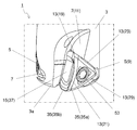
- FIG. 1 shows a milling tool 1 as an example of a cutting tool. However, the cutting tool is not limited to the milling tool 1.
- the rotary tool 1 (milling tool 1) of the non-limiting embodiment of the present disclosure may include a holder 3 and an insert 5 (cutting insert 5).
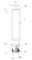
- the holder 3 may have a columnar shape extending from the first end 3a to the second end 3b along the rotation axis O1.
- the first end 3a may be restated as the leading end, and the second end 3b may be restated as the rear end.
- the rotary tool 1 can rotate around a rotation axis O1.
- the arrow X in FIG. 1 and the like indicates the rotation direction of the rotary tool 1.
- the material of the holder 3 may include steel and cast iron. In particular, from the viewpoint of enhancing the toughness of the holder 3, steel may be used among these materials.
- the holder 3 may have one or more pockets 7 located at the first end 3a.
- the number of pockets 7 is not particularly limited, and may be only one or plural.
- the holder 3 in the non-limiting example shown in FIG. 3 has three pockets 7.
- the holder 3 need not have a strict cylindrical shape, as will be clear from the fact that it can have pockets 7 and the like.
- the holder 3 may have a plurality of pockets 7, and the insert 5 may be located in each of these pockets 7.
- Each insert 5 may be located on the side of the first end 3 a of the rotary tool 1, as in a non-limiting example shown in FIG. 3.
- the pocket 7 is a portion to which the insert 5 is attached, and may be opened to the end surface located at the first end 3 a of the holder 3 and the outer peripheral surface 13.
- the rotary tool 1 may have three inserts 5, as the holder 3 has three pockets 7.
- the insert 5 may be in direct contact with the pocket 7, or a sheet may be sandwiched between the insert 5 and the pocket 7.
- the insert 5 may be brazed to the holder 3 or may be removable.
- these inserts 5 may have the same shape or different shapes.
- the pockets 7 may have the same shape or different shapes.
- a material having a hardness higher than that of the holder 3 is generally used.
- cemented carbide and cermet can be used as the material of the insert 5.
- the composition of the cemented carbide may include, for example, WC-Co, WC-TiC-Co and WC-TiC-TaC-Co.
- WC, TiC, and TaC are hard particles
- Co is a binder phase.
- cermet is a sintered composite material in which a metal is combined with a ceramic component.
- a titanium compound containing titanium carbide (TiC) or titanium nitride (TiN) as a main component may be mentioned.
- TiC titanium carbide
- TiN titanium nitride
- the material of the first insert 91 is not limited to the above composition.
- the surface of the insert 5 may be coated with a film using a chemical vapor deposition (CVD) method or a physical vapor deposition (PVD) method.
- the coating composition may include titanium carbide (TiC), titanium nitride (TiN), titanium carbonitride (TiCN), alumina (Al 2 O 3 ), and the like.
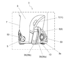
- first insert 9 One of the inserts 5 included in the rotary tool 1 is referred to as a first insert 9. Further, among the plurality of pockets 7, the pocket 7 in which the first insert 9 is located is referred to as a first pocket 11.
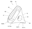
- the first insert 9 in the non-limiting embodiment of the present disclosure may have an outer peripheral surface 13, a first surface 15 and a second surface 17.
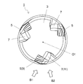
- the outer peripheral surface 13 may have a polygonal shape having a plurality of corners and a plurality of sides, as shown in FIG. 10.
- the outer peripheral surface 13 in the non-limiting example shown in FIG. 10 may be a substantially triangular shape having three corners and three sides.
- the three corners and the three sides of the outer peripheral surface 13 may be positioned so as to have a rotational symmetry of 120° with respect to the center of the outer peripheral surface 13 when the outer peripheral surface 13 is viewed from the front.
- the polygonal shape is not limited to a strictly polygonal shape.
- the three sides of the first surface 15 do not have to be strict straight lines.
- the center of the outer peripheral surface 13 can be specified by, for example, the position of the center of gravity of the outer peripheral surface 13 in front view.
- the outer peripheral surface 13 in the non-limiting example shown in FIG. 10 may have a first corner 19, a first side 21, and a second side 23.
- the first side 21 and the second side 23 may each extend from the first corner 19.
- the first corner 19 may be located between the first side 21 and the second side 23.
- the second side 23 may be located behind the first side 21 in the rotation direction X of the rotation axis O1.
- the first surface 15 and the second surface 17 may be adjacent to the outer peripheral surface 13, respectively.
- the first surface 15 may be connected to the first side 21.
- the second surface 17 may be connected to the second side 23. When the first side 21 and the second side 23 extend from the first corner 19, respectively, the first surface 15 and the second surface 17 may intersect with each other.
- the outer peripheral surface 13 may further include a second corner 25, a third corner 27, and a third side 29, as in a non-limiting example shown in FIG. 10.
- the third side 29 may be connected to the first side 21 on the side opposite to the second side 23.
- the third corner 27 may be located between the first side 21 and the third side 29.
- the third side 29 may be connected to the second side 23 on the side opposite to the first side 21 when the outer peripheral surface 13 has a substantially triangular shape as in a non-limiting example shown in FIG. 10.
- the second corner 25 may be located between the second side 23 and the third side 29.
- the first insert 9 may further have a third surface 31 connected to the third side 29.
- the third surface 31 may intersect with each of the first surface 15 and the second surface 17.
- the first insert 9 may further have an inner peripheral surface 33 located on the opposite side of the outer peripheral surface 13.
- the inner peripheral surface 33 may be parallel to the outer peripheral surface 13.
- the inner peripheral surface 33 may have a polygonal shape having a plurality of corners and a plurality of sides similarly to the outer peripheral surface 13.
- the inner peripheral surface 33 may have the same shape as the outer peripheral surface 13.
- the first insert 9 may have a polygonal plate shape.
- the first surface 15, the second surface 17, and the third surface 31 in the non-limiting example shown in FIGS. 10 and 11 may be located between the outer peripheral surface 13 and the inner peripheral surface 33, respectively. Further, the inner peripheral surface 33 may contact the first pocket 11.
- outer peripheral surface 13 and the inner peripheral surface 33 are not limited to the above shapes. In the non-limiting example shown in FIGS. 10 and 11, the outer peripheral surface 13 and the inner peripheral surface 33 are substantially triangular. However, the outer peripheral surface 13 and the inner peripheral surface 33 may be, for example, quadrangular, pentagonal, hexagonal, or octagonal, respectively.
- the maximum width when the outer peripheral surface 13 is viewed from the front may be, for example, 6 mm or more and 25 mm or less.
- the height from the outer peripheral surface 13 to the inner peripheral surface 33 may be, for example, 1 mm or more and 10 mm or less.
- the height from the outer peripheral surface 13 to the inner peripheral surface 33 may mean the maximum value of the interval in the direction parallel to the central axis passing through the center of the outer peripheral surface 13 and the center of the inner peripheral surface 33.
- the first insert 9 in the non-limiting embodiment of the present disclosure may have a cutting edge 35.
- the cutting edge 35 may have a role of cutting the work material at the time of cutting the work material for manufacturing a cut product.
- the cutting edge 35 in the non-limiting example illustrated in FIG. 10 may include a first cutting edge 35a.
- the first cutting edge 35a may be located on the first side 21.
- the first cutting edge 35a does not have to be located on the entire first side 21, and may be only a part of the first side 21.
- At least a part of the first cutting edge 35a may be located farther from the rotation axis O1 than the outer circumference of the holder 3. In other words, at least a part of the first cutting edge 35a may be located outside the outer circumference of the holder 3.
- the cutting edge 35 may further have a second cutting edge 35b as shown in FIG.
- the non-limiting example second cutting edge 35b illustrated in FIG. 10 may be located at the intersection of the first surface 15 and the third surface 31.
- the second cutting edge 35b does not have to be located at the entire intersection, and may be only a part of the intersection.
- At least a part of the second cutting edge 35b may be located farther from the second end 3b than the end surface of the holder 3 located at the first end 3a. In other words, at least a part of the second cutting edge 35b may protrude from the holder 3.
- the first cutting edge 35a can function as a so-called outer peripheral cutting edge.
- the second cutting edge 35b can function as a so-called bottom blade.
- the first surface 15 may have a rake face area 37 including an area along the first cutting edge 35a and the second cutting edge 35b.
- the rake face area 37 can function as a rake face with which chips come into contact when cutting is performed using the first cutting edge 35a and the second cutting edge 35b.
- the rake face region 37 may be the entire first face 15, or may be only a part of the first face 15 including the region along the first cutting edge 35a and the second cutting edge 35b. ..
- the outer peripheral surface 13 may have a first flank surface area 39 including an area along the first cutting edge 35a. Further, the third surface 31 may have a second flank surface area 41 including an area along the second cutting edge 35b.
- the first flank surface region 39 and the second flank surface region 41 can function as flank surfaces when performing cutting using the first cutting edge 35a and the second cutting edge 35b.
- the first flank surface region 39 may be the entire outer peripheral surface 13, and the second flank surface region 41 may be the entire third surface 31.
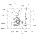
- the second surface 17 When the second side 23 is located behind the first side 21 in the rotation direction X, the second surface 17 may be located behind the first surface 15 in the rotation direction X. The second surface 17 may abut the pocket 7. When the second surface 17 comes into contact with the pocket 7, the main component force generated when the cutting process is performed using the first cutting edge 35 a is mainly transferred from the first insert 9 to the holder 3 on the second surface 17. Easy to communicate.
- the second surface 17 may have a flat portion 17a.
- the flat portion 17a can function as a surface that contacts the pocket 7.
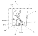
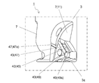
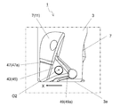
- the pocket 7 may have a concave portion 43 that is recessed when viewed from the side.
- the recess 43 may be located at a position facing the second surface 17. Specifically, the recess 43 may face the flat portion 17a.
- the recess 43 in the non-limiting embodiment of the present disclosure may have a bottom 45, a first region 47 and a second region 49.
- the first region 47 may be located in front of the bottom portion 45 in the rotation direction X and may be inclined with respect to the flat portion 17a when viewed from the side. Therefore, the first region 47 may approach the second surface 17 as it moves away from the bottom portion 45.
- the second region 49 may be located rearward of the bottom portion 45 in the rotation direction X and may be inclined with respect to the flat portion 17a when viewed from the side. Therefore, the second region 49 may approach the second surface 17 as it moves away from the bottom portion 45.
- the recess 43 in the non-limiting embodiment of the present disclosure may abut the first insert 9.
- the first region 47 and the second region 49 may abut the first insert 9.
- the first region 47 may have the first portion 47a that abuts the flat portion 17a.
- the second region 49 may have a second portion 49a that abuts the flat portion 17a.
- the bottom portion 45 may be separated from the first insert 9 while the first region 47 and the second region 49 contact the first insert 9.
- the first portion 47a and the second portion 49a are located apart from each other with the bottom portion 45 interposed therebetween, and the bottom portion 45 is separated from the first insert 9. Therefore, the first portion 47a and the second portion 49a are likely to stably come into contact with the first insert 9. As a result, the first insert 9 is likely to be stably held by the holder 3.
- the first region 47 and the second region 49 may approach the second surface 17 as they move away from the bottom 45. Therefore, the first region 47 may be inclined with respect to the second region 49.
- the angle ⁇ 0 at which the first imaginary line L1 extending the first region 47 and the second imaginary line L2 extending the second region 49 intersect may be an obtuse angle.
- the above main component force is mainly transmitted from the second surface 17 to the first region 47 and the second region 49.
- the angle ⁇ 0 is an obtuse angle, it is difficult for the load to concentrate on the bottom portion 45 located between the first region 47 and the second region 49. Therefore, the recess 43 is less likely to be cracked. Therefore, the durability of the holder 3 is high.
- the angle ⁇ 0 can be set to, for example, 160° to 179.95°.
- the first insert 9 may further have a through hole 51 that opens in the outer peripheral surface 13, as shown in FIG. 10.
- the through hole 51 in the non-limiting example shown in FIGS. 10 and 11 may be formed from the center of the outer peripheral surface 13 toward the center of the inner peripheral surface 33. At this time, the through hole 51 may be opened in the inner peripheral surface 33. Further, when the through hole 51 in the non-limiting example shown in FIGS. 10 and 11 is formed from the center of the outer peripheral surface 13 toward the center of the inner peripheral surface 33, as in the non-limiting example shown in FIG.
- the central axis O2 of the hole 51 may coincide with the central axis of the first insert 9.
- the through hole 51 can be used for inserting, for example, a screw 53 when fixing the first insert 9 to the holder 3.
- the screw 53 is inserted into the through hole 51 of the first insert 9, the tip of the screw 53 is inserted into the screw hole formed in the pocket 7, and the screw 53 is fixed to the screw hole. It may be attached to the holder 3.
- the through hole 51 in the non-limiting example shown in FIGS. 10 and 11 is formed from the center of the outer peripheral surface 13 toward the center of the inner peripheral surface 33, but the through hole 51 is not limited to such a configuration.
- the first insert 9 When the first insert 9 has the through hole 51, at least a part of the first portion 47a may be located forward of the central axis O2 of the through hole 51 in the rotation direction X.
- the main component force is hard to be applied to the screw 53. In other words, it is easy to stably and stably receive the above main component force at the first portion 47a. Therefore, the durability of the screw 53 is high.
- At least a part of the second portion 49a may be located closer to the first end 3a side than the central axis O2 of the through hole 51.
- the second portion 49a when the second portion 49a is positioned as described above, it is easy to stably and stably receive the main component force described above at the second portion 49a. Therefore, the main component force is hard to be applied to the screw 53, and the durability of the screw 53 is high.
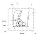
- the first area 47 and the second area 49 may be flat, in other words, flat.
- the first area 47 and the second area 49 may be curved surfaces.
- the first area 47 and the second area 49 may be convex curved surfaces as shown in FIG. 12, or may be concave as shown in FIG. It may be a curved surface.
- the first region 47 and the second region 49 may have a configuration in which a flat surface portion, a convex curved surface portion and a concave curved surface portion are combined.
- the first region 47 and the second region 49 may have a configuration in which convex curved surface portions and concave curved surface portions are combined.
- FIG. 12 is an enlarged view showing one holder 3 of a non-limiting embodiment of the present disclosure, and is a drawing corresponding to FIG. 9.
- FIG. 13 is an enlarged view showing one holder 3 of a non-limiting embodiment of the present disclosure, and is a drawing corresponding to FIG. 9.
- FIG. 14 is an enlarged view showing one holder 3 according to a non-limiting embodiment of the present disclosure, and is a drawing corresponding to FIG. 9.
- the durability of the first region 47 is high.
- the main component force is hard to concentrate on a part of the second region 49. Therefore, the durability of the second region 49 is high.
- the first region 47 has a convex curved surface shape
- the second region 49 has a convex curved surface shape
- the first region 47 has a convex curved surface shape
- the second region 49 has a convex curved surface shape, even if the pocket 7 is slightly deformed, it is easy to stably receive the main component force at the second portion 49a. Therefore, the durability of the second portion 49a is high.
- the non-limiting example outer peripheral surface 13 shown in FIG. 2 may have the first corner 19 and the second corner 25 adjacent to the second side 23, as described above. When viewed from the side, the first corner 19 and the second corner 25 may be separated from the recess 43, respectively.
- the first portion 47a When the first corner 19 is separated from the recess 43, the first portion 47a may be located apart from the first corner 19. At this time, chipping is less likely to occur in the vicinity of the first corner 19 when the main component force is received by the first portion 47a.
- the second portion 49 a when the second corner 25 is separated from the recess 43, the second portion 49 a may be located apart from the second corner 25. At this time, when the main component force is received by the second portion 49a, chipping is unlikely to occur near the second corner 25.
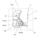
- the inclination angle of the first region 47 with respect to the flat portion 17a is the first angle ⁇ 1.
- the inclination angle of the second region 49 with respect to the flat portion 17a is a second angle ⁇ 2 when viewed from the side.
- the second angle ⁇ 2 may be larger than the first angle ⁇ 1.
- a large angle ⁇ 0 at which the first imaginary line L1 and the second imaginary line L2 intersect is ensured, and the main component force is stabilized in the second portion 49a. Easy to catch.
- the above configuration is effective when a relatively large cutting load is applied to a portion of the first cutting edge 35a near the first end 3a of the holder 3.
- FIG. 15 is an enlarged view showing one holder 3 of the non-limiting embodiment of the present disclosure, and is a drawing corresponding to FIG. 8.
- the first angle ⁇ 1 may be the same as the second angle ⁇ 2.
- the first angle ⁇ 1 is the same as the second angle ⁇ 2, it is easy to stably receive the main component force in each of the first portion 47a and the second portion 49a.
- the above configuration is effective when a large cutting load is likely to be applied not only to the portion of the first cutting edge 35a close to the first end 3a of the holder 3 but also to the portion away from the first end 3a.
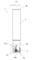
- FIGS. 16 to 18 show a method for manufacturing a machined product when the rotary tool 1 is used for machining. 16 to 18, the rotary shaft of the rotary tool 1 is shown by a chain double-dashed line.
- the cutting work 203 can be produced by cutting the work material 201.
- the method for manufacturing a cut product may include the following steps.
- the rotary tool 1 may be brought relatively close to the work material 201 while rotating in the X direction around the rotation axis O1.
- the cutting blade of the rotary tool 1 may be brought into contact with the work material 201 to cut the work material 201.
- the rotary tool 1 may be relatively separated from the work material 201.
- the work material 201 may be fixed and the rotary tool 1 may be brought closer. 16 to 18, the work material 201 may be fixed and the rotary tool 1 may be rotated around the rotation axis O1. 18, the work material 201 may be fixed and the rotary tool 1 may be moved away. In the above-described cutting process, the work material 201 is fixed and the rotary tool 1 is moved in each step, but of course the invention is not limited to such a form.
- the work material 201 may be brought close to the rotary tool 1.
- the work material 201 may be moved away from the rotary tool 1.
- the step of keeping the rotating tool 1 rotated and bringing the cutting edge of the insert into contact with different parts of the work material 201 may be repeated.
Landscapes
- Engineering & Computer Science (AREA)
- Mechanical Engineering (AREA)
- Milling Processes (AREA)
Priority Applications (1)
| Application Number | Priority Date | Filing Date | Title |
|---|---|---|---|
| JP2020563305A JP7223773B2 (ja) | 2018-12-25 | 2019-12-24 | 回転工具及び切削加工物の製造方法 |
Applications Claiming Priority (2)
| Application Number | Priority Date | Filing Date | Title |
|---|---|---|---|
| JP2018-241817 | 2018-12-25 | ||
| JP2018241817 | 2018-12-25 |
Publications (1)
| Publication Number | Publication Date |
|---|---|
| WO2020138084A1 true WO2020138084A1 (ja) | 2020-07-02 |
Family
ID=71129395
Family Applications (1)
| Application Number | Title | Priority Date | Filing Date |
|---|---|---|---|
| PCT/JP2019/050610 Ceased WO2020138084A1 (ja) | 2018-12-25 | 2019-12-24 | 回転工具及び切削加工物の製造方法 |
Country Status (2)
| Country | Link |
|---|---|
| JP (1) | JP7223773B2 (enExample) |
| WO (1) | WO2020138084A1 (enExample) |
Citations (3)
| Publication number | Priority date | Publication date | Assignee | Title |
|---|---|---|---|---|
| JPS49100285U (enExample) * | 1972-12-20 | 1974-08-29 | ||
| JPS6288508A (ja) * | 1985-10-11 | 1987-04-23 | Toshiba Corp | 正面フライスカツタ |
| JP2018534157A (ja) * | 2015-11-19 | 2018-11-22 | イスカル リミテッド | 三角形の接線方向のフライス用インサート及びフライス工具 |
-
2019
- 2019-12-24 JP JP2020563305A patent/JP7223773B2/ja active Active
- 2019-12-24 WO PCT/JP2019/050610 patent/WO2020138084A1/ja not_active Ceased
Patent Citations (3)
| Publication number | Priority date | Publication date | Assignee | Title |
|---|---|---|---|---|
| JPS49100285U (enExample) * | 1972-12-20 | 1974-08-29 | ||
| JPS6288508A (ja) * | 1985-10-11 | 1987-04-23 | Toshiba Corp | 正面フライスカツタ |
| JP2018534157A (ja) * | 2015-11-19 | 2018-11-22 | イスカル リミテッド | 三角形の接線方向のフライス用インサート及びフライス工具 |
Also Published As
| Publication number | Publication date |
|---|---|
| JPWO2020138084A1 (enExample) | 2020-07-02 |
| JP7223773B2 (ja) | 2023-02-16 |
Similar Documents
| Publication | Publication Date | Title |
|---|---|---|
| JP7417713B2 (ja) | 切削インサート、切削工具及び切削加工物の製造方法 | |
| CN108698143B (zh) | 切削工具用刀具 | |
| JP6467049B2 (ja) | 切削工具及び切削加工物の製造方法 | |
| JP7128185B2 (ja) | 切削インサート、切削工具及び切削加工物の製造方法 | |
| JP6810807B2 (ja) | 切削インサート、切削工具及び切削加工物の製造方法 | |
| JP7114733B2 (ja) | 切削インサート、切削工具及び切削加工物の製造方法 | |
| JPWO2018221362A1 (ja) | エンドミル及び切削加工物の製造方法 | |
| JP7223773B2 (ja) | 回転工具及び切削加工物の製造方法 | |
| JP7045460B2 (ja) | 切削工具及び切削加工物の製造方法 | |
| JP7281532B2 (ja) | 旋削工具及び切削加工物の製造方法 | |
| JP2020069598A (ja) | 切削インサート、切削工具、及び切削加工物の製造方法 | |
| WO2019022016A1 (ja) | 切削インサート、切削工具及び切削加工物の製造方法 | |
| JP7257230B2 (ja) | 切削インサート、切削工具、及び切削加工物の製造方法 | |
| JP6825854B2 (ja) | 切削工具及び切削加工物の製造方法 | |
| JP7770537B2 (ja) | 回転工具及び切削加工物の製造方法 | |
| JP7758646B2 (ja) | 切削工具及び切削加工物の製造方法 | |
| JP7645174B2 (ja) | 切削工具及び切削加工物の製造方法 | |
| CN112888520B (zh) | 切削刀片、切削刀具以及切削加工物的制造方法 | |
| JP7117389B2 (ja) | 切削インサート、切削工具及び切削加工物の製造方法 | |
| WO2024224816A1 (ja) | 切削インサート、切削工具及び切削加工物の製造方法 | |
| JP7239480B2 (ja) | 切削インサート、切削工具及び切削加工物の製造方法 | |
| JP6892369B2 (ja) | 切削インサート、切削工具及び切削加工物の製造方法 | |
| WO2025216120A1 (ja) | 切削インサート、切削工具及び切削加工物の製造方法 | |
| WO2023176618A1 (ja) | 切削インサート、切削工具、及び切削加工物の製造方法 |
Legal Events
| Date | Code | Title | Description |
|---|---|---|---|
| 121 | Ep: the epo has been informed by wipo that ep was designated in this application |
Ref document number: 19902501 Country of ref document: EP Kind code of ref document: A1 |
|
| NENP | Non-entry into the national phase |
Ref country code: DE |
|
| ENP | Entry into the national phase |
Ref document number: 2020563305 Country of ref document: JP Kind code of ref document: A |
|
| 122 | Ep: pct application non-entry in european phase |
Ref document number: 19902501 Country of ref document: EP Kind code of ref document: A1 |