WO2020137899A1 - カテーテル組立体 - Google Patents
カテーテル組立体 Download PDFInfo
- Publication number
- WO2020137899A1 WO2020137899A1 PCT/JP2019/050132 JP2019050132W WO2020137899A1 WO 2020137899 A1 WO2020137899 A1 WO 2020137899A1 JP 2019050132 W JP2019050132 W JP 2019050132W WO 2020137899 A1 WO2020137899 A1 WO 2020137899A1
- Authority
- WO
- WIPO (PCT)
- Prior art keywords
- catheter
- tube
- stylet
- blood
- hub
- Prior art date
- Legal status (The legal status is an assumption and is not a legal conclusion. Google has not performed a legal analysis and makes no representation as to the accuracy of the status listed.)
- Ceased
Links
Images







Classifications
-
- A—HUMAN NECESSITIES
- A61—MEDICAL OR VETERINARY SCIENCE; HYGIENE
- A61M—DEVICES FOR INTRODUCING MEDIA INTO, OR ONTO, THE BODY; DEVICES FOR TRANSDUCING BODY MEDIA OR FOR TAKING MEDIA FROM THE BODY; DEVICES FOR PRODUCING OR ENDING SLEEP OR STUPOR
- A61M25/00—Catheters; Hollow probes
- A61M25/01—Introducing, guiding, advancing, emplacing or holding catheters
- A61M25/0102—Insertion or introduction using an inner stiffening member, e.g. stylet or push-rod
-
- A—HUMAN NECESSITIES
- A61—MEDICAL OR VETERINARY SCIENCE; HYGIENE
- A61M—DEVICES FOR INTRODUCING MEDIA INTO, OR ONTO, THE BODY; DEVICES FOR TRANSDUCING BODY MEDIA OR FOR TAKING MEDIA FROM THE BODY; DEVICES FOR PRODUCING OR ENDING SLEEP OR STUPOR
- A61M1/00—Suction or pumping devices for medical purposes; Devices for carrying-off, for treatment of, or for carrying-over, body-liquids; Drainage systems
- A61M1/36—Other treatment of blood in a by-pass of the natural circulatory system, e.g. temperature adaptation, irradiation ; Extra-corporeal blood circuits
- A61M1/3621—Extra-corporeal blood circuits
- A61M1/3653—Interfaces between patient blood circulation and extra-corporal blood circuit
- A61M1/3659—Cannulae pertaining to extracorporeal circulation
-
- A—HUMAN NECESSITIES
- A61—MEDICAL OR VETERINARY SCIENCE; HYGIENE
- A61M—DEVICES FOR INTRODUCING MEDIA INTO, OR ONTO, THE BODY; DEVICES FOR TRANSDUCING BODY MEDIA OR FOR TAKING MEDIA FROM THE BODY; DEVICES FOR PRODUCING OR ENDING SLEEP OR STUPOR
- A61M1/00—Suction or pumping devices for medical purposes; Devices for carrying-off, for treatment of, or for carrying-over, body-liquids; Drainage systems
- A61M1/36—Other treatment of blood in a by-pass of the natural circulatory system, e.g. temperature adaptation, irradiation ; Extra-corporeal blood circuits
- A61M1/3621—Extra-corporeal blood circuits
- A61M1/3666—Cardiac or cardiopulmonary bypass, e.g. heart-lung machines
-
- A—HUMAN NECESSITIES
- A61—MEDICAL OR VETERINARY SCIENCE; HYGIENE
- A61M—DEVICES FOR INTRODUCING MEDIA INTO, OR ONTO, THE BODY; DEVICES FOR TRANSDUCING BODY MEDIA OR FOR TAKING MEDIA FROM THE BODY; DEVICES FOR PRODUCING OR ENDING SLEEP OR STUPOR
- A61M25/00—Catheters; Hollow probes
- A61M25/0097—Catheters; Hollow probes characterised by the hub
-
- A—HUMAN NECESSITIES
- A61—MEDICAL OR VETERINARY SCIENCE; HYGIENE
- A61M—DEVICES FOR INTRODUCING MEDIA INTO, OR ONTO, THE BODY; DEVICES FOR TRANSDUCING BODY MEDIA OR FOR TAKING MEDIA FROM THE BODY; DEVICES FOR PRODUCING OR ENDING SLEEP OR STUPOR
- A61M39/00—Tubes, tube connectors, tube couplings, valves, access sites or the like, specially adapted for medical use
- A61M39/10—Tube connectors; Tube couplings
-
- A—HUMAN NECESSITIES
- A61—MEDICAL OR VETERINARY SCIENCE; HYGIENE
- A61M—DEVICES FOR INTRODUCING MEDIA INTO, OR ONTO, THE BODY; DEVICES FOR TRANSDUCING BODY MEDIA OR FOR TAKING MEDIA FROM THE BODY; DEVICES FOR PRODUCING OR ENDING SLEEP OR STUPOR
- A61M60/00—Blood pumps; Devices for mechanical circulatory actuation; Balloon pumps for circulatory assistance
- A61M60/10—Location thereof with respect to the patient's body
- A61M60/104—Extracorporeal pumps, i.e. the blood being pumped outside the patient's body
- A61M60/109—Extracorporeal pumps, i.e. the blood being pumped outside the patient's body incorporated within extracorporeal blood circuits or systems
-
- A—HUMAN NECESSITIES
- A61—MEDICAL OR VETERINARY SCIENCE; HYGIENE
- A61M—DEVICES FOR INTRODUCING MEDIA INTO, OR ONTO, THE BODY; DEVICES FOR TRANSDUCING BODY MEDIA OR FOR TAKING MEDIA FROM THE BODY; DEVICES FOR PRODUCING OR ENDING SLEEP OR STUPOR
- A61M60/00—Blood pumps; Devices for mechanical circulatory actuation; Balloon pumps for circulatory assistance
- A61M60/20—Type thereof
- A61M60/205—Non-positive displacement blood pumps
- A61M60/216—Non-positive displacement blood pumps including a rotating member acting on the blood, e.g. impeller
- A61M60/226—Non-positive displacement blood pumps including a rotating member acting on the blood, e.g. impeller the blood flow through the rotating member having mainly radial components
- A61M60/232—Centrifugal pumps
-
- A—HUMAN NECESSITIES
- A61—MEDICAL OR VETERINARY SCIENCE; HYGIENE
- A61M—DEVICES FOR INTRODUCING MEDIA INTO, OR ONTO, THE BODY; DEVICES FOR TRANSDUCING BODY MEDIA OR FOR TAKING MEDIA FROM THE BODY; DEVICES FOR PRODUCING OR ENDING SLEEP OR STUPOR
- A61M60/00—Blood pumps; Devices for mechanical circulatory actuation; Balloon pumps for circulatory assistance
- A61M60/30—Medical purposes thereof other than the enhancement of the cardiac output
- A61M60/36—Medical purposes thereof other than the enhancement of the cardiac output for specific blood treatment; for specific therapy
- A61M60/38—Blood oxygenation
-
- A—HUMAN NECESSITIES
- A61—MEDICAL OR VETERINARY SCIENCE; HYGIENE
- A61M—DEVICES FOR INTRODUCING MEDIA INTO, OR ONTO, THE BODY; DEVICES FOR TRANSDUCING BODY MEDIA OR FOR TAKING MEDIA FROM THE BODY; DEVICES FOR PRODUCING OR ENDING SLEEP OR STUPOR
- A61M25/00—Catheters; Hollow probes
- A61M2025/0004—Catheters; Hollow probes having two or more concentrically arranged tubes for forming a concentric catheter system
- A61M2025/0006—Catheters; Hollow probes having two or more concentrically arranged tubes for forming a concentric catheter system which can be secured against axial movement, e.g. by using a locking cuff
-
- A—HUMAN NECESSITIES
- A61—MEDICAL OR VETERINARY SCIENCE; HYGIENE
- A61M—DEVICES FOR INTRODUCING MEDIA INTO, OR ONTO, THE BODY; DEVICES FOR TRANSDUCING BODY MEDIA OR FOR TAKING MEDIA FROM THE BODY; DEVICES FOR PRODUCING OR ENDING SLEEP OR STUPOR
- A61M25/00—Catheters; Hollow probes
- A61M25/0021—Catheters; Hollow probes characterised by the form of the tubing
- A61M25/0023—Catheters; Hollow probes characterised by the form of the tubing by the form of the lumen, e.g. cross-section, variable diameter
- A61M2025/0024—Expandable catheters or sheaths
Definitions
- the present invention relates to a catheter assembly including a blood supply hole that supplies blood to a living body.
- PCPS percutaneous cardiopulmonary support
- the extracorporeal circulation device is equipped with an extracorporeal circulation circuit composed of a centrifugal pump, an artificial lung, a blood removal path, a blood supply path, and the like, and exchanges gas with respect to the blood that has been removed, and supplies the blood to the blood supply path.
- Patent Document 1 describes a circulation circuit of an extracorporeal circulation device.
- a catheter having a blood supply hole is used to send blood after gas exchange to a desired position of the living body.
- the catheter is used by being placed at a predetermined position in the living body for performing extracorporeal circulation.
- a catheter that can be expanded and contracted in the radial direction and the axial direction (longitudinal direction) is used in order to facilitate placement at a predetermined position, and the shape of the catheter during movement of the living body lumen is regulated.
- a medical device such as a stylet may be used together.
- the stylet has a function of contracting in the radial direction by applying tension in the axial direction of the catheter to extend it when the catheter is inserted into a living body lumen.
- the catheter and stylet may be secured by engaging a helical shape such as a screw.
- the present invention provides a catheter assembly that prevents or suppresses the deterioration of the insertability of the catheter during percutaneous insertion by preventing or suppressing the twist that occurs in the catheter when connecting the catheter and the stylet.
- the purpose is to provide.
- a catheter assembly that achieves the above-mentioned object is formed in an elongated shape, and has an expandable and contractible tube provided with a lumen through which blood can flow, and a distal end portion of the tube.
- a catheter having an extensible first contact portion, and a stylet configured to be insertable into the lumen and capable of extending the tube in the longitudinal direction by contact with the first contact portion.
- a connector that is provided on the proximal end side of the catheter and is connectable to the stylet; the connector includes a first engaging portion that is engageable with the stylet;
- a hub disposed on the proximal end side of the catheter; and a connecting member that connects the hub and the connector and that is rotatable independently of the hub to engage with the first engaging portion. ..
- the stylet is configured to include the connecting member that can be engaged with the first engaging portion by rotating independently of the hub.
- the connecting member of the stylet is rotated, the rotation is not or hardly transmitted to the hub of the stylet, so that the catheter can be prevented or suppressed from being twisted. Therefore, it is possible to prevent or suppress a decrease in the insertability of the catheter during percutaneous insertion.
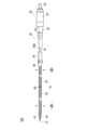
- FIG. 1 is a system diagram showing an example of an extracorporeal circulation device to which a percutaneous catheter provided in a catheter assembly according to an embodiment of the present invention is applied. It is a side view which shows the catheter assembly which concerns on 1st Embodiment separately in a percutaneous catheter and a stylet. It is a side sectional view showing the percutaneous catheter concerning a 1st embodiment. It is a side view which shows the catheter assembly in the state which inserted the stylet in the percutaneous catheter which concerns on 1st Embodiment. It is an expanded sectional view which shows the percutaneous catheter with which the stylet was inserted. It is a figure which shows a front-end
- FIG. 9 is a side cross-sectional view showing a straight connector and a stylet connected at the proximal end side of the catheter assembly according to Modification 1.
- FIG. 9 is a side cross-sectional view showing an example of a straight connector and a stylet configured on the proximal end side of the catheter assembly according to Modification 1.
- FIG. 10 is a partially enlarged view of FIG. 9.
- FIG. 11 is a side cross-sectional view showing another example of the straight connector and the stylet configured on the proximal end side of the catheter assembly according to the modified example 1.
- FIG. 12 is a partially enlarged view of FIG. 11.
- FIG. 11 is a side cross-sectional view showing a straight connector and a stylet connected at the proximal end side of a catheter assembly according to Modification 2. It is a top view which shows the catheter assembly which concerns on 2nd Embodiment isolate
- FIG. 1 is a diagram showing an example of an extracorporeal circulation device to which a catheter provided in a catheter assembly according to an embodiment of the present invention is applied.
- the extracorporeal circulation device can be used for, for example, percutaneous cardiopulmonary support (PCPS), which temporarily assists or substitutes the functions of the heart and lungs until the heart function is restored when the patient's heart is weak. ..
- PCPS percutaneous cardiopulmonary support
- the extracorporeal circulation device 1 can be used for a venous-arterial (Veno-Arterial, VA) procedure.
- the venous-arterial system (Veno-Arterial, VA) is a method in which a pump is operated to remove blood from a patient's vein (for example, the vena cava), and gas is exchanged in the blood by the artificial lung 2 to oxygenate blood. After conversion, this blood is returned to the patient's artery (eg, aorta).
- the extracorporeal circulation device 1 can be used as a device for assisting the heart and lungs of a patient.
- extracorporeal circulation a procedure of removing blood from a patient, performing a predetermined treatment outside the body, and then sending blood to the body of the patient again is referred to as “extracorporeal circulation”.
- the extracorporeal circulation device 1 has a circulation circuit for circulating blood.
- the circulation circuit includes an artificial lung 2, a centrifugal pump 3, a drive motor 4 that is a driving means for driving the centrifugal pump 3, a vein side catheter (percutaneous catheter for blood removal) 5, and a control unit.
- the controller 10 is included.
- the venous catheter (for blood removal) catheter 5 is inserted from the femoral vein, and the tip of the venous catheter 5 is placed in the right atrium via the inferior vena cava.
- the vein side catheter 5 is connected to the centrifugal pump 3 via a blood removal tube (blood removal line) 11.
- the blood removal tube 11 is a conduit for sending blood.
- the arterial catheter (blood supply catheter) 6 is inserted from the femoral artery.
- the drive motor 4 operates the centrifugal pump 3 based on the command SG from the controller 10.
- the centrifugal pump 3 passes the blood removed from the blood removal tube 11 through the artificial lung 2, and then returns the blood to the patient P via the blood supply tube (blood supply line) 12.
- the artificial lung 2 is arranged between the centrifugal pump 3 and the blood supply tube 12.
- the artificial lung 2 performs gas exchange (oxygen addition and/or carbon dioxide removal) for blood.
- a membrane oxygenator can be used, and particularly preferably, a hollow fiber membrane oxygenator can be used.
- Oxygen gas is supplied from the oxygen gas supply unit 13 to the artificial lung 2 through the tube 14.
- the blood supply tube 12 is a conduit connecting the artificial lung 2 and the arterial catheter 6.
- a conduit made of a synthetic resin such as vinyl chloride resin or silicone rubber, which has high transparency and is elastically deformable and flexible, can be used.
- a synthetic resin such as vinyl chloride resin or silicone rubber, which has high transparency and is elastically deformable and flexible
- the detection sensor 20 is arranged in the middle of the blood removal tube 11.
- a fast clamp 17 is arranged in the middle of the blood supply tube 12.
- the detection sensor 20 detects the mixed bubbles by ultrasonic waves when the bubbles are mixed in the circuit due to an erroneous operation of the three-way stopcock 18 or a tube breakage during extracorporeal circulation.
- the detection sensor 20 detects that there is an air bubble in the blood sent into the blood removal tube 11
- the detection sensor 20 sends a detection signal to the controller 10.
- the controller 10 issues an alarm warning and lowers the rotation speed of the centrifugal pump 3 or stops the centrifugal pump 3.
- the controller 10 instructs the fast clamp 17 to immediately close the blood supply tube 12 by the fast clamp 17. This prevents bubbles from being sent into the body of the patient P.
- the controller 10 controls the operation of the extracorporeal circulation device 1 to prevent air bubbles from entering the body of the patient P.
- a pressure sensor is provided on the tubes 11 (12, 19) of the circulation circuit of the extracorporeal circulation device 1.
- the pressure sensor is, for example, of the attachment position A1 of the blood removal tube 11, the attachment position A2 of the blood supply tube 12 of the circulation circuit, or the attachment position A3 of the connection tube 19 connecting between the centrifugal pump 3 and the artificial lung 2. Can be placed in at least one place.
- the pressure sensor measures the pressure inside each of the tubes 11, 12, and 19 while the extracorporeal circulation device 1 is performing extracorporeal circulation on the patient P.
- the mounting position of the pressure sensor is not limited to the mounting positions A1, A2, A3, and may be mounted at any position in the circulation circuit.
- the catheter assembly 100 according to this embodiment includes a catheter 30 and a stylet 50.
- the catheter 30 is used as the vein side catheter (blood removal catheter) 5 in FIG.
- the catheter 30 has a catheter tube 31 (corresponding to a “tube”) having a side hole 63, and a distal tip provided at the tip of the catheter tube 31 and having through holes 46 and 47. 41.
- the catheter 30 includes a clamp tube 34 arranged on the proximal end side of the catheter tube 31, a catheter connector 35 connecting the catheter tube 31 and the clamp tube 34, and a straight connector 36 (corresponding to a “connector”). Have.
- the side to be inserted into the living body is referred to as the “tip” or “tip side”, and the side operated by the operator is referred to as “base end” or “base end side”.
- the tip portion means a certain range including the tip (the most distal end) and its periphery
- the base end portion means a certain range including the base end (the most proximal end) and its periphery.
- the catheter 30 has a lumen 30A penetrating from the distal end to the proximal end as shown in FIG.
- the through holes 46 and 47 of the tip 41 and the side holes 63 of the catheter tube 31 are arranged for different blood removal targets in the living body so that blood removal can be performed efficiently.
- a stylet 50 is used when inserting the catheter 30 into the living body as shown in FIG.
- the stylet 50 is inserted through the lumen 30A of the catheter 30, and the catheter 30 and the stylet 50 are integrated in advance and inserted into the living body. Blood is allowed to flow in the lumen 30A. The method of using the catheter 30 will be described later.
- the catheter tube 31 is configured to be elongated and expandable.
- the catheter tube 31 has a first tube 32 and a second tube 33 arranged on the proximal end side of the first tube 32, as shown in FIG. 2.
- the first tube 32 is configured to have higher elasticity than the second tube 33.
- the first tube 32 has a larger outer diameter and inner diameter than the second tube 33.
- the first tube 32 and the second tube 33 are integrally formed and have a substantially constant wall thickness.
- the lengths of the first tube 32 and the second tube 33 are configured to be the lengths necessary for arranging the through holes 46, 47 and the side hole 63 of the distal tip 41 on a desired blood removal target.
- the length of the first tube 32 can be, for example, 20 to 40 cm
- the length of the second tube 33 can be, for example, 20 to 30 cm.
- the side hole 63 is a hole that penetrates the side surface of the second tube 33 and is opened so as to communicate with the lumen 30A of the catheter 30.
- the side hole 63 functions as a blood removal hole. It is preferable to provide a plurality of side holes 63 because blood can be removed from the other side holes even if any of the side holes 63 is adsorbed to the blood vessel wall and blocked, and stable extracorporeal circulation can be performed.
- blood removal targets are the right atrium and the inferior vena cava.
- the catheter 30 is inserted and left in the living body so that the through holes 46 and 47 of the tip 41 are arranged in the right atrium.
- the first tube 32 is placed in the inferior vena cava, which is a relatively thick blood vessel, and the second tube 33 is a femoral vein, which is a relatively thin blood vessel, with the through holes 46, 47 and the side holes 63 being placed in the blood removal target. Is located in.
- the highly stretchable first tube 32 extends in the axial direction and the outer diameter and inner diameter of the first tube 32 become smaller.
- the outer diameter and inner diameter of the first tube 32 are substantially the same as the outer diameter and inner diameter of the second tube 33. Since the catheter 30 is inserted into the living body in a state where the first tube 32 is extended in the axial direction and the outer diameter is reduced, the catheter 30 can be inserted minimally invasively.
- the first tube 32 contracts in the axial direction and the outer diameter and the inner diameter of the first tube 32 are reduced as shown in FIG. growing.
- the first tube 32 is arranged in the inferior vena cava, which is a relatively thick blood vessel, the outer diameter of the first tube 32 can be increased.
- the pressure loss when blood or the like flows through the first tube 32 can be reduced by increasing the inner diameter of the first tube 32.
- the pressure loss is reduced, the flow rate of blood flowing through the circulation circuit increases. Therefore, in order to obtain a sufficient blood circulation amount, it is necessary to make the inner diameter of the first tube 32 sufficiently large.
- the inner diameter of the first tube 32 may be, for example, 9 to 11 mm, and the inner diameter of the second tube 33 may be, for example, 4 to 8 mm.
- the wall thickness of the first tube 32 and the second tube 33 can be set to 0.3 to 0.5 mm, for example.
- the distal end portion and the proximal end portion of the first tube 32 are tapered portions that gradually become thinner from the center in the longitudinal direction of the first tube 32 toward the distal end portion and the proximal end portion. Are preferably formed. Thereby, the inner diameters of the distal end and the proximal end of the first tube 32 can easily be continuously connected to the inner diameter of the distal end tip 41 disposed on the distal end side and the inner diameter of the second tube 33 disposed on the proximal end side. it can.
- the catheter tube 31 includes a tubular reinforcing body 320 braided in a mesh shape so as to intersect the wires W, and a first resin layer 331 and a second resin layer provided so as to cover the reinforcing body 320. And a layer 332.
- the first tube 32 is composed of the distal end 320 a of the reinforcing body 320 and the first resin layer 331
- the second tube 33 is composed of the proximal end 320 b of the reinforcing body 320 and the second resin layer 332.
- Innumerable gaps or openings are formed in the reinforcing body 320 by braiding a plurality of wires W.
- the size relation of the plurality of gaps is not particularly limited.
- the second resin layer 332 is formed so as to cover the inner peripheral surface of the opening of the reinforcing body 320. This can prevent the wire from being exposed from the inner peripheral surface of the side hole 63.
- the maximum length of the opening can be set to about 2 or 3 mm.
- the wire W forming the reinforcing body 320 is made of a shape memory material such as a known shape memory metal or shape memory resin.
- a shape memory material such as a known shape memory metal or shape memory resin.
- shape memory metal for example, titanium-based (Ti-Ti, Ti-Pd, Ti-Nb-Sn, etc.) or copper-based alloy can be used.
- shape memory resin for example, acrylic resin, transisoprene polymer, polynorbornene, styrene-butadiene copolymer, polyurethane can be used.
- the cross-sectional shape of the wire W forming the reinforcing body 320 is rectangular in the present embodiment. However, the shape is not limited to this, and may be a square, a circle, an ellipse, or the like other than the above. When the cross-sectional shape is circular, the wire diameter of the wire W may be, for example, 0.1 mm to 0.2 mm.
- the first resin layer 331 forming the first tube 32 is made of a material softer than the second resin layer 332 forming the second tube 33. With this configuration, the first tube 32 can be made softer than the second tube 33, and the elasticity can be enhanced.
- the material forming the first resin layer 33 a known resin that is relatively soft can be used.
- urethane, polyurethane, silicon, or vinyl chloride having a low hardness can be used.
- the material forming the second resin layer 332 for example, urethane, polyurethane, silicon, or vinyl chloride having high hardness can be used.
- hydrophilic coating may be applied to the surface. This increases the lubricity of the surface of the catheter tube 31, facilitates insertion into the living body, improves operability, and prevents damage to the blood vessel wall. In addition, blood and proteins are less likely to adhere, and it can be expected to prevent the formation of thrombus.
- the tip 41 is fixed to the tip of the first tube 32. As shown in FIG. 6, the tip 41 has a tapered shape whose diameter is gradually reduced toward the tip side. As shown in FIG. 6, the distal tip 41 has a base portion 49 that is inserted into the distal end of the first tube 32, a plurality of through holes 46 provided in the side surface, and a through hole 47 provided at the distal end of the distal tip 41. Have. The through holes 46 and 47 function as blood removal holes. The through hole 47 of the tip 41 is configured to communicate with the lumen 30A of the catheter 30.
- the tip 41 can be formed of, for example, hard plastic or the like.
- first abutting portion that abuts a flat surface 50a of a stylet 50 used prior to insertion of the catheter 30 into a living body. "Corresponding to”) is formed. As will be described later, the tip of the stylet 50 abuts the receiving surface 48, whereby the catheter 30 extends in the longitudinal direction.
- the clamp tube 34 is provided on the base end side of the second tube 33.
- a lumen through which the stylet 50 can be inserted is provided inside the clamp tube 34.
- the clamp tube 34 can be formed using the same material as the catheter tube 31.
- the catheter connector 35 connects the second tube 33 and the clamp tube 34.
- a lumen through which the stylet 50 can be inserted is provided inside the catheter connector 35.
- the straight connector 36 is provided on the proximal end side of the catheter 30.
- the straight connector 36 is connected to the proximal end side of the clamp tube 34.
- the straight connector 36 has a circular cross section at the base end that intersects the longitudinal direction.
- a lumen through which the stylet 50 can be inserted is provided inside the straight connector 36.
- a male screw portion 36A (corresponding to a "first engaging portion") capable of engaging with the female screw portion 53C of the stylet 50 is provided on the outer circumference of the straight connector 36.
- the straight connector 36 is configured to be connectable to the stylet 50 by the male screw portion 36A.
- the stylet 50 includes a stylet tube 51 provided to extend in the axial direction as shown in FIG. 2, a stylet hub 52 (corresponding to a “hub”) to which a base end of the stylet tube 51 is fixed, have.
- the stylet 50 has a connecting member 53 that is provided on the tip side of the stylet hub 52 and connects the stylet hub 52 and the straight connector 36.
- the stylet tube 51 is an elongated body that extends in the axial direction and has relatively high rigidity.
- the stylet tube 51 is configured to be insertable into the lumen 30A of the catheter 30.
- the overall length of the stylet tube 51 along the axial direction is longer than the overall length of the catheter 30 along the axial direction.
- the stylet tube 51 includes a guide wire lumen 54 into which a guide wire (not shown) can be inserted (see FIG. 5).
- the stylet tube 51 is guided by the guide wire and inserted into the living body together with the catheter 30.
- the stylet tube 51 is removed from the catheter 30 by leaving the catheter 30 in the living body and then withdrawing the stylet hub 52 to the proximal end side.
- the tip of the stylet tube 51 is provided with a flat surface 50a that abuts the receiving surface 48 of the tip 41, as shown in FIG.
- the stylet tube 51 has relatively high rigidity and is provided with a stiffness that allows the pushing force to the distal end side by the operation at hand to be transmitted to the distal end tip 41. Therefore, in the stylet tube 51, the flat surface 50a is brought into contact with the receiving surface 48 of the distal end tip 41 and the distal end tip 41 is pushed toward the distal end side, whereby the catheter tube 31 is elongated in the longitudinal direction and a narrow blood vessel is formed. Plays a role of expansion.
- the stylet hub 52 is arranged on the proximal end side of the catheter 30 when the catheter 30 is connected to the stylet 50. As shown in FIG. 7, the stylet hub 52 includes an extending portion 52A that extends along the first surrounding portion 53B of the connecting member 53, which will be described later, in the outer circumferential direction of the stylet hub 52.
- the extending portion 52A is formed in a hollow circular shape in a cross section that intersects with the longitudinal direction.
- the connecting member 53 extends in the longitudinal direction so as to surround a mounting portion 53A attached to the stylet hub 52 and a female screw portion 53C (second engaging portion) described later.
- the first surrounding portion 53B is provided.
- the attachment portion 53A is rotatably attached to the stylet hub 52.
- the mounting portion 53A is arranged to be separated from the outer surface 52D of the stylet hub 52 in the radial direction or the radial direction.
- the mounting portion 53A applies a pressing force to the outer surface 52E of the stylet hub 52 by screwing a male screw portion 36A and a female screw portion 53C described later, and fixes the stylet hub 52 to the straight connector 36 in the longitudinal direction. Give power.
- the extending portion 52A extends along the first surrounding portion 53B and contacts the male screw portion 36A (engaging portion). By the surface contact between the male screw portion 36A and the extending portion 52A, a seal portion 55 that seals the proximal end side of the catheter 30 is configured between the catheter 30 and the stylet 50.
- the connecting member 53 includes a female screw portion 53C, which is engaged with the male screw portion 36A by screwing, on the front end side of the first surrounding portion 53B, and rotates independently of the stylet hub 52 to generate a male screw. It is engageable with the portion 36A.
- the female screw portion 53C is provided on the opposite side of the attachment portion 53A in the longitudinal direction.
- the female screw portion 53C is configured such that the connecting member 53 can be detachably attached to the straight connector 36 by screwing.
- the female screw portion 53C corresponds to the second engaging portion in this specification.
- FIG. 2 shows a state before inserting the stylet tube 51 of the stylet 50 into the lumen 30A of the catheter 30
- FIG. 4 shows a state after inserting the stylet tube 51 into the lumen 30A of the catheter 30.
- an operator such as a doctor inserts the stylet tube 51 of the stylet 50 into the lumen 30A of the catheter 30.
- the stylet tube 51 passes through the straight connector 36, the clamp tube 34, the catheter connector 35, the second tube 33, and the first tube 32 in order.
- the flat surface 50a of the stylet tube 51 contacts the receiving surface 48 of the tip 41 (see FIG. 5).
- the overall length of the stylet tube 51 in the axial direction is longer than the overall length of the catheter 30 in the axial direction. Therefore, the flat tip 50a of the stylet tube 51 is pressed toward the tip side of the tip tip 41 while being in contact with the receiving surface 48 of the tip tip 41. As a result, the tip of the first tube 32 fixed to the tip 41 is pulled toward the tip side.
- the catheter 30 receives a force in the extending direction, and the first tube 32 of the catheter 30, which has relatively high elasticity, extends in the axial direction.
- the outer diameter of the first tube 32 becomes smaller and becomes substantially the same as the outer diameter of the second tube 33.
- the proximal end of the catheter 30 and the stylet hub 52 are fixed with the first tube 32 extended in the axial direction.
- the proximal end of the catheter 30 and the stylet hub 52 are fixed by rotating the connecting member 53 and engaging the female screw portion 53C and the male screw portion 36A.
- the operator inserts the catheter 30 having the stylet tube 51 inserted through it along a guide wire (not shown) that is previously inserted into the target site in the living body.
- the outer diameter of the first tube 32 becomes substantially the same as the outer diameter of the second tube 33 by inserting the stylet 50 into the catheter 30. Therefore, the catheter 30 can be inserted into the living body with minimal invasion.
- the operator inserts the catheter 30 into the living body and indwells until the through holes 46 and 47 of the distal tip 41 are located in the right atrium and the side hole 63 is located in the inferior vena cava.
- the first tube 32 is placed in the inferior vena cava, which is a relatively thick blood vessel, and the second tube 33 is a thigh, which is a relatively thin blood vessel, with the through holes 46, 47 and the side holes 63 being placed in the blood removal target. Placed in a vein.
- the operator removes the stylet tube 51 and the guide wire from the catheter 30.
- the stylet tube 51 and the guide wire are once pulled out to the position of the straight connector 36 of the catheter 30 and clamped by forceps (not shown), and then completely removed from the catheter 30.
- the catheter 30 is released from the force in the axially extending direction received from the stylet 50. Therefore, the first tube 32 contracts in the axial direction, and the outer diameter and the inner diameter of the first tube 32 increase. As a result, the pressure loss inside the first tube 32 can be reduced.
- the operator connects the straight connector 36 of the catheter 30 to the blood removal tube 11 of the extracorporeal circulation device 1 of FIG. After confirming that the connection of the catheter on the blood supply side is completed, the forceps of the clamp tube 34 is released to start the extracorporeal circulation.
- the operator removes the catheter 30 from the blood vessel, and hemostasis repair is performed at the insertion site by a surgical procedure as necessary.
- the catheter assembly 100 has the catheter 30 and the stylet 50.
- the catheter 30 includes a catheter tube 31, a receiving surface 48, and a straight connector 36.
- the catheter tube 31 is formed in an elongated shape, is provided with a lumen 30A through which blood can flow, and is expandable and contractable.
- the receiving surface 48 is provided at the distal end portion of the catheter tube 31, and is configured so that the contact surface 48 allows the catheter tube 31 to extend in the longitudinal direction.
- the straight connector 36 is provided on the proximal end side of the catheter 30 and is configured to be connectable to the stylet 50.
- the straight connector 36 includes a male screw portion 36A that can be engaged with the stylet 50.
- the stylet 50 is configured to be insertable into the lumen 30A, is capable of extending the catheter tube 31 in the longitudinal direction by contact with the receiving surface 48, and includes a stylet hub 52 and a connecting member 53.
- the stylet hub 52 is arranged on the proximal side of the catheter 30.
- the connecting member 53 is configured to connect the stylet hub 52 and the straight connector 36 and engage with the male screw portion 36A by rotating independently of the stylet hub 52.
- the connecting member 53 includes an attachment portion 53A that is rotatably attached to the stylet hub 52.
- the mounting portion 53A is arranged to be separated from the outer surface 52D of the stylet hub 52 in the radial direction or the radial direction. Therefore, the connecting member 53 can be less likely to come into contact with the stylet hub 52 at the attachment portion 53A. Accordingly, when the connecting member 53 is rotated by the stylet hub 52, the stylet hub 52 is prevented from being twisted by the connecting member 53 and rotating, and thus twisting can be prevented or suppressed.
- the connecting member 53 includes a female screw portion 53C which is provided on the opposite side of the attachment portion 53A in the longitudinal direction and which can be engaged with the male screw portion 36A by screwing.
- the mounting portion 53A is configured to give a force for fixing the stylet hub 52 to the straight connector 36 in the longitudinal direction by screwing the male screw portion 36A and the female screw portion 53C. If the stylet hub 52 and the connecting member 53 are configured so as to exert a tightening force not in the radial direction or the radial direction but in the longitudinal direction so as to integrate the two in this manner, the both contact in the radial direction or the radial direction. Can be unnecessary.
- the mounting portion 53A can be arranged separately from the stylet hub 52 in the radial direction or the radial direction, and even if either one is rotated, the contact surface can be made relatively small. Twist can be prevented or suppressed.
- Modification 1 Next, with reference to FIG. 8, a catheter assembly 100A according to Modification 1 will be described. 8 to 12 are diagrams for explaining the main part of the catheter assembly 100A according to the first modification.
- the catheter assembly 100A according to the first modification includes a straight connector 36B forming the catheter 30B and a stylet hub 520 forming the stylet 50A, unlike the first embodiment.
- Other configurations are substantially the same as those in the first embodiment, and the overlapping description here is basically omitted.
- the shape of the base end portion 36C is linearly formed from the base end portion of the straight connector 36.
- the straight connector 36B has a circular cross section that intersects the longitudinal direction at the base end portion 36C.
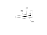
- the stylet hub 520 includes a second surrounding portion 520A capable of surrounding the base end portion 36C of the straight connector 36B on the outer periphery of the straight connector 36B.
- the second surrounding portion 520A is configured to be able to contact the outer surface of the base end portion 36C of the straight connector 36B.
- the second surrounding portion 520A has a shorter length in the longitudinal direction than the extending portion 52A of the stylet hub 52.
- the second surrounding portion 520A is configured to be separated from the first surrounding portion 53B of the connecting member 53 in the radial direction or the radial direction.
- the second surrounding portion 520A corresponds to the second contact portion in this specification.
- the second surrounding portion 520A and the outer surface of the proximal end portion 36C of the straight connector 36B have substantially the same inclination with respect to the longitudinal direction and are in surface contact with each other as shown in FIGS.
- the present invention is not limited to such a configuration, and for example, the second surrounding portion 520C of the stylet hub 520B and the outer surface of the base end portion 36C of the straight connector 36B may be elongated as shown in FIGS.
- the inclination with respect to the direction may be different. In this case, at least one of the two is deformed at different slopes and both of them make circumferential surface contact in the circumferential direction, whereby the seal portion 550A is formed at the surface contact.
- the outer surface 520D of the stylet hub 520, 520B shown in FIGS. 9 and 11 corresponds to the outer surface 52D
- the outer surface 520E corresponds to the outer surface 52E
- the second surrounding portion 520C serves as the second contact portion. Equivalent to.
- the connecting member 53 is configured to rotate independently of the stylet hubs 520 and 520B as in the first embodiment. Therefore, as in the first embodiment, when the stylet 50A is connected to the catheter 30B, the distal end of the catheter 30B is prevented or suppressed from being twisted, and the insertability of the catheter 30B is reduced during percutaneous insertion. Can be prevented or suppressed.
- the stylet hubs 520 and 520B also include second surrounding portions 520A and 520C that abut the straight connector 36B on the proximal end side of the catheter 30B.
- the second surrounding portions 520A and 520C are configured to be spaced apart from the first surrounding portion 53B in the radial direction or the radial direction.
- the second surrounding portion 520A contacts the outer surface of the base end portion 36C of the straight connector 36B to form the seal portion 550, the inner peripheral surface of the straight connector 36B. Contact does not occur. Therefore, even if the inner peripheral surface is subjected to a surface treatment such as a polymer coating, peeling of the coating or the like can be prevented. The same applies to the seal portion 55 in the first embodiment.
- FIG. 13 is a diagram for explaining a main part of a catheter assembly 100B according to Modification 2.
- the catheter assembly 100B according to the modified example 2 is different from the first embodiment and includes a straight connector 36D forming the catheter 30C and a stylet hub 521 forming the stylet 50B.
- the straight connector 36D of Modification 2 includes a tapered surface 36E having a tapered base end.
- Other configurations are substantially the same as those in the first embodiment.
- the stylet hub 521 includes an abutting portion 521A capable of abutting the tapered surface 36E, and the surface contact between the tapered surface 36E and the abutting portion 521A constitutes a seal portion 551 that seals the proximal end side of the catheter 30. It In addition, the contact portion 521A is arranged apart from the first surrounding portion 53B of the connecting member 53 in the radial direction or the radial direction similarly to the first modification.
- the contact portion 521A corresponds to the second contact portion in the present specification
- the outer surface 521D corresponds to the outer surface 52D in the first embodiment
- the outer surface 521E corresponds to the outer surface 52E.
- the connecting member 53 is configured to rotate independently of the stylet hub 521 as in the first embodiment. Therefore, as in the first embodiment, when the stylet 50B is connected to the catheter 30C, the distal end of the catheter 30C is prevented or suppressed from being twisted, and the insertability of the catheter 30C is reduced during percutaneous insertion. Can be prevented or suppressed.
- the stylet hub 521 also includes an abutting portion 521A that abuts the straight connector 36D on the proximal end side of the catheter 30C.
- the contact portion 521A is arranged apart from the first surrounding portion 53B in the radial direction or the radial direction. This prevents or suppresses the occurrence of twist due to the stylet hub 521 being rotated by the connecting member 53 when the connecting member 53 is relatively rotated with respect to the stylet hub 521 as in the first modification. can do.
- the connecting member 53 rotates independently of the stylet hub 521, friction between the proximal end side of the catheter 30 and the contact portion 521A of the stylet hub 521 can be prevented. It is possible to prevent the agent from peeling off.
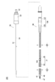
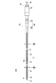
- FIGS. 14 to 16 are views for explaining the configuration of the catheter assembly 200 according to the second embodiment.
- the catheter assembly 200 according to the present embodiment has a percutaneous catheter (hereinafter referred to as “catheter”) 60 different from that of the first embodiment.
- This catheter 60 is a so-called double-lumen catheter, and is configured so that both blood supply and blood removal can be performed at the same time. Therefore, in the present embodiment, the catheter 60 in the extracorporeal circulation device 1 of FIG. 1 has the functions of two catheters, the vein side catheter (blood removal catheter) 5 and the arterial side catheter (blood supply catheter) 6. ..
- a double tube in which a third tube 161 having a first lumen 61 communicating with the blood supply side hole 163 is arranged in the lumen of the second tube 33. It differs from the catheter 30 according to the first embodiment in that it has a tubular structure.
- the pump of the extracorporeal circulation device 1 is operated to remove blood from the patient's vein (caval vein). Then, after performing the gas exchange in the blood by the artificial lung 2 to perform the oxygenation of the blood, the procedure of the vein-vein system (Veno-Venous, VV) for returning the blood to the vein (caval vein) of the patient again is performed. It can be carried out.
- the catheter 60 includes a first tube 32, a second tube 33, a distal tip 41 disposed at the distal end of the first tube 32 and having through holes 46 and 47, and a second tube 33.
- a third tube 161 disposed in the lumen.
- the catheter 60 has a first lumen 61 that functions as a blood supply path and a second lumen 62 that functions as a blood removal path.
- the first lumen 61 is formed in the inner cavity of the third tube 161.
- the second lumen 62 is formed in the inner cavities of the first tube 32 and the second tube 33 and penetrates from the distal end to the proximal end.
- the second tube 33 includes a blood supply side hole 163 that communicates with the first lumen 61 that is a blood supply path, and a blood removal side hole 164 that communicates with the second lumen 62 that is a blood removal path.
- the blood supply side hole 163 and the blood removal side hole 164 have an elliptical shape, but are not limited thereto.
- the third tube 161 is configured to be inserted into the second lumen 62 from the base end side of the second tube 33 and to be connected to the blood supply side hole 163.
- the blood supply side hole 163 is arranged for blood supply in the living body.
- the blood oxygenated by the artificial lung 2 is delivered into the living body through the blood-feeding side hole 163.
- the through holes 46 and 47 and the blood removal side hole 164 provided in the tip 41 are arranged for different blood removal targets in the living body so that blood removal can be performed efficiently. Further, even if the through holes 46, 47 or the blood removal side hole 164 are adsorbed and blocked by the blood vessel wall, blood can be removed from the hole that is not blocked, so that extracorporeal circulation is stabilized. Can be done by
- the catheter 60 is inserted from the internal jugular vein of the neck, and the tip is placed in the inferior vena cava via the superior vena cava and the right atrium.
- the blood supply target is the right atrium, and the blood removal targets are the upper vena cava and the lower vena cava.
- the through holes 46 and 47 of the tip 41 are arranged in the inferior vena cava and the blood removal side hole 164 is arranged in the internal jugular vein with the stylet 50 inserted as shown in FIGS. Is inserted and placed in the living body.
- the first tube 32 is configured to have an inner diameter larger than that of the second tube 33 as in the first embodiment.
- the first tube 32 is placed in the inferior vena cava, which is a relatively thick blood vessel, and the second tube 33 is a femoral vein, which is a relatively thin blood vessel, with the through holes 46, 47 and the side holes 63 being placed in the blood removal target. Is located in.
- the straight connector 136 has a first straight connector 137 and a second straight connector 138, as shown in FIG.
- the first straight connector 137 is configured to communicate with the first lumen 61
- the second straight connector 138 is configured to communicate with the second lumen 62.
- the straight connector 136 is configured as a Y-shaped Y connector formed by branching the first straight connector 137 from the second straight connector 138. Note that, in FIG. 15, the first straight connector 137 and the second straight connector 138 are brought close to each other for convenience of illustration, but the first straight connector 137 and the second straight connector 138 are practically separated from those in FIG. 15. Will be placed.
- the first straight connector 137 is connected to the base end of the third tube 161.
- the second straight connector 138 is coaxially connected to the base end portion of the second tube 33.
- a blood supply tube (blood supply line) is connected to the first straight connector 137, and a blood removal tube (blood removal line) is connected to the second straight connector 138.
- the first straight connector 137 is provided with a male screw portion 137A
- the second straight connector 138 is provided with a male screw portion 138A.
- the first tube 32 is configured to function similarly to the first embodiment.
- the first tube 32 expands and its outer diameter and inner diameter become smaller as shown in FIG. Thereby, the catheter 60 can be inserted into the living body with minimal invasion.
- the first tube 32 contracts in the axial direction as shown in FIG. 14, and the inner diameter of the first tube 32 increases. Thereby, the pressure loss inside the first tube 32 can be reduced.
- the catheter assembly 200 of the present embodiment has the catheter 60, which allows one catheter to perform both blood removal and blood supply functions. Further, as in the first embodiment, when the stylet 50 is connected to the catheter 60, the tip of the catheter 60 is prevented or suppressed from being twisted, and the insertability of the catheter 60 during percutaneous insertion is reduced. Can be prevented or suppressed.
- the present invention is not limited to the above-described embodiments, and various modifications can be made within the scope of the claims.
- the embodiment in which the catheter 30 includes the straight connector 36 has been described.
- the type of connector is not limited to the straight connector as long as it can form a seal portion and can be connected to a mating component.
- a catheter having a blood supply hole is used to send blood after gas exchange to a desired position of a living body.
- the catheter is connected to other parts constituting the circulation circuit after being moved to the target living body lumen.
- the stylet Before the catheter and other parts are connected, the stylet is inserted through the catheter, but the sealability between the catheter and the stylet may be poor, and in such a case, blood may leak. Therefore, it is necessary to secure the sealing property between them.
- a catheter assembly that achieves the above-mentioned object is formed in an elongated shape, and has an expandable and contractible tube provided with a lumen through which blood can flow, and a distal end portion of the tube.
- a catheter having an extendable contact portion, a stylet configured to be insertable into the lumen, and capable of extending the tube in the longitudinal direction by contact with the contact portion, and a base of the catheter.
- a connector that is provided on the end side and that can be connected to the stylet, and a seal portion that is provided between the catheter and the stylet and seals the proximal end side of the catheter, the connector, An engagement portion engageable with the stylet is provided, wherein the stylet connects the hub disposed on the proximal end side of the catheter, the hub and the connector, and engages with the engagement portion.
- a possible connecting member that is provided on the end side and that can be connected to the stylet, and a seal portion that is provided between the catheter and the stylet and seals the proximal end side of the catheter, the connector, An engagement portion engageable with the stylet is provided, wherein the stylet connects the hub disposed on the proximal end side of the catheter, the hub and the connector, and engages with the engagement portion.
- the seal portion that seals the proximal end side of the catheter is provided between the catheter and the stylet, the sealing property between them is secured.
- FIG. 1 is a diagram showing an example of an extracorporeal circulation device to which a catheter provided in a catheter assembly according to an embodiment of the present invention is applied.
- the extracorporeal circulation device can be used for, for example, percutaneous cardiopulmonary support (PCPS), which temporarily assists or substitutes the functions of the heart and lungs until the heart function is restored when the patient's heart is weak. ..
- PCPS percutaneous cardiopulmonary support
- the extracorporeal circulation device 1 can be used for a venous-arterial (Veno-Arterial, VA) procedure.
- the venous-arterial system (Veno-Arterial, VA) is a method in which a pump is operated to remove blood from a patient's vein (for example, the vena cava), and gas is exchanged in the blood by the artificial lung 2 to oxygenate blood. After conversion, this blood is returned to the patient's artery (eg, aorta).
- the extracorporeal circulation device 1 can be used as a device for assisting the heart and lungs of a patient.
- extracorporeal circulation a procedure of removing blood from a patient, performing a predetermined treatment outside the body, and then sending blood to the body of the patient again is referred to as “extracorporeal circulation”.
- the extracorporeal circulation device 1 has a circulation circuit for circulating blood.
- the circulation circuit includes an artificial lung 2, a centrifugal pump 3, a drive motor 4 that is a driving means for driving the centrifugal pump 3, a vein side catheter (percutaneous catheter for blood removal) 5, and a control unit.
- the controller 10 is included.
- the venous catheter (for blood removal) catheter 5 is inserted from the femoral vein, and the tip of the venous catheter 5 is placed in the right atrium via the inferior vena cava.
- the vein side catheter 5 is connected to the centrifugal pump 3 via a blood removal tube (blood removal line) 11.
- the blood removal tube 11 is a conduit for sending blood.
- the arterial catheter (blood supply catheter) 6 is inserted from the femoral artery.
- the drive motor 4 operates the centrifugal pump 3 based on the command SG from the controller 10.
- the centrifugal pump 3 passes the blood removed from the blood removal tube 11 through the artificial lung 2, and then returns the blood to the patient P via the blood supply tube (blood supply line) 12.
- the artificial lung 2 is arranged between the centrifugal pump 3 and the blood supply tube 12.
- the artificial lung 2 performs gas exchange (oxygen addition and/or carbon dioxide removal) for blood.
- a membrane oxygenator can be used, and particularly preferably, a hollow fiber membrane oxygenator can be used.
- Oxygen gas is supplied from the oxygen gas supply unit 13 to the artificial lung 2 through the tube 14.
- the blood supply tube 12 is a conduit connecting the artificial lung 2 and the arterial catheter 6.
- a conduit made of a synthetic resin such as vinyl chloride resin or silicone rubber, which has high transparency and is elastically deformable and flexible, can be used.
- a synthetic resin such as vinyl chloride resin or silicone rubber, which has high transparency and is elastically deformable and flexible
- the detection sensor 20 is arranged in the middle of the blood removal tube 11.
- a fast clamp 17 is arranged in the middle of the blood supply tube 12.
- the detection sensor 20 detects the mixed bubbles by ultrasonic waves when the bubbles are mixed in the circuit due to an erroneous operation of the three-way stopcock 18 or a tube breakage during extracorporeal circulation.
- the detection sensor 20 detects that there is an air bubble in the blood sent into the blood removal tube 11
- the detection sensor 20 sends a detection signal to the controller 10.
- the controller 10 issues an alarm warning and lowers the rotation speed of the centrifugal pump 3 or stops the centrifugal pump 3.
- the controller 10 instructs the fast clamp 17 to immediately close the blood supply tube 12 by the fast clamp 17. This prevents bubbles from being sent into the body of the patient P.
- the controller 10 controls the operation of the extracorporeal circulation device 1 to prevent air bubbles from entering the body of the patient P.
- a pressure sensor is provided on the tubes 11 (12, 19) of the circulation circuit of the extracorporeal circulation device 1.
- the pressure sensor is, for example, of the attachment position A1 of the blood removal tube 11, the attachment position A2 of the blood supply tube 12 of the circulation circuit, or the attachment position A3 of the connection tube 19 connecting between the centrifugal pump 3 and the artificial lung 2. Can be placed in at least one place.
- the pressure sensor measures the pressure inside each of the tubes 11, 12, and 19 while the extracorporeal circulation device 1 is performing extracorporeal circulation on the patient P.
- the mounting position of the pressure sensor is not limited to the mounting positions A1, A2, A3, and may be mounted at any position in the circulation circuit.
- the catheter assembly 100 according to this embodiment includes a catheter 30 and a stylet 50.
- the catheter 30 is used as the vein side catheter (blood removal catheter) 5 in FIG.
- the catheter 30 has a catheter tube 31 (corresponding to a “tube”) having a side hole 63, and a distal tip provided at the tip of the catheter tube 31 and having through holes 46 and 47. 41.
- the catheter 30 includes a clamp tube 34 arranged on the proximal end side of the catheter tube 31, a catheter connector 35 connecting the catheter tube 31 and the clamp tube 34, and a straight connector 36 (corresponding to a “connector”). Have.
- the side to be inserted into the living body is referred to as the “tip” or “tip side”, and the side operated by the operator is referred to as “base end” or “base end side”.
- the tip portion means a certain range including the tip (the most distal end) and its periphery
- the base end portion means a certain range including the base end (the most proximal end) and its periphery.
- the catheter 30 has a lumen 30A penetrating from the distal end to the proximal end as shown in FIG.
- the through holes 46 and 47 of the tip 41 and the side holes 63 of the catheter tube 31 are arranged for different blood removal targets in the living body so that blood removal can be performed efficiently.
- a stylet 50 is used when inserting the catheter 30 into the living body as shown in FIG.
- the stylet 50 is inserted through the lumen 30A of the catheter 30, and the catheter 30 and the stylet 50 are integrated in advance and inserted into the living body. Blood is allowed to flow in the lumen 30A. The method of using the catheter 30 will be described later.
- the catheter tube 31 is configured to be elongated and expandable.
- the catheter tube 31 has a first tube 32 and a second tube 33 arranged on the proximal end side of the first tube 32, as shown in FIG. 2.
- the first tube 32 is configured to have higher elasticity than the second tube 33.
- the first tube 32 has a larger outer diameter and inner diameter than the second tube 33.
- the first tube 32 and the second tube 33 are integrally formed and have a substantially constant wall thickness.
- the lengths of the first tube 32 and the second tube 33 are configured to be the lengths necessary for arranging the through holes 46, 47 and the side hole 63 of the distal tip 41 on a desired blood removal target.
- the length of the first tube 32 can be, for example, 20 to 40 cm
- the length of the second tube 33 can be, for example, 20 to 30 cm.
- the side hole 63 is a hole that penetrates the side surface of the second tube 33 and is opened so as to communicate with the lumen 30A of the catheter 30.
- the side hole 63 functions as a blood removal hole. It is preferable to provide a plurality of side holes 63 because blood can be removed from the other side holes even if any of the side holes 63 is adsorbed to the blood vessel wall and blocked, and stable extracorporeal circulation can be performed.
- blood removal targets are the right atrium and the inferior vena cava.
- the catheter 30 is inserted and left in the living body so that the through holes 46 and 47 of the tip 41 are arranged in the right atrium.
- the first tube 32 is placed in the inferior vena cava, which is a relatively thick blood vessel, and the second tube 33 is a femoral vein, which is a relatively thin blood vessel, with the through holes 46, 47 and the side holes 63 being placed in the blood removal target. Is located in.
- the highly stretchable first tube 32 extends in the axial direction and the outer diameter and inner diameter of the first tube 32 become smaller.
- the outer diameter and inner diameter of the first tube 32 are substantially the same as the outer diameter and inner diameter of the second tube 33. Since the catheter 30 is inserted into the living body in a state where the first tube 32 is extended in the axial direction and the outer diameter is reduced, the catheter 30 can be inserted minimally invasively.
- the first tube 32 contracts in the axial direction and the outer diameter and the inner diameter of the first tube 32 are reduced as shown in FIG. growing.
- the first tube 32 is arranged in the inferior vena cava, which is a relatively thick blood vessel, the outer diameter of the first tube 32 can be increased.
- the pressure loss when blood or the like flows through the first tube 32 can be reduced by increasing the inner diameter of the first tube 32.
- the pressure loss is reduced, the flow rate of blood flowing through the circulation circuit increases. Therefore, in order to obtain a sufficient blood circulation amount, it is necessary to make the inner diameter of the first tube 32 sufficiently large.
- the inner diameter of the first tube 32 may be, for example, 9 to 11 mm, and the inner diameter of the second tube 33 may be, for example, 4 to 8 mm.
- the wall thickness of the first tube 32 and the second tube 33 can be set to 0.3 to 0.5 mm, for example.
- the distal end portion and the proximal end portion of the first tube 32 are tapered portions that gradually become thinner from the center in the longitudinal direction of the first tube 32 toward the distal end portion and the proximal end portion. Are preferably formed. Thereby, the inner diameters of the distal end and the proximal end of the first tube 32 can easily be continuously connected to the inner diameter of the distal end tip 41 disposed on the distal end side and the inner diameter of the second tube 33 disposed on the proximal end side. it can.
- the catheter tube 31 includes a tubular reinforcing body 320 braided in a mesh shape so as to intersect the wires W, and a first resin layer 331 and a second resin layer provided so as to cover the reinforcing body 320. And a layer 332.
- the first tube 32 is composed of the distal end 320 a of the reinforcing body 320 and the first resin layer 331
- the second tube 33 is composed of the proximal end 320 b of the reinforcing body 320 and the second resin layer 332.
- Innumerable gaps or openings are formed in the reinforcing body 320 by braiding a plurality of wires W.
- the size relation of the plurality of gaps is not particularly limited.
- the second resin layer 332 is formed so as to cover the inner peripheral surface of the opening of the reinforcing body 320. This can prevent the wire from being exposed from the inner peripheral surface of the side hole 63.
- the maximum length of the opening can be set to about 2 or 3 mm.
- the wire W forming the reinforcing body 320 is made of a shape memory material such as a known shape memory metal or shape memory resin.
- a shape memory material such as a known shape memory metal or shape memory resin.
- shape memory metal for example, titanium-based (Ti-Ti, Ti-Pd, Ti-Nb-Sn, etc.) or copper-based alloy can be used.
- shape memory resin for example, acrylic resin, transisoprene polymer, polynorbornene, styrene-butadiene copolymer, polyurethane can be used.
- the cross-sectional shape of the wire W forming the reinforcing body 320 is rectangular in the present embodiment. However, the shape is not limited to this, and may be a square, a circle, an ellipse, or the like other than the above. When the cross-sectional shape is circular, the wire diameter of the wire W may be, for example, 0.1 mm to 0.2 mm.
- the first resin layer 331 forming the first tube 32 is made of a material softer than the second resin layer 332 forming the second tube 33. With this configuration, the first tube 32 can be made softer than the second tube 33, and the elasticity can be enhanced.
- the material forming the first resin layer 33 a known resin that is relatively soft can be used.
- urethane, polyurethane, silicon, or vinyl chloride having a low hardness can be used.
- the material forming the second resin layer 332 for example, urethane, polyurethane, silicon, or vinyl chloride having high hardness can be used.
- hydrophilic coating may be applied to the surface. This increases the lubricity of the surface of the catheter tube 31, facilitates insertion into the living body, improves operability, and prevents damage to the blood vessel wall. In addition, blood and proteins are less likely to adhere, and it can be expected to prevent the formation of thrombus.
- the tip 41 is fixed to the tip of the first tube 32. As shown in FIG. 6, the tip 41 has a tapered shape whose diameter is gradually reduced toward the tip side. As shown in FIG. 6, the distal tip 41 has a base portion 49 that is inserted into the distal end of the first tube 32, a plurality of through holes 46 provided in the side surface, and a through hole 47 provided at the distal end of the distal tip 41. Have. The through holes 46 and 47 function as blood removal holes. The through hole 47 of the tip 41 is configured to communicate with the lumen 30A of the catheter 30.
- the tip 41 can be formed of, for example, hard plastic or the like.
- a flat receiving surface 48 (a "contact portion") that abuts a flat surface 50a of the stylet 50 used prior to insertion of the catheter 30 into the living body. Equivalent) is formed. As will be described later, the tip of the stylet 50 abuts the receiving surface 48, whereby the catheter 30 extends in the longitudinal direction.
- the clamp tube 34 is provided on the base end side of the second tube 33.
- a lumen through which the stylet 50 can be inserted is provided inside the clamp tube 34.
- the clamp tube 34 can be formed using the same material as the catheter tube 31.
- the catheter connector 35 connects the second tube 33 and the clamp tube 34.
- a lumen through which the stylet 50 can be inserted is provided inside the catheter connector 35.
- the straight connector 36 is provided on the proximal end side of the catheter 30.
- the straight connector 36 is connected to the proximal end side of the clamp tube 34.
- the straight connector 36 has a circular cross section at the base end that intersects the longitudinal direction.
- a lumen through which the stylet 50 can be inserted is provided inside the straight connector 36.
- a male screw portion 36A (corresponding to "engaging portion") capable of engaging with the female screw portion 53C of the stylet 50 is provided on the outer circumference of the straight connector 36.
- the straight connector 36 is configured to be connectable to the stylet 50 by the male screw portion 36A.
- the stylet 50 includes a stylet tube 51 provided to extend in the axial direction as shown in FIG. 2, a stylet hub 52 (corresponding to a “hub”) to which a base end of the stylet tube 51 is fixed, have.
- the stylet 50 has a connecting member 53 that is provided on the tip side of the stylet hub 52 and connects the stylet hub 52 and the straight connector 36.
- the stylet tube 51 is an elongated body that extends in the axial direction and has relatively high rigidity.
- the stylet tube 51 is configured to be insertable into the lumen 30A of the catheter 30.
- the overall length of the stylet tube 51 along the axial direction is longer than the overall length of the catheter 30 along the axial direction.
- the stylet tube 51 includes a guide wire lumen 54 into which a guide wire (not shown) can be inserted (see FIG. 5).
- the stylet tube 51 is guided by the guide wire and inserted into the living body together with the catheter 30.
- the stylet tube 51 is removed from the catheter 30 by leaving the catheter 30 in the living body and then withdrawing the stylet hub 52 to the proximal end side.
- the tip of the stylet tube 51 is provided with a flat surface 50a that abuts the receiving surface 48 of the tip 41, as shown in FIG.
- the stylet tube 51 has relatively high rigidity and is provided with a stiffness that allows the pushing force to the distal end side by the operation at hand to be transmitted to the distal end tip 41. Therefore, in the stylet tube 51, the flat surface 50a is brought into contact with the receiving surface 48 of the distal end tip 41 and the distal end tip 41 is pushed toward the distal end side, whereby the catheter tube 31 is elongated in the longitudinal direction and a narrow blood vessel is formed. Plays a role of expansion.
- the stylet hub 52 is arranged on the proximal end side of the catheter 30 when the catheter 30 is connected to the stylet 50. As shown in FIG. 7, the stylet hub 52 includes an extending portion 52A that extends along the first surrounding portion 53B of the connecting member 53, which will be described later, in the outer circumferential direction of the stylet hub 52.
- the extending portion 52A is formed in a hollow circular shape in a cross section that intersects with the longitudinal direction.
- the connecting member 53 is a first enclosing member extending in the longitudinal direction so as to enclose between the attaching portion 53A attached to the stylet hub 52 and the male screw portion 36A (engaging portion).
- the unit 53B is provided.
- the extending portion 52A extends along the first surrounding portion 53B and contacts the male screw portion 36A (engaging portion).
- a seal portion 55 that seals the proximal end side of the catheter 30 is configured between the catheter 30 and the stylet 50.
- the connecting member 53 includes a female screw portion 53C, which is screwed with the male screw portion 36A, on the tip side of the first surrounding portion 53B.
- the female screw portion 53C relatively connects the connecting member 53 to the straight connector 36. It is configured to be engageable with the male screw portion 36A by rotating.
- FIG. 2 shows a state before inserting the stylet tube 51 of the stylet 50 into the lumen 30A of the catheter 30
- FIG. 4 shows a state after inserting the stylet tube 51 into the lumen 30A of the catheter 30.
- an operator such as a doctor inserts the stylet tube 51 of the stylet 50 into the lumen 30A of the catheter 30.
- the stylet tube 51 passes through the straight connector 36, the clamp tube 34, the catheter connector 35, the second tube 33, and the first tube 32 in order.
- the flat surface 50a of the stylet tube 51 contacts the receiving surface 48 of the tip 41 (see FIG. 5).
- the overall length of the stylet tube 51 in the axial direction is longer than the overall length of the catheter 30 in the axial direction. Therefore, the flat tip 50a of the stylet tube 51 is pressed toward the tip side of the tip tip 41 while being in contact with the receiving surface 48 of the tip tip 41. As a result, the tip of the first tube 32 fixed to the tip 41 is pulled toward the tip side.
- the catheter 30 receives a force in the extending direction, and the first tube 32 of the catheter 30, which has relatively high elasticity, extends in the axial direction.
- the outer diameter of the first tube 32 becomes smaller and becomes substantially the same as the outer diameter of the second tube 33.
- the proximal end of the catheter 30 and the stylet hub 52 are fixed with the first tube 32 extended in the axial direction.
- the proximal end of the catheter 30 and the stylet hub 52 are fixed by rotating the connecting member 53 and engaging the female screw portion 53C and the male screw portion 36A.
- the operator inserts the catheter 30 having the stylet tube 51 inserted through it along a guide wire (not shown) that is previously inserted into the target site in the living body.
- the outer diameter of the first tube 32 becomes substantially the same as the outer diameter of the second tube 33 by inserting the stylet 50 into the catheter 30. Therefore, the catheter 30 can be inserted into the living body with minimal invasion.
- the operator inserts the catheter 30 into the living body and indwells until the through holes 46 and 47 of the distal tip 41 are located in the right atrium and the side hole 63 is located in the inferior vena cava.
- the first tube 32 is placed in the inferior vena cava, which is a relatively thick blood vessel, and the second tube 33 is a thigh, which is a relatively thin blood vessel, with the through holes 46, 47 and the side holes 63 being placed in the blood removal target. Placed in a vein.
- the operator removes the stylet tube 51 and the guide wire from the catheter 30.
- the stylet tube 51 and the guide wire are once pulled out to the position of the straight connector 36 of the catheter 30 and clamped by forceps (not shown), and then completely removed from the catheter 30.
- the catheter 30 is released from the force in the axially extending direction received from the stylet 50. Therefore, the first tube 32 contracts in the axial direction, and the outer diameter and the inner diameter of the first tube 32 increase. As a result, the pressure loss inside the first tube 32 can be reduced.
- the operator connects the straight connector 36 of the catheter 30 to the blood removal tube 11 of the extracorporeal circulation device 1 of FIG. After confirming that the connection of the catheter on the blood supply side is completed, the forceps of the clamp tube 34 is released to start the extracorporeal circulation.
- the operator removes the catheter 30 from the blood vessel, and hemostasis repair is performed at the insertion site by a surgical procedure as necessary.
- the catheter assembly 100 has the catheter 30 and the stylet 50, and the seal portion 55 that seals the proximal end side of the catheter 30 is provided between them.
- the catheter 30 includes a catheter tube 31, a receiving surface 48, and a straight connector 36.
- the catheter tube 31 is formed in an elongated shape, is provided with a lumen 30A through which blood can flow, and is expandable and contractable.
- the receiving surface 48 is provided at the distal end portion of the catheter tube 31, and is configured so that the contact surface 48 allows the catheter tube 31 to extend in the longitudinal direction.
- the straight connector 36 is provided on the proximal end side of the catheter 30 and is configured to be connectable to the stylet 50.
- the straight connector 36 includes a male screw portion 36A that can be engaged with the stylet 50.
- the stylet 50 is configured to be insertable into the lumen 30A, is capable of extending the catheter tube 31 in the longitudinal direction by contact with the receiving surface 48, and includes a stylet hub 52 and a connecting member 53.
- the stylet hub 52 is arranged on the proximal side of the catheter 30.
- the connecting member 53 connects the stylet hub 52 and the straight connector 36, and is configured to be engageable with the male screw portion 36A.
- the seal portion 55 that seals the proximal end side of the catheter 30 is provided between the catheter 30 and the stylet 50, the sealing property between the catheter 30 and the stylet 50 is ensured.
- the connecting member 53 also includes a first enclosing portion 53B extending in the longitudinal direction so as to enclose between the attachment portion 53A attached to the stylet hub 52 and the male screw portion 36A of the straight connector 36.
- the stylet hub 52 is provided with an extending portion 52A that is formed in a circular shape in a cross section that intersects in the longitudinal direction and that extends along the first surrounding portion 53B on the outer side in the circumferential direction of the stylet hub 52.
- the seal portion 55 can be formed by surface contact between the male screw portion 36A and the extending portion 52A.
- Modification 1 Next, with reference to FIG. 8, a catheter assembly 100A according to Modification 1 will be described. 8 to 12 are diagrams for explaining the main part of the catheter assembly 100A according to the first modification.
- the catheter assembly 100A according to the first modification includes a straight connector 36B forming the catheter 30B and a stylet hub 520 forming the stylet 50A, unlike the first embodiment.
- Other configurations are substantially the same as those in the first embodiment, and the overlapping description here is basically omitted.
- the shape of the base end portion 36C is linearly formed from the base end portion of the straight connector 36.
- the straight connector 36B has a circular cross section that intersects the longitudinal direction at the base end portion 36C.
- the stylet hub 520 includes a second surrounding portion 520A capable of surrounding the base end portion 36C of the straight connector 36 on the outer circumference of the straight connector 36.
- the second surrounding portion 520A is configured to be able to contact the outer surface of the base end portion 36C of the straight connector 36B.
- the second surrounding portion 520A and the outer surface of the proximal end portion 36C of the straight connector 36B have substantially the same inclination with respect to the longitudinal direction and are in surface contact with each other as shown in FIGS.
- the present invention is not limited to such a configuration, and for example, the second surrounding portion 520C of the stylet hub 520B and the outer surface of the base end portion 36C of the straight connector 36B may be elongated as shown in FIGS.
- the inclination with respect to the direction may be different. In this case, at least one of the two is deformed at different slopes and both of them make circumferential surface contact in the circumferential direction, whereby the seal portion 550A is formed at the surface contact.
- the straight connector 36 has a circular cross section at the base end that intersects the longitudinal direction.
- the stylet hub 52 includes a second enclosing portion 520A that is capable of enclosing the proximal end portion of the straight connector 36 on the outer periphery of the straight connector 36 and is in contact with the outer surface of the proximal end portion of the straight connector 36.
- the seal portion 550 can also be configured by surface contact between the second surrounding portion 520A and the outer surface of the straight connector 36.
- the inner peripheral surface of the straight connector 36B is No contact occurs. Therefore, even if the inner peripheral surface is subjected to a surface treatment such as a polymer coating, peeling of the coating or the like can be prevented. The same applies to the seal portion 55 in the first embodiment.
- FIG. 13 is a diagram for explaining a main part of a catheter assembly 100B according to Modification 2.
- the catheter assembly 100B according to the modified example 2 is different from the first embodiment and includes a straight connector 36D forming the catheter 30C and a stylet hub 521 forming the stylet 50B.
- the straight connector 36D of Modification 2 includes a tapered surface 36E having a tapered base end.
- Other configurations are substantially the same as those in the first embodiment.
- the stylet hub 521 includes a contact surface 521A that can come into contact with the tapered surface 36E, and the seal portion 551 that seals the proximal end side of the catheter 30 is configured by the surface contact between the tapered surface 36E and the contact surface 521A.
- the straight connector 36D includes the tapered surface 36E in which the base end portion is formed in a tapered shape.
- the stylet hub 521 includes a contact surface 521A that can abut the tapered surface 36E of the straight connector 36D.
- the seal portion 551 can ensure the sealability as in the first embodiment and the like by the surface contact between the tapered surface 36E and the contact surface 521A.
- FIGS. 14 to 16 are views for explaining the configuration of the catheter assembly 200 according to the fourth embodiment.
- the catheter assembly 200 according to the present embodiment has a percutaneous catheter (hereinafter referred to as “catheter”) 60 different from that of the third embodiment.
- catheter percutaneous catheter
- This catheter 60 is a so-called double-lumen catheter, and is configured so that both blood supply and blood removal can be performed at the same time. Therefore, in the present embodiment, the catheter 60 in the extracorporeal circulation device 1 of FIG. 1 has the functions of two catheters, the vein side catheter (blood removal catheter) 5 and the arterial side catheter (blood supply catheter) 6. ..
- a double tube in which a third tube 161 having a first lumen 61 communicating with the blood supply side hole 163 is arranged in the lumen of the second tube 33. It differs from the catheter 30 according to the first embodiment in that it has a tubular structure.
- the pump of the extracorporeal circulation device 1 is operated to remove blood from the patient's vein (caval vein). Then, after performing the gas exchange in the blood by the artificial lung 2 to perform the oxygenation of the blood, the procedure of the vein-vein system (Veno-Venous, VV) for returning this blood to the vein (cava) of the patient again It can be carried out.
- Veno-Venous VV
- the catheter 60 includes a first tube 32, a second tube 33, a distal tip 41 disposed at the distal end of the first tube 32 and having through holes 46 and 47, and a second tube 33.
- a third tube 161 disposed in the lumen.
- the catheter 60 has a first lumen 61 that functions as a blood supply path and a second lumen 62 that functions as a blood removal path.
- the first lumen 61 is formed in the inner cavity of the third tube 161.
- the second lumen 62 is formed in the inner cavities of the first tube 32 and the second tube 33 and penetrates from the distal end to the proximal end.
- the second tube 33 includes a blood supply side hole 163 that communicates with the first lumen 61 that is a blood supply path, and a blood removal side hole 164 that communicates with the second lumen 62 that is a blood removal path.
- the blood supply side hole 163 and the blood removal side hole 164 have an elliptical shape, but are not limited thereto.
- the third tube 161 is configured to be inserted into the second lumen 62 from the base end side of the second tube 33 and to be connected to the blood supply side hole 163.
- the blood supply side hole 163 is arranged for blood supply in the living body.
- the blood oxygenated by the artificial lung 2 is delivered into the living body through the blood-feeding side hole 163.
- the through holes 46 and 47 and the blood removal side hole 164 provided in the tip 41 are arranged for different blood removal targets in the living body so that blood removal can be performed efficiently. Further, even if the through holes 46, 47 or the blood removal side hole 164 are adsorbed and blocked by the blood vessel wall, blood can be removed from the hole that is not blocked, so that extracorporeal circulation is stabilized. Can be done by
- the catheter 60 is inserted from the internal jugular vein of the neck, and the tip is placed in the inferior vena cava via the superior vena cava and the right atrium.
- the blood supply target is the right atrium, and the blood removal targets are the upper vena cava and the lower vena cava.
- the through holes 46 and 47 of the tip 41 are arranged in the inferior vena cava and the blood removal side hole 164 is arranged in the internal jugular vein with the stylet 50 inserted as shown in FIGS. Is inserted and placed in the living body.
- the first tube 32 is configured to have an inner diameter larger than that of the second tube 33 as in the first embodiment.
- the first tube 32 is placed in the inferior vena cava, which is a relatively thick blood vessel, and the second tube 33 is a femoral vein, which is a relatively thin blood vessel, with the through holes 46, 47 and the side holes 63 being placed in the blood removal target. Is located in.
- the straight connector 136 has a first straight connector 137 and a second straight connector 138, as shown in FIG.
- the first straight connector 137 is configured to communicate with the first lumen 61
- the second straight connector 138 is configured to communicate with the second lumen 62.
- the straight connector 136 is configured as a Y-shaped Y connector formed by branching the first straight connector 137 from the second straight connector 138. Note that, in FIG. 15, the first straight connector 137 and the second straight connector 138 are brought close to each other for convenience of illustration, but the first straight connector 137 and the second straight connector 138 are practically separated from those in FIG. 15. Will be placed.
- the first straight connector 137 is connected to the base end of the third tube 161.
- the second straight connector 138 is coaxially connected to the base end portion of the second tube 33.
- a blood supply tube (blood supply line) is connected to the first straight connector 137, and a blood removal tube (blood removal line) is connected to the second straight connector 138.
- the first straight connector 137 is provided with a male screw portion 137A
- the second straight connector 138 is provided with a male screw portion 138A.
- the first tube 32 is configured to function similarly to the first embodiment.
- the first tube 32 expands and its outer diameter and inner diameter become smaller as shown in FIG. Thereby, the catheter 60 can be inserted into the living body with minimal invasion.
- the first tube 32 contracts in the axial direction as shown in FIG. 14, and the inner diameter of the first tube 32 increases. Thereby, the pressure loss inside the first tube 32 can be reduced.
- the catheter assembly 200 of the present embodiment has the catheter 60, which allows one catheter to perform both blood removal and blood supply functions.
- the present invention is not limited to the above-described embodiments, and various modifications can be made within the scope of the claims.
- the embodiment in which the catheter 30 includes the straight connector 36 has been described.
- the type of connector is not limited to the straight connector as long as it can form a seal portion and can be connected to a mating component.
Landscapes
- Health & Medical Sciences (AREA)
- Heart & Thoracic Surgery (AREA)
- Life Sciences & Earth Sciences (AREA)
- Engineering & Computer Science (AREA)
- Hematology (AREA)
- General Health & Medical Sciences (AREA)
- Anesthesiology (AREA)
- Biomedical Technology (AREA)
- Veterinary Medicine (AREA)
- Public Health (AREA)
- Animal Behavior & Ethology (AREA)
- Cardiology (AREA)
- Pulmonology (AREA)
- Vascular Medicine (AREA)
- Biophysics (AREA)
- Mechanical Engineering (AREA)
- Emergency Medicine (AREA)
- Media Introduction/Drainage Providing Device (AREA)
- Infusion, Injection, And Reservoir Apparatuses (AREA)
Abstract
【課題】カテーテルとスタイレットとを接続する際にカテーテルに生じる捩れを防止又は抑制することによって経皮的挿入を行う際のカテーテルの挿入性の低下を防止又は抑制するカテーテル組立体を提供する。 【解決手段】カテーテル組立体100は、ルーメン30Aを設けた伸縮可能なチューブ31と、チューブの先端部に設けられた当接部48と、を備えたカテーテル30と、前記ルーメンに挿入可能で当接部との当接によってチューブを長手方向に伸長可能なスタイレット50と、カテーテルの基端側に設けられスタイレットと連結可能なストレートコネクタ36と、を有し、コネクタは、スタイレットと係合可能な雄ネジ部36Aを備え、スタイレットは、カテーテルの基端側に配置されるスタイレットハブ52と、スタイレットハブとストレートコネクタとを連結し、かつスタイレットハブと独立して回転することによって雄ネジ部と係合可能な連結部材53と、を備える。
Description
本発明は、血液を生体に送血する送血孔を備えるカテーテル組立体に関する。
従来から、救急治療における心肺蘇生や、循環補助、呼吸補助を行うため、経皮的心肺補助法(PCPS:percutaneous cardiopulmonary support)による治療が行われている。この経皮的心肺補助法とは、体外循環装置を用いて、一時的に心肺機能の補助・代行を行う方法である。また、開心術においても同様に体外循環装置が用いられる。
体外循環装置は、遠心ポンプ、人工肺、脱血路および送血路等から構成される体外循環回路を備え、脱血した血液に対してガス交換を行い送血路へ送血するものである。これに関連して、例えば下記の特許文献1には、体外循環装置の循環回路が記載されている。
このような循環回路では、生体の所望の位置にガス交換後の血液を送血するために、送血孔(流出孔)を備えるカテーテルが使用される。カテーテルは、体外循環を行うために生体内の所定の位置に配置して使用される。また、カテーテルは、所定の位置への配置を行い易くするために径方向及び軸方向(長手方向)への伸縮が可能なものが使用されるとともに、カテーテルの生体管腔移動時の形状を規制するためにスタイレット等といった医療器具を共に使用する場合がある。スタイレットは、カテーテルの生体管腔挿入時にカテーテルの軸方向に張力をかけて伸長させることによって、径方向に収縮させる機能等を備える。カテーテルとスタイレットは、ネジ等の螺旋形状を係合させることによって固定される場合がある。
ここで、上記のようにスタイレットによってカテーテルの長手方向に張力が働いた状態でカテーテルとスタイレットとの螺旋形状による係合をスタイレットの回転によって行おうとすると、スタイレットの回転につられてカテーテルの先端等が捩れる虞がある。このように上記捩れが生じると、カテーテルの回転による負荷がかかり続け、経皮的挿入を行う際のカテーテルの挿入性が低下する虞がある。
そこで、本発明は、カテーテルとスタイレットとを接続する際にカテーテルに生じる捩れを防止又は抑制することによって経皮的挿入を行う際のカテーテルの挿入性の低下を防止又は抑制するカテーテル組立体を提供することを目的とする。
上記目的を達成するカテーテル組立体は、長尺状に形成され、血液を流通可能なルーメンを設けた伸縮可能なチューブと、前記チューブの先端部に設けられ、当接によって前記チューブを長手方向に伸長可能な第1当接部と、を備えたカテーテルと、前記ルーメンに挿入可能に構成され、前記第1当接部との当接によって前記チューブを前記長手方向に伸長可能なスタイレットと、前記カテーテルの基端側に設けられ、前記スタイレットと連結可能なコネクタと、を有し、前記コネクタは、前記スタイレットと係合可能な第1係合部を備え、前記スタイレットは、前記カテーテルの基端側に配置されるハブと、前記ハブと前記コネクタとを連結し、かつ前記ハブと独立して回転することによって前記第1係合部と係合可能な連結部材と、を備える。
上記のように構成したカテーテル組立体によれば、スタイレットが、ハブと独立して回転することによって第1係合部と係合可能な連結部材を備えるように構成している。これにより、スタイレットの連結部材を回転させてもスタイレットのハブには回転が伝わらない、又はほとんど伝わらないようになるため、カテーテルに捩れが生じることを防止又は抑制できる。そのため、経皮的挿入を行う際のカテーテルの挿入性の低下を防止又は抑制することができる。
以下、添付した図面を参照しながら、本発明の実施形態を説明する。図1は、本発明の実施形態に係るカテーテル組立体に備えられるカテーテルが適用された体外循環装置の一例を示す図である。体外循環装置は、例えば、患者の心臓が弱っているときに心機能が回復するまでの間、一時的に心臓と肺の機能を補助・代行する経皮的心肺補助法(PCPS)に使用できる。
体外循環装置1は、静脈-動脈方式(Veno-Arterial,VA)の手技に利用することができる。静脈-動脈方式(Veno-Arterial,VA)とは、ポンプを作動して患者の静脈(例えば、大静脈)から血液を脱血し、人工肺2により血液中のガス交換を行って血液の酸素化を行った後に、この血液を患者の動脈(例えば、大動脈)に戻す手技を指す。このように、体外循環装置1は、患者の心臓と肺の補助を行う装置として使用できる。以下、患者から脱血して体外で所定の処置を施した後、再び患者の体内に送血する手技を「体外循環」と称する。
図1に示すように、体外循環装置1は、血液を循環させる循環回路を有している。循環回路は、人工肺2と、遠心ポンプ3と、遠心ポンプ3を駆動するための駆動手段であるドライブモータ4と、静脈側カテーテル(脱血用の経皮カテーテル)5と、制御部としてのコントローラ10と、を有している。
静脈側カテーテル(脱血用)カテーテル5は、大腿静脈より挿入され、下大静脈を介して静脈側カテーテル5の先端が右心房に留置される。静脈側カテーテル5は、脱血チューブ(脱血ライン)11を介して遠心ポンプ3に接続されている。脱血チューブ11は、血液を送る管路である。
動脈側カテーテル(送血用カテーテル)6は、大腿動脈より挿入される。
ドライブモータ4は、コントローラ10の指令SGに基づいて遠心ポンプ3を作動させる。遠心ポンプ3は、脱血チューブ11から脱血した血液を人工肺2に通した後に、送血チューブ(送血ライン)12を介して患者Pに血液を戻す。
人工肺2は、遠心ポンプ3と送血チューブ12との間に配置されている。人工肺2は、血液に対するガス交換(酸素付加及び/又は二酸化炭素除去)を行う。人工肺2としては、例えば膜型人工肺を用いることができ、特に好ましくは中空糸膜型人工肺を用いることができる。人工肺2には、酸素ガス供給部13から酸素ガスがチューブ14を通じて供給される。送血チューブ12は、人工肺2と動脈側カテーテル6を接続している管路である。
脱血チューブ11及び送血チューブ12は、例えば塩化ビニル樹脂やシリコーンゴム等の透明性の高い、弾性変形可能な可撓性を有する合成樹脂製の管路を使用することができる。脱血チューブ11内では、液体である血液はV1方向に流れ、送血チューブ12内では血液はV2方向に流れる。
図1に示す循環回路では、検出センサ20が脱血チューブ11の途中に配置されている。送血チューブ12の途中にはファストクランプ17が配置されている。
検出センサ20は、体外循環中に三方活栓18の誤操作やチューブの破損等により回路内に気泡が混入された場合に、混入された気泡を超音波によって検出する。検出センサ20が脱血チューブ11内に送られている血液中に気泡があることを検出した場合、検出センサ20はコントローラ10に検出信号を送る。コントローラ10は、この検出信号に基づいてアラームによる警報を報知するとともに、遠心ポンプ3の回転数を低くする、又は遠心ポンプ3を停止する。さらに、コントローラ10は、ファストクランプ17に指令して、ファストクランプ17により送血チューブ12を直ちに閉塞する。これにより、気泡が患者Pの体内に送られることを阻止する。このように、コントローラ10は、体外循環装置1の動作を制御して、気泡が患者Pの身体に混入することを防止する。
体外循環装置1の循環回路のチューブ11(12、19)には、圧力センサを設けている。圧力センサは、例えば、脱血チューブ11の装着位置A1、循環回路の送血チューブ12の装着位置A2、又は遠心ポンプ3と人工肺2との間を接続する接続チューブ19の装着位置A3のうちの少なくとも一箇所に配置することができる。圧力センサは、体外循環装置1によって患者Pに対して体外循環を行っている際に、各チューブ11、12、19内の圧力を測定する。なお、圧力センサの装着位置は、上記装着位置A1、A2、A3に限定されず、循環回路の任意の位置に装着してもよい。
(第1実施形態)
次に、本実施形態に係るカテーテル組立体100について説明する。図2~図7は第1実施形態に係るカテーテル組立体100の説明に供する図である。本実施形態に係るカテーテル組立体100は、カテーテル30と、スタイレット50と、を有する。カテーテル30は、図1の静脈側カテーテル(脱血用カテーテル)5として使用される。
次に、本実施形態に係るカテーテル組立体100について説明する。図2~図7は第1実施形態に係るカテーテル組立体100の説明に供する図である。本実施形態に係るカテーテル組立体100は、カテーテル30と、スタイレット50と、を有する。カテーテル30は、図1の静脈側カテーテル(脱血用カテーテル)5として使用される。
本実施形態に係るカテーテル30は、図2に示すように側孔63を備えるカテーテルチューブ31(「チューブ」に相当)と、カテーテルチューブ31の先端に配置され、貫通孔46、47を備える先端チップ41と、を有する。カテーテル30は、カテーテルチューブ31の基端側に配置されるクランプ用チューブ34と、カテーテルチューブ31及びクランプ用チューブ34を接続するカテーテルコネクタ35と、ストレートコネクタ36(「コネクタ」に相当)と、を有する。
なお、本明細書では、生体内に挿入する側を「先端」若しくは「先端側」、術者が操作する手元側を「基端」若しくは「基端側」と称する。先端部とは、先端(最先端)及びその周辺を含む一定の範囲を意味し、基端部とは基端(最基端)及びその周辺を含む一定の範囲を意味する。
カテーテル30は、図3に示すように先端から基端まで貫通したルーメン30Aを有する。先端チップ41が備える貫通孔46、47及びカテーテルチューブ31が備える側孔63は生体内の互いに異なる脱血対象に配置されて効率的に脱血を行えるように構成している。
図4に示すようにカテーテル30を生体内に挿入する際にはスタイレット50を使用する。スタイレット50をカテーテル30のルーメン30Aに挿通して、カテーテル30とスタイレット50とを予め一体化させた状態で生体内に挿入する。ルーメン30Aには血液を流通可能に構成している。なお、カテーテル30の使用方法については後述する。
カテーテルチューブ31は、長尺状かつ伸縮可能に構成している。カテーテルチューブ31は、図2に示すように第1チューブ32と、第1チューブ32の基端側に配置された第2チューブ33と、を有する。第1チューブ32は、第2チューブ33よりも伸縮性が高くなるように構成している。
第1チューブ32は、第2チューブ33よりも外径及び内径が大きくなるように構成している。第1チューブ32及び第2チューブ33は、一体に構成しており、肉厚は略一定に構成している。
第1チューブ32及び第2チューブ33の長さは、先端チップ41の貫通孔46、47及び側孔63を所望の脱血対象に配置するために必要な長さに構成している。第1チューブ32の長さは、例えば20~40cm、第2チューブ33の長さは例えば20~30cmとすることができる。
側孔63は、第2チューブ33の側面を貫通して、カテーテル30のルーメン30Aと連通するように開口した孔である。側孔63は、脱血用の孔として機能する。側孔63は複数備えると、いずれかが血管壁に吸着して塞がれても他の側孔より脱血ができ、体外循環を安定して行えるため、好ましい。
本実施形態において脱血対象は右心房及び下大静脈の2箇所である。カテーテル30は、先端チップ41の貫通孔46、47が右心房に配置されるように生体内に挿入されて留置される。
貫通孔46、47及び側孔63が脱血対象に配置された状態で第1チューブ32は比較的太い血管である下大静脈に配置され、第2チューブ33は比較的細い血管である大腿静脈に配置される。
また、スタイレット50をカテーテル30のルーメン30Aに挿通すると、図4に示すように伸縮性が高い第1チューブ32は軸方向に伸長して第1チューブ32の外径及び内径が小さくなる。このとき、第1チューブ32の外径及び内径は第2チューブ33の外径及び内径と略同一になる。第1チューブ32を軸方向に伸長させて外径が小さくなった状態でカテーテル30は生体内に挿入するため、低侵襲にカテーテル30の挿入を行うことができる。
カテーテル30を生体内に留置した後、スタイレット50をカテーテル30のルーメン30Aから抜去すると、図2に示すように第1チューブ32は軸方向に収縮して第1チューブ32の外径及び内径が大きくなる。ここで、第1チューブ32は比較的太い血管である下大静脈に配置されるため、第1チューブ32の外径を大きくすることができる。
ここで、血液等が第1チューブ32内を流通する際の圧力損失は、第1チューブ32の内径を大きくすることによって低減しうる。上記圧力損失が低減されると、循環回路を流通する血液の流量は増加する。このため、十分な血液の循環量を得るためには第1チューブ32の内径を十分に大きくする必要がある。
一方で肉厚が略一定の場合、第1チューブ32、第2チューブ33の内径を大きくすると、外径も大きくなるため、生体内へカテーテル30を挿入する際に患者の負担が大きくなり、低侵襲な手技の妨げとなる。
以上の観点から、第1チューブ32の内径は、例えば9~11mm、第2チューブ33の内径は例えば4~8mmとすることができる。また、第1チューブ32及び第2チューブ33の肉厚は、例えば0.3~0.5mmとすることができる。
また、図2、図3に示すように第1チューブ32の先端部と基端部は、第1チューブ32の長手方向における中央から先端部及び基端部に向かってそれぞれ徐々に細くなるテーパー部を形成することが好ましい。これにより、第1チューブ32の先端及び基端の内径が、先端側に配置される先端チップ41の内径及び基端側に配置される第2チューブ33の内径と連続的に繋がり易くすることができる。
次にカテーテルチューブ31の具体的な構成について説明する。
カテーテルチューブ31は、図5に示すようにワイヤーWを交差するように網目状に編組した管状の補強体320と、補強体320を被覆するように設けられた第1樹脂層331及び第2樹脂層332と、を有する。
第1チューブ32は、補強体320の先端部320aと、第1樹脂層331によって構成し、第2チューブ33は補強体320の基端部320bと第2樹脂層332によって構成している。
複数のワイヤーWを編組することによって補強体320には無数の間隙部又は開口部が形成される。なお、複数の間隙部の大小関係は特に限定されない。
第2樹脂層332は、補強体320の開口部の内周面を覆うように形成している。これにより、側孔63の内周面からワイヤーが露出することを防止できる。なお、開口部の最大長さは2、3mm程度に構成することができる。
補強体320を形成するワイヤーWは、公知の形状記憶金属や形状記憶樹脂等の形状記憶材料によって構成している。形状記憶金属としては、例えばチタン系(Ti-Ti、Ti-Pd、Ti-Nb-Sn等)や、銅系の合金を用いることができる。また、形状記憶樹脂としては、例えばアクリル系樹脂、トランスイソプレンポリマー、ポリノルボルネン、スチレン-ブタジエン共重合体、ポリウレタンを用いることができる。
補強体320を構成するワイヤーWの断面形状は、本実施形態において矩形に構成している。しかし、これに限定されず、上記以外にも正方形、円形、楕円形等であってもよい。断面形状が円形の場合にはワイヤーWの線径は、例えば0.1mm~0.2mmとすることができる。
第1チューブ32を構成する第1樹脂層331は、第2チューブ33を構成する第2樹脂層332よりも柔らかい材料によって構成している。このように構成することによって、第2チューブ33に比較して第1チューブ32を柔らかくすることができ、伸縮性を高めることができる。
第1樹脂層331を構成する材料は、比較的柔らかい公知の樹脂を用いることができ、例えばウレタン、ポリウレタン、シリコン、塩化ビニルで硬度の低いものを使用することができる。また、第2樹脂層332を構成する材料は、例えばウレタン、ポリウレタン、シリコン、塩化ビニルで硬度の高いものを使用することができる。
ウレタン、ポリウレタンを使用する場合は、表面に親水性のコーティングを施してもよい。これにより、カテーテルチューブ31の表面の潤滑性が高くなるため、生体への挿入が行い易くなり、操作性が向上するとともに血管壁を傷つけることを防止できる。また、血液やたんぱく質が付着しにくく、血栓の形成を防ぐことも期待できる。
先端チップ41は、第1チューブ32の先端に固定される。図6に示すように先端チップ41は、先端側に向かって徐々に縮径された先が細い形状を備える。先端チップ41は、図6に示すように第1チューブ32の先端に挿入される基部49と、側面に設けられた複数の貫通孔46と、先端チップ41の先端に設けた貫通孔47と、を有する。貫通孔46、47は、脱血用の孔として機能する。先端チップ41の貫通孔47は、カテーテル30のルーメン30Aと連通するように構成している。先端チップ41は、例えば硬質プラスチック等によって形成することができる。
また、第1チューブ32の先端部に硬い先端チップ41を固定することで、脱血時に第1チューブ32が潰れることを有効に防止できる。
先端チップ41の内側には、図5に示すようにカテーテル30の生体内への挿入に先立って使用されるスタイレット50の平坦面50aと当接する平坦な受け面48(「第1当接部」に相当)を形成している。後述のように、スタイレット50の先端が受け面48と当接することによって、カテーテル30は長手方向に伸長する。
クランプ用チューブ34は、第2チューブ33の基端側に設けている。クランプ用チューブ34の内側には、スタイレット50が挿通可能なルーメンを設けている。クランプ用チューブ34は、カテーテルチューブ31と同様の材料を用いて形成することができる。
カテーテルコネクタ35は、第2チューブ33及びクランプ用チューブ34を接続する。カテーテルコネクタ35の内側には、スタイレット50が挿通可能なルーメンを設けている。
ストレートコネクタ36は、カテーテル30の基端側に設けている。ストレートコネクタ36は、クランプ用チューブ34の基端側に接続している。ストレートコネクタ36は、基端部において長手方向と交差する断面を円状に形成している。ストレートコネクタ36の内側には、スタイレット50が挿通可能なルーメンを設けている。ストレートコネクタ36の外周にはスタイレット50の雌ネジ部53Cと係合可能な雄ネジ部36A(「第1係合部」に相当)が設けられている。ストレートコネクタ36は、雄ネジ部36Aによってスタイレット50と連結可能に構成している。
(スタイレット)
スタイレット50は、図2に示すように軸方向に延在して設けられるスタイレットチューブ51と、スタイレットチューブ51の基端が固定されるスタイレットハブ52(「ハブ」に相当)と、を有している。スタイレット50は、スタイレットハブ52の先端側に設けられスタイレットハブ52とストレートコネクタ36とを連結する連結部材53と、を有している。
スタイレット50は、図2に示すように軸方向に延在して設けられるスタイレットチューブ51と、スタイレットチューブ51の基端が固定されるスタイレットハブ52(「ハブ」に相当)と、を有している。スタイレット50は、スタイレットハブ52の先端側に設けられスタイレットハブ52とストレートコネクタ36とを連結する連結部材53と、を有している。
スタイレットチューブ51は、軸方向に延在し、比較的剛性の高い長尺体である。スタイレットチューブ51は、カテーテル30のルーメン30Aに挿入可能に構成している。スタイレットチューブ51の軸方向に沿う全長は、カテーテル30の軸方向に沿う全長より長く構成している。スタイレットチューブ51は、ガイドワイヤ(図示省略)が挿通可能なガイドワイヤルーメン54を備えている(図5参照)。スタイレットチューブ51は、ガイドワイヤに導かれてカテーテル30とともに生体内へ挿入される。スタイレットチューブ51は、カテーテル30を生体内に留置した後にスタイレットハブ52を基端側に引き抜くことでカテーテル30から抜去される。
スタイレットチューブ51の先端は、図5に示すように先端チップ41の受け面48に当接する平坦面50aを備えている。スタイレットチューブ51は、比較的剛性が高く、手元の操作による先端側への押し込み力を先端チップ41へ伝達することを可能にするコシを備えている。このため、スタイレットチューブ51は、その平坦面50aを先端チップ41の受け面48に当接させて先端チップ41を先端側へ押し込むことによって、カテーテルチューブ31を長手方向に伸長させ、狭い血管を拡張する役割を果たしている。
スタイレットハブ52は、カテーテル30をスタイレット50と連結した際にカテーテル30の基端側に配置される。スタイレットハブ52は、図7に示すように、スタイレットハブ52の周方向外方において後述する連結部材53の第1包囲部53Bに沿って延在する延在部52Aを備えている。延在部52Aは、長手方向に交差する断面において中空の円状に形成されている。
連結部材53は、図7に示すように、スタイレットハブ52に取り付けられる取付部53Aと後述する雌ネジ部53C(第2係合部)との間を包囲するように長手方向に延在する第1包囲部53Bを備える。取付部53Aは、スタイレットハブ52に対して回転可能に取り付けられる。取付部53Aは、径方向又は放射方向においてスタイレットハブ52の外表面52Dと離間して配置される。取付部53Aは、後述する雄ネジ部36Aと雌ネジ部53Cとの螺合によってスタイレットハブ52の外表面52Eに押圧力を付与し、長手方向においてスタイレットハブ52をストレートコネクタ36に固定する力を付与する。延在部52Aは、第1包囲部53Bに沿って延在し、雄ネジ部36A(係合部)と接触する。雄ネジ部36Aと延在部52Aとの面接触によって、カテーテル30とスタイレット50との間に、カテーテル30の基端側をシールするシール部55が構成される。
連結部材53は、第1包囲部53Bの先端側に、雄ネジ部36Aと螺合により係合する雌ネジ部53Cを備えており、スタイレットハブ52と独立して回転することによって、雄ネジ部36Aと係合可能である。雌ネジ部53Cは、長手方向において取付部53Aと反対側に設けられる。雌ネジ部53Cは、螺合によって連結部材53をストレートコネクタ36から着脱自在に構成している。雌ネジ部53Cは、本明細書において第2係合部に相当する。
<カテーテルの使用方法>
次に、上述したカテーテル組立体100の使用方法について説明する。図2はスタイレット50のスタイレットチューブ51をカテーテル30のルーメン30Aに挿通する前の状態、図4はスタイレットチューブ51をカテーテル30のルーメン30Aに挿通した後の状態を示している。
次に、上述したカテーテル組立体100の使用方法について説明する。図2はスタイレット50のスタイレットチューブ51をカテーテル30のルーメン30Aに挿通する前の状態、図4はスタイレットチューブ51をカテーテル30のルーメン30Aに挿通した後の状態を示している。
医師等の術者は、まず、図4に示すように、カテーテル30のルーメン30Aに対してスタイレット50のスタイレットチューブ51を挿通する。これにより、スタイレットチューブ51は、ストレートコネクタ36、クランプ用チューブ34、カテーテルコネクタ35、第2チューブ33、第1チューブ32の内部を順に通過する。そして、スタイレットチューブ51の平坦面50aは先端チップ41の受け面48に当接する(図5参照)。
ここで、図2に示すように、スタイレットチューブ51の軸方向の全長は、カテーテル30の軸方向の全長よりも長く構成している。このため、スタイレットチューブ51の平坦面50aは、先端チップ41の受け面48に当接した状態で先端チップ41が先端側に押圧される。これにより、先端チップ41に固定されている第1チューブ32の先端が先端側に引っ張られる。
これにより、カテーテル30は、伸長する方向に力を受け、カテーテル30のうち比較的伸縮性が高い第1チューブ32が軸方向に伸長する。第1チューブ32が軸方向に伸長することによって、第1チューブ32の外径は小さくなり、第2チューブ33の外径と略同一となる。第1チューブ32が軸方向に伸長した状態で、カテーテル30の基端とスタイレットハブ52とを固定する。カテーテル30の基端とスタイレットハブ52とは、連結部材53が回転され、雌ネジ部53Cと雄ネジ部36Aとが係合することによって固定される。
次に、術者は、スタイレットチューブ51が挿通されたカテーテル30を予め生体内の対象部位に挿入されているガイドワイヤ(図示省略)に沿って挿入する。このとき、スタイレット50をカテーテル30に挿通することによって第1チューブ32の外径は第2チューブ33の外径と略同一になる。そのため、カテーテル30の生体内への挿入を低侵襲で行うことができる。術者は、先端チップ41の貫通孔46、47が右心房に、側孔63が下大静脈に配置されるまで、カテーテル30を生体内に挿入し、留置する。貫通孔46、47及び側孔63が脱血対象に配置された状態で、第1チューブ32は比較的太い血管である下大静脈に配置され、第2チューブ33は比較的細い血管である大腿静脈に配置される。
次に、術者は、スタイレットチューブ51及びガイドワイヤをカテーテル30から抜去する。この際、スタイレットチューブ51及びガイドワイヤは、一旦カテーテル30のストレートコネクタ36の箇所まで抜いて鉗子(図示省略)によりクランプした後、カテーテル30から完全に抜去する。スタイレットチューブ51がカテーテル30のルーメン30Aから抜去されることによって、カテーテル30はスタイレット50から受けていた軸方向に伸長する方向の力から解放される。このため、第1チューブ32が軸方向に収縮し、第1チューブ32の外径及び内径は大きくなる。これにより、第1チューブ32内の圧力損失を低減することができる。
次に、術者は、カテーテル30のストレートコネクタ36を図1の体外循環装置1の脱血チューブ11に接続する。送血側のカテーテルの接続が完了したことを確認後、クランプ用チューブ34の鉗子を解放して体外循環を開始する。
術者は、体外循環が終了したら、カテーテル30を血管から抜去し、挿入箇所は必要に応じて外科的手技により止血修復する。
以上のように、本実施形態に係るカテーテル組立体100は、カテーテル30と、スタイレット50と、を有する。カテーテル30は、カテーテルチューブ31と、受け面48と、ストレートコネクタ36と、を備える。カテーテルチューブ31は、長尺状に形成され、血液を流通可能なルーメン30Aを設け、伸縮可能に構成している。受け面48は、カテーテルチューブ31の先端部に設けられ、当接によってカテーテルチューブ31を長手方向に伸長可能に構成している。ストレートコネクタ36は、カテーテル30の基端側に設けられ、スタイレット50と連結可能に構成している。ストレートコネクタ36は、スタイレット50と係合可能な雄ネジ部36Aを備える。スタイレット50は、ルーメン30Aに挿入可能に構成され、受け面48との当接によってカテーテルチューブ31を長手方向に伸長可能であり、かつスタイレットハブ52および連結部材53を備える。スタイレットハブ52は、カテーテル30の基端側に配置される。連結部材53は、スタイレットハブ52とストレートコネクタ36とを連結し、かつスタイレットハブ52と独立して回転することによって雄ネジ部36Aと係合可能に構成される。
これにより、連結部材53を回転させてもスタイレットハブ52には連結部材53の回転が伝わらない、又はほとんど伝わらないため、スタイレット50をカテーテル30に接続する際にカテーテル30の先端に捩れが生じることを防止又は抑制できる。そのため、経皮的挿入を行う際のカテーテル30の挿入性の低下を防止又は抑制することができる。
また、連結部材53は、スタイレットハブ52に対して回転可能に取り付けられる取付部53Aを備える。取付部53Aは、径方向又は放射方向においてスタイレットハブ52の外表面52Dと離間して配置される。そのため、連結部材53が取付部53Aにおいてスタイレットハブ52と接触しにくくできる。これにより、連結部材53をスタイレットハブ52に回転させた際に、スタイレットハブ52が連結部材53につられて回転し、捩れが生じることを防止又は抑制できる。
また、連結部材53は、長手方向において取付部53Aと反対側に設けられ、螺合によって雄ネジ部36Aと係合可能な雌ネジ部53Cを備える。取付部53Aは、雄ネジ部36Aと雌ネジ部53Cとの螺合によって長手方向においてスタイレットハブ52をストレートコネクタ36に固定する力を付与するように構成している。このようにスタイレットハブ52と連結部材53とが径方向又は放射方向ではなく長手方向において締め付け力を発揮して両者を一体にするように構成すれば、両者の径方向又は放射方向における当接を不要にできる。そのため、上記のように取付部53Aを径方向又は放射方向においてスタイレットハブ52と離間して配置でき、いずれか一方を回転させても接触面を比較的少なくできることから、連結部材53の回転による捩れを防止又は抑制することができる。
(変形例1)
次に、図8を参照して、変形例1に係るカテーテル組立体100Aについて説明する。図8~図12は、変形例1に係るカテーテル組立体100Aの要部の説明に供する図である。
次に、図8を参照して、変形例1に係るカテーテル組立体100Aについて説明する。図8~図12は、変形例1に係るカテーテル組立体100Aの要部の説明に供する図である。
変形例1に係るカテーテル組立体100Aは、図8に示すように第1実施形態とは異なり、カテーテル30Bを構成するストレートコネクタ36Bと、スタイレット50Aを構成するスタイレットハブ520と、を備える。他の構成については、第1実施形態と実質的に同じであり、ここでの重複する説明は基本的に省略する。
ストレートコネクタ36Bは、基端部36Cの形状がストレートコネクタ36の基端部より直線的に形成している。ストレートコネクタ36Bは、第1実施形態のストレートコネクタ36と同様に基端部36Cにおいて長手方向と交差する断面を円状に形成している。
スタイレットハブ520は、ストレートコネクタ36Bの外周においてストレートコネクタ36Bの基端部36Cを包囲可能な第2包囲部520Aを備える。第2包囲部520Aは、ストレートコネクタ36Bの基端部36Cの外側面と当接可能に構成している。第2包囲部520Aは、スタイレットハブ52の延在部52Aと比較して長手方向における長さを短く構成している。また、第2包囲部520Aは、径方向又は放射方向において連結部材53の第1包囲部53Bと離間するように構成している。第2包囲部520Aは、本明細書において第2当接部に相当する。
第2包囲部520Aと、ストレートコネクタ36Bの基端部36Cの外側面とは、図9、図10に示すように、長手方向に対する傾斜が略同じで互いに面接触し、これによって、カテーテル30の基端側をシールするシール部550を構成してもよい。
また、そのような構成に限定されず、例えば、スタイレットハブ520Bの第2包囲部520Cと、ストレートコネクタ36Bの基端部36Cの外側面とは、図11、図12に示すように、長手方向に対する傾斜が異なっていてもよい。この場合、傾斜の異なる箇所において両者の少なくとも一方が変形して両者が長手方向のまわりに円周状に面接触することによって、面接触した箇所にシール部550Aが構成される。なお、図9、11に示すスタイレットハブ520、520Bの外表面520Dは、外表面52Dに相当し、外表面520Eは外表面52Eに相当し、第2包囲部520Cは第2当接部に相当する。
上記のように、本変形例1では第1実施形態と同様に連結部材53がスタイレットハブ520、520Bに対して独立して回転するように構成している。そのため、第1実施形態と同様にスタイレット50Aをカテーテル30Bに接続する際にカテーテル30Bの先端に捩れが生じることを防止又は抑制し、経皮的挿入を行う際のカテーテル30Bの挿入性の低下を防止又は抑制することができる。
また、スタイレットハブ520、520Bは、カテーテル30Bの基端側においてストレートコネクタ36Bと当接する第2包囲部520A、520Cを備える。第2包囲部520A、520Cは、径方向又は放射方向において第1包囲部53Bと離間して配置するように構成している。このように構成することによって、連結部材53とスタイレットハブ520、520Bとの接触面積を比較的少なくすることができる。そのため、連結部材53をスタイレットハブ520、520Bに対して相対的に回転させた際にスタイレットハブ520、520Bが連結部材53につられて回転し、捩れが生じることを防止又は抑制することができる。
また、本変形例1のように、第2包囲部520Aが、ストレートコネクタ36Bの基端部36Cの外側面に接触してシール部550を構成するようにすれば、ストレートコネクタ36Bの内周面での接触が生じない。そのため、その内周面に一例としてポリマーコーティング等の表面処理が施されていたとしても、上記コーティング等の剥がれを防止できる。第1実施形態におけるシール部55についても同様である。
(変形例2)
次に、図13を参照して、変形例2に係るカテーテル組立体100Bについて説明する。図13は、変形例2に係るカテーテル組立体100Bの要部の説明に供する図である。
次に、図13を参照して、変形例2に係るカテーテル組立体100Bについて説明する。図13は、変形例2に係るカテーテル組立体100Bの要部の説明に供する図である。
変形例2に係るカテーテル組立体100Bは、変形例1と同様に第1実施形態と異なり、カテーテル30Cを構成するストレートコネクタ36Dと、スタイレット50Bを構成するスタイレットハブ521と、を備える。また、本変形例2のストレートコネクタ36Dは、基端部がテーパ状に形成されたテーパ面36Eを備える。他の構成については、第1実施形態と実質的に同じである。
スタイレットハブ521は、テーパ面36Eと当接可能な当接部521Aを備え、テーパ面36Eと当接部521Aとの面接触によって、カテーテル30の基端側をシールするシール部551が構成される。また、当接部521Aは、変形例1と同様に径方向又は放射方向において連結部材53の第1包囲部53Bと離間して配置される。なお、当接部521Aは本明細書において第2当接部に相当し、外表面521Dは第1実施形態における外表面52Dに相当し、外表面521Eが外表面52Eに相当する。
上記のように、本変形例2では第1実施形態と同様に連結部材53がスタイレットハブ521に対して独立して回転するように構成している。そのため、第1実施形態と同様にスタイレット50Bをカテーテル30Cに接続する際にカテーテル30Cの先端に捩れが生じることを防止又は抑制し、経皮的挿入を行う際のカテーテル30Cの挿入性の低下を防止又は抑制することができる。
また、スタイレットハブ521は、カテーテル30Cの基端側においてストレートコネクタ36Dと当接する当接部521Aを備える。当接部521Aは、径方向又は放射方向において第1包囲部53Bと離間して配置される。これにより、変形例1と同様に連結部材53をスタイレットハブ521に対して相対的に回転させた際にスタイレットハブ521が連結部材53につられて回転し、捩れが生じることを防止又は抑制することができる。さらには、連結部材53がスタイレットハブ521に対して独立して回転することにより、カテーテル30の基端側と、スタイレットハブ521の当接部521Aにおける摩擦を防止することができるので、コート剤の剥がれを防止できる。
(第2実施形態)
次に、図14~図16を参照して、本発明の第2実施形態に係るカテーテル組立体200を説明する。図14~図16は、第2実施形態に係るカテーテル組立体200の構成の説明に供する図である。本実施形態に係るカテーテル組立体200は、第1実施形態と異なる経皮カテーテル(以下、「カテーテル」という。)60を有する。
次に、図14~図16を参照して、本発明の第2実施形態に係るカテーテル組立体200を説明する。図14~図16は、第2実施形態に係るカテーテル組立体200の構成の説明に供する図である。本実施形態に係るカテーテル組立体200は、第1実施形態と異なる経皮カテーテル(以下、「カテーテル」という。)60を有する。
このカテーテル60は、いわゆるダブルルーメンカテーテルであって、同時に送血と脱血の双方を行うことができるように構成している。したがって、本実施形態では図1の体外循環装置1においてカテーテル60が静脈側カテーテル(脱血用カテーテル)5と、動脈側カテーテル(送血用カテーテル)6の2つのカテーテルの機能を担うことになる。
本実施形態に係るカテーテル60は、図15、16に示すように送血用側孔163に連通する第1ルーメン61を備える第3チューブ161が第2チューブ33の内腔に配置された二重管構造を有する点で第1実施形態に係るカテーテル30と異なる。
カテーテル60によれば、体外循環装置1のポンプを作動して患者の静脈(大静脈)から脱血を行う。そして、人工肺2による血液中のガス交換を行って血液の酸素化を行った後に、この血液を再び患者の静脈(大静脈)に戻す静脈-静脈方式(Veno-Venous,VV)の手技を行うことができる。
以下、カテーテル60の各構成について説明する。なお、第1実施形態と共通する部分は説明を省略して、本実施形態において特徴のある箇所について説明する。なお、第1実施形態と同一の機能を有する部位には、同一の符号を付して説明を省略する。
カテーテル60は、図15に示すように、第1チューブ32と、第2チューブ33と、第1チューブ32の先端に配置され、貫通孔46、47を備える先端チップ41と、第2チューブ33の内腔に配置された第3チューブ161と、を有する。
カテーテル60は、図15に示すように送血路として機能する第1ルーメン61と、脱血路として機能する第2ルーメン62と、を有する。
第1ルーメン61は、第3チューブ161の内腔に形成される。第2ルーメン62は、第1チューブ32及び第2チューブ33の内腔に形成され、先端から基端まで貫通するように形成している。
第2チューブ33は、送血路である第1ルーメン61に連通する送血用側孔163と、脱血路である第2ルーメン62に連通する脱血用側孔164と、を備える。送血用側孔163及び脱血用側孔164は、楕円形に構成しているが、これに限定されない。
第3チューブ161は、第2チューブ33の基端側から第2ルーメン62の内部に挿入されて送血用側孔163に連結するように構成している。
送血用側孔163は、生体内の送血対象に配置される。人工肺2によって酸素化が行われた血液は、送血用側孔163を介して生体内に送出される。
先端チップ41が備える貫通孔46、47及び脱血用側孔164は、生体内の異なる脱血対象に配置されて効率的に脱血を行えるように構成している。また、貫通孔46、47又は脱血用側孔164が血管壁に吸着して塞がれても、塞がれていない方の孔から脱血を行うことができるため、体外循環を安定して行うことができる。
カテーテル60は、本実施形態において首の内頚静脈から挿入され、上大静脈、右心房を介して先端が下大静脈に留置される。送血対象は、右心房であり、脱血対象は上大静脈、及び下大静脈の2箇所である。
カテーテル60は、図14、15に示すようにスタイレット50が挿入された状態で先端チップ41の貫通孔46、47が下大静脈に、脱血用側孔164が内頚静脈に配置されるように生体内に挿入して留置される。
第1チューブ32は、第1実施形態と同様に第2チューブ33よりも内径が大きくなるように構成している。貫通孔46、47及び側孔63が脱血対象に配置された状態で第1チューブ32は比較的太い血管である下大静脈に配置され、第2チューブ33は比較的細い血管である大腿静脈に配置される。
ストレートコネクタ136は、図15に示すように、第1ストレートコネクタ137と、第2ストレートコネクタ138と、を有する。第1ストレートコネクタ137は、第1ルーメン61に連通するように構成し、第2ストレートコネクタ138は第2ルーメン62に連通するように構成している。ストレートコネクタ136は、第1ストレートコネクタ137が第2ストレートコネクタ138から分岐して形成したY字状のYコネクタとして構成している。なお、図15では図示の便宜上、第1ストレートコネクタ137と第2ストレートコネクタ138とを接近させているが、第1ストレートコネクタ137と第2ストレートコネクタ138は、実際上、図15より離間して配置される。
第1ストレートコネクタ137は、第3チューブ161の基端部に連結している。第2ストレートコネクタ138は、第2チューブ33の基端部に同軸となるように連結している。第1ストレートコネクタ137には送血チューブ(送血ライン)を接続し、第2ストレートコネクタ138には脱血チューブ(脱血ライン)を接続する。第1ストレートコネクタ137には、雄ネジ部137Aを設けており、第2ストレートコネクタ138には、雄ネジ部138Aを設けている。
第1チューブ32は、第1実施形態と同様に機能するように構成している。スタイレット50をカテーテル60に挿通すると、図16に示すように第1チューブ32は伸長して外径及び内径が小さくなる。これにより、低侵襲にカテーテル60を生体内に挿入することができる。また、スタイレット50をカテーテル60から抜去すると、図14に示すように第1チューブ32は軸方向に収縮して、第1チューブ32の内径が大きくなる。これにより、第1チューブ32の内部の圧力損失を低減することができる。
以上のように、本実施形態のカテーテル組立体200は、カテーテル60を有し、これによれば、1つのカテーテルで脱血と送血の両方の機能を果たすことができる。また、第1実施形態と同様にスタイレット50をカテーテル60に接続する際にカテーテル60の先端に捩れが生じることを防止又は抑制し、経皮的挿入を行う際のカテーテル60の挿入性の低下を防止又は抑制することができる。
なお、本発明は上述した実施形態のみに限定されず、特許請求の範囲において種々の変更が可能である。上記では、カテーテル30がストレートコネクタ36を備える実施形態等について説明した。しかし、シール部位を形成するとともに相手部品との接続ができれば、コネクタの種類は上記ストレートコネクタに限定されない。
また、従来技術において記載した特許文献1のような循環回路では、生体の所望の位置にガス交換後の血液を送血するために、送血孔(流出孔)を備えるカテーテルが使用される。カテーテルは、目的となる生体管腔まで移動させた後に循環回路を構成する他の部品と接続される。
カテーテルと他の部品とが接続される前、カテーテルにはスタイレットが挿通されているが、カテーテルとスタイレットとの間のシール性が悪い場合があり、そのような場合、血液が漏れる虞があるため、それらの間のシール性を確保する必要がある。
そこで以下に述べる実施形態においては、カテーテルとスタイレットとの間のシール性を確保できるカテーテル組立体について説明する。
上記目的を達成するカテーテル組立体は、長尺状に形成され、血液を流通可能なルーメンを設けた伸縮可能なチューブと、前記チューブの先端部に設けられ、当接によって前記チューブを長手方向に伸長可能な当接部と、を備えたカテーテルと、前記ルーメンに挿入可能に構成され、前記当接部との当接によって前記チューブを前記長手方向に伸長可能なスタイレットと、前記カテーテルの基端側に設けられ、前記スタイレットと連結可能なコネクタと、前記カテーテルと前記スタイレットとの間に設けられ、前記カテーテルの基端側をシールするシール部と、を有し、前記コネクタは、前記スタイレットと係合可能な係合部を備え、前記スタイレットは、前記カテーテルの基端側に配置されるハブと、前記ハブと前記コネクタとを連結し、かつ前記係合部と係合可能な連結部材と、を備える。
上記のように構成したカテーテル組立体によれば、カテーテルとスタイレットとの間にカテーテルの基端側をシールするシール部が設けられるため、それらの間のシール性が確保される。
以下、添付した図面を参照しながら、本発明の実施形態を説明する。図1は、本発明の実施形態に係るカテーテル組立体に備えられるカテーテルが適用された体外循環装置の一例を示す図である。体外循環装置は、例えば、患者の心臓が弱っているときに心機能が回復するまでの間、一時的に心臓と肺の機能を補助・代行する経皮的心肺補助法(PCPS)に使用できる。
体外循環装置1は、静脈-動脈方式(Veno-Arterial,VA)の手技に利用することができる。静脈-動脈方式(Veno-Arterial,VA)とは、ポンプを作動して患者の静脈(例えば、大静脈)から血液を脱血し、人工肺2により血液中のガス交換を行って血液の酸素化を行った後に、この血液を患者の動脈(例えば、大動脈)に戻す手技を指す。このように、体外循環装置1は、患者の心臓と肺の補助を行う装置として使用できる。以下、患者から脱血して体外で所定の処置を施した後、再び患者の体内に送血する手技を「体外循環」と称する。
図1に示すように、体外循環装置1は、血液を循環させる循環回路を有している。循環回路は、人工肺2と、遠心ポンプ3と、遠心ポンプ3を駆動するための駆動手段であるドライブモータ4と、静脈側カテーテル(脱血用の経皮カテーテル)5と、制御部としてのコントローラ10と、を有している。
静脈側カテーテル(脱血用)カテーテル5は、大腿静脈より挿入され、下大静脈を介して静脈側カテーテル5の先端が右心房に留置される。静脈側カテーテル5は、脱血チューブ(脱血ライン)11を介して遠心ポンプ3に接続されている。脱血チューブ11は、血液を送る管路である。
動脈側カテーテル(送血用カテーテル)6は、大腿動脈より挿入される。
ドライブモータ4は、コントローラ10の指令SGに基づいて遠心ポンプ3を作動させる。遠心ポンプ3は、脱血チューブ11から脱血した血液を人工肺2に通した後に、送血チューブ(送血ライン)12を介して患者Pに血液を戻す。
人工肺2は、遠心ポンプ3と送血チューブ12との間に配置されている。人工肺2は、血液に対するガス交換(酸素付加及び/又は二酸化炭素除去)を行う。人工肺2としては、例えば膜型人工肺を用いることができ、特に好ましくは中空糸膜型人工肺を用いることができる。人工肺2には、酸素ガス供給部13から酸素ガスがチューブ14を通じて供給される。送血チューブ12は、人工肺2と動脈側カテーテル6を接続している管路である。
脱血チューブ11及び送血チューブ12は、例えば塩化ビニル樹脂やシリコーンゴム等の透明性の高い、弾性変形可能な可撓性を有する合成樹脂製の管路を使用することができる。脱血チューブ11内では、液体である血液はV1方向に流れ、送血チューブ12内では血液はV2方向に流れる。
図1に示す循環回路では、検出センサ20が脱血チューブ11の途中に配置されている。送血チューブ12の途中にはファストクランプ17が配置されている。
検出センサ20は、体外循環中に三方活栓18の誤操作やチューブの破損等により回路内に気泡が混入された場合に、混入された気泡を超音波によって検出する。検出センサ20が脱血チューブ11内に送られている血液中に気泡があることを検出した場合、検出センサ20はコントローラ10に検出信号を送る。コントローラ10は、この検出信号に基づいてアラームによる警報を報知するとともに、遠心ポンプ3の回転数を低くする、又は遠心ポンプ3を停止する。さらに、コントローラ10は、ファストクランプ17に指令して、ファストクランプ17により送血チューブ12を直ちに閉塞する。これにより、気泡が患者Pの体内に送られることを阻止する。このように、コントローラ10は、体外循環装置1の動作を制御して、気泡が患者Pの身体に混入することを防止する。
体外循環装置1の循環回路のチューブ11(12、19)には、圧力センサを設けている。圧力センサは、例えば、脱血チューブ11の装着位置A1、循環回路の送血チューブ12の装着位置A2、又は遠心ポンプ3と人工肺2との間を接続する接続チューブ19の装着位置A3のうちの少なくとも一箇所に配置することができる。圧力センサは、体外循環装置1によって患者Pに対して体外循環を行っている際に、各チューブ11、12、19内の圧力を測定する。なお、圧力センサの装着位置は、上記装着位置A1、A2、A3に限定されず、循環回路の任意の位置に装着してもよい。
(第3実施形態)
次に、本実施形態に係るカテーテル組立体100について説明する。図2~図7は第3実施形態に係るカテーテル組立体100の説明に供する図である。本実施形態に係るカテーテル組立体100は、カテーテル30と、スタイレット50と、を有する。カテーテル30は、図1の静脈側カテーテル(脱血用カテーテル)5として使用される。
次に、本実施形態に係るカテーテル組立体100について説明する。図2~図7は第3実施形態に係るカテーテル組立体100の説明に供する図である。本実施形態に係るカテーテル組立体100は、カテーテル30と、スタイレット50と、を有する。カテーテル30は、図1の静脈側カテーテル(脱血用カテーテル)5として使用される。
本実施形態に係るカテーテル30は、図2に示すように側孔63を備えるカテーテルチューブ31(「チューブ」に相当)と、カテーテルチューブ31の先端に配置され、貫通孔46、47を備える先端チップ41と、を有する。カテーテル30は、カテーテルチューブ31の基端側に配置されるクランプ用チューブ34と、カテーテルチューブ31及びクランプ用チューブ34を接続するカテーテルコネクタ35と、ストレートコネクタ36(「コネクタ」に相当)と、を有する。
なお、本明細書では、生体内に挿入する側を「先端」若しくは「先端側」、術者が操作する手元側を「基端」若しくは「基端側」と称する。先端部とは、先端(最先端)及びその周辺を含む一定の範囲を意味し、基端部とは基端(最基端)及びその周辺を含む一定の範囲を意味する。
カテーテル30は、図3に示すように先端から基端まで貫通したルーメン30Aを有する。先端チップ41が備える貫通孔46、47及びカテーテルチューブ31が備える側孔63は生体内の互いに異なる脱血対象に配置されて効率的に脱血を行えるように構成している。
図4に示すようにカテーテル30を生体内に挿入する際にはスタイレット50を使用する。スタイレット50をカテーテル30のルーメン30Aに挿通して、カテーテル30とスタイレット50とを予め一体化させた状態で生体内に挿入する。ルーメン30Aには血液を流通可能に構成している。なお、カテーテル30の使用方法については後述する。
カテーテルチューブ31は、長尺状かつ伸縮可能に構成している。カテーテルチューブ31は、図2に示すように第1チューブ32と、第1チューブ32の基端側に配置された第2チューブ33と、を有する。第1チューブ32は、第2チューブ33よりも伸縮性が高くなるように構成している。
第1チューブ32は、第2チューブ33よりも外径及び内径が大きくなるように構成している。第1チューブ32及び第2チューブ33は、一体に構成しており、肉厚は略一定に構成している。
第1チューブ32及び第2チューブ33の長さは、先端チップ41の貫通孔46、47及び側孔63を所望の脱血対象に配置するために必要な長さに構成している。第1チューブ32の長さは、例えば20~40cm、第2チューブ33の長さは例えば20~30cmとすることができる。
側孔63は、第2チューブ33の側面を貫通して、カテーテル30のルーメン30Aと連通するように開口した孔である。側孔63は、脱血用の孔として機能する。側孔63は複数備えると、いずれかが血管壁に吸着して塞がれても他の側孔より脱血ができ、体外循環を安定して行えるため、好ましい。
本実施形態において脱血対象は右心房及び下大静脈の2箇所である。カテーテル30は、先端チップ41の貫通孔46、47が右心房に配置されるように生体内に挿入されて留置される。
貫通孔46、47及び側孔63が脱血対象に配置された状態で第1チューブ32は比較的太い血管である下大静脈に配置され、第2チューブ33は比較的細い血管である大腿静脈に配置される。
また、スタイレット50をカテーテル30のルーメン30Aに挿通すると、図4に示すように伸縮性が高い第1チューブ32は軸方向に伸長して第1チューブ32の外径及び内径が小さくなる。このとき、第1チューブ32の外径及び内径は第2チューブ33の外径及び内径と略同一になる。第1チューブ32を軸方向に伸長させて外径が小さくなった状態でカテーテル30は生体内に挿入するため、低侵襲にカテーテル30の挿入を行うことができる。
カテーテル30を生体内に留置した後、スタイレット50をカテーテル30のルーメン30Aから抜去すると、図2に示すように第1チューブ32は軸方向に収縮して第1チューブ32の外径及び内径が大きくなる。ここで、第1チューブ32は比較的太い血管である下大静脈に配置されるため、第1チューブ32の外径を大きくすることができる。
ここで、血液等が第1チューブ32内を流通する際の圧力損失は、第1チューブ32の内径を大きくすることによって低減しうる。上記圧力損失が低減されると、循環回路を流通する血液の流量は増加する。このため、十分な血液の循環量を得るためには第1チューブ32の内径を十分に大きくする必要がある。
一方で肉厚が略一定の場合、第1チューブ32、第2チューブ33の内径を大きくすると、外径も大きくなるため、生体内へカテーテル30を挿入する際に患者の負担が大きくなり、低侵襲な手技の妨げとなる。
以上の観点から、第1チューブ32の内径は、例えば9~11mm、第2チューブ33の内径は例えば4~8mmとすることができる。また、第1チューブ32及び第2チューブ33の肉厚は、例えば0.3~0.5mmとすることができる。
また、図2、図3に示すように第1チューブ32の先端部と基端部は、第1チューブ32の長手方向における中央から先端部及び基端部に向かってそれぞれ徐々に細くなるテーパー部を形成することが好ましい。これにより、第1チューブ32の先端及び基端の内径が、先端側に配置される先端チップ41の内径及び基端側に配置される第2チューブ33の内径と連続的に繋がり易くすることができる。
次にカテーテルチューブ31の具体的な構成について説明する。
カテーテルチューブ31は、図5に示すようにワイヤーWを交差するように網目状に編組した管状の補強体320と、補強体320を被覆するように設けられた第1樹脂層331及び第2樹脂層332と、を有する。
第1チューブ32は、補強体320の先端部320aと、第1樹脂層331によって構成し、第2チューブ33は補強体320の基端部320bと第2樹脂層332によって構成している。
複数のワイヤーWを編組することによって補強体320には無数の間隙部又は開口部が形成される。なお、複数の間隙部の大小関係は特に限定されない。
第2樹脂層332は、補強体320の開口部の内周面を覆うように形成している。これにより、側孔63の内周面からワイヤーが露出することを防止できる。なお、開口部の最大長さは2、3mm程度に構成することができる。
補強体320を形成するワイヤーWは、公知の形状記憶金属や形状記憶樹脂等の形状記憶材料によって構成している。形状記憶金属としては、例えばチタン系(Ti-Ti、Ti-Pd、Ti-Nb-Sn等)や、銅系の合金を用いることができる。また、形状記憶樹脂としては、例えばアクリル系樹脂、トランスイソプレンポリマー、ポリノルボルネン、スチレン-ブタジエン共重合体、ポリウレタンを用いることができる。
補強体320を構成するワイヤーWの断面形状は、本実施形態において矩形に構成している。しかし、これに限定されず、上記以外にも正方形、円形、楕円形等であってもよい。断面形状が円形の場合にはワイヤーWの線径は、例えば0.1mm~0.2mmとすることができる。
第1チューブ32を構成する第1樹脂層331は、第2チューブ33を構成する第2樹脂層332よりも柔らかい材料によって構成している。このように構成することによって、第2チューブ33に比較して第1チューブ32を柔らかくすることができ、伸縮性を高めることができる。
第1樹脂層331を構成する材料は、比較的柔らかい公知の樹脂を用いることができ、例えばウレタン、ポリウレタン、シリコン、塩化ビニルで硬度の低いものを使用することができる。また、第2樹脂層332を構成する材料は、例えばウレタン、ポリウレタン、シリコン、塩化ビニルで硬度の高いものを使用することができる。
ウレタン、ポリウレタンを使用する場合は、表面に親水性のコーティングを施してもよい。これにより、カテーテルチューブ31の表面の潤滑性が高くなるため、生体への挿入が行い易くなり、操作性が向上するとともに血管壁を傷つけることを防止できる。また、血液やたんぱく質が付着しにくく、血栓の形成を防ぐことも期待できる。
先端チップ41は、第1チューブ32の先端に固定される。図6に示すように先端チップ41は、先端側に向かって徐々に縮径された先が細い形状を備える。先端チップ41は、図6に示すように第1チューブ32の先端に挿入される基部49と、側面に設けられた複数の貫通孔46と、先端チップ41の先端に設けた貫通孔47と、を有する。貫通孔46、47は、脱血用の孔として機能する。先端チップ41の貫通孔47は、カテーテル30のルーメン30Aと連通するように構成している。先端チップ41は、例えば硬質プラスチック等によって形成することができる。
また、第1チューブ32の先端部に硬い先端チップ41を固定することで、脱血時に第1チューブ32が潰れることを有効に防止できる。
先端チップ41の内側には、図5に示すようにカテーテル30の生体内への挿入に先立って使用されるスタイレット50の平坦面50aと当接する平坦な受け面48(「当接部」に相当)を形成している。後述のように、スタイレット50の先端が受け面48と当接することによって、カテーテル30は長手方向に伸長する。
クランプ用チューブ34は、第2チューブ33の基端側に設けている。クランプ用チューブ34の内側には、スタイレット50が挿通可能なルーメンを設けている。クランプ用チューブ34は、カテーテルチューブ31と同様の材料を用いて形成することができる。
カテーテルコネクタ35は、第2チューブ33及びクランプ用チューブ34を接続する。カテーテルコネクタ35の内側には、スタイレット50が挿通可能なルーメンを設けている。
ストレートコネクタ36は、カテーテル30の基端側に設けている。ストレートコネクタ36は、クランプ用チューブ34の基端側に接続している。ストレートコネクタ36は、基端部において長手方向と交差する断面を円状に形成している。ストレートコネクタ36の内側には、スタイレット50が挿通可能なルーメンを設けている。ストレートコネクタ36の外周にはスタイレット50の雌ネジ部53Cと係合可能な雄ネジ部36A(「係合部」に相当)が設けられている。ストレートコネクタ36は、雄ネジ部36Aによってスタイレット50と連結可能に構成している。
(スタイレット)
スタイレット50は、図2に示すように軸方向に延在して設けられるスタイレットチューブ51と、スタイレットチューブ51の基端が固定されるスタイレットハブ52(「ハブ」に相当)と、を有している。スタイレット50は、スタイレットハブ52の先端側に設けられスタイレットハブ52とストレートコネクタ36とを連結する連結部材53と、を有している。
スタイレット50は、図2に示すように軸方向に延在して設けられるスタイレットチューブ51と、スタイレットチューブ51の基端が固定されるスタイレットハブ52(「ハブ」に相当)と、を有している。スタイレット50は、スタイレットハブ52の先端側に設けられスタイレットハブ52とストレートコネクタ36とを連結する連結部材53と、を有している。
スタイレットチューブ51は、軸方向に延在し、比較的剛性の高い長尺体である。スタイレットチューブ51は、カテーテル30のルーメン30Aに挿入可能に構成している。スタイレットチューブ51の軸方向に沿う全長は、カテーテル30の軸方向に沿う全長より長く構成している。スタイレットチューブ51は、ガイドワイヤ(図示省略)が挿通可能なガイドワイヤルーメン54を備えている(図5参照)。スタイレットチューブ51は、ガイドワイヤに導かれてカテーテル30とともに生体内へ挿入される。スタイレットチューブ51は、カテーテル30を生体内に留置した後にスタイレットハブ52を基端側に引き抜くことでカテーテル30から抜去される。
スタイレットチューブ51の先端は、図5に示すように先端チップ41の受け面48に当接する平坦面50aを備えている。スタイレットチューブ51は、比較的剛性が高く、手元の操作による先端側への押し込み力を先端チップ41へ伝達することを可能にするコシを備えている。このため、スタイレットチューブ51は、その平坦面50aを先端チップ41の受け面48に当接させて先端チップ41を先端側へ押し込むことによって、カテーテルチューブ31を長手方向に伸長させ、狭い血管を拡張する役割を果たしている。
スタイレットハブ52は、カテーテル30をスタイレット50と連結した際にカテーテル30の基端側に配置される。スタイレットハブ52は、図7に示すように、スタイレットハブ52の周方向外方において後述する連結部材53の第1包囲部53Bに沿って延在する延在部52Aを備えている。延在部52Aは、長手方向に交差する断面において中空の円状に形成されている。
連結部材53は、同図7に示すように、スタイレットハブ52に取り付けられる取付部53Aと雄ネジ部36A(係合部)との間を包囲するように長手方向に延在する第1包囲部53Bを備える。延在部52Aは、第1包囲部53Bに沿って延在し、雄ネジ部36A(係合部)と接触する。雄ネジ部36Aと延在部52Aとの面接触によって、カテーテル30とスタイレット50との間に、カテーテル30の基端側をシールするシール部55が構成される。
連結部材53は、第1包囲部53Bの先端側に、雄ネジ部36Aと螺合する雌ネジ部53Cを備えており、雌ネジ部53Cは連結部材53をストレートコネクタ36に対して相対的に回転させることによって、雄ネジ部36Aと係合可能に構成している。
<カテーテルの使用方法>
次に、上述したカテーテル組立体100の使用方法について説明する。図2はスタイレット50のスタイレットチューブ51をカテーテル30のルーメン30Aに挿通する前の状態、図4はスタイレットチューブ51をカテーテル30のルーメン30Aに挿通した後の状態を示している。
次に、上述したカテーテル組立体100の使用方法について説明する。図2はスタイレット50のスタイレットチューブ51をカテーテル30のルーメン30Aに挿通する前の状態、図4はスタイレットチューブ51をカテーテル30のルーメン30Aに挿通した後の状態を示している。
医師等の術者は、まず、図4に示すように、カテーテル30のルーメン30Aに対してスタイレット50のスタイレットチューブ51を挿通する。これにより、スタイレットチューブ51は、ストレートコネクタ36、クランプ用チューブ34、カテーテルコネクタ35、第2チューブ33、第1チューブ32の内部を順に通過する。そして、スタイレットチューブ51の平坦面50aは先端チップ41の受け面48に当接する(図5参照)。
ここで、図2に示すように、スタイレットチューブ51の軸方向の全長は、カテーテル30の軸方向の全長よりも長く構成している。このため、スタイレットチューブ51の平坦面50aは、先端チップ41の受け面48に当接した状態で先端チップ41が先端側に押圧される。これにより、先端チップ41に固定されている第1チューブ32の先端が先端側に引っ張られる。
これにより、カテーテル30は、伸長する方向に力を受け、カテーテル30のうち比較的伸縮性が高い第1チューブ32が軸方向に伸長する。第1チューブ32が軸方向に伸長することによって、第1チューブ32の外径は小さくなり、第2チューブ33の外径と略同一となる。第1チューブ32が軸方向に伸長した状態で、カテーテル30の基端とスタイレットハブ52とを固定する。カテーテル30の基端とスタイレットハブ52とは、連結部材53が回転され、雌ネジ部53Cと雄ネジ部36Aとが係合することによって固定される。
次に、術者は、スタイレットチューブ51が挿通されたカテーテル30を予め生体内の対象部位に挿入されているガイドワイヤ(図示省略)に沿って挿入する。このとき、スタイレット50をカテーテル30に挿通することによって第1チューブ32の外径は第2チューブ33の外径と略同一になる。そのため、カテーテル30の生体内への挿入を低侵襲で行うことができる。術者は、先端チップ41の貫通孔46、47が右心房に、側孔63が下大静脈に配置されるまで、カテーテル30を生体内に挿入し、留置する。貫通孔46、47及び側孔63が脱血対象に配置された状態で、第1チューブ32は比較的太い血管である下大静脈に配置され、第2チューブ33は比較的細い血管である大腿静脈に配置される。
次に、術者は、スタイレットチューブ51及びガイドワイヤをカテーテル30から抜去する。この際、スタイレットチューブ51及びガイドワイヤは、一旦カテーテル30のストレートコネクタ36の箇所まで抜いて鉗子(図示省略)によりクランプした後、カテーテル30から完全に抜去する。スタイレットチューブ51がカテーテル30のルーメン30Aから抜去されることによって、カテーテル30はスタイレット50から受けていた軸方向に伸長する方向の力から解放される。このため、第1チューブ32が軸方向に収縮し、第1チューブ32の外径及び内径は大きくなる。これにより、第1チューブ32内の圧力損失を低減することができる。
次に、術者は、カテーテル30のストレートコネクタ36を図1の体外循環装置1の脱血チューブ11に接続する。送血側のカテーテルの接続が完了したことを確認後、クランプ用チューブ34の鉗子を解放して体外循環を開始する。
術者は、体外循環が終了したら、カテーテル30を血管から抜去し、挿入箇所は必要に応じて外科的手技により止血修復する。
以上のように、本実施形態に係るカテーテル組立体100は、カテーテル30と、スタイレット50と、を有し、それらの間に、カテーテル30の基端側をシールするシール部55が設けられる。カテーテル30は、カテーテルチューブ31と、受け面48と、ストレートコネクタ36と、を備える。カテーテルチューブ31は、長尺状に形成され、血液を流通可能なルーメン30Aを設け、伸縮可能に構成している。受け面48は、カテーテルチューブ31の先端部に設けられ、当接によってカテーテルチューブ31を長手方向に伸長可能に構成している。ストレートコネクタ36は、カテーテル30の基端側に設けられ、スタイレット50と連結可能に構成している。ストレートコネクタ36は、スタイレット50と係合可能な雄ネジ部36Aを備える。スタイレット50は、ルーメン30Aに挿入可能に構成され、受け面48との当接によってカテーテルチューブ31を長手方向に伸長可能であり、かつスタイレットハブ52および連結部材53を備える。スタイレットハブ52は、カテーテル30の基端側に配置される。連結部材53は、スタイレットハブ52とストレートコネクタ36とを連結し、かつ雄ネジ部36Aと係合可能に構成される。
また、カテーテル30とスタイレット50との間に、カテーテル30の基端側をシールするシール部55が設けられるため、カテーテル30とスタイレット50との間のシール性が確保される。
また、連結部材53は、スタイレットハブ52に取り付けられる取付部53Aとストレートコネクタ36の雄ネジ部36Aとの間を包囲するように長手方向に延在する第1包囲部53Bを備える。スタイレットハブ52は、長手方向に交差する断面において円状に形成され、かつスタイレットハブ52の周方向外方において第1包囲部53Bに沿って延在する延在部52Aを備える。シール部55は、雄ネジ部36Aと延在部52Aとの面接触によって構成することができる。
(変形例1)
次に、図8を参照して、変形例1に係るカテーテル組立体100Aについて説明する。図8~図12は、変形例1に係るカテーテル組立体100Aの要部の説明に供する図である。
次に、図8を参照して、変形例1に係るカテーテル組立体100Aについて説明する。図8~図12は、変形例1に係るカテーテル組立体100Aの要部の説明に供する図である。
変形例1に係るカテーテル組立体100Aは、図8に示すように第1実施形態とは異なり、カテーテル30Bを構成するストレートコネクタ36Bと、スタイレット50Aを構成するスタイレットハブ520と、を備える。他の構成については、第1実施形態と実質的に同じであり、ここでの重複する説明は基本的に省略する。
ストレートコネクタ36Bは、基端部36Cの形状がストレートコネクタ36の基端部より直線的に形成している。ストレートコネクタ36Bは、第1実施形態のストレートコネクタ36と同様に基端部36Cにおいて長手方向と交差する断面を円状に形成している。
スタイレットハブ520は、ストレートコネクタ36の外周においてストレートコネクタ36の基端部36Cを包囲可能な第2包囲部520Aを備える。第2包囲部520Aは、ストレートコネクタ36Bの基端部36Cの外側面と接触可能に構成している。
第2包囲部520Aと、ストレートコネクタ36Bの基端部36Cの外側面とは、図9、図10に示すように、長手方向に対する傾斜が略同じで互いに面接触し、これによって、カテーテル30の基端側をシールするシール部550を構成してもよい。
また、そのような構成に限定されず、例えば、スタイレットハブ520Bの第2包囲部520Cと、ストレートコネクタ36Bの基端部36Cの外側面とは、図11、図12に示すように、長手方向に対する傾斜が異なっていてもよい。この場合、傾斜の異なる箇所において両者の少なくとも一方が変形して両者が長手方向のまわりに円周状に面接触することによって、面接触した箇所にシール部550Aが構成される。
上記のように、本変形例1ではストレートコネクタ36が基端部において長手方向と交差する断面を円状に形成している。スタイレットハブ52は、ストレートコネクタ36の外周においてストレートコネクタ36の基端部を包囲可能であるとともにストレートコネクタ36の基端部の外側面と接触可能な第2包囲部520Aを備える。シール部550は、第2包囲部520Aとストレートコネクタ36の外側面との面接触によっても構成することができる。
本変形例1のように、第2包囲部520Aが、ストレートコネクタ36Bの基端部36Cの外側面に接触してシール部550を構成するようにすれば、ストレートコネクタ36Bの内周面での接触が生じない。そのため、その内周面に一例としてポリマーコーティング等の表面処理が施されていたとしても、上記コーティング等の剥がれを防止できる。第1実施形態におけるシール部55についても同様である。
(変形例2)
次に、図13を参照して、変形例2に係るカテーテル組立体100Bについて説明する。図13は、変形例2に係るカテーテル組立体100Bの要部の説明に供する図である。
次に、図13を参照して、変形例2に係るカテーテル組立体100Bについて説明する。図13は、変形例2に係るカテーテル組立体100Bの要部の説明に供する図である。
変形例2に係るカテーテル組立体100Bは、変形例1と同様に第1実施形態と異なり、カテーテル30Cを構成するストレートコネクタ36Dと、スタイレット50Bを構成するスタイレットハブ521と、を備える。また、本変形例2のストレートコネクタ36Dは、基端部がテーパ状に形成されたテーパ面36Eを備える。他の構成については、第1実施形態と実質的に同じである。
スタイレットハブ521は、テーパ面36Eと当接可能な接触面521Aを備え、テーパ面36Eと接触面521Aとの面接触によって、カテーテル30の基端側をシールするシール部551が構成される。
上記のように、本変形例2ではストレートコネクタ36Dの基端部がテーパ状に形成されたテーパ面36Eを備える。スタイレットハブ521はストレートコネクタ36Dのテーパ面36Eと当接可能な接触面521Aを備える。シール部551は、テーパ面36Eと接触面521Aとの面接触によって第1実施形態等と同様にシール性を確保できる。
(第4実施形態)
次に、図14~図16を参照して、本発明の第4実施形態に係るカテーテル組立体200を説明する。図14~図16は、第4実施形態に係るカテーテル組立体200の構成の説明に供する図である。本実施形態に係るカテーテル組立体200は、第3実施形態と異なる経皮カテーテル(以下、「カテーテル」という。)60を有する。
次に、図14~図16を参照して、本発明の第4実施形態に係るカテーテル組立体200を説明する。図14~図16は、第4実施形態に係るカテーテル組立体200の構成の説明に供する図である。本実施形態に係るカテーテル組立体200は、第3実施形態と異なる経皮カテーテル(以下、「カテーテル」という。)60を有する。
このカテーテル60は、いわゆるダブルルーメンカテーテルであって、同時に送血と脱血の双方を行うことができるように構成している。したがって、本実施形態では図1の体外循環装置1においてカテーテル60が静脈側カテーテル(脱血用カテーテル)5と、動脈側カテーテル(送血用カテーテル)6の2つのカテーテルの機能を担うことになる。
本実施形態に係るカテーテル60は、図15、16に示すように送血用側孔163に連通する第1ルーメン61を備える第3チューブ161が第2チューブ33の内腔に配置された二重管構造を有する点で第1実施形態に係るカテーテル30と異なる。
カテーテル60によれば、体外循環装置1のポンプを作動して患者の静脈(大静脈)から脱血を行う。そして、人工肺2による血液中のガス交換を行って血液の酸素化を行った後に、この血液を再び患者の静脈(大静脈)に戻す静脈-静脈方式(Veno-Venous,VV)の手技を行うことができる。
以下、カテーテル60の各構成について説明する。なお、第1実施形態と共通する部分は説明を省略して、本実施形態において特徴のある箇所について説明する。なお、第1実施形態と同一の機能を有する部位には、同一の符号を付して説明を省略する。
カテーテル60は、図15に示すように、第1チューブ32と、第2チューブ33と、第1チューブ32の先端に配置され、貫通孔46、47を備える先端チップ41と、第2チューブ33の内腔に配置された第3チューブ161と、を有する。
カテーテル60は、図15に示すように送血路として機能する第1ルーメン61と、脱血路として機能する第2ルーメン62と、を有する。
第1ルーメン61は、第3チューブ161の内腔に形成される。第2ルーメン62は、第1チューブ32及び第2チューブ33の内腔に形成され、先端から基端まで貫通するように形成している。
第2チューブ33は、送血路である第1ルーメン61に連通する送血用側孔163と、脱血路である第2ルーメン62に連通する脱血用側孔164と、を備える。送血用側孔163及び脱血用側孔164は、楕円形に構成しているが、これに限定されない。
第3チューブ161は、第2チューブ33の基端側から第2ルーメン62の内部に挿入されて送血用側孔163に連結するように構成している。
送血用側孔163は、生体内の送血対象に配置される。人工肺2によって酸素化が行われた血液は、送血用側孔163を介して生体内に送出される。
先端チップ41が備える貫通孔46、47及び脱血用側孔164は、生体内の異なる脱血対象に配置されて効率的に脱血を行えるように構成している。また、貫通孔46、47又は脱血用側孔164が血管壁に吸着して塞がれても、塞がれていない方の孔から脱血を行うことができるため、体外循環を安定して行うことができる。
カテーテル60は、本実施形態において首の内頚静脈から挿入され、上大静脈、右心房を介して先端が下大静脈に留置される。送血対象は、右心房であり、脱血対象は上大静脈、及び下大静脈の2箇所である。
カテーテル60は、図14、15に示すようにスタイレット50が挿入された状態で先端チップ41の貫通孔46、47が下大静脈に、脱血用側孔164が内頚静脈に配置されるように生体内に挿入して留置される。
第1チューブ32は、第1実施形態と同様に第2チューブ33よりも内径が大きくなるように構成している。貫通孔46、47及び側孔63が脱血対象に配置された状態で第1チューブ32は比較的太い血管である下大静脈に配置され、第2チューブ33は比較的細い血管である大腿静脈に配置される。
ストレートコネクタ136は、図15に示すように、第1ストレートコネクタ137と、第2ストレートコネクタ138と、を有する。第1ストレートコネクタ137は、第1ルーメン61に連通するように構成し、第2ストレートコネクタ138は第2ルーメン62に連通するように構成している。ストレートコネクタ136は、第1ストレートコネクタ137が第2ストレートコネクタ138から分岐して形成したY字状のYコネクタとして構成している。なお、図15では図示の便宜上、第1ストレートコネクタ137と第2ストレートコネクタ138とを接近させているが、第1ストレートコネクタ137と第2ストレートコネクタ138は、実際上、図15より離間して配置される。
第1ストレートコネクタ137は、第3チューブ161の基端部に連結している。第2ストレートコネクタ138は、第2チューブ33の基端部に同軸となるように連結している。第1ストレートコネクタ137には送血チューブ(送血ライン)を接続し、第2ストレートコネクタ138には脱血チューブ(脱血ライン)を接続する。第1ストレートコネクタ137には、雄ネジ部137Aを設けており、第2ストレートコネクタ138には、雄ネジ部138Aを設けている。
第1チューブ32は、第1実施形態と同様に機能するように構成している。スタイレット50をカテーテル60に挿通すると、図16に示すように第1チューブ32は伸長して外径及び内径が小さくなる。これにより、低侵襲にカテーテル60を生体内に挿入することができる。また、スタイレット50をカテーテル60から抜去すると、図14に示すように第1チューブ32は軸方向に収縮して、第1チューブ32の内径が大きくなる。これにより、第1チューブ32の内部の圧力損失を低減することができる。
以上のように、本実施形態のカテーテル組立体200は、カテーテル60を有し、これによれば、1つのカテーテルで脱血と送血の両方の機能を果たすことができる。
なお、本発明は上述した実施形態のみに限定されず、特許請求の範囲において種々の変更が可能である。上記では、カテーテル30がストレートコネクタ36を備える実施形態等について説明した。しかし、シール部位を形成するとともに相手部品との接続ができれば、コネクタの種類は上記ストレートコネクタに限定されない。
本出願は、2018年12月26日に出願された日本国特許出願2018-243557、2018-243564号に基づいており、その開示内容は参照により全体として引用される。
30、60 カテーテル、
30A ルーメン、
31 カテーテルチューブ(チューブ)、
36、36B、36D、136 ストレートコネクタ(コネクタ)、
36A、137A、138A 雄ネジ部(第1係合部)、
36C 基端部、
36E テーパ面、
48 受け面(第1当接部)、
50 スタイレット、
52、520、520B、521 スタイレットハブ(ハブ)、
52A 延在部、
52D、520D、521D 外表面、
52E、520E、521E 外表面、
520A、520C 第2包囲部(第2当接部)、
521A 当接部(第2当接部)、
53 連結部材、
53A 取付部、
53B 第1包囲部、
53C 雌ネジ部(第2係合部)、
55、550、551 シール部、
100、100A、100B、200 カテーテル組立体。
30A ルーメン、
31 カテーテルチューブ(チューブ)、
36、36B、36D、136 ストレートコネクタ(コネクタ)、
36A、137A、138A 雄ネジ部(第1係合部)、
36C 基端部、
36E テーパ面、
48 受け面(第1当接部)、
50 スタイレット、
52、520、520B、521 スタイレットハブ(ハブ)、
52A 延在部、
52D、520D、521D 外表面、
52E、520E、521E 外表面、
520A、520C 第2包囲部(第2当接部)、
521A 当接部(第2当接部)、
53 連結部材、
53A 取付部、
53B 第1包囲部、
53C 雌ネジ部(第2係合部)、
55、550、551 シール部、
100、100A、100B、200 カテーテル組立体。
Claims (5)
- 長尺状に形成され、血液を流通可能なルーメンを設けた伸縮可能なチューブと、前記チューブの先端部に設けられ、当接によって前記チューブを長手方向に伸長可能な第1当接部と、を備えたカテーテルと、
前記ルーメンに挿入可能に構成され、前記第1当接部との当接によって前記チューブを前記長手方向に伸長可能なスタイレットと、
前記カテーテルの基端側に設けられ、前記スタイレットと連結可能なコネクタと、を有し、
前記コネクタは、前記スタイレットと係合可能な第1係合部を備え、
前記スタイレットは、前記カテーテルの基端側に配置されるハブと、前記ハブと前記コネクタとを連結し、かつ前記ハブと独立して回転することによって前記第1係合部と係合可能な連結部材と、を備えるカテーテル組立体。 - 前記連結部材は、前記ハブに対して回転可能に取り付けられる取付部を備え、
前記取付部は、径方向又は放射方向において前記ハブの外表面と離間して配置される請求項1に記載のカテーテル組立体。 - 前記連結部材は、前記長手方向において前記取付部と反対側に設けられ、螺合によって前記第1係合部と係合可能な第2係合部を備え、
前記取付部は、前記螺合によって前記長手方向において前記ハブを前記コネクタに固定する力を付与する請求項2に記載のカテーテル組立体。 - 前記連結部材は、前記長手方向において前記取付部と反対側に設けられ、前記第1係合部と係合可能な第2係合部と、前記取付部と前記第2係合部との間を包囲するように前記長手方向に延在する第1包囲部と、をさらに備え、
前記ハブは、基端側において前記コネクタと当接する第2当接部を備え、
前記第2当接部は、径方向又は放射方向において前記第1包囲部と離間して配置される請求項2に記載のカテーテル組立体。 - 前記カテーテルと前記スタイレットとの間に設けられ、前記カテーテルの基端側をシールするシール部をさらに有し、
前記コネクタは、基端部がテーパ状に形成されたテーパ面を備え、
前記ハブは、前記コネクタの前記テーパ面と当接可能な接触面を備え、
前記シール部は、前記テーパ面と前記接触面との面接触によって構成される請求項1に記載のカテーテル組立体。
Priority Applications (2)
| Application Number | Priority Date | Filing Date | Title |
|---|---|---|---|
| JP2020563207A JPWO2020137899A1 (ja) | 2018-12-26 | 2019-12-20 | カテーテル組立体 |
| US17/342,763 US20210290904A1 (en) | 2018-12-26 | 2021-06-09 | Catheter assembly |
Applications Claiming Priority (4)
| Application Number | Priority Date | Filing Date | Title |
|---|---|---|---|
| JP2018243557 | 2018-12-26 | ||
| JP2018-243564 | 2018-12-26 | ||
| JP2018243564 | 2018-12-26 | ||
| JP2018-243557 | 2018-12-26 |
Related Child Applications (1)
| Application Number | Title | Priority Date | Filing Date |
|---|---|---|---|
| US17/342,763 Continuation US20210290904A1 (en) | 2018-12-26 | 2021-06-09 | Catheter assembly |
Publications (1)
| Publication Number | Publication Date |
|---|---|
| WO2020137899A1 true WO2020137899A1 (ja) | 2020-07-02 |
Family
ID=71127772
Family Applications (1)
| Application Number | Title | Priority Date | Filing Date |
|---|---|---|---|
| PCT/JP2019/050132 Ceased WO2020137899A1 (ja) | 2018-12-26 | 2019-12-20 | カテーテル組立体 |
Country Status (3)
| Country | Link |
|---|---|
| US (1) | US20210290904A1 (ja) |
| JP (1) | JPWO2020137899A1 (ja) |
| WO (1) | WO2020137899A1 (ja) |
Families Citing this family (1)
| Publication number | Priority date | Publication date | Assignee | Title |
|---|---|---|---|---|
| WO2021061964A1 (en) * | 2019-09-26 | 2021-04-01 | Cardiacassist, Inc. | Dual lumen drainage cannula with single outlet |
Citations (5)
| Publication number | Priority date | Publication date | Assignee | Title |
|---|---|---|---|---|
| JPS6058167A (ja) * | 1983-05-03 | 1985-04-04 | カテーテル・テクノロジー・コーポレーション | 弁付きカテーテル |
| JPH08224312A (ja) * | 1995-02-21 | 1996-09-03 | Nissho Corp | スタイレットおよびスタイレット用コネクター |
| JP2015146868A (ja) * | 2014-02-05 | 2015-08-20 | 株式会社ジェイ・エム・エス | 医療用接続具 |
| WO2017122377A1 (ja) * | 2016-01-15 | 2017-07-20 | テルモ株式会社 | 経皮カテーテル、経皮カテーテルの使用方法 |
| JP2017148444A (ja) * | 2016-02-26 | 2017-08-31 | 株式会社トップ | 医療用コネクタ |
Family Cites Families (9)
| Publication number | Priority date | Publication date | Assignee | Title |
|---|---|---|---|---|
| US5454790A (en) * | 1994-05-09 | 1995-10-03 | Innerdyne, Inc. | Method and apparatus for catheterization access |
| US7037317B2 (en) * | 1995-05-22 | 2006-05-02 | United States Surgical Corporation | Balloon dissecting instruments |
| US5749826A (en) * | 1996-11-06 | 1998-05-12 | Faulkner; James W. | Urinary incontinence control device |
| GB2342863B (en) * | 1998-10-02 | 2003-02-19 | Diametrics Medical Ltd | Probe |
| US7077829B2 (en) * | 2001-01-09 | 2006-07-18 | Rex Medical, L.P. | Dialysis catheter |
| US7798998B2 (en) * | 2006-10-06 | 2010-09-21 | Surgiquest, Inc. | Elastically deformable surgical access device |
| US8147480B2 (en) * | 2007-09-28 | 2012-04-03 | Codman & Shurtleff, Inc. | Catheter for reduced reflux in targeted tissue delivery of a therapeutic agent |
| US20130103000A1 (en) * | 2011-09-09 | 2013-04-25 | The Cleveland Clinic Foundation | Catheter assembly |
| WO2017175530A1 (ja) * | 2016-04-05 | 2017-10-12 | テルモ株式会社 | 経皮カテーテル |
-
2019
- 2019-12-20 WO PCT/JP2019/050132 patent/WO2020137899A1/ja not_active Ceased
- 2019-12-20 JP JP2020563207A patent/JPWO2020137899A1/ja active Pending
-
2021
- 2021-06-09 US US17/342,763 patent/US20210290904A1/en not_active Abandoned
Patent Citations (5)
| Publication number | Priority date | Publication date | Assignee | Title |
|---|---|---|---|---|
| JPS6058167A (ja) * | 1983-05-03 | 1985-04-04 | カテーテル・テクノロジー・コーポレーション | 弁付きカテーテル |
| JPH08224312A (ja) * | 1995-02-21 | 1996-09-03 | Nissho Corp | スタイレットおよびスタイレット用コネクター |
| JP2015146868A (ja) * | 2014-02-05 | 2015-08-20 | 株式会社ジェイ・エム・エス | 医療用接続具 |
| WO2017122377A1 (ja) * | 2016-01-15 | 2017-07-20 | テルモ株式会社 | 経皮カテーテル、経皮カテーテルの使用方法 |
| JP2017148444A (ja) * | 2016-02-26 | 2017-08-31 | 株式会社トップ | 医療用コネクタ |
Also Published As
| Publication number | Publication date |
|---|---|
| US20210290904A1 (en) | 2021-09-23 |
| JPWO2020137899A1 (ja) | 2021-11-11 |
Similar Documents
| Publication | Publication Date | Title |
|---|---|---|
| JP6813571B2 (ja) | 経皮カテーテルおよび経皮カテーテル用チューブの製造方法 | |
| WO2017122377A1 (ja) | 経皮カテーテル、経皮カテーテルの使用方法 | |
| WO2020137708A1 (ja) | カテーテル組立体 | |
| US11260159B2 (en) | Percutaneous catheter and percutaneous catheter assembly | |
| US20220401638A1 (en) | Percutaneous catheter | |
| JP2020089501A (ja) | 経皮カテーテル | |
| JP7732960B2 (ja) | スタイレットおよびカテーテル組立体 | |
| JP6813570B2 (ja) | 経皮カテーテル | |
| US20210290904A1 (en) | Catheter assembly | |
| JP7576079B2 (ja) | スタイレット | |
| JP6730430B2 (ja) | 経皮カテーテル組立体、経皮カテーテル、およびダイレーター | |
| JP7723536B2 (ja) | シースおよび医療用組立体 | |
| JP7684489B2 (ja) | 経皮カテーテル | |
| JP7710903B2 (ja) | 経皮カテーテル | |
| WO2022168720A1 (ja) | 経皮カテーテル | |
| WO2022168719A1 (ja) | 経皮カテーテル | |
| JPH0733347U (ja) | カニューレ | |
| WO2021177165A1 (ja) | 経皮カテーテルおよび経皮カテーテルの使用方法 |
Legal Events
| Date | Code | Title | Description |
|---|---|---|---|
| 121 | Ep: the epo has been informed by wipo that ep was designated in this application |
Ref document number: 19906321 Country of ref document: EP Kind code of ref document: A1 |
|
| ENP | Entry into the national phase |
Ref document number: 2020563207 Country of ref document: JP Kind code of ref document: A |
|
| NENP | Non-entry into the national phase |
Ref country code: DE |
|
| 122 | Ep: pct application non-entry in european phase |
Ref document number: 19906321 Country of ref document: EP Kind code of ref document: A1 |