WO2020137822A1 - 冷却装置および冷却装置の製造方法 - Google Patents
冷却装置および冷却装置の製造方法 Download PDFInfo
- Publication number
- WO2020137822A1 WO2020137822A1 PCT/JP2019/049878 JP2019049878W WO2020137822A1 WO 2020137822 A1 WO2020137822 A1 WO 2020137822A1 JP 2019049878 W JP2019049878 W JP 2019049878W WO 2020137822 A1 WO2020137822 A1 WO 2020137822A1
- Authority
- WO
- WIPO (PCT)
- Prior art keywords
- liquid
- heat receiving
- phase refrigerant
- phase
- heat
- Prior art date
- Legal status (The legal status is an assumption and is not a legal conclusion. Google has not performed a legal analysis and makes no representation as to the accuracy of the status listed.)
- Ceased
Links
Images






Classifications
-
- F—MECHANICAL ENGINEERING; LIGHTING; HEATING; WEAPONS; BLASTING
- F28—HEAT EXCHANGE IN GENERAL
- F28D—HEAT-EXCHANGE APPARATUS, NOT PROVIDED FOR IN ANOTHER SUBCLASS, IN WHICH THE HEAT-EXCHANGE MEDIA DO NOT COME INTO DIRECT CONTACT
- F28D15/00—Heat-exchange apparatus with the intermediate heat-transfer medium in closed tubes passing into or through the conduit walls ; Heat-exchange apparatus employing intermediate heat-transfer medium or bodies
- F28D15/02—Heat-exchange apparatus with the intermediate heat-transfer medium in closed tubes passing into or through the conduit walls ; Heat-exchange apparatus employing intermediate heat-transfer medium or bodies in which the medium condenses and evaporates, e.g. heat pipes
- F28D15/0266—Heat-exchange apparatus with the intermediate heat-transfer medium in closed tubes passing into or through the conduit walls ; Heat-exchange apparatus employing intermediate heat-transfer medium or bodies in which the medium condenses and evaporates, e.g. heat pipes with separate evaporating and condensing chambers connected by at least one conduit; Loop-type heat pipes; with multiple or common evaporating or condensing chambers
-
- F—MECHANICAL ENGINEERING; LIGHTING; HEATING; WEAPONS; BLASTING
- F28—HEAT EXCHANGE IN GENERAL
- F28F—DETAILS OF HEAT-EXCHANGE AND HEAT-TRANSFER APPARATUS, OF GENERAL APPLICATION
- F28F9/00—Casings; Header boxes; Auxiliary supports for elements; Auxiliary members within casings
- F28F9/005—Other auxiliary members within casings, e.g. internal filling means or sealing means
-
- F—MECHANICAL ENGINEERING; LIGHTING; HEATING; WEAPONS; BLASTING
- F28—HEAT EXCHANGE IN GENERAL
- F28D—HEAT-EXCHANGE APPARATUS, NOT PROVIDED FOR IN ANOTHER SUBCLASS, IN WHICH THE HEAT-EXCHANGE MEDIA DO NOT COME INTO DIRECT CONTACT
- F28D15/00—Heat-exchange apparatus with the intermediate heat-transfer medium in closed tubes passing into or through the conduit walls ; Heat-exchange apparatus employing intermediate heat-transfer medium or bodies
- F28D15/02—Heat-exchange apparatus with the intermediate heat-transfer medium in closed tubes passing into or through the conduit walls ; Heat-exchange apparatus employing intermediate heat-transfer medium or bodies in which the medium condenses and evaporates, e.g. heat pipes
- F28D2015/0216—Heat-exchange apparatus with the intermediate heat-transfer medium in closed tubes passing into or through the conduit walls ; Heat-exchange apparatus employing intermediate heat-transfer medium or bodies in which the medium condenses and evaporates, e.g. heat pipes having particular orientation, e.g. slanted, or being orientation-independent
-
- F—MECHANICAL ENGINEERING; LIGHTING; HEATING; WEAPONS; BLASTING
- F28—HEAT EXCHANGE IN GENERAL
- F28F—DETAILS OF HEAT-EXCHANGE AND HEAT-TRANSFER APPARATUS, OF GENERAL APPLICATION
- F28F2240/00—Spacing means
Definitions
- the present invention relates to a cooling device and a manufacturing method of the cooling device.
- phase change cooling device a cooling device that transports, diffuses, and cools heat by utilizing a phase change of a refrigerant.
- a general phase-change cooling device includes a heat-receiving part that receives heat from a heating element composed of an electronic component such as a CPU, a heat-dissipating part that dissipates heat transferred by utilizing the phase change of a refrigerant, and a pipe connecting them. It is configured.
- the liquid-phase refrigerant is supplied to the heat receiving portion from the liquid pipe, and the heat received from the heating element causes the liquid-phase refrigerant to boil and become a gas-phase refrigerant. At this time, heat corresponding to the heat of evaporation is absorbed and the heat receiving portion is cooled.
- the generated vapor-phase refrigerant is discharged from the vapor-phase pipe, moves to the heat radiating portion, and radiates heat in the heat radiating portion to be liquefied.
- the liquefied liquid-phase refrigerant returns to the liquid pipe and is again supplied to the heat receiving unit.
- the phase change cooling device can circulate the refrigerant without using a pump to cool the heat receiving portion.
- the cooling device of Patent Document 1 includes an evaporator including a heat receiving portion that is in close contact with electronic components, a liquid pipe that supplies a working liquid (refrigerant) to the evaporator, and a vapor pipe that discharges refrigerant vapor generated in the evaporator. And a plate-like porous wick that divides the space inside the evaporator into a liquid pipe side and a vapor pipe side.
- the refrigerant flowing from the liquid pipe into the evaporator moves in the thickness direction of the wick due to the capillary phenomenon, and is evaporated by the heat received from the electronic component or the like. At this time, heat corresponding to the heat of evaporation is absorbed and the heat receiving portion is cooled.
- the evaporator is made thin by forming the wick into a plate shape.
- the present invention has been made in view of the above problems, and an object of the present invention is to provide a cooling device that can reduce a decrease in cooling efficiency due to a tilt of the cooling device.
- the cooling device a heat receiving portion having a space inside, a liquid phase piping for supplying a liquid phase refrigerant to the heat receiving portion, a gas phase piping for discharging the gas phase refrigerant from the heat receiving portion, and a heat receiving And a spacer disposed inside the part.
- the spacer has a larger specific gravity than the liquid phase refrigerant.
- the spacer has a shape that can move along the bottom surface of the heat receiver. When the heat receiving part tilts, the spacer moves to the lower side of the heat receiver.
- the spacer since the spacer has a larger specific gravity than the liquid-phase refrigerant 2, it gathers on the bottom surface on the lower side of the heat receiver. Then, the spacer allows the liquid-phase refrigerant to spread to the higher side of the heat receiver by the excluded volume, thereby performing highly uniform cooling.
- the effect of the present invention is to be able to provide a cooling device that can reduce a decrease in cooling efficiency due to the inclination of the cooling device.
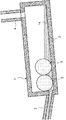
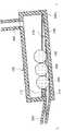
- FIG. 1 is a cross-sectional view showing the cooling device of this embodiment.
- the cooling device includes a heat receiving part 1 having a space for holding the liquid phase refrigerant therein, a liquid phase pipe 3 for supplying the liquid phase refrigerant 2 to the heat receiving part 1, and a gas phase pipe for discharging the gas phase refrigerant from the heat receiving part 1. 4 and a spacer 5 arranged inside the heat receiving portion 1.
- the spacer 5 has a larger specific gravity than the liquid-phase refrigerant 2.
- the spacer 5 can move freely inside the heat receiver 1.
- the spacer 5 has a spherical shape, but may have another shape such as an ellipsoid or a polyhedron.
- the liquid phase refrigerant 2 boils in the boiling part 1a which is the bottom surface inside the heat receiving part, and is discharged from the gas phase pipe 4. At this time, the heat of vaporization of the liquid phase refrigerant 2 is consumed and the heat receiving section 1 is cooled.
- FIG. 2 is a cross-sectional view showing a state where the cooling device 1 is tilted.
- the spacer 5 moves to the lower side of the heat receiver 1.
- the spacer 5 since the spacer 5 has a larger specific gravity than the liquid-phase refrigerant 2, it gathers on the bottom surface of the heat receiver 1 on the lower side.
- the spacer 5 spreads the liquid-phase refrigerant 2 to the higher side of the heat receiver 1 by the excluded volume. Due to this spread, the liquid-phase refrigerant 2 reaches the high side of the heat receiver 1, and the cooling of the boiling portion 1a can be made less likely to be biased.
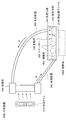
- FIG. 3 is a schematic side view showing the cooling device 1000 of the second embodiment.
- the cooling device 1000 includes a heat receiving unit 100, a liquid phase pipe 300, a gas phase pipe 400, and a heat radiating unit 600, and these are combined to form a closed flow path.
- the closed flow passage is filled with a refrigerant that cools by causing a phase change from a liquid phase to a vapor phase by the heat received by the heat receiving section 100.
- a spacer 500 a part of which is immersed in the liquid-phase refrigerant 200, is arranged inside the heat receiving portion 100.
- heat conduction is performed between the heating element 2000 and the heat receiving portion 100.
- the grease 2100 is arranged to enhance the thermal conductivity between them.
- the heating element 2000 can be an electronic component such as a CPU (Central Processing Unit), but is not limited thereto and is generally applicable to a heating element.
- CPU Central Processing Unit
- the liquid phase refrigerant 200 is supplied to the heat receiving unit 100 from the liquid phase pipe 300 by utilizing the effect of gravity.
- the heat from the heat-generating body 2000 that has been thermally conducted causes the liquid-phase refrigerant 200 inside to boil, thereby changing the phase of the liquid-phase refrigerant 200 into a gas-phase refrigerant 210.
- the liquid-phase refrigerant 200 undergoes a phase change to the gas-phase refrigerant 210, heat is absorbed as latent heat in the refrigerant.
- the density of the gas-phase refrigerant 210 is smaller than that of the liquid-phase refrigerant 200, the gas-phase refrigerant 210 rises due to its buoyancy and moves to the heat radiating section 600 through the gas-phase pipe 400 as indicated by arrow A. Since the vapor phase refrigerant 210 is moved to the heat radiating unit 600 by using buoyancy, the heat radiating unit 600 needs to be vertically above the heat receiving unit 100.
- the heat radiating unit 600 uses a cooler such as a cooling fan 610 to promote heat radiation from the heat radiating unit 600 to the air.
- the vapor-phase refrigerant 210 that has moved to the heat radiating section 600 radiates its heat into the air by the cooling air sent from the cooling fan 610, and changes its phase to the liquid-phase refrigerant 200. Since the liquid-phase refrigerant 200 has a higher density than the gas-phase refrigerant 210, the liquid-phase refrigerant 200 descends due to its gravity, passes through the liquid-phase pipe 300, and is recirculated to the heat receiving section 100 as indicated by an arrow B. The refluxed liquid-phase refrigerant 200 receives heat from the heating element 2000 and is reused for circulation of the refrigerant.
- the cooling device 1000 can circulate the liquid phase refrigerant 200 and the gas phase refrigerant 210 without using a pump by utilizing the phase change of the refrigerant.
- the amount of heat that can be transported by a phase change per unit mass is several hundred times larger than that of the method that transports heat by increasing the temperature of a refrigerant such as water cooling, so it is suitable for heat transport/cooling with high calorific value. There is.
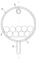
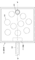
- FIG. 4 is a plan view showing the heat receiving unit 100 in the horizontal state.
- a plurality of spacers 500 are enclosed inside the heat receiving portion 100.
- each spacer 500 has a random position.
- the spacer 500 has a spherical shape.
- the internal space of the heat receiving portion 100 has a cylindrical shape.
- the projection 110 is shaped so as to be connected to the arc by a straight line when viewed from the top. By doing so, it is possible to increase the volume of the spacer 500 immersed in the liquid-phase refrigerant 200 when the heat receiving unit 100 is inclined.
- the shape of the heat receiving portion 100 and the protrusion 110 is not limited to this.
- the shapes of the heat receiving portion 100 and the protrusion 110 can be any shapes as long as they do not hinder the movement of the spacer 500 when the inclination changes.
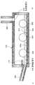
- FIG. 5 is a sectional view showing a section taken along the line KK' of FIG.
- the liquid phase pipe 300 is connected to one side surface of the heat receiving unit 100, and the liquid phase refrigerant 200 flows into the heat receiving unit 100 from the liquid phase pipe port 310 of the connection unit.
- a protrusion 110 is provided on the inner wall of the heat receiving unit 100 above the liquid phase piping port 310. The protrusion 110 restricts the movement of the spacer 500 so that the spacer 500 does not block the liquid phase piping port 310.
- the vapor phase pipe 400 is connected to the upper portion of the heat receiving unit 100 via the vapor phase pipe port 410.
- the liquid phase refrigerant 200 and the spacer 500 are held inside the heat receiving unit 100.
- the specific gravity of the spacer 500 is sufficiently larger than that of the liquid-phase refrigerant 200 and does not float on the liquid-phase refrigerant 200.
- the spacer 500 is spherical, and the cross-sectional area becomes smaller as it gets farther from the center. Therefore, the amount of the liquid-phase refrigerant 200 present varies depending on the height.
- the existing amount of the liquid-phase refrigerant 200 is the smallest at the liquid surface and the largest in the boiling portion 100a farthest from the center. Since the liquid-phase refrigerant 200 undergoes a phase change to the vapor-phase refrigerant 210 in the boiling section 100a, the large amount of refrigerant existing in the boiling section 100a enables efficient use of the refrigerant.
- FIG. 6 is a plan view showing a state in which the heat receiving section 100 is inclined so that the side of the liquid phase pipe 300 becomes lower.
- this state is referred to as tilting to the lower left.
- the spacers 500 gather toward the protrusions 110.
- FIG. 7 is a sectional view taken along line LL′ of FIG.
- the heat receiving unit 100 tilts to the lower left
- the liquid phase refrigerant 200 moves to the lower left due to gravity.
- the spacer 500 also moves to the lower left.
- the liquid level on the liquid phase piping port 310 side rises. This rise of the liquid level is caused not only by the movement of the liquid-phase refrigerant 200 due to the inclination but also by the increase in the volume of the spacer 500 immersed in the liquid-phase refrigerant.
- FIG. 7 shows an example in which the spacers 500 are arranged linearly along the cutting line for the sake of easy understanding of the drawing, but the arrangement of the spacers 500 is not limited to this.
- the number of spacers 500 is preferably such that the area occupied by the spacers 500 is within a range of 1 ⁇ 4 to 1 ⁇ 2 of the area of the bottom surface of the heat receiving part 100 when viewed from above the heat receiving part 100. Further, it is desirable that the size of the spacer 500 is such that about 1/3 of its own volume is immersed in the liquid phase refrigerant 200 when the heat receiving part 100 is in a horizontal state. This is to increase the volume difference in which the spacer 500 is immersed in the liquid phase refrigerant 200 between the horizontal state shown in FIG. 5 and the inclined state shown in FIG.
- FIG. 8 is a cross-sectional view showing a heat receiving portion without the spacer 500.
- the liquid-phase refrigerant 200 does not turn to the boiling portion 100a inclined upward, but the boiling portion 100a is exposed to the space inside the heat receiving portion 100. Since cooling is not performed in this portion, the efficiency of cooling the heating element is reduced.
- FIG. 9 is a cross-sectional view showing a state in which the heat receiving section 100 is inclined in a direction in which the liquid phase piping port 310 side becomes higher.
- a tilted state is also referred to as tilting to the lower right.
- the increase in the volume of the spacer 500 that sinks into the liquid-phase refrigerant 200 is the same as when the spacer 500 is tilted to the lower left. Therefore, it is possible to change the phase of the liquid-phase refrigerant 200 to the vapor-phase refrigerant 210 on the entire surface of the boiling part 100a. As a result, as in the case of leaning to the lower left, even in the state of leaning to the lower right, a stable cooling state can be maintained with a smaller amount of the liquid-phase refrigerant 200.
- FIG. 10 is a cross-sectional view depicting the vicinity of the liquid phase piping port 310 when tilted as described above.
- a dotted line C on the spacer 500 is the position of the liquid surface of the liquid-phase refrigerant 200 in the horizontal state.
- the liquid surface of the liquid-phase refrigerant 200 in the tilted state is at the position indicated by the dotted line D.
- the space in which the spacer 500 is immersed in the liquid-phase refrigerant 200 increases by the amount corresponding to the difference in the liquid level of the liquid-phase refrigerant 200 indicated by the double-headed arrow E, and the liquid-phase refrigerant 200 corresponding to this volume increase is pushed away.
- the liquid level of the liquid-phase refrigerant 200 is rising. Since the liquid level of the liquid-phase refrigerant 200 rises, the right side of the boiling portion 100a can be kept immersed in the liquid-phase refrigerant 200 even with a smaller amount of the liquid-phase refrigerant 200, and even on the right side of the boiling portion 100a. Phase change cooling can be performed. As a result of the above operation, a stable cooling state can be maintained even with a small amount of the liquid-phase refrigerant 200.
- the protrusion 110 will be described.
- the height of the protrusion 110 is indicated by a double-headed arrow F. Since the protrusion 110 needs to contact the spacer 500 promptly, F can be set to be approximately the same as the radius of the spacer 500, for example. However, when the protrusion 110 affects the movement of the refrigerant 200, the protrusion 110 may be installed at a higher position. Further, the size of the protrusion 110 is such that the liquid phase piping port 310 and the spacer 500 maintain a sufficient distance when they come into contact with the spacer 500 and do not hinder the inflow of the liquid phase refrigerant 200. With such a configuration, the protrusion 110 restricts the movement of the spacer 500, and the spacer 500 does not prevent the inflow of the liquid-phase refrigerant 200.
- cooling can be performed uniformly.
- FIG. 11 is a top view which shows the heat receiving part 101 of 3rd Embodiment.
- FIG. 12 is a sectional view taken along line MM′ of FIG.
- a plurality of spherical spacers 500 similar to those of the second embodiment are enclosed inside the heat receiving portion 101.
- the internal space of the heat receiving section 100 has a quadrangular prism shape.
- the protrusion 111 has a rectangular shape when viewed from above.
- the internal space of the heat receiving portion 101 is a quadrangular prism, but it may be a polygonal prism other than the quadrangular prism.
- the spacer 500 moves to the liquid phase pipe 300 side and the liquid level rises, as in the second embodiment.
- the liquid-phase refrigerant 200 spreads to the boiling portion 101a inclined to the higher side.
- the protrusion 111 restricts the movement of the spacer 500, so that the liquid-phase refrigerant 200 is smoothly supplied from the liquid-phase piping port 311 to the inside of the heat receiving portion 101.
- the spacer has a spherical shape
- any shape other than a spherical shape may be used as long as it can smoothly move along the boiling portion inside the heat receiving portion. ..
- it may be a columnar spacer 501 as shown in FIG. 13A, or a polyhedral spacer 502 as shown in FIG. 13B.
Landscapes
- Engineering & Computer Science (AREA)
- Physics & Mathematics (AREA)
- Thermal Sciences (AREA)
- Mechanical Engineering (AREA)
- General Engineering & Computer Science (AREA)
- Life Sciences & Earth Sciences (AREA)
- Sustainable Development (AREA)
- Cooling Or The Like Of Electrical Apparatus (AREA)
- Cooling Or The Like Of Semiconductors Or Solid State Devices (AREA)
Abstract
冷却装置は、内部に空間を有する受熱部と、受熱部に液相冷媒を供給する液相配管と、受熱部から気相冷媒を排出する気相配管と、受熱部の内部に配置されたスペーサーとを有する。スペーサーは、液相冷媒より大きな比重を持っている。また、スペーサーは、受熱器の底面に沿って移動できる形状を有している。受熱部が傾くと、スペーサーが受熱器の低い側に移動する。ここで、スペーサーは、液相冷媒2より比重が大きいため、受熱器の低い側の底面に集まる。そしてスペーサーによって、排除された体積分だけ、液相冷媒が、受熱器の高い側に広がり、均一性の高い冷却を行うことができる。
Description
本発明は、冷却装置および冷却装置の製造方法に関する。
近年の高性能・高微細化が進んだ半導体や電子機器で大量の熱が発生するようになっている。これらの機器等の、故障を防ぎ安定した動作を行うためには、この大量の熱を速やかに冷却する必要がある。この高発熱密度の電子部品を冷却する手段として、冷媒の相変化を利用して、熱を輸送、拡散、冷却する冷却装置(以下、「相変化冷却装置」と呼ぶ)が考えられている。
一般的な相変化冷却装置は、CPUなどの電子部品から成る発熱体の熱を受ける受熱部と、冷媒の相変化を利用して輸送された熱を放熱する放熱部と、それらをつなぐ配管によって構成されている。受熱部には、液管から液相冷媒が供給され、発熱体から受ける熱によって、液相冷媒が沸騰し気相冷媒となる。この時、蒸発熱に相当する熱が吸収され、受熱部が冷却される。発生した気相冷媒は、気相管から排出されて、放熱部に移動し、放熱部で熱を放出して液化する。液化した液相冷媒は、液管に戻り、再び、受熱部に供給される。このような動作により、相変化冷却装置では、ポンプを使わずに冷媒を循環して、受熱部を冷却することができる。
上記のような相変化冷却装置の一例が、例えば特許文献1に開示されている。特許文献1の冷却装置は、電子部品等に密着する受熱部を備えた蒸発器と、蒸発器に作動液(冷媒)を供給する液管と、蒸発器で発生した冷媒蒸気を排出する蒸気管と、蒸発器内の空間を液管側と蒸気管側とに隔てる、板状で多孔質のウィックとを備えている。液管から蒸発器内に流入した冷媒は、毛細管現象によりウィックの厚み方向に移動し、電子部品等から受け取った熱により蒸発する。この時、蒸発熱に相当する熱が吸収され、受熱部が冷却される。この冷却装置では、ウィックを板状にすることで、蒸発器を薄型化している。
しかし、特許文献1のような一般的な冷却装置では、冷却装置が傾くと、受熱部を均一に冷却できなくなるという問題がある。冷却装置が傾くと、液相冷媒は低い側に偏り、高い側には供給されなくなる。その結果、傾いた冷却装置の、高い側では冷却が十分に行われなくなり、冷却装置の冷却効率が低下する。
本発明は、上記の問題点に鑑みてなされたものであり、冷却装置の傾きによる冷却効率の低下を低減できる冷却装置を提供することを目的としている。
上記の課題を解決するため、冷却装置は、内部に空間を有する受熱部と、受熱部に液相冷媒を供給する液相配管と、受熱部から気相冷媒を排出する気相配管と、受熱部の内部に配置されたスペーサーとを有する。スペーサーは、液相冷媒より大きな比重を持っている。また、スペーサーは、受熱器の底面に沿って移動できる形状を有している。受熱部が傾くと、スペーサーが受熱器の低い側に移動する。ここで、スペーサーは、液相冷媒2より比重が大きいため、受熱器の低い側の底面に集まる。そしてスペーサーによって、排除された体積分だけ、液相冷媒が、受熱器の高い側に広がり、均一性の高い冷却を行うことができる。
本発明の効果は、冷却装置の傾きによる冷却効率の低下を低減できる冷却装置を提供できることである。
以下、図面を参照しながら、本発明の実施形態を詳細に説明する。但し、以下に述べる実施形態には、本発明を実施するために技術的に好ましい限定がされているが、発明の範囲を以下に限定するものではない。なお各図面の同様の構成要素には同じ番号を付し、説明を省略する場合がある。
(第1の実施形態)
図1は、本実施形態の冷却装置を示す断面図である。冷却装置は、内部に液相冷媒を保持する空間を有する受熱部1と、受熱部1に液相冷媒2を供給する液相配管3と、受熱部1から気相冷媒を排出する気相配管4と、受熱部1の内部に配置されたスペーサー5とを有する。スペーサー5は、液相冷媒2より大きな比重を持っている。スペーサー5は、受熱器1の内部で自由に動けるようになっている。図1の例では、スペーサー5は球形であるが、楕円体や多面体など他の形状であっても良い。
図1は、本実施形態の冷却装置を示す断面図である。冷却装置は、内部に液相冷媒を保持する空間を有する受熱部1と、受熱部1に液相冷媒2を供給する液相配管3と、受熱部1から気相冷媒を排出する気相配管4と、受熱部1の内部に配置されたスペーサー5とを有する。スペーサー5は、液相冷媒2より大きな比重を持っている。スペーサー5は、受熱器1の内部で自由に動けるようになっている。図1の例では、スペーサー5は球形であるが、楕円体や多面体など他の形状であっても良い。
受熱部1が、熱を受け取ると、受熱部内部の底面に当たる沸騰部1aで、液相冷媒2が沸騰し、気相配管4から排出される。この時、液相冷媒2の蒸発熱が消費され、受熱部1が冷却される。
図2は、冷却装置1が傾いた状態を示す断面図である。冷却装置1が傾くとスペーサー5が受熱器1の低い側に移動する。ここで、スペーサー5は、液相冷媒2より比重が大きいため、受熱器1の低い側の底面に集まる。そしてスペーサー5によって、排除された体積分だけ、液相冷媒2が、受熱器1の高い側に広がる。この広がりにより、受熱器1の高い側まで、液相冷媒2が到達し、沸騰部1aの冷却に偏りが生じ難くすることができる。
以上説明したように、本実施形態によれば、冷却装置の傾いた場合の冷却効率の低下を低減することができる。
(第2の実施形態)
図3は、第2の実施形態の冷却装置1000を示す側面模式図である。冷却装置1000は、受熱部100と、液相配管300と、気相配管400と、放熱部600とを有し、これらが結合して閉鎖流路を形成している。この閉鎖流路には受熱部100で受け取った熱により、液相から気相への相変化を起こすことで冷却を行う、冷媒が封入されている。そして、受熱部100の内部には、液相冷媒200に一部が浸漬されたスペーサー500が配置されている、また、図3の例では、発熱体2000と受熱部100との間に熱伝導グリース2100を配置して、両者の間の熱伝導性を高めている。図3の例では、発熱体2000は、例えば、CPU(Central Processing Unit)などの電子部品とすることができるが、これらに限られるものではなく、発熱するものに一般的に適用できる。
図3は、第2の実施形態の冷却装置1000を示す側面模式図である。冷却装置1000は、受熱部100と、液相配管300と、気相配管400と、放熱部600とを有し、これらが結合して閉鎖流路を形成している。この閉鎖流路には受熱部100で受け取った熱により、液相から気相への相変化を起こすことで冷却を行う、冷媒が封入されている。そして、受熱部100の内部には、液相冷媒200に一部が浸漬されたスペーサー500が配置されている、また、図3の例では、発熱体2000と受熱部100との間に熱伝導グリース2100を配置して、両者の間の熱伝導性を高めている。図3の例では、発熱体2000は、例えば、CPU(Central Processing Unit)などの電子部品とすることができるが、これらに限られるものではなく、発熱するものに一般的に適用できる。
次に冷却と、冷媒の循環の動作について説明する。受熱部100には、重力の作用を利用して、液相配管300から液相冷媒200が供給される。
受熱部100の下面の沸騰部100aでは、熱伝導された発熱体2000からの熱によって、内部の液相冷媒200が沸騰し、液相冷媒200を気相冷媒210に相変化させる。液相冷媒200が気相冷媒210に相変化するとき、熱を潜熱として、冷媒中に吸収する。気相冷媒210は、その密度が液相冷媒200より小さいため、その浮力により上昇し、矢印Aで示されるように気相配管400を通り放熱部600に移動する。浮力を利用して放熱部600に気相冷媒210を移動させるため、放熱部600は受熱部100より鉛直上方にある必要がある。
放熱部600では、冷却ファン610などの冷却器を利用して、放熱部600から空気中への放熱を促進する。放熱部600に移動した気相冷媒210は、例えば、冷却ファン610から送られた冷却風によって、空気中にその熱を放熱し、液相冷媒200に相変化する。液相冷媒200は、気相冷媒210より密度が大きいため、その重力により降下し、液相配管300を通り、矢印Bで示されるように、受熱部100に還流される。還流された液相冷媒200は、発熱体2000から熱を受けることで冷媒の循環に再び利用される。
このように冷却装置1000は、冷媒の相変化を利用することで、ポンプを使わずに液相冷媒200および気相冷媒210を循環させることができる。また単位質量あたりの、相変化によって輸送できる熱量は、水冷などの冷媒の温度上昇によって熱を輸送する方式と比較して、数100倍と大きいため、高発熱量の熱輸送・冷却に適している。
次に本実施形態の受熱部100の構成について説明する。図4は、水平状態にある時の受熱部100を示す平面図である。図4に示すように、受熱部100の内部には、スペーサー500が複数個封入されている。水平状態では、それぞれのスペーサー500は、ランダムな位置を取っている。ここでは、スペーサー500は球形としている。またこの例では、受熱部100の内部空間を円柱状としている。そして、突起110を、上面から見たときに、円弧と直線で結ばれた形状となるようにしている。このようにすることで、受熱部100が傾いた場合に、液相冷媒200に浸漬されるスペーサー500の体積を多くすることができる。なお、これは受熱部100および突起110の形状の一例であって、これに限られるものではない。受熱部100及び突起110の形状は、傾きが変化したときにスペーサー500の移動を阻害しない形状であれば、任意の形状とすることができる。
図5は図4のK-K´における断面を示す断面図である。図5に示すように、受熱部100の一側面には液相配管300が接続され、接続部の液相配管口310から受熱部100に液相冷媒200が流入する。そして、液相配管口310の上方の、受熱部100の内壁には、突起110が設けられている。突起110は、スペーサー500が液相配管口310を閉塞することが無いように、スペーサー500の移動を制限する。また、受熱部100の上部には、気相配管口410を介して、気相配管400が接続されている。
受熱部100の内部には、液相冷媒200と、スペーサー500とが保持されている。スペーサー500の比重は液相冷媒200より十分に大きく、液相冷媒200に浮くことはない。またスペーサー500は球形であり、その中心から離れるほど断面積は小さくなる。このため、液相冷媒200が存在する量は、高さによって異なる。スペーサー500の中心より低い位置にしか液相冷媒200が存在しない場合は、液相冷媒200の存在量は液面で最少となり、中心から最も離れたすなわち沸騰部100aで最多となる。沸騰部100aで、液相冷媒200が気相冷媒210に相変化するため、沸騰部100aに多くの冷媒が存在することで冷媒の効率的な利用ができる。
図6は、受熱部100が液相配管300の側が低くなるように、傾いた状態を示す平面図である。ここではこの状態を、左下に傾いたと称することとする。このように傾くことにより、スペーサー500は突起110に向かって集合する。
図7は、図6のL-L´における断面図である。受熱部100が左下に傾くことにより、液相冷媒200は重力によって、左下へ移動する。この時、スペーサー500も同様に左下へと移動する。こうして、液相配管口310側の液面が上昇する。この液面の上昇は、傾きによる液相冷媒200の移動だけではなく、スペーサー500が液相冷媒に浸る体積増加によっても引き起こされる。すなわち、液相冷媒200に浸るスペーサー500の体積増加分だけ、液相冷媒200が押しのけられることで液相冷媒200の液面が上昇する。その結果、高い方に傾いた気相配管400側の沸騰部100aまで液相冷媒が行き渡り、沸騰部100a全体に渡り相変化冷却を行うことができる。なお、図7では、図を見やすくするために、スペーサー500が切断線に沿って直線的に並んでいる例を示しているが、スペーサー500の配列はこれに限られることはない。
スペーサー500の数量は、受熱部100の上から見た時に、スペーサー500の占める面積が、受熱部100の底面の面積の1/4から1/2の範囲に収まる数量であることが望ましい。またスペーサー500の大きさは、受熱部100が水平状態にある時に、液相冷媒200に自身の体積の1/3程度が浸る程度であることが望ましい。これは図5に示す水平状態にある時と、図7に示す傾いた状態にある時との間で、スペーサー500が液相冷媒200に浸される体積差を大きくするためである。
ここで比較のために、スペーサー500が無い場合について説明する。図8は、スペーサー500が無い受熱部を示した断面図である。この例では、液相冷媒200が高い方に傾いた沸騰部100aに回らず、沸騰部100aが受熱部100の内部の空間に暴露されてしまっている。この部分では、冷却が行われないため、発熱体の冷却の効率が低下する。
次に、液相配管300側が高くなる方向に傾いた場合について説明する。図9は、液相配管口310側が高くなる方向に、受熱部100が傾いた状態を示す断面図である。ここでは、このように傾いた状態を右下に傾くとも呼称することとする。受熱部100が右下へ傾いた状態では、液相冷媒200、スペーサー500ともに、右下へ移動することになる。この時、右側には突起110が無いため、スペーサー500は壁面と接触するまで移動する。液相冷媒200に沈み込むスペーサー500の体積増加は、左下に傾いたときと同様で、液相冷媒200の液面を上昇させ、沸騰部100aの左側にも液相冷媒200が行き渡る。このため、沸騰部100aの全面で、液相冷媒200を気相冷媒210に相変化させることができる。結果として左下に傾いたときと同様に、右下に傾いた状態でも、より少ない液相冷媒200の量で、安定した冷却状態を保つことが出来る。
次に、液相配管300側が低くなる方向に傾いた時の、液面の上昇について説明する。図10は、上記のように傾いた時の、液相配管口310近傍を描いた断面図である。図10の中で、スペーサー500に点線Cで示したのは、水平状態における液相冷媒200の液面の位置である。そして、このように傾いた状態における液相冷媒200の液面は、点線Dで示した位置になっている。すなわち両矢印Eで示される液相冷媒200の液面の差に対応する分だけ、スペーサー500が液相冷媒200に浸る体積が増加し、この体積増加分の液相冷媒200が押しのけられることで、液相冷媒200の液面が上昇している。液相冷媒200の液面が上昇するため、より少ない液相冷媒200の量でも、沸騰部100aの右側が、液相冷媒200に浸された状態を保つことができ、沸騰部100aの右側でも相変化冷却を行うことができる。以上のような動作により、結果として、少ない量の液相冷媒200でも、安定した冷却状態を保つことが出来る。
次に突起110について説明する。図10には、突起110の高さを、両矢印Fで示している。突起110はスペーサー500と速やかに接触する必要があるため、Fは、例えばスペーサー500の半径と同程度とすることができる。ただし、突起110が、冷媒200の移動に影響を与える場合は、これより高い位置に設置してもよい。また、突起110の大きさは、スペーサー500と接触した際に、液相配管口310とスペーサー500とが十分な距離を保ち、液相冷媒200の流入を阻害しないサイズとする。このような構成とすることにより、突起110が、スペーサー500の移動を制限し、スペーサー500が液相冷媒200の流入を妨げることがないようになっている。
以上説明したように、本実施形態によれば、冷却装置の受熱部が傾いても、冷却を均一に行うことができる。
(第3の実施形態)
図11は、第3の実施形態の受熱部101を示す平面図である。また図12は、図11のM-M´における断面図である。図11に示すように、受熱部101の内部には、第2の実施形態と同様の球形のスペーサー500が複数個封入されている。また図11、12に示すように、本実施形態では、受熱部100の内部空間を四角柱状としている。そして、突起111を、上面から見たときに、長方形となるようにしている。なお、この例では、受熱部101の内部空間を四角柱状としたが、四角柱以外の多角柱状であっても良い。
図11は、第3の実施形態の受熱部101を示す平面図である。また図12は、図11のM-M´における断面図である。図11に示すように、受熱部101の内部には、第2の実施形態と同様の球形のスペーサー500が複数個封入されている。また図11、12に示すように、本実施形態では、受熱部100の内部空間を四角柱状としている。そして、突起111を、上面から見たときに、長方形となるようにしている。なお、この例では、受熱部101の内部空間を四角柱状としたが、四角柱以外の多角柱状であっても良い。
図12に示すように、受熱部101が、液相配管300側が低くなるように傾くと、第2の実施形態と同様に、スペーサー500が液相配管300側に移動して液面が上昇し、高い方に傾いた沸騰部101aまで、液相冷媒200が行き渡る。そして、突起111がスペーサー500の移動を制限することにより、液相冷媒200は、液相配管口311から受熱部101の内部にスムーズに供給される。
以上のような動作により、沸騰部の全面で均一性が良い相変化冷却を行うことができる。
(第4の実施形態)
第1から第3の実施形態では、スペーサーが球形である例を用いて説明したが、受熱部内部の沸騰部に沿ってスムーズに移動できる形状であれば、球形以外の形状であっても良い。例えば、図13(a)に示すように円柱状のスペーサー501であっても良いし、図13(b)に示すように多面体のスペーサー502であっても良い。
第1から第3の実施形態では、スペーサーが球形である例を用いて説明したが、受熱部内部の沸騰部に沿ってスムーズに移動できる形状であれば、球形以外の形状であっても良い。例えば、図13(a)に示すように円柱状のスペーサー501であっても良いし、図13(b)に示すように多面体のスペーサー502であっても良い。
以上説明したように、本実施形態によっても、第2、第3の実施形態と同様に、受熱部が均一な冷却を行うために利用できるスペーサーを構成することができる。
以上、上述した実施形態を模範的な例として本発明を説明した。しかしながら、本発明は、上記実施形態には限定されない。即ち、本発明は、本発明のスコープ内において、当業者が理解し得る様々な態様を適用することができる。
この出願は、2018年12月26日に出願された日本出願特願2018-242159を基礎とする優先権を主張し、その開示の全てをここに取り込む。
1、100 受熱部
2、200 液相冷媒
3、300 液相配管
4、400 気相配管
5、500、501、502 スペーサー
110 突起
210 気相冷媒
310 液相配管口
410 気相配管口
1000 冷却装置
2000 発熱体
2、200 液相冷媒
3、300 液相配管
4、400 気相配管
5、500、501、502 スペーサー
110 突起
210 気相冷媒
310 液相配管口
410 気相配管口
1000 冷却装置
2000 発熱体
Claims (10)
- 内部に冷媒を保持する空間を有する受熱部と、
前記受熱部に液相冷媒を供給する液相配管と、
前記受熱部から気相冷媒を排出する気相配管と、
前記受熱部の内部に配置されたスペーサーと
を有し、
前記スペーサーは、
前記液相冷媒より比重が大きく、
前記受熱部が傾いた場合に、前記受熱部の内側底面に沿って下方に移動し、前記液相冷媒の液面を押し上げる形状を有する
ことを特徴とする冷却装置。 - 前記気相配管から回収した前記気相冷媒を冷却して液化し、液化した前記液相冷媒を前記液相配管に送出する放熱部を有し、閉鎖流路を形成している
ことを特徴とする請求項1に記載の冷却装置。 - 前記スペーサーが、前記液相配管と前記受熱部との接続部に設けられた液相冷媒供給口を閉塞することを、妨げるように、前記スペーサーの移動を制限する突起を前記液相冷媒供給口の近傍に備えている
ことを特徴とする請求項1または2のいずれか一項に記載の冷却装置。 - 前記突起が、前記受熱部の内部の底面から前記スペーサーの外形の1/2倍以上1倍未満の高さに設けられている
ことを特徴とする請求項3に記載の冷却装置。 - 前記受熱部の内部空間が円柱状である
ことを特徴とする請求項1乃至4のいずれか一項に記載の冷却装置。 - 前記スペーサーが球形である
ことを特徴とする請求項1乃至5のいずれか一項に記載の冷却装置。 - 前記スペーサーが多面体である
ことを特徴とする請求項1乃至5のいずれか一項に記載の冷却装置。 - 前記受熱部を上から見た時に、
前記スペーサーの占める面積の合計が、前記受熱部の内部の底面積の1/4以上1/2未満である
ことを特徴とする請求項1乃至7のいずれか一項に記載の冷却装置。 - 内部に冷媒を保持する空間を有する受熱部と、
前記受熱部に液相冷媒を供給する液相配管と、
前記受熱部から気相冷媒を排出する気相配管と、
前記気相配管から回収した前記気相冷媒を冷却して液化し、液化した前記液相冷媒を前記液相配管に送出する放熱部と
を用いて閉鎖流路を形成し、
前記受熱部の内部に、
前記液相冷媒より比重が大きく、前記受熱部が傾いた場合に、前記受熱部の内側底面に沿って下方に移動し、前記液相冷媒の液面を押し上げる形状を有するスペーサーを配置する
ことを特徴とする冷却装置の製造方法。 - 前記スペーサーが球形である
ことを特徴とする請求項9に記載の冷却装置の製造方法。
Priority Applications (1)
| Application Number | Priority Date | Filing Date | Title |
|---|---|---|---|
| US17/312,461 US11740035B2 (en) | 2018-12-26 | 2019-12-19 | Cooling device and manufacturing method for cooling devices |
Applications Claiming Priority (2)
| Application Number | Priority Date | Filing Date | Title |
|---|---|---|---|
| JP2018242159A JP6787988B2 (ja) | 2018-12-26 | 2018-12-26 | 冷却装置および冷却装置の製造方法 |
| JP2018-242159 | 2018-12-26 |
Publications (1)
| Publication Number | Publication Date |
|---|---|
| WO2020137822A1 true WO2020137822A1 (ja) | 2020-07-02 |
Family
ID=71128615
Family Applications (1)
| Application Number | Title | Priority Date | Filing Date |
|---|---|---|---|
| PCT/JP2019/049878 Ceased WO2020137822A1 (ja) | 2018-12-26 | 2019-12-19 | 冷却装置および冷却装置の製造方法 |
Country Status (3)
| Country | Link |
|---|---|
| US (1) | US11740035B2 (ja) |
| JP (1) | JP6787988B2 (ja) |
| WO (1) | WO2020137822A1 (ja) |
Citations (7)
| Publication number | Priority date | Publication date | Assignee | Title |
|---|---|---|---|---|
| JP2005321152A (ja) * | 2004-05-10 | 2005-11-17 | Matsushita Electric Ind Co Ltd | 熱移動装置及びそれを用いた冷却装置 |
| JP2009088125A (ja) * | 2007-09-28 | 2009-04-23 | Panasonic Corp | 冷却装置およびそれを備えた電子機器 |
| WO2010058520A1 (ja) * | 2008-11-18 | 2010-05-27 | 日本電気株式会社 | 沸騰冷却装置 |
| WO2011040129A1 (ja) * | 2009-09-29 | 2011-04-07 | 日本電気株式会社 | 電子機器装置の熱輸送構造 |
| KR101305437B1 (ko) * | 2012-03-22 | 2013-09-26 | 주식회사 루티마라이트 | 냉각 모듈 및 그를 포함하는 조명장치 |
| WO2018047529A1 (ja) * | 2016-09-09 | 2018-03-15 | 株式会社デンソー | 機器温調装置 |
| JP2018115858A (ja) * | 2012-09-19 | 2018-07-26 | 日本電気株式会社 | 冷却装置、それに使用される受熱部、沸騰部、その製造方法 |
Family Cites Families (2)
| Publication number | Priority date | Publication date | Assignee | Title |
|---|---|---|---|---|
| US9074825B2 (en) * | 2007-09-28 | 2015-07-07 | Panasonic Intellectual Property Management Co., Ltd. | Heatsink apparatus and electronic device having the same |
| JP5765045B2 (ja) | 2011-04-28 | 2015-08-19 | 富士通株式会社 | ループ型ヒートパイプ及びその製造方法 |
-
2018
- 2018-12-26 JP JP2018242159A patent/JP6787988B2/ja active Active
-
2019
- 2019-12-19 US US17/312,461 patent/US11740035B2/en active Active
- 2019-12-19 WO PCT/JP2019/049878 patent/WO2020137822A1/ja not_active Ceased
Patent Citations (7)
| Publication number | Priority date | Publication date | Assignee | Title |
|---|---|---|---|---|
| JP2005321152A (ja) * | 2004-05-10 | 2005-11-17 | Matsushita Electric Ind Co Ltd | 熱移動装置及びそれを用いた冷却装置 |
| JP2009088125A (ja) * | 2007-09-28 | 2009-04-23 | Panasonic Corp | 冷却装置およびそれを備えた電子機器 |
| WO2010058520A1 (ja) * | 2008-11-18 | 2010-05-27 | 日本電気株式会社 | 沸騰冷却装置 |
| WO2011040129A1 (ja) * | 2009-09-29 | 2011-04-07 | 日本電気株式会社 | 電子機器装置の熱輸送構造 |
| KR101305437B1 (ko) * | 2012-03-22 | 2013-09-26 | 주식회사 루티마라이트 | 냉각 모듈 및 그를 포함하는 조명장치 |
| JP2018115858A (ja) * | 2012-09-19 | 2018-07-26 | 日本電気株式会社 | 冷却装置、それに使用される受熱部、沸騰部、その製造方法 |
| WO2018047529A1 (ja) * | 2016-09-09 | 2018-03-15 | 株式会社デンソー | 機器温調装置 |
Also Published As
| Publication number | Publication date |
|---|---|
| JP2020106156A (ja) | 2020-07-09 |
| US11740035B2 (en) | 2023-08-29 |
| JP6787988B2 (ja) | 2020-11-18 |
| US20220057149A1 (en) | 2022-02-24 |
Similar Documents
| Publication | Publication Date | Title |
|---|---|---|
| JP7295381B2 (ja) | 冷却装置、冷却システム及び冷却方法 | |
| JP5757086B2 (ja) | 冷却構造及び電子機器並びに冷却方法 | |
| JP6015675B2 (ja) | 冷却装置及びそれを用いた電子機器 | |
| CN214582684U (zh) | 冷却装置及使用冷却装置的冷却系统 | |
| US20120120604A1 (en) | Heat dissipation device | |
| JP6604330B2 (ja) | 冷媒中継装置、それを用いた冷却装置、および冷却方法 | |
| JP2008281229A (ja) | 蒸発器およびこれを用いた循環型冷却装置 | |
| JPWO2012059975A1 (ja) | ループ型ヒートパイプ及びこれを用いた電子機器 | |
| JP2009088125A (ja) | 冷却装置およびそれを備えた電子機器 | |
| WO2015146110A1 (ja) | 相変化冷却器および相変化冷却方法 | |
| JP2012247166A (ja) | ヒートパイプ | |
| JP2013007501A (ja) | 冷却装置 | |
| JP5874935B2 (ja) | 平板型冷却装置及びその使用方法 | |
| JP2017083050A (ja) | 冷却装置およびこれを搭載した電子機器 | |
| Mohammed et al. | Performance improvements of air-cooled thermal tool with advanced technologies | |
| JP6787988B2 (ja) | 冷却装置および冷却装置の製造方法 | |
| WO2016051569A1 (ja) | 蒸発器、冷却装置及び電子装置 | |
| JP2017166710A (ja) | 冷却装置およびこれを搭載した電子機器 | |
| JP6024665B2 (ja) | 平板型冷却装置及びその使用方法 | |
| US20070295488A1 (en) | Thermosyphon for operation in multiple orientations relative to gravity | |
| JP7399742B2 (ja) | 冷却装置 | |
| JP2017041577A (ja) | 冷却装置および冷却方法 | |
| WO2020054752A1 (ja) | 冷却装置および冷却装置を用いた冷却システム | |
| JP7683258B2 (ja) | 沸騰冷却装置、および発熱体の冷却方法 | |
| JP2024008426A (ja) | 沸騰冷却装置 |
Legal Events
| Date | Code | Title | Description |
|---|---|---|---|
| 121 | Ep: the epo has been informed by wipo that ep was designated in this application |
Ref document number: 19906102 Country of ref document: EP Kind code of ref document: A1 |
|
| NENP | Non-entry into the national phase |
Ref country code: DE |
|
| 122 | Ep: pct application non-entry in european phase |
Ref document number: 19906102 Country of ref document: EP Kind code of ref document: A1 |