WO2020137768A1 - 冷凍サイクル装置および流量調整機構 - Google Patents
冷凍サイクル装置および流量調整機構 Download PDFInfo
- Publication number
- WO2020137768A1 WO2020137768A1 PCT/JP2019/049728 JP2019049728W WO2020137768A1 WO 2020137768 A1 WO2020137768 A1 WO 2020137768A1 JP 2019049728 W JP2019049728 W JP 2019049728W WO 2020137768 A1 WO2020137768 A1 WO 2020137768A1
- Authority
- WO
- WIPO (PCT)
- Prior art keywords
- temperature
- heat medium
- radiator
- air
- temperature heat
- Prior art date
Links
Images


Classifications
-
- B—PERFORMING OPERATIONS; TRANSPORTING
- B60—VEHICLES IN GENERAL
- B60H—ARRANGEMENTS OF HEATING, COOLING, VENTILATING OR OTHER AIR-TREATING DEVICES SPECIALLY ADAPTED FOR PASSENGER OR GOODS SPACES OF VEHICLES
- B60H1/00—Heating, cooling or ventilating [HVAC] devices
- B60H1/22—Heating, cooling or ventilating [HVAC] devices the heat being derived otherwise than from the propulsion plant
-
- B—PERFORMING OPERATIONS; TRANSPORTING
- B60—VEHICLES IN GENERAL
- B60H—ARRANGEMENTS OF HEATING, COOLING, VENTILATING OR OTHER AIR-TREATING DEVICES SPECIALLY ADAPTED FOR PASSENGER OR GOODS SPACES OF VEHICLES
- B60H1/00—Heating, cooling or ventilating [HVAC] devices
- B60H1/00271—HVAC devices specially adapted for particular vehicle parts or components and being connected to the vehicle HVAC unit
- B60H1/00278—HVAC devices specially adapted for particular vehicle parts or components and being connected to the vehicle HVAC unit for the battery
-
- B—PERFORMING OPERATIONS; TRANSPORTING
- B60—VEHICLES IN GENERAL
- B60H—ARRANGEMENTS OF HEATING, COOLING, VENTILATING OR OTHER AIR-TREATING DEVICES SPECIALLY ADAPTED FOR PASSENGER OR GOODS SPACES OF VEHICLES
- B60H1/00—Heating, cooling or ventilating [HVAC] devices
- B60H1/00485—Valves for air-conditioning devices, e.g. thermostatic valves
-
- B—PERFORMING OPERATIONS; TRANSPORTING
- B60—VEHICLES IN GENERAL
- B60H—ARRANGEMENTS OF HEATING, COOLING, VENTILATING OR OTHER AIR-TREATING DEVICES SPECIALLY ADAPTED FOR PASSENGER OR GOODS SPACES OF VEHICLES
- B60H1/00—Heating, cooling or ventilating [HVAC] devices
- B60H1/00642—Control systems or circuits; Control members or indication devices for heating, cooling or ventilating devices
- B60H1/00814—Control systems or circuits characterised by their output, for controlling particular components of the heating, cooling or ventilating installation
- B60H1/00878—Control systems or circuits characterised by their output, for controlling particular components of the heating, cooling or ventilating installation the components being temperature regulating devices
- B60H1/00899—Controlling the flow of liquid in a heat pump system
-
- B—PERFORMING OPERATIONS; TRANSPORTING
- B60—VEHICLES IN GENERAL
- B60H—ARRANGEMENTS OF HEATING, COOLING, VENTILATING OR OTHER AIR-TREATING DEVICES SPECIALLY ADAPTED FOR PASSENGER OR GOODS SPACES OF VEHICLES
- B60H1/00—Heating, cooling or ventilating [HVAC] devices
- B60H1/32—Cooling devices
- B60H1/3204—Cooling devices using compression
- B60H1/3228—Cooling devices using compression characterised by refrigerant circuit configurations
- B60H1/32284—Cooling devices using compression characterised by refrigerant circuit configurations comprising two or more secondary circuits, e.g. at evaporator and condenser side
-
- B—PERFORMING OPERATIONS; TRANSPORTING
- B60—VEHICLES IN GENERAL
- B60H—ARRANGEMENTS OF HEATING, COOLING, VENTILATING OR OTHER AIR-TREATING DEVICES SPECIALLY ADAPTED FOR PASSENGER OR GOODS SPACES OF VEHICLES
- B60H1/00—Heating, cooling or ventilating [HVAC] devices
- B60H1/00271—HVAC devices specially adapted for particular vehicle parts or components and being connected to the vehicle HVAC unit
- B60H2001/00307—Component temperature regulation using a liquid flow
-
- B—PERFORMING OPERATIONS; TRANSPORTING
- B60—VEHICLES IN GENERAL
- B60H—ARRANGEMENTS OF HEATING, COOLING, VENTILATING OR OTHER AIR-TREATING DEVICES SPECIALLY ADAPTED FOR PASSENGER OR GOODS SPACES OF VEHICLES
- B60H1/00—Heating, cooling or ventilating [HVAC] devices
- B60H1/00642—Control systems or circuits; Control members or indication devices for heating, cooling or ventilating devices
- B60H1/00814—Control systems or circuits characterised by their output, for controlling particular components of the heating, cooling or ventilating installation
- B60H1/00878—Control systems or circuits characterised by their output, for controlling particular components of the heating, cooling or ventilating installation the components being temperature regulating devices
- B60H2001/00928—Control systems or circuits characterised by their output, for controlling particular components of the heating, cooling or ventilating installation the components being temperature regulating devices comprising a secondary circuit
-
- B—PERFORMING OPERATIONS; TRANSPORTING
- B60—VEHICLES IN GENERAL
- B60H—ARRANGEMENTS OF HEATING, COOLING, VENTILATING OR OTHER AIR-TREATING DEVICES SPECIALLY ADAPTED FOR PASSENGER OR GOODS SPACES OF VEHICLES
- B60H1/00—Heating, cooling or ventilating [HVAC] devices
- B60H1/00642—Control systems or circuits; Control members or indication devices for heating, cooling or ventilating devices
- B60H1/00814—Control systems or circuits characterised by their output, for controlling particular components of the heating, cooling or ventilating installation
- B60H1/00878—Control systems or circuits characterised by their output, for controlling particular components of the heating, cooling or ventilating installation the components being temperature regulating devices
- B60H2001/00949—Control systems or circuits characterised by their output, for controlling particular components of the heating, cooling or ventilating installation the components being temperature regulating devices comprising additional heating/cooling sources, e.g. second evaporator
Definitions
- the present disclosure relates to a vapor compression refrigeration cycle device and a flow rate adjustment mechanism used for the same.
- Patent Document 1 describes a heat management device for a vehicle in which a cooling liquid heated by a condenser of a refrigeration cycle flows between a heater core and a radiator.
- the heater core heats the air by exchanging heat between the air blown into the passenger compartment and the cooling liquid.
- the radiator cools the coolant by exchanging heat between the coolant and the air outside the vehicle compartment.
- the air outside the vehicle compartment is referred to as outside air.
- an electric device such as an inverter is cooled by the cooling liquid cooled by the first evaporator of the refrigeration cycle, and the air blown into the vehicle compartment is cooled by the second evaporator of the refrigeration cycle.
- the heat absorbed by the refrigerant in the first evaporator and the second evaporator and the heat generated by the compressor in the refrigeration cycle are given from the refrigerant to the cooling liquid by the condenser.
- the heat given to the cooling liquid from the condenser is distributed to the heater core and the radiator. Therefore, depending on the flow rate of the cooling liquid flowing through the heater core and the radiator, the air heating capacity of the heater core becomes excessive or insufficient.
- the present disclosure uses a heat medium heated by a refrigerant to heat air blown into the vehicle compartment, and at the same time, in a refrigeration cycle device that radiates heat to the outside air, appropriately blows air blown into the vehicle compartment.
- the first purpose is to enable heating.
- the endothermic radiator is a heat exchanger that causes the cooling liquid cooled in the first evaporator of the refrigeration cycle to absorb heat from the outside air.
- the cooling liquid cooled by the first evaporator of the refrigeration cycle can absorb heat from the battery to cool the battery.
- the present disclosure is a refrigeration cycle device that cools a battery by a heat medium cooled by a refrigerant while the heat medium cooled by a refrigerant absorbs heat from the outside air to heat air blown into the vehicle interior.
- it is a second object to suppress appropriate cooling of the battery.
- the refrigeration cycle apparatus includes High temperature heat medium circuit, air heater, radiator, compressor, high pressure side heat exchanger, pressure reducing unit, multiple evaporators, refrigerant flow switching unit, high temperature heat medium adjusting unit, control And a section.
- the high temperature heat medium circulates in the high temperature heat medium circuit.
- the air heater heat-exchanges the high-temperature heat medium with the air blown into the vehicle compartment to heat the air blown into the vehicle compartment.
- the radiator causes the high-temperature heat medium to exchange heat with the air outside the vehicle compartment and radiates heat to the air outside the vehicle compartment.
- the compressor draws in the refrigerant, compresses it, and discharges it.
- the high-pressure side heat exchanger exchanges heat between the high-pressure refrigerant discharged from the compressor and the high-temperature heat medium.
- the decompression unit decompresses the refrigerant that has undergone heat exchange in the high-pressure side heat exchanger.
- the plurality of evaporators cause the refrigerant decompressed in the decompression unit to absorb heat and evaporate the refrigerant.
- the refrigerant flow switching unit switches between a state in which the refrigerant flows in some of the plurality of evaporators and a state in which the refrigerant flows in all of the plurality of evaporators.
- the high temperature heat medium adjusting unit adjusts a high temperature heat medium flow rate ratio which is a flow rate ratio between the high temperature heat medium flowing through the air heater and the high temperature heat medium flowing through the radiator.
- the control unit compares the heat necessary to heat the air blown into the passenger compartment by the air heater to the target outlet temperature.
- the high-temperature heat medium adjusting unit is controlled so that the excess heat has a high-temperature heat medium flow rate ratio in which the radiator radiates the heat to the air outside the vehicle compartment.
- the heat medium can be passed through the air heater so that the heat required to heat the air blown into the vehicle compartment by the air heater to the target outlet temperature is distributed to the air heater. Therefore, the air blown into the vehicle compartment can be appropriately heated by the air heater.
- the refrigeration cycle apparatus includes It is provided with a low temperature heat medium circuit, a heat absorber, a battery, a compressor, an air heating unit, a pressure reducing unit, an evaporator, a low temperature heat medium adjusting unit, and a control unit.
- the low temperature heat medium circulates in the low temperature heat medium circuit.
- the heat absorber causes the low-temperature heat medium to exchange heat with the air blown into the vehicle interior, and causes the low-temperature heat medium to absorb heat from the air outside the vehicle interior.
- the battery is cooled by the low temperature heat carrier.
- the compressor draws in the refrigerant, compresses it, and discharges it.
- the air heating unit heats the air blown into the vehicle interior by radiating the high pressure refrigerant discharged from the compressor.
- the decompression unit decompresses the refrigerant radiated by the air heating unit.
- the evaporator heat-exchanges the refrigerant decompressed in the decompression unit with the low temperature heat medium to evaporate the refrigerant and cool the low temperature heat medium.
- the low temperature heat medium adjusting unit adjusts a low temperature heat medium flow ratio which is a flow ratio between the low temperature heat medium flowing through the heat absorber and the low temperature heat medium cooling the battery.
- the control unit controls the low temperature heat medium adjustment unit so that the low temperature heat medium flow rate ratio is such that the battery is cooled to the target battery temperature.
- the battery can be appropriately cooled while heating the air blown into the vehicle interior.
- a high temperature heat medium circuit an air heater, a radiator, a compressor, a high pressure side heat exchanger, a pressure reducing section, an evaporator, and a flow rate adjusting section are provided.
- the high temperature heat medium circulates in the high temperature heat medium circuit.
- the air heater heat-exchanges the high-temperature heat medium with the air blown into the vehicle compartment to heat the air blown into the vehicle compartment.
- the radiator causes the high-temperature heat medium to exchange heat with the air outside the vehicle compartment and radiates heat to the air outside the vehicle compartment.
- the compressor draws in the refrigerant, compresses it, and discharges it.
- the high-pressure heat exchanger exchanges heat between the high-pressure refrigerant discharged from the compressor and the high-temperature heat medium, and radiates heat from the refrigerant to the high-temperature heat medium.
- the decompression unit decompresses the refrigerant that has undergone heat exchange in the high-pressure side heat exchanger.
- the evaporator causes the refrigerant decompressed in the decompression unit to absorb heat and evaporate the refrigerant.
- the flow rate adjusting unit adjusts a radiator side flow rate ratio which is a ratio of a flow rate of the high temperature heat medium flowing through the radiator to a flow rate of the high temperature heat medium flowing through the high pressure side heat exchanger.
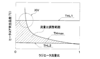
- the maximum outlet temperature which is the maximum value of the temperature of the air heated by the air heater, increases as the radiator-side flow rate ratio decreases.
- the increase rate of the maximum blowout temperature with respect to the decrease of the radiator side flow rate ratio becomes larger as the radiator side flow rate ratio becomes smaller.
- the air heated by the air heater can be heated to an appropriate temperature even when the radiator side flow rate ratio is small.
- a flow rate adjusting mechanism includes It is used for a refrigeration cycle apparatus including a high temperature heat medium circuit, an air heater, a radiator, a compressor, a high pressure side heat exchanger, a decompression unit, and an evaporator.
- the high temperature heat medium circulates in the high temperature heat medium circuit.
- the air heater heat-exchanges the high-temperature heat medium with the air blown into the vehicle compartment to heat the air blown into the vehicle compartment.
- the radiator causes the high-temperature heat medium to exchange heat with the air outside the vehicle compartment and radiates heat to the air outside the vehicle compartment.
- the compressor draws in the refrigerant, compresses it, and discharges it.
- the high-pressure heat exchanger exchanges heat between the high-pressure refrigerant discharged from the compressor and the high-temperature heat medium, and radiates heat from the refrigerant to the high-temperature heat medium.
- the decompression unit decompresses the refrigerant that has undergone heat exchange in the high-pressure side heat exchanger.
- the evaporator causes the refrigerant decompressed in the decompression unit to absorb heat and evaporate the refrigerant.
- the maximum blowout temperature which is the maximum value of the temperature of the air heated by the air heater, is the ratio of the flow rate of the high temperature heat medium flowing through the radiator to the flow rate of the high temperature heat medium flowing through the high pressure side heat exchanger. It increases as the radiator-side flow rate is decreased.
- the increase rate of the maximum blowout temperature with respect to the decrease of the radiator side flow rate ratio increases as the radiator side flow rate ratio decreases.
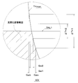
- the flow rate adjustment mechanism is such that, in the radiator side flow rate ratio when the maximum blowout temperature becomes the upper limit blowout temperature which is the upper limit value of the temperature of the air heated by the air heater, the fluctuation range of the maximum blowout temperature is equal to or less than the allowable value.
- the flow rate ratio on the radiator side can be adjusted so that
- the fluctuation range of the air heated by the air heater can be less than the allowable value, so that the air heater can appropriately heat the air.
- a flow rate adjusting mechanism includes It is used for a refrigeration cycle apparatus including a high temperature heat medium circuit, an air heater, a radiator, a compressor, a high pressure side heat exchanger, a decompression unit, and an evaporator.
- the high temperature heat medium circulates in the high temperature heat medium circuit.
- the air heater heat-exchanges the high-temperature heat medium with the air blown into the vehicle compartment to heat the air blown into the vehicle compartment.
- the radiator causes the high-temperature heat medium to exchange heat with the air outside the vehicle compartment and radiates heat to the air outside the vehicle compartment.
- the compressor draws in the refrigerant, compresses it, and discharges it.
- the high-pressure heat exchanger exchanges heat between the high-pressure refrigerant discharged from the compressor and the high-temperature heat medium, and radiates heat from the refrigerant to the high-temperature heat medium.
- the decompression unit decompresses the refrigerant that has undergone heat exchange in the high-pressure side heat exchanger.
- the evaporator causes the refrigerant decompressed in the decompression unit to absorb heat and evaporate the refrigerant.
- the flow rate adjustment mechanism can adjust the radiator side flow rate ratio, which is the ratio of the flow rate of the high temperature heat medium flowing through the radiator to the flow rate of the high temperature heat medium flowing through the high pressure side heat exchanger, with a predetermined resolution.
- the fluctuation range of the radiator side flow rate ratio can be appropriately controlled, so that the air heated by the air heater can be heated to an appropriate temperature.
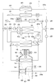
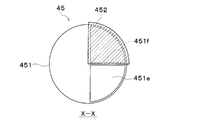
- FIG. 10 is a schematic XX cross-sectional view of FIG. 9, showing an example of an operating state of the high temperature side three-way valve. It is a typical sectional view showing an example of an operating state of a high temperature side three way valve. It is a typical sectional view showing an example of an operating state of a high temperature side three way valve. It is a graph which shows the relationship between the radiator flow volume ratio and heater core blowing temperature in 5th Embodiment. It is an enlarged view of the XIV section of FIG. It is the whole refrigeration cycle device lineblock diagram in a 6th embodiment.
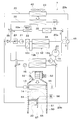
- the vehicle air conditioner 1 shown in FIGS. 1 to 4 is an air conditioner that adjusts the vehicle interior space (in other words, the air conditioning target space) to an appropriate temperature.
- the vehicle air conditioner 1 has a refrigeration cycle device 10.
- the refrigeration cycle device 10 is mounted on a hybrid vehicle that obtains a driving force for vehicle traveling from an engine (in other words, an internal combustion engine) and an electric motor for traveling.
- the hybrid vehicle of the present embodiment is configured as a plug-in hybrid vehicle in which electric power supplied from an external power source (in other words, commercial power source) when the vehicle is stopped can be charged into a battery (in other words, in-vehicle battery) mounted in the vehicle. Has been done.
- a battery in other words, in-vehicle battery
- the battery for example, a lithium ion battery can be used.
- the driving force output from the engine is used not only for running the vehicle, but also for operating the generator. Then, the electric power generated by the generator and the electric power supplied from the external power source can be stored in the battery, and the electric power stored in the battery constitutes not only the electric motor for traveling but also the refrigeration cycle device 10. It is supplied to various in-vehicle devices such as electric components.
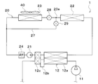
- the refrigeration cycle apparatus 10 is a vapor compression refrigerator including a compressor 11, a condenser 12, a first expansion valve 13, an air side evaporator 14, a constant pressure valve 15, a second expansion valve 16 and a cooling water side evaporator 17. is there.
- a CFC-based refrigerant is used as the refrigerant, and constitutes a subcritical refrigeration cycle in which the high-pressure side refrigerant pressure does not exceed the refrigerant critical pressure.
- the second expansion valve 16 and the cooling water side evaporator 17 are arranged in parallel with the first expansion valve 13, the air side evaporator 14 and the constant pressure valve 15 in the refrigerant flow.
- a first refrigerant circulation circuit and a second refrigerant circulation circuit are formed in the refrigeration cycle device 10.
- the refrigerant circulates in the order of the compressor 11, the condenser 12, the first expansion valve 13, the air side evaporator 14, the constant pressure valve 15, and the compressor 11.
- the refrigerant circulates in the order of the compressor 11, the condenser 12, the second expansion valve 16, and the cooling water side evaporator 17.
- the compressor 11 is an electric compressor driven by electric power supplied from a battery, and sucks, compresses, and discharges the refrigerant of the refrigeration cycle device 10.
- the electric motor of the compressor 11 is controlled by the control device 60.
- the compressor 11 may be a belt driven variable displacement compressor.
- the condenser 12 is a high pressure side heat exchanger for exchanging heat between the high pressure side refrigerant discharged from the compressor 11 and the cooling water of the high temperature cooling water circuit 20.
- the condenser 12 has a condenser 12a, a receiver 12b, and a supercooler 12c.
- the condenser 12a heat-exchanges the high pressure side refrigerant discharged from the compressor 11 with the cooling water of the high temperature cooling water circuit 20 to condense the high pressure side refrigerant.
- the cooling water of the high temperature cooling water circuit 20 is a fluid as a heat medium.
- the cooling water in the high temperature cooling water circuit 20 is a high temperature heat medium.
- a liquid containing at least ethylene glycol, dimethylpolysiloxane or a nanofluid, or an antifreezing liquid is used as the cooling water for the high temperature cooling water circuit 20.
- the high temperature cooling water circuit 20 is a high temperature heat medium circuit in which a high temperature heat medium circulates.
- the receiver 12b is a gas-liquid separation unit that separates the gas-liquid of the high-pressure refrigerant that has flowed out of the condenser 12 and causes the separated liquid-phase refrigerant to flow out to the downstream side, and also stores the excess refrigerant of the cycle.
- the supercooling unit 12c heat-exchanges the liquid-phase refrigerant flowing out from the receiver 12b with the cooling water of the high-temperature cooling water circuit 20 to supercool the liquid-phase refrigerant.
- the first expansion valve 13 is a first decompression unit that decompresses and expands the liquid-phase refrigerant flowing out from the receiver 12b.
- the first expansion valve 13 is a mechanical temperature expansion valve.
- the mechanical expansion valve is a temperature expansion valve that has a temperature sensing portion and drives a valve body by a mechanical mechanism such as a diaphragm.
- the air-side evaporator 14 is an evaporator that evaporates the refrigerant by exchanging heat between the refrigerant flowing out of the first expansion valve 13 and the air blown into the vehicle interior. In the air side evaporator 14, the refrigerant absorbs heat from the air blown into the vehicle interior.
- the air side evaporator 14 is an air cooler that cools the air blown into the vehicle interior.
- the constant pressure valve 15 is a pressure adjusting unit that maintains the pressure of the refrigerant on the outlet side of the air side evaporator 14 at a predetermined value.
- the constant pressure valve 15 is composed of a mechanical variable throttle mechanism. Specifically, the constant pressure valve 15 reduces the passage area (ie, throttle opening) of the refrigerant passage when the pressure of the refrigerant on the outlet side of the air side evaporator 14 falls below a predetermined value, and the outlet of the air side evaporator 14 is reduced. When the pressure of the refrigerant on the side exceeds a predetermined value, the passage area of the refrigerant passage (that is, the throttle opening) is increased. The vapor-phase refrigerant whose pressure is adjusted by the constant pressure valve 15 is sucked into the compressor 11 and compressed.
- the constant pressure valve 15 may be replaced with a fixed throttle composed of an orifice, a capillary tube, or the like.
- the second expansion valve 16 is a second decompression unit that decompresses and expands the liquid-phase refrigerant that has flowed out of the condenser 12.
- the second expansion valve 16 is an electric expansion valve.
- the electric expansion valve is an electric variable throttle mechanism including a valve body configured to change a throttle opening degree and an electric actuator that changes the opening degree of the valve body.
- the second expansion valve 16 can fully close the refrigerant passage.
- the second expansion valve 16 has a state in which the refrigerant flows to the air side evaporator 14 of the air side evaporator 14 and the cooling water side evaporator 17, and the refrigerant flows to both the air side evaporator 14 and the cooling water side evaporator 17. It is a refrigerant flow switching unit that switches between a flowing state and a flowing state.
- the operation of the second expansion valve 16 is controlled by a control signal output from the control device 60.
- the second expansion valve 16 may be a mechanical temperature expansion valve.
- an opening/closing valve that opens/closes the refrigerant flow path on the second expansion valve 16 side needs to be provided separately from the second expansion valve 16.
- the cooling water side evaporator 17 is an evaporator that evaporates the refrigerant by exchanging heat between the refrigerant flowing out of the second expansion valve 16 and the cooling water of the low temperature cooling water circuit 30. In the cooling water side evaporator 17, the refrigerant absorbs heat from the cooling water in the low temperature cooling water circuit 30.
- the cooling water side evaporator 17 is a heat medium cooler that cools the cooling water in the low temperature cooling water circuit 30. The vapor-phase refrigerant evaporated in the cooling water side evaporator 17 is sucked into the compressor 11 and compressed.
- the cooling water in the low temperature cooling water circuit 30 is a fluid as a heat medium.
- the cooling water in the low temperature cooling water circuit 30 is a low temperature heat medium.
- a liquid containing at least ethylene glycol, dimethylpolysiloxane, or a nanofluid, or an antifreeze liquid is used as the cooling water for the low-temperature cooling water circuit 30.
- the low temperature cooling water circuit 30 is a low temperature heat medium circuit in which a low temperature heat medium circulates.
- the high temperature cooling water circuit 20 is provided with a condenser 12, a high temperature side pump 21, a heater core 22, a high temperature side radiator 23, a high temperature side reserve tank 24, a heater core flow passage opening/closing valve 25 and a radiator flow passage opening/closing valve 26.
- the high temperature side pump 21 is a heat medium pump that sucks cooling water and discharges it.
- the high temperature side pump 21 is an electric pump.
- the high temperature side pump 21 is an electric pump having a constant discharge flow rate, but the high temperature side pump 21 may be an electric pump having a variable discharge flow rate.
- the heater core 22 is an air heater that heats the air blown into the vehicle interior by exchanging heat between the cooling water of the high-temperature cooling water circuit 20 and the air blown into the vehicle interior. In the heater core 22, the cooling water radiates heat to the air blown into the vehicle interior.
- the condenser 12 and the heater core 22 are air heating units that heat the air blown into the passenger compartment by radiating the high pressure refrigerant discharged from the compressor 11.
- the high temperature side radiator 23 is a radiator that causes the cooling water in the high temperature cooling water circuit 20 to exchange heat with the outside air to radiate heat from the cooling water to the outside air.
- the high temperature side reserve tank 24 is a cooling water storage unit that stores excess cooling water. By storing the surplus cooling water in the high temperature side reserve tank 24, it is possible to suppress a decrease in the amount of the cooling water circulating in each flow path.
- the high temperature side reserve tank 24 is a closed type reserve tank or an atmosphere open type reserve tank.
- the closed-type reserve tank is a reserve tank that brings the pressure on the liquid surface of the stored cooling water to a predetermined pressure.
- the open-air reserve tank is a reserve tank that brings the pressure on the liquid surface of the stored cooling water to atmospheric pressure.
- the condenser 12, the high temperature side pump 21, and the high temperature side reserve tank 24 are arranged in the condenser flow path 20a.
- the condenser passage 20a is a passage through which the cooling water of the high temperature cooling water circuit 20 flows.
- the heater core 22 and the heater core passage opening/closing valve 25 are arranged in the heater core passage 20b.
- the heater core passage 20b is a passage through which the cooling water of the high temperature cooling water circuit 20 flows.
- the heater core passage opening/closing valve 25 is an electromagnetic valve that opens and closes the heater core passage 20b. The operation of the heater core passage opening/closing valve 25 is controlled by the controller 60.
- the high temperature side radiator 23 and the radiator passage opening/closing valve 26 are arranged in the radiator passage 20c.
- the radiator passage 20c is a passage through which the cooling water of the high temperature cooling water circuit 20 flows in parallel to the heater core 22.
- the radiator passage opening/closing valve 26 is an electromagnetic valve that opens and closes the radiator passage 20c. The operation of the radiator passage opening/closing valve 26 is controlled by the controller 60.
- the heater core passage opening/closing valve 25 is arranged in the high temperature cooling water circuit 20 between the heater core 22 and the high temperature side branch portion 20 d which is a branch portion between the heater core passage 20 b and the radiator passage 20 c.
- the heater core passage opening/closing valve 25 adjusts the flow rate of cooling water in the high temperature cooling water circuit 20 flowing into the heater core 22.
- the radiator passage opening/closing valve 26 is arranged between the high temperature side branch portion 20 d and the high temperature side radiator 23 in the high temperature cooling water circuit 20.
- the radiator passage opening/closing valve 26 adjusts the flow rate of the cooling water of the high temperature cooling water circuit 20 flowing into the high temperature side radiator 23.
- the heater core passage opening/closing valve 25 and the radiator passage opening/closing valve 26 are high temperature heat medium adjusting units that adjust the flow rate ratio of the cooling water flowing through the heater core 22 and the cooling water flowing through the high temperature side radiator 23.
- the flow rate ratio between the cooling water flowing through the heater core 22 and the cooling water flowing through the high temperature side radiator 23 is the high temperature heat medium flow rate ratio.
- the radiator passage opening/closing valve 26 is a radiator-side adjusting unit.
- the heater core passage opening/closing valve 25 is an air heater side adjusting unit.
- the heater core channel opening/closing valve 25 and the radiator channel opening/closing valve 26 are a flow rate adjusting mechanism (in other words, a flow rate adjusting mechanism) that adjusts the flow rate of the cooling water.
- the low temperature cooling water circuit 30 is provided with a low temperature side pump 31, a cooling water side evaporator 17, a low temperature side radiator 32, a battery 33, a charger 34 and a low temperature side reserve tank 35.
- the low temperature side pump 31 is a heat medium pump that sucks in and discharges cooling water.
- the low temperature side pump 31 is an electric pump.
- the low temperature side radiator 32 is a heat absorber that causes the cooling water of the low temperature cooling water circuit 30 and the outside air to exchange heat with each other so that the cooling water of the low temperature cooling water circuit 30 absorbs heat from the outside air.
- the high temperature side radiator 23 and the low temperature side radiator 32 are arranged in series in this order in the flow direction of the outside air. Outside air is blown to the high temperature side radiator 23 and the low temperature side radiator 32 by an outdoor blower 40.
- the outdoor blower 40 is an outside air blowing unit that blows outside air toward the high temperature side radiator 23 and the low temperature side radiator 32.
- the outdoor blower 40 is an electric blower that drives a fan with an electric motor. The operation of the outdoor blower 40 is controlled by the control device 60.
- the high temperature side radiator 23, the low temperature side radiator 32 and the outdoor blower 40 are arranged at the forefront of the vehicle. Therefore, the traveling wind can be applied to the high temperature side radiator 23 and the low temperature side radiator 32 when the vehicle is traveling.
- the charger 34 is a device for charging the battery 33 with electric power.
- the battery 33 and the charger 34 are in-vehicle devices mounted on the vehicle, and are heat-generating devices that generate heat as they operate.
- the battery 33 and the charger 34 radiate the waste heat generated by the operation to the cooling water of the low temperature cooling water circuit 30. In other words, the battery 33 and the charger 34 supply heat to the cooling water of the low temperature cooling water circuit 30.
- the low temperature side reserve tank 35 is a cooling water storage unit that stores excess cooling water. By storing the surplus cooling water in the low temperature side reserve tank 35, it is possible to suppress the decrease in the amount of the cooling water circulating in each flow path.
- the low temperature side reserve tank 35 is a closed reserve tank or an atmosphere open reserve tank.
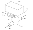
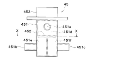
- a three-way valve 36 is arranged in the low temperature cooling water circuit 30.
- the three-way valve 36 is a low temperature heat medium adjustment unit that adjusts the flow rate ratio of the flow rate of the cooling water flowing to the battery 33 side and the flow rate of the cooling water flowing to the low temperature side radiator 32 side.
- the flow rate ratio of the flow rate of the cooling water flowing to the battery 33 side and the flow rate of the cooling water flowing to the low temperature side radiator 32 side is the low temperature heat medium flow rate ratio.
- the three-way valve 36 is a heat medium flow switching unit that switches between a state in which the cooling water flows in the low temperature side radiator 32 and a state in which the cooling water does not flow. The operation of the three-way valve 36 is controlled by the controller 60.
- the air side evaporator 14 and the heater core 22 are housed in the air conditioning casing 51 of the indoor air conditioning unit 50.
- the indoor air conditioning unit 50 is arranged inside the instrument panel (not shown) at the front of the passenger compartment.
- the air conditioning casing 51 is an air passage forming member that forms an air passage.
- the heater core 22 is arranged on the air flow downstream side of the air side evaporator 14 in the air passage inside the air conditioning casing 51.
- An inside/outside air switching box 52 and an indoor blower 53 are arranged in the air conditioning casing 51.
- the inside/outside air switching box 52 is an inside/outside air switching unit for switching and introducing inside air and outside air into the air passage in the air conditioning casing 51.
- the indoor blower 53 sucks and blows the inside air and the outside air introduced into the air passage in the air conditioning casing 51 through the inside/outside air switching box 52.
- the operation of the indoor blower 53 is controlled by the control device 60.
- An air mix door 54 is arranged between the air side evaporator 14 and the heater core 22 in the air passage in the air conditioning casing 51.
- the air mix door 54 adjusts the air volume ratio of the cool air flowing into the heater core 22 and the cool air flowing through the cold air bypass passage 55 among the cool air passing through the air side evaporator 14.
- the cold air bypass passage 55 is an air passage through which the cold air that has passed through the air side evaporator 14 flows through the heater core 22.
- the air mix door 54 is a revolving door having a rotating shaft rotatably supported by the air conditioning casing 51 and a door board portion connected to the rotating shaft. By adjusting the opening position of the air mix door 54, the temperature of the conditioned air blown from the air conditioning casing 51 into the vehicle interior can be adjusted to a desired temperature.
- the rotary shaft of the air mix door 54 is driven by the servo motor 56.
- the operation of the air mix door servomotor 56 is controlled by the controller 60.
- the air mix door 54 may be a slide door that slides in a direction substantially orthogonal to the air flow.
- the sliding door may be a plate-shaped door formed of a rigid body. It may be a film door formed of a flexible film material.
- the air-conditioned air whose temperature is adjusted by the air mix door 54 is blown into the vehicle interior from the air outlet 57 formed in the air-conditioning casing 51.
- the control device 60 shown in FIG. 2 is composed of a well-known microcomputer including a CPU, a ROM, a RAM, and the like and its peripheral circuits.
- the control device 60 performs various calculations and processes based on the control program stored in the ROM.
- Various controlled devices are connected to the output side of the control device 60.
- the control device 60 is a control unit that controls the operation of various controlled devices.
- the devices to be controlled by the control device 60 are the compressor 11, the second expansion valve 16, the heater core passage opening/closing valve 25, the radiator passage opening/closing valve 26, the three-way valve 36, the outdoor blower 40, the indoor blower 53, and the air mix.
- the software and hardware for controlling the electric motor of the compressor 11 of the control device 60 is a refrigerant discharge capacity control unit.
- the software and hardware that control the second expansion valve 16 of the control device 60 are a throttle control unit.
- the software and hardware that control the heater core passage opening/closing valve 25 and the radiator passage opening/closing valve 26 of the control device 60 are a high-temperature heat medium flow control unit.
- the software and hardware for controlling the three-way valve 36 of the control device 60 is a low temperature heat medium flow control unit.
- the software and hardware that control the outdoor blower 40 of the control device 60 are an outside air blowing capacity control unit.
- the software and hardware for controlling the indoor blower 53 of the control device 60 is an air blower capacity control unit.
- the software and hardware for controlling the air mix door servomotor 56 of the control device 60 is an air volume ratio control unit.
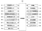
- an inside air temperature sensor 61 At the input side of the control device 60, an inside air temperature sensor 61, an outside air temperature sensor 62, a solar radiation amount sensor 63, an evaporator intake air temperature sensor 64, an evaporator temperature sensor 65, a heater core inlet cooling water temperature sensor 66, a battery inlet cooling water.
- Various control sensor groups such as a temperature sensor 67 and a battery temperature sensor 68 are connected.
- the inside air temperature sensor 61 detects the passenger compartment temperature Tr.
- the outside air temperature sensor 62 detects the outside air temperature Tam.
- the solar radiation amount sensor 63 detects the solar radiation amount Ts in the vehicle compartment.
- the evaporator suction air temperature sensor 64 is an air temperature detection unit that detects the temperature TEin of the air sucked into the air side evaporator 14.
- the evaporator temperature sensor 65 is a temperature detection unit that detects the temperature TE of the air side evaporator 14.
- the evaporator temperature sensor 65 is, for example, a fin thermistor that detects the temperature of the heat exchange fins of the air side evaporator 14 or a refrigerant temperature sensor that detects the temperature of the refrigerant flowing through the air side evaporator 14.
- the heater core inlet cooling water temperature sensor 66 is a heat medium temperature detecting unit that detects the temperature THin of the cooling water flowing into the heater core 22.
- the battery inlet cooling water temperature sensor 67 is a heat medium temperature detecting unit that detects the temperature of the cooling water flowing into the battery 33.
- the battery temperature sensor 68 is a battery temperature detection unit that detects the temperature of the battery 33. For example, the battery temperature sensor 68 detects the temperature of each cell of the battery 33.
- a variety of operation switches are connected to the input side of the control device 60.
- Various operation switches are provided on the operation panel 70 and are operated by an occupant.
- the operation panel 70 is arranged near the instrument panel at the front of the passenger compartment. Operation signals from various operation switches are input to the control device 60.
- Various operation switches are air conditioner switches, temperature setting switches, etc.
- the air conditioner switch sets whether or not the indoor air conditioning unit 50 cools the air.
- the temperature setting switch sets the set temperature in the vehicle compartment.
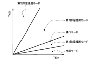
- the control device 60 sets the operation mode based on the intake air temperature TEin and the target outlet temperature TAO of the air side evaporator 14 and the control map shown in FIG. Switch.
- the operation modes include at least a cooling mode, a first dehumidifying and heating mode, a second dehumidifying and heating mode, and a third dehumidifying and heating mode.
- Target air temperature TAO is the target temperature of the air blown into the passenger compartment.
- the control device 60 calculates the target outlet temperature TAO based on the following mathematical formula.
- TAO Kset ⁇ Tset ⁇ Kr ⁇ Tr ⁇ Kam ⁇ Tam ⁇ Ks ⁇ Ts+C
- Tset is the vehicle interior temperature set by the temperature setting switch of the operation panel 70
- Tr is the inside air temperature detected by the inside air temperature sensor 61
- Tam is the outside air temperature detected by the outside air temperature sensor 62
- Ts is It is the amount of solar radiation detected by the solar radiation sensor 63.
- Kset, Kr, Kam, and Ks are control gains
- C is a correction constant.
- the first dehumidification heating mode ⁇ the second dehumidification heating mode ⁇ the third dehumidification heating mode is switched.
- the threshold value of the target outlet temperature TAO increases as the intake air temperature TEin of the air side evaporator 14 increases.
- the air blown into the passenger compartment is cooled by the air side evaporator 14 to cool the passenger compartment.
- the air blown into the vehicle compartment is cooled and dehumidified by the air side evaporator 14, and the air cooled and dehumidified by the air side evaporator 14 is heated by the heater core.
- the interior of the vehicle is dehumidified and heated.
- the heat quantity of the cooling water in the high-temperature cooling water circuit 20 is excessive with respect to the heat quantity required for the heater core 22, so that the surplus heat of the cooling water in the high-temperature cooling water circuit 20 is on the high temperature side.
- the radiator 23 radiates heat to the outside air.
- the first dehumidification heating mode is a heat dissipation mode in which the radiator 23 on the high temperature side radiates heat to the outside air.
- the heat quantity of the cooling water in the high-temperature cooling water circuit 20 is insufficient with respect to the heat quantity required for the heater core 22, so the low-temperature side radiator 32 absorbs the insufficient heat quantity from the outside air.
- the second dehumidification heating mode is a heat absorption mode in which the low temperature side radiator 32 absorbs heat from the outside air.
- the heat quantity of the cooling water in the high-temperature cooling water circuit 20 is insufficient with respect to the heat quantity required for the heater core 22, so that the insufficient heat quantity is outside the allowable range from the outside air in the low temperature side radiator 32. It absorbs heat at its maximum capacity.
- the control device 60 temporarily executes the transition mode when switching between the first dehumidification heating mode and the second dehumidification heating mode.
- the first dehumidification heating mode and the second dehumidification heating mode are executed at the same time. That is, in the transition mode, as in the first dehumidifying and heating mode, the high temperature side radiator 23 radiates the heat from the cooling water in the high temperature cooling water circuit 20 to the outside air, and as in the second dehumidifying and heating mode, the low temperature side radiator 32 lowers the temperature.
- the cooling water in the cooling water circuit 30 is made to absorb heat from the outside air. As a result, the switching between the first dehumidification heating mode and the second dehumidification heating mode becomes smooth.
- the control device 60 is connected to the control device 60 based on the target outlet temperature TAO, the detection signal of the sensor group, and the like.
- the operating states of the various control devices are determined.
- Cooling Mode In the cooling mode, the control device 60 operates the compressor 11 and the high temperature side pump 21. In the cooling mode, the controller 60 opens the heater core passage opening/closing valve 25 and opens the radiator passage opening/closing valve 26.
- the refrigerant flows as indicated by the broken line arrow in FIG. 1, and the state of the refrigerant circulating in the cycle changes as follows.
- the high-pressure refrigerant discharged from the compressor 11 flows into the condenser 12.
- the refrigerant flowing into the condenser 12 radiates heat to the cooling water in the high temperature cooling water circuit 20. As a result, the refrigerant is cooled and condensed in the condenser 12.
- the refrigerant flowing out of the condenser 12 flows into the first expansion valve 13 and is decompressed and expanded in the first expansion valve 13 until it becomes a low pressure refrigerant.
- the low-pressure refrigerant decompressed by the first expansion valve 13 flows into the air-side evaporator 14 and absorbs heat from the air blown into the vehicle interior to evaporate. As a result, the air blown into the vehicle interior is cooled.
- the refrigerant flowing out from the air side evaporator 14 flows to the suction side of the compressor 11 and is compressed again in the compressor 11.
- the low-pressure refrigerant in the air-side evaporator 14 can absorb heat from the air and blow the cooled air into the vehicle interior. As a result, cooling of the vehicle interior can be realized.
- the cooling water of the high temperature cooling water circuit 20 circulates in the high temperature side radiator 23 and is radiated from the cooling water to the outside air by the high temperature side radiator 23, as shown by the broken line arrow in FIG. It
- the cooling water of the high-temperature cooling water circuit 20 circulates in the heater core 22 as well, but the heat radiation amount from the cooling water to the air in the heater core 22 is adjusted by the air mix door 54. ..
- the control signal output to the servo motor of the air mix door 54 is determined so that the conditioned air whose temperature is adjusted by the air mix door 54 becomes the target outlet temperature TAO.
- the opening degree of the air mix door 54 is determined based on the target outlet temperature TAO, the temperature TE of the air side evaporator 14, the temperature THin of the cooling water flowing into the heater core 22, and the like.
- control device 60 opens the second expansion valve 16 at the throttle opening, and at the low temperature side so that the cooling water of the low temperature cooling water circuit 30 flows through the battery 33. It controls the pump 31 and the three-way valve 36.
- the refrigerant flowing out from the condenser 12 flows into the second expansion valve 16 and becomes a low-pressure refrigerant at the second expansion valve 16. It is expanded under reduced pressure.
- the low pressure refrigerant decompressed by the second expansion valve 16 flows into the cooling water side evaporator 17, and absorbs heat from the cooling water in the low temperature cooling water circuit 30 to evaporate.
- the cooling water in the low temperature cooling water circuit 30 is cooled.
- the cooling water circulates in the battery 33 to cool the battery 33, as indicated by the broken line arrow in FIG. 1.
- the flow rate of the cooling water flowing through the battery 33 is adjusted by the three-way valve 36 so that the battery 33 is cooled to the target battery temperature.
- the control device 60 operates the compressor 11 and the high temperature side pump 21.
- the heater core passage opening/closing valve 25 is opened, and the radiator passage opening/closing valve 26 is opened.
- the refrigerant flows as indicated by the broken line arrow in FIG. 1, and the state of the refrigerant circulating in the cycle changes as follows.
- the high-pressure refrigerant discharged from the compressor 11 flows into the condenser 12, exchanges heat with the cooling water in the high-temperature cooling water circuit 20, and radiates heat. As a result, the cooling water in the high temperature cooling water circuit 20 is heated.
- the refrigerant flowing out of the condenser 12 flows into the first expansion valve 13 and is decompressed and expanded in the first expansion valve 13 until it becomes a low pressure refrigerant.
- the low-pressure refrigerant decompressed by the first expansion valve 13 flows into the air-side evaporator 14 and absorbs heat from the air blown into the vehicle interior to evaporate. As a result, the air blown into the vehicle compartment is cooled and dehumidified.
- the refrigerant flowing out from the cooling water side evaporator 17 flows to the suction side of the compressor 11 and is compressed again in the compressor 11.
- the cooling water in the high-temperature cooling water circuit 20 circulates in the heater core 22 as shown by the solid arrow in FIG.
- the heater core 22 radiates heat from the cooling water in the high-temperature cooling water circuit 20 to the air blown into the vehicle interior. Therefore, the air that has been cooled and dehumidified by the air-side evaporator 14 is heated by the heater core 22 and blown into the vehicle interior.
- the cooling water circulates in the high temperature side radiator 23 and is radiated from the cooling water to the outside air in the high temperature side radiator 23, as shown by the dashed arrow in FIG.
- the heat of the high-pressure refrigerant discharged from the compressor 11 is radiated to the cooling water of the high-temperature cooling water circuit 20 by the condenser 12, and the cooling water of the high-temperature cooling water circuit 20 becomes The heat that the heater core 22 has can be radiated to the air, and the air heated by the heater core 22 can be blown into the vehicle interior.
- the air cooled and dehumidified by the air side evaporator 14 is heated. As a result, dehumidification and heating of the vehicle interior can be realized.
- the target outlet temperature TAO is performed in a relatively low temperature region, so the outlet air temperature of the heater core 22 may be relatively low. Therefore, the heat quantity of the cooling water in the high-temperature cooling water circuit 20 becomes excessive with respect to the heat quantity required in the heater core 22.
- the surplus heat of the cooling water in the high temperature cooling water circuit 20 is radiated to the outside air by the high temperature side radiator 23.
- the flow rate of the cooling water in the high temperature cooling water circuit 20 flowing through the high temperature side radiator 23 may be a flow rate capable of radiating the excess heat of the cooling water in the high temperature cooling water circuit 20 to the outside air.
- the opening degree is set so that the excess heat of the cooling water in the high temperature cooling water circuit 20 can be radiated to the outside air by the high temperature side radiator 23.
- the opening degree of the heater core passage opening/closing valve 25 is made larger than the opening degree of the radiator passage opening/closing valve 26.
- the flow rate of the cooling water in the high temperature cooling water circuit 20 flowing through the heater core 22 becomes higher than the flow rate of the cooling water in the high temperature cooling water circuit 20 flowing through the high temperature side radiator 23.
- the time average opening of the heater core passage opening/closing valve 25 may be larger than the time average opening of the radiator passage opening/closing valve 26.
- the heater core passage opening/closing valve 25 and the radiator passage opening/closing valve 26 are opened and closed intermittently, and the ratio of the opening time of the heater core passage opening/closing valve 25 is made larger than the ratio of the opening time of the radiator passage opening/closing valve 26. Accordingly, the time average opening degree of the heater core passage opening/closing valve 25 may be made larger than the time average opening degree of the radiator passage opening/closing valve 26.
- the opening ratio between the heater core passage opening/closing valve 25 and the radiator passage opening/closing valve 26 is the heat absorption amount Pa of air per unit time in the heater core 22 and the heat dissipation amount Pw of cooling water per unit time in the heater core 22. Can be determined using the relationship that are the same. The reason will be described below.
- the heat absorption amount Pa of the air per unit time in the heater core 22, which is required to heat the air to the target outlet temperature TAO in the heater core 22, is the specific heat and density of the air flowing in the heater core 22, and the air flowing into the heater core 22. Of temperature, the flow rate of air flowing through the heater core 22, and the target outlet temperature TAO.
- the flow rate of the air flowing through the heater core 22 is the same as the blow rate of the indoor blower 53.
- the amount of air blown from the indoor blower 53 can be calculated based on the rotation speed of the indoor blower 53 or the applied voltage.
- the temperature of the air flowing into the heater core 22 can be regarded as the same as the temperature TE of the air side evaporator 14 detected by the evaporator temperature sensor 65.
- the heat radiation amount Pw of the cooling water in the heater core 22 per unit time required to heat the air to the target outlet temperature TAO by the heater core 22 is determined by the specific heat and density of the cooling water flowing through the heater core 22 and the heater core 22. It can be calculated based on the flow rate of the cooling water flowing through, the temperature THin of the cooling water flowing into the heater core 22, and the target outlet temperature TAO.
- the flow rate of the cooling water flowing through the heater core 22 can be calculated based on the discharge flow rate of the high temperature side pump 21 and the opening ratio between the heater core passage opening/closing valve 25 and the radiator passage opening/closing valve 26.
- the heat absorption amount Pa of air per unit time in the heater core 22 is the same as the heat radiation amount Pw of cooling water per unit time in the heater core 22, it is possible to calculate the flow rate of cooling water that needs to flow into the heater core 22, Consequently, the opening ratio of the heater core passage opening/closing valve 25 and the radiator passage opening/closing valve 26 can be calculated.
- the control device 60 opens the second expansion valve 16 at the throttle opening degree so that the cooling water of the low temperature cooling water circuit 30 flows through the battery 33. Then, the low temperature side pump 31 and the three-way valve 36 are controlled.
- the refrigerant flowing out from the condenser 12 flows into the second expansion valve 16 and becomes a low-pressure refrigerant at the second expansion valve 16. It is expanded under reduced pressure.
- the low pressure refrigerant decompressed by the second expansion valve 16 flows into the cooling water side evaporator 17, and absorbs heat from the cooling water in the low temperature cooling water circuit 30 to evaporate.
- the cooling water in the low temperature cooling water circuit 30 is cooled.
- the cooling water circulates in the battery 33 to cool the battery 33, as indicated by the broken line arrow in FIG. 1.
- the flow rate of the cooling water flowing through the battery 33 is preferably adjusted by the three-way valve 36 so that the battery 33 is cooled to the target battery temperature.
- the method of adjusting the flow rate of the cooling water flowing through the battery 33 is the same as in the cooling mode.
- the control device 60 operates the compressor 11, the high temperature side pump 21, and the low temperature side pump 31. In the second dehumidifying and heating mode, the control device 60 opens the second expansion valve 16 with the throttle opening. In the second dehumidifying and heating mode, the control device 60 opens the heater core passage opening/closing valve 25 and closes the radiator passage opening/closing valve 26. In the second dehumidifying and heating mode, the control device 60 controls the three-way valve 36 so that the cooling water in the low temperature cooling water circuit 30 flows through the low temperature side radiator 32.
- the refrigerant flows as shown by the broken line arrows and solid line arrows in FIG. 1, and the state of the refrigerant circulating in the cycle changes as follows.
- the high-pressure refrigerant discharged from the compressor 11 flows into the condenser 12 and exchanges heat with the cooling water in the high-temperature cooling water circuit 20. Dissipate heat. As a result, the cooling water in the high temperature cooling water circuit 20 is heated.
- the refrigerant flowing out of the condenser 12 flows into the first expansion valve 13 and is decompressed and expanded in the first expansion valve 13 until it becomes a low pressure refrigerant.
- the low-pressure refrigerant decompressed by the first expansion valve 13 flows into the air-side evaporator 14 and absorbs heat from the air blown into the vehicle interior to evaporate. As a result, the air blown into the vehicle compartment is cooled and dehumidified.
- the refrigerant flowing out from the cooling water side evaporator 17 flows to the suction side of the compressor 11 and is compressed again in the compressor 11.
- the refrigerant flowing out from the condenser 12 flows into the second expansion valve 16 and becomes a low pressure refrigerant in the second expansion valve 16. Is decompressed and expanded.
- the low pressure refrigerant decompressed by the second expansion valve 16 flows into the cooling water side evaporator 17, and absorbs heat from the cooling water in the low temperature cooling water circuit 30 to evaporate. As a result, the cooling water in the low temperature cooling water circuit 30 is cooled.
- the cooling water in the high-temperature cooling water circuit 20 circulates in the heater core 22 as shown by the solid arrow in FIG.
- the air mix door 54 is located at the position indicated by the chain double-dashed line in FIG. The total flow rate of air is determined to pass through the heater core 22.
- the heater core 22 radiates heat from the cooling water in the high-temperature cooling water circuit 20 to the air blown into the vehicle interior. Therefore, the air that has been cooled and dehumidified by the air-side evaporator 14 is heated by the heater core 22 and blown into the vehicle interior.
- the radiator passage opening/closing valve 26 is closed, the cooling water in the high temperature side cooling water circuit 20 does not circulate in the high temperature side radiator 23. Therefore, the radiator 23 does not radiate heat from the cooling water to the outside air.
- the cooling water of the low temperature cooling water circuit 30 circulates in the low temperature side radiator 32, and the low temperature side radiator 32 cools the low temperature cooling water.
- the cooling water of the circuit 30 absorbs heat from the outside air.
- the heat of the high-pressure refrigerant discharged from the compressor 11 is radiated to the cooling water of the high-temperature cooling water circuit 20 by the condenser 12, and the cooling water of the high-temperature cooling water circuit 20 becomes The heat that the heater core 22 has can be radiated to the air, and the air heated by the heater core 22 can be blown into the vehicle interior.
- the air cooled and dehumidified by the air side evaporator 14 is heated. As a result, dehumidification and heating of the vehicle interior can be realized.
- the target outlet temperature TAO is performed in a higher temperature region than in the first dehumidification heating mode, so it is necessary to make the air temperature blown out of the heater core 22 higher than in the first dehumidification heating mode. is there.
- the cooling water in the low temperature cooling water circuit 30 absorbs heat from the outside air in the low temperature side radiator 32, the amount of heat available in the heater core 22 can be increased as compared with the first dehumidifying and heating mode, and the temperature of the air blown from the heater core 22 can be increased. Can be increased.
- the flow rate of the cooling water in the low temperature cooling water circuit 30 flowing through the low temperature side radiator 32 is set so that the low temperature side radiator 32 can absorb the heat required to heat the air by the heater core 22 to the target outlet temperature TAO.
- the three-way valve 36 is controlled to increase the flow rate of the cooling water.
- control device 60 opens the second expansion valve 16 at the throttle opening degree and causes the cooling water of the low temperature cooling water circuit 30 to flow through the battery 33. To control the three-way valve 36.
- the refrigerant flowing out from the condenser 12 flows into the second expansion valve 16 and becomes a low-pressure refrigerant at the second expansion valve 16. It is expanded under reduced pressure.
- the low pressure refrigerant decompressed by the second expansion valve 16 flows into the cooling water side evaporator 17, and absorbs heat from the cooling water in the low temperature cooling water circuit 30 to evaporate.
- the cooling water in the low temperature cooling water circuit 30 is cooled.
- the cooling water circulates in the battery 33 to cool the battery 33, as indicated by the broken line arrow in FIG. 1.
- the flow rate of the cooling water flowing through the battery 33 is preferably adjusted by the three-way valve 36 so that the battery 33 is cooled to the target battery temperature.
- the method of adjusting the flow rate of the cooling water flowing through the battery 33 is the same as in the cooling mode.
- the target air temperature TAO is higher than that in the second dehumidification heating mode, so the temperature of air blown from the heater core 22 is set to the second dehumidification heating mode. Need to be higher than
- the amount of heat absorbed from the outside air in the low temperature side radiator 32 is increased as compared with the second dehumidification heating mode.
- the three-way valve 36 is controlled so that the flow rate of the cooling water flowing through the low temperature side radiator 32 becomes maximum.
- the amount of heat that can be used in the heater core 22 can be increased as compared with the second dehumidifying and heating mode, and the temperature of air blown from the heater core 22 can be increased.
- control device 60 opens the second expansion valve 16 at the throttle opening and causes the cooling water of the low temperature cooling water circuit 30 to flow through the battery 33. To control the three-way valve 36.
- the refrigerant flowing out from the condenser 12 flows into the second expansion valve 16 and becomes a low-pressure refrigerant at the second expansion valve 16. It is expanded under reduced pressure.
- the low pressure refrigerant decompressed by the second expansion valve 16 flows into the cooling water side evaporator 17, and absorbs heat from the cooling water in the low temperature cooling water circuit 30 to evaporate.
- the cooling water in the low temperature cooling water circuit 30 is cooled.
- the cooling water circulates in the battery 33 to cool the battery 33, as indicated by the broken line arrow in FIG. 1.
- the flow rate of the cooling water flowing through the battery 33 is preferably adjusted by the three-way valve 36 so that the battery 33 is cooled to the target battery temperature.
- the method of adjusting the flow rate of the cooling water flowing through the battery 33 is the same as in the cooling mode.
- the control device 60 operates the compressor 11, the high temperature side pump 21, and the low temperature side pump 31. In the transition mode, the control device 60 opens the second expansion valve 16 with the throttle opening. In the transition mode, the heater core passage opening/closing valve 25 is opened, and the radiator passage opening/closing valve 26 is opened. In the transition mode, the control device 60 controls the three-way valve 36 so that the cooling water of the low temperature cooling water circuit 30 flows through the low temperature side radiator 32.
- the refrigerant flows as indicated by the broken line arrow and the solid line arrow in FIG. 1, and the state of the refrigerant circulating in the cycle changes as follows.
- the high-pressure refrigerant discharged from the compressor 11 flows into the condenser 12 and exchanges heat with the cooling water in the high-temperature cooling water circuit 20. Dissipate heat. As a result, the cooling water in the high temperature cooling water circuit 20 is heated.
- the refrigerant flowing out of the condenser 12 flows into the first expansion valve 13 and is decompressed and expanded in the first expansion valve 13 until it becomes a low pressure refrigerant.
- the low-pressure refrigerant decompressed by the first expansion valve 13 flows into the air-side evaporator 14 and absorbs heat from the air blown into the vehicle interior to evaporate. As a result, the air blown into the vehicle compartment is cooled and dehumidified.
- the refrigerant flowing out from the cooling water side evaporator 17 flows to the suction side of the compressor 11 and is compressed again in the compressor 11.
- the refrigerant flowing out from the condenser 12 flows into the second expansion valve 16 and becomes a low pressure refrigerant in the second expansion valve 16. Is decompressed and expanded.
- the low pressure refrigerant decompressed by the second expansion valve 16 flows into the cooling water side evaporator 17, and absorbs heat from the cooling water in the low temperature cooling water circuit 30 to evaporate. As a result, the cooling water in the low temperature cooling water circuit 30 is cooled.
- the cooling water in the high-temperature cooling water circuit 20 circulates in the heater core 22 as shown by the solid arrow in FIG.
- the heater core 22 radiates heat from the cooling water in the high-temperature cooling water circuit 20 to the air blown into the vehicle interior. Therefore, the air that has been cooled and dehumidified by the air-side evaporator 14 is heated by the heater core 22 and blown into the vehicle interior.
- the cooling water of the high temperature cooling water circuit 20 circulates in the high temperature side radiator 23 and is radiated from the cooling water to the outside air by the high temperature side radiator 23, as shown by the broken line arrow in FIG. It
- the cooling water of the low-temperature cooling water circuit 30 circulates in the low-temperature side radiator 32, and the low-temperature side radiator 32 operates to cool the low-temperature cooling water circuit 30.
- the cooling water absorbs heat from the outside air.
- the heat of the high-pressure refrigerant discharged from the compressor 11 is radiated to the cooling water of the high-temperature cooling water circuit 20 by the condenser 12, and the heat of the cooling water of the high-temperature cooling water circuit 20 is released.
- the heater core 22 can radiate heat to the air, and the air heated by the heater core 22 can be blown into the vehicle interior.
- the air cooled and dehumidified by the air side evaporator 14 is heated. As a result, dehumidification and heating of the vehicle interior can be realized.
- the cooling water in the low temperature cooling water circuit 30 absorbs heat from the outside air in the low temperature side radiator 32, the amount of heat available in the heater core 22 can be increased similarly to the second dehumidifying and heating mode, and the temperature of the air blown from the heater core 22 can be increased. Can be increased.
- the flow rate of the cooling water in the low temperature cooling water circuit 30 flowing through the low temperature side radiator 32 is adjusted in the same manner as in the second dehumidifying and heating mode. That is, the three-way valve 36 is controlled similarly to the second dehumidifying and heating mode.
- surplus heat of the cooling water in the high temperature cooling water circuit 20 is radiated to the outside air by the high temperature side radiator 23.
- the flow rate of the cooling water in the high temperature cooling water circuit 20 flowing through the high temperature side radiator 23 is adjusted in the same manner as in the first dehumidifying and heating mode. That is, the opening degrees of the heater core passage opening/closing valve 25 and the radiator passage opening/closing valve 26 are determined as in the first dehumidifying and heating mode.
- control device 60 opens the second expansion valve 16 at the throttle opening and also controls the three-way valve so that the cooling water of the low temperature cooling water circuit 30 flows through the battery 33. Control 36.
- the refrigerant flowing out from the condenser 12 flows into the second expansion valve 16 and becomes a low-pressure refrigerant at the second expansion valve 16. It is expanded under reduced pressure.
- the low pressure refrigerant decompressed by the second expansion valve 16 flows into the cooling water side evaporator 17, and absorbs heat from the cooling water in the low temperature cooling water circuit 30 to evaporate.
- the cooling water in the low temperature cooling water circuit 30 is cooled.
- the cooling water circulates in the battery 33 to cool the battery 33, as indicated by the broken line arrow in FIG. 1.
- the flow rate of the cooling water flowing through the battery 33 is preferably adjusted by the three-way valve 36 so that the battery 33 is cooled to the target battery temperature.
- the method of adjusting the flow rate of the cooling water flowing through the battery 33 is the same as in the cooling mode.
- the high temperature side radiator 23 radiates the heat from the cooling water in the high temperature cooling water circuit 20 to the outside air, and as in the second dehumidifying and heating mode, the low temperature side radiator 32 cools the low temperature cooling water.
- the cooling water of the circuit 30 is made to absorb heat from the outside air.
- control device 60 heats the air blown into the vehicle interior by the heater core 22 to the target outlet temperature TAO among the heat radiated from the refrigerant to the cooling water of the high temperature cooling water circuit 20 in the condenser 12.
- the heater core passage opening/closing valve 25 and the radiator passage opening/closing valve 26 are controlled so that a surplus heat with respect to the heat required to perform the heat dissipation has a flow rate ratio in which the high temperature side radiator 23 radiates heat to the air outside the vehicle compartment. ..
- the heat medium can be passed through the heater core 22 so that the heat necessary for heating the air blown into the vehicle interior by the heater core 22 to the target outlet temperature TAO is distributed to the heater core 22. Therefore, the air blown into the vehicle compartment can be appropriately heated by the heater core 22.
- the control device 60 determines that the time average flow rate of the cooling water in the high-temperature cooling water circuit 20 of the heater core 22 is on the high temperature side.
- the heater core passage opening/closing valve 25 and the radiator passage opening/closing valve 26 are controlled so as to be higher than the time average flow rate of the cooling water in the high temperature cooling water circuit 20 in the radiator 23. As a result, it is possible to reliably prevent the air heating capacity of the heater core 22 from becoming insufficient.
- the radiator passage opening/closing valve 26 is arranged between the condenser 12 and the high temperature side radiator 23 in the flow of the cooling water of the high temperature cooling water circuit 20, and the high temperature cooling flowing into the high temperature side radiator 23.
- the flow rate of cooling water in the water circuit 20 is adjusted. As a result, the excess heat can be surely radiated to the air outside the vehicle compartment by the high temperature radiator 23.
- the heater core 22 and the high temperature side radiator 23 are arranged in parallel with each other in the flow of cooling water in the high temperature cooling water circuit 20.
- the heater core passage opening/closing valve 25 is arranged between the high temperature side branch portion 20 d and the heater core 22 in the flow of the cooling water of the high temperature cooling water circuit 20, and the cooling water of the high temperature cooling water circuit 20 flowing into the heater core 22. Adjust the flow rate of. As a result, the excess heat can be more surely radiated to the air outside the vehicle compartment by the high temperature side radiator 23.
- the refrigeration cycle device 10 of the present embodiment includes a cooling water side evaporator 17.
- the cooling water side evaporator 17 heat-exchanges the refrigerant decompressed by the second expansion valve 16 with the cooling water of the low temperature cooling water circuit 30 to evaporate the refrigerant and cool the cooling water of the low temperature cooling water circuit 30.
- the cooling water in the low temperature cooling water circuit 30 can be cooled.
- the low temperature side radiator 32 causes the cooling water in the low temperature cooling water circuit 30 to exchange heat with the outside air to cause the cooling water in the low temperature cooling water circuit 30 to absorb heat from the outside air.
- control device 60 executes the transition mode when switching between the first dehumidification heating mode and the second dehumidification heating mode.
- the controller 60 determines that the flow rate ratio between the cooling water of the low temperature cooling water circuit 30 flowing through the low temperature side radiator 32 and the cooling water of the low temperature cooling water circuit 30 cooling the battery 33 is such that the battery 33 has the target battery temperature.
- the operation of the three-way valve 36 is controlled so that the flow rate ratio is cooled to 1.
- the cooling water of the low-temperature cooling water circuit 30 can be flown to the battery 33 so that the battery 33 reaches the target battery temperature. Therefore, the battery 33 can be appropriately cooled while heating the air blown into the vehicle interior.
- the battery 33 is cooled by the cooling water in the low temperature cooling water circuit 30. Thereby, the battery 33 can be cooled efficiently.
- the charger 34 is cooled by the cooling water in the low temperature cooling water circuit 30. Thereby, the charger 34 can be cooled efficiently.
- the air side evaporator 14 heat-exchanges the refrigerant decompressed by the first expansion valve 13 with the air blown into the vehicle interior to cool the air blown into the vehicle interior.
- the heater core 22 and the high temperature side radiator 23 are arranged in parallel with each other in the flow of the cooling water of the high temperature cooling water circuit 20, but in the present embodiment, as shown in FIG.
- the side radiators 23 are arranged in series with each other in the cooling water flow of the high temperature cooling water circuit 20.
- a bypass passage 27 is provided in the high temperature cooling water circuit 20.
- the bypass flow passage 27 is a bypass portion in which the cooling water of the high temperature cooling water circuit 20 flows by bypassing the high temperature side radiator 23.
- a flow rate adjusting valve 28 is arranged in a portion of the cooling water flow path of the high temperature cooling water circuit 20 where the cooling water flows in parallel with the bypass flow path 27.
- the flow rate adjusting valve 28 is an electromagnetic valve that can open and close the cooling water flow path and arbitrarily adjust the opening degree of the cooling water flow path. The operation of the flow rate adjusting valve 28 is controlled by the controller 60.
- the flow rate adjusting valve 28 is arranged in the high temperature cooling water circuit 20 between the bypass branch portion 20 e which is a branch portion of the bypass flow passage 27 and the high temperature side radiator 23.
- the flow rate adjusting valve 28 is a high temperature heat medium adjusting unit that adjusts the flow rate ratio between the cooling water flowing through the high temperature side radiator 23 and the cooling water flowing through the bypass passage 27.
- the flow rate ratio between the cooling water flowing through the high temperature side radiator 23 and the cooling water flowing through the bypass passage 27 is the bypass flow rate ratio.
- the flow rate adjusting valve 28 is a flow rate adjusting unit (in other words, a flow rate adjusting mechanism) that adjusts the flow rate of the cooling water.
- the flow rate adjusting valve 28 adjusts the flow rate ratio between the cooling water flowing through the heater core 22 and the cooling water flowing through the high temperature side radiator 23.
- a bypass opening/closing valve 29 is arranged in the bypass flow passage 27.
- the bypass opening/closing valve 29 is an electromagnetic valve that opens/closes the bypass flow passage 27.
- the operation of the bypass opening/closing valve 29 is controlled by the control device 60.
- the flow rate ratio between the flow rate of the cooling water flowing through the heater core 22 and the flow rate of the cooling water flowing through the high temperature side radiator 23 can be adjusted by adjusting the opening degree of the flow rate adjusting valve 28 and the opening degree of the bypass opening/closing valve 29.
- the flow rate on the heater core side is made higher than the flow rate on the high temperature side radiator side, as in the first embodiment.
- the heater core 22 and the high temperature side radiator 23 are arranged in series with each other in the flow of the cooling water in the high temperature cooling water circuit 20.
- the heater core 22 is arranged upstream of the high temperature side radiator 23 in the cooling water of the high temperature cooling water circuit 20.
- the bypass opening/closing valve 29 adjusts the flow rate ratio between the cooling water of the high temperature cooling water circuit 20 flowing through the high temperature side radiator 23 and the cooling water of the high temperature cooling water circuit 20 flowing through the bypass flow passage 27, thereby increasing the high temperature flowing through the heater core 22.
- the flow rate ratio between the cooling water of the cooling water circuit 20 and the cooling water of the high temperature cooling water circuit 20 flowing through the high temperature side radiator 23 is adjusted.
- the pressure of the refrigerant in the air side evaporator 14 is made higher than that in the air side evaporator 14 by the constant pressure valve 15.
- the constant pressure valve 15 is not provided on the outlet side of the evaporator 17
- the refrigerant pressure in the cooling water side evaporator 17 becomes the same as the refrigerant pressure in the air side evaporator 14.
- the heat absorption amount in the air side evaporator 14 and the cooling water side evaporator 17 is excessive with respect to the heat amount required in the heater core 22.
- the surplus heat is radiated to the outside air by the high temperature side radiator 23.
- the flow rate ratio between the flow rate of the cooling water flowing through the heater core 22 and the flow rate of the cooling water flowing through the high temperature side radiator 23, that is, the opening ratio between the heater core passage opening/closing valve 25 and the radiator passage opening/closing valve 26, is the same as in the first embodiment. It may be determined in the same manner as.
- the high temperature side radiator 23 and the low temperature side radiator 32 are joined to each other by a common fin 37.
- the common fin 37 is a heat exchange promotion member that promotes heat exchange between cooling water and air.
- the common fin 37 is a member made of metal (for example, aluminum).
- the common fin 37 is a connecting portion that transfers heat from the high temperature side radiator 23 to the low temperature side radiator 32 by connecting the high temperature side radiator 23 and the low temperature side radiator 32 with a metal.
- the high temperature side radiator 23 and the low temperature side radiator 32 are connected to each other by the common fins 37 so that heat can be transferred, the heat of the cooling water in the high temperature cooling water circuit 20 is transferred from the high temperature side radiator 23 to the low temperature side radiator 32. Move to.
- the temperature of the low temperature side radiator 32 rises, and the frost adhering to the surface of the low temperature side radiator 32 can be melted.
- the flow ratio between the cooling water flowing through the heater core 22 and the cooling water flowing through the high temperature side radiator 23 is adjusted by the heater core passage opening/closing valve 25 and the radiator passage opening/closing valve 26. As shown in, the flow rate ratio between the cooling water flowing through the heater core 22 and the cooling water flowing through the high temperature side radiator 23 is adjusted by the high temperature side three-way valve 45.
- the high temperature side three-way valve 45 is a flow rate adjusting unit (in other words, a flow rate adjusting mechanism) that adjusts the flow rate of the cooling water.
- the high temperature side three-way valve 45 is arranged in the high temperature side branch portion 20d, and adjusts the opening ratio between the heater core flow passage 20b and the radiator flow passage 20c. Therefore, the high temperature side three-way valve 45 adjusts the flow rate ratio of the cooling water flowing through the heater core 22 and the cooling water flowing through the high temperature side radiator 23. In other words, the high temperature side three-way valve 45 adjusts the ratio Gw of the flow rate of the cooling water flowing into the high temperature side radiator 23 to the flow rate of the cooling water heated by the condenser 12 (hereinafter, referred to as radiator flow rate ratio). To do.
- the radiator flow rate ratio is a radiator side flow rate ratio.
- the high temperature side three-way valve 45 has a housing 451, a valve body 452, and an actuator 453.
- the housing 451 has a cooling water inlet 451a, a heater core side outlet 451b, and a radiator side outlet 451c.
- the cooling water inlet 451a is a heat medium inlet.
- the cooling water inlet 451a is connected to the condenser flow path 20a.
- the heater core side outlet 451b is connected to the heater core flow path 20b.
- the radiator side outlet 451c is connected to the radiator flow path 20c.
- a cooling water inlet space 451d Inside the housing 451, a cooling water inlet space 451d, a heater core side space 451e, and a radiator side space 451f are formed.
- the cooling water inlet space 451d is a heat medium inlet space.
- the cooling water inlet space 451d communicates with the cooling water inlet 451a.
- the heater core side space 451e communicates with the heater core side outlet 451b.
- the radiator side space 451f communicates with the radiator side outlet 451c.
- the heater core side space 451e and the radiator side space 451f are in communication with the cooling water inlet space 451d.
- the heater core side space 451e and the radiator side space 451f are adjacent to each other.
- the valve body 452 changes the communication state between the heater core side space 451e and the radiator side space 451f and the cooling water inlet space 451d by opening and closing the heater core side space 451e and the radiator side space 451f.
- the valve body 452 adjusts the opening degree of the heater core side space 451e and the radiator side space 451f, thereby adjusting the opening degree ratio between the heater core passage 20b and the radiator passage 20c.
- the valve body 452 is rotationally operated by the rotational driving force of the actuator 453.
- the operation of the actuator 453 is controlled by the control device 60.
- valve body 452 shows examples of the operating state of the valve body 452.
- the valve body 452 opens the heater core side space 451e and closes the radiator side space 451f.
- the valve body 452 closes the heater core side space 451e and opens the radiator side space 451f.
- valve body 452 partially opens the heater core side space 451e and the radiator side space 451f.
- the high temperature side three-way valve 45 can arbitrarily adjust the flow rate ratio between the cooling water flowing through the heater core 22 and the cooling water flowing through the high temperature side radiator 23. In other words, the high temperature side three-way valve 45 can arbitrarily adjust the radiator flow rate ratio Gw.
- the minimum resolution of the radiator flow ratio in the high temperature side three-way valve 45 is the minimum fluctuation amount of the radiator flow rate ratio when the high temperature side three way valve 45 adjusts the radiator flow rate ratio.
- the minimum resolution of the radiator flow rate ratio in the high temperature side three-way valve 45 is the minimum adjustment range of the radiator flow rate ratio in the high temperature side three-way valve 45. That is, the smaller the minimum resolution of the high temperature side three-way valve 45, the finer the radiator flow ratio can be adjusted.
- FIG. 13 shows the relationship between the radiator flow rate ratio Gw and the temperature TH of the air blown from the heater core 22 (hereinafter referred to as the heater core blow temperature).
- the relationship between the radiator flow rate ratio Gw and the heater core outlet temperature TH shown in FIG. 13 is that the high temperature side three-way valve 45 is set so that the radiator flow rate ratio decreases from 1 to 0 under the following conditions (1) to (3). It is a result of measuring the heater core blowout temperature TH when the control is performed.
- the inside air introduction mode is an operation mode in which the inside/outside air switching box 52 introduces the inside air into the air passage in the air conditioning casing 51.
- the compressor 11 is controlled so that the heat absorption amount of the refrigeration cycle 1 (in other words, dehumidifying capacity or battery cooling capacity) becomes constant.
- the compressor 11 is controlled so that the temperature TE of the air side evaporator 14 becomes a constant temperature (for example, 2° C.).
- the compressor 11 is controlled so that the temperature TE of the cooling water cooled by the cooling water side evaporator 17 becomes a constant temperature.
- the rotation speed of the high temperature side pump 21 is controlled to be constant. Specifically, in the high temperature cooling water circuit 20, the rotation speed of the high temperature side pump 21 is controlled so that the flow rate of the cooling water is sufficient to transport the heat by the cooling water. For example, the rotation speed of the high temperature side pump 21 is controlled so that the cooling water flow rate is 10 L/min.
- the hatched area in the graph of FIG. 13 indicates the adjustment range of the radiator flow ratio Gw.
- the hatched area in the graph of FIG. 13 represents a straight line indicating the upper limit value THL1 (hereinafter, referred to as the upper limit blow temperature) of the heater core blow temperature TH and the lower limit value THL2 (hereinafter, called the lower limit blow temperature) of the heater core blow temperature TH. Is a region surrounded by a straight line and a curve representing the maximum value THmax of the heater core outlet temperature TH (hereinafter referred to as the maximum outlet temperature).
- the heater core 22 is required to blow out air having a temperature equal to or higher than the lower limit outlet temperature THL2 and equal to or lower than the upper limit outlet temperature THL1.
- the maximum blowout temperature THmax is the heater core blowout temperature TH when the air heating capacity of the heater core 22 is maximized.
- the upper limit outlet temperature THL1, the lower limit outlet temperature THL2 and the maximum outlet temperature THmax are expressed by the following formulas f1 to f3 using the radiator flow rate ratio Gw.
- THL1 55 (f1)
- THL2 -1.54Gw+5.3 (f2)
- THmax 5.502 Gw -1.173 (f3) That is, the maximum blowout temperature THmax increases as the radiator flow rate ratio Gw decreases. In other words, the curve representing the maximum outlet temperature THmax has a negative slope.
- the negative slope of the curve representing the maximum outlet temperature THmax increases as the radiator flow rate ratio Gw decreases. That is, the curve representing the maximum blowout temperature THmax has a larger slope as the radiator flow rate ratio Gw is smaller. In other words, the increase rate of the maximum blowout temperature THmax with respect to the decrease of the radiator flow rate ratio Gw is larger as the radiator flow rate ratio Gw is smaller.
- the first fluctuation range ⁇ TH1 shown in FIG. 13 is an allowable value of the fluctuation range of the heater core outlet temperature TH.
- the first fluctuation range ⁇ TH1 is 7° C., and more specifically, ⁇ 3.5° C. around the upper limit outlet temperature THL1.
- the first fluctuation range ⁇ TH1 is a fluctuation range of the heater core outlet temperature TH, which is considered as a boundary of whether or not the occupant feels uncomfortable.
- the first adjustment amount Gw1 shown in FIG. 13 is the adjustment amount of the radiator flow rate Gw corresponding to the first fluctuation width ⁇ TH1 of the heater core outlet temperature TH when the maximum outlet temperature THmax matches the upper limit outlet temperature THL1. .. In this example, the first adjustment amount Gw1 is 0.014.
- the minimum resolution of the high temperature side three-way valve 45 is less than or equal to the first adjustment amount Gw1. Specifically, the minimum resolution of the high temperature side three-way valve 45 is set to the first adjustment amount Gw1 or less by setting the gear ratio between the actuator 453 of the high temperature side three-way valve 45 and the valve body 452.
- the high temperature side three-way valve 45 adjusts the radiator flow rate ratio Gw, the fluctuation range of the heater core blowing temperature TH can be suppressed within the first fluctuation range ⁇ TH1, so that the passenger feels uncomfortable due to the fluctuation of the blowing temperature. Can be prevented.
- the minimum resolution Gwmin of the high temperature side three-way valve 45 can be expressed by the following formulas f4 to f7.
- Gwmin ⁇ Gw1 (f4)
- Gw1 Gwa-Gwb (f5)
- Gwa f -1 (THL1- ⁇ TH1/2) (f6)
- Gwb f ⁇ 1 (THL1+ ⁇ TH1/2) (f7)
- Gwa is a radiator flow rate ratio Gw corresponding to the heater core outlet temperature TH at the lower limit of the first fluctuation width ⁇ TH1.
- Gwb is the radiator flow rate ratio Gw corresponding to the heater core outlet temperature TH at the upper limit of the first fluctuation width ⁇ TH1.
- the minimum resolution Gwmin of the high temperature side three-way valve 45 satisfies the relationship of the following mathematical expression f8.
- the second fluctuation width ⁇ TH2 shown in FIG. 13 is an error width of the temperature detected by the heater core inlet cooling water temperature sensor 66.
- the second fluctuation range ⁇ TH2 is 0.4° C., and more specifically, it is ⁇ 0.2° C. around the upper limit outlet temperature THL1.
- the temperature detected by the heater core inlet cooling water temperature sensor 66 can be regarded as the heater core outlet temperature TH.
- the second fluctuation range ⁇ TH2 may be an error range of the temperature detected by the sensor that detects the heater core outlet temperature TH.
- the second adjustment amount Gw2 shown in FIG. 13 is the adjustment amount of the radiator flow rate Gw corresponding to the second fluctuation range ⁇ TH2 of the heater core outlet temperature TH when the maximum outlet temperature THmax matches the upper limit outlet temperature THL1. .. In this example, the second adjustment amount Gw2 is 0.0008.
- the minimum resolution of the high temperature side three-way valve 45 is equal to or greater than the second adjustment amount Gw2. Specifically, the minimum resolution of the high temperature side three way valve 45 is set to the second adjustment amount Gw2 or more by setting the gear ratio between the actuator 453 of the high temperature side three way valve 45 and the valve body 452. Accordingly, when the high temperature side three-way valve 45 adjusts the radiator flow rate ratio Gw, the fluctuation range of the heater core outlet temperature TH can be set to the second fluctuation range ⁇ TH2 or more. It is avoided that the minimum resolution of the side three-way valve 45 becomes small.
- the maximum outlet temperature THmax increases as the radiator flow ratio Gw decreases, and the increase rate of the maximum outlet temperature THmax with respect to the decrease in the radiator flow ratio Gw is equal to the radiator flow ratio Gw. The smaller it gets, the bigger it gets.
- the air heated by the heater core 22 can be heated to an appropriate temperature even when the radiator flow ratio Gw is small.
- the high temperature side three-way valve 45 in the radiator flow ratio Gw when the maximum blowout temperature THmax reaches the upper limit blowout temperature THL1, the high temperature side three-way valve 45 has a variation range in which the maximum blowout temperature THmax varies by a first variation range.
- the radiator flow rate ratio Gw can be adjusted so as to be ⁇ TH1 or less.
- the high temperature side three-way valve 45 adjusts the radiator flow rate ratio Gw, the fluctuation range of the heater core blowing temperature TH can be suppressed within the first fluctuation range ⁇ TH1, so that the passenger feels uncomfortable due to the fluctuation of the blowing temperature. Can be prevented.
- the high temperature side three-way valve 45 has the heater core blowout temperature TH having a second variation range.
- the radiator flow rate ratio Gw can be adjusted to be ⁇ TH2 or more.
- a thermostat 47 is arranged in the radiator passage 20c.
- the thermostat 47 is a high-temperature heat medium adjusting unit that increases the opening degree of the radiator flow passage 20c as the temperature of the cooling water flowing out from the condenser 12 rises.
- the thermostat 47 is a mechanical mechanism that displaces the valve body by thermowax, the volume of which changes according to the temperature change of the cooling water.
- the thermostat 47 closes the radiator flow path 20c, so that the heat radiation in the high temperature side radiator 23 can be stopped.
- cooling water is used as the heat medium, but various media such as oil may be used as the heat medium.
- a nanofluid may be used as the heat medium.
- the nanofluid is a fluid in which nanoparticles having a particle diameter of nanometer order are mixed.
- the CFC-based refrigerant is used as the refrigerant, but the type of the refrigerant is not limited to this, and a natural refrigerant such as carbon dioxide or a hydrocarbon-based refrigerant may be used. Good.
- the refrigeration cycle device 10 of the above embodiment constitutes a subcritical refrigeration cycle in which the high pressure side refrigerant pressure does not exceed the refrigerant critical pressure, but the high pressure side refrigerant pressure exceeds the refrigerant critical pressure. May be configured.
- the high temperature side radiator 23 and the low temperature side radiator 32 are separate radiators, and the high temperature side radiator 23 and the low temperature side radiator 32 are joined to each other by the common fin 37.
- the high temperature side radiator 23 and the low temperature side radiator 32 may be configured by one radiator.
- the cooling water tank of the high temperature side radiator 23 and the cooling water tank of the low temperature side radiator 32 are integrated with each other, even if the high temperature side radiator 23 and the low temperature side radiator 32 are configured by one radiator. Good.
- the high temperature side radiator 23 and the low temperature side radiator 32 are one common radiator, and the cooling water of the high temperature cooling water circuit 20 and the cooling water of the low temperature cooling water circuit 30 are switched and introduced into the one common radiator. May be.
- the cooling water of the high temperature cooling water circuit 20 and the cooling water of the low temperature cooling water circuit 30 may be introduced into one common radiator at an arbitrary flow rate.
- the switching of the cooling water to be introduced and the adjustment of the flow rate can be performed by the opening/closing valve of the cooling water passage and the flow rate adjusting valve.
- the battery 33 is cooled by flowing the cooling water of the low-temperature cooling water circuit 30 to the battery 33.
- the battery 33 is capable of conducting heat to a battery cooler (not shown), and the battery cooler has a low temperature.
- the battery 33 may be cooled by flowing the cooling water of the cooling water circuit 30.
- the battery 33 may be cooled using a battery air cooler (not shown).
- the battery air cooler is a heat exchanger that cools the air blown to the battery 33 by exchanging heat between the cooling water of the low-temperature cooling water circuit 30 and the air blown to the battery 33.
- the radiator passage opening/closing valve 26 and the heater core passage opening/closing valve 25 are electromagnetic valves whose opening can be adjusted arbitrarily.
- the radiator passage opening/closing valve 26 and the heater core passage opening/closing valve 25 are electromagnetic valves that simply open and close, and the time average opening may be arbitrarily adjusted by intermittent opening and closing.
- the flow rates of the cooling water flowing through the heater core 22 and the cooling water flowing through the high temperature side radiator 23 are adjusted by adjusting the opening degree of at least one of the heater core passage 20b and the radiator passage 20c.
- the flow rate of the cooling water flowing through the heater core 22 and the flow rate of the cooling water flowing through the high temperature side radiator 23 may be adjusted by also adjusting the discharge flow rate of the high temperature side pump 21.
- the second fluctuation width ⁇ TH2 is an error width of the detection temperature of the heater core inlet cooling water temperature sensor 66, but the second fluctuation width ⁇ TH2 is the detection temperature of the sensor that detects the heater core outlet temperature TH. It may be a margin of error.
Landscapes
- Physics & Mathematics (AREA)
- Thermal Sciences (AREA)
- Engineering & Computer Science (AREA)
- Mechanical Engineering (AREA)
- Air-Conditioning For Vehicles (AREA)
Abstract
高温熱媒体調整部(25、26、28)と、制御部(60)とを備える。高温熱媒体調整部(25、26、28)は、空気加熱器(22)を流れる高温熱媒体と放熱器(23)を流れる高温熱媒体との流量比である高温熱媒体流量比を調整する。制御部(60)は、高圧側熱交換器(12)で冷媒から高温熱媒体に放熱された熱のうち、空気加熱器(22)にて車室内へ送風される空気を目標吹出温度(TAO)に加熱するために必要な熱に対して余剰な熱が放熱器(23)にて車室外の空気に放熱される高温熱媒体流量比となるように、高温熱媒体調整部(25、26、28)を制御する。
Description
本出願は、2018年12月26日に出願された日本特許出願2018-243391号、および2019年11月29日に出願された日本特許出願2019-216880号に基づくもので、ここにその記載内容を援用する。
本開示は、蒸気圧縮式の冷凍サイクル装置、およびそれに用いられる流量調整機構に関する。
従来、特許文献1には、冷凍サイクルの凝縮器で加熱された冷却液が、ヒータコアとラジエータとに流れる車両用熱管理装置が記載されている。ヒータコアは、車室内へ送風される空気と冷却液とを熱交換させて空気を加熱する。ラジエータは、冷却液と車室外の空気と熱交換させて冷却液を冷却する。以下では、車室外の空気を外気と言う。
この従来技術では、冷凍サイクルの第1蒸発器で冷却された冷却液によってインバータ等の電気機器を冷却し、車室内へ送風される空気を冷凍サイクルの第2蒸発器によって冷却するようになっている。
第1蒸発器および第2蒸発器で冷媒が吸熱した熱と、冷凍サイクルの圧縮機が発する熱とが凝縮器にて冷媒から冷却液に与えられる。
上記従来技術では、凝縮器から冷却液に与えられた熱はヒータコアとラジエータとに分配される。そのため、ヒータコアとラジエータとに流れる冷却液の流量によっては、ヒータコアでの空気加熱能力に過不足が生じてしまう。
本開示は上記点に鑑みて、冷媒で加熱された熱媒体を、車室内へ送風される空気の加熱に用いると同時に外気に放熱させる冷凍サイクル装置において、車室内へ送風される空気を適切に加熱できるようにすることを第1の目的とする。
上記従来技術において、ヒータコアで空気を加熱するために必要な熱を確保するため、冷凍サイクルの第1蒸発器で冷却された冷却液を吸熱用ラジエータと電池とに流すことが考えられる。
吸熱用ラジエータは、冷凍サイクルの第1蒸発器で冷却された冷却液に外気から吸熱させる熱交換器である。冷凍サイクルの第1蒸発器で冷却された冷却液を電池に流すことによって、冷凍サイクルの第1蒸発器で冷却された冷却液に電池から吸熱させて電池を冷却できる。
このような構成では、第1蒸発器で冷媒によって冷却された冷却液が吸熱用ラジエータおよび電池から吸熱するので、吸熱用ラジエータと電池とに流れる冷却液の流量によっては、電池を冷却する能力に過不足が生じてしまう。
本開示は上記点に鑑みて、車室内へ送風される空気を加熱するために冷媒で冷却された熱媒体が外気から吸熱すると同時に、冷媒で冷却された熱媒体によって電池を冷却する冷凍サイクル装置において、電池を適切に冷却できるようにすることを抑制することを第2の目的とする。
本開示の第1の態様による冷凍サイクル装置は、
高温熱媒体回路と、空気加熱器と、放熱器と、圧縮機と、高圧側熱交換器と、減圧部と、複数の蒸発器と、冷媒流れ切替部と、高温熱媒体調整部と、制御部とを備える。
高温熱媒体回路と、空気加熱器と、放熱器と、圧縮機と、高圧側熱交換器と、減圧部と、複数の蒸発器と、冷媒流れ切替部と、高温熱媒体調整部と、制御部とを備える。
高温熱媒体回路には、高温熱媒体が循環する。空気加熱器は、高温熱媒体と車室内へ送風される空気とを熱交換させて車室内へ送風される空気を加熱する。放熱器は、高温熱媒体と車室外の空気とを熱交換させて車室外の空気に放熱する。圧縮機は、冷媒を吸入して圧縮し吐出する。高圧側熱交換器は、圧縮機から吐出された高圧の冷媒と高温熱媒体とを熱交換させる。減圧部は、高圧側熱交換器で熱交換された冷媒を減圧させる。複数の蒸発器は、減圧部で減圧された冷媒に吸熱させて冷媒を蒸発させる。冷媒流れ切替部は、複数の蒸発器のうち一部の蒸発器に冷媒が流れる状態と、複数の蒸発器の全てに冷媒が流れる状態とを切り替える。高温熱媒体調整部は、空気加熱器を流れる高温熱媒体と放熱器を流れる高温熱媒体との流量比である高温熱媒体流量比を調整する。制御部は、高圧側熱交換器で冷媒から高温熱媒体に放熱された熱のうち、空気加熱器にて車室内へ送風される空気を目標吹出温度に加熱するために必要な熱に対して余剰な熱が放熱器にて車室外の空気に放熱される高温熱媒体流量比となるように、高温熱媒体調整部を制御する。
これによると、空気加熱器にて車室内へ送風される空気を目標吹出温度に加熱するために必要な熱が空気加熱器に分配されるように空気加熱器に熱媒体を流すことができる。したがって、車室内へ送風される空気を空気加熱器で適切に加熱できる。
本開示の第2の態様による冷凍サイクル装置は、
低温熱媒体回路と、吸熱器と、電池と、圧縮機と、空気加熱部と、減圧部と、蒸発器と、低温熱媒体調整部と、制御部とを備える。
低温熱媒体回路と、吸熱器と、電池と、圧縮機と、空気加熱部と、減圧部と、蒸発器と、低温熱媒体調整部と、制御部とを備える。
低温熱媒体回路には、低温熱媒体が循環する。吸熱器は、低温熱媒体と車室内へ送風される空気とを熱交換させて低温熱媒体に車室外の空気から吸熱させる。電池は、低温熱媒体によって冷却される。圧縮機は、冷媒を吸入して圧縮し吐出する。空気加熱部は、圧縮機から吐出された高圧の冷媒を放熱させることによって、車室内へ送風される空気を加熱する。減圧部は、空気加熱部で放熱された冷媒を減圧させる。蒸発器は、減圧部で減圧された冷媒と低温熱媒体とを熱交換させて冷媒を蒸発させるとともに低温熱媒体を冷却する。低温熱媒体調整部は、吸熱器を流れる低温熱媒体と電池を冷却する低温熱媒体との流量比である低温熱媒体流量比を調整する。制御部は、電池が目標電池温度に冷却される低温熱媒体流量比となるように、低温熱媒体調整部を制御する。
これによると、電池が目標電池温度になるように電池に熱媒体を流すことができる。したがって、車室内へ送風される空気を加熱しつつ、電池を適切に冷却できる。
本開示の第3の態様による冷凍サイクル装置では、
高温熱媒体回路と、空気加熱器と、放熱器と、圧縮機と、高圧側熱交換器と、減圧部と、蒸発器と、流量調整部とを備える。
高温熱媒体回路と、空気加熱器と、放熱器と、圧縮機と、高圧側熱交換器と、減圧部と、蒸発器と、流量調整部とを備える。
高温熱媒体回路には、高温熱媒体が循環する。空気加熱器は、高温熱媒体と車室内へ送風される空気とを熱交換させて車室内へ送風される空気を加熱する。放熱器は、高温熱媒体と車室外の空気とを熱交換させて車室外の空気に放熱する。圧縮機は、冷媒を吸入して圧縮し吐出する。高圧側熱交換器は、圧縮機から吐出された高圧の冷媒と高温熱媒体とを熱交換させて冷媒から高温熱媒体に放熱させる。減圧部は、高圧側熱交換器で熱交換された冷媒を減圧させる。蒸発器は、減圧部で減圧された冷媒に吸熱させて冷媒を蒸発させる。流量調整部は、高圧側熱交換器を流れた高温熱媒体の流量に対する放熱器を流れる高温熱媒体の流量の比である放熱器側流量比を調整する。空気加熱器で加熱された空気の温度の最大値である最大吹出温度は、放熱器側流量比が減少するにつれて増加する。放熱器側流量比の減少に対する、最大吹出温度の増加率が、放熱器側流量比が小さくなるほど大きくなっている。
これによると、最大吹出温度を考慮して流量調整部の分解能を設定することにより、放熱器側流量比が小さいときであっても空気加熱器で加熱された空気を適切な温度に加熱できる。
本開示の第4の態様による流量調整機構は、
高温熱媒体回路と、空気加熱器と、放熱器と、圧縮機と、高圧側熱交換器と、減圧部と、蒸発器とを備える冷凍サイクル装置に用いられる。
高温熱媒体回路と、空気加熱器と、放熱器と、圧縮機と、高圧側熱交換器と、減圧部と、蒸発器とを備える冷凍サイクル装置に用いられる。
高温熱媒体回路には、高温熱媒体が循環する。空気加熱器は、高温熱媒体と車室内へ送風される空気とを熱交換させて車室内へ送風される空気を加熱する。放熱器は、高温熱媒体と車室外の空気とを熱交換させて車室外の空気に放熱する。圧縮機は、冷媒を吸入して圧縮し吐出する。高圧側熱交換器は、圧縮機から吐出された高圧の冷媒と高温熱媒体とを熱交換させて冷媒から高温熱媒体に放熱させる。減圧部は、高圧側熱交換器で熱交換された冷媒を減圧させる。蒸発器は、減圧部で減圧された冷媒に吸熱させて冷媒を蒸発させる。
冷凍サイクル装置では、空気加熱器で加熱された空気の温度の最大値である最大吹出温度は、高圧側熱交換器を流れた高温熱媒体の流量に対する放熱器を流れる高温熱媒体の流量の比である放熱器側流量比が減少するにつれて増加する。冷凍サイクル装置では、放熱器側流量比の減少に対する、最大吹出温度の増加率が、放熱器側流量比が小さくなるほど大きくなっている。
流量調整機構は、最大吹出温度が、空気加熱器で加熱された空気の温度の上限値である上限吹出温度となるときの放熱器側流量比において、最大吹出温度の変動幅が許容値以下となるように放熱器側流量比を調整可能である。
これによると、放熱器側流量比が小さいときであっても空気加熱器で加熱された空気の変動幅を許容値以下にできるので、空気加熱器で空気を適切に加熱できる。
本開示の第5の態様による流量調整機構は、
高温熱媒体回路と、空気加熱器と、放熱器と、圧縮機と、高圧側熱交換器と、減圧部と、蒸発器とを備える冷凍サイクル装置に用いられる。
高温熱媒体回路と、空気加熱器と、放熱器と、圧縮機と、高圧側熱交換器と、減圧部と、蒸発器とを備える冷凍サイクル装置に用いられる。
高温熱媒体回路には、高温熱媒体が循環する。空気加熱器は、高温熱媒体と車室内へ送風される空気とを熱交換させて車室内へ送風される空気を加熱する。放熱器は、高温熱媒体と車室外の空気とを熱交換させて車室外の空気に放熱する。圧縮機は、冷媒を吸入して圧縮し吐出する。高圧側熱交換器は、圧縮機から吐出された高圧の冷媒と高温熱媒体とを熱交換させて冷媒から高温熱媒体に放熱させる。減圧部は、高圧側熱交換器で熱交換された冷媒を減圧させる。蒸発器は、減圧部で減圧された冷媒に吸熱させて冷媒を蒸発させる。
流量調整機構は、高圧側熱交換器を流れた高温熱媒体の流量に対する放熱器を流れる高温熱媒体の流量の比である放熱器側流量比を所定の分解能で調整可能である。
これによると、放熱器側流量比を調整する際に放熱器側流量比の変動幅を適切に制御できるので、空気加熱器で加熱された空気を適切な温度に加熱できる。
本開示についての上記目的およびその他の目的、特徴や利点は、添付の図面を参照しながら下記の詳細な既述により、より明確となる。
第1実施形態における冷凍サイクル装置の全体構成図である。
第1実施形態における冷凍サイクル装置の電気制御部を示すブロック図である。
第1実施形態における冷凍サイクル装置の制御装置が運転モードの切り替えに用いる制御特性図である。
第2実施形態における冷凍サイクル装置の一部を示す構成図である。
第3実施形態における冷凍サイクル装置の全体構成図である。
第4実施形態における冷凍サイクル装置の全体構成図である。
第5実施形態における冷凍サイクル装置の全体構成図である。
第5実施形態における高温側三方弁の斜視図である。
図8のIX矢視図である。
図9の模式的なX-X断面図であり、高温側三方弁の作動状態の例を示している。
高温側三方弁の作動状態の例を示す模式的な断面図である。
高温側三方弁の作動状態の例を示す模式的な断面図である。
第5実施形態におけるラジエータ流量比とヒータコア吹出温度との関係を示すグラフである。
図13のXIV部拡大図である。
第6実施形態における冷凍サイクル装置の全体構成図である。
以下に、図面を参照しながら本開示を実施するための複数の形態を説明する。各実施形態において先行する実施形態で説明した事項に対応する部分には同一の参照符号を付して重複する説明を省略する場合がある。各実施形態において構成の一部のみを説明している場合は、構成の他の部分については先行して説明した他の実施形態を適用することができる。各実施形態で具体的に組合せが可能であることを明示している部分同士の組合せばかりではなく、特に組合せに支障が生じなければ、明示してなくとも実施形態同士を部分的に組み合せることも可能である。
(第1実施形態)
以下、実施形態について図に基づいて説明する。図1~4に示す車両用空調装置1は、車室内空間(換言すれば、空調対象空間)を適切な温度に調整する空調装置である。車両用空調装置1は、冷凍サイクル装置10を有している。本実施形態では、冷凍サイクル装置10を、エンジン(換言すれば内燃機関)および走行用電動モータから車両走行用の駆動力を得るハイブリッド自動車に搭載されている。
以下、実施形態について図に基づいて説明する。図1~4に示す車両用空調装置1は、車室内空間(換言すれば、空調対象空間)を適切な温度に調整する空調装置である。車両用空調装置1は、冷凍サイクル装置10を有している。本実施形態では、冷凍サイクル装置10を、エンジン(換言すれば内燃機関)および走行用電動モータから車両走行用の駆動力を得るハイブリッド自動車に搭載されている。
本実施形態のハイブリッド自動車は、車両停車時に外部電源(換言すれば商用電源)から供給された電力を、車両に搭載された電池(換言すれば車載バッテリ)に充電可能なプラグインハイブリッド自動車として構成されている。電池としては、例えばリチウムイオン電池を用いることができる。
エンジンから出力される駆動力は、車両走行用として用いられるのみならず、発電機を作動させるためにも用いられる。そして、発電機にて発電された電力および外部電源から供給された電力を電池に蓄わえることができ、電池に蓄えられた電力は、走行用電動モータのみならず、冷凍サイクル装置10を構成する電動式構成機器をはじめとする各種車載機器に供給される。
冷凍サイクル装置10は、圧縮機11、凝縮器12、第1膨張弁13、空気側蒸発器14、定圧弁15、第2膨張弁16および冷却水側蒸発器17を備える蒸気圧縮式冷凍機である。本実施形態の冷凍サイクル装置10では、冷媒としてフロン系冷媒を用いており、高圧側冷媒圧力が冷媒の臨界圧力を超えない亜臨界冷凍サイクルを構成している。
第2膨張弁16および冷却水側蒸発器17は、冷媒流れにおいて、第1膨張弁13、空気側蒸発器14および定圧弁15に対して並列に配置されている。
冷凍サイクル装置10には、第1冷媒循環回路と第2冷媒循環回路とが形成される。第1冷媒循環回路では、冷媒が圧縮機11、凝縮器12、第1膨張弁13、空気側蒸発器14、定圧弁15、圧縮機11の順に循環する。第2冷媒循環回路では、冷媒が圧縮機11、凝縮器12、第2膨張弁16、冷却水側蒸発器17の順に循環する。
圧縮機11は、電池から供給される電力によって駆動される電動圧縮機であり、冷凍サイクル装置10の冷媒を吸入して圧縮して吐出する。圧縮機11の電動モータは、制御装置60によって制御される。圧縮機11は、ベルトによって駆動される可変容量圧縮機であってもよい。
凝縮器12は、圧縮機11から吐出された高圧側冷媒と高温冷却水回路20の冷却水とを熱交換させる高圧側熱交換器である。
凝縮器12は、凝縮部12a、レシーバ12bおよび過冷却部12cを有している。凝縮部12aは、圧縮機11から吐出された高圧側冷媒と高温冷却水回路20の冷却水とを熱交換させることによって高圧側冷媒を凝縮させる。
高温冷却水回路20の冷却水は、熱媒体としての流体である。高温冷却水回路20の冷却水は高温熱媒体である。本実施形態では、高温冷却水回路20の冷却水として、少なくともエチレングリコール、ジメチルポリシロキサンもしくはナノ流体を含む液体、または不凍液体が用いられている。高温冷却水回路20は、高温熱媒体が循環する高温熱媒体回路である。
レシーバ12bは、凝縮器12から流出した高圧冷媒の気液を分離して、分離された液相冷媒を下流側へ流出させるとともに、サイクルの余剰冷媒を貯える気液分離部である。
過冷却部12cは、レシーバ12bから流出した液相冷媒と高温冷却水回路20の冷却水とを熱交換させて液相冷媒を過冷却する。
第1膨張弁13は、レシーバ12bから流出した液相冷媒を減圧膨張させる第1減圧部である。第1膨張弁13は、機械式の温度式膨張弁である。機械式膨張弁は、感温部を有し、ダイヤフラム等の機械的機構によって弁体を駆動する温度式膨張弁である。
空気側蒸発器14は、第1膨張弁13から流出した冷媒と車室内へ送風される空気とを熱交換させて冷媒を蒸発させる蒸発器である。空気側蒸発器14では、冷媒が車室内へ送風される空気から吸熱する。空気側蒸発器14は、車室内へ送風される空気を冷却する空気冷却器である。
定圧弁15は、空気側蒸発器14の出口側における冷媒の圧力を所定値に維持する圧力調整部である。定圧弁15は、機械式の可変絞り機構で構成されている。具体的には、定圧弁15は、空気側蒸発器14の出口側における冷媒の圧力が所定値を下回ると冷媒通路の通路面積(すなわち絞り開度)を減少させ、空気側蒸発器14の出口側における冷媒の圧力が所定値を超えると冷媒通路の通路面積(すなわち絞り開度)を増加させる。定圧弁15で圧力調整された気相冷媒は圧縮機11に吸入されて圧縮される。
サイクルを循環する循環冷媒流量の変動が少ない場合等には、定圧弁15に代えて、オリフィス、キャピラリチューブ等からなる固定絞りを採用してもよい。
第2膨張弁16は、凝縮器12から流出した液相冷媒を減圧膨張させる第2減圧部である。第2膨張弁16は、電気式膨張弁である。電気式膨張弁は、絞り開度を変更可能に構成された弁体と、弁体の開度を変化させる電動アクチュエータとを有して構成される電気式の可変絞り機構である。第2膨張弁16は冷媒流路を全閉可能になっている。
第2膨張弁16は、空気側蒸発器14および冷却水側蒸発器17のうち空気側蒸発器14に冷媒が流れる状態と、空気側蒸発器14および冷却水側蒸発器17の両方に冷媒が流れる状態とを切り替える冷媒流れ切替部である。
第2膨張弁16は、制御装置60から出力される制御信号によって、その作動が制御される。第2膨張弁16は機械式の温度膨張弁であってもよい。第2膨張弁16が機械式の温度膨張弁である場合、第2膨張弁16側の冷媒流路を開閉する開閉弁が、第2膨張弁16とは別個に設けられている必要がある。
冷却水側蒸発器17は、第2膨張弁16から流出した冷媒と低温冷却水回路30の冷却水とを熱交換させて冷媒を蒸発させる蒸発器である。冷却水側蒸発器17では、冷媒が低温冷却水回路30の冷却水から吸熱する。冷却水側蒸発器17は、低温冷却水回路30の冷却水を冷却する熱媒体冷却器である。冷却水側蒸発器17で蒸発した気相冷媒は圧縮機11に吸入されて圧縮される。
低温冷却水回路30の冷却水は、熱媒体としての流体である。低温冷却水回路30の冷却水は低温熱媒体である。本実施形態では、低温冷却水回路30の冷却水として、少なくともエチレングリコール、ジメチルポリシロキサンもしくはナノ流体を含む液体、または不凍液体が用いられている。低温冷却水回路30は、低温の熱媒体が循環する低温熱媒体回路である。
高温冷却水回路20には、凝縮器12、高温側ポンプ21、ヒータコア22、高温側ラジエータ23、高温側リザーブタンク24、ヒータコア流路開閉弁25およびラジエータ流路開閉弁26が配置されている。
高温側ポンプ21は、冷却水を吸入して吐出する熱媒体ポンプである。高温側ポンプ21は電動式のポンプである。高温側ポンプ21は、吐出流量が一定となる電動式のポンプであるが、高温側ポンプ21は、吐出流量が可変な電動式のポンプであってもよい。
ヒータコア22は、高温冷却水回路20の冷却水と車室内へ送風される空気とを熱交換させて車室内へ送風される空気を加熱する空気加熱器である。ヒータコア22では、冷却水が、車室内へ送風される空気に放熱する。
凝縮器12およびヒータコア22は、圧縮機11から吐出された高圧の冷媒を放熱させることによって、車室内へ送風される空気を加熱する空気加熱部である。
高温側ラジエータ23は、高温冷却水回路20の冷却水と外気とを熱交換させて冷却水から外気に放熱させる放熱器である。
高温側リザーブタンク24は、余剰冷却水を貯留する冷却水貯留部である。高温側リザーブタンク24に余剰冷却水を貯留しておくことによって、各流路を循環する冷却水の液量の低下を抑制することができる。
高温側リザーブタンク24は、密閉式リザーブタンクまたは大気開放式リザーブタンクである。密閉式リザーブタンクは、蓄えている冷却水の液面における圧力を所定圧力にするリザーブタンクである。大気開放式リザーブタンクは、蓄えている冷却水の液面における圧力を大気圧にするリザーブタンクである。
凝縮器12、高温側ポンプ21および高温側リザーブタンク24は、凝縮器流路20aに配置されている。凝縮器流路20aは、高温冷却水回路20の冷却水が流れる流路である。
ヒータコア22およびヒータコア流路開閉弁25は、ヒータコア流路20bに配置されている。ヒータコア流路20bは、高温冷却水回路20の冷却水が流れる流路である。ヒータコア流路開閉弁25は、ヒータコア流路20bを開閉する電磁弁である。ヒータコア流路開閉弁25の作動は、制御装置60によって制御される。
高温側ラジエータ23およびラジエータ流路開閉弁26は、ラジエータ流路20cに配置されている。ラジエータ流路20cは、高温冷却水回路20の冷却水がヒータコア22に対して並列に流れる流路である。ラジエータ流路開閉弁26は、ラジエータ流路20cを開閉する電磁弁である。ラジエータ流路開閉弁26の作動は、制御装置60によって制御される。
ヒータコア流路開閉弁25は、高温冷却水回路20において、ヒータコア流路20bとラジエータ流路20cとの分岐部である高温側分岐部20dと、ヒータコア22との間に配置されている。ヒータコア流路開閉弁25は、ヒータコア22に流入する高温冷却水回路20の冷却水の流量を調整する。
ラジエータ流路開閉弁26は、高温冷却水回路20において、高温側分岐部20dと高温側ラジエータ23との間に配置されている。ラジエータ流路開閉弁26は、高温側ラジエータ23に流入する高温冷却水回路20の冷却水の流量を調整する。
ヒータコア流路開閉弁25およびラジエータ流路開閉弁26は、ヒータコア22を流れる冷却水と高温側ラジエータ23を流れる冷却水との流量比を調整する高温熱媒体調整部である。ヒータコア22を流れる冷却水と高温側ラジエータ23を流れる冷却水との流量比は、高温熱媒体流量比である。ラジエータ流路開閉弁26は放熱器側調整部である。ヒータコア流路開閉弁25は空気加熱器側調整部である。ヒータコア流路開閉弁25およびラジエータ流路開閉弁26は、冷却水の流量を調整する流量調整機構(換言すれば、流量調整機構)である。
低温冷却水回路30には、低温側ポンプ31、冷却水側蒸発器17、低温側ラジエータ32、電池33、充電器34および低温側リザーブタンク35が配置されている。
低温側ポンプ31は、冷却水を吸入して吐出する熱媒体ポンプである。低温側ポンプ31は電動式のポンプである。低温側ラジエータ32は、低温冷却水回路30の冷却水と外気とを熱交換させて低温冷却水回路30の冷却水に外気から吸熱させる吸熱器である。
高温側ラジエータ23および低温側ラジエータ32は、外気の流れ方向において、この順番に直列に配置されている。高温側ラジエータ23および低温側ラジエータ32には、室外送風機40によって外気が送風される。
室外送風機40は、高温側ラジエータ23および低温側ラジエータ32へ向けて外気を送風する外気送風部である。室外送風機40は、ファンを電動モータにて駆動する電動送風機である。室外送風機40の作動は、制御装置60によって制御される。
高温側ラジエータ23、低温側ラジエータ32および室外送風機40は、車両の最前部に配置されている。従って、車両の走行時には高温側ラジエータ23および低温側ラジエータ32に走行風を当てることができるようになっている。
充電器34は、電池33に電力を充電するための機器である。電池33および充電器34は、車両に搭載された車載機器であり、作動に伴って発熱する発熱機器である。電池33および充電器34は、作動に伴って発生する廃熱を低温冷却水回路30の冷却水に放熱する。換言すれば、電池33および充電器34は、低温冷却水回路30の冷却水に熱を供給する。
低温側リザーブタンク35は、余剰冷却水を貯留する冷却水貯留部である。低温側リザーブタンク35に余剰冷却水を貯留しておくことによって、各流路を循環する冷却水の液量の低下を抑制することができる。低温側リザーブタンク35は、密閉式リザーブタンクや大気開放式リザーブタンクである。
低温冷却水回路30には三方弁36が配置されている。三方弁36は、電池33側へ流れる冷却水の流量と、低温側ラジエータ32側へ流れる冷却水の流量との流量比を調整する低温熱媒体調整部である。電池33側へ流れる冷却水の流量と、低温側ラジエータ32側へ流れる冷却水の流量との流量比は、低温熱媒体流量比である。三方弁36は、低温側ラジエータ32に冷却水が流れる状態と流れない状態とを切り替える熱媒体流れ切替部である。三方弁36の作動は、制御装置60によって制御される。
空気側蒸発器14およびヒータコア22は、室内空調ユニット50の空調ケーシング51に収容されている。室内空調ユニット50は、車室内前部の図示しない計器盤の内側に配置されている。空調ケーシング51は、空気通路を形成する空気通路形成部材である。
ヒータコア22は、空調ケーシング51内の空気通路において、空気側蒸発器14の空気流れ下流側に配置されている。空調ケーシング51には、内外気切替箱52と室内送風機53とが配置されている。
内外気切替箱52は、空調ケーシング51内の空気通路に内気と外気とを切替導入する内外気切替部である。室内送風機53は、内外気切替箱52を通して空調ケーシング51内の空気通路に導入された内気および外気を吸入して送風する。室内送風機53の作動は、制御装置60によって制御される。
空調ケーシング51内の空気通路において空気側蒸発器14とヒータコア22との間には、エアミックスドア54が配置されている。エアミックスドア54は、空気側蒸発器14を通過した冷風のうちヒータコア22に流入する冷風と冷風バイパス通路55を流れる冷風との風量割合を調整する。
冷風バイパス通路55は、空気側蒸発器14を通過した冷風がヒータコア22をバイスして流れる空気通路である。
エアミックスドア54は、空調ケーシング51に対して回転可能に支持された回転軸と、回転軸に結合されたドア基板部とを有する回転式ドアである。エアミックスドア54の開度位置を調整することによって、空調ケーシング51から車室内に吹き出される空調風の温度を所望温度に調整できる。
エアミックスドア54の回転軸は、サーボモータ56によって駆動される。エアミックスドア用サーボモータ56の作動は、制御装置60によって制御される。
エアミックスドア54は、空気流れと略直交する方向にスライド移動するスライドドアであってもよい。スライドドアは、剛体で形成された板状のドアであってもよいし。可撓性を有するフィルム材で形成されたフィルムドアであってもよい。
エアミックスドア54によって温度調整された空調風は、空調ケーシング51に形成された吹出口57から車室内へ吹き出される。
図2に示す制御装置60は、CPU、ROMおよびRAM等を含む周知のマイクロコンピュータとその周辺回路から構成されている。制御装置60は、ROM内に記憶された制御プログラムに基づいて各種演算、処理を行う。制御装置60の出力側には各種制御対象機器が接続されている。制御装置60は、各種制御対象機器の作動を制御する制御部である。
制御装置60によって制御される制御対象機器は、圧縮機11、第2膨張弁16、ヒータコア流路開閉弁25、ラジエータ流路開閉弁26、三方弁36、室外送風機40、室内送風機53およびエアミックスドア用サーボモータ56等である。
制御装置60のうち圧縮機11の電動モータを制御するソフトウェアおよびハードウェアは、冷媒吐出能力制御部である。制御装置60のうち第2膨張弁16を制御するソフトウェアおよびハードウェアは、絞り制御部である。
制御装置60のうちヒータコア流路開閉弁25およびラジエータ流路開閉弁26を制御するソフトウェアおよびハードウェアは、高温熱媒体流れ制御部である。
制御装置60のうち三方弁36を制御するソフトウェアおよびハードウェアは、低温熱媒体流れ制御部である。
制御装置60のうち室外送風機40を制御するソフトウェアおよびハードウェアは、外気送風能力制御部である。
制御装置60のうち室内送風機53を制御するソフトウェアおよびハードウェアは、空気送風能力制御部である。
制御装置60のうちエアミックスドア用サーボモータ56を制御するソフトウェアおよびハードウェアは、風量割合制御部である。
制御装置60の入力側には、内気温度センサ61、外気温度センサ62、日射量センサ63、蒸発器吸込空気温度センサ64、蒸発器温度センサ65、ヒータコア入口冷却水温度センサ66、電池入口冷却水温度センサ67、電池温度センサ68等の種々の制御用センサ群が接続されている。
内気温度センサ61は車室内温度Trを検出する。外気温度センサ62は外気温Tamを検出する。日射量センサ63は車室内の日射量Tsを検出する。
蒸発器吸込空気温度センサ64は、空気側蒸発器14に吸い込まれる空気の温度TEinを検出する空気温度検出部である。
蒸発器温度センサ65は、空気側蒸発器14の温度TEを検出する温度検出部である。蒸発器温度センサ65は、例えば、空気側蒸発器14の熱交換フィンの温度を検出するフィンサーミスタや、空気側蒸発器14を流れる冷媒の温度を検出する冷媒温度センサ等である。
ヒータコア入口冷却水温度センサ66は、ヒータコア22に流入する冷却水の温度THinを検出する熱媒体温度検出部である。
電池入口冷却水温度センサ67は、電池33に流入する冷却水の温度を検出する熱媒体温度検出部である。
電池温度センサ68は、電池33の温度を検出する電池温度検出部である。例えば、電池温度センサ68は、電池33の各セルの温度を検出する。
制御装置60の入力側には、図示しない各種操作スイッチが接続されている。各種操作スイッチは操作パネル70に設けられており、乗員によって操作される。操作パネル70は車室内前部の計器盤付近に配置されている。制御装置60には、各種操作スイッチからの操作信号が入力される。
各種操作スイッチは、エアコンスイッチ、温度設定スイッチ等である。エアコンスイッチは、室内空調ユニット50にて空気の冷却を行うか否かを設定する。温度設定スイッチは、車室内の設定温度を設定する。
次に、上記構成における作動を説明する。制御装置60は、操作パネル70のエアコンスイッチが乗員によってオンされている場合、空気側蒸発器14の吸込空気温度TEinおよび目標吹出温度TAO等と図3に示す制御マップとに基づいて運転モードを切り替える。運転モードとしては、少なくとも冷房モード、第1除湿暖房モード、第2除湿暖房モードおよび第3除湿暖房モードがある。
目標吹出温度TAOは、車室内へ吹き出す吹出空気の目標温度である。制御装置60は、目標吹出温度TAOを以下の数式に基づいて算出する。
TAO=Kset×Tset-Kr×Tr-Kam×Tam-Ks×Ts+C
この数式において、Tsetは操作パネル70の温度設定スイッチによって設定された車室内設定温度、Trは内気温度センサ61によって検出された内気温、Tamは外気温度センサ62によって検出された外気温、Tsは日射量センサ63によって検出された日射量である。Kset、Kr、Kam、Ksは制御ゲインであり、Cは補正用の定数である。
この数式において、Tsetは操作パネル70の温度設定スイッチによって設定された車室内設定温度、Trは内気温度センサ61によって検出された内気温、Tamは外気温度センサ62によって検出された外気温、Tsは日射量センサ63によって検出された日射量である。Kset、Kr、Kam、Ksは制御ゲインであり、Cは補正用の定数である。
目標吹出温度TAOの低温域では冷房モードに切り替える。目標吹出温度TAOが高温になるにつれて第1除湿暖房モード→第2除湿暖房モード→第3除湿暖房モードに切り替える。目標吹出温度TAOの閾値は、空気側蒸発器14の吸込空気温度TEinが高温であるほど大きくなる。
冷房モードでは、車室内へ送風される空気を空気側蒸発器14で冷却することによって車室内を冷房する。
第1除湿暖房モード、第2除湿暖房モードおよび第3除湿暖房モードでは、車室内へ送風される空気を空気側蒸発器14で冷却除湿し、空気側蒸発器14で冷却除湿された空気をヒータコア22で加熱することによって車室内を除湿暖房する。
第1除湿暖房モードでは、高温冷却水回路20の冷却水の熱量が、ヒータコア22に必要とされる熱量に対して余剰となることから、高温冷却水回路20の冷却水の余剰熱を高温側ラジエータ23で外気に放熱させる。第1除湿暖房モードは、高温側ラジエータ23で外気に放熱する放熱モードである。
第2除湿暖房モードでは、高温冷却水回路20の冷却水の熱量が、ヒータコア22に必要とされる熱量に対して不足することから、不足する熱量を低温側ラジエータ32で外気から吸熱させる。第2除湿暖房モードは、低温側ラジエータ32で外気から吸熱する吸熱モードである。
第3除湿暖房モードでは、高温冷却水回路20の冷却水の熱量が、ヒータコア22に必要とされる熱量に対して不足することから、不足する熱量を低温側ラジエータ32で外気から、許容範囲内での最大能力で吸熱させる。
制御装置60は、第1除湿暖房モードと第2除湿暖房モードとを切り替える際に、一時的に移行モードを実施する。
移行モードでは、第1除湿暖房モードと第2除湿暖房モードとを同時に実施する。すなわち、移行モードでは、第1除湿暖房モードと同様に高温側ラジエータ23にて高温冷却水回路20の冷却水から外気に放熱させるとともに、第2除湿暖房モードと同様に低温側ラジエータ32にて低温冷却水回路30の冷却水に外気から吸熱させる。これにより、第1除湿暖房モードと第2除湿暖房モードとの切り替えがスムーズになる。
次に、冷房モード、第1除湿暖房モード、第2除湿暖房モード、第3除湿暖房モードおよび移行モードにおける作動について説明する。
冷房モード、第1除湿暖房モード、第2除湿暖房モード、第3除湿暖房モードおよび移行モードでは、制御装置60は、目標吹出温度TAO、センサ群の検出信号等に基づいて、制御装置60に接続された各種制御機器の作動状態(換言すれば、各種制御機器へ出力する制御信号)を決定する。
(1)冷房モード
冷房モードでは、制御装置60は、圧縮機11および高温側ポンプ21を作動させる。冷房モードでは、制御装置60は、ヒータコア流路開閉弁25を開弁させ、ラジエータ流路開閉弁26を開弁させる。
冷房モードでは、制御装置60は、圧縮機11および高温側ポンプ21を作動させる。冷房モードでは、制御装置60は、ヒータコア流路開閉弁25を開弁させ、ラジエータ流路開閉弁26を開弁させる。
これにより、冷房モード時の冷凍サイクル装置10では、図1の破線矢印のように冷媒が流れ、サイクルを循環する冷媒の状態については、以下のように変化する。
すなわち、圧縮機11から吐出された高圧冷媒が凝縮器12に流入する。凝縮器12に流入した冷媒は、高温冷却水回路20の冷却水に放熱する。これにより、凝縮器12で冷媒が冷却されて凝縮する。
凝縮器12から流出した冷媒は、第1膨張弁13へ流入して、第1膨張弁13にて低圧冷媒となるまで減圧膨張される。第1膨張弁13にて減圧された低圧冷媒は、空気側蒸発器14に流入し、車室内へ送風される空気から吸熱して蒸発する。これにより、車室内へ送風される空気が冷却される。
そして、空気側蒸発器14から流出した冷媒は、圧縮機11の吸入側へと流れて再び圧縮機11にて圧縮される。
このように、冷房モードでは、空気側蒸発器14にて低圧冷媒に空気から吸熱させて、冷却された空気を車室内へ吹き出すことができる。これにより、車室内の冷房を実現することができる。
冷房モード時の高温冷却水回路20では、図1の破線矢印に示すように、高温側ラジエータ23に高温冷却水回路20の冷却水が循環して高温側ラジエータ23で冷却水から外気に放熱される。
このとき、図1の実線矢印に示すように、ヒータコア22にも高温冷却水回路20の冷却水が循環するが、ヒータコア22における冷却水から空気への放熱量はエアミックスドア54によって調整される。
エアミックスドア54のサーボモータへ出力される制御信号については、エアミックスドア54によって温度調整された空調風が目標吹出温度TAOとなるように決定される。具体的には、エアミックスドア54の開度が、目標吹出温度TAO、空気側蒸発器14の温度TE、ヒータコア22に流入する冷却水の温度THin等に基づいて決定される。
冷房モードにおいて電池33を冷却する必要がある場合、制御装置60は、第2膨張弁16を絞り開度で開弁させるとともに、低温冷却水回路30の冷却水が電池33を流れるように低温側ポンプ31および三方弁36を制御する。
これにより、冷凍サイクル装置10では、図1の実線矢印に示すように、凝縮器12から流出した冷媒は、第2膨張弁16へ流入して、第2膨張弁16にて低圧冷媒となるまで減圧膨張される。第2膨張弁16にて減圧された低圧冷媒は、冷却水側蒸発器17に流入し、低温冷却水回路30の冷却水から吸熱して蒸発する。これにより、低温冷却水回路30の冷却水が冷却される。そして、低温冷却水回路30では、図1の破線矢印に示すように、電池33に冷却水が循環して電池33が冷却される。
このとき、電池33が目標電池温度に冷却されるように、電池33を流れる冷却水の流量を三方弁36によって調整する。
目標電池温度から実際の電池33の温度を減じた温度差が大きいほど、電池33を流れる冷却水の流量を多くする。目標電池温度から実際の電池33の温度を減じた温度差が小さいほど、電池33を流れる冷却水の流量を少なくする。
目標電池温度から電池33に流入する冷却水の温度を減じた温度差が小さいほど、電池33を流れる冷却水の流量を多くする。目標電池温度から電池33に流入する冷却水の温度を減じた温度差が大きいほど、電池33を流れる冷却水の流量を少なくする。
(2)第1除湿暖房モード
第1除湿暖房モードでは、制御装置60は、圧縮機11および高温側ポンプ21を作動させる。第1除湿暖房モードでは、ヒータコア流路開閉弁25を開弁させ、ラジエータ流路開閉弁26を開弁させる。
第1除湿暖房モードでは、制御装置60は、圧縮機11および高温側ポンプ21を作動させる。第1除湿暖房モードでは、ヒータコア流路開閉弁25を開弁させ、ラジエータ流路開閉弁26を開弁させる。
第1除湿暖房モード時の冷凍サイクル装置10では、図1の破線矢印のように冷媒が流れ、サイクルを循環する冷媒の状態については、次のように変化する。
すなわち、圧縮機11から吐出された高圧冷媒は、凝縮器12へ流入して、高温冷却水回路20の冷却水と熱交換して放熱する。これにより、高温冷却水回路20の冷却水が加熱される。
凝縮器12から流出した冷媒は、第1膨張弁13へ流入して、第1膨張弁13にて低圧冷媒となるまで減圧膨張される。第1膨張弁13にて減圧された低圧冷媒は、空気側蒸発器14に流入し、車室内へ送風される空気から吸熱して蒸発する。これにより、車室内へ送風される空気が冷却除湿される。
そして、冷却水側蒸発器17から流出した冷媒は、圧縮機11の吸入側へと流れて再び圧縮機11にて圧縮される。
第1除湿暖房モード時の高温冷却水回路20では、図1の実線矢印に示すように、ヒータコア22に高温冷却水回路20の冷却水が循環する。
エアミックスドア54のサーボモータへ出力される制御信号については、エアミックスドア54が図1の二点鎖線位置に位置してヒータコア22の空気通路を全開し、空気側蒸発器14を通過した空気の全流量がヒータコア22を通過するように決定される。
これにより、ヒータコア22で高温冷却水回路20の冷却水から、車室内へ送風される空気に放熱される。したがって、空気側蒸発器14で冷却除湿された空気がヒータコア22で加熱されて車室内に吹き出される。
これと同時に、高温冷却水回路20では、図1の破線矢印に示すように、高温側ラジエータ23に冷却水が循環して高温側ラジエータ23で冷却水から外気に放熱される。
このように、第1除湿暖房モードでは、圧縮機11から吐出された高圧冷媒の有する熱を凝縮器12にて高温冷却水回路20の冷却水に放熱させ、高温冷却水回路20の冷却水が有する熱をヒータコア22にて空気に放熱させ、ヒータコア22で加熱された空気を車室内へ吹き出すことができる。
ヒータコア22では、空気側蒸発器14にて冷却除湿された空気を加熱する。これにより、車室内の除湿暖房を実現することができる。
第1除湿暖房モードでは、目標吹出温度TAOが比較的低温の領域で実施されるため、ヒータコア22の吹出空気温度が比較的低くてよい。そのため、ヒータコア22で必要とされる熱量に対して高温冷却水回路20の冷却水の熱量が余剰となる。
高温冷却水回路20の冷却水の余剰熱は、高温側ラジエータ23にて外気に放熱される。
第1除湿暖房モードでは、高温側ラジエータ23を流れる高温冷却水回路20の冷却水の流量は、高温冷却水回路20の冷却水の余剰熱を外気に放熱できるだけの流量でよい。
そのため、第1除湿暖房モードでは、高温冷却水回路20の冷却水の余剰熱を高温側ラジエータ23にて外気に放熱できるだけの開度とされる。
したがって、第1除湿暖房モードでは、ヒータコア流路開閉弁25の開度は、ラジエータ流路開閉弁26の開度よりも大きくされる。これにより、ヒータコア22を流れる高温冷却水回路20の冷却水の流量が、高温側ラジエータ23を流れる高温冷却水回路20の冷却水の流量よりも多くなる。
第1除湿暖房モードでは、ヒータコア流路開閉弁25の時間平均開度が、ラジエータ流路開閉弁26の時間平均開度よりも大きくされていればよい。
ヒータコア流路開閉弁25およびラジエータ流路開閉弁26を間欠的に開閉させ、ヒータコア流路開閉弁25の開弁時間の割合をラジエータ流路開閉弁26の開弁時間の割合よりも大きくすることによって、ヒータコア流路開閉弁25の時間平均開度が、ラジエータ流路開閉弁26の時間平均開度よりも大きくされてもよい。
例えば、ヒータコア流路開閉弁25とラジエータ流路開閉弁26との開度比は、ヒータコア22における単位時間当たりの空気の吸熱量Paと、ヒータコア22における単位時間当たりの冷却水の放熱量Pwとが同じであるという関係を用いて決定することができる。以下、その理由を説明する。
ヒータコア22で空気を目標吹出温度TAOまで加熱するために必要とされる、ヒータコア22における単位時間当たりの空気の吸熱量Paは、ヒータコア22を流れる空気の比熱および密度と、ヒータコア22に流入する空気の温度と、ヒータコア22を流れる空気の流量と、目標吹出温度TAOとに基づいて算出できる。
第1除湿暖房モードでは、エアミックスドア54がヒータコア22の空気通路を全開にするので、ヒータコア22を流れる空気の流量は、室内送風機53の送風量と同じである。室内送風機53の送風量は、室内送風機53の回転数または印加電圧に基づいて算出できる。
ヒータコア22に流入する空気の温度は、蒸発器温度センサ65が検出する空気側蒸発器14の温度TEと同じと見なすことができる。
一方、ヒータコア22で空気を目標吹出温度TAOまで加熱するために必要とされる、ヒータコア22における単位時間当たりの冷却水の放熱量Pwは、ヒータコア22を流れる冷却水の比熱および密度と、ヒータコア22を流れる冷却水の流量と、ヒータコア22に流入する冷却水の温度THinと、目標吹出温度TAOとに基づいて算出できる。
ヒータコア22を流れる冷却水の流量は、高温側ポンプ21の吐出流量と、ヒータコア流路開閉弁25とラジエータ流路開閉弁26との開度比に基づいて算出できる。
ヒータコア22における単位時間当たりの空気の吸熱量Paは、ヒータコア22における単位時間当たりの冷却水の放熱量Pwと同じであるという関係から、ヒータコア22に流す必要のある冷却水の流量を算出でき、ひいてはヒータコア流路開閉弁25とラジエータ流路開閉弁26との開度比を算出できる。
第1除湿暖房モードにおいて電池33を冷却する必要がある場合、制御装置60は、第2膨張弁16を絞り開度で開弁させるとともに、低温冷却水回路30の冷却水が電池33を流れるように低温側ポンプ31および三方弁36を制御する。
これにより、冷凍サイクル装置10では、図1の実線矢印に示すように、凝縮器12から流出した冷媒は、第2膨張弁16へ流入して、第2膨張弁16にて低圧冷媒となるまで減圧膨張される。第2膨張弁16にて減圧された低圧冷媒は、冷却水側蒸発器17に流入し、低温冷却水回路30の冷却水から吸熱して蒸発する。これにより、低温冷却水回路30の冷却水が冷却される。そして、低温冷却水回路30では、図1の破線矢印に示すように、電池33に冷却水が循環して電池33が冷却される。
このとき、電池33が目標電池温度に冷却されるように、電池33を流れる冷却水の流量を三方弁36によって調整するのが好ましい。電池33を流れる冷却水の流量の調整の仕方は、冷房モードと同様である。
(3)第2除湿暖房モード
第2除湿暖房モードでは、制御装置60は、圧縮機11、高温側ポンプ21および低温側ポンプ31を作動させる。第2除湿暖房モードでは、制御装置60は、第2膨張弁16を絞り開度で開弁させる。第2除湿暖房モードでは、制御装置60は、ヒータコア流路開閉弁25を開弁させ、ラジエータ流路開閉弁26を閉弁させる。第2除湿暖房モードでは、制御装置60は、低温冷却水回路30の冷却水が低温側ラジエータ32を流れるように三方弁36を制御する。
第2除湿暖房モードでは、制御装置60は、圧縮機11、高温側ポンプ21および低温側ポンプ31を作動させる。第2除湿暖房モードでは、制御装置60は、第2膨張弁16を絞り開度で開弁させる。第2除湿暖房モードでは、制御装置60は、ヒータコア流路開閉弁25を開弁させ、ラジエータ流路開閉弁26を閉弁させる。第2除湿暖房モードでは、制御装置60は、低温冷却水回路30の冷却水が低温側ラジエータ32を流れるように三方弁36を制御する。
第2除湿暖房モードの冷凍サイクル装置10では、図1の破線矢印および実線矢印のように冷媒が流れ、サイクルを循環する冷媒の状態については、次のように変化する。
すなわち、冷凍サイクル装置10では、図1の破線矢印に示すように、圧縮機11から吐出された高圧冷媒は、凝縮器12へ流入して、高温冷却水回路20の冷却水と熱交換して放熱する。これにより、高温冷却水回路20の冷却水が加熱される。
凝縮器12から流出した冷媒は、第1膨張弁13へ流入して、第1膨張弁13にて低圧冷媒となるまで減圧膨張される。第1膨張弁13にて減圧された低圧冷媒は、空気側蒸発器14に流入し、車室内へ送風される空気から吸熱して蒸発する。これにより、車室内へ送風される空気が冷却除湿される。
そして、冷却水側蒸発器17から流出した冷媒は、圧縮機11の吸入側へと流れて再び圧縮機11にて圧縮される。
これと同時に、冷凍サイクル装置10では、図1の実線矢印に示すように、凝縮器12から流出した冷媒は、第2膨張弁16へ流入して、第2膨張弁16にて低圧冷媒となるまで減圧膨張される。第2膨張弁16にて減圧された低圧冷媒は、冷却水側蒸発器17に流入し、低温冷却水回路30の冷却水から吸熱して蒸発する。これにより、低温冷却水回路30の冷却水が冷却される。
第2除湿暖房モード時の高温冷却水回路20では、図1の実線矢印に示すように、ヒータコア22に高温冷却水回路20の冷却水が循環する。
エアミックスドア54のサーボモータへ出力される制御信号については、エアミックスドア54が図1の二点鎖線位置に位置してヒータコア22の空気通路を全開し、空気側蒸発器14を通過した送風空気の全流量がヒータコア22を通過するように決定される。
これにより、ヒータコア22で高温冷却水回路20の冷却水から、車室内へ送風される空気に放熱される。したがって、空気側蒸発器14で冷却除湿された空気がヒータコア22で加熱されて車室内に吹き出される。
このとき、ラジエータ流路開閉弁26が閉弁されているので、高温側ラジエータ23に高温冷却水回路20の冷却水が循環しない。したがって、高温側ラジエータ23で冷却水から外気に放熱されない。
第2除湿暖房モード時の低温冷却水回路30では、図1の実線矢印に示すように、低温側ラジエータ32に低温冷却水回路30の冷却水が循環して低温側ラジエータ32にて低温冷却水回路30の冷却水に外気から吸熱される。
このように、第2除湿暖房モードでは、圧縮機11から吐出された高圧冷媒の有する熱を凝縮器12にて高温冷却水回路20の冷却水に放熱させ、高温冷却水回路20の冷却水が有する熱をヒータコア22にて空気に放熱させ、ヒータコア22で加熱された空気を車室内へ吹き出すことができる。
ヒータコア22では、空気側蒸発器14にて冷却除湿された空気を加熱する。これにより、車室内の除湿暖房を実現することができる。
第2除湿暖房モードでは、第1除湿暖房モードと比較して目標吹出温度TAOが高温の領域で実施されるため、ヒータコア22の吹出空気温度を第1除湿暖房モードと比較して高くする必要がある。
低温側ラジエータ32にて低温冷却水回路30の冷却水に外気から吸熱されるので、第1除湿暖房モードと比較してヒータコア22で利用できる熱量を増加させることができ、ヒータコア22の吹出空気温度を高めることができる。
第2除湿暖房モードでは、低温側ラジエータ32を流れる低温冷却水回路30の冷却水の流量は、ヒータコア22で空気を目標吹出温度TAOまで加熱するために必要な熱を低温側ラジエータ32で吸熱できるだけの流量でよい。
したがって、目標吹出温度TAOからヒータコア22に流入する空気の温度(換言すれば、空気側蒸発器14の温度TE)を減じた温度差が大きいほど、低温側ラジエータ32を流れる低温冷却水回路30の冷却水の流量が多くなるように三方弁36を制御する。
第2除湿暖房モードにおいて電池33を冷却する必要がある場合、制御装置60は、第2膨張弁16を絞り開度で開弁させるとともに、低温冷却水回路30の冷却水が電池33を流れるように三方弁36を制御する。
これにより、冷凍サイクル装置10では、図1の実線矢印に示すように、凝縮器12から流出した冷媒は、第2膨張弁16へ流入して、第2膨張弁16にて低圧冷媒となるまで減圧膨張される。第2膨張弁16にて減圧された低圧冷媒は、冷却水側蒸発器17に流入し、低温冷却水回路30の冷却水から吸熱して蒸発する。これにより、低温冷却水回路30の冷却水が冷却される。そして、低温冷却水回路30では、図1の破線矢印に示すように、電池33に冷却水が循環して電池33が冷却される。
このとき、電池33が目標電池温度に冷却されるように、電池33を流れる冷却水の流量を三方弁36によって調整するのが好ましい。電池33を流れる冷却水の流量の調整の仕方は、冷房モードと同様である。
(4)第3除湿暖房モード
第3除湿暖房モードでは、第2除湿暖房モードと比較して目標吹出温度TAOが高温の領域で実施されるため、ヒータコア22の吹出空気温度を第2除湿暖房モードと比較して高くする必要がある。
第3除湿暖房モードでは、第2除湿暖房モードと比較して目標吹出温度TAOが高温の領域で実施されるため、ヒータコア22の吹出空気温度を第2除湿暖房モードと比較して高くする必要がある。
第3除湿暖房モードでは、第2除湿暖房モードと比較して、低温側ラジエータ32における外気からの吸熱量を多くする。具体的には、第2除湿暖房モードに対して、低温側ラジエータ32を流れる冷却水の流量が最大となるように三方弁36を制御する。
これにより、第2除湿暖房モードと比較してヒータコア22で利用できる熱量を増加させることができ、ヒータコア22の吹出空気温度を高めることができる。
第3除湿暖房モードにおいて電池33を冷却する必要がある場合、制御装置60は、第2膨張弁16を絞り開度で開弁させるとともに、低温冷却水回路30の冷却水が電池33を流れるように三方弁36を制御する。
これにより、冷凍サイクル装置10では、図1の実線矢印に示すように、凝縮器12から流出した冷媒は、第2膨張弁16へ流入して、第2膨張弁16にて低圧冷媒となるまで減圧膨張される。第2膨張弁16にて減圧された低圧冷媒は、冷却水側蒸発器17に流入し、低温冷却水回路30の冷却水から吸熱して蒸発する。これにより、低温冷却水回路30の冷却水が冷却される。そして、低温冷却水回路30では、図1の破線矢印に示すように、電池33に冷却水が循環して電池33が冷却される。
このとき、電池33が目標電池温度に冷却されるように、電池33を流れる冷却水の流量を三方弁36によって調整するのが好ましい。電池33を流れる冷却水の流量の調整の仕方は、冷房モードと同様である。
(5)移行モード
移行モードでは、制御装置60は、圧縮機11、高温側ポンプ21および低温側ポンプ31を作動させる。移行モードでは、制御装置60は、第2膨張弁16を絞り開度で開弁させる。移行モードでは、ヒータコア流路開閉弁25を開弁させ、ラジエータ流路開閉弁26を開弁させる。移行モードでは、制御装置60は、低温冷却水回路30の冷却水が低温側ラジエータ32を流れるように三方弁36を制御する。
移行モードでは、制御装置60は、圧縮機11、高温側ポンプ21および低温側ポンプ31を作動させる。移行モードでは、制御装置60は、第2膨張弁16を絞り開度で開弁させる。移行モードでは、ヒータコア流路開閉弁25を開弁させ、ラジエータ流路開閉弁26を開弁させる。移行モードでは、制御装置60は、低温冷却水回路30の冷却水が低温側ラジエータ32を流れるように三方弁36を制御する。
移行モードの冷凍サイクル装置10では、図1の破線矢印および実線矢印のように冷媒が流れ、サイクルを循環する冷媒の状態については、次のように変化する。
すなわち、冷凍サイクル装置10では、図1の破線矢印に示すように、圧縮機11から吐出された高圧冷媒は、凝縮器12へ流入して、高温冷却水回路20の冷却水と熱交換して放熱する。これにより、高温冷却水回路20の冷却水が加熱される。
凝縮器12から流出した冷媒は、第1膨張弁13へ流入して、第1膨張弁13にて低圧冷媒となるまで減圧膨張される。第1膨張弁13にて減圧された低圧冷媒は、空気側蒸発器14に流入し、車室内へ送風される空気から吸熱して蒸発する。これにより、車室内へ送風される空気が冷却除湿される。
そして、冷却水側蒸発器17から流出した冷媒は、圧縮機11の吸入側へと流れて再び圧縮機11にて圧縮される。
これと同時に、冷凍サイクル装置10では、図1の実線矢印に示すように、凝縮器12から流出した冷媒は、第2膨張弁16へ流入して、第2膨張弁16にて低圧冷媒となるまで減圧膨張される。第2膨張弁16にて減圧された低圧冷媒は、冷却水側蒸発器17に流入し、低温冷却水回路30の冷却水から吸熱して蒸発する。これにより、低温冷却水回路30の冷却水が冷却される。
第1除湿暖房モード時の高温冷却水回路20では、図1の実線矢印に示すように、ヒータコア22に高温冷却水回路20の冷却水が循環する。
エアミックスドア54のサーボモータへ出力される制御信号については、エアミックスドア54が図1の二点鎖線位置に位置してヒータコア22の空気通路を全開し、空気側蒸発器14を通過した空気の全流量がヒータコア22を通過するように決定される。
これにより、ヒータコア22で高温冷却水回路20の冷却水から、車室内へ送風される空気に放熱される。したがって、空気側蒸発器14で冷却除湿された空気がヒータコア22で加熱されて車室内に吹き出される。
移行モード時の高温冷却水回路20では、図1の破線矢印に示すように、高温側ラジエータ23に高温冷却水回路20の冷却水が循環して高温側ラジエータ23で冷却水から外気に放熱される。
移行モード時の低温冷却水回路30では、図1の実線矢印に示すように、低温側ラジエータ32に低温冷却水回路30の冷却水が循環して低温側ラジエータ32にて低温冷却水回路30の冷却水に外気から吸熱される。
このように、移行モードでは、圧縮機11から吐出された高圧冷媒の有する熱を凝縮器12にて高温冷却水回路20の冷却水に放熱させ、高温冷却水回路20の冷却水が有する熱をヒータコア22にて空気に放熱させ、ヒータコア22で加熱された空気を車室内へ吹き出すことができる。
ヒータコア22では、空気側蒸発器14にて冷却除湿された空気を加熱する。これにより、車室内の除湿暖房を実現することができる。
低温側ラジエータ32にて低温冷却水回路30の冷却水に外気から吸熱されるので、第2除湿暖房モードと同様にヒータコア22で利用できる熱量を増加させることができ、ヒータコア22の吹出空気温度を高めることができる。低温側ラジエータ32を流れる低温冷却水回路30の冷却水の流量は、第2除湿暖房モードと同様に調整される。すなわち、三方弁36は、第2除湿暖房モードと同様に制御される。
第2除湿暖房モードと同様に、高温冷却水回路20の冷却水の余剰熱は、高温側ラジエータ23にて外気に放熱される。高温側ラジエータ23を流れる高温冷却水回路20の冷却水の流量は、第1除湿暖房モードと同様に調整される。すなわち、ヒータコア流路開閉弁25およびラジエータ流路開閉弁26の開度は、第1除湿暖房モードと同様に決定される。
移行モードにおいて電池33を冷却する必要がある場合、制御装置60は、第2膨張弁16を絞り開度で開弁させるとともに、低温冷却水回路30の冷却水が電池33を流れるように三方弁36を制御する。
これにより、冷凍サイクル装置10では、図1の実線矢印に示すように、凝縮器12から流出した冷媒は、第2膨張弁16へ流入して、第2膨張弁16にて低圧冷媒となるまで減圧膨張される。第2膨張弁16にて減圧された低圧冷媒は、冷却水側蒸発器17に流入し、低温冷却水回路30の冷却水から吸熱して蒸発する。これにより、低温冷却水回路30の冷却水が冷却される。そして、低温冷却水回路30では、図1の破線矢印に示すように、電池33に冷却水が循環して電池33が冷却される。
このとき、電池33が目標電池温度に冷却されるように、電池33を流れる冷却水の流量を三方弁36によって調整するのが好ましい。電池33を流れる冷却水の流量の調整の仕方は、冷房モードと同様である。
移行モードでは、第1除湿暖房モードと同様に高温側ラジエータ23にて高温冷却水回路20の冷却水から外気に放熱させるとともに、第2除湿暖房モードと同様に低温側ラジエータ32にて低温冷却水回路30の冷却水に外気から吸熱させる。
したがって、第1除湿暖房モードと第2除湿暖房モードとを切り替える際に、一時的に移行モードを実施することによって、第1除湿暖房モードと第2除湿暖房モードとの切り替えがスムーズになる。
本実施形態では、制御装置60は、凝縮器12で冷媒から高温冷却水回路20の冷却水に放熱された熱のうち、ヒータコア22にて車室内へ送風される空気を目標吹出温度TAOに加熱するために必要な熱に対して余剰な熱が高温側ラジエータ23にて車室外の空気に放熱される流量比となるように、ヒータコア流路開閉弁25およびラジエータ流路開閉弁26を制御する。
「凝縮器12で冷媒から高温冷却水回路20の冷却水に放熱された熱のうち、ヒータコア22にて車室内へ送風される空気を目標吹出温度TAOに加熱するために必要な熱に対して余剰な熱」とは、凝縮器12で冷媒から高温冷却水回路20の冷却水に放熱された熱量から、ヒータコア22にて車室内へ送風される空気を目標吹出温度TAOに加熱するために必要な熱量を減じた差の分のことである。
これによると、ヒータコア22にて車室内へ送風される空気を目標吹出温度TAOに加熱するために必要な熱がヒータコア22に分配されるようにヒータコア22に熱媒体を流すことができる。したがって、車室内へ送風される空気をヒータコア22で適切に加熱できる。
本実施形態では、制御装置60は、ヒータコア22および高温側ラジエータ23の両方に高温冷却水回路20の冷却水を流す場合、ヒータコア22における高温冷却水回路20の冷却水の時間平均流量が高温側ラジエータ23における高温冷却水回路20の冷却水の時間平均流量よりも多くなるようにヒータコア流路開閉弁25およびラジエータ流路開閉弁26を制御する。これにより、ヒータコア22での空気加熱能力が不足することを確実に抑制できる。
本実施形態では、ラジエータ流路開閉弁26は、高温冷却水回路20の冷却水の流れにおいて凝縮器12と高温側ラジエータ23との間に配置されていて、高温側ラジエータ23に流入する高温冷却水回路20の冷却水の流量を調整する。これにより、余剰な熱を高温側ラジエータ23にて車室外の空気に確実に放熱できる。
本実施形態では、ヒータコア22および高温側ラジエータ23は、高温冷却水回路20の冷却水の流れにおいて互いに並列に配置されている。ヒータコア流路開閉弁25は、高温冷却水回路20の冷却水の流れにおいて、高温側分岐部20dとヒータコア22との間に配置されていて、ヒータコア22に流入する高温冷却水回路20の冷却水の流量を調整する。これにより、余剰な熱を高温側ラジエータ23にて車室外の空気に一層確実に放熱できる。
本実施形態の冷凍サイクル装置10は、冷却水側蒸発器17を備えている。冷却水側蒸発器17は、第2膨張弁16で減圧された冷媒と低温冷却水回路30の冷却水とを熱交換させて冷媒を蒸発させるとともに低温冷却水回路30の冷却水を冷却する。これにより、上述の作用効果を奏する冷凍サイクル装置10において、低温冷却水回路30の冷却水を冷却できる。
本実施形態では、低温側ラジエータ32は、低温冷却水回路30の冷却水と外気とを熱交換させて低温冷却水回路30の冷却水に外気から吸熱させる。これにより、上述の作用効果を奏する冷凍サイクル装置10において、外気から吸熱してヒータコア22での空気加熱能力を高めることができる。
本実施形態では、制御装置60は、第1除湿暖房モードと第2除湿暖房モードとの切り替えの際に移行モードを実行する。
これにより、高温側ラジエータ23で外気に放熱する第1除湿暖房モードと、低温側ラジエータ32で外気から吸熱する第2除湿暖房モードとをスムーズに切り替えることができる。
本実施形態では、制御装置60は、低温側ラジエータ32を流れる低温冷却水回路30の冷却水と電池33を冷却する低温冷却水回路30の冷却水との流量比が、電池33が目標電池温度に冷却される流量比となるように、三方弁36の作動を制御する。
これによると、電池33が目標電池温度になるように電池33に低温冷却水回路30の冷却水を流すことができる。したがって、車室内へ送風される空気を加熱しつつ電池33を適切に冷却できる。
本実施形態では、電池33は、低温冷却水回路30の冷却水によって冷却される。これにより、電池33を効率的に冷却できる。
本実施形態では、充電器34は、低温冷却水回路30の冷却水によって冷却される。これにより、充電器34を効率的に冷却できる。
本実施形態では、空気側蒸発器14は、第1膨張弁13で減圧された冷媒と車室内へ送風される空気とを熱交換させて車室内へ送風される空気を冷却する。これにより、車室内の除湿暖房を行うことのできる冷凍サイクル装置において、上述の作用効果を奏することができる。
(第2実施形態)
上記実施形態では、ヒータコア22と高温側ラジエータ23とが高温冷却水回路20の冷却水の流れにおいて互いに並列に配置されているが、本実施形態では、図4に示すように、ヒータコア22と高温側ラジエータ23とが高温冷却水回路20の冷却水の流れにおいて互いに直列に配置されている。
上記実施形態では、ヒータコア22と高温側ラジエータ23とが高温冷却水回路20の冷却水の流れにおいて互いに並列に配置されているが、本実施形態では、図4に示すように、ヒータコア22と高温側ラジエータ23とが高温冷却水回路20の冷却水の流れにおいて互いに直列に配置されている。
高温冷却水回路20には、バイパス流路27が設けられている。バイパス流路27は、高温冷却水回路20の冷却水が高温側ラジエータ23をバイパスして流れるバイパス部である。
高温冷却水回路20の冷却水流路のうち、冷却水がバイパス流路27と並列に流れる部位には、流量調整弁28が配置されている。流量調整弁28は、冷却水流路を開閉するとともに、冷却水流路の開度を任意に調整可能な電磁弁である。流量調整弁28の作動は制御装置60によって制御される。
流量調整弁28は、高温冷却水回路20において、バイパス流路27の分岐部であるバイパス分岐部20eと高温側ラジエータ23との間に配置されている。流量調整弁28は、高温側ラジエータ23を流れる冷却水とバイパス流路27を流れる冷却水との流量比を調整する高温熱媒体調整部である。高温側ラジエータ23を流れる冷却水とバイパス流路27を流れる冷却水との流量比は、バイパス流量比である。流量調整弁28は、冷却水の流量を調整する流量調整部(換言すれば、流量調整機構)である。
流量調整弁28により、ヒータコア22を流れる冷却水と高温側ラジエータ23を流れる冷却水との流量比が調整される。
バイパス流路27にはバイパス開閉弁29が配置されている。バイパス開閉弁29は、バイパス流路27を開閉する電磁弁である。バイパス開閉弁29の作動は制御装置60によって制御される。
流量調整弁28の開度およびバイパス開閉弁29の開度を調整することによって、ヒータコア22を流れる冷却水の流量と高温側ラジエータ23を流れる冷却水の流量との流量比を調整できる。
第1除湿暖房モードでは、上記第1実施形態と同様に、ヒータコア側の流量を高温側ラジエータ側の流量よりも多くする。
流量調整弁28を閉弁しバイパス開閉弁29を開弁することによって、高温側ラジエータ23に冷却水を流すことなくヒータコア22に冷却水を流すことができる。したがって、上記第1実施形態と同様に、第2、第3除湿モードに切り替えることができる。
本実施形態では、ヒータコア22および高温側ラジエータ23は、高温冷却水回路20の冷却水の流れにおいて互いに直列に配置されている。ヒータコア22は、高温側ラジエータ23よりも高温冷却水回路20の冷却水の上流側に配置されている。バイパス流路27は、ヒータコア22から流出した高温冷却水回路20の冷却水が、高温側ラジエータ23をバイパスして流れる。バイパス開閉弁29は、高温側ラジエータ23を流れる高温冷却水回路20の冷却水とバイパス流路27を流れる高温冷却水回路20の冷却水との流量比を調整することによって、ヒータコア22を流れる高温冷却水回路20の冷却水と高温側ラジエータ23を流れる高温冷却水回路20の冷却水との流量比を調整する。
これにより、上記実施形態と同様の作動および作用効果を実現できる。
(第3実施形態)
上記実施形態では、定圧弁15によって、空気側蒸発器14の冷媒圧力を空気側蒸発器14の冷媒圧力よりも高くしているが、本実施形態では、図5に示すように、冷却水側蒸発器17の出口側に定圧弁15がないので、冷却水側蒸発器17における冷媒圧力が空気側蒸発器14における冷媒圧力と同じになる。
上記実施形態では、定圧弁15によって、空気側蒸発器14の冷媒圧力を空気側蒸発器14の冷媒圧力よりも高くしているが、本実施形態では、図5に示すように、冷却水側蒸発器17の出口側に定圧弁15がないので、冷却水側蒸発器17における冷媒圧力が空気側蒸発器14における冷媒圧力と同じになる。
本実施形態においても、上記第1実施形態と同様に、第1除湿暖房モード時に、空気側蒸発器14および冷却水側蒸発器17での吸熱量がヒータコア22で必要な熱量に対して余剰となる場合、余剰熱を高温側ラジエータ23で外気に放熱する。
ヒータコア22を流れる冷却水の流量と高温側ラジエータ23を流れる冷却水の流量との流量比、すなわちヒータコア流路開閉弁25とラジエータ流路開閉弁26との開度比は、上記第1実施形態と同様に決定すればよい。
(第4実施形態)
本実施形態では、図6に示すように、高温側ラジエータ23と低温側ラジエータ32とが、共通のフィン37によって互いに接合されている。
本実施形態では、図6に示すように、高温側ラジエータ23と低温側ラジエータ32とが、共通のフィン37によって互いに接合されている。
共通のフィン37は、冷却水と空気との熱交換を促進する熱交換促進部材である。共通のフィン37は、金属製(例えばアルミニウム製)の部材である。
共通のフィン37は、高温側ラジエータ23と低温側ラジエータ32とを金属で結合することによって、高温側ラジエータ23から低温側ラジエータ32へ熱を移動させる結合部である。
これにより、第2、第3除湿暖房モード後の除霜を行うことができる。第2、第3除湿暖房モードでは、低温側ラジエータ32で低温冷却水回路30の冷却水が外気から吸熱するので、低温側ラジエータ32の温度が氷点下になると低温側ラジエータ32に着霜が生じる。そこで、第2、第3除湿暖房モードを実行した後の停車時に、高温冷却水回路20の冷却水に残った熱を利用して低温側ラジエータ32を除霜する。
すなわち、高温側ラジエータ23および低温側ラジエータ32は、共通のフィン37によって互いに熱移動可能に接続されているので、高温冷却水回路20の冷却水の熱が、高温側ラジエータ23から低温側ラジエータ32に移動する。
これにより、低温側ラジエータ32の温度が上昇して、低温側ラジエータ32の表面に付着した霜を融かすことができる。
(第5実施形態)
上記実施形態では、ヒータコア22を流れる冷却水と高温側ラジエータ23を流れる冷却水との流量比をヒータコア流路開閉弁25およびラジエータ流路開閉弁26によって調整するが、本実施形態では、図7に示すように、ヒータコア22を流れる冷却水と高温側ラジエータ23を流れる冷却水との流量比を高温側三方弁45によって調整する。
上記実施形態では、ヒータコア22を流れる冷却水と高温側ラジエータ23を流れる冷却水との流量比をヒータコア流路開閉弁25およびラジエータ流路開閉弁26によって調整するが、本実施形態では、図7に示すように、ヒータコア22を流れる冷却水と高温側ラジエータ23を流れる冷却水との流量比を高温側三方弁45によって調整する。
高温側三方弁45は、冷却水の流量を調整する流量調整部(換言すれば、流量調整機構)である。高温側三方弁45は、高温側分岐部20dに配置され、ヒータコア流路20bとラジエータ流路20cとの開度比を調整する。したがって、高温側三方弁45は、ヒータコア22を流れる冷却水と高温側ラジエータ23を流れる冷却水との流量比を調整する。換言すれば、高温側三方弁45は、凝縮器12で加熱された冷却水の流量に対する、高温側ラジエータ23に流入する冷却水の流量の比Gw(以下、ラジエータ流量比と言う。)を調整する。ラジエータ流量比は、放熱器側流量比である。
図8および図9に示すように、高温側三方弁45は、筐体451、弁体452およびアクチュエータ453を有している。筐体451は、冷却水入口451a、ヒータコア側出口451bおよびラジエータ側出口451cを有している。
冷却水入口451aは熱媒体入口である。冷却水入口451aは、凝縮器流路20aに接続されている。ヒータコア側出口451bは、ヒータコア流路20bに接続されている。ラジエータ側出口451cは、ラジエータ流路20cに接続されている。
筐体451の内部には、冷却水入口空間451d、ヒータコア側空間451eおよびラジエータ側空間451fが形成されている。冷却水入口空間451dは熱媒体入口空間である。冷却水入口空間451dは、冷却水入口451aと連通している。ヒータコア側空間451eは、ヒータコア側出口451bと連通している。ラジエータ側空間451fは、ラジエータ側出口451cと連通している。
ヒータコア側空間451eおよびラジエータ側空間451fはそれぞれ、冷却水入口空間451dと連通している。ヒータコア側空間451eおよびラジエータ側空間451fは、互いに隣り合わせになっている。
弁体452は、ヒータコア側空間451eおよびラジエータ側空間451fを開閉することによって、ヒータコア側空間451eおよびラジエータ側空間451fと冷却水入口空間451dとの連通状態を変化させる。弁体452は、ヒータコア側空間451eおよびラジエータ側空間451fの開度を調整することによって、ヒータコア流路20bとラジエータ流路20cとの開度比を調整する。
弁体452は、アクチュエータ453の回転駆動力によって回転操作される。アクチュエータ453の作動は、制御装置60によって制御される。
図10~12は、弁体452の作動状態の例を示している。図10に示す例では、弁体452は、ヒータコア側空間451eを開き、ラジエータ側空間451fを閉じている。図11に示す例では、弁体452は、ヒータコア側空間451eを閉じ、ラジエータ側空間451fを開いている。
図12に示す例では、弁体452は、ヒータコア側空間451eおよびラジエータ側空間451fのそれぞれを部分的に開いている。
弁体452を図10に示す位置と図11に示す位置との間の任意の位置に操作することによって、ヒータコア側空間451eおよびラジエータ側空間451fの開度比を任意に調整できる。したがって、高温側三方弁45は、ヒータコア22を流れる冷却水と高温側ラジエータ23を流れる冷却水との流量比を任意に調整できる。換言すれば、高温側三方弁45は、ラジエータ流量比Gwを任意に調整できる。
高温側三方弁45におけるラジエータ流量比の最小分解能を図13に基づいて説明する。高温側三方弁45におけるラジエータ流量比の最小分解能とは、高温側三方弁45がラジエータ流量比を調整する際における、ラジエータ流量比の最小変動量である。換言すれば、高温側三方弁45におけるラジエータ流量比の最小分解能は、高温側三方弁45におけるラジエータ流量比の最小調整幅である。すなわち、高温側三方弁45の最小分解能が小さいほど、ラジエータ流量比を細かく調整できることを意味している。
図13は、ラジエータ流量比Gwとヒータコア22から吹き出される空気の温度TH(以下、ヒータコア吹出温度と言う。)との関係を示している。
図13で示すラジエータ流量比Gwとヒータコア吹出温度THとの関係は、次の(1)~(3)の条件下において、ラジエータ流量比が1から0へと減少するように高温側三方弁45を制御したときのヒータコア吹出温度THを測定した結果である。
(1)外気温Tamが0℃、車室内温度Trが25℃のときに、室内空調ユニット50の吸込モードを内気導入モードとし、室内空調ユニット50内の室内送風機53の送風量が200m3/hとする。内気導入モードは、内外気切替箱52が空調ケーシング51内の空気通路に内気を導入させる運転モードである。
(2)冷凍サイクル1の吸熱量(換言すれば、除湿能力または電池冷却能力)が一定になるように圧縮機11を制御する。例えば、空気側蒸発器14の温度TEが一定温度(例えば2℃)となるように圧縮機11を制御する。例えば、冷却水側蒸発器17で冷却された冷却水の温度TEが一定温度となるように圧縮機11を制御する。
(3)高温側ポンプ21の回転数を一定に制御する。具体的には、高温冷却水回路20において、冷却水による熱の輸送を十分に行うことのできる冷却水流量となるように高温側ポンプ21の回転数を制御する。例えば、冷却水流量が10L/minとなるように高温側ポンプ21の回転数を制御する。
図13のグラフのハッチング領域は、ラジエータ流量比Gwの調整範囲を示している。図13のグラフのハッチング領域は、ヒータコア吹出温度THの上限値THL1(以下、上限吹出温度と言う。)を表す直線と、ヒータコア吹出温度THの下限値THL2(以下、下限吹出温度と言う。)を表す直線と、ヒータコア吹出温度THの最大値THmax(以下、最大吹出温度と言う。)を表す曲線とで囲まれた領域である。
すなわち、ヒータコア22は、下限吹出温度THL2以上、上限吹出温度THL1以下の温度の空気を吹き出すことが要求される。最大吹出温度THmaxは、ヒータコア22の空気加熱能力が最大になっているときのヒータコア吹出温度THである。
上限吹出温度THL1、下限吹出温度THL2および最大吹出温度THmaxは、ラジエータ流量比Gwを用いて次の数式f1~f3で表される。
THL1=55 …(f1)
THL2=-1.54Gw+5.3 …(f2)
THmax=5.0052Gw-1.173 …(f3)
すなわち、最大吹出温度THmaxは、ラジエータ流量比Gwが小さいほど大きくなる。換言すれば、最大吹出温度THmaxを表す曲線は、負の傾きを有している。
THL2=-1.54Gw+5.3 …(f2)
THmax=5.0052Gw-1.173 …(f3)
すなわち、最大吹出温度THmaxは、ラジエータ流量比Gwが小さいほど大きくなる。換言すれば、最大吹出温度THmaxを表す曲線は、負の傾きを有している。
最大吹出温度THmaxを表す曲線の負の傾きは、ラジエータ流量比Gwが小さいほど大きくなる。すなわち、最大吹出温度THmaxを表す曲線は、ラジエータ流量比Gwが小さいほど傾斜が大きくなる。換言すれば、ラジエータ流量比Gwの減少に対する最大吹出温度THmaxの増加率は、ラジエータ流量比Gwが小さいほど大きくなっている。
図13に示す第1変動幅ΔTH1は、ヒータコア吹出温度THの変動幅の許容値である。本例では、第1変動幅ΔTH1は7℃、より具体的には上限吹出温度THL1を中心として±3.5℃である。第1変動幅ΔTH1は、乗員が不快と感じるか否かの境界と考えられるヒータコア吹出温度THの変動幅である。
図13に示す第1調整量Gw1は、最大吹出温度THmaxが上限吹出温度THL1と一致しているときに、ヒータコア吹出温度THの第1変動幅ΔTH1に対応するラジエータ流量比Gwの調整量である。本例では、第1調整量Gw1は、0.014である。
高温側三方弁45の最小分解能は、第1調整量Gw1以下になっている。具体的には、高温側三方弁45のアクチュエータ453と弁体452との間のギヤ比の設定等により、高温側三方弁45の最小分解能を第1調整量Gw1以下にしている。
これにより、高温側三方弁45がラジエータ流量比Gwを調整したときにヒータコア吹出温度THの変動幅を第1変動幅ΔTH1以内に抑えることができるので、吹出温度の変動によって乗員が不快と感じることを防止できる。
高温側三方弁45の最小分解能Gwminは、以下の数式f4~f7で表すことができる。
Gwmin≦Gw1 …(f4)
Gw1=Gwa-Gwb …(f5)
Gwa=f-1(THL1-ΔTH1/2) …(f6)
Gwb=f-1(THL1+ΔTH1/2) …(f7)
ここで、Gwaは、図14に示すように、第1変動幅ΔTH1の下限におけるヒータコア吹出温度THに対応するラジエータ流量比Gwである。Gwbは、図14に示すように、第1変動幅ΔTH1の上限におけるヒータコア吹出温度THに対応するラジエータ流量比Gwである。
Gw1=Gwa-Gwb …(f5)
Gwa=f-1(THL1-ΔTH1/2) …(f6)
Gwb=f-1(THL1+ΔTH1/2) …(f7)
ここで、Gwaは、図14に示すように、第1変動幅ΔTH1の下限におけるヒータコア吹出温度THに対応するラジエータ流量比Gwである。Gwbは、図14に示すように、第1変動幅ΔTH1の上限におけるヒータコア吹出温度THに対応するラジエータ流量比Gwである。
数式f6~f7中のf-1(x)は、数式f3の逆関数である。すなわち、数式f3は、f(x)=5.0052x-1.173という関数で表すことができ、f(x)の逆関数をf-1(x)と表している。
以上のことから、高温側三方弁45の最小分解能Gwminは、以下の数式f8の関係を満たしている。
Gwmin≦f-1(THL1-ΔTH1/2)-f-1(THL1+ΔTH1/2) …(f8)
図13に示す第2変動幅ΔTH2は、ヒータコア入口冷却水温度センサ66の検出温度の誤差幅である。本例では、第2変動幅ΔTH2は0.4℃、より具体的には上限吹出温度THL1を中心として±0.2℃である。ヒータコア入口冷却水温度センサ66の検出温度は、ヒータコア吹出温度THとみなすことができる。第2変動幅ΔTH2は、ヒータコア吹出温度THを検出するセンサの検出温度の誤差幅であってもよい。
図13に示す第2変動幅ΔTH2は、ヒータコア入口冷却水温度センサ66の検出温度の誤差幅である。本例では、第2変動幅ΔTH2は0.4℃、より具体的には上限吹出温度THL1を中心として±0.2℃である。ヒータコア入口冷却水温度センサ66の検出温度は、ヒータコア吹出温度THとみなすことができる。第2変動幅ΔTH2は、ヒータコア吹出温度THを検出するセンサの検出温度の誤差幅であってもよい。
図13に示す第2調整量Gw2は、最大吹出温度THmaxが上限吹出温度THL1と一致しているときに、ヒータコア吹出温度THの第2変動幅ΔTH2に対応するラジエータ流量比Gwの調整量である。本例では、第2調整量Gw2は、0.0008である。
高温側三方弁45の最小分解能は、第2調整量Gw2以上になっている。具体的には、高温側三方弁45のアクチュエータ453と弁体452との間のギヤ比の設定等により、高温側三方弁45の最小分解能を第2調整量Gw2以上にしている。これにより、高温側三方弁45がラジエータ流量比Gwを調整したときにヒータコア吹出温度THの変動幅を第2変動幅ΔTH2以上にできるので、ヒータコア入口冷却水温度センサ66の検出精度を超えて高温側三方弁45の最小分解能が小さくなることを回避している。
本実施形態では、図13に示すように、最大吹出温度THmaxは、ラジエータ流量比Gwが減少するにつれて増加し、ラジエータ流量比Gwの減少に対する最大吹出温度THmaxの増加率が、ラジエータ流量比Gwが小さくなるほど大きくなっている。
これによると、高温側三方弁45の分解能を適切に設定することにより、ラジエータ流量比Gwが小さいときであってもヒータコア22で加熱された空気を適切な温度に加熱できる。
本実施形態では、図14に示すように、最大吹出温度THmaxが上限吹出温度THL1となるときのラジエータ流量比Gwにおいて、高温側三方弁45は、最大吹出温度THmaxの変動幅が第1変動幅ΔTH1以下となるようにラジエータ流量比Gwを調整可能である。
これにより、高温側三方弁45がラジエータ流量比Gwを調整したときにヒータコア吹出温度THの変動幅を第1変動幅ΔTH1以内に抑えることができるので、吹出温度の変動によって乗員が不快と感じることを防止できる。
本実施形態では、図14に示すように、最大吹出温度THmaxが上限吹出温度THL1となるときのラジエータ流量比Gwにおいて、高温側三方弁45は、ヒータコア吹出温度THの変動幅が第2変動幅ΔTH2以上となるようにラジエータ流量比Gwを調整可能である。
これにより、ヒータコア入口冷却水温度センサ66の検出精度を超えて高温側三方弁45の最小分解能が小さくなることを回避できる。
(第6実施形態)
図15に示すように、本実施形態では、ラジエータ流路20cにサーモスタット47が配置されている。サーモスタット47は、凝縮器12から流出した冷却水の温度の上昇に伴ってラジエータ流路20cの開度を増加させる高温熱媒体調整部である。サーモスタット47は、冷却水の温度変化に応じて体積変化するサーモワックスによって弁体を変位させる機械的機構である。
図15に示すように、本実施形態では、ラジエータ流路20cにサーモスタット47が配置されている。サーモスタット47は、凝縮器12から流出した冷却水の温度の上昇に伴ってラジエータ流路20cの開度を増加させる高温熱媒体調整部である。サーモスタット47は、冷却水の温度変化に応じて体積変化するサーモワックスによって弁体を変位させる機械的機構である。
これにより、凝縮器12から流出した冷却水の温度が低い場合にサーモスタット47がラジエータ流路20cを閉じることによって、高温側ラジエータ23での放熱を止めることができる。
本開示は上述の実施形態に限定されることなく、本開示の趣旨を逸脱しない範囲内で、以下のように種々変形可能である。
上記実施形態では、熱媒体として冷却水を用いているが、油などの各種媒体を熱媒体として用いてもよい。熱媒体として、ナノ流体を用いてもよい。ナノ流体とは、粒子径がナノメートルオーダーのナノ粒子が混入された流体のことである。
上記実施形態の冷凍サイクル装置10では、冷媒としてフロン系冷媒を用いているが、冷媒の種類はこれに限定されるものではなく、二酸化炭素等の自然冷媒や炭化水素系冷媒等を用いてもよい。
また、上記実施形態の冷凍サイクル装置10は、高圧側冷媒圧力が冷媒の臨界圧力を超えない亜臨界冷凍サイクルを構成しているが、高圧側冷媒圧力が冷媒の臨界圧力を超える超臨界冷凍サイクルを構成していてもよい。
上記第4実施形態では、高温側ラジエータ23と低温側ラジエータ32とが別々のラジエータになっていて、高温側ラジエータ23と低温側ラジエータ32とが共通のフィン37によって互いに接合されている。これに対して、高温側ラジエータ23と低温側ラジエータ32とが1つのラジエータで構成されていてもよい。
例えば、高温側ラジエータ23の冷却水タンクと低温側ラジエータ32の冷却水タンクとが互いに一体化されていることによって、高温側ラジエータ23と低温側ラジエータ32とが1つのラジエータで構成されていてもよい。
高温側ラジエータ23および低温側ラジエータ32が共通の1つのラジエータになっていて、共通の1つのラジエータに高温冷却水回路20の冷却水と低温冷却水回路30の冷却水とが切り替え導入されるようになっていてもよい。共通の1つのラジエータに高温冷却水回路20の冷却水と低温冷却水回路30の冷却水とが任意の流量割合で導入されるようになっていてもよい。
導入される冷却水の切り替えや流量割合の調整は、冷却水流路の開閉弁や流量調整弁によって行うことができる。
上記実施形態では、電池33に低温冷却水回路30の冷却水が流れることによって電池33が冷却されるが、電池33が図示しない電池冷却器と熱伝導可能になっていて、電池冷却器に低温冷却水回路30の冷却水が流れることによって電池33が冷却されてもよい。
図示しない電池用空気冷却器を用いて電池33が冷却されてもよい。電池用空気冷却器は、低温冷却水回路30の冷却水と電池33へ送風される空気とを熱交換させて電池33へ送風される空気を冷却する熱交換器である。
上記第1実施形態では、ラジエータ流路開閉弁26およびヒータコア流路開閉弁25は、開度を任意に調整可能な電磁弁である。これに対して、ラジエータ流路開閉弁26およびヒータコア流路開閉弁25は、単純に開閉するだけの電磁弁であって、断続的な開閉によって時間平均開度を任意に調整してもよい。
上記実施形態では、ヒータコア流路20bおよびラジエータ流路20cのうち少なくとも一方の開度を調整することによって、ヒータコア22を流れる冷却水と高温側ラジエータ23を流れる冷却水の流量とを調整する。これに加えて、高温側ポンプ21の吐出流量の調整も併用することによって、ヒータコア22を流れる冷却水と高温側ラジエータ23を流れる冷却水の流量とを調整してもよい。
上記第5実施形態では、第2変動幅ΔTH2は、ヒータコア入口冷却水温度センサ66の検出温度の誤差幅であるが、第2変動幅ΔTH2は、ヒータコア吹出温度THを検出するセンサの検出温度の誤差幅であってもよい。
本開示は、実施例に準拠して記述されたが、本開示は当該実施例や構造に限定されるものではないと理解される。本開示は、様々な変形例や均等範囲内の変形をも包含する。加えて、様々な組み合わせや形態、さらには、それらに一要素のみ、それ以上、あるいはそれ以下、を含む他の組み合わせや形態をも、本開示の範疇や思想範囲に入るものである。
Claims (23)
- 高温熱媒体が循環する高温熱媒体回路(20)と、
前記高温熱媒体と車室内へ送風される空気とを熱交換させて前記車室内へ送風される空気を加熱する空気加熱器(22)と、
前記高温熱媒体と車室外の空気とを熱交換させて前記車室外の空気に放熱する放熱器(23)と、
冷媒を吸入して圧縮し吐出する圧縮機(11)と、
前記圧縮機から吐出された高圧の前記冷媒と前記高温熱媒体とを熱交換させて前記冷媒から前記高温熱媒体に放熱させる高圧側熱交換器(12)と、
前記高圧側熱交換器で熱交換された前記冷媒を減圧させる減圧部(13、16)と、
前記減圧部で減圧された前記冷媒に吸熱させて前記冷媒を蒸発させる複数の蒸発器(14、17)と、
前記複数の蒸発器のうち一部の蒸発器に前記冷媒が流れる状態と、前記複数の蒸発器の全てに前記冷媒が流れる状態とを切り替える冷媒流れ切替部(16)と、
前記空気加熱器を流れる前記高温熱媒体と前記放熱器を流れる前記高温熱媒体との流量比である高温熱媒体流量比を調整する高温熱媒体調整部(25、26、28)と、
前記高圧側熱交換器で前記冷媒から前記高温熱媒体に放熱された熱のうち、前記空気加熱器にて前記車室内へ送風される空気を目標吹出温度(TAO)に加熱するために必要な熱に対して余剰な熱が前記放熱器にて前記車室外の空気に放熱される前記高温熱媒体流量比となるように、前記高温熱媒体調整部を制御する制御部(60)とを備える冷凍サイクル装置。 - 前記制御部は、前記空気加熱器および前記放熱器の両方に前記高温熱媒体を流す場合、前記空気加熱器における前記高温熱媒体の時間平均流量が前記放熱器における前記高温熱媒体の時間平均流量よりも多くなるように前記高温熱媒体調整部を制御する請求項1に記載の冷凍サイクル装置。
- 前記高温熱媒体調整部は、前記高温熱媒体の流れにおいて前記高圧側熱交換器と前記放熱器との間に配置されていて、前記放熱器に流入する前記高温熱媒体の流量を調整する放熱器側調整部(26)を有している請求項1または2に記載の冷凍サイクル装置。
- 前記空気加熱器および前記放熱器は、前記高温熱媒体の流れにおいて互いに並列に配置されており、
前記高温熱媒体調整部は、前記高温熱媒体の流れにおいて、前記空気加熱器と前記放熱器とに前記高温熱媒体の流れが分岐する分岐部(20d)と、前記空気加熱器との間に配置されていて、前記空気加熱器に流入する前記高温熱媒体の流量を調整する空気加熱器側調整部(25)を有している請求項3に記載の冷凍サイクル装置。 - 前記空気加熱器および前記放熱器は、前記高温熱媒体の流れにおいて互いに直列に配置されており、
前記空気加熱器は、前記放熱器よりも前記高温熱媒体の上流側に配置されており、
前記空気加熱器から流出した前記高温熱媒体が、前記放熱器をバイパスして流れるバイパス部(27)とを備え、
前記高温熱媒体調整部は、前記放熱器を流れる前記高温熱媒体と前記バイパス部を流れる前記高温熱媒体との流量比であるバイパス流量比を調整することによって、前記空気加熱器を流れる前記高温熱媒体と前記放熱器を流れる前記高温熱媒体との流量比を調整する請求項1または2に記載の冷凍サイクル装置。 - 低温熱媒体が循環する低温熱媒体回路(30)を備え、
前記複数の蒸発器は、前記減圧部で減圧された前記冷媒と前記低温熱媒体とを熱交換させて前記冷媒を蒸発させるとともに前記低温熱媒体を冷却する熱媒体冷却器(17)を含む請求項1ないし5のいずれか1つに記載の冷凍サイクル装置。 - 前記低温熱媒体と前記車室外の空気とを熱交換させて前記低温熱媒体に前記車室外の空気から吸熱させる吸熱器(32)を備える請求項6に記載の冷凍サイクル装置。
- 前記吸熱器に前記低温熱媒体を流す状態と流さない状態とを切り替える熱媒体流れ切替部(36)を備え、
前記制御部は、
前記空気加熱器に前記高温熱媒体が流れ、前記吸熱器に前記低温熱媒体が流れるように前記高温熱媒体調整部および前記熱媒体流れ切替部を制御する吸熱モードと、
前記空気加熱器および前記放熱器に前記高温熱媒体が流れるように前記高温熱媒体調整部を制御する放熱モードとを切り替え、
前記吸熱モードと前記放熱モードとの切り替えの際に、前記空気加熱器および前記放熱器に前記高温熱媒体が流れ、前記吸熱器に前記低温熱媒体が流れるように前記高温熱媒体調整部および前記熱媒体流れ切替部を制御する移行モードを実行する請求項7に記載の冷凍サイクル装置。 - 前記低温熱媒体によって冷却される電池(33)と、
前記吸熱器を流れる前記低温熱媒体と前記電池を冷却する前記低温熱媒体との流量比である低温熱媒体流量比を調整する低温熱媒体調整部(36)とを備え、
前記制御部は、前記電池が目標電池温度になるように前記低温熱媒体調整部の作動を制御する請求項7に記載の冷凍サイクル装置。 - 低温熱媒体が循環する低温熱媒体回路(30)と、
前記低温熱媒体と車室外へ送風される空気とを熱交換させて前記低温熱媒体に前記車室外の空気から吸熱させる吸熱器(32)と、
前記低温熱媒体によって冷却される電池(33)と、
冷媒を吸入して圧縮し吐出する圧縮機(11)と、
前記圧縮機から吐出された高圧の冷媒を放熱させることによって、車室内へ送風される空気を加熱する空気加熱部(12、22)と、
前記空気加熱部で放熱された前記冷媒を減圧させる減圧部(13、16)と、
前記減圧部で減圧された前記冷媒と前記低温熱媒体とを熱交換させて前記冷媒を蒸発させるとともに前記低温熱媒体を冷却する蒸発器(17)と、
前記吸熱器を流れる前記低温熱媒体と前記電池を冷却する前記低温熱媒体との流量比である低温熱媒体流量比を調整する低温熱媒体調整部(36)と、
前記電池が目標電池温度に冷却される前記低温熱媒体流量比となるように、前記低温熱媒体調整部を制御する制御部(60)とを備える冷凍サイクル装置。 - 前記低温熱媒体によって冷却される電池(33)を備える請求項6ないし8のいずれか1つに記載の冷凍サイクル装置。
- 前記低温熱媒体によって冷却される発熱機器(34)を備える請求項6ないし11のいずれか1つに記載の冷凍サイクル装置。
- 前記複数の蒸発器は、前記減圧部で減圧された前記冷媒と前記車室内へ送風される空気とを熱交換させて前記車室内へ送風される空気を冷却する空気冷却器(14)を含む請求項1ないし9のいずれか1つに記載の冷凍サイクル装置。
- 高温熱媒体が循環する高温熱媒体回路(20)と、
前記高温熱媒体と車室内へ送風される空気とを熱交換させて前記車室内へ送風される空気を加熱する空気加熱器(22)と、
前記高温熱媒体と車室外の空気とを熱交換させて前記車室外の空気に放熱する放熱器(23)と、
冷媒を吸入して圧縮し吐出する圧縮機(11)と、
前記圧縮機から吐出された高圧の前記冷媒と前記高温熱媒体とを熱交換させて前記冷媒から前記高温熱媒体に放熱させる高圧側熱交換器(12)と、
前記高圧側熱交換器で熱交換された前記冷媒を減圧させる減圧部(13、16)と、
前記減圧部で減圧された前記冷媒に吸熱させて前記冷媒を蒸発させる蒸発器(14、17)と、
前記高圧側熱交換器を流れた前記高温熱媒体の流量に対する前記放熱器を流れる前記高温熱媒体の流量の比である放熱器側流量比(Gw)を調整する流量調整部(25、26、28、45)とを備え、
前記空気加熱器で加熱された空気の温度の最大値である最大吹出温度(THmax)は、前記放熱器側流量比が減少するにつれて増加し、
前記放熱器側流量比の減少に対する、前記最大吹出温度の増加率が、前記放熱器側流量比が小さくなるほど大きくなっている冷凍サイクル装置。 - 前記最大吹出温度が、前記空気加熱器で加熱された空気の温度の上限値である上限吹出温度(THL1)となるときの前記放熱器側流量比において、前記流量調整部は、前記空気加熱器で加熱された空気の温度の変動幅が許容値(ΔTH1)以下となるように前記放熱器側流量比を調整可能である請求項14に記載の冷凍サイクル装置。
- 前記空気加熱器で加熱された空気、または前記空気加熱器に流入する前記高温熱媒体の温度を検出する温度検出部(66)を備え、
前記最大吹出温度が前記上限吹出温度(THL1)となるときの前記放熱器側流量比において、前記流量調整部は、前記空気加熱器で加熱された空気の温度の変動幅が前記温度検出部の検出温度の誤差幅(ΔTH2)以上となるように前記放熱器側流量比を調整可能である請求項15に記載の冷凍サイクル装置。 - 前記最大吹出温度は、前記放熱器側流量比に対して、
THmax=5.0052Gw-1.173
の関係で表される請求項14ないし16のいずれか1つに記載の冷凍サイクル装置。 - 高温熱媒体が循環する高温熱媒体回路(20)と、
前記高温熱媒体と車室内へ送風される空気とを熱交換させて前記車室内へ送風される空気を加熱する空気加熱器(22)と、
前記高温熱媒体と車室外の空気とを熱交換させて前記車室外の空気に放熱する放熱器(23)と、
冷媒を吸入して圧縮し吐出する圧縮機(11)と、
前記圧縮機から吐出された高圧の前記冷媒と前記高温熱媒体とを熱交換させて前記冷媒から前記高温熱媒体に放熱させる高圧側熱交換器(12)と、
前記高圧側熱交換器で熱交換された前記冷媒を減圧させる減圧部(13、16)と、
前記減圧部で減圧された前記冷媒に吸熱させて前記冷媒を蒸発させる蒸発器(14、17)とを備え、
前記空気加熱器で加熱された空気の温度の最大値である最大吹出温度(THmax)は、前記高圧側熱交換器を流れた前記高温熱媒体の流量に対する前記放熱器を流れる前記高温熱媒体の流量の比である放熱器側流量比(Gw)が減少するにつれて増加し、
前記放熱器側流量比の減少に対する、前記最大吹出温度の増加率が、前記放熱器側流量比が小さくなるほど大きくなっている冷凍サイクル装置に用いられ、
前記最大吹出温度が、前記空気加熱器で加熱された空気の温度の上限値である上限吹出温度(THL1)となるときの前記放熱器側流量比において、前記空気加熱器で加熱された空気の温度の変動幅が許容値(ΔTH1)以下となるように前記放熱器側流量比を調整可能である流量調整機構。 - 前記最大吹出温度は、前記放熱器側流量比に対して、
THmax=5.0052Gw-1.173
の関係で表される請求項18に記載の流量調整機構。 - 高温熱媒体が循環する高温熱媒体回路(20)と、
前記高温熱媒体と車室内へ送風される空気とを熱交換させて前記車室内へ送風される空気を加熱する空気加熱器(22)と、
前記高温熱媒体と車室外の空気とを熱交換させて前記車室外の空気に放熱する放熱器(23)と、
冷媒を吸入して圧縮し吐出する圧縮機(11)と、
前記圧縮機から吐出された高圧の前記冷媒と前記高温熱媒体とを熱交換させて前記冷媒から前記高温熱媒体に放熱させる高圧側熱交換器(12)と、
前記高圧側熱交換器で熱交換された前記冷媒を減圧させる減圧部(13、16)と、
前記減圧部で減圧された前記冷媒に吸熱させて前記冷媒を蒸発させる蒸発器(14、17)とを備える冷凍サイクル装置に用いられ、
前記高圧側熱交換器を流れた前記高温熱媒体の流量に対する前記放熱器を流れる前記高温熱媒体の流量の比である放熱器側流量比(Gw)を所定の分解能(Gwmin)で調整可能である流量調整機構。 - 前記分解能(Gwmin)は、前記空気加熱器で加熱された空気の温度の上限値である上限吹出温度(THL1)、および前記空気加熱器で加熱された空気の温度の変動幅の許容値(ΔTH1)と、
Gwmin≦f-1(THL1-ΔTH1/2)-f-1(THL1+ΔTH1/2)
f(x)=5.0052x-1.173
の関係を満たしている請求項20に記載の流量調整機構。 - 前記上限吹出温度は55℃であり、
前記許容値は7℃である請求項21に記載の流量調整機構。 - 前記分解能(Gwmin)は、前記空気加熱器で加熱された空気の温度の上限値である上限吹出温度(THL1)、および前記空気加熱器で加熱された空気、または前記空気加熱器に流入する前記高温熱媒体の温度の検出誤差(ΔTH2)と、
Gwmin≧f-1(THL1-ΔTH2/2)-f-1(THL1+ΔTH2/2)
f(x)=5.0052x-1.173
の関係を満たしている請求項20ないし22のいずれか1つに記載の流量調整機構。
Priority Applications (3)
| Application Number | Priority Date | Filing Date | Title |
|---|---|---|---|
| CN201980085727.5A CN113226812B (zh) | 2018-12-26 | 2019-12-19 | 制冷循环装置及流量调整机构 |
| DE112019006514.9T DE112019006514T5 (de) | 2018-12-26 | 2019-12-19 | Kältekreislaufvorrichtung und Strömungsrateneinstellmechanismus |
| US17/343,279 US11897316B2 (en) | 2018-12-26 | 2021-06-09 | Refrigeration cycle device |
Applications Claiming Priority (4)
| Application Number | Priority Date | Filing Date | Title |
|---|---|---|---|
| JP2018243391 | 2018-12-26 | ||
| JP2018-243391 | 2018-12-26 | ||
| JP2019-216880 | 2019-11-29 | ||
| JP2019216880A JP7434847B2 (ja) | 2018-12-26 | 2019-11-29 | 冷凍サイクル装置および流量調整機構 |
Related Child Applications (1)
| Application Number | Title | Priority Date | Filing Date |
|---|---|---|---|
| US17/343,279 Continuation US11897316B2 (en) | 2018-12-26 | 2021-06-09 | Refrigeration cycle device |
Publications (1)
| Publication Number | Publication Date |
|---|---|
| WO2020137768A1 true WO2020137768A1 (ja) | 2020-07-02 |
Family
ID=71450409
Family Applications (1)
| Application Number | Title | Priority Date | Filing Date |
|---|---|---|---|
| PCT/JP2019/049728 WO2020137768A1 (ja) | 2018-12-26 | 2019-12-19 | 冷凍サイクル装置および流量調整機構 |
Country Status (5)
| Country | Link |
|---|---|
| US (1) | US11897316B2 (ja) |
| JP (1) | JP7434847B2 (ja) |
| CN (1) | CN113226812B (ja) |
| DE (1) | DE112019006514T5 (ja) |
| WO (1) | WO2020137768A1 (ja) |
Cited By (1)
| Publication number | Priority date | Publication date | Assignee | Title |
|---|---|---|---|---|
| US20220234422A1 (en) * | 2021-01-26 | 2022-07-28 | Toyota Jidosha Kabushiki Kaisha | Vehicle cooling system |
Families Citing this family (4)
| Publication number | Priority date | Publication date | Assignee | Title |
|---|---|---|---|---|
| JP7153174B2 (ja) * | 2018-05-28 | 2022-10-14 | サンデン株式会社 | 車両用空気調和装置 |
| JP6737380B1 (ja) | 2019-06-11 | 2020-08-05 | 株式会社デンソー | バルブ装置 |
| DE102019213860A1 (de) * | 2019-09-11 | 2021-03-11 | Mahle International Gmbh | Klimatisierungssystem für ein Kraftfahrzeug |
| CN114236338A (zh) * | 2021-12-15 | 2022-03-25 | 株洲中车时代半导体有限公司 | 热循环试验方法、装置、存储介质及电子设备 |
Citations (6)
| Publication number | Priority date | Publication date | Assignee | Title |
|---|---|---|---|---|
| JP2015101180A (ja) * | 2013-11-25 | 2015-06-04 | 株式会社デンソー | ヒートポンプシステム |
| JP2016097745A (ja) * | 2014-11-19 | 2016-05-30 | 株式会社デンソー | 空調装置 |
| US20160221413A1 (en) * | 2015-02-04 | 2016-08-04 | Ford Global Technologies, Llc | Climate control system for a vehicle |
| JP2017062065A (ja) * | 2015-09-24 | 2017-03-30 | 株式会社デンソー | 熱交換システム |
| JP2017161121A (ja) * | 2016-03-08 | 2017-09-14 | 株式会社デンソー | 冷凍サイクル装置 |
| CN108556590A (zh) * | 2018-03-20 | 2018-09-21 | 上海加冷松芝汽车空调股份有限公司 | 新能源客车综合热管理系统 |
Family Cites Families (15)
| Publication number | Priority date | Publication date | Assignee | Title |
|---|---|---|---|---|
| JP3952545B2 (ja) * | 1997-07-24 | 2007-08-01 | 株式会社デンソー | 車両用空調装置 |
| JP4569041B2 (ja) * | 2000-07-06 | 2010-10-27 | 株式会社デンソー | 車両用冷凍サイクル装置 |
| FR2946288B1 (fr) | 2009-06-05 | 2011-05-27 | Valeo Systemes Thermiques | Dispositif et procede de gestion thermique multifonction d'un vehicule electrique |
| DE102012204404B4 (de) * | 2011-03-25 | 2022-09-08 | Denso Corporation | Wärmeaustauschsystem und Fahrzeugkältekreislaufsystem |
| JP6064753B2 (ja) * | 2013-04-05 | 2017-01-25 | 株式会社デンソー | 車両用熱管理システム |
| JP2016003828A (ja) | 2014-06-18 | 2016-01-12 | 株式会社デンソー | 冷凍サイクル装置 |
| JP2016132429A (ja) * | 2015-01-22 | 2016-07-25 | 株式会社デンソー | 車両用冷凍サイクル装置 |
| JP6481668B2 (ja) * | 2015-12-10 | 2019-03-13 | 株式会社デンソー | 冷凍サイクル装置 |
| CN107499086B (zh) * | 2017-05-22 | 2020-01-17 | 宝沃汽车(中国)有限公司 | 车辆热管理系统和车辆 |
| WO2019031221A1 (ja) * | 2017-08-10 | 2019-02-14 | 株式会社デンソー | 冷凍サイクル装置 |
| JP2019060580A (ja) * | 2017-09-28 | 2019-04-18 | 株式会社デンソー | 冷凍サイクル装置 |
| JP2019105409A (ja) * | 2017-12-13 | 2019-06-27 | 株式会社デンソー | ヒートポンプサイクル |
| JP6954138B2 (ja) * | 2018-01-15 | 2021-10-27 | 株式会社デンソー | 蓄熱装置 |
| JP2019124392A (ja) * | 2018-01-15 | 2019-07-25 | 株式会社デンソー | 蓄熱装置 |
| JP7052588B2 (ja) | 2018-06-18 | 2022-04-12 | コニカミノルタ株式会社 | 超音波診断装置、超音波画像表示方法及びプログラム |
-
2019
- 2019-11-29 JP JP2019216880A patent/JP7434847B2/ja active Active
- 2019-12-19 DE DE112019006514.9T patent/DE112019006514T5/de active Pending
- 2019-12-19 CN CN201980085727.5A patent/CN113226812B/zh active Active
- 2019-12-19 WO PCT/JP2019/049728 patent/WO2020137768A1/ja active Application Filing
-
2021
- 2021-06-09 US US17/343,279 patent/US11897316B2/en active Active
Patent Citations (6)
| Publication number | Priority date | Publication date | Assignee | Title |
|---|---|---|---|---|
| JP2015101180A (ja) * | 2013-11-25 | 2015-06-04 | 株式会社デンソー | ヒートポンプシステム |
| JP2016097745A (ja) * | 2014-11-19 | 2016-05-30 | 株式会社デンソー | 空調装置 |
| US20160221413A1 (en) * | 2015-02-04 | 2016-08-04 | Ford Global Technologies, Llc | Climate control system for a vehicle |
| JP2017062065A (ja) * | 2015-09-24 | 2017-03-30 | 株式会社デンソー | 熱交換システム |
| JP2017161121A (ja) * | 2016-03-08 | 2017-09-14 | 株式会社デンソー | 冷凍サイクル装置 |
| CN108556590A (zh) * | 2018-03-20 | 2018-09-21 | 上海加冷松芝汽车空调股份有限公司 | 新能源客车综合热管理系统 |
Cited By (1)
| Publication number | Priority date | Publication date | Assignee | Title |
|---|---|---|---|---|
| US20220234422A1 (en) * | 2021-01-26 | 2022-07-28 | Toyota Jidosha Kabushiki Kaisha | Vehicle cooling system |
Also Published As
| Publication number | Publication date |
|---|---|
| US20210291626A1 (en) | 2021-09-23 |
| CN113226812A (zh) | 2021-08-06 |
| CN113226812B (zh) | 2024-05-14 |
| JP2020104841A (ja) | 2020-07-09 |
| DE112019006514T5 (de) | 2021-09-23 |
| US11897316B2 (en) | 2024-02-13 |
| JP7434847B2 (ja) | 2024-02-21 |
Similar Documents
| Publication | Publication Date | Title |
|---|---|---|
| US11299014B2 (en) | Refrigeration cycle device | |
| CN111094028B (zh) | 车辆用空调装置 | |
| CN110621525B (zh) | 空调装置 | |
| CN108779942B (zh) | 制冷循环装置 | |
| US20220032732A1 (en) | Battery heating device for vehicle | |
| JP6708099B2 (ja) | 冷凍サイクル装置 | |
| WO2020137768A1 (ja) | 冷凍サイクル装置および流量調整機構 | |
| CN113646595B (zh) | 制冷循环装置 | |
| CN107636401B (zh) | 制冷循环装置 | |
| CN110914082B (zh) | 空调装置 | |
| CN110997369A (zh) | 制冷循环装置 | |
| CN115556540A (zh) | 空调装置 | |
| CN113646594B (zh) | 空调装置 | |
| US20220088996A1 (en) | Refrigeration cycle device | |
| WO2022202307A1 (ja) | 冷凍サイクル装置 | |
| WO2022239602A1 (ja) | 車両用空調装置 |
Legal Events
| Date | Code | Title | Description |
|---|---|---|---|
| 121 | Ep: the epo has been informed by wipo that ep was designated in this application |
Ref document number: 19902796 Country of ref document: EP Kind code of ref document: A1 |
|
| 122 | Ep: pct application non-entry in european phase |
Ref document number: 19902796 Country of ref document: EP Kind code of ref document: A1 |