WO2020137753A1 - 測距装置 - Google Patents
測距装置 Download PDFInfo
- Publication number
- WO2020137753A1 WO2020137753A1 PCT/JP2019/049652 JP2019049652W WO2020137753A1 WO 2020137753 A1 WO2020137753 A1 WO 2020137753A1 JP 2019049652 W JP2019049652 W JP 2019049652W WO 2020137753 A1 WO2020137753 A1 WO 2020137753A1
- Authority
- WO
- WIPO (PCT)
- Prior art keywords
- value
- count value
- upper limit
- limit value
- lower limit
- Prior art date
- Legal status (The legal status is an assumption and is not a legal conclusion. Google has not performed a legal analysis and makes no representation as to the accuracy of the status listed.)
- Ceased
Links
Images



Classifications
-
- B—PERFORMING OPERATIONS; TRANSPORTING
- B60—VEHICLES IN GENERAL
- B60R—VEHICLES, VEHICLE FITTINGS, OR VEHICLE PARTS, NOT OTHERWISE PROVIDED FOR
- B60R25/00—Fittings or systems for preventing or indicating unauthorised use or theft of vehicles
- B60R25/20—Means to switch the anti-theft system on or off
- B60R25/24—Means to switch the anti-theft system on or off using electronic identifiers containing a code not memorised by the user
-
- G—PHYSICS
- G01—MEASURING; TESTING
- G01S—RADIO DIRECTION-FINDING; RADIO NAVIGATION; DETERMINING DISTANCE OR VELOCITY BY USE OF RADIO WAVES; LOCATING OR PRESENCE-DETECTING BY USE OF THE REFLECTION OR RERADIATION OF RADIO WAVES; ANALOGOUS ARRANGEMENTS USING OTHER WAVES
- G01S11/00—Systems for determining distance or velocity not using reflection or reradiation
- G01S11/02—Systems for determining distance or velocity not using reflection or reradiation using radio waves
- G01S11/06—Systems for determining distance or velocity not using reflection or reradiation using radio waves using intensity measurements
-
- G—PHYSICS
- G01—MEASURING; TESTING
- G01S—RADIO DIRECTION-FINDING; RADIO NAVIGATION; DETERMINING DISTANCE OR VELOCITY BY USE OF RADIO WAVES; LOCATING OR PRESENCE-DETECTING BY USE OF THE REFLECTION OR RERADIATION OF RADIO WAVES; ANALOGOUS ARRANGEMENTS USING OTHER WAVES
- G01S5/00—Position-fixing by co-ordinating two or more direction or position line determinations; Position-fixing by co-ordinating two or more distance determinations
- G01S5/02—Position-fixing by co-ordinating two or more direction or position line determinations; Position-fixing by co-ordinating two or more distance determinations using radio waves
Definitions
- the present disclosure relates to a distance measuring device.
- -It is possible to access the Internet via a telephone line using a smartphone. It is expected that a smartphone will be used to acquire various vehicle information via the Internet and operate the vehicle, for example, unlocking and locking the vehicle and starting and stopping driving of the vehicle.
- a vehicle user carries an electronic key.
- a mobile terminal for example, a smartphone
- the distance from the vehicle to the electronic key that is, measuring the distance
- a mobile terminal also has a function as an electronic key and determines whether the mobile terminal is inside or outside the vehicle (for example, Patent Document 1 below).
- the mobile terminal measures the reception intensity of the radio wave transmitted from the vehicle antenna, and determines whether the position of the mobile terminal is inside or outside the vehicle from the reception intensity.
- the reception strength itself is easily affected by fading and whether or not there is an obstacle to the propagation, and an erroneous determination of the position of the mobile terminal is likely to occur.
- the present disclosure aims to provide a technique for performing distance measurement with reduced influence of whether or not there is an obstacle to fading and propagation.
- the distance measuring device includes at least one communication unit and a control unit.
- the communication unit receives a signal transmitted from a transmission source.
- the control unit increases the count value by a predetermined value with an upper limit value as an upper limit when the reception intensity of the signal received by the communication unit is equal to or more than a threshold value, and sets the lower limit value as a lower limit value when the reception intensity is less than the threshold value.
- the count value is decreased by the predetermined value, and when the count value takes the lower limit value, it is determined that the position of the transmission source is away from the communication unit by a predetermined value distance or more, and the count value takes the upper limit value. Sometimes, it is determined that the position is closer than the predetermined distance from the communication unit, and when the count value is larger than the lower limit value and smaller than the upper limit value, the already determined result is maintained.
- control unit increases the count value by a predetermined value with an upper limit value as an upper limit when the reception intensity of the signal received by the communication unit is less than a threshold value, and sets the lower limit value as a lower limit value when the reception intensity is equal to or higher than the threshold value.
- the count value is decreased by the predetermined value, and when the count value takes the upper limit value, it is determined that the position of the transmission source is away from the communication unit by a predetermined value distance or more, and the count value is lower than the lower limit value.
- the position it is determined that the position is closer than the predetermined distance from the communication unit, and when the count value is larger than the lower limit value and smaller than the upper limit value, the already determined result is maintained.
- the present disclosure can be realized not only as a distance measuring device including such a characteristic processing unit, but also as a distance measuring method including such characteristic processing as a step, or such a step (step). It can be realized as a program to be executed by a computer. Further, it can be realized as a semiconductor integrated circuit that realizes a part or all of the distance measuring device, or as a distance measuring system including the distance measuring device.
- distance measurement is performed with reduced influence of whether or not there is an obstacle to fading and propagation.
- FIG. 1 is a conceptual diagram illustrating the configuration according to the embodiment.
- FIG. 2 is a graph schematically illustrating the dependence of the reception intensity on the separation distance.
- FIG. 3 is a flowchart illustrating the operation of this embodiment.
- FIG. 4 is a flowchart illustrating a part of the flowchart of FIG.
- FIG. 5 is a flowchart illustrating a part of the flowchart of FIG.
- FIG. 6 is a graph illustrating the operation of this embodiment.
- FIG. 7 is a block diagram illustrating the configuration of the communication device.
- FIG. 8 is a block diagram illustrating the configuration of the mobile terminal.
- the distance measuring device of the present disclosure includes at least one communication unit and a control unit.
- the communication unit receives a signal transmitted from a transmission source.
- the control unit increases a count value by a predetermined value with an upper limit being an upper limit when the reception intensity of the signal received by the communication unit is equal to or higher than a threshold value, and a lower limit value when the reception intensity is less than the threshold value.
- a lower limit the count value is decreased by the predetermined value, and when the count value takes the lower limit value, it is determined that the position of the transmission source is away from the communication unit by a predetermined value distance or more, and the count value is the upper limit.
- the count value is greater than the lower limit value and smaller than the upper limit value, the already determined result is maintained.
- control unit has a count value calculation unit and a position determination unit.
- the count value calculation unit increases the count value by a predetermined value with an upper limit value as an upper limit when the reception intensity of the signal received by the communication unit is equal to or higher than a threshold value, and lower limit value is a lower limit value when the reception intensity is less than the threshold value.
- the count value is decreased by the predetermined value.
- the position determination unit determines that the position of the transmission source is away from the communication unit by a predetermined value distance or more when the count value takes the lower limit value, and the position is changed when the count value takes the upper limit value. When it is determined that the count value is closer than the predetermined distance from the communication unit and the count value is larger than the lower limit value and smaller than the upper limit value, the already determined result is maintained.
- distance measurement is performed with reduced influence of whether or not there is an obstacle to fading and propagation.
- the control unit increases a count value by a predetermined value with an upper limit value being an upper limit when the reception intensity of the signal received by the communication unit is less than a threshold value, and a lower limit value when the reception intensity is equal to or higher than the threshold value.
- the lower limit of the count value is decreased by the predetermined value, and when the count value takes the upper limit value, it is determined that the position of the transmission source is away from the communication unit by a predetermined value distance or more, and the count value is When the lower limit value is taken, it is determined that the position is closer than the predetermined distance from the communication unit, and when the count value is larger than the lower limit value and smaller than the upper limit value, the already determined result is maintained.
- control unit has a count value calculation unit and a position determination unit.
- the count value calculation unit increases the count value by a predetermined value with an upper limit value being an upper limit when the reception intensity of the signal received by the communication unit is less than a threshold value, and a lower limit value is a lower limit value when the reception intensity is the threshold value or more.
- the count value is decreased by the predetermined value.
- the position determination unit determines that the position of the transmission source is separated from the communication unit by a predetermined value distance or more when the count value takes the upper limit value, and the position is changed when the count value takes the lower limit value. When it is determined that the count value is closer than the predetermined distance from the communication unit and the count value is larger than the lower limit value and smaller than the upper limit value, the already determined result is maintained.
- distance measurement is performed with reduced influence of whether or not there is an obstacle to fading and propagation.
- control unit has a count value calculation unit and a position determination unit
- the count value calculation unit the maximum value in the reception intensity of the signal received in parallel by each of the communication unit, Compare with threshold.
- the communication unit is mounted on a vehicle, and the control unit determines whether the transmission source is inside or outside the vehicle. For example, when the control unit has a count value calculation unit and a position determination unit, the position determination unit determines whether the transmission source is inside or outside the vehicle.
- FIG. 1 is a conceptual diagram illustrating the configuration according to the embodiment.
- An antenna 101 and a seat 3 are arranged in a passenger compartment 40 of the vehicle.
- the antenna 101 is provided in the communication device 10, and the communication device 10 is arranged in the passenger room 40.
- the communication device 10 may be arranged in the vehicle other than the passenger compartment 40.
- the mobile terminal 20 is, for example, a smartphone.
- FIG. 1 a state in which the user 2 is seated on the seat 3 is illustrated.
- the communication device 10 receives the signal J transmitted as a radio wave from the mobile terminal 20 via the antenna 101.
- the communication method of the signal J for example, a communication method conforming to the IEEE802.15.1 standard is adopted.
- the signal J is, for example, an advertising signal adopted in Bluetooth Low Energy (Bluetooth is a registered trademark).
- Both propagation paths P11 and P12 schematically exemplify paths through which the signal J is received by the antenna 101.
- the propagation path P11 is a substantially linear path from the mobile terminal 20 to the antenna 101, but the case where the sheet 3 that interferes with the propagation is interposed in the middle is illustrated.
- the propagation path P12 is exemplified as a path that is reflected and propagated from the mobile terminal 20 toward the antenna 101 on the ceiling (roof) 41 of the passenger room 40.
- the interposition of the sheet 3 which hinders such propagation reduces the reception intensity of the signal J received by the antenna 101.
- the presence or absence of a propagation obstacle also affects the reception intensity.
- the distance measurement based on the reception strength itself is affected by whether or not there is an obstacle in propagation.
- the reception intensity of the signal J propagating to the antenna 101 on the different propagation paths P11 and P12 is affected by fading.
- FIG. 2 is a graph schematically illustrating the dependence of the reception intensity R of the signal J received by the antenna 101 on the separation distance. It is exemplified that the separation distance is shorter than the distance D when the mobile terminal 20 is inside the vehicle, and the separation distance is longer than the distance D when the mobile terminal 20 is outside the vehicle.
- the threshold value T a value taken by the reception intensity R when the distance is the distance D without the influence of fading and propagation obstacles can be adopted. At this time, if the reception intensity R is less than the threshold T, the mobile terminal 20 is inside the vehicle, and if the reception intensity R is more than the threshold T, the mobile terminal 20 is outside the vehicle.
- the reception intensity R is greatly reduced due to the influence of fading even though the separation distance is shorter than the distance D.
- the reception strength R decreases due to the influence of the obstacle when the signal J propagates.
- the length of the separation distance with respect to the distance D is judged by simply comparing the reception intensity R with the threshold T, the judgment is affected by fading and propagation obstacles.
- the following processing is performed on the reception intensity R to determine the length of the separation distance with respect to a predetermined distance. By selecting the predetermined distance as the distance D, it is determined whether the mobile terminal 20 is located inside the vehicle or outside the vehicle.
- FIG. 3 is a flowchart illustrating the operation of the communication device 10 in this embodiment.
- step S1 a process of receiving the signal J transmitted from the mobile terminal 20 at the antenna 101 is performed.
- step S2 after step S1, a process of obtaining the reception intensity R of the received signal J is performed.
- the count value F is a value obtained by accumulating the results of comparing the reception strength R with a predetermined threshold value T, and a method of obtaining the count value will be described in detail later.
- step S3 the judgment value Q is calculated in step S4.
- the determination value Q indicates the result of determination based on the count value F whether or not the separation distance is shorter than the predetermined distance.
- the threshold T can be appropriately determined according to the predetermined distance.
- the determination value Q takes either value 0 or 1, and the method of obtaining the value will be described in detail later.
- step S5 it is determined in step S5 whether the judgment value Q is 0 or 1.
- the determination value Q takes the value 0
- the determination value Q takes the value 1
- the determination results of steps S6 and S7 correspond to the distance measurement (that is, the measurement of the separation distance) between the antenna 101 and the mobile terminal 20, which is represented by the length of the predetermined distance.
- the measurement that the separation distance is longer than the predetermined distance is synonymous with the determination that the mobile terminal 20 is outside the predetermined distance from the antenna 101, and the measurement that the separation distance is shorter than the predetermined distance and the mobile terminal 20. This is because it is synonymous with the determination that is within a predetermined distance from the antenna 101.
- FIG. 4 is a flowchart illustrating a part of the flowchart of FIG. 3, specifically, the details of step S3, and specifically illustrates calculation of the count value F.
- step S301 it is determined whether the reception intensity R is greater than or equal to the threshold T.
- the threshold T can be appropriately determined according to the predetermined distance, but since the influence of fading is taken into consideration, it is not directly linked to the determinations in steps S6 and S7 only by the determination result in step S301.
- step S301 If the determination result of step S301 is affirmative, that is, if the reception intensity R is equal to or greater than the threshold value T, step S302 is executed. If the determination result of step S301 is negative, that is, if the reception intensity R is less than the threshold value T, step S303 is executed.
- the count value F is increased by a predetermined value ⁇ F in step S302, and the count value F is decreased by a predetermined value ⁇ F in step S303.
- the count value F increases as the reception strength R is determined to be greater than or equal to the threshold T by the processing of steps S301 and S302, and the reception strength R is determined to be less than the threshold T by the processing of steps S301 and S303.
- the count value F decreases as much as possible.
- the amount by which the count value F is increased in step S302 and the amount by which the count value F is decreased in step S303 do not necessarily have to be equal. However, considering that the influence of fading on the reception strength R varies depending on whether it is an increase or a decrease, it is considered appropriate that the increasing amount and the decreasing amount are set to be equal. Therefore, in this embodiment, the amount is commonly set to the predetermined value ⁇ F.
- the predetermined value ⁇ F is selected to be 1, for example.
- step S304 After execution of step S302, it is determined in step S304 whether the count value F exceeds the upper limit value Fmax. If the determination result of step S304 is affirmative, that is, if the count value F is larger than the upper limit value Fmax, the count value F is set to the upper limit value Fmax in step S306. If the determination result of step S304 is negative, that is, if the count value F is less than or equal to the upper limit value Fmax, step S3 ends.
- steps S304 and S306 prevents the count value F from increasing beyond the upper limit value Fmax even if the count value F increases at step S302. This is advantageous from the viewpoint of early reflecting the occurrence of an event in which the reception intensity R is less than the threshold value T in the count value F.
- step S305 After execution of step S303, it is determined in step S305 whether the count value F is less than the lower limit value Fmin. If the determination result of step S305 is affirmative, that is, if the count value F is less than the lower limit value Fmin, the count value F is set to the lower limit value Fmin in step S307. If the determination result of step S305 is negative, that is, if the count value F is greater than or equal to the lower limit value Fmin, step S3 ends.
- steps S305 and S307 prevents the count value F from decreasing below the lower limit value Fmin even if the count value F decreases in step S304. This is advantageous from the viewpoint of early reflecting in the count value F that an event in which the reception intensity R is equal to or greater than the threshold value T has occurred.
- step S3 can be described as follows: (I) When the reception intensity R is equal to or higher than the threshold value T, the count value F is increased by the predetermined value ⁇ F with the upper limit value Fmax as the upper limit (steps S302, S304, S306); (Ii) When the reception intensity R is less than the threshold value T, the lower limit value Fmin is set as the lower limit and the count value F is decreased by the predetermined value ⁇ F (steps S303, S305, S307).
- FIG. 5 is a flowchart illustrating a part of the flowchart of FIG. 3, specifically, details of step S4, and specifically illustrates calculation of the determination value Q.
- step S401 the count value F is compared with the lower limit value Fmin and the upper limit value Fmax.
- step S402 When it is determined in step S401 that the count value F takes the lower limit value Fmin, step S402 is executed. In step S402, the determination value Q is set to the value 1. When it is determined in step S401 that the count value F takes the upper limit value Fmax, step S403 is executed. In step S402, the judgment value Q is set to the value 0.
- step S404 is executed.
- the already obtained determination value Q is maintained. Maintaining the determination value Q in this manner is advantageous from the viewpoint of reducing the influence of the incidental fluctuation of the reception intensity R on the determination value Q.
- Step S404 may be omitted. This is because the determination value Q obtained in step S4 is not affected even if step S404 is omitted.
- step S6 is executed when the judgment value Q takes the value 0, and step S7 is executed when the judgment value Q takes the value 1.
- steps S4, S5, S6, S7 can be explained as follows: (A) When the count value F takes the lower limit value Fmin, it is determined that the position of the transmission source (here, the mobile terminal 20) is away from the antenna 101 by a predetermined value distance or more (steps S402, S7); (B) When the count value F takes the upper limit value Fmax, it is determined that the position is closer than the predetermined distance from the antenna 101 (steps S403 and S6); (C) When the count value F takes a value larger than the lower limit value Fmin and smaller than the upper limit value Fmax, the already determined result is maintained (step S404).
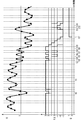
- FIG. 6 is a graph illustrating the operation of this embodiment. More specifically, temporal changes in the reception intensity R, the count value F, and the determination value Q are illustrated.
- the vertical broken line indicates the timing at which step S301 is executed, in other words, the timing at which the reception intensity R and the threshold T are compared.
- the black circles indicate the reception intensity R at that timing.
- the user 2 Before the time t1, the user 2 is kept seated on the seat 3. After the time t1, the user 2 leaves the seat 3 to get off the vehicle, and then leaves the seat (that is, leaves the passenger compartment 40). Along with this, the position of the mobile terminal 20 carried by the user 2 is near the seat 3 until time t1 and moves away from the antenna 101 after time t1. Specifically, a case where the separation distance is maintained before the time t1 regardless of the passage of time and the separation distance increases with the passage of time after the time t1 is exemplified.
- the reception strength R is affected by fading and fluctuates even before time t1. Before time t2, the reception intensity R is larger than the threshold T, but there may be a point in time when the reception intensity R becomes smaller than the threshold T accidentally.
- the count value F (shown by using a thick solid line) transits from the upper limit value 3 to the value 2 (steps S301, S303, S305), but the determination value Q maintains the value 0 (steps S401, S404).
- the reception intensity R exceeds the threshold T and returns to the upper limit value 3 (steps S301 and S304).
- the determination value Q maintains the value 0 (steps S401 and S403).
- step S301 is executed in this order at times t3, t4, t5, t6, t7, t8, t9, and t10.
- the reception intensity R takes a value close to the threshold T and is affected by fading, so the count value F repeats the transition between the value 2 and the upper limit value 3.
- the determination value Q maintains the value 0 by the processing of step S404.
- the reception intensity R continues to be smaller than the threshold value T, and the count value F takes the lower limit value (-3) at the time t11.
- the judgment value Q changes to the value 1.
- the reception strength R is smaller than the threshold T, but there may be a point where the reception strength R accidentally becomes larger than the threshold T.
- the judgment value Q is less affected by fading of the reception strength R and whether or not there is a failure in propagation. Therefore, distance measurement is performed with reduced influence of whether or not fading and propagation are impaired.
- the moving average G of the comparison result of the reception intensity R and the threshold T is also shown by using a thick broken line.
- the moving average G is obtained by considering that the count value F takes a value between the upper limit value 3 and the lower limit value (-3), and the comparison result at the time of the determination and the two comparisons obtained before the time. It is a value obtained by cumulatively adding the results.
- the comparison result is R>T at any time and immediately before that at any time, and the moving average G continues to take the value 3.
- the moving average G takes the value 1, and does not return to the value 3 until two intervals of the determination time point elapses. This indicates that the moving average G is less tolerant of accidental fluctuations as compared with the count value F returning to the upper limit value 3 after one interval has elapsed after the time t0.
- the moving average G repeats the transition between the values 1 and -1.
- the threshold value for performing distance measurement using the moving average G may be set to the value 0. desirable.
- the determination result for the distance measurement from time t3 to t10 is frequently covered and chattering occurs. Further, the moving average G fluctuates more than the count value F with respect to the fluctuation of the reception intensity R from the time t12 to t14, and an erroneous determination occurs from the time t13 in the period of the two intervals.
- the technique using the determination value Q described in the present embodiment is more advantageous than the technique using the moving average G in terms of avoiding erroneous determination of the determination result and/or chattering.
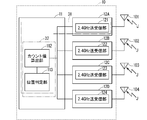
- FIG. 7 is a block diagram illustrating the configuration of the communication device 10.
- FIG. 8 is a block diagram illustrating the configuration of the mobile terminal 20.
- the communication device 10 includes a body control module (body control module) 11 and communication modules (modules) 12A, 12B, 12C, 12D.
- the communication module 12A has a communication unit 121
- the communication module 12B has a communication unit 122
- the communication module 12C has a communication unit 123
- the communication module 12D has a communication unit 124.
- the body control module 11 has a count value calculation unit 112 and a position determination unit 113.
- the communication unit 121 is provided with the antenna 101
- the communication unit 122 is provided with the antenna 102
- the communication unit 123 is provided with the antenna 103
- the communication unit 124 is provided with the antenna 104. Any of the antennas 101 to 104 can receive the signal J.
- the mobile terminal 20 includes a communication unit 21, and the communication unit 21 transmits the signal J as a radio wave via the antenna 20A.
- Each of the communication units 121 to 124 and 21 has a function of transmitting and receiving radio waves in the 2.4 GHz band.
- the communication units 121 to 124 in FIG. 7 and the communication unit 21 in FIG. 8 are all referred to as “2.4 GHz transmission/reception unit”.
- the communication units 121 to 124 and 21 perform transmission/reception based on, for example, Bluetooth Low Energy.
- the antenna 101 is arranged in the passenger room 40.
- Antennas 102-104 may also be located in cabin 40.
- At least one of the communication units 121 to 124 executes step S1 in FIG.
- the step S2 of obtaining the reception intensity R is executed by at least one of the communication units 121 to 124 or the count value calculation unit 112.
- step S1 or steps S1 and S2 are both executed by the communication unit 121.
- Step S3 of calculating the count value F is executed by the count value calculation unit 112.
- the reception intensity R adopted in step S3 not only one communication unit 121 but also the reception intensity R of the signal J obtained in two or more communication units 122 to 124 may be used.
- the communication units 121 to 124 may receive the signal J in parallel, and the maximum value among the reception intensities R of the two or more received signals J may be compared with the threshold value T. Since such a maximum value is not easily affected by fading, such comparison is advantageous from the viewpoint of improving the reliability of distance measurement.
- the position determination unit 113 executes step S4 in which the determination value Q is calculated and steps S5, S6, and S7 in which distance measurement using the determination value Q is performed.
- the separation distance may be viewed as a distance between the communication unit 121 and the mobile terminal 20, or may be viewed as a distance between the passenger compartment 40 and the mobile terminal 20.
- the position determination unit 113 can determine whether the mobile terminal 20 is inside or outside the vehicle, that is, inside or outside the vehicle.
- the count value calculation unit 112, the position determination unit 113, and at least one of the communication units 121 to 124 are combined to measure a distance between itself and the mobile terminal 20. It can be understood as 31.
- the count value calculation unit 112 and the position determination unit 113 can be collectively understood as the control unit 32 that functions as the count value calculation unit 112 and the position determination unit 113.
- the control unit 32 includes a computer including a microprocessor (micro processor), a ROM (Read Only Memory), a RAM (Random Access Memory), and the like.
- a microprocessor micro processor
- ROM Read Only Memory
- RAM Random Access Memory
- An arithmetic processing unit such as a microprocessor stores a computer program (computer program) including some or all of the steps of a flowchart (flow chart) as shown in FIGS. 3, 4, and 5 in a ROM (Read Only Memory). , RAM (Random Access Memory) etc. are read from the respective storage units and executed.
- the computer programs of these multiple devices can be installed from an external server device or the like.
- Such computer programs are in a state of being respectively stored in a recording medium such as a CD-ROM (Compact Disc Read Only Memory), a DVD-ROM (Digital Versatile Disk Only Memory), and a semiconductor memory (memory). Be distributed.
- a recording medium such as a CD-ROM (Compact Disc Read Only Memory), a DVD-ROM (Digital Versatile Disk Only Memory), and a semiconductor memory (memory).
- the determination result of step S301 may be replaced. In this case, only one of the replacement of the determination result of step S5 and the replacement of steps S402 and S403 is involved.
- a process that replaces the above (a) and (b) is: (D) When the count value F takes the upper limit value Fmax, it is determined that the position of the transmission source is away from the antenna 101 by a predetermined distance or more; (E) When the count value F takes the lower limit value Fmin, it is determined that the position is closer than the predetermined distance from the antenna 101.
- the signal J is not limited to the 2.4 GHz band radio wave. Since radio waves with high straightness are easily affected by fading and propagation disturbance, it is useful to apply this embodiment to such radio waves.
Landscapes
- Engineering & Computer Science (AREA)
- Physics & Mathematics (AREA)
- General Physics & Mathematics (AREA)
- Radar, Positioning & Navigation (AREA)
- Remote Sensing (AREA)
- Mechanical Engineering (AREA)
- Mobile Radio Communication Systems (AREA)
- Position Fixing By Use Of Radio Waves (AREA)
Abstract
フェージングおよび伝搬に障害が有るか無いかの影響を低減した測距が行われる。測距装置は、通信部と制御部とを備える。制御部は、信号の受信強度が所定閾値以上のときには上限値を上限としてカウント値を所定値によって増加させ;受信強度が所定閾値未満のときには下限値を下限としてカウント値を所定値によって減少させる。制御部は、カウント値が下限値を採るときには発信源の位置がアンテナから所定値距離以上離れていると判定し;カウント値が上限値を採るときには当該位置がアンテナから所定距離よりも近いと判定し;カウント値が下限値より大きく上限値よりも小さい値を採るときには既に判定された結果を維持する。
Description
本開示は、測距装置に関する。
スマートフォン(smartphone)を用いて、電話回線を介したインターネット(internet)へのアクセス(access)が可能である。インターネットを介して多様な車両情報を取得したり、車両を操作したりすること、例えば車両の開錠および施錠、車両の駆動の開始および停止を、スマートフォンを用いて行う要望が予想される。
通常、車両のユーザ(user)は電子キー(key)を携帯する。当該ユーザが携帯端末(例えばスマートフォン)をも携帯するときには、車両と電子キーとが離れているか否かが、車両と携帯端末とが離れているか否かによって判断され得る。車両から電子キーまでの距離を測定する(つまり測距する)ことによって、車両からユーザが離れているか否かが判断される。
携帯端末に電子キーとしての機能をも担わせ、携帯端末が車内にあるか車外にあるかを判定する技術が提案されている(例えば下記の特許文献1)。例えば携帯端末が車両アンテナから送信された電波の受信強度を測定し、受信強度から携帯端末の位置が車内であるか車外であるかを判定する。
受信強度それ自体はフェージング(fading)や、伝搬に対する障害が有るか無いかの影響を受けやすく、携帯端末の位置について誤判定が生じやすい。
そこで、本開示は、フェージングおよび伝搬に障害が有るか無いかの影響を低減した測距を行う技術を提供することを目的とする。
本開示の測距装置は、少なくとも一つの通信部と、制御部とを備える。前記通信部は発信源から送信された信号を受信する。
前記制御部は、前記通信部が受信した前記信号の受信強度が閾値以上のときには上限値を上限としてカウント値を所定値によって増加させ、前記受信強度が前記閾値未満のときには下限値を下限として前記カウント値を前記所定値によって減少させ、前記カウント値が前記下限値を採るときには前記発信源の位置が前記通信部から所定値距離以上離れていると判定し、前記カウント値が前記上限値を採るときには前記位置が前記通信部から所定距離よりも近いと判定し、前記カウント値が前記下限値より大きく前記上限値よりも小さい値を採るときには既に判定された結果を維持する。
あるいは前記制御部は、前記通信部が受信した前記信号の受信強度が閾値未満のときには上限値を上限としてカウント値を所定値によって増加させ、前記受信強度が前記閾値以上のときには下限値を下限として前記カウント値を前記所定値によって減少させ、前記カウント値が前記上限値を採るときには前記発信源の位置が前記通信部から所定値距離以上離れていると判定し、前記カウント値が前記下限値を採るときには前記位置が前記通信部から所定距離よりも近いと判定し、前記カウント値が前記下限値より大きく前記上限値よりも小さい値を採るときには既に判定された結果を維持する。
本開示は、このような特徴的な処理部を備える測距装置として実現することができるのみならず、かかる特徴的な処理をステップとする測距方法として実現したり、かかるステップ(step)をコンピュータ(computer)に実行させるためのプログラム(program)として実現したりすることができる。また、測距装置の一部又は全部を実現する半導体集積回路として実現したり、測距装置を含む測距システム(system)として実現したりすることができる。
本開示によれば、フェージングおよび伝搬に障害が有るか無いかの影響を低減した測距が行われる。
[本開示の実施形態の説明]
最初に本開示の実施態様が列記して説明される。本開示の測距装置は、少なくとも一つの通信部と、制御部とを備える。前記通信部は発信源から送信された信号を受信する。
最初に本開示の実施態様が列記して説明される。本開示の測距装置は、少なくとも一つの通信部と、制御部とを備える。前記通信部は発信源から送信された信号を受信する。
(1)前記制御部は、前記通信部が受信した前記信号の受信強度が閾値以上のときには上限値を上限としてカウント値を所定値によって増加させ、前記受信強度が前記閾値未満のときには下限値を下限として前記カウント値を前記所定値によって減少させ、前記カウント値が前記下限値を採るときには前記発信源の位置が前記通信部から所定値距離以上離れていると判定し、前記カウント値が前記上限値を採るときには前記位置が前記通信部から所定距離よりも近いと判定し、前記カウント値が前記下限値より大きく前記上限値よりも小さい値を採るときには既に判定された結果を維持する。
例えば前記制御部はカウント値算出部と位置判定部とを有する。前記カウント値算出部は、前記通信部が受信した前記信号の受信強度が閾値以上のときには上限値を上限としてカウント値を所定値によって増加させ、前記受信強度が前記閾値未満のときには下限値を下限として前記カウント値を前記所定値によって減少させる。
前記位置判定部は、前記カウント値が前記下限値を採るときには前記発信源の位置が前記通信部から所定値距離以上離れていると判定し、前記カウント値が前記上限値を採るときには前記位置が前記通信部から所定距離よりも近いと判定し、前記カウント値が前記下限値より大きく前記上限値よりも小さい値を採るときには既に判定された結果を維持する。
本開示によれば、フェージングおよび伝搬に障害が有るか無いかの影響を低減した測距が行われる。
(2)あるいは前記制御部は、前記通信部が受信した前記信号の受信強度が閾値未満のときには上限値を上限としてカウント値を所定値によって増加させ、前記受信強度が前記閾値以上のときには下限値を下限として前記カウント値を前記所定値によって減少させ、前記カウント値が前記上限値を採るときには前記発信源の位置が前記通信部から所定値距離以上離れていると判定し、前記カウント値が前記下限値を採るときには前記位置が前記通信部から所定距離よりも近いと判定し、前記カウント値が前記下限値より大きく前記上限値よりも小さい値を採るときには既に判定された結果を維持する。
例えば前記制御部はカウント値算出部と位置判定部とを有する。前記カウント値算出部は、前記通信部が受信した前記信号の受信強度が閾値未満のときには上限値を上限としてカウント値を所定値によって増加させ、前記受信強度が前記閾値以上のときには下限値を下限として前記カウント値を前記所定値によって減少させる。
前記位置判定部は、前記カウント値が前記上限値を採るときには前記発信源の位置が前記通信部から所定値距離以上離れていると判定し、前記カウント値が前記下限値を採るときには前記位置が前記通信部から所定距離よりも近いと判定し、前記カウント値が前記下限値より大きく前記上限値よりも小さい値を採るときには既に判定された結果を維持する。
本開示によれば、フェージングおよび伝搬に障害が有るか無いかの影響を低減した測距が行われる。
(3)前記通信部は二つ以上設けられ、前記制御部においては、各々の前記通信部が並行して受信した前記信号の前記受信強度の中の最大値が、前記閾値と比較されることが好ましい。測距の信頼度が向上するからである。
例えば前記制御部がカウント値算出部と位置判定部とを有するとき、前記カウント値算出部が、各々の前記通信部が並行して受信した前記信号の前記受信強度の中の最大値を、前記閾値と比較する。
(4)前記通信部は車両に搭載され、前記制御部においては前記発信源が前記車両の内側にあるか外側にあるかが判定されることも好ましい。例えば前記制御部がカウント値算出部と位置判定部とを有するとき、前記位置判定部は前記発信源が前記車両の内側にあるか外側にあるかを判定する。
[本開示の実施形態の詳細]
本開示の測距装置の具体例が、以下に図面を参照して説明される。なお、本開示はこれらの例示に限定されず、請求の範囲によって示され、請求の範囲と均等の意味および範囲内におけるすべての変更が含まれることが意図される。以下に記載される実施形態の少なくとも一部が任意に組み合わせられてもよい。
本開示の測距装置の具体例が、以下に図面を参照して説明される。なお、本開示はこれらの例示に限定されず、請求の範囲によって示され、請求の範囲と均等の意味および範囲内におけるすべての変更が含まれることが意図される。以下に記載される実施形態の少なくとも一部が任意に組み合わせられてもよい。
<全体構成>
図1は、実施形態に係る構成を例示する概念図である。車両の客室40にはアンテナ(antenna)101とシート(seat)3とが配置される。アンテナ101は通信装置10に備えられており、通信装置10は客室40に配置される。通信装置10は車両において客室40以外に配置されてもよい。
図1は、実施形態に係る構成を例示する概念図である。車両の客室40にはアンテナ(antenna)101とシート(seat)3とが配置される。アンテナ101は通信装置10に備えられており、通信装置10は客室40に配置される。通信装置10は車両において客室40以外に配置されてもよい。
ユーザ2は携帯端末20を携帯する。携帯端末20は例えばスマートフォンである。図1においては、ユーザ2がシート3に着座している状態が例示される。
通信装置10はアンテナ101を介して、携帯端末20から電波として発信される信号Jを受信する。信号Jの通信方式としては、例えばIEEE802.15.1の規格に則った通信方法が採用される。信号Jは例えばBluetooth Low Energy(Bluetoothは登録商標)において採用されるアドバタイジング(advertising)信号である。
伝搬経路P11、P12はいずれも、信号Jがアンテナ101において受信されるまでに伝搬する経路を模式的に例示する。伝搬経路P11は携帯端末20からアンテナ101に向けてほぼ直線的な経路であるが、その途中に伝搬の障害となるシート3が介在する場合が例示される。伝搬経路P12は携帯端末20からアンテナ101に向けて客室40の天井(ルーフ:roof)41において反射して伝搬する経路として例示される。
このような伝搬の障害となるシート3の介在は、アンテナ101において受信された信号Jの受信強度を減少させる。しかしユーザ2がシート3から離れればこのような障害は解消し、受信強度は減少されない。よって携帯端末20とアンテナ101との間の距離(以下「離間距離」と仮称)の他、伝搬の障害の有無も受信強度に影響を与える。換言すれば、受信強度それ自体による測距は、伝搬に障害が有るか無いかの影響を受ける。また、異なる伝搬経路P11,P12においてアンテナ101へ伝搬する信号Jの受信強度は、フェージングの影響を受ける。
図2はアンテナ101が受信した信号Jの受信強度Rの、離間距離に対する依存性を模式的に例示するグラフである。携帯端末20が車内にあるときには離間距離が距離Dよりも短く、携帯端末20が車外にあるときには離間距離が距離Dより長い場合が例示される。
閾値Tには、フェージングおよび伝搬の障害の影響がなく、かつ離間距離が距離Dであるときの受信強度Rが採る値が採用できる。このとき、受信強度Rが閾値T未満であれば携帯端末20は車内にあり、受信強度Rが閾値T以上であれば携帯端末20は車外にあると判定される。
値Q1によって例示されるように、フェージングの影響により、離間距離が距離Dよりも短いにも拘らず受信強度Rは大きく低下する。値Q2によって例示されるように、信号Jが伝搬するときにおける障害の影響により、受信強度Rは低下する。
受信強度Rを単に閾値Tと比較することによって離間距離の距離Dに対する長短を判定すると、当該判定はフェージングおよび伝搬の障害の影響を受けてしまう。本実施形態においては受信強度Rに対して下記の処理を行って、離間距離の所定距離に対する長短が判定される。当該所定距離が距離Dに選定されることによって、携帯端末20が車内に位置するか車外に位置するかが判定される。
<本実施形態の処理の流れ>
図3は本実施形態における通信装置10の動作を例示するフローチャートである。ステップS1においては、携帯端末20から送信される信号Jをアンテナ101において受信する処理が行われる。ステップS1の後、ステップS2においては、受信した信号Jの受信強度Rを求める処理が行われる。
図3は本実施形態における通信装置10の動作を例示するフローチャートである。ステップS1においては、携帯端末20から送信される信号Jをアンテナ101において受信する処理が行われる。ステップS1の後、ステップS2においては、受信した信号Jの受信強度Rを求める処理が行われる。
ステップS2の後、ステップS3においてはカウント値Fの算出が行われる。カウント値Fは受信強度Rを所定の閾値Tと比較した結果が累加されてカウントされた値であり、その求め方は後に詳述される。
ステップS3の後、ステップS4においては判定値Qの算出が行われる。判定値Qはカウント値Fに基づいて、離間距離が所定距離よりも短いか否かが判定された結果を示す。閾値Tは所定距離に応じて適宜に決定され得る。判定値Qは値0,1のいずれかを採り、その求め方は後に詳述される。
ステップS4の後、ステップS5においては判定値Qが値0を採るか値1を採るかが判断される。判定値Qが値0を採る場合には信号Jの発信源(ここにおいては携帯端末20)がアンテナ101に対して所定距離内にあると判定される。判定値Qが値1を採る場合には信号Jの発信源(ここにおいては携帯端末20)がアンテナ101に対して所定距離外にあると判定される。ステップS6,S7の判定結果は、所定距離に対する長短によって表わされた、アンテナ101と携帯端末20との間の測距(つまり離間距離の測定)に相当する。離間距離が所定距離よりも長いという測定と、携帯端末20がアンテナ101に対して所定距離外にあるという判定とは同義であるし、離間距離が所定距離よりも短いという測定と、携帯端末20がアンテナ101に対して所定距離内にあるという判定とは同義であるからである。
図4は図3のフローチャートの一部、具体的にはステップS3の詳細を例示するフローチャートであり、カウント値Fの算出を具体的に例示する。ステップS301において受信強度Rが閾値T以上であるか否かが判断される。
上述のように閾値Tは所定距離に応じて適宜に決定され得るものの、フェージングの影響が考慮されるために、ステップS301の判断結果のみによってステップS6,S7の判定に直結させはしない。
ステップS301の判断結果が肯定的であれば、即ち受信強度Rが閾値T以上であれば、ステップS302が実行される。ステップS301の判断結果が否定的であれば、即ち受信強度Rが閾値T未満であれば、ステップS303が実行される。
ステップS302においてはカウント値Fが所定値ΔFによって増加され、ステップS303においてはカウント値Fが所定値ΔFによって減少される。ステップS301,S302の処理により、受信強度Rが閾値T以上であると判断されるほどカウント値Fは増大し、ステップS301,S303の処理により、受信強度Rが閾値T未満であると判断されるほどカウント値Fは減少する。
ステップS302においてカウント値Fが増加される量と、ステップS303においてカウント値Fが減少される量とは必ずしも等しい必要はない。しかしフェージングが受信強度Rに与える影響は増強と低減のいずれであるかによって変動することに鑑みれば、増加する量と減少する量とは等しく設定されることが妥当であると考えられる。よって本実施形態においては当該量は共通して所定値ΔFに設定される。所定値ΔFは例えば値1に選定される。
ステップS302の実行後、ステップS304においてカウント値Fが上限値Fmaxを超えたか否かが判断される。ステップS304の判断結果が肯定的であれば、即ちカウント値Fが上限値Fmaxよりも大きければ、ステップS306においてカウント値Fが上限値Fmaxに設定される。ステップS304の判断結果が否定的であれば、即ちカウント値Fが上限値Fmax以下であれば、ステップS3は終了する。
ステップS304,S306の処理により、ステップS302においてカウント値Fが増加しても上限値Fmaxを超えて増加することが防止される。これは受信強度Rが閾値T未満となる事象が発生したことを、カウント値Fに早期に反映させる観点において有利である。
ステップS303の実行後、ステップS305においてカウント値Fが下限値Fmin未満であるか否かが判断される。ステップS305の判断結果が肯定的であれば、即ちカウント値Fが下限値Fmin未満であれば、ステップS307においてカウント値Fが下限値Fminに設定される。ステップS305の判断結果が否定的であれば、即ちカウント値Fが下限値Fmin以上であれば、ステップS3は終了する。
ステップS305,S307の処理により、ステップS304においてカウント値Fが減少しても下限値Fmin未満に減少することが防止される。これは受信強度Rが閾値T以上となる事象が発生したことを、カウント値Fに早期に反映させる観点において有利である。
図4から、ステップS3の処理は以下のように説明され得る:
(i)受信強度Rが閾値T以上のときには上限値Fmaxを上限としてカウント値Fを所定値ΔFによって増加させ(ステップS302,S304,S306);
(ii)受信強度Rが閾値T未満のときには下限値Fminを下限としてカウント値Fを所定値ΔFによって減少させる(ステップS303,S305,S307)。
(i)受信強度Rが閾値T以上のときには上限値Fmaxを上限としてカウント値Fを所定値ΔFによって増加させ(ステップS302,S304,S306);
(ii)受信強度Rが閾値T未満のときには下限値Fminを下限としてカウント値Fを所定値ΔFによって減少させる(ステップS303,S305,S307)。
図5は図3のフローチャートの一部、具体的にはステップS4の詳細を例示するフローチャートであり、判定値Qの算出を具体的に例示する。ステップS401においてカウント値Fが、下限値Fminおよび上限値Fmaxと比較される。
ステップS401においてカウント値Fが下限値Fminを採ると判断された場合、ステップS402が実行される。ステップS402において判定値Qが値1に設定される。ステップS401においてカウント値Fが上限値Fmaxを採ると判断された場合、ステップS403が実行される。ステップS402において判定値Qが値0に設定される。
カウント値Fが下限値Fminより大きく上限値Fmaxよりも小さい値を採るときにはステップS404が実行される。ステップS404においては既に得られた判定値Qが維持される。このように判定値Qが維持されることは、受信強度Rの偶発的な変動が判定値Qに与える影響が低減される観点において有利である。ステップS404は省略されてもよい。ステップS404は省略されても、ステップS4において得られる判定値Qは影響を受けないからである。
図3が参照され、判定値Qが値0を採るときにステップS6が実行され、判定値Qが値1を採るときにステップS7が実行される。よってステップS4,S5,S6,S7の処理は以下のように説明され得る:
(a)カウント値Fが下限値Fminを採るときには発信源(ここにおいては携帯端末20)の位置がアンテナ101から所定値距離以上離れていると判定し(ステップS402,S7);
(b)カウント値Fが上限値Fmaxを採るときには当該位置がアンテナ101から所定距離よりも近いと判定し(ステップS403,S6);
(c)カウント値Fが下限値Fminより大きく上限値Fmaxよりも小さい値を採るときには既に判定された結果を維持する(ステップS404)。
(a)カウント値Fが下限値Fminを採るときには発信源(ここにおいては携帯端末20)の位置がアンテナ101から所定値距離以上離れていると判定し(ステップS402,S7);
(b)カウント値Fが上限値Fmaxを採るときには当該位置がアンテナ101から所定距離よりも近いと判定し(ステップS403,S6);
(c)カウント値Fが下限値Fminより大きく上限値Fmaxよりも小さい値を採るときには既に判定された結果を維持する(ステップS404)。
<諸量の振る舞い>
図6は本実施形態の動作を例示するグラフである。より具体的には受信強度R、カウント値F、判定値Qの経時的変化が例示される。
図6は本実施形態の動作を例示するグラフである。より具体的には受信強度R、カウント値F、判定値Qの経時的変化が例示される。
縦の破線はステップS301が実行されるタイミング、換言すれば受信強度Rと閾値Tとが比較されるタイミングを示す。黒丸は当該タイミングにおける受信強度Rを示す。
時刻t1以前においてユーザ2はシート3に着座した状態が維持される。時刻t1の後、ユーザ2は降車のため、シート3から離れ、更にその後に車外に出る(つまり客室40から出る)。これに伴い、ユーザ2が携帯する携帯端末20の位置は、時刻t1まではシート3近傍にあり、時刻t1の後にアンテナ101から離れて行く。具体的には時刻t1以前は時間の経過に拘わらずに離間距離は維持され、時刻t1以降においては時間の経過と共に、離間距離は増大する場合が例示される。
受信強度Rはフェージングの影響を受けて、時刻t1以前においても変動する。時刻t2以前においては受信強度Rは閾値Tよりも大きいが、偶発的に受信強度Rが閾値Tよりも小さくなる時点があるかもしれない。
ここにおいて時刻t0(<t1)においてR<Tとなる場合が例示される。時刻t0においてカウント値F(太い実線を用いて示す)は上限値3から値2へ遷移する(ステップS301,S303,S305)が、判定値Qは値0を維持する(ステップS401,S404)。その後に受信強度Rは閾値Tを超え、上限値3へ戻る(ステップS301,S304)。判定値Qは値0を維持する(ステップS401,S403)。
時刻t2の直後において、時刻t3,t4,t5,t6,t7,t8,t9,t10においてはこの順にステップS301が実行される。時刻t2~t10においては受信強度Rが閾値Tに近い値を採り、かつフェージングの影響を受けるので、カウント値Fは値2と上限値3との間の遷移を繰り返す。しかしステップS404の処理により、判定値Qは値0を維持する。
時刻t10の後、受信強度Rは閾値Tよりも小さい期間が続き、時刻t11においてカウント値Fは下限値(-3)を採る。これにより判定値Qは値1へと遷移する。
時刻t11より後においては受信強度Rは閾値Tよりも小さいが、偶発的に受信強度Rが閾値Tよりも大きくなる時点があるかもしれない。
ここにおいて時刻t12(>t11),t13(>t12)においてR≧Tとなる場合が例示される。時刻t12においてカウント値Fは下限値(-3)から値(-1)へ遷移し、時刻t12においてカウント値Fは値(-1)から値1へ遷移するが、ステップS404の処理により、判定値Qは値1を維持する。その後に時刻t14において受信強度Rは閾値T未満となり、下限値(-3)へ戻る。ステップS402の処理により、判定値Qは値1を維持する。
このようにして判定値Qは受信強度Rのフェージングおよび伝搬に障害が有るか無いかの影響から受ける影響が小さい。よってフェージングおよび伝搬に障害が有るか無いかの影響を低減した測距が行われる。
<他の手法に対する優位性>
図6には受信強度Rと閾値Tとの比較結果の移動平均Gが太い破線を用いて併記される。移動平均Gは、カウント値Fが上限値3と下限値(-3)との間の値を採ることに鑑みて、判定する時点の比較結果と、その時点の前に得られた二つの比較結果を累加した値である。
図6には受信強度Rと閾値Tとの比較結果の移動平均Gが太い破線を用いて併記される。移動平均Gは、カウント値Fが上限値3と下限値(-3)との間の値を採ることに鑑みて、判定する時点の比較結果と、その時点の前に得られた二つの比較結果を累加した値である。
例えば時刻t0よりも前には、いずれの時点においてもその時点およびその直前の二つの時点における比較結果はR>Tであり、移動平均Gは値3を採り続ける。しかし時刻t0において受信強度Rが閾値T未満になると移動平均Gは値1を採り、判定する時点の間隔の二つ分が経過するまで値3には戻らない。これはカウント値Fが時刻t0の後、当該間隔の1つ分が経過して上限値3に戻ることと比較して、移動平均Gは偶発的な変動についての耐性が弱いことを示す。
また、時刻t3~t10においては移動平均Gは値1,-1の間の遷移を繰り返す。時刻t0以降において示されるように、偶発的な事象によって値1を採る移動平均Gの振る舞いを考慮すれば、移動平均Gを用いて測距が行われるための閾値は値0とされることが望ましい。
しかしながら値0が移動平均Gのための閾値とされると、時刻t3~t10における測距のための判定結果は、頻繁に覆ってチャタリング(chattering)が発生する。また、時刻t12~t14における受信強度Rの変動に対し、カウント値Fよりも移動平均Gは大きく変動し、時刻t13から上記間隔の二つ分の期間において誤判定が生じてしまう。
従って本実施形態において説明された判定値Qが用いられる技術は、移動平均Gが用いられる手法よりも、判定結果の誤判定、および/またはチャタリングが回避される観点において有利である。
<装置構成>
図7は通信装置10の構成を例示するブロック図である。図8は携帯端末20の構成を例示するブロック図である。
図7は通信装置10の構成を例示するブロック図である。図8は携帯端末20の構成を例示するブロック図である。
通信装置10はボディコントロールモジュール(body control module)11と、通信モジュール(module)12A、12B,12C,12Dとを備える。通信モジュール12Aは通信部121を、通信モジュール12Bは通信部122を、通信モジュール12Cは通信部123を、通信モジュール12Dは通信部124を、それぞれ有する。ボディコントロールモジュール11はカウント値算出部112、位置判定部113を有する。
通信部121にはアンテナ101が、通信部122にはアンテナ102が、通信部123にはアンテナ103が、通信部124にはアンテナ104が、それぞれ設けられる。アンテナ101~104のいずれもが信号Jを受信可能である。
携帯端末20は通信部21を備え、通信部21はアンテナ20Aを介して信号Jを電波として送信する。通信部121~124,21は、いずれも2.4GHz帯の電波を送受信する機能を有する。当該機能に鑑みて、図7においては通信部121~124に、図8においては通信部21に、いずれも「2.4GHz送受信部」と付記される。通信部121~124,21は例えばBluetooth Low Energyに依拠した送受信を行う。
図1によって例示されるように、アンテナ101は客室40に配置される。アンテナ102~104も客室40に配置され得る。
通信部121~124の少なくともいずれか一つは、図3のステップS1を実行する。受信強度Rを求めるステップS2は、通信部121~124の少なくともいずれか一つ、またはカウント値算出部112によって実行される。
図1によって例示されるように、アンテナ101は客室40に配置される。よって図1に即して言えば、ステップS1、またはステップS1,S2のいずれもが通信部121によって実行される。
カウント値Fを算出するステップS3は、カウント値算出部112によって実行される。ステップS3において採用される受信強度Rは、一つの通信部121のみならず、二つ以上の通信部122~124において得られた信号Jの受信強度Rが利用されてもよい。例えば通信部121~124が信号Jを並行して受信し、受信された二つ以上の信号Jの受信強度Rの中の最大値が、閾値Tと比較されてもよい。このような最大値はフェージングの影響を受けにくいので、このような比較は測距の信頼度が向上する観点において有利である。
判定値Qが算出されるステップS4、および判定値Qを用いた測距が行われるステップS5,S6,S7は位置判定部113によって実行される。
通信装置10は車両に搭載されるので、アンテナ101と通信部121とはいずれも車内に設けられる。よって離間距離は通信部121と携帯端末20との間の距離であると見られてもよいし、客室40と携帯端末20との間の距離であると見られてもよい。閾値Tが適宜に設定されることにより、位置判定部113は携帯端末20が車内にあるか車外にあるか、即ち車両の内側にあるか、外側にあるかを判定することができる。
カウント値算出部112と、位置判定部113と、通信部121~124の少なくとも一つ(例えば通信部121)とは纏めて、自身と携帯端末20との間の距離を測距する測距装置31と理解され得る。
カウント値算出部112と位置判定部113とは纏めて、カウント値算出部112と位置判定部113との機能を果たす制御部32と理解され得る。
制御部32は、マイクロプロセッサ(micro processor)、ROM(Read Only Memory)、RAM(Random Access Memory)等を含み構成されるコンピュータを備える。
マイクロプロセッサ等の演算処理部は、図3、図4、図5に示すようなフローチャート(flow chart)の各ステップの一部または全部を含むコンピュータプログラム(computer program)を、ROM(Read Only Memory)、RAM(Random Access Memory)等の記憶部からそれぞれ読み出して実行する。
これら複数の装置のコンピュータプログラムは、それぞれ、外部のサーバ(server)装置等からインストール(install)されることができる。
また、このようなコンピュータプログラムは、それぞれ、CD-ROM(Compact Disc Read Only Memory)、DVD-ROM(Digital Versatile Disk Read Only Memory)、半導体メモリ(memory)等の記録媒体に格納された状態にあって流通する。
{変形例}
第1実施形態において、ステップS301の判断結果が入れ替えられてもよい。この場合、ステップS5の判断結果の入替えと、ステップS402,S403同士の入替えとのいずれか一方のみが伴われる。
第1実施形態において、ステップS301の判断結果が入れ替えられてもよい。この場合、ステップS5の判断結果の入替えと、ステップS402,S403同士の入替えとのいずれか一方のみが伴われる。
つまり上記(i)(ii)に代わる処理は:
(iii)受信強度Rが閾値T未満のときには上限値Fmaxを上限としてカウント値Fを所定値ΔFによって増加させ;
(iv)受信強度Rが閾値T以上のときには下限値Fminを下限としてカウント値Fを所定値ΔFによって減少させる。
(iii)受信強度Rが閾値T未満のときには上限値Fmaxを上限としてカウント値Fを所定値ΔFによって増加させ;
(iv)受信強度Rが閾値T以上のときには下限値Fminを下限としてカウント値Fを所定値ΔFによって減少させる。
そして上記(c)を維持しつつ、上記(a)(b)に代わる処理は:
(d)カウント値Fが上限値Fmaxを採るときには発信源の位置がアンテナ101から所定値距離以上離れていると判定し;
(e)カウント値Fが下限値Fminを採るときには当該位置がアンテナ101から所定距離よりも近いと判定する。
(d)カウント値Fが上限値Fmaxを採るときには発信源の位置がアンテナ101から所定値距離以上離れていると判定し;
(e)カウント値Fが下限値Fminを採るときには当該位置がアンテナ101から所定距離よりも近いと判定する。
本実施形態において信号Jは2.4GHz帯の電波に限定されない。直進性が高い電波はフェージングや伝搬障害の影響を受けやすいので、かかる電波に対して本実施形態を適用することは有益である。
なお、上記実施形態および各変形例において説明された各構成は、相互に矛盾しない限り適宜組み合わせられ得る。
2 ユーザ
3 シート
10 通信装置
11 ボディコントロールモジュール
12A,12B,12C,12D 通信モジュール
20 携帯端末
20A,101,102,103,104 アンテナ
21,121,122,123,124 通信部
31 測距装置
32 制御部
40 客室
112 カウント値算出部
113 位置判定部
D 距離
F カウント値
Fmax 上限値
Fmin 下限値
G 移動平均
J 信号
P11,P12 伝搬経路
Q 判定値
R 受信強度
S1~S7,S301~S307,S401~S404 ステップ
T 閾値
t0~t14 時刻
ΔF 所定値
3 シート
10 通信装置
11 ボディコントロールモジュール
12A,12B,12C,12D 通信モジュール
20 携帯端末
20A,101,102,103,104 アンテナ
21,121,122,123,124 通信部
31 測距装置
32 制御部
40 客室
112 カウント値算出部
113 位置判定部
D 距離
F カウント値
Fmax 上限値
Fmin 下限値
G 移動平均
J 信号
P11,P12 伝搬経路
Q 判定値
R 受信強度
S1~S7,S301~S307,S401~S404 ステップ
T 閾値
t0~t14 時刻
ΔF 所定値
Claims (4)
- 少なくとも一つの通信部と、
制御部と
を備え、
前記通信部は発信源から送信された信号を受信し、
前記制御部は、
前記通信部が受信した前記信号の受信強度が閾値以上のときには上限値を上限としてカウント値を所定値によって増加させ、前記受信強度が前記閾値未満のときには下限値を下限として前記カウント値を前記所定値によって減少させ、前記カウント値が前記下限値を採るときには前記発信源の位置が前記通信部から所定値距離以上離れていると判定し、前記カウント値が前記上限値を採るときには前記位置が前記通信部から所定距離よりも近いと判定し、前記カウント値が前記下限値より大きく前記上限値よりも小さい値を採るときには既に判定された結果を維持する、測距装置。 - 少なくとも一つの通信部と、
制御部と
を備え、
前記通信部は発信源から送信された信号を受信し、
前記制御部は、
前記通信部が受信した前記信号の受信強度が閾値未満のときには上限値を上限としてカウント値を所定値によって増加させ、前記受信強度が前記閾値以上のときには下限値を下限として前記カウント値を前記所定値によって減少させ、前記カウント値が前記上限値を採るときには前記発信源の位置が前記通信部から所定値距離以上離れていると判定し、前記カウント値が前記下限値を採るときには前記位置が前記通信部から所定距離よりも近いと判定し、前記カウント値が前記下限値より大きく前記上限値よりも小さい値を採るときには既に判定された結果を維持する、測距装置。 - 請求項1または請求項2に記載の測距装置であって、
前記通信部は二つ以上設けられ、
前記制御部においては、各々の前記通信部が並行して受信した前記信号の前記受信強度の中の最大値が、前記閾値と比較される、測距装置。 - 請求項1、請求項2または請求項3に記載の測距装置であって、
前記通信部は車両に搭載され、
前記制御部においては前記発信源が前記車両の内側にあるか外側にあるかが判定される、測距装置。
Applications Claiming Priority (2)
| Application Number | Priority Date | Filing Date | Title |
|---|---|---|---|
| JP2018246750A JP2020106451A (ja) | 2018-12-28 | 2018-12-28 | 測距装置 |
| JP2018-246750 | 2018-12-28 |
Publications (1)
| Publication Number | Publication Date |
|---|---|
| WO2020137753A1 true WO2020137753A1 (ja) | 2020-07-02 |
Family
ID=71129733
Family Applications (1)
| Application Number | Title | Priority Date | Filing Date |
|---|---|---|---|
| PCT/JP2019/049652 Ceased WO2020137753A1 (ja) | 2018-12-28 | 2019-12-18 | 測距装置 |
Country Status (2)
| Country | Link |
|---|---|
| JP (1) | JP2020106451A (ja) |
| WO (1) | WO2020137753A1 (ja) |
Citations (4)
| Publication number | Priority date | Publication date | Assignee | Title |
|---|---|---|---|---|
| JPH07186643A (ja) * | 1993-12-28 | 1995-07-25 | Sumitomo Electric Ind Ltd | タイヤ空気圧低下検出装置およびこの装置における警報発生/停止方法 |
| JP2007124466A (ja) * | 2005-10-31 | 2007-05-17 | Matsushita Electric Ind Co Ltd | ダイバーシティシステム及びそのプログラム |
| JP2010060457A (ja) * | 2008-09-04 | 2010-03-18 | Tokai Rika Co Ltd | 位置判定装置 |
| JP2014206495A (ja) * | 2013-04-15 | 2014-10-30 | 株式会社デンソー | 携帯端末の位置検出装置 |
-
2018
- 2018-12-28 JP JP2018246750A patent/JP2020106451A/ja active Pending
-
2019
- 2019-12-18 WO PCT/JP2019/049652 patent/WO2020137753A1/ja not_active Ceased
Patent Citations (4)
| Publication number | Priority date | Publication date | Assignee | Title |
|---|---|---|---|---|
| JPH07186643A (ja) * | 1993-12-28 | 1995-07-25 | Sumitomo Electric Ind Ltd | タイヤ空気圧低下検出装置およびこの装置における警報発生/停止方法 |
| JP2007124466A (ja) * | 2005-10-31 | 2007-05-17 | Matsushita Electric Ind Co Ltd | ダイバーシティシステム及びそのプログラム |
| JP2010060457A (ja) * | 2008-09-04 | 2010-03-18 | Tokai Rika Co Ltd | 位置判定装置 |
| JP2014206495A (ja) * | 2013-04-15 | 2014-10-30 | 株式会社デンソー | 携帯端末の位置検出装置 |
Also Published As
| Publication number | Publication date |
|---|---|
| JP2020106451A (ja) | 2020-07-09 |
Similar Documents
| Publication | Publication Date | Title |
|---|---|---|
| US8706120B2 (en) | Mobile telecommunication system with adaptive handoff mechanism and method of operation thereof | |
| TW201713129A (zh) | 專用短程通訊(dsrc)中的安全事件訊息傳輸定時 | |
| US20180176841A1 (en) | Switching between network media based on connection quality | |
| JP2008107281A (ja) | レーダ装置 | |
| CN112896183B (zh) | 车辆故障判断设备和方法 | |
| US11999294B2 (en) | Vehicle and control method thereof | |
| CN104025666B (zh) | 用于显著增强无线连接的可用性的方法 | |
| CN114125846B (zh) | 完好性保护方法和系统 | |
| US11307578B2 (en) | Manual drive changing notification apparatus and method of vehicle and vehicle including the same | |
| WO2020137753A1 (ja) | 測距装置 | |
| US10624011B2 (en) | Switching between network media seamlessly while maintaining a network connection | |
| WO2020137725A1 (ja) | 測距装置 | |
| JP2009064329A (ja) | 先頭車両判定装置 | |
| Zhang et al. | On the usefulness of spectrum prediction for dynamic spectrum access | |
| JP2007529942A (ja) | 無線通信装置 | |
| JP2010081128A (ja) | キャリアセンス方法及びキャリアセンス装置 | |
| US20220029744A1 (en) | Control device, communication device, and system | |
| JP2020022120A (ja) | 電子装置及び通信方法 | |
| US10873487B1 (en) | Communication device, method for predicting interruption, control circuit, and program recording medium | |
| US10750426B1 (en) | Systems and methods for adaptively joining a wireless communication network | |
| JP2020176917A (ja) | 車載装置 | |
| US9466193B2 (en) | Device and method for detecting intrusion | |
| JP2019528436A (ja) | 距離測定方法および距離測定装置 | |
| JP2016217710A (ja) | 列車位置検知装置、及び方法 | |
| WO2020137751A1 (ja) | 測距装置、通信装置、通信システム |
Legal Events
| Date | Code | Title | Description |
|---|---|---|---|
| 121 | Ep: the epo has been informed by wipo that ep was designated in this application |
Ref document number: 19902794 Country of ref document: EP Kind code of ref document: A1 |
|
| NENP | Non-entry into the national phase |
Ref country code: DE |
|
| 122 | Ep: pct application non-entry in european phase |
Ref document number: 19902794 Country of ref document: EP Kind code of ref document: A1 |