WO2020137625A1 - ロボットハンド - Google Patents
ロボットハンド Download PDFInfo
- Publication number
- WO2020137625A1 WO2020137625A1 PCT/JP2019/048946 JP2019048946W WO2020137625A1 WO 2020137625 A1 WO2020137625 A1 WO 2020137625A1 JP 2019048946 W JP2019048946 W JP 2019048946W WO 2020137625 A1 WO2020137625 A1 WO 2020137625A1
- Authority
- WO
- WIPO (PCT)
- Prior art keywords
- motor
- link
- robot hand
- gripping force
- drive link
- Prior art date
- Legal status (The legal status is an assumption and is not a legal conclusion. Google has not performed a legal analysis and makes no representation as to the accuracy of the status listed.)
- Ceased
Links
Images



Classifications
-
- B—PERFORMING OPERATIONS; TRANSPORTING
- B25—HAND TOOLS; PORTABLE POWER-DRIVEN TOOLS; MANIPULATORS
- B25J—MANIPULATORS; CHAMBERS PROVIDED WITH MANIPULATION DEVICES
- B25J15/00—Gripping heads and other end effectors
- B25J15/08—Gripping heads and other end effectors having finger members
Definitions
- the present invention relates to a robot hand that holds an object.
- Grasping is an action of giving an action such as pinching to lift a work when an object (hereinafter referred to as a work) is transported using a robot hand, for example.
- a robot hand generally, the rotation operation of a drive source (motor or the like) is converted into a finger gripping opening/closing operation using a link mechanism or the like.
- this robot hand has a large gripping force in order to lift a heavier work.
- a robot hand having a worm gear as a power transmission mechanism is known (see, for example, Patent Document 1).
- the worm gear has a self-locking function and can rotate the input side from the input side, but cannot rotate the input side from the output side. Therefore, in this robot hand, the fingers do not naturally move in the opening direction, and it is possible to realize a large gripping force while reducing the size and weight.
- the present invention has been made to solve the above problems, and in a robot hand using a power transmission mechanism having a self-locking function, a robot hand capable of feedback control according to a force applied from the outside. Is intended to provide.
- a robot hand has a motor and four links including a drive link driven by the motor, and transmits one or more four-link mechanism and the power of the motor to the drive link.
- a power transmission mechanism having a self-locking function and a displacement sensor provided on any one of the links of one or more of the link mechanisms for detecting displacement, and a grip based on a detection result of the displacement sensor.
- the present invention is characterized by including a gripping force detection unit that calculates a force and a control unit that controls a motor based on a calculation result by the gripping force detection unit.
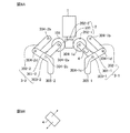
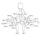
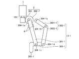
- FIG. 1A is a schematic diagram showing a configuration example of the robot hand according to the first embodiment
- FIG. 1B is a diagram showing displacement detected by a displacement sensor in FIG. 1A
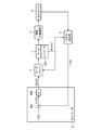
- 3 is a block diagram showing a configuration example of the robot hand according to the first embodiment.
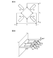
- FIG. 3A and 3B are diagrams showing a configuration example (full bridge circuit) and an arrangement example of the displacement sensor according to the first embodiment of the present invention.
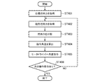
- 6 is a flowchart showing an example of gripping force control (target tracking control) by the gripping force detection unit and the controller in the first embodiment.
- 7 is a flowchart showing an example of gripping force control (external force tracking control) by the gripping force detection unit and the controller in the first embodiment.
- FIG. 6A is a schematic diagram showing another configuration example of the robot hand according to the first embodiment of the present invention
- FIG. 6B is a diagram showing displacement detected by the displacement sensor in FIG. 6A.
- It is a schematic diagram which shows another structural example of the robot hand which concerns on Embodiment 1 of this invention.
- It is a schematic diagram which shows the structural example of the robot hand which concerns on Embodiment 2 of this invention.
- Embodiment 1. 1 and 2 are diagrams showing a configuration example of the robot hand according to the first embodiment.
- the robot hand grips a work (not shown).
- the robot hand includes a motor 1, at least one worm gear (power transmission mechanism) 2, at least one link mechanism 3, at least one displacement sensor 4, and a gripping force detection unit 5.
- the gripping force detection unit 5, the controller 6, and the motor driver 7 are not shown.
- the worm gear 2 and the link mechanism 3 form a drive transmission mechanism 8.
- the motor 1 is a drive source for generating a gripping force on the robot hand.
- the output shaft 101 of the motor 1 is a single shaft, and the motor 1 outputs the rotation by the output shaft 101. Further, as shown in FIG. 2, the motor 1 has an encoder 102 that detects the rotation angle of the motor 1.
- Worm gear 2 has a self-locking function and transmits the power of motor 1 to link mechanism 3.
- FIG. 1 shows a case where the robot hand has one worm gear 2.
- the worm gear 2 shown in FIG. 1 has a worm 201 connected to the output shaft 101 of the motor 1, a worm wheel 202-1 screwed to the worm 201, and a worm wheel 202-2 screwed to the worm 201. ..
- the motor 1 and the worm gear 2 are connected in series.
- the invention is not limited to this, and a bevel gear may be provided between the motor 1 and the worm gear 2, for example.
- the link mechanism 3 is a 4-section link mechanism.
- FIG. 1 shows a case where the robot hand has two link mechanisms 3-1 and 3-2. When the robot hand has only one link mechanism 3, the robot hand uses this link mechanism 3 and a fixing member such as a wall to grip a work.
- the link mechanism 3-1 has a drive link 301-1, an angle holding link 302-1 and a driven link 303-1.
- the drive link 301-1 has one end connected to the worm wheel 202-1 via a hinge pin (rotating shaft) 304-1a.
- the drive link 301-1 is driven by the motor 1, and the swing amount (angle, speed, torque, etc.) at one end is controlled according to the rotation of the output shaft 101.
- the one end of the angle holding link 302-1 is rotatably connected to the main body of the robot hand via a hinge pin 304-1b.
- the other end of the drive link 301-1 is rotatably connected via a hinge pin 304-1c, and the other end of the angle holding link 302-1 is rotatably connected via a hinge pin 304-1d.
- the finger 305-1 is connected to one end.
- the driven link 303-1 moves integrally with the finger 305-1.
- the drive link 301-1 is rotatably connected to one end side (finger 305-1 side) of the driven link 303-1 and the angle holding link 302-1 rotates to the other end side of the driven link 303-1. Connected freely.
- the link mechanism 3-2 has a drive link 301-2, an angle holding link 302-2, and a driven link 303-2.
- the drive link 301-2 has one end connected to the worm wheel 202-2 via a hinge pin (rotating shaft) 304-2a.
- the drive link 301-2 is driven by the motor 1, and the swing amount (angle, speed, torque, etc.) at one end is controlled according to the rotation of the output shaft 101.
- the one end of the angle holding link 302-2 is rotatably connected to the main body of the robot hand via a hinge pin 304-2b.
- the other end of the drive link 301-2 is rotatably connected via a hinge pin 304-2c, and the other end of the angle holding link 302-2 is rotatably connected via a hinge pin 304-2d.
- the finger 305-2 is connected to one end.
- the follower link 303-2 moves integrally with the finger 305-2.
- the drive link 301-2 is rotatably connected to one end side (finger 305-2 side) of the driven link 303-2, and the angle holding link 302-2 rotates to the other end side of the driven link 303-2. Connected freely.
- the displacement sensor 4 is provided on the drive link 301 in one or more link mechanisms 3 and detects displacement of an attached part (electrical output (resistance value, capacitance, voltage or current, etc. according to displacement). Output)).
- the displacement sensor 4 is attached to each of two opposing side surfaces of the drive link 301-1 (two side surfaces in a direction perpendicular to the rotation axis direction of the drive link 301-1) to detect displacement due to a bending moment. This shows the case (see FIG. 1B).
- the displacement sensor 4 is composed of, for example, a metal strain gauge. Further, for example, as shown in FIG. 3B, by attaching four metal strain gauges (R1 to R4) as the displacement sensor 4 and forming a full bridge circuit (Wheatstone bridge circuit) as shown in FIG. The strain components other than the bending moment can be removed, temperature compensation, etc. can be performed, and high accuracy can be achieved.
- E represents the applied voltage
- E o represents the output voltage.
- the displacement sensor 4 may be attached to each of the two or more side surfaces of the drive link 301-1 for the reason described above, but only one may be attached to one side surface. It does not change.
- the displacement sensor 4 may be composed of, for example, a semiconductor strain gauge.
- the semiconductor strain gauge is realized by MEMS (Micro Electro Mechanical Systems).
- the gripping force detection unit 5 calculates the gripping force of the robot hand based on the detection result of the encoder 102 and the detection result of the displacement sensor 4. Since the robot hand shown in FIG. 1 uses the link mechanism 3, the value detected by the displacement sensor 4 with respect to the gripping force of the robot hand changes depending on the link angle. Therefore, the gripping force detection unit 5 calculates the gripping force of the robot hand by correcting the displacement detected by the displacement sensor 4 according to the rotation angle of the motor 1 detected by the encoder 102. In FIG. 2, ⁇ M [rad] indicates the rotation angle of the motor 1, and F s [N] indicates the current gripping force of the robot hand.
- the gripping force detection unit 5 is realized by a processing circuit such as a system LSI (Large Scale Integration) or a CPU (Central Processing Unit) that executes a program stored in a memory or the like.
- the gripping force detection unit 5 may calculate the gripping force of the robot hand based on only the detection result of the displacement sensor 4 without using the detection result of the encoder 102. However, in this case, the calculation accuracy by the gripping force detection unit 5 is low because the error due to the link angle is large, and the force control accuracy is low.
- the controller 6 calculates the command angle for the motor 1 based on the calculation result by the gripping force detection unit 5.
- the controller 6 is realized by a processing circuit such as a system LSI, or a CPU that executes a program stored in a memory or the like. As shown in FIG. 2, the controller 6 has a subtracting unit 601 and a coefficient multiplying unit 602.
- the subtraction unit 601 subtracts the grip force of the robot hand calculated by the grip force detection unit 5 from the target grip force of the robot hand to obtain a difference value.
- F r [N] indicates the target gripping force of the robot hand
- ⁇ F [N] indicates the difference value.
- the coefficient multiplying unit 602 obtains the command angle for the motor 1 by multiplying the difference value obtained by the subtracting unit 601 by the coefficient (K f ).
- ⁇ r [rad] indicates a command angle.
- the coefficient used by the coefficient multiplying unit 602 is a positive value when the controller 6 performs target tracking control as gripping force control, and a negative value when the controller 6 performs external force tracking control as gripping force control.
- the target follow-up control is control for making the gripping force of the robot hand follow the target gripping force.
- the external force follow-up control is a control in which the gripping force of the robot hand is made to follow so that the external force applied to the robot hand becomes zero.
- the motor driver 7 controls the motor 1 by PID control or the like based on the detection result of the encoder 102 and the calculation result of the controller 6. At this time, the motor driver 7 controls the motor 1 so that the rotation angle of the motor 1 detected by the encoder 102 matches the command angle calculated by the controller 6.
- the motor driver 7 is realized by a processing circuit such as a system LSI, a CPU that executes a program stored in a memory, or the like.
- controller 6 and the motor driver 7 configure a “control unit that controls the motor 1 based on the calculation result of the gripping force detection unit 5”.
- the controller 6 first acquires the target gripping force of the robot hand set by the user (step ST401).
- the gripping force detection unit 5 calculates the current gripping force of the robot hand based on the rotation angle of the motor 1 detected by the encoder 102 and the displacement detected by the displacement sensor 4 (step ST402).
- the subtraction unit 601 subtracts the grip force of the robot hand calculated by the grip force detection unit 5 from the target grip force of the robot hand acquired by the controller 6 to obtain a difference value (step ST403).
- the coefficient multiplying unit 602 is multiplied by a factor (K f) with respect to the difference value obtained by the subtraction unit 601, to obtain a command angle for the motor 1 (step ST 404).
- K f a factor
- the above coefficient is a positive value.
- the controller 6 outputs a signal indicating the command angle obtained by the coefficient multiplying unit 602 to the motor driver 7 (step ST405).
- the motor driver 7 controls the motor 1 so that the rotation angle of the motor 1 detected by the encoder 102 matches the command angle.
- step ST406 determines whether or not there is a next operation command.
- the controller 6 determines in step ST406 that there is no next operation command, the sequence returns to step ST402. As a result, the robot hand operates so that the gripping force becomes the target gripping force.
- step ST406 when it is determined that there is a next operation command, the controller 6 ends the target tracking control and executes the next operation command.
- the gripping force detection unit 5 detects the robot based on the rotation angle of the motor 1 detected by the encoder 102 and the displacement detected by the displacement sensor 4.
- the current gripping force of the hand is calculated (step ST501).
- the controller 6 sets the current gripping force of the robot hand calculated by the gripping force detection unit 5 as the target gripping force (step ST502).
- the gripping force detection unit 5 calculates the current gripping force of the robot hand based on the rotation angle of the motor 1 detected by the encoder 102 and the displacement detected by the displacement sensor 4 (step ST503).
- the subtraction unit 601 subtracts the grip force of the robot hand calculated by the grip force detection unit 5 from the target grip force of the robot hand set by the controller 6 to obtain a difference value (step ST504).
- the coefficient multiplying unit 602 obtains a command angle for the motor 1 by multiplying the difference value obtained by the subtracting unit 601 by a coefficient (K f ) (step ST505).
- the coefficient is a negative value.
- the controller 6 outputs a signal indicating the command angle obtained by the coefficient multiplying unit 602 to the motor driver 7 (step ST506).
- the motor driver 7 controls the rotation angle of the motor 1 detected by the encoder 102 to match the command angle.
- step ST507 determines whether or not there is a next operation command. If the controller 6 determines in step ST507 that there is no next operation command, the sequence returns to step ST503. As a result, the robot hand operates so that the external force applied to the finger 305 becomes zero. On the other hand, in step ST507, when the controller 6 determines that there is a next operation command, the controller 6 ends the external force tracking control and executes the next operation command.
- the robot hand thus configured, for example, when a worker applies a force to the finger 305 in the opening direction while gripping a work, the force is detected as a displacement by the displacement sensor 4. Then, in this robot hand, the displacement detected by the displacement sensor 4 is fed back as a command angle to the motor driver 7 via the grip force detection unit 5 and the controller 6. As a result, the robot hand can move the finger 305 in the opening direction according to the force applied by the operator. When the user does not apply a force to the finger 305, the external force is 0, so the command angle for the motor 1 is 0. Therefore, in this robot hand, it is not necessary to send a position control command from the controller 6 or to move the input side of the worm gear 2 by mechanical means when releasing the gripped work, unlike the conventional configuration.
- the displacement sensor 4 detects the displacement due to the bending moment.
- the present invention is not limited to this, and the displacement sensor 4 may detect displacement due to shearing force (see FIG. 6B).
- the displacement sensor 4 is attached to two opposing side surfaces of the drive link 301-1 (two side surfaces in the rotation axis direction of the drive link 301-1), as shown in FIG. 6A, for example.
- the angle holding link 302 is arranged outside the drive link 301 is shown.
- the invention is not limited to this, and the angle holding link 302 may be arranged inside the drive link 301.
- the case where the output shaft 101 of the motor 1 is a single shaft is shown.
- the present invention is not limited to this, and the output shaft 101 of the motor 1 may be both shafts.
- FIG. 7 shows a case where the angle holding link 302 is arranged inside the drive link 301 and the output shaft 101 is both shafts.
- FIG. 7 shows a case where the output shaft 101 of the motor 1 is a double shaft and the motor 1 outputs the rotation by the output shafts 101-1 and 101-2.
- the robot hand has two worm gears 2-1 and 2-2.
- the worm gear 2-1 has a worm 201-1 connected to the output shaft 101-1 of the motor 1, and a worm wheel 202-1 screwed to the worm 201-1.
- the worm gear 2-2 has a worm 201-2 connected to the output shaft 101-2 of the motor 1 and a worm wheel 202-2 screwed to the worm 201-2.
- the drive link 301-1 shown in FIG. 7 has one end connected to the worm wheel 202-1 via a hinge pin 304-1a.
- the drive link 301-1 is driven by the motor 1, and the swing amount (angle, speed, torque, etc.) at one end is controlled according to the rotation of the output shaft 101-1.
- the angle holding link 302-1 is rotatably connected to one end side (finger 305-1 side) of the driven link 303-1 and the drive link 301-1 is connected to the other end side of the driven link 303-1. It is rotatably connected.
- the drive link 301-2 shown in FIG. 7 has one end connected to the worm wheel 202-2 via a hinge pin 304-2a.
- the drive link 301-2 is driven by the motor 1, and the swing amount (angle, speed, torque, etc.) at one end is controlled according to the rotation of the output shaft 101-2.
- the angle holding link 302-2 is rotatably connected to one end side (finger 305-2 side) of the driven link 303-2, and the drive link 301-2 is connected to the other end side of the driven link 303-2. It is rotatably connected.
- the effect and principle of the robot hand shown in FIG. 7 are the same as the effect and principle of the robot hand shown in FIGS.
- the displacement sensor 4 detects the displacement due to the bending moment, but the displacement sensor 4 may detect the displacement due to the shearing force.
- the mounting location of the displacement sensor 4 is the same as in FIG. 6A.
- the output shaft 101 and the rotation axis of the drive link 301 are configured to be orthogonal (including the meaning of substantially orthogonal) is shown.
- the present invention is not limited to this, and a spur gear or the like may be used so that the output shaft 101 and the rotation shaft of the drive link 301 are parallel (including substantially parallel meaning).
- the displacement sensor 4 is provided on the drive link 301 .
- the present invention is not limited to this, and the displacement sensor 4 may be provided on the angle holding link 302 or the driven link 303.
- the displacement sensor 4 is provided on the link (the drive link 301-1 in FIGS. 1, 6 and 7) in one link mechanism 3 is shown.
- the present invention is not limited to this, and the displacement sensor 4 may also be provided in the links of some or all of the other link mechanisms 3.
- the accuracy of detecting the gripping force of the robot hand is improved.
- FIG. 1 shows a case where the worm gear 2 is used as the power transmission mechanism.
- the power transmission mechanism is not limited to this, and may be any mechanism having a self-locking function.
- a parallel slider mechanism including a trapezoidal screw 9 connected to the output shaft 101 of the motor 1 and a parallel slider 10 screwed onto the trapezoidal screw 9 may be used as the power transmission mechanism.
- the drive link 301 is composed of two links 3011 and 3012 that are rotatably connected in series.
- the drive link 301-1 has a link 3011-1 whose one end is rotatably connected to the parallel slider 10 via a hinge pin 304-1a and the other end of the link 3011-1 whose one end is via a hinge pin 304-1e. And a link 3012-1 rotatably connected to.
- the drive link 301-2 has a link 3011-2, one end of which is rotatably connected to the parallel slider 10 via a hinge pin 304-2a, and the other end of the link 3011-2, whose one end is via a hinge pin 304-2e.
- a link 3012-2 rotatably connected to.
- a cam may be used as the power transmission mechanism.
- the robot hand has four links including the motor 1 and the drive link 301 driven by the motor 1, and one or more four-section links are provided.
- a mechanism 3 a power transmission mechanism having a self-locking function for transmitting the power of the motor 1 to the drive link 301, and a displacement sensor provided in any one of the links of one or more link mechanisms 3 for detecting a displacement.
- a gripping force detection unit 5 that calculates the gripping force based on the detection result of the displacement sensor 4
- a control unit that controls the motor 1 based on the calculation result of the gripping force detection unit 5.
- Embodiment 2 In the robot hand according to the first embodiment, the case where the link mechanism 3 of Section 4 is used is shown. On the other hand, the robot hand may use the link mechanism 3 having five or more joints.
- the angle holding link 302 is configured by a plurality (M) of links rotatably connected in series to configure the link mechanism 3 of (4+M) nodes. Good.
- the angle holding link 302-1 has a link 3021-1 whose one end is rotatably connected to the main body of the robot hand through a hinge pin 304-1b, and one end which is connected through a hinge pin 304-1f. 1 and the link 3022-1 which is rotatably connected to the other end.
- FIG. 9 the angle holding link 302 is configured by a plurality (M) of links rotatably connected in series to configure the link mechanism 3 of (4+M) nodes.
- the angle holding link 302-1 has a link 3021-1 whose one end is rotatably connected to the main body of the robot hand through a hinge pin
- FIG. 9 shows a case where the drive link 301 is arranged inside the angle holding link 302 and the output shaft 101 is a single shaft, but the point that the configuration is not limited to this is the same as in the first embodiment. Is. Further, when the angle holding link 302 is composed of a plurality of links, a lock mechanism is provided at the hinge portion of each link so that the link is not rotated by an external force when the robot hand grips the work. Need to be done.
- the displacement sensor 4 is provided on the drive link 301 in one or more link mechanisms 3.
- the motor 1 outputs the rotation by the output shaft 101 .
- the present invention is not limited to this, and the motor 1 may perform a linear motion output.
- the power of the motor 1 is not limited to electric power, and may be air or hydraulic type, for example.
- the robot hand according to the present invention is a robot hand using a power transmission mechanism having a self-locking function, which enables feedback control according to a force applied from the outside, and is suitable for use in a robot hand that grips an object. ing.
Landscapes
- Engineering & Computer Science (AREA)
- Robotics (AREA)
- Mechanical Engineering (AREA)
- Manipulator (AREA)
Abstract
モータ(1)と、モータ(1)により駆動される駆動リンク(301)を含む4つのリンクを有し、1つ以上設けられた4節のリンク機構(3)と、モータ(1)の動力を駆動リンク(301)に伝達する、セルフロック機能を有する動力伝達機構と、1つ以上のリンク機構(3)におけるリンクのうちの何れかに設けられ、変位を検出する変位センサ(4)と、変位センサ(4)による検出結果に基づいて、把持力を算出する把持力検出部(5)と、把持力検出部(5)による算出結果に基づいて、モータ(1)を制御する制御部とを備えた。
Description
この発明は、対象物を把持するロボットハンドに関する。
ロボットハンドが有する機能の一つとして「把持機能」がある。把持とは、例えばロボットハンドを用いて対象物(以降、ワークと称す)を運搬する際に、ワークを持ち上げるために挟み込み等の作用をワークに与える行為である。
ロボットハンドでは、一般的に、駆動源(モータ等)の回転動作を、リンク機構等を用いてフィンガの把持開閉動作に変換している。
ロボットハンドでは、一般的に、駆動源(モータ等)の回転動作を、リンク機構等を用いてフィンガの把持開閉動作に変換している。
このロボットハンドは、より重いワークを持ち上げるため、大きな把持力を有することが望ましい。しかしながら、従来のロボットハンドでは、把持力を大きくするためには、モータのトルクを大きくする必要があった。
これに対し、動力伝達機構としてウォームギアを備えたロボットハンドが知られている(例えば特許文献1参照)。ウォームギアは、セルフロック機能を有し、入力側から出力側を回転させることができるが、出力側からは入力側を回転させることができない。そのため、このロボットハンドでは、フィンガが自然には開方向には動かず、小型化及び軽量化しつつ大きな把持力を実現可能である。
上述したように、ウォームギアを用いたロボットハンドでは、ワークを保持しているフィンガに力を加えてもウォームギアの入力側には力が伝わらない。よって、このロボットハンドでは、セルフロック機能を有していない動力伝達機構を用いたロボットハンドのように、フィンガに加えた力は動力伝達機構を介してモータに伝えられず、モータ電流変化によるフィードバック制御を実施できない。そのため、このロボットハンドでは、把持したワークを解放する際には、コントローラから位置制御指令を送る、又は、機械的手段によりウォームギアの入力側を動かす必要があった。
この発明は、上記のような課題を解決するためになされたもので、セルフロック機能を有する動力伝達機構を用いたロボットハンドにおいて、外部から加えられた力に応じてフィードバック制御が可能なロボットハンドを提供することを目的としている。
この発明に係るロボットハンドは、モータと、モータにより駆動される駆動リンクを含む4つのリンクを有し、1つ以上設けられた4節のリンク機構と、モータの動力を駆動リンクに伝達する、セルフロック機能を有する動力伝達機構と、リンク機構のうちの1つ以上のリンク機構におけるリンクのうちの何れかに設けられ、変位を検出する変位センサと、変位センサによる検出結果に基づいて、把持力を算出する把持力検出部と、把持力検出部による算出結果に基づいて、モータを制御する制御部とを備えたことを特徴とする。
この発明によれば、上記のように構成したので、セルフロック機能を有する動力伝達機構を用いたロボットハンドにおいて、外部から加えられた力に応じてフィードバック制御が可能である。
以下、この発明の実施の形態について図面を参照しながら詳細に説明する。
実施の形態1.
図1,2は実施の形態1に係るロボットハンドの構成例を示す図である。
ロボットハンドは、ワーク(不図示)を把持する。このロボットハンドは、図1,2に示すように、モータ1、1つ以上のウォームギア(動力伝達機構)2、1つ以上のリンク機構3、1つ以上の変位センサ4、把持力検出部5、コントローラ6及びモータドライバ7を備えている。なお図1では、把持力検出部5、コントローラ6及びモータドライバ7の図示を省略している。また、ウォームギア2及びリンク機構3は駆動伝達機構8を構成する。また以下では、同一の構成要素が複数系統存在する場合には、その構成要素を示す符号に系統毎の接尾記号(-1,-2,・・・)を付すものとし、また、特に区別する必要がない場合には接尾記号を付さずに説明を行う。
実施の形態1.
図1,2は実施の形態1に係るロボットハンドの構成例を示す図である。
ロボットハンドは、ワーク(不図示)を把持する。このロボットハンドは、図1,2に示すように、モータ1、1つ以上のウォームギア(動力伝達機構)2、1つ以上のリンク機構3、1つ以上の変位センサ4、把持力検出部5、コントローラ6及びモータドライバ7を備えている。なお図1では、把持力検出部5、コントローラ6及びモータドライバ7の図示を省略している。また、ウォームギア2及びリンク機構3は駆動伝達機構8を構成する。また以下では、同一の構成要素が複数系統存在する場合には、その構成要素を示す符号に系統毎の接尾記号(-1,-2,・・・)を付すものとし、また、特に区別する必要がない場合には接尾記号を付さずに説明を行う。
モータ1は、ロボットハンドに把持力を発生させるための駆動源である。図1では、モータ1が有する出力軸101が単軸であり、モータ1が出力軸101により回転出力を行う場合を示している。また、図2に示すように、モータ1は、モータ1の回転角度を検出するエンコーダ102を有する。
ウォームギア2は、セルフロック機能を有し、モータ1の動力をリンク機構3に伝達する。図1では、ロボットハンドが1つのウォームギア2を有する場合を示している。図1に示すウォームギア2は、モータ1が有する出力軸101に接続されたウォーム201と、ウォーム201に螺合したウォームホイール202-1と、ウォーム201に螺合したウォームホイール202-2とを有する。
なお図1では、モータ1とウォームギア2とが直列接続されている。しかしながら、これに限らず、例えば、モータ1とウォームギア2との間に傘歯ギアを設けてもよい。
リンク機構3は、4節のリンク機構である。図1では、ロボットハンドが2つのリンク機構3-1,3-2を有する場合を示している。
なお、ロボットハンドが1つのリンク機構3のみを有する場合には、ロボットハンドはこのリンク機構3と壁等の固定部材を用いてワークの把持を行う。
なお、ロボットハンドが1つのリンク機構3のみを有する場合には、ロボットハンドはこのリンク機構3と壁等の固定部材を用いてワークの把持を行う。
リンク機構3-1は、駆動リンク301-1、角度保持リンク302-1及び従動リンク303-1を有する。
駆動リンク301-1は、一端がヒンジピン(回転軸)304-1aを介してウォームホイール202-1に接続されている。この駆動リンク301-1は、モータ1により駆動され、出力軸101の回転に応じて一端の揺動量(角度、速度又はトルク等)が制御される。
角度保持リンク302-1は、一端が、ヒンジピン304-1bを介して、ロボットハンドの本体に回転自在に接続されている。
従動リンク303-1は、駆動リンク301-1の他端がヒンジピン304-1cを介して回転自在に連結され、角度保持リンク302-1の他端がヒンジピン304-1dを介して回転自在に連結され、一端にフィンガ305-1が連結されている。この従動リンク303-1は、フィンガ305-1と一体に連動して運動する。図1では、駆動リンク301-1は従動リンク303-1の一端側(フィンガ305-1側)に回転自在に接続され、角度保持リンク302-1は従動リンク303-1の他端側に回転自在に接続されている。
リンク機構3-2は、駆動リンク301-2、角度保持リンク302-2及び従動リンク303-2を有する。
駆動リンク301-2は、一端がヒンジピン(回転軸)304-2aを介してウォームホイール202-2に接続されている。この駆動リンク301-2は、モータ1により駆動され、出力軸101の回転に応じて一端の揺動量(角度、速度又はトルク等)が制御される。
角度保持リンク302-2は、一端が、ヒンジピン304-2bを介して、ロボットハンドの本体に回転自在に接続されている。
従動リンク303-2は、駆動リンク301-2の他端がヒンジピン304-2cを介して回転自在に連結され、角度保持リンク302-2の他端がヒンジピン304-2dを介して回転自在に連結され、一端にフィンガ305-2が連結されている。この従動リンク303-2は、フィンガ305-2と一体に連動して運動する。図1では、駆動リンク301-2は従動リンク303-2の一端側(フィンガ305-2側)に回転自在に接続され、角度保持リンク302-2は従動リンク303-2の他端側に回転自在に接続されている。
変位センサ4は、1つ以上のリンク機構3における駆動リンク301に設けられ、取付けられた部位の変位を検出する(変位に応じた電気的な出力(抵抗値、静電容量、電圧又は電流等の出力)を行う)。図1では、変位センサ4が、駆動リンク301-1の対向する2つの側面(駆動リンク301-1の回転軸方向に垂直な方向における2つの側面)にそれぞれ取付けられ、曲げモーメントによる変位を検出する場合を示している(図1B参照)。
なお、変位センサ4は、例えば金属歪ゲージから構成される。また、例えば図3Bのように、変位センサ4として4個の金属歪ゲージ(R1~R4)を貼り、図3Aのようにフルブリッジ回路(ホイートストンブリッジ回路)を構成することで、変位センサ4は、曲げモーメント以外の歪成分の除去及び温度補償等を行うことができ、高精度化が可能である。なお図3Aにおいて、Eは印加電圧を表し、Eoは出力電圧を表す。
なお、変位センサ4は、上記に示す理由により駆動リンク301-1の2つ以上の側面にそれぞれ取付けられる場合もあるが、1つの側面に1つのみ取付けられてもよく、本発明の本質を変更するものではない。
なお、変位センサ4は、上記に示す理由により駆動リンク301-1の2つ以上の側面にそれぞれ取付けられる場合もあるが、1つの側面に1つのみ取付けられてもよく、本発明の本質を変更するものではない。
また、変位センサ4は、例えば半導体歪ゲージから構成されてもよい。半導体歪ゲージは、MEMS(Micro Electro Mechanical Systems)により実現される。
把持力検出部5は、エンコーダ102による検出結果及び変位センサ4による検出結果に基づいて、ロボットハンドの把持力を算出する。図1に示すロボットハンドでは、リンク機構3を用いているため、ロボットハンドの把持力に対する変位センサ4による検出値がリンク角度によって変化する。そこで、把持力検出部5は、エンコーダ102により検出されたモータ1の回転角度に応じて変位センサ4により検出された変位を補正して、ロボットハンドの把持力を算出する。図2において、θM[rad]はモータ1の回転角度を示し、Fs[N]はロボットハンドの現在の把持力を示す。なお、把持力検出部5は、システムLSI(Large Scale Integration)等の処理回路、又はメモリ等に記憶されたプログラムを実行するCPU(Central Processing Unit)等により実現される。
なお、把持力検出部5は、エンコーダ102による検出結果を用いずに、変位センサ4による検出結果のみに基づいて、ロボットハンドの把持力を算出してもよい。但し、この場合、把持力検出部5による算出精度はリンク角度による誤差が大きくなるため低くなり、力制御精度は低くなる。
コントローラ6は、把持力検出部5による算出結果に基づいて、モータ1に対する指令角度を算出する。なお、コントローラ6は、システムLSI等の処理回路、又はメモリ等に記憶されたプログラムを実行するCPU等により実現される。このコントローラ6は、図2に示すように、減算部601及び係数乗算部602を有している。
減算部601は、ロボットハンドの目標把持力から把持力検出部5により算出されたロボットハンドの把持力を減算して差分値を得る。図2において、Fr[N]はロボットハンドの目標把持力を示し、ΔF[N]は差分値を示す。
係数乗算部602は、減算部601により得られた差分値に対して係数(Kf)を乗算することで、モータ1に対する指令角度を得る。図2において、θr[rad]は指令角度を示す。なお、係数乗算部602が用いる係数は、コントローラ6が把持力制御として目標追従制御を行う場合には正の値であり、コントローラ6が把持力制御として外力追従制御を行う場合には負の値である。目標追従制御とは、ロボットハンドの把持力を目標把持力に追従させる制御である。また、外力追従制御とは、ロボットハンドの把持力を、ロボットハンドに加えられた外力を0とするように追従させる制御である。
モータドライバ7は、エンコーダ102による検出結果及びコントローラ6による算出結果に基づいて、PID制御等により、モータ1を制御する。この際、モータドライバ7は、エンコーダ102により検出されたモータ1の回転角度をコントローラ6により算出された指令角度に一致させるようにモータ1を制御する。なお、モータドライバ7は、システムLSI等の処理回路、又はメモリ等に記憶されたプログラムを実行するCPU等により実現される。
なお、コントローラ6及びモータドライバ7は、「把持力検出部5による算出結果に基づいて、モータ1を制御する制御部」を構成する。
次に、図2に示す把持力検出部5及びコントローラ6による把持力制御(目標追従制御)の一例について、図4を参照しながら説明する。
把持力検出部5及びコントローラ6が目標追従制御を開始すると、まず、コントローラ6は、ユーザにより設定されたロボットハンドの目標把持力を取得する(ステップST401)。
把持力検出部5及びコントローラ6が目標追従制御を開始すると、まず、コントローラ6は、ユーザにより設定されたロボットハンドの目標把持力を取得する(ステップST401)。
次いで、把持力検出部5は、エンコーダ102により検出されたモータ1の回転角度及び変位センサ4により検出された変位に基づいて、ロボットハンドの現在の把持力を算出する(ステップST402)。
次いで、減算部601は、コントローラ6が取得したロボットハンドの目標把持力から把持力検出部5により算出されたロボットハンドの把持力を減算して差分値を得る(ステップST403)。
次いで、係数乗算部602は、減算部601により得られた差分値に対して係数(Kf)を乗算することで、モータ1に対する指令角度を得る(ステップST404)。なお、上記係数は正の値である。
次いで、コントローラ6は、係数乗算部602により得られた指令角度を示す信号をモータドライバ7に出力する(ステップST405)。その後、モータドライバ7は、エンコーダ102により検出されたモータ1の回転角度を上記指令角度に一致させるようにモータ1を制御する。
次いで、コントローラ6は、次の動作指令があるかを判定する(ステップST406)。このステップST406において、コントローラ6が次の動作指令が無いと判定した場合には、シーケンスはステップST402に戻る。これにより、ロボットハンドは把持力が目標把持力となるように動作する。
一方、ステップST406において、コントローラ6は、次の動作指令があると判定した場合には、目標追従制御を終了して次の動作指令を実行する。
一方、ステップST406において、コントローラ6は、次の動作指令があると判定した場合には、目標追従制御を終了して次の動作指令を実行する。
次に、図2に示す把持力検出部5及びコントローラ6による把持力制御(外力追従制御)の一例について、図5を参照しながら説明する。上述したように、ロボットハンドではウォームギア2のセルフロック機能によりウォームギア2の出力側からは入力側に力が伝わらない。一方、実施の形態1に係るロボットハンドでは、変位センサ4により検出された変位を把持力検出部5及びコントローラ6を介してモータドライバ7に指令角度としてフィードバックすることで、ユーザがフィンガ305を掴んで自由に開閉可能となる。
把持力検出部5及びコントローラ6が外力追従制御を開始すると、まず、把持力検出部5は、エンコーダ102により検出されたモータ1の回転角度及び変位センサ4により検出された変位に基づいて、ロボットハンドの現在の把持力を算出する(ステップST501)。
把持力検出部5及びコントローラ6が外力追従制御を開始すると、まず、把持力検出部5は、エンコーダ102により検出されたモータ1の回転角度及び変位センサ4により検出された変位に基づいて、ロボットハンドの現在の把持力を算出する(ステップST501)。
次いで、コントローラ6は、把持力検出部5により算出されたロボットハンドの現在の把持力を、目標把持力に設定する(ステップST502)。
次いで、把持力検出部5は、エンコーダ102により検出されたモータ1の回転角度及び変位センサ4により検出された変位に基づいて、ロボットハンドの現在の把持力を算出する(ステップST503)。
次いで、減算部601は、コントローラ6が設定したロボットハンドの目標把持力から把持力検出部5により算出されたロボットハンドの把持力を減算して差分値を得る(ステップST504)。
次いで、係数乗算部602は、減算部601により得られた差分値に対して係数(Kf)を乗算することで、モータ1に対する指令角度を得る(ステップST505)。なお、上記係数は負の値である。
次いで、コントローラ6は、係数乗算部602により得られた指令角度を示す信号をモータドライバ7に出力する(ステップST506)。その後、モータドライバ7は、エンコーダ102により検出されたモータ1の回転角度を上記指令角度に一致させるように制御する。
次いで、コントローラ6は、次の動作指令があるかを判定する(ステップST507)。このステップST507において、コントローラ6が次の動作指令が無いと判定した場合には、シーケンスはステップST503に戻る。これにより、ロボットハンドはフィンガ305に加えられた外力を0とするように動作する。
一方、ステップST507において、コントローラ6は、次の動作指令があると判定した場合には、外力追従制御を終了して次の動作指令を実行する。
一方、ステップST507において、コントローラ6は、次の動作指令があると判定した場合には、外力追従制御を終了して次の動作指令を実行する。
このように構成されたロボットハンドでは、例えばワークを把持した状態で作業者がフィンガ305に対して開方向に力を加えた場合、その力が変位センサ4により変位として検出される。そして、このロボットハンドでは、変位センサ4により検出された変位が把持力検出部5及びコントローラ6を介してモータドライバ7に指令角度としてフィードバックされる。その結果、このロボットハンドは、作業者により加えられた上記力に応じて、フィンガ305を開方向に動かすことができる。なお、ユーザがフィンガ305に力を加えていない場合には、外力は0であるため、モータ1に対する指令角度は0となる。よって、このロボットハンドでは、従来構成のように、把持したワークを解放する際に、コントローラ6から位置制御指令を送る、又は、機械的手段によりウォームギア2の入力側を動かす必要はない。
なお上記では、変位センサ4が曲げモーメントによる変位を検出する場合を示した。しかしながら、これに限らず、変位センサ4はせん断力による変位を検出してもよい(図6B参照)。この場合、変位センサ4は、例えば図6Aに示すように、駆動リンク301-1の対向する2つの側面(駆動リンク301-1の回転軸方向における2つの側面)にそれぞれ取付けられる。
また上記では、角度保持リンク302が駆動リンク301より外側に配置された場合を示した。しかしながら、これに限らず、角度保持リンク302は駆動リンク301より内側に配置されてもよい。
また上記では、モータ1の出力軸101が単軸である場合を示した。しかしながら、これに限らず、モータ1の出力軸101は両軸でもよい。
また上記では、モータ1の出力軸101が単軸である場合を示した。しかしながら、これに限らず、モータ1の出力軸101は両軸でもよい。
例えば図7では、角度保持リンク302が駆動リンク301より内側に配置され、且つ、出力軸101が両軸である場合を示している。
図7では、モータ1が有する出力軸101が両軸であり、モータ1が出力軸101-1,101-2により回転出力を行う場合を示している。
図7では、モータ1が有する出力軸101が両軸であり、モータ1が出力軸101-1,101-2により回転出力を行う場合を示している。
この場合、図7に示すように、ロボットハンドが2つのウォームギア2-1,2-2を有する。
ウォームギア2-1は、モータ1が有する出力軸101-1に接続されたウォーム201-1と、ウォーム201-1に螺合したウォームホイール202-1とを有する。
ウォームギア2-2は、モータ1が有する出力軸101-2に接続されたウォーム201-2と、ウォーム201-2に螺合したウォームホイール202-2とを有する。
ウォームギア2-1は、モータ1が有する出力軸101-1に接続されたウォーム201-1と、ウォーム201-1に螺合したウォームホイール202-1とを有する。
ウォームギア2-2は、モータ1が有する出力軸101-2に接続されたウォーム201-2と、ウォーム201-2に螺合したウォームホイール202-2とを有する。
また、図7に示す駆動リンク301-1は、一端がヒンジピン304-1aを介してウォームホイール202-1に接続されている。この駆動リンク301-1は、モータ1により駆動され、出力軸101-1の回転に応じて、一端の揺動量(角度、速度又はトルク等)が制御される。
また図7では、角度保持リンク302-1は従動リンク303-1の一端側(フィンガ305-1側)に回転自在に接続され、駆動リンク301-1は従動リンク303-1の他端側に回転自在に接続されている。
また図7では、角度保持リンク302-1は従動リンク303-1の一端側(フィンガ305-1側)に回転自在に接続され、駆動リンク301-1は従動リンク303-1の他端側に回転自在に接続されている。
同様に、図7に示す駆動リンク301-2は、一端がヒンジピン304-2aを介してウォームホイール202-2に接続されている。この駆動リンク301-2は、モータ1により駆動され、出力軸101-2の回転に応じて、一端の揺動量(角度、速度又はトルク等)が制御される。
また図7では、角度保持リンク302-2は従動リンク303-2の一端側(フィンガ305-2側)に回転自在に接続され、駆動リンク301-2は従動リンク303-2の他端側に回転自在に接続されている。
また図7では、角度保持リンク302-2は従動リンク303-2の一端側(フィンガ305-2側)に回転自在に接続され、駆動リンク301-2は従動リンク303-2の他端側に回転自在に接続されている。
その他の構成は図1,2に示すロボットハンドと同様であり、その説明を省略する。また、図7に示すロボットハンドの効果及び原理についても、図1,2に示すロボットハンドの効果及び原理と同様である。
なお図7に示すロボットハンドでは、変位センサ4が曲げモーメントによる変位を検出する場合を示しているが、変位センサ4はせん断力による変位を検出してもよい。この場合、変位センサ4の取付け箇所は図6Aと同様である。
なお図7に示すロボットハンドでは、変位センサ4が曲げモーメントによる変位を検出する場合を示しているが、変位センサ4はせん断力による変位を検出してもよい。この場合、変位センサ4の取付け箇所は図6Aと同様である。
また上記では、出力軸101と駆動リンク301の回転軸とが直交(略直交の意味を含む)するように構成された場合を示した。しかしながら、これに限らず、平歯車等を用いて、出力軸101と駆動リンク301の回転軸とが平行(略平行の意味を含む)となるように構成されてもよい。
また上記では、変位センサ4が駆動リンク301に設けられた場合を示した。しかしながら、これに限らず、変位センサ4が角度保持リンク302又は従動リンク303に設けられていてもよい。
また上記では、変位センサ4は、1つのリンク機構3におけるリンク(図1,6,7では駆動リンク301-1)に設けられた場合を示した。しかしながら、これに限らず、変位センサ4は、他の一部又は全部のリンク機構3におけるリンクにも設けられていてもよい。このように、複数のリンク機構3に変位センサ4を設けることで、ロボットハンドは把持力の検出精度が向上する。
なお上記では、ロボットハンドが外径把持を行う場合について説明を行ったが、ロボットハンドが内径把持を行う場合についても同様である。
また図1では、動力伝達機構としてウォームギア2を用いた場合を示した。しかしながら、これに限らず、動力伝達機構はセルフロック機能を有する機構であればよい。
例えば図8に示すように、動力伝達機構として、モータ1が有する出力軸101に接続された台形ネジ9と、当該台形ネジ9に螺合した平行スライダ10とから成る平行スライダ機構を用いてもよい。この場合、図8に示すように、駆動リンク301は回転自在に直列接続された2つのリンク3011,3012から構成される。すなわち、駆動リンク301-1は、一端がヒンジピン304-1aを介して平行スライダ10に回転自在に接続されたリンク3011-1と、一端がヒンジピン304-1eを介してリンク3011-1の他端に回転自在に接続されたリンク3012-1とから構成される。また、駆動リンク301-2は、一端がヒンジピン304-2aを介して平行スライダ10に回転自在に接続されたリンク3011-2と、一端がヒンジピン304-2eを介してリンク3011-2の他端に回転自在に接続されたリンク3012-2とから構成される。
また、動力伝達機構として、カムを用いてもよい。
例えば図8に示すように、動力伝達機構として、モータ1が有する出力軸101に接続された台形ネジ9と、当該台形ネジ9に螺合した平行スライダ10とから成る平行スライダ機構を用いてもよい。この場合、図8に示すように、駆動リンク301は回転自在に直列接続された2つのリンク3011,3012から構成される。すなわち、駆動リンク301-1は、一端がヒンジピン304-1aを介して平行スライダ10に回転自在に接続されたリンク3011-1と、一端がヒンジピン304-1eを介してリンク3011-1の他端に回転自在に接続されたリンク3012-1とから構成される。また、駆動リンク301-2は、一端がヒンジピン304-2aを介して平行スライダ10に回転自在に接続されたリンク3011-2と、一端がヒンジピン304-2eを介してリンク3011-2の他端に回転自在に接続されたリンク3012-2とから構成される。
また、動力伝達機構として、カムを用いてもよい。
以上のように、この実施の形態1によれば、ロボットハンドは、モータ1と、モータ1により駆動される駆動リンク301を含む4つのリンクを有し、1つ以上設けられた4節のリンク機構3と、モータ1の動力を駆動リンク301に伝達する、セルフロック機能を有する動力伝達機構と、1つ以上のリンク機構3におけるリンクのうちの何れかに設けられ、変位を検出する変位センサ4と、変位センサ4による検出結果に基づいて、把持力を算出する把持力検出部5と、把持力検出部5による算出結果に基づいてモータ1を制御する制御部とを備えた。これにより、実施の形態1に係るロボットハンドは、外部から加えられた力に応じてフィードバック制御が可能である。
また、実施の形態1に係るロボットハンドでは、作業者がフィンガ305を掴んで開閉動作を行うダイレクト教示を実施可能である。
実施の形態2.
実施の形態1に係るロボットハンドでは、4節のリンク機構3を用いた場合を示した。これに対し、ロボットハンドは、5節以上のリンク機構3を用いてもよい。具体的には、例えば図9に示すように、角度保持リンク302を回転自在に直列接続された複数(M個)のリンクから構成することで、(4+M)節のリンク機構3を構成してもよい。図9では、角度保持リンク302-1は、一端がヒンジピン304-1bを介してロボットハンドの本体に回転自在に接続されたリンク3021-1と、一端がヒンジピン304-1fを介してリンク3021-1の他端に回転自在に接続されたリンク3022-1とから構成されている。なお図9では、ウォームホイール202-2及びリンク機構3-2の図示は省略している。また図9では、駆動リンク301が角度保持リンク302より内側に配置され、且つ、出力軸101が単軸である場合を示しているが、構成がこれに限らない点は実施の形態1と同様である。
また、角度保持リンク302が複数のリンクから構成される場合、各リンクのヒンジ部分には、ロボットハンドがワークの把持を行う場合に、外力によってリンクが回転してしまわないようにロック機構が設けられる必要がある。
実施の形態1に係るロボットハンドでは、4節のリンク機構3を用いた場合を示した。これに対し、ロボットハンドは、5節以上のリンク機構3を用いてもよい。具体的には、例えば図9に示すように、角度保持リンク302を回転自在に直列接続された複数(M個)のリンクから構成することで、(4+M)節のリンク機構3を構成してもよい。図9では、角度保持リンク302-1は、一端がヒンジピン304-1bを介してロボットハンドの本体に回転自在に接続されたリンク3021-1と、一端がヒンジピン304-1fを介してリンク3021-1の他端に回転自在に接続されたリンク3022-1とから構成されている。なお図9では、ウォームホイール202-2及びリンク機構3-2の図示は省略している。また図9では、駆動リンク301が角度保持リンク302より内側に配置され、且つ、出力軸101が単軸である場合を示しているが、構成がこれに限らない点は実施の形態1と同様である。
また、角度保持リンク302が複数のリンクから構成される場合、各リンクのヒンジ部分には、ロボットハンドがワークの把持を行う場合に、外力によってリンクが回転してしまわないようにロック機構が設けられる必要がある。
なお、ロボットハンドが5節以上のリンク機構3を有する場合には、変位センサ4は、1つ以上のリンク機構3における駆動リンク301に設けられる。
また、実施の形態1,2に係るロボットハンドでは、モータ1が出力軸101により回転出力を行う場合を示した。しかしながら、これに限らず、モータ1は直動出力を行ってもよい。また、モータ1の動力は、電動に限らず、例えばエア又は油圧式であってもよい。
なお、本願発明はその発明の範囲内において、各実施の形態の自由な組合わせ、或いは各実施の形態の任意の構成要素の変形、若しくは各実施の形態において任意の構成要素の省略が可能である。
この発明に係るロボットハンドは、セルフロック機能を有する動力伝達機構を用いたロボットハンドにおいて、外部から加えられた力に応じてフィードバック制御が可能となり、対象物を把持するロボットハンドに用いるのに適している。
1 モータ
2 ウォームギア
3 リンク機構
4 変位センサ
5 把持力検出部
6 コントローラ
7 モータドライバ
8 駆動伝達機構
9 台形ネジ
10 平行スライダ
101 出力軸
102 エンコーダ
201 ウォーム
202 ウォームホイール
301 駆動リンク
302 角度保持リンク
303 従動リンク
304 ヒンジピン
305 フィンガ
601 減算部
602 係数乗算部
3011,3012 リンク
3021,3022 リンク
2 ウォームギア
3 リンク機構
4 変位センサ
5 把持力検出部
6 コントローラ
7 モータドライバ
8 駆動伝達機構
9 台形ネジ
10 平行スライダ
101 出力軸
102 エンコーダ
201 ウォーム
202 ウォームホイール
301 駆動リンク
302 角度保持リンク
303 従動リンク
304 ヒンジピン
305 フィンガ
601 減算部
602 係数乗算部
3011,3012 リンク
3021,3022 リンク
Claims (12)
- モータと、
前記モータにより駆動される駆動リンクを含む4つのリンクを有し、1つ以上設けられた4節のリンク機構と、
前記モータの動力を前記駆動リンクに伝達する、セルフロック機能を有する動力伝達機構と、
前記リンク機構のうちの1つ以上のリンク機構における前記リンクのうちの何れかに設けられ、変位を検出する変位センサと、
前記変位センサによる検出結果に基づいて、把持力を算出する把持力検出部と、
前記把持力検出部による算出結果に基づいて、前記モータを制御する制御部と
を備えたロボットハンド。 - 前記モータの回転角度を検出するエンコーダを備え、
前記把持力検出部は、前記エンコーダによる検出結果及び前記変位センサによる検出結果に基づいて、把持力を算出し、
前記制御部は、
前記把持力検出部による算出結果に基づいて、前記モータに対する指令角度を算出するコントローラと、
前記エンコーダによる検出結果及び前記コントローラによる算出結果に基づいて、前記モータを制御するモータドライバとを有する
ことを特徴とする請求項1記載のロボットハンド。 - 前記コントローラは、
目標把持力から前記把持力検出部により算出された把持力を減算して差分値を得る減算部と、
前記減算部により得られた差分値に対して係数を乗算することで、前記モータに対する指令角度を得る係数乗算部とを有し、
前記モータドライバは、前記エンコーダにより検出された回転角度を前記コントローラにより算出された指令角度に一致させるように前記モータを制御する
ことを特徴とする請求項2記載のロボットハンド。 - 前記動力伝達機構は、ウォームギアである
ことを特徴とする請求項1から請求項3のうちの何れか1項記載のロボットハンド。 - 前記動力伝達機構は、台形ネジ及び当該台形ネジに螺合した平行スライダから成る平行スライダ機構であり、
前記駆動リンクは、回転自在に直列接続された2つのリンクから成る
ことを特徴とする請求項1から請求項3のうちの何れか1項記載のロボットハンド。 - 前記駆動リンクは、一端が前記モータにより駆動される回転軸に接続され、
前記リンク機構は各々、
一端が回転自在に本体に接続された角度保持リンクと、
前記駆動リンクの他端及び前記角度保持リンクの他端が回転自在に接続され、一端にフィンガが連結された従動リンクとを有する
ことを特徴とする請求項1から請求項5のうちの何れか1項記載のロボットハンド。 - モータと、
前記モータにより駆動される駆動リンクを含む複数のリンクを有し、1つ以上設けられた5節以上のリンク機構と、
前記モータの動力を前記駆動リンクに伝達する、セルフロック機能を有する動力伝達機構と、
前記リンク機構のうちの1つ以上のリンク機構における前記駆動リンクに設けられ、変位を検出する変位センサと、
前記変位センサによる検出結果に基づいて、把持力を算出する把持力検出部と、
前記把持力検出部による算出結果に基づいて、前記モータを制御する制御部と
を備えたロボットハンド。 - 前記モータの回転角度を検出するエンコーダを備え、
前記把持力検出部は、前記エンコーダによる検出結果及び前記変位センサによる検出結果に基づいて、把持力を算出し、
前記制御部は、
前記把持力検出部による算出結果に基づいて、前記モータに対する指令角度を算出するコントローラと、
前記エンコーダによる検出結果及び前記コントローラによる算出結果に基づいて、前記モータを制御するモータドライバとを有する
ことを特徴とする請求項7記載のロボットハンド。 - 前記コントローラは、
目標把持力から前記把持力検出部により算出された把持力を減算して差分値を得る減算部と、
前記減算部により得られた差分値に対して係数を乗算することで、前記モータに対する指令角度を得る係数乗算部とを有し、
前記モータドライバは、前記エンコーダにより検出された回転角度を前記コントローラにより算出された指令角度に一致させるように前記モータを制御する
ことを特徴とする請求項8記載のロボットハンド。 - 前記動力伝達機構は、ウォームギアである
ことを特徴とする請求項7から請求項9のうちの何れか1項記載のロボットハンド。 - 前記動力伝達機構は、台形ネジ及び当該台形ネジに螺合した平行スライダから成る平行スライダ機構であり、
前記駆動リンクは、回転自在に直列接続された2つのリンクから成る
ことを特徴とする請求項7から請求項9のうちの何れか1項記載のロボットハンド。 - 前記駆動リンクは、一端が前記モータにより駆動される回転軸に接続され、
前記リンク機構は各々、
回転自在に直列接続された複数のリンクから成り、一端が回転自在に本体に接続された角度保持リンクと、
前記駆動リンクの他端及び前記角度保持リンクの他端が回転自在に接続され、一端にフィンガが連結された従動リンクとを有する
ことを特徴とする請求項7から請求項11のうちの何れか1項記載のロボットハンド。
Applications Claiming Priority (2)
| Application Number | Priority Date | Filing Date | Title |
|---|---|---|---|
| JP2018-244652 | 2018-12-27 | ||
| JP2018244652A JP2020104203A (ja) | 2018-12-27 | 2018-12-27 | ロボットハンド |
Publications (1)
| Publication Number | Publication Date |
|---|---|
| WO2020137625A1 true WO2020137625A1 (ja) | 2020-07-02 |
Family
ID=71129025
Family Applications (1)
| Application Number | Title | Priority Date | Filing Date |
|---|---|---|---|
| PCT/JP2019/048946 Ceased WO2020137625A1 (ja) | 2018-12-27 | 2019-12-13 | ロボットハンド |
Country Status (2)
| Country | Link |
|---|---|
| JP (1) | JP2020104203A (ja) |
| WO (1) | WO2020137625A1 (ja) |
Cited By (3)
| Publication number | Priority date | Publication date | Assignee | Title |
|---|---|---|---|---|
| CN115107074A (zh) * | 2022-08-05 | 2022-09-27 | 上海非夕机器人科技有限公司 | 夹持装置、机器人以及力信息感测方法 |
| WO2024026805A1 (en) | 2022-08-05 | 2024-02-08 | Shanghai Flexiv Robotics Technology Co., Ltd. | Gripping device, robot and method for sensing force information |
| CN115107074B (en) * | 2022-08-05 | 2026-05-05 | 上海非夕机器人科技有限公司 | Clamping device, robot and force information sensing method |
Families Citing this family (2)
| Publication number | Priority date | Publication date | Assignee | Title |
|---|---|---|---|---|
| GB202113167D0 (en) * | 2021-09-15 | 2021-10-27 | Ocado Innovation Ltd | Controlling a gripper assembly of a robotic manipulator |
| KR102692665B1 (ko) * | 2022-06-16 | 2024-08-05 | 주식회사 현대케피코 | 부족구동 손가락 모듈을 포함하는 그리퍼, 그리고 그리퍼의 굽힘 동작을 제어하는 방법 |
Citations (3)
| Publication number | Priority date | Publication date | Assignee | Title |
|---|---|---|---|---|
| JP2006102920A (ja) * | 2004-10-08 | 2006-04-20 | Fanuc Ltd | 把握型ハンド |
| JP2008264895A (ja) * | 2007-04-17 | 2008-11-06 | Toyota Motor Corp | 多関節指部材並びにロボットハンド及びその制御方法 |
| JP2018192612A (ja) * | 2017-05-15 | 2018-12-06 | Thk株式会社 | ハンド機構、把持システム、および把持プログラム |
-
2018
- 2018-12-27 JP JP2018244652A patent/JP2020104203A/ja active Pending
-
2019
- 2019-12-13 WO PCT/JP2019/048946 patent/WO2020137625A1/ja not_active Ceased
Patent Citations (3)
| Publication number | Priority date | Publication date | Assignee | Title |
|---|---|---|---|---|
| JP2006102920A (ja) * | 2004-10-08 | 2006-04-20 | Fanuc Ltd | 把握型ハンド |
| JP2008264895A (ja) * | 2007-04-17 | 2008-11-06 | Toyota Motor Corp | 多関節指部材並びにロボットハンド及びその制御方法 |
| JP2018192612A (ja) * | 2017-05-15 | 2018-12-06 | Thk株式会社 | ハンド機構、把持システム、および把持プログラム |
Cited By (5)
| Publication number | Priority date | Publication date | Assignee | Title |
|---|---|---|---|---|
| CN115107074A (zh) * | 2022-08-05 | 2022-09-27 | 上海非夕机器人科技有限公司 | 夹持装置、机器人以及力信息感测方法 |
| WO2024026805A1 (en) | 2022-08-05 | 2024-02-08 | Shanghai Flexiv Robotics Technology Co., Ltd. | Gripping device, robot and method for sensing force information |
| US20240253248A1 (en) * | 2022-08-05 | 2024-08-01 | Shanghai Flexiv Robotics Technology Co., Ltd. | Gripping device, robot and method for sensing force information |
| EP4565395A4 (en) * | 2022-08-05 | 2025-08-27 | Shanghai Flexiv Robotics Tech Co Ltd | GRIPPING DEVICE, ROBOT AND FORCE INFORMATION DETECTION METHOD |
| CN115107074B (en) * | 2022-08-05 | 2026-05-05 | 上海非夕机器人科技有限公司 | Clamping device, robot and force information sensing method |
Also Published As
| Publication number | Publication date |
|---|---|
| JP2020104203A (ja) | 2020-07-09 |
Similar Documents
| Publication | Publication Date | Title |
|---|---|---|
| JP6692854B2 (ja) | ロボットアームのための負荷推定及び重力補償方法、並びにそのシステム | |
| CN113891786B (zh) | 基于自适应摩擦来控制机器人臂的方法 | |
| WO2020137625A1 (ja) | ロボットハンド | |
| US9533414B2 (en) | Torque detecting method and arm device | |
| JP6547164B2 (ja) | マスタスレーブシステム | |
| JP6831530B2 (ja) | 外乱オブザーバ及びロボット制御装置 | |
| US9796087B2 (en) | Control system for power unit | |
| Kong et al. | Torque mode control of a cable-driven actuating system by sensor fusion | |
| WO2016063314A1 (ja) | ロボットハンド及びロボット | |
| CN104162890A (zh) | 一种基于电机助力的手把手示教机器人及其控制方法 | |
| JPWO2007111252A1 (ja) | マニピュレータの制御方法および制御システム | |
| CN103495977A (zh) | 一种6r型工业机器人负载识别方法 | |
| WO2015186572A1 (ja) | ロボットの制御装置 | |
| CN111347421A (zh) | 用于扭矩估计的方法和装置 | |
| KR101323217B1 (ko) | 로봇 핸드의 파지력 제어 시스템 및 방법 | |
| CN111070203B (zh) | 控制系统、控制方法和控制程序 | |
| CN107000209B (zh) | 控制驱动组件使特别机器人引导的工具运动的方法和装置 | |
| JP7529599B2 (ja) | ロボット | |
| JP2021030341A (ja) | ロボットハンド | |
| WO2005063455A1 (ja) | ロボットの制御装置 | |
| JP7589083B2 (ja) | アクチュエータ及びアクチュエータの制御方法 | |
| US11370130B2 (en) | Gripping system and gripping method | |
| JP2021030340A (ja) | ロボットハンド | |
| JP7113695B2 (ja) | ロボットハンド | |
| JP6984348B2 (ja) | 剛性検出装置 |
Legal Events
| Date | Code | Title | Description |
|---|---|---|---|
| 121 | Ep: the epo has been informed by wipo that ep was designated in this application |
Ref document number: 19902960 Country of ref document: EP Kind code of ref document: A1 |
|
| NENP | Non-entry into the national phase |
Ref country code: DE |
|
| 122 | Ep: pct application non-entry in european phase |
Ref document number: 19902960 Country of ref document: EP Kind code of ref document: A1 |