WO2020137586A1 - 置局設計方法、置局設計装置、及び置局設計プログラム - Google Patents
置局設計方法、置局設計装置、及び置局設計プログラム Download PDFInfo
- Publication number
- WO2020137586A1 WO2020137586A1 PCT/JP2019/048712 JP2019048712W WO2020137586A1 WO 2020137586 A1 WO2020137586 A1 WO 2020137586A1 JP 2019048712 W JP2019048712 W JP 2019048712W WO 2020137586 A1 WO2020137586 A1 WO 2020137586A1
- Authority
- WO
- WIPO (PCT)
- Prior art keywords
- base station
- line
- sight
- point cloud
- cloud data
- Prior art date
- Legal status (The legal status is an assumption and is not a legal conclusion. Google has not performed a legal analysis and makes no representation as to the accuracy of the status listed.)
- Ceased
Links
Images




Classifications
-
- H—ELECTRICITY
- H04—ELECTRIC COMMUNICATION TECHNIQUE
- H04W—WIRELESS COMMUNICATION NETWORKS
- H04W16/00—Network planning, e.g. coverage or traffic planning tools; Network deployment, e.g. resource partitioning or cells structures
- H04W16/18—Network planning tools
-
- H—ELECTRICITY
- H04—ELECTRIC COMMUNICATION TECHNIQUE
- H04W—WIRELESS COMMUNICATION NETWORKS
- H04W16/00—Network planning, e.g. coverage or traffic planning tools; Network deployment, e.g. resource partitioning or cells structures
- H04W16/22—Traffic simulation tools or models
-
- H—ELECTRICITY
- H04—ELECTRIC COMMUNICATION TECHNIQUE
- H04B—TRANSMISSION
- H04B17/00—Monitoring; Testing
- H04B17/30—Monitoring; Testing of propagation channels
- H04B17/391—Modelling the propagation channel
Definitions
- the present invention relates to a station placement design method, a station placement design apparatus, and a station placement design program.
- IEEE 802.11ay As a next-generation 60 GHz band wireless LAN (Local Area Network) standard. As described in Non-Patent Document 1, various usage models are being studied in IEEE802.11ay, and a model added in July 2017 has a “millimeter wave distribution network” (mmWave DistributionNetwork). ..
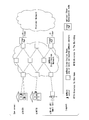
- FIG. 16 is a diagram showing the configuration of the millimeter wave distribution network cited from Non-Patent Document 1.
- Millimeter-wave distributed network is a usage model for constructing a relay network to replace optical fiber with millimeter waves.
- a millimeter wave distribution node (equivalent to a base station device installed in a base station) installed outdoors and a wireless device (mmWave Sector; installed in a terminal station) installed in a building Connected terminal device).
- mmWave Sector installed in a terminal station
- the millimeter-wave distributed network is characterized in that the millimeter-wave distributed node and the wireless device are fixedly installed.
- Patent Document 1 proposes an example of a station placement designing method that considers base station cooperative communication in a cellular mobile communication system.
- the station placement design support device shown in Patent Document 1 has, for example, the configuration shown in FIG. 1 of Patent Document 1.
- Patent Document 1 discloses the following procedure. That is, (1) the belonging base station, the cooperating base station, and the non-cooperating base station are determined for each section of the area based on the arrangement of the base stations in the area design target area and the radio wave propagation environment of each base station. To do. (2) The communication method of base station cooperative communication is determined based on the assumed radio wave state among the belonging base station, the cooperable base station, and the non-cooperative base station for each section of the area. (3) For each section of the area, the assumed wireless characteristic is calculated based on the communication method of base station cooperative communication.
- Patent Document 1 As described above, a means for grasping the radio wave propagation environment is required.
- Patent Document 2 proposes an example of a means for grasping the radio wave propagation environment required in the technique disclosed in Patent Document 1.
- patent document 2 as shown in the flowchart of FIG. 1 of patent document 2, the procedure of creating the data for determining the installation pattern of the base station of PHS(Personal Handy-phone System) is shown. The procedure is summarized as follows. That is, (1) a plurality of different installation patterns of PHS base stations are prepared for a predetermined service planning area, and the electric field intensity distribution is simulated for each installation pattern.
- the cost evaluation value is calculated based on the simulation result.
- the installation pattern for the service area plan is determined based on the quality evaluation value and the cost evaluation value.
- the movement of the terminal station and the diffraction of the radio waves are taken into consideration, so it is necessary to grasp the radio wave propagation environment in a wide area. Then, in order to grasp the radio wave propagation environment, it is necessary to carry out a simulation such as a ray trace method, but it is known that the calculation amount of the simulation is enormous.
- both the base station and the terminal station are installed at fixed positions, and the millimeter wave in which radio wave diffraction hardly occurs is used.
- a method different from the station design method applied to the mobile radio communication system can be applied. Therefore, a millimeter-wave radio communication system is desired to have a station design method that does not require a huge amount of calculation for grasping the radio wave propagation environment as in a mobile radio system.
- the present invention aims to provide a technique capable of reducing the amount of calculation in a millimeter wave wireless communication system.
- One aspect of the present invention is directed to a point cloud data acquisition step of acquiring point cloud data between a base station device and a terminal station device to form a point cloud data group, and the base station device and the terminal station device.
- a line-of-sight design method including a line-of-sight determination step of determining whether or not.
- One aspect of the present invention is the above-described station placement design method, wherein the non-line-of-sight region extraction step extracts the point-of-view data group when extracting the non-line-of-sight region at a position where the point-cloud data group is acquired. From the region specified by the radius corresponding to the acquired position, the remaining region excluding the region corresponding to the non-line-of-sight region already extracted at another position is scanned to detect the point cloud data, and the line-of-sight is detected. Extract the outer region.
- One aspect of the present invention is the above-mentioned station placement design method, which includes a base station installation candidate position acquisition step of obtaining information on a base station installation candidate position indicating a candidate for a position where the base station device is installed, For each base station installation candidate position, the point cloud data acquisition step, the Fresnel zone radius calculation step, the non-line-of-sight region extraction step, the area ratio calculation step, the received power estimation step, the The line-of-sight determination step is performed, and the base station installation candidate position that is determined to be line-of-sight is set as the base station installable position, and based on the information about the terminal station related to the base station installable position, the base station installable position A selection step of selecting a base station installation position from the inside.
- One aspect of the present invention is the above-described station placement design method, wherein when the line-of-sight determination step determines that there is line-of-sight, the base station device is based on the received power and a predetermined allowable maximum received power. Includes a received power comparison step of determining whether or not can be installed.
- One aspect of the present invention is the above-described station placement design method, wherein when the line-of-sight determination step determines that there is line-of-sight, the point cloud data of a position where the base station device is installed is acquired, and the acquired point is acquired.
- the method further includes a structural deterioration status determination step of determining whether or not the structure of the position where the base station device is installed is deteriorated based on the group data.
- One aspect of the present invention is directed to a point cloud data acquisition unit that acquires point cloud data between a base station device and a terminal station device to form a point cloud data group, and the base station device and the terminal station device.
- a Fresnel zone radius calculation unit that calculates a radius at each position where the point cloud data group is acquired in the first Fresnel zone, and a region that is specified by the radius for each position where the point cloud data group is acquired is scanned to
- a non-line-of-sight region extraction unit that detects point cloud data and extracts the non-line-of-sight region, the area of the region formed by the first Fresnel zone, and the ratio of the total area of all the extracted non-line-of-sight regions are calculated.
- An area ratio calculation unit a reception power estimation unit that estimates reception power based on the calculated ratio of the areas, and whether there is a line of sight between the base station device and the terminal station device based on the reception power. And a line-of-sight determining unit that determines whether or not the station-position designing device.
- One aspect of the present invention is the station placement design apparatus described above, wherein the non-line-of-sight region extraction unit extracts the point-cloud data group when extracting the non-line-of-sight region at a position where the point cloud data group is acquired. From the region specified by the radius corresponding to the acquired position, the remaining region excluding the region corresponding to the non-line-of-sight region already extracted at another position is scanned to detect the point cloud data, and the line-of-sight is detected. Extract the outer region.
- One aspect of the present invention is a station placement design program for causing a computer to execute each step of the station location design method described above.
- the present invention makes it possible to reduce the amount of calculation in a millimeter wave wireless communication system.
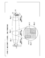
- FIG. 3 which shows the processing outline of the station placement design method in a 1st embodiment. It is a figure (the 4) which shows the processing outline of the station placement design method in a 1st embodiment. It is a figure (the 5) which shows the processing outline of the station design method in a 1st embodiment.
- FIG. 1 is a block diagram showing the configuration of the station placement design apparatus 1 according to the first embodiment.
- the station placement design is performed assuming the millimeter wave wireless communication system described above.
- the base station device 71 is fixedly installed on a pole such as a telephone pole or a pole
- the terminal station device 72 is fixedly installed on a building such as a house or a building. ..
- the locations where the base station device 71 and the terminal station device 72 are installed are the base station and the terminal station, respectively.
- one base station device 71 is installed in one base station. It is assumed that one terminal station device 72 is installed in one terminal station.
- the position of the terminal station device 72 is predetermined, and the installation position of the base station device 71 is arbitrarily selected by the user of the station placement designing device 1, for example.
- the station placement design apparatus 1 determines and presents whether or not the arbitrarily installed location of the base station apparatus 71 is appropriate for the location of the terminal station apparatus 72.
- the station placement design device 1 of the first embodiment uses the point cloud data to perform station placement design.
- the point cloud data is, for example, a high-density point cloud that can be acquired by using an in-vehicle laser measurement system MMS (Mobile Mapping System) in which a positioning sensor, a laser scanner, or the like is mounted on a vehicle. is there.
- MMS Mobile Mapping System
- Each of the points included in the point cloud has an xyz value.
- the station design device 1 includes a point cloud data acquisition unit 10, a Fresnel zone radius calculation unit 11, a non-line-of-sight region extraction unit 12, an area ratio calculation unit 13, a received power estimation unit 14, and a line-of-sight determination unit. 15 and a result output unit 16.
- the point cloud data acquisition unit 10 acquires the point cloud data of the target section from MMS or the like.
- the target section is, for example, a section between the base station apparatus 71 and the terminal station apparatus 72 shown in FIG.
- the point cloud data acquired by the point cloud data acquisition unit 10 is a group of point cloud data having a shape like a slice at a position where a shield exists in the target section (hereinafter referred to as “point cloud data group”). )It has become.
- the point cloud data acquisition unit 10 collects, for example, data collected in a certain range as a point cloud data group, and then detects the number of point cloud data groups.
- the point cloud data group is called a "group", but a group including one or more point cloud data is a point cloud data group.
- the number of point cloud data groups acquired by the point cloud data acquisition unit 10 is represented by “m”.
- the Fresnel zone radius calculation unit 11 uses the first Fresnel zone between the base station device 71 and the terminal station device 72 to determine the first Fresnel zone at each position where the point cloud data acquisition unit 10 has acquired the point cloud data group. Calculate the radius of the cross section. For example, as shown in FIG. 3, it is assumed that the base station device 71 is installed at the transmission point 31 and the terminal station device 72 is installed at the reception point 32. The positions of the base station device 71 and the terminal station device 72 may be reversed.
- the elliptic spherical first Fresnel zone 33 is defined for the transmission point 31 and the reception point 32.
- the first Fresnel zone 33 it is possible to define a circular cross section that intersects the straight line connecting the transmitting point 31 and the receiving point 32 at a right angle at an arbitrary position on the straight line connecting the transmitting point 31 and the receiving point 32.
- the Fresnel zone radius calculation unit 11 calculates the radius r of the cross section 30 of the first Fresnel zone 33 at the position P by the following equation (1).
- ⁇ is a wireless wavelength
- d 1 is a distance from the transmission point 31 to the position P
- d 2 is a distance from the position P to the reception point 32.
- the radius corresponding to the k-th point group data group is represented by radius r k .
- k is an integer of 1 to m.
- the non-line-of-sight area extraction unit 12 includes a scan processing unit 121 and a scan target exclusion area calculation unit 122.
- the scan processing unit 121 sets a region specified by the radius for each position where the point cloud data group calculated by the Fresnel zone radius calculation unit 11 is a scan target region. In addition, when the non-line-of-sight region is not extracted at another position, the scan processing unit 121 sets the entire scan target region as the scan region.
- the scan processing unit 121 excludes the excluded region calculated by the scan-target excluded region calculation unit 122 from the scan target region, and removes the excluded region.
- the scan area The scan processing unit 121 extracts a non-line-of-sight region by scanning and detecting a point group existing in the scan region. Further, the scan processing unit 121 outputs the information of all the non-line-of-sight regions extracted at each position to the area ratio calculation unit 13.
- the area 30-1 specified by the calculated radius r 1 becomes the scanning area.
- the scan target exclusion area calculation unit 122 enlarges or reduces all the non-line-of-sight areas already extracted by the scan processing unit 121 at other positions to a size corresponding to the radius r corresponding to the position of the next scan target. Then, the exclusion area is calculated. Further, the scan target exclusion area calculation unit 122 outputs the information on the calculated exclusion area to the scan processing unit 121.
- the non-line-of-sight region extraction unit 12 scans a region excluding the non-line-of-sight region detected by scanning the k-th point cloud data group from all k+1-th and subsequent scan target regions.
- the point cloud is scanned as an area.
- the non-line-of-sight region extraction unit 12 sets the newly detected non-line-of-sight region at the position immediately before and the region already excluded from the scan target region as the exclusion region, and the exclusion is performed.
- the region is excluded from the region to be scanned, and then the point cloud is scanned.
- the scan target exclusion area calculation unit 122 calculates the ratio between the radius r 1 and the radius r 2 . Since the radius r 2 is larger than the radius r 1 , the scan target exclusion area calculation unit 122 enlarges the size of the area 40-1 according to the calculated ratio to form the area 40-2.
- the scan target exclusion area calculation unit 122 outputs the area 40-2 as an exclusion area to the scan processing unit 121.
- the scan processing unit 121 scans the point cloud by using the area specified by the radius r 2 excluding the area 40-2 from the area 30-2 as a scan area, and the area 41-having a semi-cylindrical shape in which the point cloud exists. 2 is extracted as a non-line-of-sight region.
- the scan target exclusion area calculation unit 122 outputs the areas 40-3 and 41-3 to the scan processing unit 121 as exclusion areas.
- the scan processing unit 121 scans the point cloud with an area obtained by excluding the area 40-3 and the area 41-3 from the area 30-3 specified by the radius r 3 as a scanning area, and a rectangular shape in which the point cloud exists.
- Region 42-3 is extracted as a non-line-of-sight region.
- the area ratio calculation unit 13 calculates the area ratio between the area of the region constructed by the first Fresnel zone 33 and the total area of all the non-line-of-sight regions extracted by the non-line-of-sight region extraction unit 12.
- the area of the region constructed by the first Fresnel zone 33 is, for example, the area of the region specified by the radius r m of the first Fresnel zone 33 at the position of the m-th, that is, the last point cloud data group. ..
- the area ratio calculation unit 13 determines the area of the area 30-3 constructed by the first Fresnel zone 33 and the area that is not the line-of-sight area. The ratio with the total area of 40-3, 41-3, 42-3 is calculated.
- the reception power estimation unit 14 estimates the reception power from the area ratio calculated by the area ratio calculation unit 13.
- the line-of-sight determination unit 15 determines whether or not there is line-of-sight based on the received power estimated by the received power estimation unit 14.
- the result output unit 16 outputs information indicating whether the base station can be installed or not based on the determination result of the line-of-sight determination unit 15.
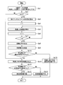
- FIG. 4 is a flowchart showing the flow of processing of the station placement designing method in the station placement designing apparatus 1.
- the position designing device 1 is provided with position information indicating the position of the base station device 71 and position information indicating the position of the terminal station device 72.
- the point cloud data acquisition unit 10 acquires the point cloud data of the target section from, for example, MMS (step Sa1, procedure 1 in FIG. 5).
- the point cloud data acquisition unit 10 collects the acquired point cloud data as several point cloud data groups.
- the point cloud data acquisition unit 10 detects the number "m” of point cloud data groups and determines whether the detected number "m” of point cloud data groups is not "0" (step Sa2).
- the result output unit 16 Upon receiving the determination result of the line-of-sight determination unit 15, the result output unit 16 outputs information indicating that the base station can be installed (step Sa11), and ends the process.
- step Sa2 Yes the point cloud data group is set to the Fresnel zone radius calculation unit 11, Output to the non-line-of-sight region extraction unit 12.
- the Fresnel zone radius calculation unit 11 calculates the radius r k of the first Fresnel zone 33 for each position of the point cloud data group based on the above equation (1).
- the Fresnel zone radius calculation unit 11 outputs all the calculated radii r k to the non-line-of-sight region extraction unit 12 (step Sa3, procedure 2 in FIG. 5).
- subscript "k" is the radius r k, merely subscript indicating the order, the radius r 1 shown in FIG. 5, the radius r 2, the length of the radius r 3, the radius r 1 shown in FIG. 2, respectively , Radius r 2 , and radius r 3 have different values.
- the scan processing unit 121 of the non-line-of-sight region extraction unit 12 substitutes “1” into the internal counter “i” (step Sa4).
- the non-line-of-sight region extraction unit 12 extracts the non-line-of-sight region by scanning the i-th point group data group in the i-th scanning region.
- the non-line-of-sight region extraction unit 12 sets the non-line-of-sight region detected by scanning the i-th point group data group as a scanning region by excluding the regions of all the scanning targets from the (i+1)th point onward.
- the point cloud is scanned in the scanning region (step Sa5).
- the scanning processing unit 121 substitutes a value obtained by adding “1” to the counter “i” into “i” (step Sa6).
- the scanning processing unit 121 determines whether i is larger than m (step Sa7).
- the scanning processing unit 121 determines that i is equal to or less than m
- the scanning processing unit 121 performs the process of step Sa5 again (step Sa7, No).
- the processing in the non-line-of-sight area extraction unit 12 is repeated for the number of point cloud data groups, that is, “m” times.
- the scanning processing unit 121 determines that i is larger than m, the scanning processing unit 121 outputs information on all the extracted non-line-of-sight regions to the area ratio calculation unit 13.
- step Sa5 will be specifically described with reference to FIGS. 6 to 8.
- the processing in step Sa5 differs depending on the value of "i”. If 6 "i" is "1", the scan processing unit 121 selects the circular region 30a-1 that is identified by a radius r 1 in the first Fresnel zone 33.
- the scan processing unit 121 does not use the circular area 30a-1 as a scanning area as it is, but scans a rectangular area determined based on the interval between the point clouds and the size of the area 30a-1. It is specified as 50-1.
- the scan processing unit 121 scans the point group in the scan area 50-1, and extracts the area 40a-1 including the four point groups as a non-line-of-sight area (procedure 3-1 in FIG. 6).
- the scan processing unit 121 instructs the scan target exclusion area calculation unit 122 to newly extract the i ⁇ 1th image.
- the exclusion area calculation request including the information of the outer area and the radius r i ⁇ 1 and the radius r i is output. Since the scan target exclusion area calculation unit 122 stores the information included in all the exclusion area calculation requests received from the scan processing unit 121 in the internal storage area, it includes the i-1th non-line-of-sight area and the non-line-of-sight area. It has radius information.
- the scan target exclusion area calculation unit 122 When the scan target exclusion area calculation unit 122 receives the exclusion area calculation request from the scan processing unit 121, the scan target exclusion area calculation unit 122 includes all the non-line-of-sight areas extracted by the scan processing unit 121 up to the i ⁇ 1th time in the exclusion area calculation request. The exclusion area is calculated by enlarging or reducing the size according to the existing radius r i . The scan target exclusion area calculation unit 122 outputs the calculated exclusion area information to the scan processing unit 121.
- the scan processing unit 121 informs the scan target exclusion region calculation unit 122 of the information of the region 40a-1 which is the first non-line-of-sight region, the radius r 1 and the radius.
- An exclusion area calculation request including r 2 is output.
- the scan target exclusion area calculation unit 122 calculates the ratio of the radius r 1 and the radius r 2 . Since the radius r 2 is twice the size of the radius r 1 , the scan target exclusion area calculation unit 122 enlarges the size of the area 40a-1 to 4 times and the area 40a including 16 point groups. -2 is calculated as an exclusion area.
- the scan target exclusion area calculation unit 122 outputs the area 40a-2 to the scan processing unit 121 as an exclusion area.
- the scan processing unit 121 receives the information of the region 40a-2 output by the scan target exclusion region calculation unit 122, and excludes the region 40a-2 from the next rectangular scan target region specified by the radius r 2 .
- the area is defined as a scanning area 50-2.
- the scan processing unit 121 scans the point group in the scan area 50-2 and extracts the area 41a-2 including the eight point groups as a non-line-of-sight area (procedure 3-2 in FIG. 7).
- An exclusion area calculation request including the radius r 2 and the radius r 3 is output.
- the scan target exclusion area calculation unit 122 calculates the ratio of the radius r 2 and the radius r 3 . Since the radius r 3 is 3/4 times as large as the radius r 2 , the scan target exclusion area calculation unit 122 reduces the size of the area 41a-2 to 9/16 times to make the area 41a-3 smaller. It is calculated as an exclusion area (procedure 3-3 in FIG. 8).
- the area 41a-2 is reduced to 9/16 times, the area 41a-2 can be reduced from 4 to 3 in the vertical direction, but from 2 to 1.5 in the horizontal direction. Since the decimal point appears, it is left as two without reduction.
- the scan target exclusion area calculation unit 122 reduces the size of the area 40a-2 to 9/16 times and calculates the area 40a-3 including nine point groups as an exclusion area.
- the scan target exclusion area calculation unit 122 outputs the calculated areas 40a-3 and 41a-3 to the scan processing unit 121 as exclusion areas.
- the scan processing unit 121 receives the information of the region 40a-3 and the region 41a-3 output by the scan target exclusion region calculation unit 122 and receives the region 40a from the region of the next rectangular scan target specified by the radius r 3 . -3 and the area excluding the area 41a-3 are set as the scanning area 50-3.
- the scan processing unit 121 scans the point group in the scan area 50-3 and extracts the area 43a-3 including the five point groups as a non-line-of-sight area.
- the area ratio calculation unit 13 calculates the area ratio between the area of the region constructed by the first Fresnel zone 33 and the total area of all the non-line-of-sight regions extracted by the non-line-of-sight region extraction unit 12 (step Sa8, FIG. Step 4 of 9). That is, the area ratio calculation unit 13 calculates the number of point clouds which are determined as the non-line-of-sight region at the position of the m-th point cloud data group output by the non-line-of-sight region extraction unit 12 as the total area of the non-line-of-sight regions. ..
- the area ratio calculation unit 13 calculates the area ratio by dividing the number of point groups that are regarded as non-line-of-sight regions by the total number of point groups.
- the number of point clouds that are not in the line-of-sight region at the position of the last third point cloud data group is 20, and the total number of point groups is 36.
- the area ratio calculated by the calculation unit 13 is “0.56”.
- the reception power estimation unit 14 performs a calculation for estimating the reception power from the area ratio calculated by the area ratio calculation unit 13 (step Sa9, procedure 5 in FIG. 9).
- the reception power estimation unit 14 calculates the reception power by combining a method of estimating the shielding loss from the ratio of the first Fresnel zone 33 and the shielding area with a propagation loss model.
- the line-of-sight determination unit 15 compares the received power estimated by the received power estimation unit 14 with a prescribed minimum received power that is a preset threshold value, and determines whether the received power is equal to or greater than the threshold value (step Sa10). , Step 6 in FIG. 9).
- the result output unit 16 outputs information indicating that the line-of-sight is available, that is, the base station can be installed (step S10). Sa11).
- the result output unit 16 outputs information indicating that there is no line-of-sight and base station installation is impossible (step S10). Sa12).
- the point cloud data acquisition unit 10 acquires point cloud data between the base station device 71 and the terminal station device 72 to form a point cloud data group.
- the Fresnel zone radius calculation unit 11 calculates the radius at each position where the point cloud data group of the first Fresnel zone 33 targeted for the base station device 71 and the terminal station device 72 is acquired.
- the non-line-of-sight region extraction unit 12 scans the region specified by the radius of each position where the point cloud data group is acquired, detects the point cloud data, and extracts the non-line-of-sight region.
- the area ratio calculation unit 13 calculates the ratio of the area of the region formed by the first Fresnel zone 33 and the total area of all the extracted non-line-of-sight regions.
- the reception power estimation unit 14 estimates the reception power based on the calculated area ratio.
- the line-of-sight determination unit 15 determines whether or not there is a line-of-sight between the base station device 71 and the terminal station device 72 based on the received power.
- the received power can be estimated using the point cloud data acquired in the target section such as between the base station device 71 and the terminal station device 72. Then, it is possible to easily grasp the radio wave propagation environment by determining the presence or absence of the line of sight based on the estimated received power. Therefore, the method according to the first embodiment is compared with, for example, an analysis method that performs a simulation such as a ray trace method for a wide area that has been implemented by a conventional station design that is applied to a mobile radio communication system or the like. It is possible to understand the radio wave propagation environment with a small amount of calculation. In other words, the station design apparatus 1 according to the first embodiment is applicable to a millimeter wave wireless communication system, and can easily grasp the radio wave propagation environment and reduce the amount of calculation.
- the calculation amount is further reduced by excluding the region corresponding to the non-line-of-sight region already extracted at another position from the region specified by the radius of the first Fresnel zone 33. ..
- the presence or absence of the line of sight can be determined based on the estimated received power while further reducing the calculation amount, and the installation position of the base station device 71 can be presented.
- the scan target exclusion area calculation unit 122 calculates the area 40-3 in FIG. 2, for example, based on the ratio of the radius r 2 and the radius r 3 to the area 40-. 2 is reduced to obtain the region 40-3. Also, when obtaining the region 40a-3 in FIG. 8, the region 40a-2 is reduced based on the ratio of the radius r 2 and the radius r 3.
- the configuration of the present invention is not limited to this embodiment. When determining the area 40-3, and the region 40a-3, based on the ratio of the radius r 1 and the radius r 3, region 40-1, and expand the region 40a-1, or reduced to regions 40-3 and, The area 40a-3 may be obtained.
- the area of the region formed by the first Fresnel zone 33 is the area of the region specified by the radius r m of the first Fresnel zone 33 at the position of the last point cloud data group.
- the area of the region constructed by the first Fresnel zone 33 is not limited to the position of the last point cloud data group, and may be the area of the region specified by the radius at the arbitrarily selected position.
- the area ratio calculation unit 13 needs to calculate the area of the region specified by the radius at the selected position.
- the area ratio calculation unit 13 enlarges or reduces all the non-line-of-sight regions at other positions according to the radius at the selected position, further adds the non-line-of-sight region at the selected position, and makes the selection. It is necessary to calculate the total area of the non-line-of-sight area at the position.
- the received power calculated by the received power estimation unit 14 in the example illustrated in FIG. 9 is in the non-line-of-sight area when the base station apparatus 71 is viewed from the terminal station apparatus 72 side.
- the calculated power is based on the received power of the terminal station device 72.
- the received power calculated by the received power estimation unit 14 is also the received power of the base station device 71.
- the non-line-of-sight region extraction unit 12 sets the non-line-of-sight region newly detected at the immediately preceding position and a region that has already been excluded from the scan target region as the exclusion region, The exclusion region is excluded from the region to be scanned, and then the point cloud is scanned.
- the non-line-of-sight region extraction unit 12 does not include the scan target exclusion region calculation unit 122, and the scan processing unit 121 scans the entire region specified by the radius of each position at all positions. Good.
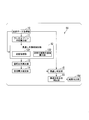
- FIG. 10 is a block diagram showing the configuration of the station placement design apparatus 1b according to the second embodiment.
- the same components as those in the first embodiment are designated by the same reference numerals, and different components will be described below.
- the millimeter wave wireless communication system is characterized in that both the base station device 71 and the terminal station device 72 are fixedly installed. Therefore, when the base station device 71 fails, the terminal station device 72 connected to the base station device 71 may be isolated. In order to prevent isolation, it is desirable to be able to prepare a base station device 71 that is an alternative connection destination.
- the station placement design device 1b includes a point cloud data acquisition unit 10, a Fresnel zone radius calculation unit 11, a non-line-of-sight region extraction unit 12, an area ratio calculation unit 13, a received power estimation unit 14, a line-of-sight determination unit 15b, and a result output unit 16b.
- the base station installation candidate position acquisition unit 17, the base station installable position acquisition unit 18, the connection information storage unit 19, the terminal station information acquisition unit 20, and the base station installation position selection unit 21 are provided.
- the base station installation candidate position acquisition unit 17 acquires a position that is a candidate for installing the base station device 71 (hereinafter, referred to as “base station installation candidate position”) by using, for example, map information.
- the base station installation candidate positions that are candidates for installing the base station device 71 are fixed positions such as utility poles and poles. Therefore, a plurality of positions are determined in advance in the map information, and the base station installation candidate position acquisition unit 17 selects and acquires at least one position as a base station installation candidate position from among them.
- the number of base station installation candidate positions acquired by the base station installation candidate position acquisition unit 17 is represented by “n”.
- n is an integer of 1 or more.
- the line-of-sight determination unit 15b determines whether or not the processing has been completed for all base station installation candidate positions. In addition, when the line-of-sight determination unit 15b determines that the processing has been completed for all base station installation candidate positions, it outputs the result of the line-of-sight determination for each base station installation candidate position to the base station installable position acquisition unit 18. To do.
- the base station installable position acquisition unit 18 installs a base station installation candidate position that has line-of-sight based on the result of the line-of-sight determination output by the line-of-sight determination unit 15b (hereinafter, “base station installable position”). That is)). Further, the base station installable position acquisition unit 18 detects the number of selected base station installable positions. In the following description, the number of base station installable positions detected by the base station installable position acquisition unit 18 is represented by “q”.
- the connection information storage unit 19 is, for example, a non-volatile storage area and stores in advance information about the terminal station. For example, as the information on the terminal station, the connection information storage unit 19 provides a perspective to the base station device 71 for each base station installation candidate position when the base station device 71 is installed at the position indicated by the base station installation candidate position. Information indicating the number of connectable terminal stations when the terminal station device 72 is installed, and information indicating each terminal station are stored in advance. In addition, the connection information storage unit 19 has the prospect of the terminal station device 72 installed in each of the terminal stations as the information about the terminal station, when the base station device 71 is installed. Information indicating the number of connectable base stations is stored in advance. The information about the terminal station stored in the connection information storage unit 19 may include the terminal station in which the terminal station device 72 that is the target of the line-of-sight determination is installed.
- the terminal station information acquisition unit 20 acquires information about the terminal station related to the base station installable position from the connection information storage unit 19 based on the base station installable position acquired by the base station installable position acquisition unit 18. ..
- the base station installation position selection unit 21 finally selects the position where the base station device 71 is installed based on the information about the terminal station device 72 acquired by the terminal station information acquisition unit 20.
- the result output unit 16b outputs information on the position where the base station device 71 selected by the base station installation position selection unit 21 is installed. Further, when the number “q” of the base station installable positions acquired by the base station installable position acquisition unit 18 is “0”, the result output unit 16b cannot install the base station at all base station installable candidate positions. The information indicating that is output.
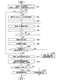
- the base station installation candidate position acquisition unit 17 selects n base station installation candidate positions from the map information, for example (step Sb1).
- the base station installation candidate position acquisition unit 17 substitutes “1” into the internal counter “j”, and the base station installation candidate position acquisition unit 17 selects any one of the acquired base station installation candidate positions.
- the installation candidate position is selected and output to the point cloud data acquisition unit 10 (step Sb2).
- the point cloud data acquisition unit 10 Upon receiving the base station installation candidate position from the base station installation candidate position acquisition unit 17, the point cloud data acquisition unit 10 sets the base station installation candidate position as the position where the base station device 71 is installed.
- the point cloud data acquisition unit 10, Fresnel zone radius calculation unit 11, non-line-of-sight region extraction unit 12, area ratio calculation unit 13, received power estimation unit 14, and line-of-sight determination unit 15b are the first embodiment shown in FIG.
- the processing from step Sa1 to step Sa12 is started as a subroutine (step Sb3).
- step Sb3 of the second embodiment in step Sa11 and step Sa12, the result output unit 16b does not output the information, and the line-of-sight determination unit 15b sets the determination result to the base station installation candidate position. It is replaced with a process of associating and storing in an internal storage area. Further, the last process in FIG. 4 is not a termination process but a “Return” process that exits the subroutine.
- the line-of-sight determination unit 15b indicates that the line-of-sight determination is completed when the line-of-sight determination between the terminal station device 72 and the base station installation candidate position given by the base station installation candidate position acquisition unit 17 to the point cloud data acquisition unit 10 is completed.
- the information is output to the base station installation candidate position acquisition unit 17.
- the base station installation candidate position acquisition unit 17 receives the information indicating the end and substitutes the value obtained by adding "1" to the internal counter "j" to "j" (step Sb4).
- the base station installation candidate position acquisition unit 17 determines whether j is larger than n (step Sb5). When the base station installation candidate position acquisition unit 17 determines that j is n or less (step Sb5, No), the process is returned to step Sb3. That is, the base station installation candidate position acquisition unit 17 selects any one base station installation candidate position from the unprocessed base station installation candidate positions among the acquired base station installation candidate positions to acquire the point cloud data. Output to the unit 10. As a result, the process of step Sb3 is repeated for the number of base station installation candidate positions, that is, “n” times.
- the base station installation candidate position acquisition unit 17 determines that j is larger than n (Yes in step Sb5), the base station installation candidate position acquisition unit 17 outputs information indicating a determination result output instruction to the visibility determination unit 15b.
- the line-of-sight determination unit 15b Upon receiving the information indicating the output instruction from the base station installation candidate position acquisition unit 17, the line-of-sight determination unit 15b sends the determination result for each base station installation candidate position stored in the internal storage area to the base station installable position acquisition unit 18. Output.
- the base station installable position acquisition unit 18 acquires, as base station installable positions, all base station installation candidate positions that have been determined to have line-of-sight, based on the result of the line-of-sight determination output by the line-of-sight determination unit 15b. , The number “q” of base station installable positions is detected (step Sb6). The base station installable position acquisition unit 18 determines whether the value of “q” is not “0” (step Sb7).
- the result output unit 16b receives the estimated reception at all base station installation candidate positions.
- the power is less than the specified minimum received power, the information indicating that there is no line of sight, that is, the base station cannot be installed is output (step Sb11), and the process ends.
- step Sb7 when the base station installable position acquisition unit 18 determines that the value of “q” is not “0” (step Sb7, Yes), all the acquired base station installable position information is acquired by the terminal station information acquisition unit. Output to 20.
- the terminal station information acquisition unit 20 acquires information about the terminal station related to the base station installable position from the connection information storage unit 19 based on the base station installable position received from the base station installable position acquisition unit 18. ..
- the terminal station information acquisition unit 20 outputs the acquired information about the terminal station to the base station installation position selection unit 21 (step Sb8).
- the base station installation position selection unit 21 finally selects the base station installation position where the base station device 71 is installed based on the information about the terminal station received from the terminal station information acquisition unit 20 (step Sb9).
- the conditions for how the base station installation position selection unit 21 selects the final base station installation position can be set arbitrarily. For example, it is assumed that the terminal station device 72 that is the subject of line-of-sight determination is in a state where it cannot connect to the base station device 71 in the information stored in the connection information storage unit 19. In this case, if the base station installation position selecting unit 21 selects the positions of at least two base station installations 71 to which the terminal station device 72 of the line-of-sight determination target can be connected, the base station device 71 as the alternative connection destination. Can be secured.
- the terminal station device 72 that is the subject of line-of-sight determination is already in a state capable of being connected to one base station device 71 in the information stored in the connection information storage unit 19.
- the base station installation position selection unit 21 selects one base station installation position to which the terminal station device 72 that is the subject of the line-of-sight determination can connect, the base station device 71 that is the alternative connection destination can be secured. It will be possible.
- the base station installation position selection unit 21 determines, for example, a position that can be connected to the terminal station device 72 having the smallest number of connectable base stations as the base station installation position. You may choose.
- the base station installation position selection unit 21 may select, for example, a position that can be connected to the most terminal station devices 72 as the base station installation position. By selecting in this way, when the processing shown in FIG. 11 is performed with respect to the other terminal station device 72, there is a line of sight with many base station devices 71 in advance, that is, a connectable state is set. Can be set.
- the base station installation position selection unit 21 outputs information on the selected base station installation position to the result output unit 16b.
- the result output unit 16b outputs the information of the base station installation position received from the base station installation position selection unit 21 together with the information indicating that there is line-of-sight, that is, the base station installation is possible (step Sb10).
- the station placement design device 1b performs the line-of-sight determination in the configuration of the first embodiment for a plurality of base station installation candidate positions, and the base station installation candidate determined to have line-of-sight.
- the position is set as the base station installable position, and the base station installable position is selected from the base station installable positions based on the information about the terminal station related to the base station installable position. Therefore, it is possible to design the station placement considering the line-of-sight, that is, the number of base station devices 71 that can secure the connection.
- the terminal station device 72 is also fixedly installed.
- the base station device 71 fails, the base station device 71 as an alternative connection destination is required so that the terminal station device 72 is not isolated. Is.
- the station placement design apparatus 1b of the second embodiment the station location design is performed so that the terminal station apparatus 72 can be connected to a plurality of base station apparatuses 71. There is. Therefore, in the second embodiment, in addition to the effect obtained by the configuration of the first embodiment, continuity of communication can be enhanced when a failure occurs in the base station device 71, and fault tolerance is high. It is possible to design station placement.
- connection information storage unit 19 is configured to store information about the terminal station device 72 in advance, but the configuration of the present invention is not limited to this embodiment. ..
- the information indicating the relationship between the base station installation position and the terminal station which is obtained by repeatedly performing the processing of FIG. 11 for a plurality of terminal station devices 72, is accumulated in the connection information storage unit 19, and the accumulated information is stored. May be used in the process of step Sb9.
- FIG. 12 is a block diagram showing the configuration of the station design apparatus 1c in the third embodiment.
- the same configurations as those in the first embodiment are designated by the same reference numerals, and different configurations will be described below.
- the millimeter wave wireless communication system is characterized in that both the base station device 71 and the terminal station device 72 are fixedly installed. When fixedly installed, the amount of received electric power of the radio wave received by the base station device 71 or the terminal station device 72 may be fixed. In that case, if the base station device 71 or the terminal station device 72 receives an excessive input for receiving a radio wave of excessive power, the operation of the device may become unstable and communication may not be possible. In order to prevent an excessive input, it is desirable to set some restrictions on the received power.
- the station design device 1c includes a point cloud data acquisition unit 10, a Fresnel zone radius calculation unit 11, a non-line-of-sight region extraction unit 12, an area ratio calculation unit 13, a received power estimation unit 14, a line-of-sight determination unit 15, and a result output unit 16c. And a received power comparison unit 22.
- the reception power comparison unit 22 compares the reception power estimated by the reception power estimation unit 14 with the maximum allowable reception power that is a predetermined threshold value, and thus an excessive input is detected. Judge whether there is a possibility of occurrence.
- the result output unit 16c outputs information indicating whether the base station can be installed or not, based on the comparison result of the reception power comparison unit 22.
- step Sc1 to step Sc10 shown in FIG. 13 is the same as the processing from step Sa1 to step Sa10 of the station placement designing method of the first embodiment shown in FIG.
- the reception power estimation unit 14 performs a process of outputting the calculated reception power to the reception power comparison unit 22 in addition to the process of step Sa9.
- the result output unit 16c performs the same process as the process performed by the result output unit 16 in step Sa12 of FIG.
- the processing from step Sc11 to step Sc14 which is different from the first embodiment, will be described.
- step Sc10 when the line-of-sight determination unit 15 determines that the received power is equal to or higher than the minimum received power (Yes in step Sc10), the line-of-sight determination unit 15 outputs the determination result of the line-of-sight to the received power comparison unit 22.
- the reception power comparison unit 22 compares the reception power received from the reception power estimation unit 14 when receiving the determination result of the line-of-sight with a predetermined allowable maximum power, and the reception power is equal to or less than the allowable maximum power. It is determined whether or not (step Sc12).
- the result output unit 16c determines that there is no risk of an excessive input, and the base station can be installed in the result output unit 16c. Information indicating that there is is output (step Sc13).
- the received power comparison unit 22 determines that the received power exceeds the maximum allowable power (No in Step Sc12)
- the result output unit 16c determines that the base station cannot be installed because the excessive input may occur.
- the information indicating that is output (step Sc14).
- the station design device 1c determines that there is a line-of-sight, whether or not the base station device 71 can be installed based on the received power and the predetermined maximum allowable received power. Determine whether. Therefore, it is possible to design the station placement with the constraint that the received power is equal to or less than the maximum allowable received power.
- the terminal station device 72 since the terminal station device 72 is also fixedly installed, if the base station device 71 or the terminal station device 72 receives a radio wave of excessive power, the operation of the device becomes unstable and communication cannot be performed. It may disappear.
- the station placement designing apparatus 1c of the third embodiment in addition to the effect obtained by the configuration of the first embodiment, the base station apparatus 71 or the terminal station apparatus 72 is overloaded. It becomes possible to prevent input.
- a separation distance comparison unit that compares the distance between the base station device 71 and the terminal station device 72 with a predetermined minimum separation distance. May be.
- the separation distance comparison unit determines that the distance between the base station device 71 and the terminal station device 72 in the process of step Sc12 is a distance at which the excessive input is not generated if the distance is, for example, the minimum separation distance or more. It is determined that there is (step Sc12, Yes).
- the separation distance comparison unit determines that the distance between the base station device 71 and the terminal station device 72 is a distance at which an excessive input may occur if the distance is less than the minimum separation distance (step Sc12). , No).
- FIG. 14 is a block diagram showing the configuration of the station placement design apparatus 1d according to the fourth embodiment.
- the same configurations as those in the first embodiment are designated by the same reference numerals, and different configurations will be described below.
- the millimeter wave wireless communication system is characterized in that both the base station device 71 and the terminal station device 72 are fixedly installed. Therefore, it is necessary to install the base station device 71 on a telephone pole, pole, or the like in which structural deterioration has not occurred.
- the station design device 1d includes a point cloud data acquisition unit 10, a Fresnel zone radius calculation unit 11, a non-line-of-sight region extraction unit 12, an area ratio calculation unit 13, a received power estimation unit 14, a line-of-sight determination unit 15, and a result output unit 16d. And a structural deterioration status determination unit 23.
- the structural deterioration status determination unit 23 acquires point cloud data of the base station installation candidate position that is determined to have a line-of-sight from, for example, MMS, and analyzes and analyzes the data. The presence or absence of structural deterioration is determined from the result.
- the analysis result is information such as the inclination and deflection of the electric pole and pole obtained by analyzing from the point cloud data acquired by the structural deterioration state determination unit 23.
- the structural deterioration status determination unit 23 determines the structural deterioration based on the information such as the inclination and the deflection obtained by the analysis and a predetermined threshold value.
- the result output unit 16d outputs information indicating whether the base station can be installed or not based on the determination result of the structural deterioration in the structural deterioration state determination unit 23.
- step Sd1 to step Sd10 shown in FIG. 15 is the same as the processing from step Sa1 to step Sa10 of the station placement designing method of the first embodiment shown in FIG.
- the result output unit 16d in step Sd16 of FIG. 15 performs the same process as the process performed by the result output unit 16 in step Sa12 of FIG.
- steps Sd11 to Sd15 which are different from those of the first embodiment, will be described below.
- step Sd10 when the line-of-sight determination unit 15 determines that the received power is equal to or higher than the minimum received power (Yes in step Sd10), the line-of-sight determination unit 15 outputs the determination result of the line-of-sight to the structural deterioration state determination unit 23. Yes (step Sd11).
- the structural deterioration state determination unit 23 Upon receiving the determination result that the line-of-sight is present, the structural deterioration state determination unit 23 acquires point cloud data of the base station installation candidate position determined to be line-of-sight from the MMS or the like and analyzes it (step Sd12).
- the structural deterioration status determination unit 23 determines whether or not there is structural deterioration based on information such as the inclination and deflection of the electric poles and poles and the threshold value that is predetermined corresponding to each information (step Sd13). ).
- the result output unit 16c outputs information indicating that the base station can be installed (step Sd14).
- the result output unit 16c outputs information indicating that the base station installation is impossible (step Sd15).
- the station design device 1d determines that there is a line-of-sight, it acquires the point cloud data of the candidate position where the base station device 71 is installed, and based on the acquired point cloud data. It is determined whether or not the structure of the candidate position where the base station device 71 is installed is deteriorated. Therefore, it is possible to indicate whether the base station can be installed or not based on the structural deterioration situation of the base station installation candidate position. Therefore, by applying the station placement design apparatus 1d of the fourth embodiment, in addition to the effect obtained by the configuration of the first embodiment, the base station apparatus 71 can be installed at a position where the structure is more robust. It will be possible.
- the configurations of the second to fourth embodiments described above may be combined and used.
- the method of selecting the installation position of the base station device 71 of the first to fourth embodiments reverses the relationship between the base station device 71 and the terminal station device 72, and selects the installation position of the terminal station device 72. It may be applied to the method.
- the determination process using the inequality sign is performed in the processes shown in step Sa10 of FIG. 4, steps Sc10 and Sc12 of FIG. 13, and steps Sd10 and Sd13 of FIG.
- the present invention is not limited to the embodiment, and the determination process of “whether or not it is greater than or equal to” and “whether or not less than” is merely an example, and for example, in determining a threshold value. Accordingly, it may be replaced with the determination process of “whether or not to exceed” and “whether or not to be less”, respectively.
- the threshold used in the determination process is also an example, and different thresholds may be applied to each.
- the station placement designing devices 1, 1b, 1c, 1d in the above-described first to fourth embodiments can also be realized by a computer and a program, and the program can be recorded in a recording medium or provided through a network. is there. That is, a program for realizing this function may be recorded in a computer-readable recording medium, and the program recorded in this recording medium may be read by a computer system and executed.
- the “computer system” mentioned here includes an OS and hardware such as peripheral devices.
- the “computer-readable recording medium” refers to a portable medium such as a flexible disk, a magneto-optical disk, a ROM, a CD-ROM, or a storage device such as a hard disk built in a computer system.
- the "computer-readable recording medium” means to hold a program dynamically for a short time like a communication line when transmitting the program through a network such as the Internet or a communication line such as a telephone line.
- a volatile memory inside a computer system that serves as a server or a client in that case, which holds a program for a certain period of time may be included.
- the program may be for realizing a part of the functions described above, or may be a program that can realize the functions described above in combination with a program already recorded in a computer system, It may be realized using a programmable logic device such as FPGA (Field Programmable Gate Array).
- SYMBOLS 1 Station design apparatus, 10... Point cloud data acquisition unit, 11... Fresnel zone radius calculation unit, 12... Non-line-of-sight region extraction unit, 13... Area ratio calculation unit, 14... Received power estimation unit, 15... Line-of-sight determination unit , 16... Result output section
Landscapes
- Engineering & Computer Science (AREA)
- Computer Networks & Wireless Communication (AREA)
- Signal Processing (AREA)
- Physics & Mathematics (AREA)
- Electromagnetism (AREA)
- Mobile Radio Communication Systems (AREA)
- Quality & Reliability (AREA)
Abstract
基地局装置と端末局装置の間の点群データを取得して点群データ群とし、前記基地局装置と前記端末局装置を対象とした第1フレネルゾーンの前記点群データ群を取得した各位置における半径を算出し、前記点群データ群を取得した位置ごとの前記半径によって特定される領域を走査して前記点群データを検出して見通し外領域を抽出し、第1フレネルゾーンが構築する領域の面積と、抽出した全ての前記見通し外領域を総和した面積との比率を算出し、算出した前記面積の比率に基づいて受信電力を推定し、前記受信電力に基づいて、前記基地局装置と前記端末局装置の間に見通しがあるか否かを判定する。
Description
本発明は、置局設計方法、置局設計装置、及び置局設計プログラムに関する。
現在、次世代60GHz帯無線LAN(Local Area Network)規格として、IEEE802.11ayの議論が行われている。非特許文献1に記載されているように、IEEE802.11ayでは様々なユーセージモデルが検討されており、2017年7月に追加されたモデルに「ミリ波分散ネットワーク」(mmWave Distribution Network)がある。
図16は、非特許文献1から引用したミリ波分散ネットワークの構成を示す図である。
ミリ波分散ネットワークは光ファイバを代替する中継網をミリ波で構築するためのユーセージモデルである。ミリ波分散ネットワークでは、屋外に設置されたミリ波分散ノード(mmWave Distribution Node;基地局に設置される基地局装置に相当)と、建物内に設置された無線機(mmWave Sector;端末局に設置される端末局装置)とが接続する。また、ミリ波分散ネットワークでは、ミリ波分散ノードと無線機が、固定設置されることが特徴である。
ミリ波分散ネットワークは光ファイバを代替する中継網をミリ波で構築するためのユーセージモデルである。ミリ波分散ネットワークでは、屋外に設置されたミリ波分散ノード(mmWave Distribution Node;基地局に設置される基地局装置に相当)と、建物内に設置された無線機(mmWave Sector;端末局に設置される端末局装置)とが接続する。また、ミリ波分散ネットワークでは、ミリ波分散ノードと無線機が、固定設置されることが特徴である。
無線通信システムを運用するためには、ユーザに十分な無線通信の環境を提供する必要があり、それには、基地局、または端末局を適切な位置に設置する置局設計が求められる。携帯電話に代表される移動無線通信システムでは、端末局が移動することや電波が回折する極超短波を使用することなどを考慮した置局設計が必要とされる。
例えば、特許文献1には、セルラ移動通信システムにおいて、基地局連携通信を考慮する置局設計方法の一例が提案されている。特許文献1に示される置局設計支援装置は、例えば、特許文献1の図1に示される構成を備えている。また、特許文献1には、以下のような手順が示されている。すなわち、(1)置局設計対象エリア内の基地局の配置および各基地局の電波伝搬環境に基づいて当該エリアの区画ごとに所属基地局、連携可能基地局、および、非連携基地局を決定する。(2)当該エリアの区画ごとに所属基地局、連携可能基地局、および、非連携基地局の間の想定電波状態に基づいて基地局連携通信の通信方法を決定する。(3)当該エリアの区画ごとに、基地局連携通信の通信方法に基づいて想定無線特性を算出する。
特許文献1では、上述したように、電波伝搬環境を把握する手段が必要となる。特許文献2では、特許文献1に示される技術において必要となる電波伝搬環境を把握する手段の一例が提案されている。特許文献2では、特許文献2の図1のフローチャートに示すように、PHS(Personal Handy-phone System)の基地局の設置パターンを決定するためのデータの作成を行う手順が示されている。この手順を要約すると、以下のような手順となる。すなわち、(1)所定のサービス計画エリアに対して、PHS基地局の複数の異なる設置パターンを用意し、各設置パターンについて、電界強度分布のシミュレーションを行う。(2)各設置パターンに対して、シミュレーション結果に基づいて、サービスエリア計画エリアの面積に対する通話可能エリアの面積の比率を品質評価値として算出することに加え、コスト評価値を算出する。(3)品質評価値とコスト評価値に基づいて、サービスエリア計画に対する設置パターンを決定する。
「IEEE802.11 TGay Use Cases」、IEEE 802.11-2015/0625r7、2017年8月
上述したように、移動無線通信システムに対する置局設計方法では、端末局の移動や電波の回折を考慮することになるため、幅広いエリアの電波伝搬環境を把握することが必要となる。そして、電波伝搬環境を把握するためには、レイトレース法などのシミュレーションを実施することが必要となるが、当該シミュレーションの計算量は膨大であることが知られている。
これに対して、上述したミリ波分散ネットワークに代表されるミリ波無線通信システムでは、基地局と端末局の両方が固定した位置に設置されることや電波の回折がほぼ発生しないミリ波を使用するといった特徴がある。したがって、ミリ波無線通信システムの場合、移動無線通信システムに適用されている置局設計方法とは異なる方法を適用することができる。そのため、移動無線システムのように電波伝搬環境の把握に要する計算量が膨大にならないような置局設計方法がミリ波無線通信システムでは望まれている。
上記事情に鑑み、本発明は、ミリ波無線通信システムにおいて計算量を削減することができる技術の提供を目的としている。
本発明の一態様は、基地局装置と端末局装置の間の点群データを取得して点群データ群とする点群データ取得ステップと、前記基地局装置と前記端末局装置を対象とした第1フレネルゾーンの前記点群データ群を取得した各位置における半径を算出するフレネルゾーン半径算出ステップと、前記点群データ群を取得した位置ごとの前記半径によって特定される領域を走査して前記点群データを検出して見通し外領域を抽出する見通し外領域抽出ステップと、第1フレネルゾーンが構築する領域の面積と、抽出した全ての前記見通し外領域を総和した面積との比率を算出する面積比率算出ステップと、算出した前記面積の比率に基づいて受信電力を推定する受信電力推定ステップと、前記受信電力に基づいて、前記基地局装置と前記端末局装置の間に見通しがあるか否かを判定する見通し判定ステップと、を含む置局設計方法である。
本発明の一態様は、上記の置局設計方法であって、前記見通し外領域抽出ステップは、前記点群データ群を取得した位置において前記見通し外領域を抽出する際、当該点群データ群を取得した位置に対応する前記半径によって特定される領域から、他の位置において既に抽出した前記見通し外領域に相当する領域を除外した残りの領域を走査して前記点群データを検出し、前記見通し外領域を抽出する。
本発明の一態様は、上記の置局設計方法であって、前記基地局装置を設置する位置の候補を示す基地局設置候補位置の情報を取得する基地局設置候補位置取得ステップを含み、前記基地局設置候補位置の各々に対して、前記点群データ取得ステップと、前記フレネルゾーン半径算出ステップと、前記見通し外領域抽出ステップと、前記面積比率算出ステップと、前記受信電力推定ステップと、前記見通し判定ステップとを行い、見通しありと判定された基地局設置候補位置を基地局設置可能位置とし、前記基地局設置可能位置に関連する端末局に関する情報に基づいて、前記基地局設置可能位置の中から基地局設置位置を選択する選択ステップと、を含む。
本発明の一態様は、上記の置局設計方法であって、前記見通し判定ステップが見通しありと判定した場合、前記受信電力と、予め定められる許容最大受信電力とに基づいて、前記基地局装置が設置可能か否かを判定する受信電力比較ステップを含む。
本発明の一態様は、上記の置局設計方法であって、前記見通し判定ステップが見通しありと判定した場合、前記基地局装置を設置する位置の前記点群データを取得し、取得した前記点群データに基づいて、前記基地局装置を設置する位置の構造が劣化しているか否かを判定する構造劣化状況判定ステップをさらに含む。
本発明の一態様は、基地局装置と端末局装置の間の点群データを取得して点群データ群とする点群データ取得部と、前記基地局装置と前記端末局装置を対象とした第1フレネルゾーンの前記点群データ群を取得した各位置における半径を算出するフレネルゾーン半径算出部と、前記点群データ群を取得した位置ごとの前記半径によって特定される領域を走査して前記点群データを検出して見通し外領域を抽出する見通し外領域抽出部と、第1フレネルゾーンが構築する領域の面積と、抽出した全ての前記見通し外領域を総和した面積との比率を算出する面積比率算出部と、算出した前記面積の比率に基づいて受信電力を推定する受信電力推定部と、前記受信電力に基づいて、前記基地局装置と前記端末局装置の間に見通しがあるか否かを判定する見通し判定部と、を備える置局設計装置である。
本発明の一態様は、上記の置局設計装置であって、前記見通し外領域抽出部は、前記点群データ群を取得した位置において前記見通し外領域を抽出する際、当該点群データ群を取得した位置に対応する前記半径によって特定される領域から、他の位置において既に抽出した前記見通し外領域に相当する領域を除外した残りの領域を走査して前記点群データを検出し、前記見通し外領域を抽出する。
本発明の一態様は、コンピュータに、上記に記載の置局設計方法の各過程を実行させるための置局設計プログラムである。
本発明により、ミリ波無線通信システムにおいて計算量を削減することが可能になる。
(第1の実施形態)
以下、本発明の実施形態について図面を参照して説明する。
図1は、第1の実施形態における置局設計装置1の構成を示すブロック図である。第1の実施形態の置局設計装置1では、上述したミリ波無線通信システムを想定した置局設計を行う。
以下、本発明の実施形態について図面を参照して説明する。
図1は、第1の実施形態における置局設計装置1の構成を示すブロック図である。第1の実施形態の置局設計装置1では、上述したミリ波無線通信システムを想定した置局設計を行う。
図2に示すように、ミリ波無線通信システムでは、例えば、基地局装置71は、電柱やポールなどの柱に固定設置され、端末局装置72は、家屋やビルなどの建物に固定設置される。なお、基地局装置71と端末局装置72が設置される場所が、それぞれ基地局と端末局となり、以下の各実施形態では、1つの基地局には、1台の基地局装置71が設置され、1つの端末局には、1台の端末局装置72が設置されるものとする。
また、第1の実施形態では、端末局装置72の位置は予め定められており、基地局装置71の設置位置については、例えば、置局設計装置1の利用者が任意に選択する。置局設計装置1は、任意に選択された基地局装置71の設置位置が、端末局装置72の位置に対して適切であるか否かを判定して提示する。
第1の実施形態の置局設計装置1は、点群データを利用して置局設計を行う。ここで、点群データとは、例えば、測位センサやレーザスキャナなどを車両に搭載した車載型レーザ計測システムであるMMS(Mobile Mapping System)などを利用して取得できる高密度な点群のことである。点群に含まれる点の各々は、xyz値を有する。点群データを解析することで物体の位置や形状の把握を行うことが可能となる。例えば、下記の参考文献では、MMSを利用して取得した点群データから道路エッジ、ポール、標識を抽出する技術を紹介している。
「参考文献:所 克巌、真鍋鎮男、北川育夫、佐藤俊明、「MMSによる3次元点群データからの道路縁・ポール・標識の抽出」、2016年度精密工学会春季大会学術講演会講演論文集、精密工学会、2016年3月、777-778頁」
図1に示すように、置局設計装置1は、点群データ取得部10、フレネルゾーン半径算出部11、見通し外領域抽出部12、面積比率算出部13、受信電力推定部14、見通し判定部15、及び結果出力部16を備える。
点群データ取得部10は、MMSなどから対象区間の点群データを取得する。ここで、対象区間とは、例えば、図2に示す基地局装置71と端末局装置72との間の区間である。点群データ取得部10が取得する点群データは、対象区間において遮蔽物が存在する位置に対してスライスを切ったような形状の点群データの群(以下、「点群データ群」という。)になっている。点群データ取得部10は、取得した点群データのうち、例えば、一定の範囲にまとまっているものを点群データ群としてまとめた上で、点群データ群の数を検出する。なお、点群データ群は、「群」と呼んでいるが、1つ以上の点群データを含むものを点群データ群とする。また、以下の説明において、点群データ取得部10が取得した点群データ群の数を「m」で表す。
フレネルゾーン半径算出部11は、基地局装置71と端末局装置72の間の第1フレネルゾーンに基づいて、点群データ取得部10が点群データ群を取得した位置の各々における第1フレネルゾーンの断面の半径を算出する。例えば、図3に示すように、基地局装置71が、送信点31に設置され、端末局装置72が、受信点32に設置されるとする。なお、基地局装置71と端末局装置72の位置は逆であってもよい。
このとき、送信点31と受信点32とに対して、楕円球形状の第1フレネルゾーン33が定められる。第1フレネルゾーン33において、送信点31と受信点32を結ぶ直線上の任意の位置において送信点31と受信点32を結ぶ直線と直角に交わる円形の断面を定めることができる。
点群データ取得部10が出力する点群データ群が、位置Pにおける断面30を含む平面上において取得された点群データ群であるとする。この場合、フレネルゾーン半径算出部11は、位置Pにおける第1フレネルゾーン33の断面30の半径rを次式(1)によって算出する。

なお、式(1)においてλは、無線の波長であり、d1は、送信点31から位置Pまでの距離であり、d2は、位置Pから受信点32までの距離である。なお、以下の説明において、k番目の点群データ群に対応する半径を半径rkで表すとする。ここで、kは1~mの整数である。
見通し外領域抽出部12は、走査処理部121と走査対象除外領域算出部122を備える。走査処理部121は、フレネルゾーン半径算出部11が算出した点群データ群が存在する位置ごとの半径によって特定される領域を走査対象の領域とする。また、走査処理部121は、他の位置において見通し外領域を抽出していない場合、走査対象の領域の全てを走査領域とする。
また、走査処理部121は、既に他の位置において見通し外領域を抽出している場合、走査対象除外領域算出部122が算出する除外領域を走査対象の領域から除外し、除外した後の領域を走査領域とする。走査処理部121は、走査領域に存在する点群を走査して検出することにより見通し外領域を抽出する。また、走査処理部121は、各々の位置において抽出した全ての見通し外領域の情報を面積比率算出部13に出力する。
図2に示す例では、点群データ取得部10は、m=3、すなわち3つの点群データ群を取得している。フレネルゾーン半径算出部11は、例えば、m=1の点群データ群の第1フレネルゾーン33の半径を半径r1として算出する。算出した半径r1によって特定される領域30-1が走査領域となる。走査処理部121は、当該走査領域において点群を走査して、点群が存在する扇形形状の領域40-1をm=1における見通し外領域として抽出する。
走査対象除外領域算出部122は、走査処理部121が他の位置において既に抽出した全ての見通し外領域を、次の走査対象の位置に対応する半径rに応じた大きさに拡大、または縮小して除外領域を算出する。また、走査対象除外領域算出部122は、算出した除外領域の情報を走査処理部121に出力する。
別の言い方をすれば、見通し外領域抽出部12は、k番目の点群データ群を走査することにより検出した見通し外領域を、k+1番目以降の全ての走査対象の領域から除いた領域を走査領域として点群の走査を行っている。また、さらに別の言い方をすれば、見通し外領域抽出部12は、1つ前の位置において新たに検出した見通し外領域と、既に走査対象の領域から除外した領域とを除外領域とし、当該除外領域を走査対象の領域から除外した上で、点群の走査を行っている。
例えば、図2に示す例において、フレネルゾーン半径算出部11が算出するm=2の場合の第1フレネルゾーン33の半径が半径r2であるとする。走査対象除外領域算出部122は、半径r1と、半径r2との比率を算出する。半径r1よりも半径r2の方が大きいため、走査対象除外領域算出部122は、領域40-1の大きさを算出した比率に応じて拡大して領域40-2とする。走査対象除外領域算出部122は、領域40-2を除外領域として走査処理部121に出力する。
走査処理部121は、半径r2によって特定される領域30-2から領域40-2を除外した領域を走査領域として、点群を走査して、点群が存在する蒲鉾形形状の領域41-2を見通し外領域として抽出する。走査処理部121は、抽出した領域41-2と、除外した領域40-2とをまとめてm=2における見通し外領域とする。
同様に、フレネルゾーン半径算出部11が算出するm=3の場合の第1フレネルゾーン33の半径が半径r3であるとする。走査対象除外領域算出部122は、半径r2と、半径r3の比率を算出する。半径r2よりも半径r3が小さいため、走査対象除外領域算出部122は、m=2における見通し外領域、すなわち、領域40-2と領域41-2の大きさを算出した比率に応じて縮小してそれぞれ領域40-3と領域41-3とする。走査対象除外領域算出部122は、領域40-3と領域41-3を除外領域として走査処理部121に出力する。
走査処理部121は、半径r3によって特定される領域30-3から領域40-3と領域41-3を除外した領域を走査領域として、点群を走査して、点群が存在する四角形状の領域42-3を見通し外領域として抽出する。走査処理部121は、抽出した領域42-3と、領域40-3と、領域41-3とをまとめてm=3における見通し外領域とする。
面積比率算出部13は、第1フレネルゾーン33が構築する領域の面積と、見通し外領域抽出部12が抽出した全ての見通し外領域を総和した面積との面積比率を算出する。ここで、第1フレネルゾーン33が構築する領域の面積とは、例えば、m番目、すなわち最後の点群データ群の位置における第1フレネルゾーン33の半径rmによって特定される領域の面積である。図3に示す例において、m=3が最後の点群データ群である場合、面積比率算出部13は、第1フレネルゾーン33が構築する領域30-3の面積と、見通し外領域である領域40-3,41-3,42-3を総和した面積との比率を算出する。
受信電力推定部14は、面積比率算出部13が算出した面積比率から受信電力を推定する。見通し判定部15は、受信電力推定部14が推定した受信電力に基づいて見通しの有無を判定する。結果出力部16は、見通し判定部15の判定結果に基づいて基地局設置が可能であるか、不可であるかを示す情報を出力する。
(第1の実施形態の置局設計装置における置局設計方法)
次に図4から図9を参照しつつ第1の実施形態の置局設計装置1における置局設計方法の処理について説明する。
図4は、置局設計装置1における置局設計方法の処理の流れを示すフローチャートである。図4の処理が開始される前に、基地局装置71の位置を示す位置情報と、端末局装置72の位置を示す位置情報とが置局設計装置1に与えられているものとする。
次に図4から図9を参照しつつ第1の実施形態の置局設計装置1における置局設計方法の処理について説明する。
図4は、置局設計装置1における置局設計方法の処理の流れを示すフローチャートである。図4の処理が開始される前に、基地局装置71の位置を示す位置情報と、端末局装置72の位置を示す位置情報とが置局設計装置1に与えられているものとする。
点群データ取得部10は、例えば、MMSなどから対象区間の点群データを取得する(ステップSa1、図5の手順1)。点群データ取得部10は、取得した点群データを幾つかの点群データ群としてまとめる。点群データ取得部10は、点群データ群の数「m」を検出し、検出した点群データ群の数「m」が「0」でないか否かを判定する(ステップSa2)。
点群データ取得部10は、検出した点群データ群の数「m」が「0」であると判定した場合(ステップSa2、No)、見通し判定部15に対して、「m=0」の情報を出力する。見通し判定部15は、点群データ取得部10から「m=0」の情報を受けると、対象区間に遮蔽物が存在しないため見通しありと判定する。見通し判定部15の判定結果を受けて、結果出力部16は、基地局設置が可能であることを示す情報を出力して(ステップSa11)、処理を終了する。
一方、点群データ取得部10は、検出した点群データ群の数「m」が「0」でないと判定した場合(ステップSa2、Yes)、点群データ群をフレネルゾーン半径算出部11と、見通し外領域抽出部12に出力する。
図5に示す例では、点群データ取得部10は、3個(m=3)の点群データ群を検出しているので、処理は、ステップSa3に進む。フレネルゾーン半径算出部11は、上記の式(1)に基づいて、点群データ群の位置ごとの第1フレネルゾーン33の半径rkを算出する。
フレネルゾーン半径算出部11は、算出した全ての半径rkを見通し外領域抽出部12に出力する(ステップSa3、図5の手順2)。図5に示す例では、フレネルゾーン半径算出部11は、m=1について半径r1、m=2について半径r2、m=3について半径r3を算出し、算出した半径r1、半径r2、半径r3を見通し外領域抽出部12に出力する。なお、半径rkの添え字「k」は、単に順番を示す添え字であり、図5に示す半径r1、半径r2、半径r3の長さは、それぞれ図2に示す半径r1、半径r2、半径r3の長さと異なる値である。
見通し外領域抽出部12の走査処理部121は、内部のカウンタ「i」に「1」を代入する(ステップSa4)。見通し外領域抽出部12は、i番目の走査領域においてi番目の点群データ群を走査することにより見通し外領域を抽出する。このとき、見通し外領域抽出部12は、i番目の点群データ群を走査することにより検出した見通し外領域を、i+1番目以降における全ての走査対象の領域から除いた領域を走査領域とし、当該走査領域において点群の走査を行う(ステップSa5)。
走査処理部121は、カウンタ「i」に「1」を加えた値を「i」に代入する(ステップSa6)。走査処理部121は、iがmより大きいか否かを判定する(ステップSa7)。走査処理部121は、iがm以下であると判定した場合、再度ステップSa5の処理を行う(ステップSa7、No)。これにより、見通し外領域抽出部12における処理が、点群データ群の数、すなわち「m」回、繰り返し行われることになる。一方、走査処理部121は、iがmより大きいと判定した場合、抽出した全ての見通し外領域の情報を面積比率算出部13に出力する。
図6から図8を参照しつつステップSa5の処理を具体的に説明する。ステップSa5の処理は、「i」の値によって処理が異なる。図6に示す「i」が「1」の場合、走査処理部121は、半径r1によって特定される円形の領域30a-1を第1フレネルゾーン33において選択する。図6に示す例では、図2に示した例と異なり、より具体的に、例えば、点群データ取得部10が、一定の間隔で格子状に並んでいる点群を取得しているとする。この場合、走査処理部121は、円形の領域30a-1をそのまま走査領域とはせずに、点群の間隔と、領域30a-1の大きさとに基づいて定められる四角形状の領域を走査領域50-1として特定する。走査処理部121は、走査領域50-1において点群を走査し、4個の点群を含む領域40a-1を見通し外領域として抽出する(図6の手順3-1)。
これに対して、図7及び図8に示す「i」が「2」以上の場合、走査処理部121は、走査対象除外領域算出部122に対して、i-1番目において新たに抽出した見通し外領域の情報と、半径ri-1と半径riとを含む除外領域算出要求を出力する。なお、走査対象除外領域算出部122は、走査処理部121から受けた全ての除外領域算出要求に含まれる情報を内部の記憶領域に記憶させているため、i-1番目までの見通し外領域及び半径の情報を有している。
走査対象除外領域算出部122は、走査処理部121から除外領域算出要求を受けると、i-1番目までに走査処理部121が抽出した全ての見通し外領域を、除外領域算出要求に含まれている半径riに応じた大きさに拡大、または縮小して除外領域を算出する。
走査対象除外領域算出部122は、算出した除外領域の情報を走査処理部121に出力する。
走査対象除外領域算出部122は、算出した除外領域の情報を走査処理部121に出力する。
例えば、図7に示すi=2の場合、走査処理部121は、走査対象除外領域算出部122に対して、1番目の見通し外領域である領域40a-1の情報と、半径r1と半径r2とを含む除外領域算出要求を出力する。走査対象除外領域算出部122は、半径r1と半径r2の比率を算出する。半径r2は、半径r1の2倍の大きさであるため、走査対象除外領域算出部122は、領域40a-1の大きさを4倍に拡大して16個の点群を含む領域40a-2を除外領域として算出する。走査対象除外領域算出部122は、領域40a-2を除外領域として走査処理部121に出力する。
走査処理部121は、走査対象除外領域算出部122が出力する領域40a-2の情報を受けて、半径r2によって特定される四角形状の次の走査対象の領域から領域40a-2を除外した領域を走査領域50-2とする。走査処理部121は、走査領域50-2において点群を走査し、8個の点群を含む領域41a-2を見通し外領域として抽出する(図7の手順3-2)。
図8に示すi=3の場合、走査処理部121は、走査対象除外領域算出部122に対して、i=2の場合に新たに抽出した見通し外領域である領域41a-2の情報と、半径r2と半径r3とを含む除外領域算出要求を出力する。走査対象除外領域算出部122は、半径r2と半径r3の比率を算出する。半径r3は、半径r2の3/4倍の大きさであるため、走査対象除外領域算出部122は、領域41a-2の大きさを9/16倍に縮小して領域41a-3を除外領域として算出する(図8の手順3-3)。
なお、領域41a-2は、9/16倍に縮小すると、縦方向については、4個から3個に縮小できるが、横方向については、2個から1.5個に縮小することになり、小数点が現れるため、縮小せずに2個のままにしている。
また、走査対象除外領域算出部122は、領域40a-2の大きさを9/16倍に縮小して9個の点群を含む領域40a-3を除外領域として算出する。走査対象除外領域算出部122は、算出した領域40a-3及び領域41a-3を除外領域として走査処理部121に出力する。
走査処理部121は、走査対象除外領域算出部122が出力する領域40a-3及び領域41a-3の情報を受けて、半径r3によって特定される四角形状の次の走査対象の領域から領域40a-3及び領域41a-3を除外した領域を走査領域50-3とする。走査処理部121は、走査領域50-3において点群を走査し、5個の点群を含む領域43a-3を見通し外領域として抽出する。
面積比率算出部13は、第1フレネルゾーン33が構築する領域の面積と、見通し外領域抽出部12が抽出した全ての見通し外領域を総和した面積との面積比率を算出する(ステップSa8、図9の手順4)。すなわち、面積比率算出部13は、見通し外領域抽出部12が出力するm番目の点群データ群の位置において見通し外領域とされた点群の数を、見通し外領域を総和した面積として算出する。また、面積比率算出部13は、m番目の点群データ群の位置における第1フレネルゾーン33の半径rmによって特定される四角形の領域に含まれる総点群数を第1フレネルゾーン33が構築する領域の面積として算出する。面積比率算出部13は、見通し外領域とされた点群の数を、総点群数で割って面積比率を算出する。
図9に示すように、最後の3番目の点群データ群の位置において見通し外領域とされた点群の数は、20個であり、総点群数は、36個であるため、面積比率算出部13が算出する面積比率は、「0.56」となる。
受信電力推定部14は、面積比率算出部13が算出した面積比率から受信電力を推定する演算を行う(ステップSa9、図9の手順5)。受信電力推定部14は、第1フレネルゾーン33と遮蔽面積の比率から遮蔽損失を推定する手法と伝搬損失モデルとを組み合わせることなどで受信電力を算出する。
見通し判定部15は、受信電力推定部14が推定した受信電力と、予め定められる閾値である規定の最低受信電力とを比較し、受信電力が閾値以上であるか否かを判定する(ステップSa10、図9の手順6)。見通し判定部15が、受信電力が閾値以上であると判定した場合(ステップSa10、Yes)、結果出力部16は、見通し有、すなわち基地局設置が可能であることを示す情報を出力する(ステップSa11)。一方、見通し判定部15が、受信電力が閾値以上でないと判定した場合(ステップSa10、No)、結果出力部16は、見通し無し、基地局設置が不可であることを示す情報を出力する(ステップSa12)。
上記の第1の実施形態の置局設計装置1において、点群データ取得部10は、基地局装置71と端末局装置72の間の点群データを取得して点群データ群とする。フレネルゾーン半径算出部11は、基地局装置71と端末局装置72を対象とした第1フレネルゾーン33の点群データ群を取得した各位置における半径を算出する。見通し外領域抽出部12は、点群データ群を取得した位置ごとの半径によって特定される領域を走査して点群データを検出し、見通し外領域を抽出する。面積比率算出部13は、第1フレネルゾーン33が構築する領域の面積と、抽出した全ての見通し外領域を総和した面積との比率を算出する。受信電力推定部14は、算出した面積の比率に基づいて受信電力を推定する。見通し判定部15は、受信電力に基づいて、基地局装置71と端末局装置72の間に見通しがあるか否かを判定する。
これにより、基地局装置71と、端末局装置72の間などの対象とする区間で取得された点群データを利用して受信電力を推定することができる。そして、推定した受信電力に基づいて見通しの有無を判定することにより電波伝搬環境を簡易に把握することが可能となる。したがって、第1の実施形態における手法は、例えば、移動無線通信システムなどに適用される従来の置局設計で実施されてきた幅広いエリアに対してレイトレース法などのシミュレーションを行う解析方法と比べて少ない計算量で電波伝搬環境の把握を可能としている。言い換えると、第1の実施形態における置局設計装置1は、ミリ波無線通信システムに適用可能であって、電波伝搬環境を簡易に把握して計算量を削減することを可能としている。
さらに、第1の実施形態では、第1フレネルゾーン33の半径によって特定される領域から、他の位置において既に抽出した見通し外領域に相当する領域を除外することで更に計算量を削減している。その結果、計算量を更に削減しつつ推定した受信電力に基づいて見通しの有無を判定し、基地局装置71の設置位置を提示することができる。
なお、上記の第1の実施形態において、走査対象除外領域算出部122は、例えば、図2において、領域40-3を求める際、半径r2と半径r3の比率に基づいて、領域40-2を縮小して領域40-3を求めており、また、図8において、領域40a-3を求める際にも、半径r2と半径r3の比率に基づいて、領域40a-2を縮小して領域40a-3を求めているが、本発明の構成は、当該実施の形態に限られない。領域40-3、及び領域40a-3を求める際、半径r1と半径r3の比率に基づいて、領域40-1、及び領域40a-1を拡大、または縮小して領域40-3、及び領域40a-3を求めるようにしてもよい。
また、上記の第1の実施形態において、第1フレネルゾーン33が構築する領域の面積を、最後の点群データ群の位置における第1フレネルゾーン33の半径rmによって特定される領域の面積であるとしているが、本発明の構成は、当該実施の形態に限られない。
第1フレネルゾーン33が構築する領域の面積は、最後の点群データ群の位置に限られず、任意に選択する位置における半径によって特定される領域の面積であってもよい。ただし、この場合、面積比率算出部13は、選択した位置における半径によって特定される領域の面積を算出する必要がある。次に、面積比率算出部13は、選択した位置における半径に応じて他の位置における全ての見通し外領域を拡大、または縮小し、更に当該選択した位置における見通し外領域を加えて、当該選択した位置における見通し外領域の面積の総和を算出する必要がある。
第1フレネルゾーン33が構築する領域の面積は、最後の点群データ群の位置に限られず、任意に選択する位置における半径によって特定される領域の面積であってもよい。ただし、この場合、面積比率算出部13は、選択した位置における半径によって特定される領域の面積を算出する必要がある。次に、面積比率算出部13は、選択した位置における半径に応じて他の位置における全ての見通し外領域を拡大、または縮小し、更に当該選択した位置における見通し外領域を加えて、当該選択した位置における見通し外領域の面積の総和を算出する必要がある。
また、上記の第1の実施形態において、受信電力推定部14が、図9に示す例において算出する受信電力は、端末局装置72側から基地局装置71の方をみた場合の見通し外領域に基づいて算出しているため端末局装置72の受信電力ということになる。ただし、3番目の点群データ群から逆に、2番目、1番目と遡ることにより基地局装置71から端末局装置72の方をみた場合の見通し外領域を算出しても同一の面積比率となる。そのため、受信電力推定部14が算出する受信電力は、基地局装置71の受信電力でもある。
また、上記の第1の実施形態では、見通し外領域抽出部12は、1つ前の位置において新たに検出した見通し外領域と、既に走査対象の領域から除外した領域とを除外領域とし、当該除外領域を走査対象の領域から除外した上で、点群の走査を行っている。しかしながら、本発明の構成は、当該実施の形態に限られない。見通し外領域抽出部12が、走査対象除外領域算出部122を備えずに、走査処理部121が、全ての位置において、各々の位置の半径により特定される領域の全体を走査するようにしてもよい。
(第2の実施形態)
図10は、第2の実施形態における置局設計装置1bの構成を示すブロック図である。
第2の実施形態において、第1の実施形態と同一の構成については、同一の符号を付し、以下、異なる構成について説明する。第1の実施形態で述べた通り、ミリ波無線通信システムは、基地局装置71と端末局装置72の両方が固定設置されるという特徴がある。
そのため、基地局装置71が故障した場合、当該基地局装置71に接続されている端末局装置72は孤立する恐れがある。孤立させないようにするためには、代替接続先となる基地局装置71を用意できることが望ましい。
図10は、第2の実施形態における置局設計装置1bの構成を示すブロック図である。
第2の実施形態において、第1の実施形態と同一の構成については、同一の符号を付し、以下、異なる構成について説明する。第1の実施形態で述べた通り、ミリ波無線通信システムは、基地局装置71と端末局装置72の両方が固定設置されるという特徴がある。
そのため、基地局装置71が故障した場合、当該基地局装置71に接続されている端末局装置72は孤立する恐れがある。孤立させないようにするためには、代替接続先となる基地局装置71を用意できることが望ましい。
置局設計装置1bは、点群データ取得部10、フレネルゾーン半径算出部11、見通し外領域抽出部12、面積比率算出部13、受信電力推定部14、見通し判定部15b、結果出力部16b、基地局設置候補位置取得部17、基地局設置可能位置取得部18、接続情報記憶部19、端末局情報取得部20、及び基地局設置位置選択部21を備える。
基地局設置候補位置取得部17は、例えば、地図情報などを用いて、基地局装置71を設置する候補となる位置(以下、「基地局設置候補位置」という。)を取得する。なお、基地局装置71を設置する候補となる基地局設置候補位置は、電柱やポールなどの決まった位置である。そのため、予め地図情報において複数の位置が定められており、その中から基地局設置候補位置取得部17が、少なくとも1つ以上の位置を基地局設置候補位置として選択して取得する。また、以下の説明において、基地局設置候補位置取得部17が取得する基地局設置候補位置の数を「n」で表す。ここで、nは、1以上の整数であるとする。
見通し判定部15bは、第1の実施形態の見通し判定部15の構成に加えて、全ての基地局設置候補位置についての処理が終了しているか否かの判定を行う。また、見通し判定部15bは、全ての基地局設置候補位置についての処理が終了していると判定した場合、基地局設置候補位置ごとの見通し判定の結果を基地局設置可能位置取得部18に出力する。
基地局設置可能位置取得部18は、見通し判定部15bが出力する見通し判定の結果に基づいて、見通し有になっている基地局設置候補位置を設置可能位置(以下、「基地局設置可能位置」という。)として選択する。また、基地局設置可能位置取得部18は、選択した基地局設置可能位置の数を検出する。以下の説明において、基地局設置可能位置取得部18が検出する基地局設置可能位置の数を「q」で表す。
接続情報記憶部19は、例えば、不揮発性の記憶領域であり、端末局に関する情報を予め記憶する。例えば、端末局に関する情報として、接続情報記憶部19は、基地局設置候補位置ごとに、基地局設置候補位置が示す位置に基地局装置71が設置された場合に、当該基地局装置71に見通しが有り、端末局装置72を設置した際に接続可能になる端末局の数を示す情報と、各々の端末局を示す情報を予め記憶する。また、接続情報記憶部19は、端末局に関する情報として、端末局を示す情報ごとに、端末局の各々に設置されている端末局装置72に見通しが有り、基地局装置71を設置した際に接続可能になる基地局の数を示す情報を予め記憶する。なお、接続情報記憶部19が記憶する端末局に関する情報には、見通し判定の対象となる端末局装置72が設置された端末局が含まれていてもよい。
端末局情報取得部20は、基地局設置可能位置取得部18が取得した基地局設置可能位置に基づいて、接続情報記憶部19から当該基地局設置可能位置に関連する端末局に関する情報を取得する。
基地局設置位置選択部21は、端末局情報取得部20が取得した端末局装置72に関する情報に基づいて、最終的に基地局装置71を設置する位置を選択する。結果出力部16bは、基地局設置位置選択部21が選択した基地局装置71を設置する位置の情報を出力する。また、結果出力部16bは、基地局設置可能位置取得部18が取得した基地局設置可能位置の数「q」が「0」である場合、全ての基地局設置候補位置において基地局設置が不可であることを示す情報を出力する。
(第2の実施形態の置局設計装置における置局設計方法)
次に図11を参照しつつ第2の実施形態の置局設計装置1bにおける置局設計方法の処理について説明する。なお、図11の処理が開始される前に、端末局装置72の位置を示す位置情報が置局設計装置1に与えられているものとする。
次に図11を参照しつつ第2の実施形態の置局設計装置1bにおける置局設計方法の処理について説明する。なお、図11の処理が開始される前に、端末局装置72の位置を示す位置情報が置局設計装置1に与えられているものとする。
基地局設置候補位置取得部17は、例えば、地図情報などからn個の基地局設置候補位置を選択する(ステップSb1)。基地局設置候補位置取得部17は、内部のカウンタ「j」に「1」を代入し、基地局設置候補位置取得部17は、取得した基地局設置候補位置の中からいずれか1つの基地局設置候補位置を選択して、点群データ取得部10に出力する(ステップSb2)。
点群データ取得部10は、基地局設置候補位置取得部17から基地局設置候補位置を受けると、基地局設置候補位置を、基地局装置71を設置する位置とする。点群データ取得部10、フレネルゾーン半径算出部11、見通し外領域抽出部12、面積比率算出部13、受信電力推定部14、及び見通し判定部15bは、図4に示した第1の実施形態のステップSa1からステップSa12までの処理をサブルーチンとして開始する(ステップSb3)。
なお、図4に示す処理では、ステップSa11及びステップSa12において、見通し判定部15の判定結果を受けて、見通し判定部15の判定結果に基づいて基地局設置が可能であるか、不可であるかを示す情報を出力している。これに対して、第2の実施形態のステップSb3では、ステップSa11及びステップSa12において、結果出力部16bは、情報の出力を行わず、見通し判定部15bが、判定結果を基地局設置候補位置に関連付けて内部の記憶領域に記憶させておく処理に置き換えられる。また、図4の最後の処理は、終了処理ではなく、サブルーチンを抜ける「Return」処理となる。
見通し判定部15bは、基地局設置候補位置取得部17が点群データ取得部10に与えた基地局設置候補位置と、端末局装置72との間の見通し判定が終了すると、終了したことを示す情報を基地局設置候補位置取得部17に出力する。基地局設置候補位置取得部17は、当該終了したことを示す情報を受けて、内部のカウンタ「j」に「1」を加えた値を「j」に代入する(ステップSb4)。
基地局設置候補位置取得部17は、jがnより大きいか否かを判定する(ステップSb5)。基地局設置候補位置取得部17は、jがn以下であると判定した場合(ステップSb5、No)、処理は、ステップSb3に戻される。すなわち、基地局設置候補位置取得部17は、取得した基地局設置候補位置のうち未処理の基地局設置候補位置の中からいずれか1つの基地局設置候補位置を選択して、点群データ取得部10に出力する。これにより、ステップSb3の処理が、基地局設置候補位置の数、すなわち「n」回、繰り返し行われることになる。
一方、基地局設置候補位置取得部17は、jがnより大きいと判定した場合(ステップSb5、Yes)、見通し判定部15bに対して、判定結果の出力指示を示す情報を出力する。見通し判定部15bは、基地局設置候補位置取得部17から出力指示を示す情報を受けると、内部の記憶領域が記憶する基地局設置候補位置ごとの判定結果を基地局設置可能位置取得部18に出力する。
基地局設置可能位置取得部18は、見通し判定部15bが出力する見通し判定の結果に基づいて、見通しありと判定されている全ての基地局設置候補位置を基地局設置可能位置として取得し、更に、基地局設置可能位置の数「q」を検出する(ステップSb6)。基地局設置可能位置取得部18は、「q」の値が「0」でないか否かを判定する(ステップSb7)。
基地局設置可能位置取得部18は、「q」の値が「0」であると判定した場合(ステップSb7、No)、結果出力部16bは、全ての基地局設置候補位置において、推定した受信電力が規定の最低受信電力未満であり、見通し無し、すなわち基地局設置が不可であることを示す情報を出力して(ステップSb11)、処理を終了する。
一方、基地局設置可能位置取得部18は、「q」の値が「0」でないと判定した場合(ステップSb7、Yes)、全ての取得した基地局設置可能位置の情報を端末局情報取得部20に出力する。端末局情報取得部20は、基地局設置可能位置取得部18から受けた基地局設置可能位置に基づいて、接続情報記憶部19から当該基地局設置可能位置に関連する端末局に関する情報を取得する。端末局情報取得部20は、取得した端末局に関する情報を基地局設置位置選択部21に出力する(ステップSb8)。
基地局設置位置選択部21は、端末局情報取得部20から受けた端末局に関する情報に基づいて、最終的に基地局装置71を設置する基地局設置位置を選択する(ステップSb9)。
基地局設置位置選択部21が、どのようにして最終的な基地局設置位置を選択するかの条件は任意に定められるものである。例えば、見通し判定の対象の端末局装置72が、接続情報記憶部19に記憶されている情報において基地局装置71に接続できない状態になっているとする。この場合、基地局設置位置選択部21が、当該見通し判定の対象の端末局装置72が接続できる少なくとも2か所の基地局設置71の位置を選択すれば、代替接続先となる基地局装置71を確保することが可能となる。
また、見通し判定の対象の端末局装置72が、接続情報記憶部19に記憶されている情報において既に1台の基地局装置71に接続可能な状態になっているとする。この場合、基地局設置位置選択部21が、当該見通し判定の対象の端末局装置72が接続できる基地局設置位置を1つ選択すれば、代替接続先となる基地局装置71を確保することが可能となる。
また、上記のような基地局設置位置の選択に加えて、基地局設置位置選択部21は、例えば、接続できる基地局の数が最も少ない端末局装置72と接続できる位置を基地局設置位置として選択してもよい。また、基地局設置位置選択部21は、例えば、最も多くの端末局装置72と接続できる位置を基地局設置位置として選択してもよい。このように選択しておくことで、他の端末局装置72について、図11に示す処理を行う際に、予め多くの基地局装置71との間で見通しがある、すなわち接続可能な状態にしておくことができる。
基地局設置位置選択部21は、選択した基地局設置位置の情報を結果出力部16bに出力する。結果出力部16bは、見通し有、すなわち基地局設置が可能であることを示す情報と共に、基地局設置位置選択部21から受けた基地局設置位置の情報を出力する(ステップSb10)。
なお、q=1の場合、すなわち基地局設置可能位置が1つしか存在しない場合であって見通し判定の対象の端末局装置72が基地局に接続できない状態になっている場合、見通し判定の対象の端末局装置72に対して複数の基地局設置位置を割り当てることができない。この場合、利用者は、結果出力部16bが出力する情報を参照して、あらためて、代替接続先が確保できるような置局設計を行う必要がある。
上記の第2の実施形態により、置局設計装置1bは、複数の基地局設置候補位置を対象として、第1の実施形態の構成における見通し判定を行い、見通しありと判定された基地局設置候補位置を基地局設置可能位置とし、基地局設置可能位置に関連する端末局に関する情報に基づいて、基地局設置可能位置の中から基地局設置位置を選択する。そのため、見通し、すなわち接続を確保できる基地局装置71の数を考慮する置局設計を可能にしている。ミリ波無線通信システムでは、端末局装置72も固定設置されるため、基地局装置71が故障した際に、端末局装置72が孤立することがないよう代替接続先となる基地局装置71が必要である。これに対して、上記の第2の実施形態の置局設計装置1bを適用することで、端末局装置72が複数の基地局装置71に接続可能な状態になるように置局設計を行っている。そのため、第2の実施形態では、第1の実施形態の構成より得られる効果に加えて、基地局装置71に故障が発生した際に通信の継続性を高めることができ、耐障害性の高い置局設計を行うことを可能としている。
なお、上記の第2の実施形態の構成では、接続情報記憶部19は、端末局装置72に関する情報を予め記憶するようにしているが、本発明の構成は、当該実施の形態に限られない。例えば、複数の端末局装置72に対して、図11の処理を繰り返し行うことにより得られる基地局設置位置と、端末局との関係を示す情報を接続情報記憶部19に蓄積し、蓄積した情報をステップSb9の処理において利用するようにしてもよい。
(第3の実施形態)
図12は、第3の実施形態における置局設計装置1cの構成を示すブロック図である。
第3の実施形態において、第1の実施形態と同一の構成については、同一の符号を付し、以下、異なる構成について説明する。第1の実施形態で述べた通り、ミリ波無線通信システムは、基地局装置71と端末局装置72の両方が固定設置されるという特徴がある。
固定設置されると、基地局装置71、または端末局装置72が受信する無線電波の受信電力量も固定される可能性がある。その場合、基地局装置71、または端末局装置72において、過剰な電力の無線電波を受信する過大入力が発生してしまうと、装置の動作が不安定になり、通信ができなくなる恐れがある。過大入力を起こさせないようにするためには、受信電力に対して何らかの制約を設けることが望ましい。
図12は、第3の実施形態における置局設計装置1cの構成を示すブロック図である。
第3の実施形態において、第1の実施形態と同一の構成については、同一の符号を付し、以下、異なる構成について説明する。第1の実施形態で述べた通り、ミリ波無線通信システムは、基地局装置71と端末局装置72の両方が固定設置されるという特徴がある。
固定設置されると、基地局装置71、または端末局装置72が受信する無線電波の受信電力量も固定される可能性がある。その場合、基地局装置71、または端末局装置72において、過剰な電力の無線電波を受信する過大入力が発生してしまうと、装置の動作が不安定になり、通信ができなくなる恐れがある。過大入力を起こさせないようにするためには、受信電力に対して何らかの制約を設けることが望ましい。
置局設計装置1cは、点群データ取得部10、フレネルゾーン半径算出部11、見通し外領域抽出部12、面積比率算出部13、受信電力推定部14、見通し判定部15、結果出力部16c、及び受信電力比較部22を備える。
受信電力比較部22は、見通し判定部15が見通しありと判定した場合、受信電力推定部14が推定した受信電力と、予め定められる閾値である許容最大受信電力とを比較することにより過大入力が発生する恐れがあるか否かを判定する。結果出力部16cは、受信電力比較部22の比較結果に基づいて基地局設置が可能であるか、不可であるかを示す情報を出力する。
(第3の実施形態の置局設計装置における置局設計方法)
次に図13を参照しつつ第3の実施形態の置局設計装置1cにおける置局設計方法の処理について説明する。なお、図13に示す処理が開始される前に、基地局装置71の位置を示す位置情報と、端末局装置72の位置を示す位置情報とが置局設計装置1cに与えられているものとする。
次に図13を参照しつつ第3の実施形態の置局設計装置1cにおける置局設計方法の処理について説明する。なお、図13に示す処理が開始される前に、基地局装置71の位置を示す位置情報と、端末局装置72の位置を示す位置情報とが置局設計装置1cに与えられているものとする。
図13に示すステップSc1からステップSc10までの処理は、図4に示した第1の実施形態の置局設計方法のステップSa1からステップSa10までと同一の処理が行われる。なお、ステップSc9において受信電力推定部14は、ステップSa9の処理に加えて、算出した受信電力を受信電力比較部22に出力する処理を行う。また、図13のステップSc15において結果出力部16cは、図4のステップSa12において結果出力部16が行う処理と同一の処理を行う。以下、第1の実施形態と異なるステップSc11からステップSc14の処理について説明する。
ステップSc10において、見通し判定部15が、受信電力が最低受信電力以上であると判定した場合(ステップSc10、Yes)、見通し判定部15は、見通し有の判定結果を受信電力比較部22に出力する(ステップSc11)。受信電力比較部22は、見通し有の判定結果を受けた際に受信電力推定部14から受けた受信電力と、予め定められる許容最大電力とを比較し、受信電力が、許容最大電力以下であるか否かを判定する(ステップSc12)。
受信電力比較部22は、受信電力が、許容最大電力以下であると判定した場合(ステップSc12、Yes)、過大入力が発生する恐れがないとして、結果出力部16cは、基地局設置が可能であることを示す情報を出力する(ステップSc13)。一方、受信電力比較部22が、受信電力が、許容最大電力を超えると判定した場合(ステップSc12、No)、過大入力が発生する恐れがあるとして、結果出力部16cは、基地局設置が不可であることを示す情報を出力する(ステップSc14)。
上記の第3の実施形態の構成により、置局設計装置1cは、見通しありと判定した場合、受信電力と、予め定められる許容最大受信電力とに基づいて、基地局装置71が設置可能か否かを判定する。そのため、受信電力が許容最大受信電力以下であることを制約条件として置局設計を行うことを可能にしている。ミリ波無線通信システムでは、端末局装置72も固定設置されるため、基地局装置71、または端末局装置72が過剰な電力の無線電波を受信すると装置の動作が不安定になり、通信が行えなくなる可能性がある。これに対して、第3の実施形態の置局設計装置1cを適用することで、第1の実施形態の構成により得られる効果に加えて、基地局装置71、または端末局装置72への過大入力を防止することが可能となる。
なお、第3の実施形態の受信電力比較部22に替えて、基地局装置71と端末局装置72の間の距離と、予め定められる最低離隔距離とを比較する離隔距離比較部を備えるようにしてもよい。この場合、離隔距離比較部は、ステップSc12の処理において、基地局装置71と端末局装置72の間の距離が、例えば、最低離隔距離以上であれば、過大入力が発生する恐れがない距離であると判定する(ステップSc12、Yes)。一方、離隔距離比較部は、基地局装置71と端末局装置72の間の距離が、例えば、最低離隔距離未満であれば、過大入力が発生する恐れがある距離であると判定する(ステップSc12、No)。
(第4の実施形態)
図14は、第4の実施形態における置局設計装置1dの構成を示すブロック図である。
第4の実施形態において、第1の実施形態と同一の構成については、同一の符号を付し、以下、異なる構成について説明する。第1の実施形態で述べた通り、ミリ波無線通信システムは、基地局装置71と端末局装置72の両方が固定設置されるという特徴がある。
そのため、基地局装置71を構造劣化が発生していない電柱やポールなどに設置することが必要である。
図14は、第4の実施形態における置局設計装置1dの構成を示すブロック図である。
第4の実施形態において、第1の実施形態と同一の構成については、同一の符号を付し、以下、異なる構成について説明する。第1の実施形態で述べた通り、ミリ波無線通信システムは、基地局装置71と端末局装置72の両方が固定設置されるという特徴がある。
そのため、基地局装置71を構造劣化が発生していない電柱やポールなどに設置することが必要である。
置局設計装置1dは、点群データ取得部10、フレネルゾーン半径算出部11、見通し外領域抽出部12、面積比率算出部13、受信電力推定部14、見通し判定部15、結果出力部16d、及び構造劣化状況判定部23を備える。
構造劣化状況判定部23は、見通し判定部15が見通しありと判定した場合、例えば、MMSなどから、見通しありと判定された基地局設置候補位置の点群データを取得して解析し、解析した結果から構造劣化の有無を判定する。ここで、解析結果とは、構造劣化状況判定部23が取得した点群データから解析することにより得られる電柱やポールなどの傾きやたわみなどの情報である。構造劣化状況判定部23は、解析により得られた傾きやたわみなどの情報と、予め定められる閾値とに基づいて構造劣化の判定を行う。
結果出力部16dは、構造劣化状況判定部23における構造劣化の判定結果に基づいて基地局設置が可能であるか、不可であるかを示す情報を出力する。
(第4の実施形態の置局設計装置における置局設計方法)
次に図15を参照しつつ第4の実施形態の置局設計装置1dにおける置局設計方法の処理について説明する。なお、図15に示す処理が開始される前に、基地局装置71の位置を示す位置情報と、端末局装置72の位置を示す位置情報とが置局設計装置1dに与えられているものとする。
次に図15を参照しつつ第4の実施形態の置局設計装置1dにおける置局設計方法の処理について説明する。なお、図15に示す処理が開始される前に、基地局装置71の位置を示す位置情報と、端末局装置72の位置を示す位置情報とが置局設計装置1dに与えられているものとする。
図15に示すステップSd1からステップSd10までの処理は、図4に示した第1の実施形態の置局設計方法のステップSa1からステップSa10までと同一の処理が行われる。なお、図15のステップSd16において結果出力部16dは、図4のステップSa12において結果出力部16が行う処理と同一の処理を行う。以下、第1の実施形態と異なるステップSd11からステップSd15の処理について説明する。
ステップSd10において、見通し判定部15が、受信電力が最低受信電力以上であると判定した場合(ステップSd10、Yes)、見通し判定部15は、見通し有の判定結果を構造劣化状況判定部23に出力する(ステップSd11)。構造劣化状況判定部23は、見通し有の判定結果を受けると、MMSなどから見通しありと判定された基地局設置候補位置の点群データを取得して解析を行う(ステップSd12)。
構造劣化状況判定部23は、電柱やポールなどの傾きやたわみなどの情報と、各々の情報に対応して予め定められる閾値とに基づいて、構造劣化が無いか否かを判定する(ステップSd13)。構造劣化状況判定部23が、構造劣化が無いと判定した場合(ステップSd13、Yes)、結果出力部16cは、基地局設置が可能であることを示す情報を出力する(ステップSd14)。一方、構造劣化状況判定部23が、構造劣化が有ると判定した場合(ステップSc13、No)、結果出力部16cは、基地局設置が不可であることを示す情報を出力する(ステップSd15)。
上記の第4の実施形態の構成により、置局設計装置1dは、見通しありと判定した場合、基地局装置71を設置する候補位置の点群データを取得し、取得した点群データに基づいて、基地局装置71を設置する候補位置の構造が劣化しているか否かを判定する。したがって、基地局設置候補位置の構造劣化状況に基づいて基地局設置が可能であるか不可であるかを示すことができる。そのため、第4の実施形態の置局設計装置1dを適用することにより、第1の実施形態の構成により得られる効果に加えて、より構造が丈夫な位置に基地局装置71を設置することが可能となる。
なお、上記の第2から第4の実施形態の構成を組み合わせて用いるようにしてもよい。
また、第1から第4の実施形態の基地局装置71の設置位置を選択する手法を、基地局装置71と端末局装置72の関係を逆にして、端末局装置72の設置位置を選択する手法に適用してもよい。
また、第1から第4の実施形態の基地局装置71の設置位置を選択する手法を、基地局装置71と端末局装置72の関係を逆にして、端末局装置72の設置位置を選択する手法に適用してもよい。
また、上記の実施形態の構成では、図4のステップSa10、図13のステップSc10,Sc12、図15のステップSd10,Sd13に示す処理において、不等号を用いた判定処理を行っている。しかしながら、本発明は、当該実施の形態に限られるものではなく、「以上であるか否か」、「以下であるか否か」という判定処理は一例に過ぎず、例えば、閾値の定め方に応じて、ぞれぞれ「超過するか否か」、「未満であるか否か」という判定処理に置き換えられてもよい。また、判定処理に用いた閾値についても、一例を示したものであり、それぞれにおいて異なる閾値が適用されてもよい。
上述した第1から第4の実施形態における置局設計装置1,1b,1c,1dは、コンピュータとプログラムによっても実現でき、プログラムを記録媒体に記録することも、ネットワークを通して提供することも可能である。すなわち、この機能を実現するためのプログラムをコンピュータ読み取り可能な記録媒体に記録して、この記録媒体に記録されたプログラムをコンピュータシステムに読み込ませ、実行することによって実現してもよい。なお、ここでいう「コンピュータシステム」とは、OSや周辺機器等のハードウェアを含むものとする。また、「コンピュータ読み取り可能な記録媒体」とは、フレキシブルディスク、光磁気ディスク、ROM、CD-ROM等の可搬媒体、コンピュータシステムに内蔵されるハードディスク等の記憶装置のことをいう。さらに「コンピュータ読み取り可能な記録媒体」とは、インターネット等のネットワークや電話回線等の通信回線を介してプログラムを送信する場合の通信線のように、短時間の間、動的にプログラムを保持するもの、その場合のサーバやクライアントとなるコンピュータシステム内部の揮発性メモリのように、一定時間プログラムを保持しているものも含んでもよい。また上記プログラムは、前述した機能の一部を実現するためのものであってもよく、さらに前述した機能をコンピュータシステムにすでに記録されているプログラムとの組み合わせで実現できるものであってもよく、FPGA(Field Programmable Gate Array)等のプログラマブルロジックデバイスを用いて実現されるものであってもよい。
以上、この発明の実施形態について図面を参照して詳述してきたが、具体的な構成はこの実施形態に限られるものではなく、この発明の要旨を逸脱しない範囲の設計等も含まれる。
1…置局設計装置,10…点群データ取得部,11…フレネルゾーン半径算出部,12…見通し外領域抽出部,13…面積比率算出部,14…受信電力推定部,15…見通し判定部,16…結果出力部
Claims (8)
- 基地局装置と端末局装置の間の点群データを取得して点群データ群とする点群データ取得ステップと、
前記基地局装置と前記端末局装置を対象とした第1フレネルゾーンの前記点群データ群を取得した各位置における半径を算出するフレネルゾーン半径算出ステップと、
前記点群データ群を取得した位置ごとの前記半径によって特定される領域を走査して前記点群データを検出して見通し外領域を抽出する見通し外領域抽出ステップと、
第1フレネルゾーンが構築する領域の面積と、抽出した全ての前記見通し外領域を総和した面積との比率を算出する面積比率算出ステップと、
算出した前記面積の比率に基づいて受信電力を推定する受信電力推定ステップと、
前記受信電力に基づいて、前記基地局装置と前記端末局装置の間に見通しがあるか否かを判定する見通し判定ステップと、
を含む置局設計方法。 - 前記見通し外領域抽出ステップは、
前記点群データ群を取得した位置において前記見通し外領域を抽出する際、当該点群データ群を取得した位置に対応する前記半径によって特定される領域から、他の位置において既に抽出した前記見通し外領域に相当する領域を除外した残りの領域を走査して前記点群データを検出し、前記見通し外領域を抽出する、請求項1に記載の置局設計方法。 - 前記基地局装置を設置する位置の候補を示す基地局設置候補位置の情報を取得する基地局設置候補位置取得ステップを含み、
前記基地局設置候補位置の各々に対して、前記点群データ取得ステップと、前記フレネルゾーン半径算出ステップと、前記見通し外領域抽出ステップと、前記面積比率算出ステップと、前記受信電力推定ステップと、前記見通し判定ステップとを行い、
見通しありと判定された基地局設置候補位置を基地局設置可能位置とし、前記基地局設置可能位置に関連する端末局に関する情報に基づいて、前記基地局設置可能位置の中から基地局設置位置を選択する選択ステップと、を含む請求項1又は2に記載の置局設計方法。 - 前記見通し判定ステップが見通しありと判定した場合、前記受信電力と、予め定められる許容最大受信電力とに基づいて、前記基地局装置が設置可能か否かを判定する受信電力比較ステップを含む、請求項1から3のいずれか一項に記載の置局設計方法。
- 前記見通し判定ステップが見通しありと判定した場合、前記基地局装置を設置する位置の前記点群データを取得し、取得した前記点群データに基づいて、前記基地局装置を設置する位置の構造が劣化しているか否かを判定する構造劣化状況判定ステップをさらに含む請求項1から4のいずれか一項に記載の置局設計方法。
- 基地局装置と端末局装置の間の点群データを取得して点群データ群とする点群データ取得部と、
前記基地局装置と前記端末局装置を対象とした第1フレネルゾーンの前記点群データ群を取得した各位置における半径を算出するフレネルゾーン半径算出部と、
前記点群データ群を取得した位置ごとの前記半径によって特定される領域を走査して前記点群データを検出して見通し外領域を抽出する見通し外領域抽出部と、
第1フレネルゾーンが構築する領域の面積と、抽出した全ての前記見通し外領域を総和した面積との比率を算出する面積比率算出部と、
算出した前記面積の比率に基づいて受信電力を推定する受信電力推定部と、
前記受信電力に基づいて、前記基地局装置と前記端末局装置の間に見通しがあるか否かを判定する見通し判定部と、
を備える置局設計装置。 - 前記見通し外領域抽出部は、
前記点群データ群を取得した位置において前記見通し外領域を抽出する際、当該点群データ群を取得した位置に対応する前記半径によって特定される領域から、他の位置において既に抽出した前記見通し外領域に相当する領域を除外した残りの領域を走査して前記点群データを検出し、前記見通し外領域を抽出する、請求項6に記載の置局設計装置。 - コンピュータに、請求項1から5のいずれか一項に記載の置局設計方法を実行させるための置局設計プログラム。
Priority Applications (1)
| Application Number | Priority Date | Filing Date | Title |
|---|---|---|---|
| US17/417,711 US11902799B2 (en) | 2018-12-26 | 2019-12-12 | Station placement designing method, station placement designing apparatus and station placement designing program |
Applications Claiming Priority (2)
| Application Number | Priority Date | Filing Date | Title |
|---|---|---|---|
| JP2018-242831 | 2018-12-26 | ||
| JP2018242831A JP7132505B2 (ja) | 2018-12-26 | 2018-12-26 | 置局設計方法、置局設計装置、及び置局設計プログラム |
Publications (1)
| Publication Number | Publication Date |
|---|---|
| WO2020137586A1 true WO2020137586A1 (ja) | 2020-07-02 |
Family
ID=71129722
Family Applications (1)
| Application Number | Title | Priority Date | Filing Date |
|---|---|---|---|
| PCT/JP2019/048712 Ceased WO2020137586A1 (ja) | 2018-12-26 | 2019-12-12 | 置局設計方法、置局設計装置、及び置局設計プログラム |
Country Status (3)
| Country | Link |
|---|---|
| US (1) | US11902799B2 (ja) |
| JP (1) | JP7132505B2 (ja) |
| WO (1) | WO2020137586A1 (ja) |
Families Citing this family (10)
| Publication number | Priority date | Publication date | Assignee | Title |
|---|---|---|---|---|
| JP7469704B2 (ja) * | 2020-08-05 | 2024-04-17 | 日本電信電話株式会社 | 通信判定方法、通信判定装置及び通信判定プログラム |
| WO2022176191A1 (ja) * | 2021-02-22 | 2022-08-25 | 日本電信電話株式会社 | 置局設計方法及び置局設計装置 |
| WO2022176192A1 (ja) * | 2021-02-22 | 2022-08-25 | 日本電信電話株式会社 | 置局設計方法及び置局設計装置 |
| WO2022269666A1 (ja) * | 2021-06-21 | 2022-12-29 | 日本電信電話株式会社 | 制御装置、制御方法およびプログラム |
| WO2023275928A1 (ja) | 2021-06-28 | 2023-01-05 | 日本電信電話株式会社 | エリア設計補助方法、エリア設計補助装置及びプログラム |
| WO2023021616A1 (ja) * | 2021-08-18 | 2023-02-23 | 日本電信電話株式会社 | 基地局配置位置選択方法、基地局配置位置選択装置及びプログラム |
| US11606773B1 (en) * | 2021-09-17 | 2023-03-14 | Verizon Patent And Licensing Inc. | Systems and methods for autonomous spatial and beam configuration of antenna apparatus |
| CN115314907B (zh) * | 2022-09-06 | 2023-07-04 | 中国联合网络通信集团有限公司 | 一种5g基站位置的确定方法与装置 |
| CN115811741B (zh) * | 2022-11-22 | 2024-04-09 | 中国联合网络通信集团有限公司 | 基站的确定方法、装置、设备及存储介质 |
| CN118921675B (zh) * | 2024-07-12 | 2026-03-31 | 武汉大学 | 基站选址方法、装置、设备及存储介质 |
Citations (3)
| Publication number | Priority date | Publication date | Assignee | Title |
|---|---|---|---|---|
| JP2008270875A (ja) * | 2007-04-16 | 2008-11-06 | Ntt Docomo Inc | 受信レベル推定システム |
| JP2018191124A (ja) * | 2017-05-02 | 2018-11-29 | 株式会社リコー | 中継装置、情報処理装置、システム、中継位置決定方法、情報処理方法およびプログラム |
| JP2018191257A (ja) * | 2017-05-11 | 2018-11-29 | 日本電信電話株式会社 | 電波伝搬シミュレーションモデルの作成方法、作成システム、作成装置および作成プログラム |
Family Cites Families (4)
| Publication number | Priority date | Publication date | Assignee | Title |
|---|---|---|---|---|
| JPH08317458A (ja) | 1995-05-19 | 1996-11-29 | Sanyo Electric Co Ltd | Phs基地局の設置パターン決定方法 |
| JP4821818B2 (ja) | 2008-08-11 | 2011-11-24 | 日本ケミコン株式会社 | 固体電解コンデンサ及びその製造方法 |
| JP5224247B2 (ja) | 2009-02-27 | 2013-07-03 | Kddi株式会社 | 置局設計支援装置及びコンピュータプログラム |
| US10462014B1 (en) * | 2016-12-20 | 2019-10-29 | Google Llc | Positioning network devices |
-
2018
- 2018-12-26 JP JP2018242831A patent/JP7132505B2/ja active Active
-
2019
- 2019-12-12 WO PCT/JP2019/048712 patent/WO2020137586A1/ja not_active Ceased
- 2019-12-12 US US17/417,711 patent/US11902799B2/en active Active
Patent Citations (3)
| Publication number | Priority date | Publication date | Assignee | Title |
|---|---|---|---|---|
| JP2008270875A (ja) * | 2007-04-16 | 2008-11-06 | Ntt Docomo Inc | 受信レベル推定システム |
| JP2018191124A (ja) * | 2017-05-02 | 2018-11-29 | 株式会社リコー | 中継装置、情報処理装置、システム、中継位置決定方法、情報処理方法およびプログラム |
| JP2018191257A (ja) * | 2017-05-11 | 2018-11-29 | 日本電信電話株式会社 | 電波伝搬シミュレーションモデルの作成方法、作成システム、作成装置および作成プログラム |
Also Published As
| Publication number | Publication date |
|---|---|
| JP7132505B2 (ja) | 2022-09-07 |
| JP2020107955A (ja) | 2020-07-09 |
| US11902799B2 (en) | 2024-02-13 |
| US20220060906A1 (en) | 2022-02-24 |
Similar Documents
| Publication | Publication Date | Title |
|---|---|---|
| JP7132505B2 (ja) | 置局設計方法、置局設計装置、及び置局設計プログラム | |
| US11729631B2 (en) | System and method of automatic outdoor small cell planning | |
| WO2019154246A1 (en) | Method and device for communications in millimeter-wave networks | |
| US20220078630A1 (en) | Station placement designing method, station placement designing apparatus and program | |
| WO2019159965A1 (ja) | 電波環境推定方法及び電波環境推定装置 | |
| CN105474032A (zh) | 频率变换的无线电地图数据集 | |
| US12401435B2 (en) | Artificial intelligence based management of wireless communication network | |
| WO2021075058A1 (ja) | 置局支援方法、及び置局支援装置 | |
| US20170013474A1 (en) | Frequency assignment device, frequency assignment method and wireless communication system | |
| CN105592471A (zh) | 资源利用方法及装置 | |
| US12604209B2 (en) | Base station allocation support apparatus, base station allocation support method and program | |
| KR20210123799A (ko) | 기지국의 방위각을 보정하는 장치, 방법 및 컴퓨터 프로그램 | |
| Thrane et al. | Comparison of empirical and ray-tracing models for mobile communication systems at 2.6 GHz | |
| JP5224247B2 (ja) | 置局設計支援装置及びコンピュータプログラム | |
| Mathar et al. | Integrated optimal cell site selection and frequency allocation for cellular radio networks | |
| Kram et al. | Spatial interpolation of Wi-Fi RSS fingerprints using model-based universal kriging | |
| CN113676831A (zh) | 一种终端位置定位方法及设备 | |
| Baek et al. | A study on correlation properties of shadow fading of millimeter wave frequency spectrum | |
| Bandirmali et al. | ERLAK: On the cooperative estimation of the real-time RSSI based location and k constant term | |
| JP2014060687A (ja) | エリア設計支援装置、エリア設計支援方法、及びコンピュータプログラム | |
| WO2024150426A1 (ja) | 置局設計支援装置、置局設計支援方法及びプログラム | |
| WO2024079737A1 (en) | First node and methods performed thereby for handling location of a network node in a geographical area for operation in a communications system | |
| Amano et al. | Outdoor Wi-Fi RSSI map construction based on crowdsourcing and simulation | |
| Almăjanu et al. | Radio coverage analysis for mobile communication networks using ics telecom | |
| JP7831631B2 (ja) | 置局設計支援装置、置局設計支援方法及びプログラム |
Legal Events
| Date | Code | Title | Description |
|---|---|---|---|
| 121 | Ep: the epo has been informed by wipo that ep was designated in this application |
Ref document number: 19905937 Country of ref document: EP Kind code of ref document: A1 |
|
| NENP | Non-entry into the national phase |
Ref country code: DE |
|
| 122 | Ep: pct application non-entry in european phase |
Ref document number: 19905937 Country of ref document: EP Kind code of ref document: A1 |