WO2020137488A1 - 画像検査システム設計装置、画像検査システム設計方法及び画像検査システム設計プログラム - Google Patents
画像検査システム設計装置、画像検査システム設計方法及び画像検査システム設計プログラム Download PDFInfo
- Publication number
- WO2020137488A1 WO2020137488A1 PCT/JP2019/048075 JP2019048075W WO2020137488A1 WO 2020137488 A1 WO2020137488 A1 WO 2020137488A1 JP 2019048075 W JP2019048075 W JP 2019048075W WO 2020137488 A1 WO2020137488 A1 WO 2020137488A1
- Authority
- WO
- WIPO (PCT)
- Prior art keywords
- inspection system
- image inspection
- information indicating
- image
- work
- Prior art date
- Legal status (The legal status is an assumption and is not a legal conclusion. Google has not performed a legal analysis and makes no representation as to the accuracy of the status listed.)
- Ceased
Links
Images

Classifications
-
- G—PHYSICS
- G06—COMPUTING OR CALCULATING; COUNTING
- G06T—IMAGE DATA PROCESSING OR GENERATION, IN GENERAL
- G06T7/00—Image analysis
Definitions
- the present invention relates to an image inspection system design device, an image inspection system design method, and an image inspection system design program.
- an image inspection system may be installed in a product manufacturing line to inspect parts and finished products.
- a traveling body including a light source that illuminates the subject, an optical system that captures an image for each line, and an image sensor, and an image in which the traveling body scans in one direction to input a two-dimensional image of the subject
- a simulation device having an input means is described.
- the simulation device sets image input conditions for an ideal image showing the optical characteristics of the subject, calculates signals using the ideal image under the set signal processing conditions, and performs signal processing under the set signal processing conditions. Generate an image signal.
- an optical system, a mechanical system, an electrical system, and a signal processing system are integratedly simulated to reduce the number of prototypes for product development, and a development period in commercialization. And the cost can be reduced.
- the present invention provides an image inspection system designing device, an image inspection system designing method, and an image inspection system designing program, which assists a person who does not have specialized knowledge to design an image inspection system.
- An image inspection system design apparatus includes an input unit that receives input of information indicating an inspection content of the image inspection system and information indicating an absolute dimension of a work to be inspected by the image inspection system, A calculation unit that inputs information indicating inspection contents and information indicating absolute dimensions to a learning model generated based on past cases, and calculates parameters of devices constituting the image inspection system based on the output of the learning model. , Is provided.
- the parameters of the devices constituting the image inspection system are set.
- the image inspection system can be designed even by a person who does not have specialized knowledge.
- the input unit further accepts an input of information indicating the characteristics of the work
- the learning model is a model that associates information indicating the inspection content, information indicating the absolute dimension, and the characteristics of the work with parameters. May be
- the information indicating the characteristics of the work may include an image of the work.
- the learning model may include a first neural network that identifies the characteristics of the work based on the image.
- the information representing the absolute dimension may include at least one of two-dimensional CAD data of the work and three-dimensional CAD data of the work.
- the learning model may include a second neural network that identifies the absolute size of the work based on at least one of the two-dimensional CAD data and the three-dimensional CAD data.
- the absolute size of the work can be identified from at least one of the two-dimensional CAD data and the three-dimensional CAD data, and the parameter of the device forming the image inspection system can be calculated according to the absolute size of the work. ..
- the information indicating the inspection content may include information indicating at least one of the type, part and state of the work.
- the learning model may include a third neural network that identifies the item of the inspection content from the information indicating the inspection content.
- the item of the inspection content can be identified from the information indicating the inspection content, and the parameters of the devices forming the image inspection system can be calculated according to the inspection content.
- the learning model may include a database in which information indicating inspection contents and information indicating absolute dimensions are associated with parameters.
- An image inspection system designing method receives an input of information indicating an inspection content by the image inspection system and information indicating an absolute dimension of a work to be inspected by the image inspection system, Input information indicating the inspection content and information indicating the absolute dimensions to the learning model generated based on the past cases, and based on the output of the learning model, calculating the parameters of the devices constituting the image inspection system, including.
- the parameters of the devices constituting the image inspection system are set.
- the image inspection system can be designed even by a person who does not have specialized knowledge.
- An image inspection system design program includes an input unit that receives input of information indicating the inspection content of the image inspection system and information indicating the absolute size of a workpiece to be inspected by the image inspection system.
- the processor provided in the image inspection system designing device is provided with the learning model generated based on the past cases by inputting the information indicating the inspection content and the information indicating the absolute size, and based on the output of the learning model, the image inspection is performed. It functions as a calculator that calculates the parameters of the devices that make up the system.
- the parameters of the devices constituting the image inspection system are set.
- the image inspection system can be designed even by a person who does not have specialized knowledge.
- an image inspection system designing apparatus an image inspection system designing method, and an image inspection system designing program that support a person who does not have specialized knowledge to design an image inspection system. it can.
- FIG. 6 is a flowchart of a parameter calculation process executed by the image inspection system design device according to the present embodiment.
- 9 is a flowchart of a parameter calculation process executed by the image inspection system design device according to the modified example of the present embodiment.
- FIG. 1 is a diagram showing an outline of an image inspection system 100 designed by an image inspection system designing apparatus 10 according to an embodiment of the present invention.
- the image inspection system 100 is a system that inspects the work 1 based on the image of the work 1 taken by the camera 32. Note that the image inspection system 100 shown in FIG. 1 is an example, and the image inspection system 100 may include an arbitrary device (not shown) or may not include a part of the illustrated device.
- the image inspection system 100 includes a first illumination 21, a second illumination 22, a lens 31, and a camera 32.
- the first illumination 21 is fixed at a distance d1 from the camera and a distance d1 to d2 from the camera, and projects the light L onto the work 1.
- the second illumination 22 is fixed at an angle ⁇ with respect to the reference axis shown by the broken line and is projected onto the work 1.
- the light emitted by the first illumination 21 and the second illumination 22 is reflected by the work 1 and the reflected light R enters the lens 31.
- the camera 32 photographs the reflected light R condensed by the lens 31.
- the distance d1 from the camera 32 to the first illumination 21, the distance d2 from the work 1 to the first illumination 21, the attachment angle ⁇ of the second illumination 22, Parameters such as the focal length and F-number of the lens 31 and the resolution and sensitivity of the camera 32 need to be designed.
- the first illumination 21, the second illumination 22, the lens 31, and the camera 32 are collectively referred to as equipment, and the distance d1, the distance d2, the angle ⁇ , the first illumination 21, and the first illumination 21 and the 2
- the shape of the illumination 22, the amount of light and the color of the light, the focal length and F value of the lens 31, and the resolution and sensitivity of the camera 32 are collectively referred to as device parameters.
- the image inspection system 100 may include any device, and the device parameter may include an amount that specifies the position, orientation, and optical characteristics of the device.
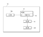
- FIG. 2 is a diagram showing functional blocks of the image inspection system designing apparatus 10 according to the present embodiment.
- the image inspection system design device 10 includes an input unit 10e, a storage unit 11, a calculation unit 13, and a display unit 10f.
- the input unit 10e receives input of information indicating the inspection content of the image inspection system 100 and information indicating the absolute size of the work 1 to be inspected by the image inspection system 100.
- the information indicating the inspection content by the image inspection system 100 may include information indicating at least one of the type, site, and state of the work 1.
- the information indicating the inspection content may be described, for example, in the form of “inspect the state X of the part B of the object A”.
- the object may be, for example, an engine block, a plastic bottle cap, a candy box, an electronic board, a chip capacitor, or the like.
- the part may be, for example, a screw hole, a top surface, a side surface, an element body, an electrode, a cutting surface, a expiration date printing, or the like.
- the state may be, for example, width, length, area, size, direction, shape, presence or absence of scratch, presence or absence of stain, presence or absence of burr, and the like.
- the image inspection system designing apparatus 10 may display the selection candidates of the object (work type), the part of the work, and the state to be inspected by the display unit 10f, and accept the selection by the input unit 10e. Thereby, even a person who does not have specialized knowledge can appropriately input the information indicating the inspection content.
- the information indicating the absolute size of the work 1 to be inspected by the image inspection system 100 may include at least one of the two-dimensional CAD data of the work 1 and the three-dimensional CAD data of the work.
- the two-dimensional CAD data of the work 1 and the three-dimensional CAD data of the work may include information indicating the dimensions of the work 1 in a predetermined unit system. Thereby, even a person who does not have specialized knowledge can easily input the information indicating the absolute dimension of the work 1.
- the input unit 10e may further accept input of information indicating the characteristics of the work 1.
- the characteristics of the work 1 may include the shape, color, material, surface treatment type, and the like of the work 1.
- the information indicating the characteristics of the work 1 may include an image of the work 1. Thus, even a person who does not have specialized knowledge can easily input the information indicating the characteristics of the work 1.
- the information indicating the characteristics of the work 1 may include a plurality of images of the work 1 taken in different directions, different distances, or under different illumination.
- the storage unit 11 stores the learning model 12.
- the learning model 12 may be a model for associating the information indicating the inspection content, the information indicating the absolute size, and the information indicating the characteristics of the work 1 with the parameters of the devices configuring the image inspection system 100.
- the learning model 12 may be configured by a neural network as described later. However, the learning model 12 may be configured by a database that accumulates past cases, or may be a model such as a binary tree or a support vector machine.
- the calculation unit 13 inputs the information indicating the inspection content and the information indicating the absolute size to the learning model 12 generated based on the past cases, and based on the output of the learning model 12, the devices configuring the image inspection system 100. Calculate the parameters of.
- the calculation unit 13 may be configured by a neural network as described later.
- the information indicating the inspection content by the image inspection system 100 and the information indicating the absolute size of the work 1 to be inspected by the image inspection system 100 are input.
- the parameters of the devices that make up the image inspection system 100 can be calculated, and even a person who does not have specialized knowledge can design the image inspection system 100. Further, it is possible to calculate the parameters of the devices forming the image inspection system 100 according to the characteristics of the work 1.
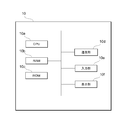
- FIG. 3 is a diagram showing a physical configuration of the image inspection system design device 10 according to the present embodiment.
- the image inspection system designing device 10 includes a CPU (Central Processing Unit) 10a corresponding to a computing device, a RAM (Random Access Memory) 10b corresponding to the storage unit 11, and a ROM (Read only Memory) 10c corresponding to the storage unit 11. And a communication unit 10d, an input unit 10e, and a display unit 10f. These respective configurations are connected to each other via a bus so that data can be transmitted and received.
- the image inspection system designing device 10 is configured by one computer will be described, but the image inspection system designing device 10 may be realized by using a plurality of computers.
- the CPU 10a is a control unit that controls the execution of programs stored in the RAM 10b or the ROM 10c, calculates data, and processes the data.
- the CPU 10a inputs the information indicating the inspection content and the information indicating the absolute size to the learning model 12, executes the calculation by the learning model 12, and based on the output of the learning model 12, the parameters of the devices configuring the image inspection system 100. It is an arithmetic unit that executes a program (image inspection system design program) for calculating
- the CPU 10a receives various input data from the input unit 10e and the communication unit 10d, displays the calculation result on the display unit 10f, and stores the calculation result in the RAM 10b and the ROM 10c.
- the RAM 10b is a data rewritable one in the storage unit 11, and may be composed of, for example, a semiconductor storage element.
- the RAM 10b stores data such as the image inspection system design program executed by the CPU 10a and the learning model 12.
- the ROM 10c can read data from the storage unit 11, and may be composed of, for example, a semiconductor storage element.
- the ROM 10c stores, for example, an image inspection system design program and data that is not rewritten.
- the communication unit 10d is an interface that connects the image inspection system design device 10 to an external device.
- the communication unit 10d may be an interface of the Internet or a LAN (Local Area Network).
- the input unit 10e receives data input from the user, and may include, for example, a keyboard, a mouse, and a touch panel.
- the display unit 10f is for visually displaying the calculation result by the CPU 10a, and may be configured by, for example, an LCD (Liquid Crystal Display).
- the image inspection system design program may be provided by being stored in a computer-readable storage medium such as the RAM 10b or the ROM 10c, or may be provided via a communication network connected by the communication unit 10d.
- the CPU 10a executes the image inspection system design program, whereby the operations of the learning model 12 and the calculation unit 13 described with reference to FIG. 2 are realized.
- the image inspection system design device 10 may include an LSI (Large-Scale Integration) in which the CPU 10a and the RAM 10b and the ROM 10c are integrated.
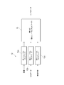
- FIG. 4 is a diagram showing an example of data input to and output from the image inspection system designing apparatus 10 according to the present embodiment.
- the learning model 12 of the image inspection system design device 10 according to the present embodiment includes a first neural network 12a, a second neural network 12b, and a third neural network 12c.
- the calculation unit 13 also includes a fourth neural network.
- the learning model 12 includes a first neural network 12a that identifies the characteristics of the work 1 based on the image of the work 1.
- the first neural network 12a inputs the image of the work 1 by using the learning data including the image of the work 1 and the information indicating the characteristics of the work 1 such as the shape, color, material and surface treatment type of the work 1.
- the learned neural network that has been learned so as to output the information representing the characteristic of the appropriate work 1 when it is output.
- the learning model 12 includes a second neural network 12b that identifies the absolute size of the work 1 based on at least one of the two-dimensional CAD data and the three-dimensional CAD data of the work 1.
- the second neural network 12b uses the learning data including at least one of the two-dimensional CAD data and the three-dimensional CAD data of the work 1 and the numerical information indicating the absolute dimension of the work 1 and the two-dimensional CAD data of the work 1 It may be a learned neural network that has been learned so as to output information that represents an appropriate absolute dimension of the work 1 when at least one of the three-dimensional CAD data is input.
- the absolute size of the work 1 is identified from at least one of the two-dimensional CAD data and the three-dimensional CAD data, and the parameters of the devices constituting the image inspection system 100 are set to the absolute size of the work 1. Can be calculated accordingly.
- the learning model 12 includes a third neural network 12c that identifies the item of the inspection content from the information indicating the inspection content.
- the third neural network 12c uses the learning data including the information indicating the inspection content described in the format “inspect the state X of the part B of the object A” and the items indicating the object, the part, and the state, It may be a learned neural network that has been learned to output an item of appropriate inspection content when information indicating the inspection content is input.
- the third neural network 12bc the item of the inspection content can be identified from the information indicating the inspection content, and the parameters of the devices configuring the image inspection system 100 can be calculated according to the inspection content.
- the calculation unit 13 receives the output of the first neural network 12a, the output of the second neural network 12b, and the output of the third neural network 12c as an input, and outputs a fourth neural network that outputs the parameters of the devices configuring the image inspection system 100. Including.
- the fourth neural network outputs the output of the first neural network 12a when an image of the workpiece 1 is input, and the second neural network when at least one of the two-dimensional CAD data of the workpiece 1 and the three-dimensional CAD data of the workpiece is input.
- the fourth neural network outputs parameters indicating the arrangement and optical characteristics of the devices that make up the image inspection system 100. In this way, the parameters of the devices that make up the image inspection system 100 can be calculated, and even a person without specialized knowledge can design the image inspection system 100.
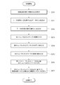
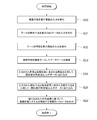
- FIG. 5 is a flowchart of a parameter calculation process executed by the image inspection system design device 10 according to this embodiment.
- the image inspection system designing device 10 receives an input of information indicating the inspection content (S10). Further, the image inspection system design device 10 accepts the input of CAD data representing the absolute size of the work 1 (S11). Further, the image inspection system designing device 10 receives an input of an image representing the characteristics of the work 1 (S12). The order of accepting the input of these pieces of information is arbitrary.
- the image inspection system design device 10 inputs an image to the first neural network 12a (S13), CAD data to the second neural network 12b (S14), and inputs inspection contents to the third neural network 12c (S15). ). Then, the image inspection system design device 10 inputs the output of the first neural network 12a, the output of the second neural network 12b, and the output of the third neural network 12c to the fourth neural network (S16).
- the image inspection system designing device 10 calculates the parameters of the devices forming the image inspection system 100 based on the output of the fourth neural network (S17). With the above, the parameter calculation process is completed.
- FIG. 6 is a flowchart of a parameter calculation process executed by the image inspection system design device 10 according to the modified example of this embodiment.
- the learning model 12 of the image inspection system designing apparatus 10 stores a database in which information indicating inspection contents and information indicating absolute dimensions are associated with parameters of devices included in the image inspection system 100. Including.
- the database includes a table that associates objects (types of work 1), parts of work 1, conditions to be inspected, absolute dimensions of work 1 and images of work 1 with parameters of devices that configure image inspection system 100. Good.
- the image inspection system designing device 10 receives an input of information indicating the inspection content (S20). Further, the image inspection system designing device 10 accepts input of CAD data representing the absolute size of the work 1 (S21). Further, the image inspection system designing device 10 receives an input of an image representing the characteristics of the work 1 (S22). The order of accepting the input of these pieces of information is arbitrary.
- the image inspection system design device 10 searches the database using the inspection content as a search key (S23).
- the image inspection system design device 10 searches for past cases that completely match the items of the inspection content input as a search key, searches for past cases that partially match, or searches for similar past cases. You can do it.
- the image inspection system designing apparatus 10 compares the input image with the image included in the search result, and narrows down the data whose similarity is a predetermined value or more (S24).
- the past cases in which the inspection content is extracted as the search key include the image of the work 1.
- the image inspection system design device 10 may calculate the similarity between the input image and the extracted images of the past cases, and narrow down the search results to, for example, data whose similarity is the upper predetermined ratio.
- the image inspection system designing device 10 compares the input absolute size with the absolute size included in the search result, and narrows down the data whose similarity is equal to or more than a predetermined value (S25).
- the search result narrowed down using the image includes the absolute size of the work 1.
- the image inspection system designing apparatus 10 calculates the similarity between the input absolute size and the extracted absolute size of the past case, and narrows down the search result to, for example, data whose similarity is the upper predetermined ratio. Good.
- the image inspection system designing device 10 calculates the parameters of the devices constituting the image inspection system 100 based on the narrowed-down search results (S26).
- the image inspection system design apparatus 10 may calculate the parameters of the devices included in the image inspection system 100, for example, by averaging the parameters of the devices included in the narrowed-down search results. In this way, by searching the database, it is possible to calculate the parameters of the devices configuring the image inspection system 100 with a relatively small amount of calculation.
- the parameter calculation process executed by the image inspection system designing apparatus 10 according to the modified example of the present embodiment ends.
- An input unit (10e) that receives input of information indicating the inspection content of the image inspection system (100) and information indicating the absolute size of the workpiece (1) to be inspected by the image inspection system (100), Information indicating the inspection content and information indicating the absolute size are input to a learning model (12) generated based on past cases, and the image inspection system (100) is input based on the output of the learning model (12). ), a calculation unit (13) for calculating the parameters of the devices constituting An image inspection system designing device (10) comprising:
- 10... Image inspection system design device 10a... CPU, 10b... RAM, 10c... ROM, 10d... Communication part, 10e... Input part, 10f... Display part, 11... Storage part, 12... Learning model, 12a ... 1st neural network, 12b... 2nd neural network, 12c... 3rd neural network, 13... Calculation part, 21... 1st illumination, 22... 2nd illumination, 31... Lens, 32... Camera, 100... Image inspection system
Landscapes
- Engineering & Computer Science (AREA)
- Computer Vision & Pattern Recognition (AREA)
- Physics & Mathematics (AREA)
- General Physics & Mathematics (AREA)
- Theoretical Computer Science (AREA)
- Image Analysis (AREA)
- Length Measuring Devices By Optical Means (AREA)
Abstract
専門知識を有さない者であっても画像検査システムの設計が行えるように支援する画像検査システム設計装置、画像検査システム設計方法及び画像検査システム設計プログラムを提供する。画像検査システム設計装置10は、画像検査システム100による検査内容を表す情報と、画像検査システム100による検査の対象となるワーク1の絶対寸法を表す情報との入力を受け付ける入力部10eと、過去の事例に基づいて生成された学習モデル12に検査内容を表す情報及び絶対寸法を表す情報を入力し、学習モデル12の出力に基づいて、画像検査システム100を構成する機器のパラメータを算出する算出部13と、を備える。
Description
本発明は、画像検査システム設計装置、画像検査システム設計方法及び画像検査システム設計プログラムに関する。
従来、製品の製造ラインに画像検査システムを導入して、部品や完成品の検品を行うことがある。この場合、対象物の状態を適切に撮影できるように、照明、レンズ及びカメラを含む機器の配置や光学特性を設計する必要がある。
例えば下記特許文献1には、被写体を照明する光源及び1ライン単位に撮像する光学系と撮像素子を備えた走行体と、走行体が1方向に走査して被写体の2次元画像を入力する画像入力手段と、を有するシミュレーション装置が記載されている。シミュレーション装置は、被写体の光学特性を示す理想画像を対象として画像入力条件を設定し、設定された信号処理条件で理想画像を用いて信号を算出し、設定された信号処理条件で信号処理された画像信号を生成する。
特許文献1に記載の技術によれば、画像入力装置に関して、光学系、機械系、電気系及び信号処理系を統合的にシミュレーションし、製品開発の試作回数を少なくして、製品化における開発期間及びコストを削減することができる。
しかしながら、画像検査システムは、使用される現場毎に照明の位置や種類を調整したり、レンズやカメラの位置や種類を選定したりする必要がある。そのため、従来、画像検査システムを使用する場合には、専門の作業員が独自のノウハウに基づいて画像検査システムの設計を行うことがある。そのような専門知識を有する人材は確保が難しく、画像検査システムを導入する障壁となることがあった。
そこで、本発明は、専門知識を有さない者であっても画像検査システムの設計が行えるように支援する画像検査システム設計装置、画像検査システム設計方法及び画像検査システム設計プログラムを提供する。
本開示の一態様に係る画像検査システム設計装置は、画像検査システムによる検査内容を表す情報と、画像検査システムによる検査の対象となるワークの絶対寸法を表す情報との入力を受け付ける入力部と、過去の事例に基づいて生成された学習モデルに検査内容を表す情報及び絶対寸法を表す情報を入力し、学習モデルの出力に基づいて、画像検査システムを構成する機器のパラメータを算出する算出部と、を備える。
この態様によれば、画像検査システムによる検査内容を表す情報と、画像検査システムによる検査の対象となるワークの絶対寸法を表す情報とを入力することで、画像検査システムを構成する機器のパラメータを算出することができ、専門知識を有さない者であっても画像検査システムの設計が行える。
上記態様において、入力部は、ワークの特性を表す情報の入力をさらに受け付け、学習モデルは、検査内容を表す情報、絶対寸法を表す情報及びワークの特性を表す情報と、パラメータとを関係付けるモデルであってよい。
この態様によれば、画像検査システムを構成する機器のパラメータをワークの特性に応じて算出することができる。
上記態様において、ワークの特性を表す情報は、ワークを撮影した画像を含んでよい。
この態様によれば、専門知識を有さない者であっても、ワークの特性を表す情報を容易に入力することができる。
上記態様において、学習モデルは、画像に基づいてワークの特性を識別する第1ニューラルネットワークを含んでよい。
この態様によれば、ワークを撮影した画像からワークの特性を識別し、画像検査システムを構成する機器のパラメータをワークの特性に応じて算出することができる。
上記態様において、絶対寸法を表す情報は、ワークの2次元CADデータ及びワークの3次元CADデータの少なくともいずれかを含んでよい。
この態様によれば、専門知識を有さない者であっても、ワークの絶対寸法を表す情報を容易に入力することができる。
上記態様において、学習モデルは、2次元CADデータ及び3次元CADデータの少なくともいずれかに基づいてワークの絶対寸法を識別する第2ニューラルネットワークを含んでよい。
この態様によれば、2次元CADデータ及び3次元CADデータの少なくともいずれかからワークの絶対寸法を識別し、画像検査システムを構成する機器のパラメータをワークの絶対寸法に応じて算出することができる。
上記態様において、検査内容を表す情報は、ワークの種類、部位及び状態の少なくともいずれかを表す情報を含んでよい。
この態様によれば、専門知識を有さない者であっても、検査内容を表す情報を適切に入力することができる。
上記態様において、学習モデルは、検査内容を表す情報から検査内容の項目を識別する第3ニューラルネットワークを含んでよい。
この態様によれば、検査内容を表す情報から検査内容の項目を識別し、画像検査システムを構成する機器のパラメータを検査内容に応じて算出することができる。
上記態様において、学習モデルは、検査内容を表す情報及び絶対寸法を表す情報と、パラメータとを対応付けたデータベースを含んでよい。
この態様によれば、比較的少ない演算量で画像検査システムを構成する機器のパラメータを算出することができる。
本開示の他の態様に係る画像検査システム設計方法は、画像検査システムによる検査内容を表す情報と、画像検査システムによる検査の対象となるワークの絶対寸法を表す情報との入力を受け付けることと、過去の事例に基づいて生成された学習モデルに検査内容を表す情報及び絶対寸法を表す情報を入力し、学習モデルの出力に基づいて、画像検査システムを構成する機器のパラメータを算出することと、を含む。
この態様によれば、画像検査システムによる検査内容を表す情報と、画像検査システムによる検査の対象となるワークの絶対寸法を表す情報とを入力することで、画像検査システムを構成する機器のパラメータを算出することができ、専門知識を有さない者であっても画像検査システムの設計が行える。
本開示の他の態様に係る画像検査システム設計プログラムは、画像検査システムによる検査内容を表す情報と、画像検査システムによる検査の対象となるワークの絶対寸法を表す情報との入力を受け付ける入力部を備える画像検査システム設計装置に備えられたプロセッサを、過去の事例に基づいて生成された学習モデルに検査内容を表す情報及び絶対寸法を表す情報を入力し、学習モデルの出力に基づいて、画像検査システムを構成する機器のパラメータを算出する算出部、として機能させる。
この態様によれば、画像検査システムによる検査内容を表す情報と、画像検査システムによる検査の対象となるワークの絶対寸法を表す情報とを入力することで、画像検査システムを構成する機器のパラメータを算出することができ、専門知識を有さない者であっても画像検査システムの設計が行える。
本発明によれば、専門知識を有さない者であっても画像検査システムの設計が行えるように支援する画像検査システム設計装置、画像検査システム設計方法及び画像検査システム設計プログラムを提供することができる。
添付図面を参照して、本発明の実施形態について説明する。なお、各図において、同一の符号を付したものは、同一又は同様の構成を有する。
図1は、本発明の実施形態に係る画像検査システム設計装置10により設計される画像検査システム100の概要を示す図である。画像検査システム100は、カメラ32により撮影されたワーク1の画像に基づいて、ワーク1の検査を行うシステムである。なお、図1に示す画像検査システム100は一例であり、画像検査システム100は、図示していない任意の機器を含んでもよいし、図示した機器の一部を含まなくてもよい。
画像検査システム100は、第1照明21、第2照明22、レンズ31及びカメラ32を含む。第1照明21は、カメラからd1の距離かつワーク1からd2の距離に固定され、光Lをワーク1に投光する。第2照明22は、破線で示す基準軸から角度θ傾けて固定され、ワーク1に投光する。第1照明21及び第2照明22により照射された光は、ワーク1で反射され、反射光Rがレンズ31に入射する。カメラ32は、レンズ31により集光された反射光Rを撮影する。
このような画像検査システム100によりワーク1の画像検査を行う場合、カメラ32から第1照明21までの距離d1、ワーク1から第1照明21までの距離d2、第2照明22の取付角度θ、レンズ31の焦点距離及びF値並びにカメラ32の解像度及び感度といったパラメータを設計する必要がある。本明細書では、第1照明21、第2照明22、レンズ31及びカメラ32を機器と総称し、画像検査を行うために決定すべき距離d1、距離d2、角度θ、第1照明21及び第2照明22の形状、光量及び光の色、レンズ31の焦点距離及びF値並びにカメラ32の解像度及び感度を機器のパラメータと総称する。なお、画像検査システム100は、任意の機器を含んでよく、機器のパラメータは、機器の位置、姿勢及び光学特性を特定する量を含んでよい。
図2は、本実施形態に係る画像検査システム設計装置10の機能ブロックを示す図である。画像検査システム設計装置10は、入力部10e、記憶部11、算出部13及び表示部10fを備える。
入力部10eは、画像検査システム100による検査内容を表す情報と、画像検査システム100による検査の対象となるワーク1の絶対寸法を表す情報との入力を受け付ける。ここで、画像検査システム100による検査内容を表す情報は、ワーク1の種類、部位及び状態の少なくともいずれかを表す情報を含んでよい。
検査内容を表す情報は、例えば、「オブジェクトAの部位Bの状態Xを検査する」という形式で記述されてよい。ここで、オブジェクトは、例えば、エンジンブロック、ペットボトルキャップ、お菓子箱、電子基板及びチップコンデンサ等であってよい。また、部位は、例えば、ネジ穴、天面、側面、素体、電極、切削面及び賞味期限印字等であってよい。状態は、例えば、幅、長さ、面積、大きさ、方向、形状、傷の有無、汚れの有無及びバリの有無等であってよい。画像検査システム設計装置10は、表示部10fによって、オブジェクト(ワークの種類)、ワークの部位及び検査対象とする状態の選択候補を表示して、入力部10eによって選択を受け付けてもよい。これにより、専門知識を有さない者であっても、検査内容を表す情報を適切に入力することができる。
画像検査システム100による検査の対象となるワーク1の絶対寸法を表す情報は、ワーク1の2次元CADデータ及びワークの3次元CADデータの少なくともいずれかを含んでよい。ワーク1の2次元CADデータ及びワークの3次元CADデータは、ワーク1の寸法を所定の単位系で示す情報を含んでいてよい。これにより、専門知識を有さない者であっても、ワーク1の絶対寸法を表す情報を容易に入力することができる。
入力部10eは、ワーク1の特性を表す情報の入力をさらに受け付けてよい。ここで、ワーク1の特性は、ワーク1の形状、色、材質及び表面処理の種類等を含んでよい。ワーク1の特性を表す情報は、ワーク1を撮影した画像を含んでよい。これにより、専門知識を有さない者であっても、ワーク1の特性を表す情報を容易に入力することができる。なお、ワーク1の特性を表す情報は、ワーク1を異なる方向、異なる距離又は異なる照明下で撮影した複数の画像を含んでよい。
記憶部11は、学習モデル12を記憶する。学習モデル12は、検査内容を表す情報、絶対寸法を表す情報及びワーク1の特性を表す情報と、画像検査システム100を構成する機器のパラメータとを関係付けるモデルであってよい。学習モデル12は、後述するように、ニューラルネットワークによって構成されてよい。もっとも、学習モデル12は、過去の事例を蓄積したデータベースによって構成されてもよいし、二分木やサポートベクターマシン等のモデルであってもよい。
算出部13は、過去の事例に基づいて生成された学習モデル12に検査内容を表す情報及び絶対寸法を表す情報を入力し、学習モデル12の出力に基づいて、画像検査システム100を構成する機器のパラメータを算出する。算出部13は、後述するように、ニューラルネットワークによって構成されてよい。
本実施形態に係る画像検査システム設計装置10によれば、画像検査システム100による検査内容を表す情報と、画像検査システム100による検査の対象となるワーク1の絶対寸法を表す情報とを入力することで、画像検査システム100を構成する機器のパラメータを算出することができ、専門知識を有さない者であっても画像検査システム100の設計が行える。また、画像検査システム100を構成する機器のパラメータをワーク1の特性に応じて算出することができる。
図3は、本実施形態に係る画像検査システム設計装置10の物理的構成を示す図である。画像検査システム設計装置10は、演算装置に相当するCPU(Central Processing Unit)10aと、記憶部11に相当するRAM(Random Access Memory)10bと、記憶部11に相当するROM(Read only Memory)10cと、通信部10dと、入力部10eと、表示部10fとを有する。これらの各構成は、バスを介して相互にデータ送受信可能に接続される。なお、本例では画像検査システム設計装置10が一台のコンピュータで構成される場合について説明するが、画像検査システム設計装置10は、複数のコンピュータを用いて実現されてもよい。
CPU10aは、RAM10b又はROM10cに記憶されたプログラムの実行に関する制御やデータの演算、加工を行う制御部である。CPU10aは、学習モデル12に検査内容を表す情報及び絶対寸法を表す情報を入力し、学習モデル12による演算を実行し、学習モデル12の出力に基づいて、画像検査システム100を構成する機器のパラメータを算出するプログラム(画像検査システム設計プログラム)を実行する演算装置である。CPU10aは、入力部10eや通信部10dから種々の入力データを受け取り、演算結果を表示部10fに表示したり、RAM10bやROM10cに格納したりする。
RAM10bは、記憶部11のうちデータの書き換えが可能なものであり、例えば半導体記憶素子で構成されてよい。RAM10bは、CPU10aが実行する画像検査システム設計プログラムや、学習モデル12といったデータを記憶する。
ROM10cは、記憶部11のうちデータの読み出しが可能なものであり、例えば半導体記憶素子で構成されてよい。ROM10cは、例えば画像検査システム設計プログラムや、書き換えが行われないデータを記憶する。
通信部10dは、画像検査システム設計装置10を外部機器に接続するインターフェースである。通信部10dは、インターネットやLAN(Local Area Network)のインターフェースであってよい。
入力部10eは、ユーザからデータの入力を受け付けるものであり、例えば、キーボード、マウス及びタッチパネルを含んでよい。
表示部10fは、CPU10aによる演算結果を視覚的に表示するものであり、例えば、LCD(Liquid Crystal Display)により構成されてよい。
画像検査システム設計プログラムは、RAM10bやROM10c等のコンピュータによって読み取り可能な記憶媒体に記憶されて提供されてもよいし、通信部10dにより接続される通信ネットワークを介して提供されてもよい。画像検査システム設計装置10では、CPU10aが画像検査システム設計プログラムを実行することにより、図2を用いて説明した学習モデル12及び算出部13の動作が実現される。なお、これらの物理的な構成は例示であって、必ずしも独立した構成でなくてもよい。例えば、画像検査システム設計装置10は、CPU10aとRAM10bやROM10cが一体化したLSI(Large-Scale Integration)を備えていてもよい。
図4は、本実施形態に係る画像検査システム設計装置10に入力されるデータと、出力されるデータの一例を示す図である。同図に示すように、本実施形態に係る画像検査システム設計装置10の学習モデル12は、第1ニューラルネットワーク12a、第2ニューラルネットワーク12b及び第3ニューラルネットワーク12cを含む。また、算出部13は、第4ニューラルネットワークを含む。
学習モデル12は、ワーク1の画像に基づいてワーク1の特性を識別する第1ニューラルネットワーク12aを含む。第1ニューラルネットワーク12aは、ワーク1の画像と、ワーク1の形状、色、材質及び表面処理の種類等のワーク1の特性を表す情報とを含む学習データを用いて、ワーク1の画像が入力された場合に、適切なワーク1の特性を表す情報を出力するように学習された、学習済みのニューラルネットワークであってよい。第1ニューラルネットワーク12aを用いることで、ワーク1を撮影した画像からワーク1の特性を識別し、画像検査システム100を構成する機器のパラメータをワーク1の特性に応じて算出することができる。
学習モデル12は、ワーク1の2次元CADデータ及び3次元CADデータの少なくともいずれかに基づいてワーク1の絶対寸法を識別する第2ニューラルネットワーク12bを含む。第2ニューラルネットワーク12bは、ワーク1の2次元CADデータ及び3次元CADデータの少なくともいずれかと、ワーク1の絶対寸法を表す数値情報とを含む学習データを用いて、ワーク1の2次元CADデータ及び3次元CADデータの少なくともいずれかが入力された場合に、適切なワーク1の絶対寸法を表す情報を出力するように学習された、学習済みのニューラルネットワークであってよい。第2ニューラルネットワーク12bを用いることで、2次元CADデータ及び3次元CADデータの少なくともいずれかからワーク1の絶対寸法を識別し、画像検査システム100を構成する機器のパラメータをワーク1の絶対寸法に応じて算出することができる。
学習モデル12は、検査内容を表す情報から検査内容の項目を識別する第3ニューラルネットワーク12cを含む。第3ニューラルネットワーク12cは、「オブジェクトAの部位Bの状態Xを検査する」という形式で記載された検査内容を表す情報と、オブジェクト、部位及び状態を表す項目とを含む学習データを用いて、検査内容を表す情報が入力された場合に、適切な検査内容の項目を出力するように学習された、学習済みのニューラルネットワークであってよい。第3ニューラルネットワーク12bcを用いることで、検査内容を表す情報から検査内容の項目を識別し、画像検査システム100を構成する機器のパラメータを検査内容に応じて算出することができる。
算出部13は、第1ニューラルネットワーク12aの出力、第2ニューラルネットワーク12bの出力及び第3ニューラルネットワーク12cの出力を入力として、画像検査システム100を構成する機器のパラメータを出力する第4ニューラルネットワークを含む。第4ニューラルネットワークは、ワーク1を撮影した画像を入力した場合の第1ニューラルネットワーク12aの出力、ワーク1の2次元CADデータ及びワークの3次元CADデータの少なくともいずれかを入力した場合の第2ニューラルネットワーク12bの出力及び画像検査システム100による検査内容を表す情報を入力した場合の第3ニューラルネットワーク12cの出力と、画像検査システム100を構成する機器のパラメータとを含む学習データを用いて、第1ニューラルネットワーク12aの出力、第2ニューラルネットワーク12bの出力及び第3ニューラルネットワーク12cの出力が入力された場合に、適切な機器のパラメータを出力するように学習された、学習済みのニューラルネットワークであってよい。第4ニューラルネットワークは、画像検査システム100を構成する機器の配置や光学特性を表すパラメータを出力する。このようにして、画像検査システム100を構成する機器のパラメータを算出することができ、専門知識を有さない者であっても画像検査システム100の設計が行える。
図5は、本実施形態に係る画像検査システム設計装置10により実行されるパラメータ算出処理のフローチャートである。はじめに、画像検査システム設計装置10は、検査内容を表す情報の入力を受け付ける(S10)。また、画像検査システム設計装置10は、ワーク1の絶対寸法を表すCADデータの入力を受け付ける(S11)。また、画像検査システム設計装置10は、ワーク1の特性を表す画像の入力を受け付ける(S12)。なお、これらの情報の入力を受け付ける順序は任意である。
画像検査システム設計装置10は、第1ニューラルネットワーク12aに画像を入力し(S13)、第2ニューラルネットワーク12bにCADデータを入力し(S14)、第3ニューラルネットワーク12cに検査内容を入力する(S15)。そして、画像検査システム設計装置10は、第1ニューラルネットワーク12aの出力、第2ニューラルネットワーク12bの出力及び第3ニューラルネットワーク12cの出力を、第4ニューラルネットワークに入力する(S16)。
最後に、画像検査システム設計装置10は、第4ニューラルネットワークの出力に基づいて、画像検査システム100を構成する機器のパラメータを算出する(S17)。以上により、パラメータ算出処理が終了する。
図6は、本実施形態の変形例に係る画像検査システム設計装置10により実行されるパラメータ算出処理のフローチャートである。本実施形態の変形例に係る画像検査システム設計装置10の学習モデル12は、検査内容を表す情報及び絶対寸法を表す情報と、画像検査システム100を構成する機器のパラメータとを対応付けたデータベースを含む。データベースは、オブジェクト(ワーク1の種類)、ワーク1の部位、検査対象とする状態、ワーク1の絶対寸法及びワーク1の画像と、画像検査システム100を構成する機器のパラメータとを対応付けるテーブルを含んでよい。
はじめに、画像検査システム設計装置10は、検査内容を表す情報の入力を受け付ける(S20)。また、画像検査システム設計装置10は、ワーク1の絶対寸法を表すCADデータの入力を受け付ける(S21)。また、画像検査システム設計装置10は、ワーク1の特性を表す画像の入力を受け付ける(S22)。なお、これらの情報の入力を受け付ける順序は任意である。
画像検査システム設計装置10は、検査内容を検索キーとしてデータベースを検索する(S23)。画像検査システム設計装置10は、検索キーとして入力された検査内容の項目に完全一致する過去の事例を検索したり、部分一致する過去の事例を検索したり、類似する過去の事例を検索したりしてよい。
次に、画像検査システム設計装置10は、入力された画像と検索結果に含まれる画像を比較して、類似度が所定値以上のデータに絞り込みを行う(S24)。検査内容を検索キーとして抽出した過去の事例は、ワーク1の画像を含む。画像検査システム設計装置10は、入力された画像と、抽出された過去の事例の画像との類似度を算出し、検索結果を、例えば、類似度が上位所定割合であるデータに絞り込んでよい。
その後、画像検査システム設計装置10は、入力された絶対寸法と検索結果に含まれる絶対寸法を比較して、類似度が所定値以上のデータに絞り込みを行う(S25)。画像を用いて絞り込まれた検索結果は、ワーク1の絶対寸法を含む。画像検査システム設計装置10は、入力された絶対寸法と、抽出された過去の事例の絶対寸法との類似度を算出し、検索結果を、例えば、類似度が上位所定割合であるデータに絞り込んでよい。
最後に、画像検査システム設計装置10は、絞り込まれた検索結果に基づいて、画像検査システム100を構成する機器のパラメータを算出する(S26)。画像検査システム設計装置10は、例えば、絞り込まれた検索結果に含まれる機器のパラメータの平均によって、画像検査システム100を構成する機器のパラメータを算出してよい。このように、データベースの検索によって、比較的少ない演算量で画像検査システム100を構成する機器のパラメータを算出することができる。以上により、本実施形態の変形例に係る画像検査システム設計装置10により実行されるパラメータ算出処理が終了する。
以上説明した実施形態は、本発明の理解を容易にするためのものであり、本発明を限定して解釈するためのものではない。実施形態が備える各要素並びにその配置、材料、条件、形状及びサイズ等は、例示したものに限定されるわけではなく適宜変更することができる。また、異なる実施形態で示した構成同士を部分的に置換し又は組み合わせることが可能である。
[附記]
画像検査システム(100)による検査内容を表す情報と、前記画像検査システム(100)による検査の対象となるワーク(1)の絶対寸法を表す情報との入力を受け付ける入力部(10e)と、
過去の事例に基づいて生成された学習モデル(12)に前記検査内容を表す情報及び前記絶対寸法を表す情報を入力し、前記学習モデル(12)の出力に基づいて、前記画像検査システム(100)を構成する機器のパラメータを算出する算出部(13)と、
を備える画像検査システム設計装置(10)。
画像検査システム(100)による検査内容を表す情報と、前記画像検査システム(100)による検査の対象となるワーク(1)の絶対寸法を表す情報との入力を受け付ける入力部(10e)と、
過去の事例に基づいて生成された学習モデル(12)に前記検査内容を表す情報及び前記絶対寸法を表す情報を入力し、前記学習モデル(12)の出力に基づいて、前記画像検査システム(100)を構成する機器のパラメータを算出する算出部(13)と、
を備える画像検査システム設計装置(10)。
1…ワーク、10…画像検査システム設計装置、10a…CPU、10b…RAM、10c…ROM、10d…通信部、10e…入力部、10f…表示部、11…記憶部、12…学習モデル、12a…第1ニューラルネットワーク、12b…第2ニューラルネットワーク、12c…第3ニューラルネットワーク、13…算出部、21…第1照明、22…第2照明、31…レンズ、32…カメラ、100…画像検査システム
Claims (11)
- 画像検査システムによる検査内容を表す情報と、前記画像検査システムによる検査の対象となるワークの絶対寸法を表す情報との入力を受け付ける入力部と、
過去の事例に基づいて生成された学習モデルに前記検査内容を表す情報及び前記絶対寸法を表す情報を入力し、前記学習モデルの出力に基づいて、前記画像検査システムを構成する機器のパラメータを算出する算出部と、
を備える画像検査システム設計装置。 - 前記入力部は、前記ワークの特性を表す情報の入力をさらに受け付け、
前記学習モデルは、前記検査内容を表す情報、前記絶対寸法を表す情報及び前記ワークの特性を表す情報と、前記パラメータとを関係付けるモデルである、
請求項1に記載の画像検査システム設計装置。 - 前記ワークの特性を表す情報は、前記ワークを撮影した画像を含む、
請求項2に記載の画像検査システム設計装置。 - 前記学習モデルは、前記画像に基づいて前記ワークの特性を識別する第1ニューラルネットワークを含む、
請求項3に記載の画像検査システム設計装置。 - 前記絶対寸法を表す情報は、前記ワークの2次元CADデータ及び前記ワークの3次元CADデータの少なくともいずれかを含む、
請求項1から4のいずれか一項に記載の画像検査システム設計装置。 - 前記学習モデルは、前記2次元CADデータ及び前記3次元CADデータの少なくともいずれかに基づいて前記ワークの絶対寸法を識別する第2ニューラルネットワークを含む、
請求項5に記載の画像検査システム設計装置。 - 前記検査内容を表す情報は、前記ワークの種類、部位及び状態の少なくともいずれかを表す情報を含む、
請求項1から6のいずれか一項に記載の画像検査システム設計装置。 - 前記学習モデルは、前記検査内容を表す情報から検査内容の項目を識別する第3ニューラルネットワークを含む、
請求項7に記載の画像検査システム設計装置。 - 前記学習モデルは、前記検査内容を表す情報及び前記絶対寸法を表す情報と、前記パラメータとを対応付けたデータベースを含む、
請求項1から8のいずれか一項に記載の画像検査システム設計装置。 - 画像検査システムによる検査内容を表す情報と、前記画像検査システムによる検査の対象となるワークの絶対寸法を表す情報との入力を受け付けることと、
過去の事例に基づいて生成された学習モデルに前記検査内容を表す情報及び前記絶対寸法を表す情報を入力し、前記学習モデルの出力に基づいて、前記画像検査システムを構成する機器のパラメータを算出することと、
を含む画像検査システム設計方法。 - 画像検査システムによる検査内容を表す情報と、前記画像検査システムによる検査の対象となるワークの絶対寸法を表す情報との入力を受け付ける入力部を備える画像検査システム設計装置に備えられたプロセッサを、
過去の事例に基づいて生成された学習モデルに前記検査内容を表す情報及び前記絶対寸法を表す情報を入力し、前記学習モデルの出力に基づいて、前記画像検査システムを構成する機器のパラメータを算出する算出部、
として機能させる画像検査システム設計プログラム。
Priority Applications (1)
| Application Number | Priority Date | Filing Date | Title |
|---|---|---|---|
| CN201980058215.XA CN112655017A (zh) | 2018-12-26 | 2019-12-09 | 图像检查系统设计装置、图像检查系统设计方法以及图像检查系统设计程序 |
Applications Claiming Priority (2)
| Application Number | Priority Date | Filing Date | Title |
|---|---|---|---|
| JP2018-242927 | 2018-12-26 | ||
| JP2018242927A JP2020106936A (ja) | 2018-12-26 | 2018-12-26 | 画像検査システム設計装置、画像検査システム設計方法及び画像検査システム設計プログラム |
Publications (1)
| Publication Number | Publication Date |
|---|---|
| WO2020137488A1 true WO2020137488A1 (ja) | 2020-07-02 |
Family
ID=71129781
Family Applications (1)
| Application Number | Title | Priority Date | Filing Date |
|---|---|---|---|
| PCT/JP2019/048075 Ceased WO2020137488A1 (ja) | 2018-12-26 | 2019-12-09 | 画像検査システム設計装置、画像検査システム設計方法及び画像検査システム設計プログラム |
Country Status (3)
| Country | Link |
|---|---|
| JP (1) | JP2020106936A (ja) |
| CN (1) | CN112655017A (ja) |
| WO (1) | WO2020137488A1 (ja) |
Families Citing this family (2)
| Publication number | Priority date | Publication date | Assignee | Title |
|---|---|---|---|---|
| JP7799240B2 (ja) * | 2021-05-20 | 2026-01-15 | ブラザー工業株式会社 | 検査装置、コンピュータプログラム、および、検査方法 |
| WO2022264195A1 (ja) * | 2021-06-14 | 2022-12-22 | 株式会社日立ハイテク | コンピュータシステム、寸法計測方法、および記憶媒体 |
Citations (5)
| Publication number | Priority date | Publication date | Assignee | Title |
|---|---|---|---|---|
| JPS63201876A (ja) * | 1987-02-18 | 1988-08-19 | Hitachi Ltd | 画像処理方法および装置 |
| JPS63204373A (ja) * | 1987-02-19 | 1988-08-24 | Fuji Electric Co Ltd | 撮像用照明方法の設計支援装置 |
| JPH06229957A (ja) * | 1993-02-01 | 1994-08-19 | Fujitsu Ltd | 材質判別方法 |
| JPH07220058A (ja) * | 1991-07-12 | 1995-08-18 | Omron Corp | 照明条件設定支援装置および方法 |
| JP2019060780A (ja) * | 2017-09-27 | 2019-04-18 | ファナック株式会社 | 検査装置及び検査システム |
Family Cites Families (4)
| Publication number | Priority date | Publication date | Assignee | Title |
|---|---|---|---|---|
| US20050157920A1 (en) * | 2004-01-21 | 2005-07-21 | John Doherty | Machine vision system and method |
| US9855698B2 (en) * | 2013-08-07 | 2018-01-02 | Massachusetts Institute Of Technology | Automatic process control of additive manufacturing device |
| JP6604832B2 (ja) * | 2015-12-02 | 2019-11-13 | 池上通信機株式会社 | 機械学習支援装置 |
| KR102699826B1 (ko) * | 2016-11-16 | 2024-08-29 | 삼성전자주식회사 | 재질 인식 및 재질 트레이닝을 수행하는 방법 및 장치 |
-
2018
- 2018-12-26 JP JP2018242927A patent/JP2020106936A/ja active Pending
-
2019
- 2019-12-09 WO PCT/JP2019/048075 patent/WO2020137488A1/ja not_active Ceased
- 2019-12-09 CN CN201980058215.XA patent/CN112655017A/zh active Pending
Patent Citations (5)
| Publication number | Priority date | Publication date | Assignee | Title |
|---|---|---|---|---|
| JPS63201876A (ja) * | 1987-02-18 | 1988-08-19 | Hitachi Ltd | 画像処理方法および装置 |
| JPS63204373A (ja) * | 1987-02-19 | 1988-08-24 | Fuji Electric Co Ltd | 撮像用照明方法の設計支援装置 |
| JPH07220058A (ja) * | 1991-07-12 | 1995-08-18 | Omron Corp | 照明条件設定支援装置および方法 |
| JPH06229957A (ja) * | 1993-02-01 | 1994-08-19 | Fujitsu Ltd | 材質判別方法 |
| JP2019060780A (ja) * | 2017-09-27 | 2019-04-18 | ファナック株式会社 | 検査装置及び検査システム |
Also Published As
| Publication number | Publication date |
|---|---|
| CN112655017A (zh) | 2021-04-13 |
| JP2020106936A (ja) | 2020-07-09 |
Similar Documents
| Publication | Publication Date | Title |
|---|---|---|
| JP7316731B2 (ja) | ビジョンシステムで画像内のパターンを検出及び分類するためのシステム及び方法 | |
| TWI651687B (zh) | 三維模型建構方法及其系統 | |
| Koniar et al. | Virtual instrumentation for visual inspection in mechatronic applications | |
| EP3388985A1 (en) | Facilitating an error analysis of a product deficiency system and method | |
| CN113888735A (zh) | 船舶舾装管架模型三维标注方法、系统、设备及存储介质 | |
| JP2020106936A (ja) | 画像検査システム設計装置、画像検査システム設計方法及び画像検査システム設計プログラム | |
| Xia et al. | Large vision-language models enabled novel objects 6D pose estimation for human-robot collaboration | |
| JP2017091208A (ja) | 文書点検支援装置、文書点検支援システム及びプログラム | |
| Ho et al. | Preliminary study of Augmented Reality based manufacturing for further integration of Quality Control 4.0 supported by metrology | |
| Gao et al. | A self-projected light-section method for fast three-dimensional shape inspection | |
| Huan et al. | Efficient leather spreading operations by dual-arm robotic systems | |
| US11087218B2 (en) | Electronic device, presentation method for decision-making process module and computer readable medium | |
| JP2021009080A (ja) | 検査装置、検査システム、及び検査方法 | |
| JPS63201876A (ja) | 画像処理方法および装置 | |
| CN113811908B (zh) | 用于确定生产设备的生产周期的方法和装置 | |
| Cheng et al. | Deep learning hotspots detection with generative adversarial network-based data augmentation | |
| Huang et al. | An assembly sequence monitoring method based on workflow modeling for human–robot collaborative assembly | |
| US10782963B2 (en) | Introducing artifact information system and method | |
| López-Estrada et al. | Design and implementation of a vision system on an innovative single point micro-machining device for tool tip localization | |
| JP2021015099A (ja) | 検査対象品の欠陥検出方法、その装置及びそのコンピュータプログラム | |
| WO2020012874A1 (ja) | 画像処理装置、画像処理方法及び画像処理プログラム | |
| JP2025065927A (ja) | 画像測定機及びプログラム | |
| CN104050386B (zh) | 基于刚性体识别的三维尺寸完备性检测方法 | |
| Dayrit et al. | PCBA solder vision inspection using machine vision algorithm and optimization process | |
| Rathod et al. | Vision system with deep learning classifiers for automatic quality inspection |
Legal Events
| Date | Code | Title | Description |
|---|---|---|---|
| 121 | Ep: the epo has been informed by wipo that ep was designated in this application |
Ref document number: 19901777 Country of ref document: EP Kind code of ref document: A1 |
|
| NENP | Non-entry into the national phase |
Ref country code: DE |
|
| 122 | Ep: pct application non-entry in european phase |
Ref document number: 19901777 Country of ref document: EP Kind code of ref document: A1 |