WO2020137418A1 - 微粒子検出器 - Google Patents
微粒子検出器 Download PDFInfo
- Publication number
- WO2020137418A1 WO2020137418A1 PCT/JP2019/047608 JP2019047608W WO2020137418A1 WO 2020137418 A1 WO2020137418 A1 WO 2020137418A1 JP 2019047608 W JP2019047608 W JP 2019047608W WO 2020137418 A1 WO2020137418 A1 WO 2020137418A1
- Authority
- WO
- WIPO (PCT)
- Prior art keywords
- electrode
- fine particles
- charge
- collection
- voltage
- Prior art date
- Legal status (The legal status is an assumption and is not a legal conclusion. Google has not performed a legal analysis and makes no representation as to the accuracy of the status listed.)
- Ceased
Links
Images

Classifications
-
- G—PHYSICS
- G01—MEASURING; TESTING
- G01N—INVESTIGATING OR ANALYSING MATERIALS BY DETERMINING THEIR CHEMICAL OR PHYSICAL PROPERTIES
- G01N15/00—Investigating characteristics of particles; Investigating permeability, pore-volume or surface-area of porous materials
- G01N15/06—Investigating concentration of particle suspensions
-
- G—PHYSICS
- G01—MEASURING; TESTING
- G01N—INVESTIGATING OR ANALYSING MATERIALS BY DETERMINING THEIR CHEMICAL OR PHYSICAL PROPERTIES
- G01N27/00—Investigating or analysing materials by the use of electric, electrochemical, or magnetic means
- G01N27/62—Investigating or analysing materials by the use of electric, electrochemical, or magnetic means by investigating the ionisation of gases, e.g. aerosols; by investigating electric discharges, e.g. emission of cathode
- G01N27/68—Investigating or analysing materials by the use of electric, electrochemical, or magnetic means by investigating the ionisation of gases, e.g. aerosols; by investigating electric discharges, e.g. emission of cathode using electric discharge to ionise a gas
Definitions
- the present invention relates to a particle detector.
- a ceramic housing having a gas flow path, a charge generation unit that adds electric charges generated by electric discharge to the particles in the gas introduced into the gas flow path to form charged particles
- the gas flow path was provided with a collection unit that collects the charged fine particles on the downstream side of the charge generation unit, and a number measurement unit that measures the number of the fine particles based on the amount of charges of the collected charged fine particles.
- the thing is known (for example, refer patent document 1).
- the collection part has a collection electrode exposed in the gas flow path, and a counter electrode facing the collection electrode with the gas flow path in between.
- the collection electrode collects the charged fine particles by using an electric field generated between the collection electrode and the counter electrode in the gas flow path by a voltage applied between the collection electrode and the counter electrode.
- the amount of charge of the collected charged fine particles is detected as a minute current (for example, several pA).
- the amount of electric charge of the collected charged fine particles is detected as a minute electric current (for example, several pA), it is easily affected by noise around the collecting electrode, which makes it difficult to detect accurately.
- the present invention has been made to solve such a problem, and its main purpose is to improve the detection accuracy of fine particles.
- the particle detector of the present invention is A particle detector used to detect particles in a gas, A casing having a gas flow path through which the gas passes, A charge generation unit that adds a charge generated by discharge to the fine particles in the gas introduced into the gas flow path to form charged fine particles, A collection electrode that collects a collection target that is either the charged fine particles or the charges that are not added to the fine particles, An electric field generation electrode that is provided at a position facing the collection electrode and that generates a collection electric field that moves the collection target toward the collection electrode, An arithmetic unit that detects the fine particles based on a physical quantity that changes according to the collection target that is collected by the collection electrode, Equipped with The calculation unit, before detecting the fine particles based on the physical quantity, the discharge voltage of the charge generation unit when detecting the fine particles so that the discharge noise in the collection electrode falls within a predetermined allowable range. Determine It is a thing.
- particles in the gas are made into charged particles by the charge generation unit generating charges, and are collected toward the collecting electrode by the collecting electric field (charge particles and charges not added to the particles). And either) are moved and collected by the collecting electrode.
- the calculation unit detects the fine particles in the gas based on the physical quantity that changes according to the collection target collected by the collection electrode.
- the calculation unit determines the discharge voltage of the charge generation unit when detecting the particles so that the discharge noise at the collection electrode falls within a predetermined allowable range before detecting the particles in the gas.
- Electric charges are generated by electric discharge in the electric charge generation part, but since the surrounding environment (for example, temperature, humidity, the adhesion state of fine particles in the gas flow path, etc.) affects the electric discharge and electric charge generation, the fine particles in the gas are
- the discharge voltage is determined before detection.
- the discharge noise is noise in the collection electrode and is caused by the discharge of the charge generation section.
- the allowable range of the discharge noise is set so that the discharge noise does not affect the detection of particles by the calculation unit. By doing so, it is possible to suppress the influence of noise caused by the discharge of the charge generation unit on the detection of the fine particles, and it is possible to improve the detection accuracy of the fine particles.
- the calculation unit may determine the discharge voltage of the charge generation unit before detecting the particles in the gas each time, or may discharge the charge voltage of the charge generation unit before detecting the particles in the gas regularly or irregularly. May be determined.
- charge includes ions in addition to positive charges and negative charges.
- the “physical quantity” may be any parameter that changes based on the number of collection targets (charge quantity), and examples thereof include current.
- the calculation unit may detect the amount of the fine particles based on the physical quantity, and in that case, the amount of the fine particles may be at least one of the number, the mass, and the surface area of the fine particles. "Detecting the amount of fine particles” means not only measuring the amount of fine particles but also determining whether the amount of fine particles falls within a predetermined numerical range (for example, whether or not it exceeds a predetermined threshold value). The case shall be included.
- the calculation unit determines the discharge voltage so that the charge generation unit generates an amount of charge that exceeds a minimum amount required for detecting the particles. You may.
- the minimum amount of electric charge required for detection of fine particles can be determined, for example, by conducting a preliminary experiment for detecting fine particles.
- the arithmetic unit prevents the particulates from entering the gas flow path in determining the discharge voltage, and applies a predetermined voltage to the electric field generating electrode to apply the electric field.
- the charge generation is performed in a state in which a blocking electric field is generated between the electric field generation electrode and the collection electrode such that charges generated in the charge generation unit do not enter between the generation electrode and the collection electrode.
- the discharge voltage may be determined so that the noise at the collection electrode is measured while increasing the voltage applied to the portion from the initial voltage, and the noise falls within the allowable range.
- the noise at the collecting electrode does not substantially include noise caused by the particles adhering to the collecting electrode and noise caused by the electric charges generated in the charge generating portion adhering to the collecting electrode, and thus the noise is substantially
- it can be regarded as noise caused by the discharge of the charge generating portion. Therefore, the discharge voltage can be determined so that the noise caused by the discharge of the charge generation unit falls within the allowable range.
- the calculation unit may determine the voltage applied to the charge generation unit immediately before the noise exceeds the allowable range as the discharge voltage.
- the voltage applied to the charge generation unit is increased from the initial voltage, and the discharge voltage is determined to be the voltage applied to the charge generation unit immediately before the noise exceeds the allowable range.
- the maximum or almost maximum applied voltage at which noise falls within the permissible range is determined as the discharge voltage, so that it is possible to generate a sufficient amount of charge while suppressing noise when detecting fine particles. ..
- the calculation unit increases the applied voltage of the charge generation unit in a state in which fine particles do not enter the gas flow path and a voltage is not applied to the electric field generation electrode.
- the initial value of the voltage applied to the charge generation section when the physical quantity is greater than or equal to a specified value or exceeds the specified value. It may be set to voltage. This makes it possible to set the applied voltage when the charge starts to be generated in the charge generation section, that is, the discharge start voltage, to the initial voltage.
- the collection target may be the charged particles. Compared to the case where the charge that has not been added to the particles is set as the collection target, the error is easily reduced when the charged particles are set as the collection target, so that the measurement accuracy is increased.
- the fine particle detector of the present invention in which the collection target is charged fine particles is provided between the charge generation unit and the collection electrode, and is an excess of charges generated in the charge generation unit that are not added to the fine particles.
- An excess charge removing electrode for collecting and removing charges may be provided. In this way, when a blocking electric field is generated between the electric field generating electrode and the collecting electrode, the electric charges pushed back to the upstream side of the collecting electrode by the blocking electric field are removed by the surplus charge removing electrode.
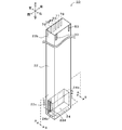
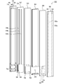
- FIG. 3 is a perspective view of the particle detection element 20.
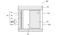
- FIG. 3 is a sectional view taken along line AA of FIG.
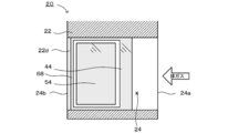
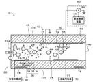
- FIG. 3 is a sectional view taken along line BB of FIG. CC sectional drawing of FIG. 3 is an exploded perspective view of the particle detection element 20.
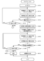
- FIG. 6 is a flowchart showing an example of discharge voltage calibration.
- FIG. 1 is an explanatory view of a particle detector 10 of the present embodiment
- FIG. 2 is a perspective view of a particle detection element 20
- FIG. 3 is a sectional view taken along line AA of FIG. 2
- FIG. 4 is a sectional view taken along line BB of FIG. 5 is a sectional view taken along line CC of FIG. 2
- FIG. 6 is an exploded perspective view of the particle detection element 20.
- the up-down direction, the left-right direction, and the front-back direction are as shown in FIGS. 1 and 2.
- the particle detector 10 detects the number of particles 26 (see FIG. 5) contained in the exhaust gas flowing through the exhaust pipe 12 of the engine.
- the particle detector 10 includes a particle detection element 20 and an accessory unit 80 including various power sources 36 and 56 and a number detection unit 60.
- the fine particle detection element 20 is attached to a ring-shaped pedestal 16 fixed to the exhaust pipe 12 while being inserted into a columnar support 14.
- the particle detection element 20 is protected by the protective cover 18.
- the protective cover 18 is provided with a hole (not shown), and the exhaust gas flowing through the exhaust pipe 12 passes through the gas passage 24 provided at the lower end 22a of the particle detection element 20 through the hole.
- the particle detection element 20 includes a case 22, a charge generation section 30, an excess charge removal section 40, a collection section 50, a guard electrode 68 (see FIGS. 3 and 4 ), And a heater electrode 78.
- the housing 22 is a long rectangular parallelepiped that is long in a direction intersecting the axial direction of the exhaust pipe 12 (here, a direction substantially orthogonal to it).
- the housing 22 is made of ceramic such as alumina.
- the lower end 22 a of the housing 22 is arranged inside the exhaust pipe 12, and the upper end 22 b is arranged outside the exhaust pipe 12.
- a gas flow path 24 is provided at the lower end 22 a of the housing 22.
- Various terminals are provided on the upper end 22b of the housing 22.
- the axial direction of the gas flow path 24 matches the axial direction of the exhaust pipe 12.
- the gas flow path 24 extends from a rectangular gas inlet 24 a provided on the front surface of the housing 22 to a rectangular gas outlet 24 b provided on the rear surface of the housing 22. It is a continuous rectangular parallelepiped space.
- the housing 22 includes a pair of left and right flow path walls 22c and 22d that form a gas flow path 24.
- the charge generation unit 30 is provided on the flow path wall 22c so that charges are generated in the gas flow path 24 in the vicinity of the gas introduction port 24a.
- the charge generator 30 has a discharge electrode 32 and two ground electrodes 34, 34.
- the discharge electrode 32 is provided along the inner surface of the flow path wall 22c, and has a plurality of fine protrusions around a rectangle, as shown in FIG.
- the two ground electrodes 34, 34 are rectangular electrodes, and are embedded in the flow path wall 22c so as to be parallel to the discharge electrode 32 with a space therebetween.
- a pulse voltage of several kV of the discharge power supply 36 (one of the accessory units 80) is applied between the discharge electrode 32 and the two ground electrodes 34, 34.
- an air discharge is generated due to the potential difference between the electrodes.
- the portion of the housing 22 between the discharge electrode 32 and the ground electrodes 34, 34 serves as a dielectric layer.
- the discharge electrode 32 is connected to the discharge electrode terminal 33 (see FIGS. 2 and 6) on the upper end 22b of the housing 22, and is connected to the discharge power supply 36 via this terminal 33.
- the two ground electrodes 34, 34 are connected to a ground electrode terminal 35 (see FIGS. 2 and 6) on the upper end 22b of the housing 22, and are connected to a discharge power supply 36 via this terminal 35.
- the fine particles 26 contained in the gas enter the gas flow path 24 through the gas introduction port 24 a and, when passing through the charge generation unit 30, charge 28 generated by the air discharge of the charge generation unit 30. Is added to form charged fine particles P, and the particles move backward. Further, among the generated charges 28, those not added to the fine particles 26 move backward as the charges 28 as excess charges.
- the surplus charge removal unit 40 is provided downstream of the charge generation unit 30 and upstream of the collection unit 50, as shown in FIGS. 4 and 5.
- the excess charge removing portion 40 has the removing electrode 44, but does not have the applying electrode (the electrode for generating an electric field on the removing electrode 44) at a position facing the removing electrode 44.
- the removal electrode 44 is provided along the inner surface of the flow path wall 22d on the right side and is exposed in the gas flow path 24.
- the removal electrode 44 is connected to the ground via a removal electrode terminal 45 (see FIGS. 2 and 6).
- the collection unit 50 is provided downstream of the charge generation unit 30 and the surplus charge removal unit 40 in the gas flow path 24.
- the collecting unit 50 collects the charged fine particles P, and has a counter electrode (electric field generating electrode) 52 and a collecting electrode 54.
- the counter electrode 52 is provided along the inner surface of the left channel wall 22c and is exposed in the gas channel 24 (see FIGS. 3 and 5).
- the collection electrode 54 is provided along the inner surface of the right channel wall 22d and is exposed in the gas channel 24 (see FIGS. 4 and 5).
- the counter electrode 52 and the collection electrode 54 are arranged at positions facing each other.
- a DC voltage V1 (a positive potential, for example, about 2 kV) is applied to the counter electrode 52 by a collection power supply 56 via a counter electrode terminal 53 (see FIGS. 2 and 6).
- the collection electrode 54 is connected to the ground via the collection electrode terminal 55 (see FIGS. 2 and 6) and the ammeter 64.
- the strength of the electric field generated at the distance, the distance between the removal electrode 44 and the discharge electrode 32, and the distance between the removal electrode 44 and the counter electrode 52 are determined by the collection electrode 54 without the charged fine particles P being collected by the removal electrode 44. It is set so as to be collected and the charge 28 not added to the fine particles 26 is removed by the removal electrode 44.
- the electric mobility of the electric charge 28 is 10 times or more the electric mobility of the charged fine particles P, and the electric field required to collect the electric particles 28 can be reduced by one digit or more. Therefore, such setting can be easily performed. Become.
- the guard electrode 68 is a leakage current absorption electrode that absorbs a leakage current flowing from the counter electrode 52 through the housing 22 to the collection electrode 54.
- the guard electrode 68 is provided on the surface of the flow path wall 22d so as to surround the collection electrode 54 as shown in FIGS. A part of the guard electrode 68 is shared with the removal electrode 44.
- the guard electrode 68 is connected to the ground through the removal electrode terminal 45 (see FIGS. 2 and 6) together with the removal electrode 44. Note that, in FIG. 4, for convenience, the collecting electrode 54 is shown as a quadrangle and the guard electrode 68 is described as having a shape surrounding the quadrangle. Since the lead-out portion is provided, the upper portion of the guard electrode 68 has a shape surrounding the lead-out portion.
- the number detection unit 60 is one of the accessory units 80, and includes an ammeter 64 and a number measurement device 66, as shown in FIG.
- the ammeter 64 has one terminal connected to the collection electrode 54 and the other terminal connected to the ground.
- the ammeter 64 measures the current based on the charge 28 of the charged fine particles P collected by the collecting electrode 54.
- the number measuring device 66 is composed of a microprocessor having a well-known CPU and the like, and calculates the number of the particles 26 based on the current of the ammeter 64.
- the number measuring device 66 corresponds to the arithmetic unit of the present invention.
- the heater electrode 78 is a strip-shaped heating element embedded in the housing 22. Specifically, the heater electrode 78 is returned from one heater electrode terminal 79 of the upper end 22b of the housing 22 to the other heater electrode terminal 79 of the upper end 22b of the housing 22 after being drawn in zigzag. It is wired.
- the heater electrode 78 is connected to a power supply device (not shown) via a pair of heater electrode terminals 79, 79, and generates heat when energized by the power supply device.
- the heater electrode 78 heats each electrode such as the housing 22, the removal electrode 44, and the collection electrode 54.
- the particle detection element 20 is composed of six sheets S1 to S6.
- Each of the sheets S1 to S6 is made of the same material as the case 22.
- the sheets are referred to as a first sheet S1, a second sheet S2,... From left to right, a right side surface of each of the sheets S1 to S6 is referred to as a front surface, and a left side surface is referred to as a back surface.
- the thickness of each of the sheets S1 to S6 may be set appropriately, and may be the same or different, for example.
- a heater electrode 78 is provided on the surface of the first sheet S1. One end and the other end of the heater electrode 78 are arranged above the front surface of the first sheet S1, and the heater electrode terminals 79 are provided above the back surface of the first sheet S1 via the through holes of the first sheet S1. , 79, respectively.
- Ground electrodes 34, 34 are provided on the surface of the second sheet S2.
- the ground electrodes 34, 34 are integrated into one wiring 34a.
- the end of the wiring 34a is arranged above the front surface of the second sheet S2, and is provided above the back surface of the first sheet S1 through the through holes of the second sheet S2 and the first sheet S1. It is connected to the electrode terminal 35.
- the wiring 44a of the removing electrode 44 and the wiring 54a of the collecting electrode 54 are provided along the vertical direction.
- the upper ends of the wirings 44a and 54a are connected to the removal electrode terminals 45 and the collection electrode terminals 55 provided above the back surface of the first sheet S1 through the through holes of the second sheet S2 and the first sheet S1, respectively. ing.
- the discharge electrode 32 and the counter electrode 52 are provided on the surface of the third sheet S3.
- a gas flow path 24, that is, a rectangular parallelepiped space is provided on the lower end side of the fourth sheet S4.
- the removal electrode 44, the collection electrode 54, and the guard electrode 68 are provided on the back surface of the fifth sheet S5.
- the removal electrode 44 integrated with the guard electrode 68 is connected to the wiring 44a of the second sheet S2 through each through hole of the fourth sheet S4 and the third sheet S3, and the removal electrode terminal 45 is connected through this wiring 44a. It is connected to the.
- the collecting electrode 54 is connected to the wiring 54a of the second sheet S2 via the through holes of the fourth sheet S4 and the third sheet S3, and is connected to the collecting electrode terminal 55 via the wiring 54a.
- the wiring 32a of the discharge electrode 32 and the wiring 52a of the counter electrode 52 are provided on the back surface of the sixth sheet S6 along the vertical direction.
- the lower end of the wiring 32a is connected to the discharge electrode 32 provided on the third sheet S3 through the through holes of the fourth to fifth sheets S4 to S5.
- the lower end of the wiring 52a is connected to the counter electrode 52 provided on the third sheet S3 through the through holes of the fourth to fifth sheets S4 to S5.
- the upper ends of the wirings 32a and 52a are respectively connected to the discharge electrode terminal 33 and the counter electrode terminal 53 provided above the surface of the sixth sheet S6 through the through holes of the sixth sheet S6.
- the particle detection element 20 can be manufactured by using a plurality of ceramic green sheets. Specifically, each of the plurality of ceramic green sheets is provided with notches, through holes, or grooves as required, screen-printed with electrodes or wiring patterns, and then laminated and fired. Note that the notches, through holes, and grooves may be filled with a material (for example, an organic material) that will be burned out during firing. Thus, the particle detection element 20 is obtained. Then, the discharge electrode terminal 33 and the counter electrode terminal 53 of the particle detection element 20 are connected to the discharge power supply 36 and the collection power supply 56 of the accessory unit, respectively. Further, the ground electrode terminal 35 and the removal electrode terminal 45 of the particle detection element 20 are connected to the ground. Further, the collecting electrode terminal 55 is connected to the number measuring device 66 via the ammeter 64. Then, the heater electrode terminals 79, 79 are connected to a power supply device (not shown). By doing so, the particle detector 10 can be manufactured.
- a material for example, an organic material
- the fine particle detecting element 20 When measuring the fine particles 26 contained in the exhaust gas of an automobile, the fine particle detecting element 20 is attached to the exhaust pipe 12 of the engine as described above (see FIG. 1). As shown in FIG. 5, the fine particles 26 contained in the exhaust gas introduced into the gas flow path 24 from the gas introduction port 24a are charged with a charge 28 (here, a positive charge) generated by the discharge of the charge generation unit 30. It becomes fine particles P.
- the discharge voltage applied to the discharge electrode 32 of the charge generator 30 is determined by the calibration described below.
- the charged fine particles P have a weak electric field (electric field generated between the removal electrode 44 and the voltage application electrodes (the discharge electrode 32 and the counter electrode 52) arranged around the removal electrode 44), and the length of the removal electrode 44 is long.
- the excess charge removing unit 40 which is shorter than the above, passes through as it is and reaches the collecting unit 50.
- the charges 28 not added to the particles 26 are attracted to the removal electrode 44 of the excess charge removal unit 40 even if the electric field is weak, and are discarded to the ground via the removal electrode 44. As a result, the unnecessary charges 28 that have not been added to the fine particles 26 hardly reach the collection unit 50.
- the charged fine particles P that have reached the collection unit 50 are collected by the collection electrode 54 by the collection electric field generated by the counter electrode 52.
- a current obtained by adding a current based on the noise due to the discharge of the charge generation unit 30 to a current based on the electric charge 28 of the collected charged fine particles P flows through the collection electrode 54.
- the current based on the noise due to the discharge is adjusted to be within an allowable range that does not hinder the detection of the number of particles by performing the calibration described later. Therefore, the current measured by the ammeter 64, that is, the current flowing through the collection electrode 54 can be regarded as a current based on the charge 28 of the charged fine particles P collected by the collection electrode 54.
- the number measuring device 66 calculates the number of the fine particles 26 based on the current (for example, several pA) measured by the ammeter 64.
- the number measuring device 66 integrates (accumulates) the current value over a predetermined period to obtain the integrated value (stored charge amount), divides the stored charge amount by the elementary charge, and obtains the total number of charges (collected charge number).
- the number Nt of the fine particles 26 collected by the collecting electrode 54 is obtained by dividing the number of collected charges by the average value of the number of charges added to one fine particle 26 (average charge number) (see below). (See formula (1)).
- the charged particles P may not be newly collected by the collection electrode 54. Therefore, by heating the collection electrode 54 by the heater electrode 78 periodically or at the timing when the deposition amount reaches a predetermined amount, the deposit on the collection electrode 54 is heated and incinerated, and the collection electrode 54 is heated. Refresh the electrode surface. Further, the heater electrode 78 can also incinerate the fine particles 26 adhering to the inner peripheral surface of the housing 22.
- the guard electrode 68 when detecting the number Nt, the voltage V1 is applied between the counter electrode 52 and the collection electrode 54 of the collection unit 50. Since the voltage V1 is several kV, even in the case 22 made of ceramic such as alumina, which is usually considered to be an electric insulator, a leakage current of several tens to several hundreds pA is generated in the counter electrode 52 and the collection electrode 54. It flows from one side to the other side through the housing 22. On the other hand, the detected current measured by the ammeter 64 when detecting the number Nt is several pA. Therefore, the leakage current affects the detection current.
- such a leakage current is absorbed by the guard electrode 68 and is discarded to the ground.
- the collection electrode 54 is surrounded by the guard electrode 68. Therefore, the influence of the leakage current on the current flowing through the collection electrode 54 can be suppressed.
- This calibration is performed before detecting particulates in the gas.
- This calibration may be performed every time before detecting the particulates in the gas, or may be performed regularly or irregularly instead of every time. Periodically, for example, may be the timing at which the detection of fine particles is performed a predetermined number of times after the previous calibration was performed, or the timing at which a predetermined time has elapsed since the previous calibration was performed.
- the number counting device 66 performs a short-circuit check on the charge generation unit 30, the surplus charge removal unit 40, and the collection unit 50 in advance, and confirms that none of them is short-circuited.
- the number counting device 66 introduces air not containing the particles 26 into the gas flow path 24 (S100) and applies a pulse voltage to the discharge electrode 32 (S110).
- the number measuring device 66 sets the pulse voltage to a relatively low voltage (a voltage that does not cause discharge in the charge generation unit 30, for example, 1.5 kV) when executing S110 for the first time, but when executing the second time or later.
- the pulse voltage is increased stepwise as the number of times increases (step-up application).
- the number measuring device 66 acquires the current flowing through the collection electrode 54 from the ammeter 64 (S120) and determines whether the current is equal to or more than a predetermined threshold value (S130).
- the predetermined threshold value is a current flowing through the collection electrode 54 when the electric charge generation section 30 starts discharging, and can be empirically obtained by experiments or the like. If the current flowing through the collection electrode 54 is less than the predetermined threshold value in S130, the counting device 66 determines whether or not the current pulse voltage has reached the upper limit value (S135), and has to reach the upper limit value. For example, after returning to S110 and applying a pulse voltage that is one step higher than the previous time to the discharge electrode 32, the processing from S120 is executed again.
- the number measuring device 66 sets the pulse voltage at that time to the initial voltage (discharge). (Start voltage) (S140).
- the number measuring device 66 applies a predetermined DC voltage to the counter electrode 52 (S150).
- a predetermined DC voltage is set so that such a blocking electric field is generated.
- an electric field is generated between the counter electrode 52 and the collection electrode 54, but the charged particles P move along with the flow of gas, so that the counter electrode 52 is not pushed back to the upstream side. And the collection electrode 54.
- the number measuring device 66 applies a pulse voltage to the discharge electrode 32 (S160).
- the number measuring device 66 sets the pulse voltage to the initial voltage when executing S160 for the first time, but increases the pulse voltage stepwise as the number of times increases when executing the second and subsequent times (step-up). Applied). Subsequently, the number measuring device 66 acquires the current flowing through the collecting electrode 54 from the ammeter 64 (S170), obtains the average current flowing within a fixed time, and determines whether the average current is within the allowable range. (S180).
- the current flowing through the collection electrode 54 is noise in the collection electrode 54 and is caused by the discharge of the charge generation unit 30, that is, discharge noise (fine particles 26 because there are no fine particles in the gas flow path 24).
- the charge 28 generated in the charge generation unit 30 is also blocked so as not to enter between the counter electrode 52 and the collection electrode 54, and thus is not caused by the charge 28).
- the waveform of the current flowing through the collection electrode 54 has an irregular sawtooth waveform (for example, one peak appears every several hundred msec). Therefore, the average current is obtained, and it is determined whether the average current is within the allowable range.
- the permissible range is set to a range (for example, the comma number pA) in which the discharge noise in the collection electrode 54 does not affect the detection of the number of fine particles.
- the allowable range can be obtained by conducting a preliminary experiment or the like.
- the number counting device 66 determines whether or not the current pulse voltage has reached the upper limit value (S190), and if it has not reached the upper limit value, returns to S160. Then, a pulse voltage that is one step higher than the previous time is applied to the discharge electrode 32, and then the processing from S170 is executed again. On the other hand, if the average current exceeds the allowable range in S180, the number measuring device 66 discharges the pulse voltage set immediately before (that is, the maximum or almost maximum pulse voltage within which the average current falls within the allowable range). The voltage is determined and stored in a memory (not shown) (S210), and the calibration is completed.
- the discharge voltage stored in the memory is used as the voltage applied to the discharge electrode 32 until the next calibration is executed and updated. If the discharge voltage determined in this way is applied to the discharge electrode 32, a sufficient amount of electric charge that exceeds the minimum amount necessary for detecting fine particles is generated in the electric charge generation unit 30, and noise due to the generation of electric charge is eliminated. It can be suppressed to the extent that it does not affect the detection of fine particles.
- the number measuring device 66 issues a warning (S200) and ends the calibration.
- the pulse voltage is positively determined in S130 or negatively determined in S180 before reaching the upper limit value.
- the pulse voltage exceeds the upper limit value, there is a possibility that some abnormality has occurred. Because it is expensive, I try to issue a warning.
- the discharge voltage of the generator 30 is determined.
- the electric charge is generated by the electric discharge in the electric charge generating section 30, but since the surrounding environment (for example, temperature, humidity, the adhesion state of the fine particles in the gas flow path, etc.) affects the electric discharge and the generation of the electric charges, the fine particles in the gas are discharged.
- the discharge voltage is determined. By doing so, it is possible to suppress the influence of noise caused by the discharge of the charge generation unit 30 on the detection of fine particles, and it is possible to improve the detection accuracy of fine particles.
- the number measuring device 66 prevents fine particles from entering the gas flow path 24 and generates a blocking electric field between the counter electrode 52 and the collection electrode 54.
- the noise in the collection electrode 54 is measured as an average current while increasing the pulse voltage applied to the charge generation unit 30 from the initial voltage, and the average current is set within the allowable range.
- the noise in the collection electrode 54 does not include noise caused by the particles adhering to the collection electrode 54 or noise caused by the charges generated in the charge generation unit 30 adhering to the collection electrode 54. Therefore, it can be substantially regarded as noise caused by the discharge of the charge generation unit 30. Therefore, the discharge voltage can be determined so that the noise caused by the discharge of the charge generation unit 30 falls within the allowable range.
- the number measuring device 66 determines the voltage applied to the charge generation unit 30 immediately before the noise exceeds the allowable range as the discharge voltage. As a result, the maximum or almost maximum applied voltage at which noise falls within the permissible range is determined as the discharge voltage, so that a sufficient amount of charge can be generated while suppressing noise when detecting particles.
- the collection target is the charged fine particles P
- the error is easier to be smaller than the case where the charge (excess charge) not added to the fine particles is set as the collection target, so that the measurement accuracy is improved.
- the leak current is absorbed by the guard electrode 68, the leak current is prevented from being added to the current flowing through the collecting electrode 54. Therefore, it is possible to prevent the detection accuracy from being lowered due to the influence of the leakage current, and it is possible to improve the detection accuracy of the number of fine particles.
- guard electrode 68 is shared with the removal electrode 44, the structure of the electrode can be simplified.
- the removal electrode 44 does not have its own power source for generating an electric field on the removal electrode 44, and the removal electrode 44 and the voltage application electrodes (the discharge electrode 32 and the counter electrode 52) arranged around the removal electrode 44 are not provided.
- the excess electric charge 28 is removed to the ground by utilizing the electric field generated between them. Therefore, the configuration of the particle detector 10 can be simplified as compared with the case where the removal electrode 44 has its own power source for generating an electric field.
- the number of fine particles is calculated with the collection target as the charged fine particles P, but the number of particles may be calculated with the collection target as excess charges.
- the removal electrode 44 and the guard electrode 68 are omitted, the voltage applied by the collection power source 56 to the counter electrode 52 is set lower than the voltage V1, and the excess charge is collected in the collection electrode 54.
- the charged fine particles P may be collected and discharged from the gas discharge port 24b without being collected by the collection electrode 54.
- the total number of the electric charges 28 generated in the electric charge generating unit 30 is measured, and thereafter, when the gas containing the fine particles 26 is flown in the gas flow path 24, the excess electric charge is generated from the current flowing in the collecting electrode 54.
- the number of fine particles is determined by measuring the number and subtracting the number of surplus charges from the total number of charges 28. Even in this case, if the same calibration as in FIG. 7 is executed, it is possible to suppress the influence of the noise caused by the discharge of the charge generation unit 30 on the detection of the particles, and it is possible to improve the detection accuracy of the particles. it can. However, in this case, it is necessary to measure both the total number of charges 28 and the number of surplus charges, and the charge 28 is lighter than the fine particles 26 and has unstable behavior. Considering that it is several orders of magnitude smaller than the above, it is possible to reduce the error by using the charged fine particles P as the collection target.
- the voltage (minimum detection voltage) for generating the minimum amount of electric charges required for detection of fine particles is generally known by preliminary experiments, S110 It is also possible to omit S135 to S135 and use the detected minimum voltage instead of the discharge start voltage as the initial voltage in S140. Even in this case, it is possible to suppress the influence of the noise caused by the discharge of the charge generation unit 30 on the detection of the fine particles, and it is possible to improve the detection accuracy of the fine particles.
- the discharge start voltage is about 1.5 to 1.6 kV and the minimum detection voltage is about 1.7 kV, although it varies depending on the surrounding environment.
- both electrodes 68 and 44 may be connected to the ground via a common wire, or may be connected to the ground via individual wires.
- the guard electrode 68 is provided in the above-described embodiment, the guard electrode 68 may be omitted if the housing 22 has a high electric insulation property and the leakage current is substantially zero without the guard electrode 68. ..
- the surplus charge removing unit 40 is described as having no application electrode for generating an electric field on the removal electrode 44 or an original removal power source for applying a voltage to the application electrode.
- an applying electrode may be provided at a position (left wall 22c on the left side) facing the removing electrode 44, and a removing power source for applying a voltage to the applying electrode may be provided.
- the voltage applied to the removal electrode 44 is adjusted so as to collect the excess charges 28 but not the charged fine particles P.
- the charge generation unit 30 is provided on the left channel wall 22c of the housing 22, but instead of or in addition to this, the right channel wall 22d may be provided with the charge generation unit.
- the counter electrode 52 is exposed to the gas flow path 24, but it is not limited to this and may be embedded in the housing 22.
- the particulate matter detector 10 is attached to the exhaust pipe 12 of the engine, but the particulate matter detector 10 is not particularly limited to the exhaust pipe 12 of the engine, and may be any pipe as long as a gas containing particulates flows. Such a tube may be used.
- the particle detection element 20 detects the number of particles, but it may detect the mass or surface area of the particles.
- the mass of the fine particles can be obtained, for example, by multiplying the number of the fine particles by the average mass of the fine particles, and the relationship between the accumulated charge amount and the mass of the collected fine particles is stored in a storage device as a map in advance. It is also possible to obtain the mass of the fine particles from the accumulated charge amount using this map.
- the surface area of the fine particles can also be obtained by the same method as the mass of the fine particles.
- the present invention can be used for a particle detector that detects particles contained in a gas.
Landscapes
- Chemical & Material Sciences (AREA)
- Analytical Chemistry (AREA)
- Physics & Mathematics (AREA)
- Health & Medical Sciences (AREA)
- Life Sciences & Earth Sciences (AREA)
- Biochemistry (AREA)
- General Health & Medical Sciences (AREA)
- General Physics & Mathematics (AREA)
- Immunology (AREA)
- Pathology (AREA)
- Electrochemistry (AREA)
- Chemical Kinetics & Catalysis (AREA)
- Dispersion Chemistry (AREA)
- Other Investigation Or Analysis Of Materials By Electrical Means (AREA)
Abstract
微粒子検出器10は、ガス流路24を有する筐体22と、ガス中の微粒子26に放電によって発生させた電荷28を付加して帯電微粒子Pにする電荷発生部30と、帯電微粒子Pを捕集する捕集電極54と、捕集電極54に向けて帯電微粒子Pを移動させる捕集用電界を発生させる対向電極52と、捕集電極54に捕集された帯電微粒子Pに応じて変化する物理量に基づいて微粒子数を検出する個数測定装置66とを備える。個数測定装置66は、微粒子数を検出する前に、捕集電極54における放電ノイズが予め定められた許容範囲内に収まるよう微粒子を検出する際の電荷発生部30の放電電圧を決定する。
Description
本発明は、微粒子検出器に関する。
微粒子検出器としては、ガス流路を有するセラミック製の筐体と、ガス流路内に導入されたガス中の微粒子に放電によって発生させた電荷を付加して帯電微粒子にする電荷発生部と、ガス流路内で電荷発生部よりも下流側で帯電微粒子を捕集する捕集部と、捕集された帯電微粒子の電荷の量に基づいて微粒子の個数を測定する個数測定部とを備えたものが知られている(例えば特許文献1参照)。捕集部は、ガス流路に露出している捕集電極と、ガス流路を挟んで捕集電極に対向している対向電極とを有している。捕集電極は、捕集電極と対向電極との間に印加された電圧によってガス流路のうち捕集電極と対向電極との間に発生した電界を利用して、帯電微粒子を捕集する。捕集された帯電微粒子の電荷の量は、微小な電流(例えば数pA)として検出される。
しかしながら、捕集された帯電微粒子の電荷の量は微小な電流(例えば数pA)として検出されるため、捕集電極の周囲のノイズの影響を受けやすく、精度よく検出するのが難しかった。
本発明はこのような課題を解決するためになされたものであり、微粒子の検出精度を高めることを主目的とする。
本発明の微粒子検出器は、
ガス中の微粒子を検出するために用いられる微粒子検出器であって、
前記ガスが通過するガス流路を有する筐体と、
前記ガス流路内に導入された前記ガス中の微粒子に放電によって発生させた電荷を付加して帯電微粒子にする電荷発生部と、
前記帯電微粒子と前記微粒子に付加されなかった前記電荷とのいずれかである捕集対象を捕集する捕集電極と、
前記捕集電極に対向する位置に設けられ、前記捕集電極に向けて前記捕集対象を移動させる捕集用電界を発生させる電界発生電極と、
前記捕集電極に捕集された前記捕集対象に応じて変化する物理量に基づいて前記微粒子を検出する演算部と、
を備え、
前記演算部は、前記物理量に基づいて前記微粒子を検出する前に、前記捕集電極における放電ノイズが予め定められた許容範囲内に収まるよう前記微粒子を検出する際の前記電荷発生部の放電電圧を決定する、
ものである。
この微粒子検出器では、電荷発生部が電荷を発生させることでガス中の微粒子を帯電微粒子にし、捕集用電界によって捕集電極に向けて捕集対象(帯電微粒子と微粒子に付加されなかった電荷とのいずれか)を移動させて捕集電極で捕集する。演算部は、捕集電極に捕集された捕集対象に応じて変化する物理量に基づいてガス中の微粒子を検出する。また、演算部は、ガス中の微粒子を検出する前に、捕集電極における放電ノイズが予め定められた許容範囲内に収まるよう微粒子を検出する際の電荷発生部の放電電圧を決定する。電荷発生部では放電によって電荷が発生するが、周囲の環境(例えば温度、湿度、ガス流路内への微粒子の付着状況など)が放電や電荷の発生に影響を及ぼすため、ガス中の微粒子を検出する前に放電電圧を決定する。放電ノイズは、捕集電極におけるノイズであって電荷発生部の放電に起因するものをいう。放電ノイズの許容範囲は、放電ノイズが演算部による微粒子の検出に影響を与えないように設定される。こうすることにより、電荷発生部の放電に起因するノイズが微粒子検出へ与える影響を抑制することができ、ひいては微粒子の検出精度を高めることができる。
演算部は、毎回ガス中の微粒子を検出する前に電荷発生部の放電電圧を決定してもよいし、定期的に又は不定期にガス中の微粒子を検出する前に電荷発生部の放電電圧を決定してもよい。
なお、本明細書において、「電荷」とは、正電荷や負電荷のほかイオンを含むものとする。「物理量」とは、捕集対象の数(電荷量)に基づいて変化するパラメータであればよく、例えば電流などが挙げられる。演算部は、物理量に基づいて微粒子の量を検出してもよく、その場合、微粒子の量は、例えば微粒子の数,質量,表面積の少なくともいずれかであってもよい。「微粒子の量を検出する」とは、微粒子の量を測定する場合のほか、微粒子の量が所定の数値範囲に入るか否か(例えば所定のしきい値を超えるか否か)を判定する場合も含むものとする。
本発明の微粒子検出器において、前記演算部は、前記放電電圧を決定するにあたり、前記微粒子の検出に最低限必要な量を超える量の電荷が前記電荷発生部で発生するよう前記放電電圧を決定してもよい。微粒子の検出に最低限必要な量の電荷は、例えば微粒子検出の予備実験などを行うことにより決定することができる。
本発明の微粒子検出器において、前記演算部は、前記放電電圧を決定するにあたり、前記ガス流路に微粒子が入らないようにすると共に、前記電界発生電極に所定の電圧を印加することにより前記電界発生電極と前記捕集電極との間へ前記電荷発生部で発生した電荷が入らないような遮断用電界を前記電界発生電極と前記捕集電極との間に発生させた状態で、前記電荷発生部に印加する電圧を初期電圧から上昇させながら前記捕集電極におけるノイズを測定し、前記ノイズが前記許容範囲内に収まるよう前記放電電圧を決定してもよい。この場合、捕集電極におけるノイズは、微粒子が捕集電極に付着するのに起因するノイズや電荷発生部で発生した電荷が捕集電極に付着するのに起因するノイズを含まないため、実質的に、電荷発生部の放電に起因するノイズとみなすことができる。そのため、電荷発生部の放電に起因するノイズが許容範囲内に収まるよう放電電圧を決定することができる。
この際、前記演算部は、前記ノイズが前記許容範囲を超える直前に前記電荷発生部に印加した電圧を前記放電電圧に決定してもよい。この場合、電荷発生部に印加する電圧を初期電圧から上昇させていき、ノイズが許容範囲を超える直前に電荷発生部に印加した電圧に放電電圧を決定する。こうすれば、ノイズが許容範囲内に収まる最大又はほぼ最大の印加電圧が放電電圧に決定されるため、微粒子を検出する際にはノイズを抑制しつつ十分な量の電荷を発生させることができる。
また、前記演算部は、前記初期電圧を設定するにあたり、前記ガス流路に微粒子が入らないようにすると共に前記電界発生電極に電圧を印加しない状態で、前記電荷発生部の印加電圧を上昇させながら前記電荷発生部で発生した電荷に応じて変化する前記捕集電極の物理量を測定し、前記物理量が規定値以上又は前記規定値を超えたときの前記電荷発生部に印加した電圧を前記初期電圧に設定してもよい。こうすれば、電荷発生部で電荷が発生し始めたときの印加電圧つまり放電開始電圧を初期電圧に設定することができる。
本発明の微粒子検出器において、前記捕集対象は、前記帯電微粒子であってもよい。微粒子に付加されなかった電荷を捕集対象にする場合に比べて、帯電微粒子を捕集対象にする場合には、誤差を小さくしやすいため測定精度が高くなる。
捕集対象を帯電微粒子とする本発明の微粒子検出器は、前記電荷発生部と前記捕集電極との間に設けられ、前記電荷発生部で発生した電荷のうち前記微粒子に付加しなかった余剰電荷を捕集して除去する余剰電荷除去電極を備えていてもよい。こうすれば、電界発生電極と捕集電極との間に遮断用電界を発生させた場合、遮断用電界によって捕集電極の上流側に押し返された電荷は余剰電荷除去電極によって除去される。
本発明の好適な実施形態について、図面を用いて説明する。図1は本実施形態の微粒子検出器10の説明図、図2は微粒子検出素子20の斜視図、図3は図2のA-A断面図、図4は図2のB-B断面図、図5は図2のC-C断面図、図6は微粒子検出素子20の分解斜視図である。なお、本実施形態において、上下方向,左右方向及び前後方向は、図1~図2に示した通りとする。
微粒子検出器10は、図1に示すように、エンジンの排気管12を流れる排ガスに含まれる微粒子26(図5参照)の数を検出するものである。この微粒子検出器10は、微粒子検出素子20と、各種電源36,56や個数検出部60を含む付属ユニット80とを備えている。
微粒子検出素子20は、図1に示すように、円柱状の支持体14に差し込まれた状態で、排気管12に固定されたリング状の台座16に取り付けられている。微粒子検出素子20は、保護カバー18によって保護されている。保護カバー18には図示しない穴が設けられており、この穴を介して排気管12を流通する排ガスが微粒子検出素子20の下端22aに設けられたガス流路24を通過する。微粒子検出素子20は、図5に示すように、筐体22に、電荷発生部30と、余剰電荷除去部40と、捕集部50と、ガード電極68(図3及び図4参照)と、ヒータ電極78とを備えたものである。
筐体22は、図1に示すように、排気管12の軸方向と交差する方向(ここでは略直交する方向)に長い長尺の直方体である。筐体22は、例えばアルミナなどのセラミック製である。筐体22の下端22aは排気管12の内部に配置され、上端22bは排気管12の外部に配置される。筐体22の下端22aには、ガス流路24が設けられている。筐体22の上端22bには、各種端子が設けられている。
ガス流路24の軸方向は、排気管12の軸方向と一致している。ガス流路24は、図2に示すように、筐体22の前方の面に設けられた矩形のガス導入口24aから、筐体22の後方の面に設けられた矩形のガス排出口24bまで連なる直方体形状の空間である。筐体22は、ガス流路24を構成する左右一対の流路壁22c,22dを備えている。
電荷発生部30は、図3及び図5に示すように、ガス流路24内のガス導入口24aの近傍に電荷が発生するように、流路壁22cに設けられている。電荷発生部30は、放電電極32と2つのグランド電極34,34とを有している。放電電極32は、流路壁22cの内面に沿って設けられ、図3に示すように、矩形の周囲に複数の微細突起を有している。2つのグランド電極34,34は、矩形電極であり、流路壁22cに間隔をあけて放電電極32と平行となるように埋設されている。電荷発生部30では、図5に示すように、放電電極32と2つのグランド電極34,34との間に放電用電源36(付属ユニット80の1つ)の数kVのパルス電圧が印加されることで、両電極間の電位差による気中放電が発生する。このとき、筐体22のうち放電電極32とグランド電極34,34との間の部分が誘電体層の役割を果たす。この気中放電によって、放電電極32の周囲に存在するガスがイオン化されて正の電荷28が発生する。放電電極32は、筐体22の上端22bの放電電極端子33(図2及び図6参照)に接続され、この端子33を介して放電用電源36に接続されている。また、2つのグランド電極34,34は、筐体22の上端22bのグランド電極端子35(図2及び図6参照)に接続され、この端子35を介して放電用電源36に接続されている。
ガスに含まれる微粒子26は、図5に示すように、ガス導入口24aからガス流路24内に入り、電荷発生部30を通過する際に電荷発生部30の気中放電によって発生した電荷28が付加されて帯電微粒子Pとなったあと後方に移動する。また、発生した電荷28のうち微粒子26に付加されなかったものは、余剰電荷として電荷28のまま後方に移動する。
余剰電荷除去部40は、図4及び図5に示すように、電荷発生部30の下流で且つ捕集部50の上流に設けられている。余剰電荷除去部40は、除去電極44を有しているが、除去電極44に対向する位置に印加電極(除去電極44上に電界を発生させるための電極)を有していない。除去電極44は、右側の流路壁22dの内面に沿って設けられ、ガス流路24内に露出している。除去電極44は、除去電極端子45(図2及び図6参照)を介してグランドに接続されている。
捕集部50は、図5に示すように、ガス流路24のうち電荷発生部30及び余剰電荷除去部40よりも下流に設けられている。捕集部50は、帯電微粒子Pを捕集するものであり、対向電極(電界発生電極)52と捕集電極54とを有している。対向電極52は、左側の流路壁22cの内面に沿って設けられ、ガス流路24内に露出している(図3及び図5参照)。捕集電極54は、右側の流路壁22dの内面に沿って設けられ、ガス流路24内に露出している(図4及び図5参照)。対向電極52と捕集電極54とは互いに向かい合う位置に配設されている。対向電極52は、対向電極端子53(図2及び図6参照)を介して直流電圧V1(正電位、例えば2kV程度)が捕集用電源56によって印加される。捕集電極54は、捕集電極端子55(図2及び図6参照)を介して電流計64を経てグランドに接続されている。これにより、捕集部50の対向電極52と捕集電極54との間には、帯電微粒子Pを捕集電極54に向けて移動させる比較的強い電界が発生する。したがって、ガス流路24を流れる帯電微粒子Pは、この比較的強い電界によって捕集電極54に引き寄せられて捕集される。
なお、余剰電荷除去部40の除去電極44のサイズ、放電電極32と除去電極44との間の電界の強さ、捕集部50の各電極52,54のサイズ、両電極52,54の間に発生させる電界の強さ、除去電極44と放電電極32との距離、除去電極44と対向電極52との距離は、帯電微粒子Pが除去電極44に捕集されることなく捕集電極54に捕集されるように、また、微粒子26に付加しなかった電荷28が除去電極44によって除去されるように、設定されている。一般に、電荷28の電気移動度は、帯電微粒子Pの電気移動度の10倍以上であり、捕集するのに必要な電界は1桁以上小さくて済むので、このような設定が容易に可能となる。
ガード電極68は、対向電極52から筐体22を経て捕集電極54へ流れる漏れ電流を吸収する漏れ電流吸収電極である。ガード電極68は、図4及び図5に示すように捕集電極54を囲むように流路壁22dの表面に設けられている。ガード電極68の一部は除去電極44と共通化されている。ガード電極68は、除去電極44と共に除去電極端子45(図2及び図6参照)を介してグランドに接続されている。なお、図4では、便宜上、捕集電極54を四角形で表しガード電極68はその四角形を囲う形状として記載したが、実際には、捕集電極54の上部には図6に示すように端子接続用の引き出し部が設けられているため、ガード電極68の上部はこの引き出し部も囲う形状となっている。
個数検出部60は、付属ユニット80の1つであり、図5に示すように、電流計64と個数測定装置66とを備えている。電流計64は、一方の端子が捕集電極54に接続され、もう一方の端子がグランドに接続されている。この電流計64は、捕集電極54に捕集された帯電微粒子Pの電荷28に基づく電流を測定する。個数測定装置66は、周知のCPUなどを備えたマイクロプロセッサからなり、電流計64の電流に基づいて微粒子26の個数を演算する。個数測定装置66は、本発明の演算部に相当する。
ヒータ電極78は、筐体22に埋設された帯状の発熱体である。具体的には、ヒータ電極78は、筐体22の上端22bの一方のヒータ電極端子79から、ジグザグに引き回されたあと、筐体22の上端22bの他方のヒータ電極端子79に戻るように配線されている。ヒータ電極78は、一対のヒータ電極端子79,79を介して図示しない給電装置に接続され、その給電装置によって通電されると発熱する。ヒータ電極78は、筐体22や除去電極44,捕集電極54などの各電極を加熱する。
ここで、微粒子検出素子20の構成について、図6の分解斜視図を用いて更に説明する。微粒子検出素子20は、6枚のシートS1~S6で構成されている。各シートS1~S6は、筐体22と同じ材料で形成されている。説明の便宜上、左から右に向かって第1シートS1、第2シートS2、…と称し、各シートS1~S6における右側の面を表面、左側の面を裏面と称する。各シートS1~S6の厚みは適宜設定すればよく、例えばすべて同じであってもよいし、それぞれ異なっていてもよい。
第1シートS1の表面には、ヒータ電極78が設けられている。ヒータ電極78の一端及び他端は、第1シートS1の表面の上方に配置されており、第1シートS1のスルーホールを介して第1シートS1の裏面の上方に設けられたヒータ電極端子79,79にそれぞれ接続されている。
第2シートS2の表面には、グランド電極34,34が設けられている。グランド電極34,34は1本の配線34aにまとめられている。その配線34aの端部は、第2シートS2の表面の上方に配置されており、第2シートS2及び第1シートS1のスルーホールを介して第1シートS1の裏面の上方に設けられたグランド電極端子35に接続されている。第2シートS2の表面には、除去電極44の配線44aと捕集電極54の配線54aが上下方向に沿ってそれぞれ設けられている。各配線44a,54aの上端は、第2シートS2及び第1シートS1のスルーホールを介して第1シートS1の裏面の上方に設けられた除去電極端子45及び捕集電極端子55にそれぞれ接続されている。
第3シートS3の表面には、放電電極32及び対向電極52が設けられている。
第4シートS4の下端側には、ガス流路24すなわち直方体形状の空間が設けられている。
第5シートS5の裏面には、除去電極44、捕集電極54及びガード電極68が設けられている。ガード電極68と一体化された除去電極44は、第4シートS4及び第3シートS3の各スルーホールを介して第2シートS2の配線44aに接続され、この配線44aを介して除去電極端子45に接続されている。捕集電極54は、第4シートS4及び第3シートS3の各スルーホールを介して第2シートS2の配線54aに接続され、この配線54aを介して捕集電極端子55に接続されている。
第6シートS6の裏面には、放電電極32の配線32aと対向電極52の配線52aとが上下方向に沿ってそれぞれ設けられている。配線32aの下端は、第4~第5シートS4~S5の各スルーホールを介して第3シートS3に設けられた放電電極32に接続されている。配線52aの下端は、第4~第5シートS4~S5の各スルーホールを介して第3シートS3に設けられた対向電極52に接続されている。各配線32a,52aの上端は、第6シートS6のスルーホールを介して第6シートS6の表面の上方に設けられた放電電極端子33及び対向電極端子53にそれぞれ接続されている。
次に、微粒子検出器10の製造例について説明する。微粒子検出素子20は、複数枚のセラミックグリーンシートを用いて作製することができる。具体的には、複数枚のセラミックグリーンシートの各々について、必要に応じて切欠や貫通孔や溝を設けたり電極や配線パターンをスクリーン印刷したりした後、それらを積層して焼成する。なお、切欠や貫通孔や溝については、焼成時に焼失するような材料(例えば有機材料)で充填しておいてもよい。こうして、微粒子検出素子20を得る。続いて、微粒子検出素子20の放電電極端子33及び対向電極端子53をそれぞれ付属ユニットの放電用電源36及び捕集用電源56に接続する。また、微粒子検出素子20のグランド電極端子35及び除去電極端子45をグランドに接続する。更に、捕集電極端子55を電流計64を介して個数測定装置66に接続する。そして、ヒータ電極端子79,79を図示しない給電装置に接続する。こうすることにより、微粒子検出器10を製造することができる。
次に、微粒子検出器10の使用例について説明する。自動車の排ガスに含まれる微粒子26を計測する場合、上述したようにエンジンの排気管12に微粒子検出素子20を取り付ける(図1参照)。図5に示すように、ガス導入口24aからガス流路24内に導入された排ガスに含まれる微粒子26は、電荷発生部30の放電によって発生した電荷28(ここでは正電荷)を帯びて帯電微粒子Pになる。電荷発生部30の放電電極32に印加される放電電圧は、後述するキャリブレーションによって決定される。帯電微粒子Pは、電界(除去電極44とその周囲に配置された電圧印加電極(放電電極32や対向電極52)との間に発生する電界)が弱く除去電極44の長さが捕集電極54よりも短い余剰電荷除去部40をそのまま通過して、捕集部50に至る。一方、微粒子26に付加されなかった電荷28は、電界が弱くても余剰電荷除去部40の除去電極44に引き寄せられ、除去電極44を介してグランドに捨てられる。これにより、微粒子26に付加されなかった不要な電荷28は捕集部50にほとんど到達することがない。
捕集部50に到達した帯電微粒子Pは、対向電極52によって発生した捕集用電界によって捕集電極54に捕集される。捕集電極54には、捕集された帯電微粒子Pの電荷28に基づく電流に、電荷発生部30の放電によるノイズに基づく電流が加算された電流が流れる。放電によるノイズに基づく電流は、後述するキャリブレーションを行うことによって、微粒子数の検出の妨げにならない許容範囲に収まるように調整されている。そのため、電流計64で測定された電流すなわち捕集電極54に流れる電流は、捕集電極54に捕集された帯電微粒子Pの電荷28に基づく電流とみなすことができる。個数測定装置66は、電流計64で測定された電流(例えば数pA)に基づいて微粒子26の個数を演算する。電流Iと電荷量qの関係は、I=dq/(dt)、q=∫Idtである。個数測定装置66は、所定期間にわたって電流値を積分(累算)してその積分値(蓄積電荷量)を求め、蓄積電荷量を素電荷で除算して電荷の総数(捕集電荷数)を求め、その捕集電荷数を1つの微粒子26に付加する電荷の数の平均値(平均帯電数)で除算することで、捕集電極54に捕集された微粒子26の個数Ntを求める(下記式(1)参照)。個数測定装置66は、この個数Ntを排ガス中の微粒子26の数として検出する。
Nt=(蓄積電荷量)/{(素電荷)×(平均帯電数)} …(1)
Nt=(蓄積電荷量)/{(素電荷)×(平均帯電数)} …(1)
微粒子検出素子20の使用に伴い、微粒子26等が捕集電極54に数多く堆積すると、新たに帯電微粒子Pが捕集電極54に捕集されないことがある。そのため、定期的にあるいは堆積量が所定量に達したタイミングで、捕集電極54をヒータ電極78によって加熱することにより、捕集電極54上の堆積物を加熱して焼却し捕集電極54の電極面をリフレッシュする。また、ヒータ電極78により、筐体22の内周面に付着した微粒子26を焼却することもできる。
次に、ガード電極68の役割について説明する。微粒子検出器10では、個数Ntを検出する際に、捕集部50の対向電極52と捕集電極54との間に電圧V1を印加する。電圧V1は数kVであるため、通常は電気絶縁体と考えられているアルミナ等のセラミックからなる筐体22であっても数10~数100pAの漏れ電流が対向電極52及び捕集電極54の一方から筐体22を経て他方へ流れる。一方、個数Ntを検出する際に電流計64で測定される検出電流は数pAである。そのため、漏れ電流は検出電流に影響を与える。本実施形態では、こうした漏れ電流をガード電極68が吸収してグランドに捨てる。捕集電極54はガード電極68によって囲まれている。そのため、捕集電極54に流れる電流に漏れ電流が影響するのを抑制することができる。
次に、個数測定装置66によって実行される放電電圧のキャリブレーションについて説明する。このキャリブレーションは、ガス中の微粒子を検出する前に実行される。このキャリブレーションは、ガス中の微粒子を検出する前に毎回実行してもよいし、毎回ではなく定期的に又は不定期に実行してもよい。定期的とは、例えば、前回キャリブレーションを実行してから微粒子の検出を所定回数実行したタイミングとしてもよいし、前回キャリブレーションを実行してから所定時間が経過したタイミングとしてもよい。
キャリブレーションの一例を図7のフローチャートに基づいて以下に説明する。個数測定装置66は、キャリブレーションの開始前に、予め電荷発生部30、余剰電荷除去部40及び捕集部50の短絡点検を行い、それらのいずれにおいても短絡していないことを確認する。
個数測定装置66は、キャリブレーションを開始すると、微粒子26を含まないエアをガス流路24に導入し(S100)、放電電極32にパルス電圧を印加する(S110)。個数測定装置66は、初めてS110を実行する際には、パルス電圧を比較的低い電圧(電荷発生部30で放電が起きない電圧、例えば1.5kV)に設定するが、2回目以降実行する際には回を重ねるにしたがってパルス電圧を段階的に上げていく(ステップアップ印加)。続いて、個数測定装置66は、捕集電極54を流れる電流を電流計64から取得し(S120)、その電流が所定の閾値以上か否かを判定する(S130)。所定の閾値は、電荷発生部30で放電が開始したときに捕集電極54を流れる電流であり、実験などにより経験的に求めることができる。S130で捕集電極54を流れる電流が所定の閾値未満だったならば、個数測定装置66は現在のパルス電圧が上限値に達しているか否かを判定し(S135)、上限値に達していなければ、S110に戻って前回よりも一段高いパルス電圧を放電電極32に印加したあと、再びS120以降の処理を実行する。一方、S130で捕集電極54を流れる電流が所定の閾値以上だったならば、すなわち電荷発生部30で放電が起きたならば、個数測定装置66は、そのときのパルス電圧を初期電圧(放電開始電圧)に決定する(S140)。
続いて、個数測定装置66は、対向電極52に所定の直流電圧を印加する(S150)。これにより、対向電極52と捕集電極54との間には、対向電極52と捕集電極54との間へ電荷発生部30で発生した電荷28が電気的反発により入らないような遮断用電界が発生する。所定の直流電圧は、このような遮断用電界が発生するように設定されている。ちなみに、微粒子数検出時にも、対向電極52と捕集電極54との間に電界を発生させるが、帯電微粒子Pはガスの流れに乗って移動するため、上流側に押し戻されることなく対向電極52と捕集電極54との間に入り込む。続いて、個数測定装置66は、放電電極32にパルス電圧を印加する(S160)。個数測定装置66は、初めてS160を実行する際には、パルス電圧を初期電圧に設定するが、2回目以降実行する際には回を重ねるにしたがってパルス電圧を段階的に上げていく(ステップアップ印加)。続いて、個数測定装置66は、捕集電極54に流れる電流を電流計64から取得し(S170)、一定時間内に流れる平均電流を求め、その平均電流が許容範囲内か否かを判定する(S180)。
捕集電極54に流れる電流は、捕集電極54におけるノイズであって電荷発生部30の放電に起因するもの、すなわち放電ノイズである(ガス流路24内に微粒子が存在していないため微粒子26に起因するものではなく、電荷発生部30で発生した電荷28も対向電極52と捕集電極54との間に入らないように遮断されているため電荷28に起因するものでもない)。捕集電極54に流れる電流の波形は、不定期なノコギリ波状(例えば数百msecに1つのピークが現れる)である。そのため、平均電流を求めて、その平均電流が許容範囲内か否かを判定する。許容範囲は、捕集電極54における放電ノイズが微粒子数の検出に影響を与えない範囲(例えばコンマ数pA)に設定されている。許容範囲は、予備実験を行うこと等により求めることができる。
S180で平均電流が許容範囲内だったならば、個数測定装置66は、現在のパルス電圧が上限値に達しているか否かを判定し(S190)、上限値に達していなければ、S160に戻って前回よりも一段高いパルス電圧を放電電極32に印加したあと、再びS170以降の処理を実行する。一方、S180で平均電流が許容範囲を超えていたならば、個数測定装置66は、一つ前に設定したパルス電圧(つまり平均電流が許容範囲内に収まる最大又はほぼ最大のパルス電圧)を放電電圧に決定すると共にこれを図示しないメモリに記憶し(S210)、このキャリブレーションを終了する。
メモリに記憶された放電電圧は、次回キャリブレーションが実行されて更新されるまで、放電電極32に印加する電圧として用いられる。このように決定された放電電圧を放電電極32に印加すれば、電荷発生部30で微粒子の検出に最低限必要な量を超える十分な量の電荷が発生し、しかも電荷の発生に伴うノイズは微粒子の検出に影響を与えない程度に抑えることができる。
なお、図7のフローチャートにおいて、S135又はS190でパルス電圧が上限値に達していたならば、個数測定装置66は警告を発し(S200)、キャリブレーションを終了する。本来であればパルス電圧は上限値に達する前にS130で肯定判定されたりS180で否定判定されたりするのであるが、パルス電圧がこの上限値を超えたということは何らかの異常が発生した可能性が高いため、警告を発するようにしている。
以上説明した微粒子検出器10では、個数測定装置66はガス中の微粒子26を検出する前に、捕集電極54における放電ノイズが予め定められた許容範囲内に収まるよう微粒子を検出する際の電荷発生部30の放電電圧を決定する。電荷発生部30では放電によって電荷が発生するが、周囲の環境(例えば温度、湿度、ガス流路内への微粒子の付着状況など)が放電や電荷の発生に影響を及ぼすため、ガス中の微粒子26を検出する前に放電電圧を決定する。こうすることにより、電荷発生部30の放電に起因するノイズが微粒子検出へ与える影響を抑制することができ、ひいては微粒子の検出精度を高めることができる。
また、個数測定装置66は、放電電圧を決定するにあたり、ガス流路24に微粒子が入らないようにすると共に、遮断用電界を対向電極52と捕集電極54との間に発生させた状態で、電荷発生部30に印加するパルス電圧を初期電圧から上昇させながら捕集電極54におけるノイズを平均電流として測定し、その平均電流が許容範囲内に収まるようにしている。この場合、捕集電極54におけるノイズは、微粒子が捕集電極54に付着するのに起因するノイズや電荷発生部30で発生した電荷が捕集電極54に付着するのに起因するノイズを含まないため、実質的に、電荷発生部30の放電に起因するノイズとみなすことができる。そのため、電荷発生部30の放電に起因するノイズが許容範囲内に収まるよう放電電圧を決定することができる。
更に、個数測定装置66は、ノイズが許容範囲を超える直前に電荷発生部30に印加した電圧を放電電圧に決定する。これにより、ノイズが許容範囲内に収まる最大又はほぼ最大の印加電圧が放電電圧に決定されるため、微粒子を検出する際にはノイズを抑制しつつ十分な量の電荷を発生させることができる。
更にまた、捕集対象を帯電微粒子Pとしたため、微粒子に付加されなかった電荷(余剰電荷)を捕集対象にする場合に比べて、誤差を小さくしやすいため測定精度が高くなる。
そして、漏れ電流はガード電極68によって吸収されるため、捕集電極54に流れる電流に漏れ電流が加わることが防止される。したがって、漏れ電流の影響による検出精度の低下を防止することができ、微粒子の数の検出精度を高めることができる。
そしてまた、余剰電荷は除去電極44によって除去されるため、余剰電荷が捕集電極54に捕集されて微粒子の数にカウントされてしまうのを抑制することができる。
そして更に、ガード電極68は、除去電極44と共通化されているため、電極の構成を簡略化することができる。
そして更にまた、除去電極44は、除去電極44上に電界を発生させる独自の電源を有さず、除去電極44とその周囲に配置された電圧印加電極(放電電極32や対向電極52)との間に発生する電界を利用して余剰の電荷28をグランドに除去する。そのため、除去電極44に電界を発生させる独自の電源を有する場合と比べて微粒子検出器10の構成を簡略化することができる。
なお、本発明は上述した実施形態に何ら限定されることはなく、本発明の技術的範囲に属する限り種々の態様で実施し得ることはいうまでもない。
例えば、上述した実施形態では、捕集対象を帯電微粒子Pとして微粒子の数を求めたが、捕集対象を余剰電荷として微粒子の数を求めてもよい。例えば、上述した実施形態において、除去電極44及びガード電極68を省略し、捕集用電源56が対向電極52に印加する電圧を電圧V1よりも低く設定し、余剰電荷が捕集電極54に捕集され、帯電微粒子Pが捕集電極54に捕集されずにガス排出口24bから排出されるようにしてもよい。その場合、まず、電荷発生部30で発生する電荷28の総数を測定しておき、その後、微粒子26を含むガスをガス流路24に流したときに捕集電極54に流れる電流から余剰電荷の数を測定し、電荷28の総数から余剰電荷の数を引くことにより微粒子の数を求める。このようにしても、図7と同様のキャリブレーションを実行すれば、電荷発生部30の放電に起因するノイズが微粒子検出へ与える影響を抑制することができ、ひいては微粒子の検出精度を高めることができる。但し、この場合、電荷28の総数の測定と余剰電荷の数の測定の両方が必要になるうえ、電荷28は微粒子26よりも軽く挙動も不安定であり、さらに微粒子26の数がこれらの数と比べて数桁小さいことを考慮すると、捕集対象を帯電微粒子Pとした方が誤差を小さくすることができる。
上述した実施形態の図7のキャリブレーションのフローチャートにおいて、微粒子の検出に最低限必要な量の電荷を発生させるための電圧(検出最低電圧)が予備実験等で概ねわかっている場合には、S110~S135を省略し、S140で初期電圧として放電開始電圧の代わりに検出最低電圧を用いるようにしてもよい。このようにしても、電荷発生部30の放電に起因するノイズが微粒子検出へ与える影響を抑制することができ、ひいては微粒子の検出精度を高めることができる。一例を挙げると、周囲の環境によって異なるが、放電開始電圧は概ね1.5~1.6kV程度、検出最低電圧は概ね1.7kV程度である。
上述した実施形態では、ガード電極68と除去電極44とを共通化したが、フレーム状のガード電極68と矩形の除去電極44とを前後に分離して設けてもよい。この場合、両電極68,44を共通の配線を介してグランドに接続してもよいし、個別の配線を介してグランドに接続してもよい。
上述した実施形態では、ガード電極68を設けたが、筐体22の電気絶縁性が高くてガード電極68がなくても漏れ電流が実質ゼロの場合には、ガード電極68を省略してもよい。
上述した実施形態では、余剰電荷除去部40は除去電極44上に電界を発生させるための印加電極やその印加電極に電圧を印加する独自の除去用電源を有さないものとして説明したが、図5において除去電極44に対向する位置(左側の左方壁22c)に印加電極を設け、その印加電極に電圧を印加する除去用電源を設けてもよい。その場合、除去電極44に印加する電圧は余剰の電荷28を捕集するが帯電微粒子Pを捕集しないように調整する。
上述した実施形態では、筐体22の左側の流路壁22cに電荷発生部30を設けたが、それに代えて又は加えて、右側の流路壁22dに電荷発生部を設けてもよい。
上述した実施形態では、対向電極52はガス流路24に露出していたが、これに限らず筐体22に埋設されていてもよい。
上述した実施形態では、微粒子検出器10をエンジンの排気管12に取り付ける場合を例示したが、特にエンジンの排気管12に限定されるものではなく、微粒子を含むガスが流通する管であればどのような管であってもよい。
上述した実施形態では、微粒子検出素子20は微粒子の数を検出するものとしたが、微粒子の質量や表面積などを検出するものとしてもよい。微粒子の質量は、例えば、微粒子の数に微粒子の平均質量を乗じることにより求めることができるし、予め蓄積電荷量と捕集された微粒子の質量との関係をマップとして記憶装置に記憶しておき、このマップを用いて蓄積電荷量から微粒子の質量を求めることもできる。微粒子の表面積についても、微粒子の質量と同様の方法で求めることができる。
本出願は、2018年12月27日に出願された日本国特許出願第2018-244456号を優先権主張の基礎としており、引用によりその内容の全てが本明細書に含まれる。
本発明は、ガス中に含まれる微粒子を検出する微粒子検出器に利用可能である。
10 微粒子検出器、12 排気管、14 支持体、16 台座、18 保護カバー、20 微粒子検出素子、22 筐体、22a 下端、22b 上端、22c 流路壁、22d 流路壁、24 ガス流路、24a ガス導入口、24b ガス排出口、26 微粒子、28 電荷、30 電荷発生部、32 放電電極、32a 配線、33 放電電極端子、34 グランド電極、34a 配線、35 グランド電極端子、36 放電用電源、40 余剰電荷除去部、44 除去電極、44a 配線、45 除去電極端子、50 捕集部、52 対向電極、52a 配線、53 対向電極端子、54 捕集電極、54a 配線、55 捕集電極端子、56 捕集用電源、60 個数検出部、64 電流計、66 個数測定装置、68 ガード電極、78 ヒータ電極、79 ヒータ電極端子、80 付属ユニット、P 帯電微粒子、S1~S6 第1~第6シート。
Claims (7)
- ガス中の微粒子を検出するために用いられる微粒子検出器であって、
前記ガスが通過するガス流路を有する筐体と、
前記ガス流路内に導入された前記ガス中の微粒子に放電によって発生させた電荷を付加して帯電微粒子にする電荷発生部と、
前記帯電微粒子と前記微粒子に付加されなかった前記電荷とのいずれかである捕集対象を捕集する捕集電極と、
前記捕集電極に対向する位置に設けられ、前記捕集電極に向けて前記捕集対象を移動させる捕集用電界を発生させる電界発生電極と、
前記捕集電極に捕集された前記捕集対象に応じて変化する物理量に基づいて前記微粒子を検出する演算部と、
を備え、
前記演算部は、前記物理量に基づいて前記微粒子を検出する前に、前記捕集電極における放電ノイズが予め定められた許容範囲内に収まるよう前記微粒子を検出する際の前記電荷発生部の放電電圧を決定する、
微粒子検出器。 - 前記演算部は、前記放電電圧を決定するにあたり、前記微粒子の検出に最低限必要な量を超える量の電荷が前記電荷発生部で発生するよう前記放電電圧を決定する、
請求項1に記載の微粒子検出器。 - 前記演算部は、前記放電電圧を決定するにあたり、前記ガス流路に微粒子が入らないようにすると共に、前記電界発生電極に所定の電圧を印加することにより前記電界発生電極と前記捕集電極との間へ前記電荷発生部で発生した電荷が入らないような遮断用電界を前記電界発生電極と前記捕集電極との間に発生させた状態で、前記電荷発生部に印加する電圧を初期電圧から上昇させながら前記捕集電極におけるノイズを測定し、前記ノイズが前記許容範囲内に収まるよう前記放電電圧を決定する、
請求項1又は2に記載の微粒子検出器。 - 前記演算部は、前記ノイズが前記許容範囲を超える直前に前記電荷発生部に印加した電圧を前記放電電圧に決定する、
請求項3に記載の微粒子検出器。 - 前記演算部は、前記初期電圧を設定するにあたり、前記ガス流路に微粒子が入らないようにすると共に前記電界発生電極に電圧を印加しない状態で、前記電荷発生部の印加電圧を上昇させながら前記電荷発生部で発生した電荷に応じて変化する前記捕集電極の物理量を測定し、前記物理量が規定値以上又は前記規定値を超えたときの前記電荷発生部に印加した電圧を前記初期電圧に設定する、
請求項3又は4に記載の微粒子検出器。 - 前記捕集対象は、前記帯電微粒子である、
請求項1~5のいずれか1項に記載の微粒子検出器。 - 請求項6に記載の微粒子検出器であって、
前記電荷発生部と前記捕集電極との間に設けられ、前記電荷発生部で発生した電荷のうち前記微粒子に付加しなかった余剰電荷を捕集して除去する余剰電荷除去電極
を備えた微粒子検出器。
Applications Claiming Priority (2)
| Application Number | Priority Date | Filing Date | Title |
|---|---|---|---|
| JP2018244456 | 2018-12-27 | ||
| JP2018-244456 | 2018-12-27 |
Publications (1)
| Publication Number | Publication Date |
|---|---|
| WO2020137418A1 true WO2020137418A1 (ja) | 2020-07-02 |
Family
ID=71126296
Family Applications (1)
| Application Number | Title | Priority Date | Filing Date |
|---|---|---|---|
| PCT/JP2019/047608 Ceased WO2020137418A1 (ja) | 2018-12-27 | 2019-12-05 | 微粒子検出器 |
Country Status (1)
| Country | Link |
|---|---|
| WO (1) | WO2020137418A1 (ja) |
Citations (3)
| Publication number | Priority date | Publication date | Assignee | Title |
|---|---|---|---|---|
| WO2016002647A1 (ja) * | 2014-07-04 | 2016-01-07 | 株式会社島津製作所 | 粒子荷電装置及び該装置を用いた粒子分級装置 |
| CN106644856A (zh) * | 2016-12-18 | 2017-05-10 | 中国科学院合肥物质科学研究院 | 小型化快速测量细粒子粒径分布的平板装置及其测量方法 |
| WO2018163466A1 (ja) * | 2017-03-10 | 2018-09-13 | 日本碍子株式会社 | 微粒子検出素子及び微粒子検出器 |
-
2019
- 2019-12-05 WO PCT/JP2019/047608 patent/WO2020137418A1/ja not_active Ceased
Patent Citations (3)
| Publication number | Priority date | Publication date | Assignee | Title |
|---|---|---|---|---|
| WO2016002647A1 (ja) * | 2014-07-04 | 2016-01-07 | 株式会社島津製作所 | 粒子荷電装置及び該装置を用いた粒子分級装置 |
| CN106644856A (zh) * | 2016-12-18 | 2017-05-10 | 中国科学院合肥物质科学研究院 | 小型化快速测量细粒子粒径分布的平板装置及其测量方法 |
| WO2018163466A1 (ja) * | 2017-03-10 | 2018-09-13 | 日本碍子株式会社 | 微粒子検出素子及び微粒子検出器 |
Similar Documents
| Publication | Publication Date | Title |
|---|---|---|
| US20190285534A1 (en) | Particulate detector | |
| US20200348220A1 (en) | Particle detection device | |
| JP6804630B2 (ja) | 微粒子検出素子及び微粒子検出器 | |
| US20190145858A1 (en) | Fine-particle number detector | |
| JP6420525B1 (ja) | 微粒子検出素子及び微粒子検出器 | |
| WO2018139345A1 (ja) | 微粒子数検出器 | |
| JPWO2019239588A1 (ja) | 微粒子数検出器 | |
| WO2020179502A1 (ja) | 微粒子検出素子及び微粒子検出器 | |
| JP2019163976A (ja) | 微粒子検出器 | |
| WO2020090438A1 (ja) | 微粒子検出器 | |
| WO2020137416A1 (ja) | 微粒子検出素子及び微粒子検出器 | |
| JP2019045504A (ja) | 微粒子検出素子及び微粒子検出器 | |
| US20200200664A1 (en) | Particle counter | |
| US20200200710A1 (en) | Particle detection element and particle detector | |
| WO2020137431A1 (ja) | 微粒子検出素子及び微粒子検出器 | |
| JPWO2019049566A1 (ja) | 微粒子検出素子及び微粒子検出器 | |
| WO2020036092A1 (ja) | 微粒子検出器 | |
| JP2020159726A (ja) | 微粒子検出素子 | |
| JP2019138738A (ja) | 微粒子検出器 | |
| JP2020533590A (ja) | 露出されたプレーナ型のコロナ放電電極を有する粒子センサ | |
| JPWO2019049568A1 (ja) | 微粒子検出素子及び微粒子検出器 | |
| WO2021060105A1 (ja) | 微粒子検出素子及び微粒子検出器 | |
| WO2020179356A1 (ja) | 微粒子検出素子及び微粒子検出器 | |
| WO2018163704A1 (ja) | 微粒子数検出器 | |
| JP2021043123A (ja) | 微粒子数検出器 |
Legal Events
| Date | Code | Title | Description |
|---|---|---|---|
| 121 | Ep: the epo has been informed by wipo that ep was designated in this application |
Ref document number: 19904654 Country of ref document: EP Kind code of ref document: A1 |
|
| NENP | Non-entry into the national phase |
Ref country code: DE |
|
| 122 | Ep: pct application non-entry in european phase |
Ref document number: 19904654 Country of ref document: EP Kind code of ref document: A1 |
|
| NENP | Non-entry into the national phase |
Ref country code: JP |