WO2020137232A1 - 温度調整装置 - Google Patents
温度調整装置 Download PDFInfo
- Publication number
- WO2020137232A1 WO2020137232A1 PCT/JP2019/044814 JP2019044814W WO2020137232A1 WO 2020137232 A1 WO2020137232 A1 WO 2020137232A1 JP 2019044814 W JP2019044814 W JP 2019044814W WO 2020137232 A1 WO2020137232 A1 WO 2020137232A1
- Authority
- WO
- WIPO (PCT)
- Prior art keywords
- heat
- heat medium
- heat exchange
- outside air
- battery
- Prior art date
- Legal status (The legal status is an assumption and is not a legal conclusion. Google has not performed a legal analysis and makes no representation as to the accuracy of the status listed.)
- Ceased
Links
Images















Classifications
-
- B—PERFORMING OPERATIONS; TRANSPORTING
- B60—VEHICLES IN GENERAL
- B60L—PROPULSION OF ELECTRICALLY-PROPELLED VEHICLES; SUPPLYING ELECTRIC POWER FOR AUXILIARY EQUIPMENT OF ELECTRICALLY-PROPELLED VEHICLES; ELECTRODYNAMIC BRAKE SYSTEMS FOR VEHICLES IN GENERAL; MAGNETIC SUSPENSION OR LEVITATION FOR VEHICLES; MONITORING OPERATING VARIABLES OF ELECTRICALLY-PROPELLED VEHICLES; ELECTRIC SAFETY DEVICES FOR ELECTRICALLY-PROPELLED VEHICLES
- B60L58/00—Methods or circuit arrangements for monitoring or controlling batteries or fuel cells, specially adapted for electric vehicles
- B60L58/30—Methods or circuit arrangements for monitoring or controlling batteries or fuel cells, specially adapted for electric vehicles for monitoring or controlling fuel cells
- B60L58/32—Methods or circuit arrangements for monitoring or controlling batteries or fuel cells, specially adapted for electric vehicles for monitoring or controlling fuel cells for controlling the temperature of fuel cells, e.g. by controlling the electric load
- B60L58/33—Methods or circuit arrangements for monitoring or controlling batteries or fuel cells, specially adapted for electric vehicles for monitoring or controlling fuel cells for controlling the temperature of fuel cells, e.g. by controlling the electric load by cooling
-
- B—PERFORMING OPERATIONS; TRANSPORTING
- B60—VEHICLES IN GENERAL
- B60H—ARRANGEMENTS OF HEATING, COOLING, VENTILATING OR OTHER AIR-TREATING DEVICES SPECIALLY ADAPTED FOR PASSENGER OR GOODS SPACES OF VEHICLES
- B60H1/00—Heating, cooling or ventilating devices
- B60H1/00271—HVAC devices specially adapted for particular vehicle parts or components and being connected to the vehicle HVAC unit
- B60H1/00278—HVAC devices specially adapted for particular vehicle parts or components and being connected to the vehicle HVAC unit for the battery
-
- B—PERFORMING OPERATIONS; TRANSPORTING
- B60—VEHICLES IN GENERAL
- B60H—ARRANGEMENTS OF HEATING, COOLING, VENTILATING OR OTHER AIR-TREATING DEVICES SPECIALLY ADAPTED FOR PASSENGER OR GOODS SPACES OF VEHICLES
- B60H1/00—Heating, cooling or ventilating devices
- B60H1/00642—Control systems or circuits; Control members or indication devices for heating, cooling or ventilating devices
- B60H1/00814—Control systems or circuits characterised by their output, for controlling particular components of the heating, cooling or ventilating installation
- B60H1/00878—Control systems or circuits characterised by their output, for controlling particular components of the heating, cooling or ventilating installation the components being temperature regulating devices
-
- B—PERFORMING OPERATIONS; TRANSPORTING
- B60—VEHICLES IN GENERAL
- B60H—ARRANGEMENTS OF HEATING, COOLING, VENTILATING OR OTHER AIR-TREATING DEVICES SPECIALLY ADAPTED FOR PASSENGER OR GOODS SPACES OF VEHICLES
- B60H1/00—Heating, cooling or ventilating devices
- B60H1/00642—Control systems or circuits; Control members or indication devices for heating, cooling or ventilating devices
- B60H1/00814—Control systems or circuits characterised by their output, for controlling particular components of the heating, cooling or ventilating installation
- B60H1/00878—Control systems or circuits characterised by their output, for controlling particular components of the heating, cooling or ventilating installation the components being temperature regulating devices
- B60H1/00885—Controlling the flow of heating or cooling liquid, e.g. valves or pumps
-
- B—PERFORMING OPERATIONS; TRANSPORTING
- B60—VEHICLES IN GENERAL
- B60H—ARRANGEMENTS OF HEATING, COOLING, VENTILATING OR OTHER AIR-TREATING DEVICES SPECIALLY ADAPTED FOR PASSENGER OR GOODS SPACES OF VEHICLES
- B60H1/00—Heating, cooling or ventilating devices
- B60H1/32—Cooling devices
- B60H1/3204—Cooling devices using compression
- B60H1/3227—Cooling devices using compression characterised by the arrangement or the type of heat exchanger, e.g. condenser, evaporator
-
- B—PERFORMING OPERATIONS; TRANSPORTING
- B60—VEHICLES IN GENERAL
- B60H—ARRANGEMENTS OF HEATING, COOLING, VENTILATING OR OTHER AIR-TREATING DEVICES SPECIALLY ADAPTED FOR PASSENGER OR GOODS SPACES OF VEHICLES
- B60H1/00—Heating, cooling or ventilating devices
- B60H1/32—Cooling devices
- B60H1/3204—Cooling devices using compression
- B60H1/3228—Cooling devices using compression characterised by refrigerant circuit configurations
- B60H1/32284—Cooling devices using compression characterised by refrigerant circuit configurations comprising two or more secondary circuits, e.g. at evaporator and condenser side
-
- B—PERFORMING OPERATIONS; TRANSPORTING
- B60—VEHICLES IN GENERAL
- B60H—ARRANGEMENTS OF HEATING, COOLING, VENTILATING OR OTHER AIR-TREATING DEVICES SPECIALLY ADAPTED FOR PASSENGER OR GOODS SPACES OF VEHICLES
- B60H1/00—Heating, cooling or ventilating devices
- B60H1/32—Cooling devices
- B60H1/3204—Cooling devices using compression
- B60H1/323—Cooling devices using compression characterised by comprising auxiliary or multiple systems, e.g. plurality of evaporators, or by involving auxiliary cooling devices
-
- B—PERFORMING OPERATIONS; TRANSPORTING
- B60—VEHICLES IN GENERAL
- B60L—PROPULSION OF ELECTRICALLY-PROPELLED VEHICLES; SUPPLYING ELECTRIC POWER FOR AUXILIARY EQUIPMENT OF ELECTRICALLY-PROPELLED VEHICLES; ELECTRODYNAMIC BRAKE SYSTEMS FOR VEHICLES IN GENERAL; MAGNETIC SUSPENSION OR LEVITATION FOR VEHICLES; MONITORING OPERATING VARIABLES OF ELECTRICALLY-PROPELLED VEHICLES; ELECTRIC SAFETY DEVICES FOR ELECTRICALLY-PROPELLED VEHICLES
- B60L1/00—Supplying electric power to auxiliary equipment of vehicles
- B60L1/02—Supplying electric power to auxiliary equipment of vehicles to electric heating circuits
-
- F—MECHANICAL ENGINEERING; LIGHTING; HEATING; WEAPONS; BLASTING
- F25—REFRIGERATION OR COOLING; COMBINED HEATING AND REFRIGERATION SYSTEMS; HEAT PUMP SYSTEMS; MANUFACTURE OR STORAGE OF ICE; LIQUEFACTION SOLIDIFICATION OF GASES
- F25B—REFRIGERATION MACHINES, PLANTS OR SYSTEMS; COMBINED HEATING AND REFRIGERATION SYSTEMS; HEAT PUMP SYSTEMS
- F25B25/00—Machines, plants or systems, using a combination of modes of operation covered by two or more of the groups F25B1/00 - F25B23/00
- F25B25/005—Machines, plants or systems, using a combination of modes of operation covered by two or more of the groups F25B1/00 - F25B23/00 using primary and secondary systems
-
- F—MECHANICAL ENGINEERING; LIGHTING; HEATING; WEAPONS; BLASTING
- F25—REFRIGERATION OR COOLING; COMBINED HEATING AND REFRIGERATION SYSTEMS; HEAT PUMP SYSTEMS; MANUFACTURE OR STORAGE OF ICE; LIQUEFACTION SOLIDIFICATION OF GASES
- F25B—REFRIGERATION MACHINES, PLANTS OR SYSTEMS; COMBINED HEATING AND REFRIGERATION SYSTEMS; HEAT PUMP SYSTEMS
- F25B6/00—Compression machines, plants or systems, with several condenser circuits
- F25B6/02—Compression machines, plants or systems, with several condenser circuits arranged in parallel
-
- B—PERFORMING OPERATIONS; TRANSPORTING
- B60—VEHICLES IN GENERAL
- B60H—ARRANGEMENTS OF HEATING, COOLING, VENTILATING OR OTHER AIR-TREATING DEVICES SPECIALLY ADAPTED FOR PASSENGER OR GOODS SPACES OF VEHICLES
- B60H1/00—Heating, cooling or ventilating devices
- B60H1/00271—HVAC devices specially adapted for particular vehicle parts or components and being connected to the vehicle HVAC unit
- B60H2001/00307—Component temperature regulation using a liquid flow
-
- B—PERFORMING OPERATIONS; TRANSPORTING
- B60—VEHICLES IN GENERAL
- B60H—ARRANGEMENTS OF HEATING, COOLING, VENTILATING OR OTHER AIR-TREATING DEVICES SPECIALLY ADAPTED FOR PASSENGER OR GOODS SPACES OF VEHICLES
- B60H1/00—Heating, cooling or ventilating devices
- B60H1/00642—Control systems or circuits; Control members or indication devices for heating, cooling or ventilating devices
- B60H1/00814—Control systems or circuits characterised by their output, for controlling particular components of the heating, cooling or ventilating installation
- B60H1/00878—Control systems or circuits characterised by their output, for controlling particular components of the heating, cooling or ventilating installation the components being temperature regulating devices
- B60H2001/00928—Control systems or circuits characterised by their output, for controlling particular components of the heating, cooling or ventilating installation the components being temperature regulating devices comprising a secondary circuit
-
- B—PERFORMING OPERATIONS; TRANSPORTING
- B60—VEHICLES IN GENERAL
- B60H—ARRANGEMENTS OF HEATING, COOLING, VENTILATING OR OTHER AIR-TREATING DEVICES SPECIALLY ADAPTED FOR PASSENGER OR GOODS SPACES OF VEHICLES
- B60H1/00—Heating, cooling or ventilating devices
- B60H1/00642—Control systems or circuits; Control members or indication devices for heating, cooling or ventilating devices
- B60H1/00814—Control systems or circuits characterised by their output, for controlling particular components of the heating, cooling or ventilating installation
- B60H1/00878—Control systems or circuits characterised by their output, for controlling particular components of the heating, cooling or ventilating installation the components being temperature regulating devices
- B60H2001/00942—Control systems or circuits characterised by their output, for controlling particular components of the heating, cooling or ventilating installation the components being temperature regulating devices comprising a plurality of heat exchangers, e.g. for multi zone heating or cooling
-
- B—PERFORMING OPERATIONS; TRANSPORTING
- B60—VEHICLES IN GENERAL
- B60L—PROPULSION OF ELECTRICALLY-PROPELLED VEHICLES; SUPPLYING ELECTRIC POWER FOR AUXILIARY EQUIPMENT OF ELECTRICALLY-PROPELLED VEHICLES; ELECTRODYNAMIC BRAKE SYSTEMS FOR VEHICLES IN GENERAL; MAGNETIC SUSPENSION OR LEVITATION FOR VEHICLES; MONITORING OPERATING VARIABLES OF ELECTRICALLY-PROPELLED VEHICLES; ELECTRIC SAFETY DEVICES FOR ELECTRICALLY-PROPELLED VEHICLES
- B60L2240/00—Control parameters of input or output; Target parameters
- B60L2240/40—Drive Train control parameters
- B60L2240/54—Drive Train control parameters related to batteries
- B60L2240/545—Temperature
-
- F—MECHANICAL ENGINEERING; LIGHTING; HEATING; WEAPONS; BLASTING
- F25—REFRIGERATION OR COOLING; COMBINED HEATING AND REFRIGERATION SYSTEMS; HEAT PUMP SYSTEMS; MANUFACTURE OR STORAGE OF ICE; LIQUEFACTION SOLIDIFICATION OF GASES
- F25B—REFRIGERATION MACHINES, PLANTS OR SYSTEMS; COMBINED HEATING AND REFRIGERATION SYSTEMS; HEAT PUMP SYSTEMS
- F25B2339/00—Details of evaporators; Details of condensers
- F25B2339/04—Details of condensers
- F25B2339/047—Water-cooled condensers
-
- F—MECHANICAL ENGINEERING; LIGHTING; HEATING; WEAPONS; BLASTING
- F25—REFRIGERATION OR COOLING; COMBINED HEATING AND REFRIGERATION SYSTEMS; HEAT PUMP SYSTEMS; MANUFACTURE OR STORAGE OF ICE; LIQUEFACTION SOLIDIFICATION OF GASES
- F25B—REFRIGERATION MACHINES, PLANTS OR SYSTEMS; COMBINED HEATING AND REFRIGERATION SYSTEMS; HEAT PUMP SYSTEMS
- F25B2400/00—Component parts or details not otherwise provided for in this subclass
- F25B2400/04—Refrigeration circuit bypassing means
- F25B2400/0409—Refrigeration circuit bypassing means for evaporators
-
- F—MECHANICAL ENGINEERING; LIGHTING; HEATING; WEAPONS; BLASTING
- F25—REFRIGERATION OR COOLING; COMBINED HEATING AND REFRIGERATION SYSTEMS; HEAT PUMP SYSTEMS; MANUFACTURE OR STORAGE OF ICE; LIQUEFACTION SOLIDIFICATION OF GASES
- F25B—REFRIGERATION MACHINES, PLANTS OR SYSTEMS; COMBINED HEATING AND REFRIGERATION SYSTEMS; HEAT PUMP SYSTEMS
- F25B2400/00—Component parts or details not otherwise provided for in this subclass
- F25B2400/04—Refrigeration circuit bypassing means
- F25B2400/0411—Refrigeration circuit bypassing means for expansion valves or capillary tubes
-
- F—MECHANICAL ENGINEERING; LIGHTING; HEATING; WEAPONS; BLASTING
- F25—REFRIGERATION OR COOLING; COMBINED HEATING AND REFRIGERATION SYSTEMS; HEAT PUMP SYSTEMS; MANUFACTURE OR STORAGE OF ICE; LIQUEFACTION SOLIDIFICATION OF GASES
- F25B—REFRIGERATION MACHINES, PLANTS OR SYSTEMS; COMBINED HEATING AND REFRIGERATION SYSTEMS; HEAT PUMP SYSTEMS
- F25B2600/00—Control issues
- F25B2600/25—Control of valves
- F25B2600/2501—Bypass valves
-
- Y—GENERAL TAGGING OF NEW TECHNOLOGICAL DEVELOPMENTS; GENERAL TAGGING OF CROSS-SECTIONAL TECHNOLOGIES SPANNING OVER SEVERAL SECTIONS OF THE IPC; TECHNICAL SUBJECTS COVERED BY FORMER USPC CROSS-REFERENCE ART COLLECTIONS [XRACs] AND DIGESTS
- Y02—TECHNOLOGIES OR APPLICATIONS FOR MITIGATION OR ADAPTATION AGAINST CLIMATE CHANGE
- Y02T—CLIMATE CHANGE MITIGATION TECHNOLOGIES RELATED TO TRANSPORTATION
- Y02T90/00—Enabling technologies or technologies with a potential or indirect contribution to GHG emissions mitigation
- Y02T90/40—Application of hydrogen technology to transportation, e.g. using fuel cells
Definitions
- the present disclosure relates to a temperature adjustment device that adjusts the temperature of an object of temperature adjustment.
- Patent Document 1 discloses a temperature adjusting device mounted on a vehicle.
- the temperature adjustment device of Patent Document 1 has a temperature adjustment target such as an on-vehicle device that generates heat during operation, such as a battery or an inverter, and blown air blown into the vehicle interior to perform air conditioning in the vehicle interior.
- a temperature adjustment target such as an on-vehicle device that generates heat during operation, such as a battery or an inverter, and blown air blown into the vehicle interior to perform air conditioning in the vehicle interior.
- the temperature control device of Patent Document 1 includes a vapor compression refrigeration cycle device having two evaporation sections connected in parallel with each other. Then, the cooling water of the vehicle-mounted device is cooled by one of the evaporation sections. Further, the blower blown into the vehicle compartment is cooled by the other evaporator. As a result, the temperature adjustment device of Patent Document 1 realizes both the temperature adjustment of the in-vehicle device and the air conditioning of the vehicle interior.
- the operating point of the refrigeration cycle device (specifically, the number of revolutions of the compressor, etc.) when performing both the air conditioning in the passenger compartment and the temperature adjustment of the onboard equipment, and the air conditioning of the passenger compartment and the onboard equipment
- the operating point of the refrigeration cycle device when performing either one of the temperature adjustments is different. This is because the cooling capacity required for the refrigeration cycle device is different. Furthermore, it is difficult for a vapor compression refrigeration cycle device to exhibit high operating efficiency at any operating point.
- the present disclosure aims to provide a temperature adjusting device that can efficiently adjust the temperature of an object.
- the temperature adjustment device includes a heat dissipation unit and a refrigeration cycle device.
- the heat dissipation part dissipates the heat of the target part to the outside air.
- the refrigeration cycle device has a condenser and an evaporator.
- the condensing unit condenses the high-pressure refrigerant discharged from the compressor that compresses and discharges the refrigerant.
- the evaporation unit evaporates the low-pressure refrigerant that has been decompressed by the decompression unit that decompresses the high-pressure refrigerant.
- the condenser section dissipates the heat of the high-pressure refrigerant to at least a part of the outside air that has passed through the heat dissipation section.
- the heat radiating unit radiates the heat of the object to the outside air before the heat is absorbed by the condensing unit.
- the heat radiation part since the heat radiation part is provided, it is possible to radiate the heat of the target object to the outside air. Thereby, the object can be cooled.
- the heat dissipation part dissipates the heat of the object to the outside air before passing through the condensing part. Further, the condensing unit radiates the heat of the high-pressure refrigerant to at least a part of the outside air that has passed through the heat radiating unit.
- the heat of the object can be radiated to the outside air stably without being affected by the operating state of the refrigeration cycle device. That is, the object can be cooled stably even when the refrigeration cycle apparatus is stopped.
- the object can be efficiently cooled without inefficiently consuming energy in the refrigeration cycle device.
- the temperature adjusting device includes an evaporation side object heat exchange part, a refrigeration cycle device, a condensation side heat exchange part, a first heat exchange part, and a second heat exchange part. ..
- the evaporation side object heat exchange section circulates the first heat medium to exchange heat with the evaporation side object.
- the refrigeration cycle device has a condenser and an evaporator.
- the condensing unit condenses the high-pressure refrigerant discharged from the compressor that compresses and discharges the refrigerant.
- the evaporation unit evaporates the low-pressure refrigerant that has been decompressed by the decompression unit that decompresses the high-pressure refrigerant.
- the condensation side heat exchange section is thermally connected to the condensation section to exchange heat between the second heat medium and the high pressure refrigerant.
- the first heat exchange section exchanges heat between the first heat medium flowing out from the evaporation side object heat exchange section and the outside air.
- the second heat exchange unit exchanges heat between the second heat medium flowing out from the condensation side heat exchange unit and the outside air.
- the first heat exchange section exchanges heat between the first heat medium flowing out from the evaporation side object heat exchange section and the outside air before heat exchange in the second heat exchange section.
- the second heat exchange section exchanges heat between the second heat medium flowing out from the condensation side heat exchange section and at least a part of the outside air that has passed through the first heat exchange section.
- the evaporation side object heat exchange section and the first heat exchange section are provided, the heat of the evaporation side object can be radiated to the outside air via the first heat medium. Thereby, the evaporation-side object can be cooled.
- the first heat exchange section exchanges heat between the first heat medium flowing out from the evaporation target and the outside air before passing through the second heat exchange section.
- the second heat exchange section exchanges heat between the second heat medium flowing out from the condensation side heat exchange section and at least a part of the outside air that has passed through the first heat exchange section.
- the heat absorbed by the first heat medium from the evaporation side object can be stably radiated to the outside air without being affected by the operating state of the refrigeration cycle device. That is, even if the refrigeration cycle apparatus is stopped, the evaporation side object can be cooled stably.
- the object on the evaporation side can be cooled efficiently without causing inefficient energy consumption of the refrigeration cycle device.
- a temperature adjusting device is an evaporation side object heat exchange section, an outside air side object heat exchange section, a refrigeration cycle device, a condensation side heat exchange section, and an evaporation side heat exchange section.
- a first heat exchange section, a second heat exchange section, and a switching section are provided.
- the evaporation side object heat exchange section circulates the first heat medium to exchange heat with the evaporation side object.
- the outside air-side object heat exchange section circulates the second heat medium to exchange heat with the outside air-side object.
- the refrigeration cycle device has a condenser and an evaporator.
- the condensing unit condenses the high-pressure refrigerant discharged from the compressor that compresses and discharges the refrigerant.
- the evaporation unit evaporates the low-pressure refrigerant that has been decompressed by the decompression unit that decompresses the high-pressure refrigerant.
- the condensation side heat exchange unit is thermally connected to the condensation unit to exchange heat between the first heat medium and the high pressure refrigerant.
- the evaporation side heat exchange unit is thermally connected to the evaporation unit to exchange heat between the first heat medium and the low pressure refrigerant.
- the first heat exchange section exchanges heat between the first heat medium and the outside air.
- the second heat exchange section exchanges heat between the second heat medium flowing out from the outside air side object heat exchange section and the outside air.
- the switching unit switches the circuit configuration of the first heat medium circuit that circulates the first heat medium.
- the switching unit includes a circuit configuration that circulates the first heat medium between the evaporation-side heat exchange unit and the evaporation-side object heat exchange unit, and a first heat medium between the evaporation-side heat exchange unit and the first heat exchange unit. And a circuit configuration for circulating the first heat medium between the condensation side heat exchange section and the first heat exchange section.
- the first heat exchange section exchanges heat between the first heat medium and the outside air before heat exchange in the second heat exchange section.
- the second heat exchange section exchanges heat between the second heat medium flowing out from the outside air side object heat exchange section and at least a part of the outside air after passing through the first heat exchange section.
- the second heat exchange unit since the second heat exchange unit is provided, it is possible to dissipate the heat of the object on the outside air side to the outside air via the second heat medium. Therefore, the outside air side object can be cooled even if the refrigeration cycle device is not operating.
- the switching unit since the switching unit is provided, the heat of the evaporation-side target object is radiated to the outside air at the first heat exchange unit via the first heat medium, and the refrigeration cycle device is operated. Accordingly, the outside air can be used as a heat absorption source or a heat radiation destination of the refrigerant in the first heat exchange unit.
- the first heat exchange unit exchanges heat between the first heat medium and the outside air before heat exchange in the second heat exchange unit. Therefore, in the first heat exchange unit, the heat of the evaporation-side object can be stably radiated to the outside air without being affected by the amount of heat exchange between the second heat medium and the outside air in the second heat exchange unit. Therefore, the outside air can be stably used as a heat absorption source or a heat radiation destination of the refrigerant.
- a temperature control device is a refrigeration cycle device, an evaporation side heat exchange section, an outside air side object heat exchange section, a first heat exchange section, a condensation side heat exchange section, and a heating section. And a second heat exchange unit, a first switching unit, and a second switching unit.
- the refrigeration cycle device has a condenser, an evaporator, and a fluid-side evaporator.
- the condensing unit condenses the high-pressure refrigerant discharged from the compressor that compresses and discharges the refrigerant.
- the evaporation unit evaporates the low-pressure refrigerant that has been decompressed by the decompression unit that decompresses the high-pressure refrigerant.
- the fluid-side evaporator evaporates the low-pressure refrigerant, which has been decompressed by the fluid-side decompression unit that decompresses the high-pressure refrigerant, with the fluid to be cooled.
- the evaporation side heat exchange unit is thermally connected to the evaporation unit to exchange heat between the first heat medium and the low-pressure refrigerant.
- the outside air-side object heat exchange section circulates the first heat medium to exchange heat with the outside air-side object.
- the first heat exchange section exchanges heat between the first heat medium and the outside air.
- the condensation side heat exchange section is thermally connected to the condensation section to exchange heat between the second heat medium and the high pressure refrigerant.
- the heating unit causes the second heat medium and the fluid to be heated to exchange heat.
- the second heat exchange unit exchanges heat between the second heat medium and the outside air.
- the first switching unit switches the circuit configuration of the first heat medium circuit that circulates the first heat medium.
- the second switching unit switches the circuit configuration of the second heat medium circuit that circulates the second heat medium.
- the first heat exchange part and the second heat exchange part are arranged so that the outside air after passing through one flows into the other.
- the first switching unit switches to a circuit configuration in which the first heat medium flowing out from the first heat exchange unit is made to flow into the outside air-side object heat exchange unit. .. Further, the second switching unit switches to a circuit configuration in which the second heat medium flowing out from the condensation side heat exchange unit is made to flow into the second heat exchange unit.
- the first switching unit causes the first heat medium flowing out from the evaporation side heat exchange unit to flow into the first heat exchange unit and the outside air side target heat exchange unit. Switch to circuit configuration. Further, the second switching unit switches to a circuit configuration in which the second heat medium flowing out from the condensation side heat exchange unit is made to flow into the heating unit.
- the flow direction of the first heat medium flowing through the first heat exchange unit and the flow direction of the second heat medium flowing through the second heat exchange unit are the same.
- the flow direction of the first heat medium flowing through the first heat exchange unit in the cooling operation mode is different from the flow direction of the first heat medium flowing through the first heat exchange unit in the heating operation mode.
- the flow direction of the first heat medium flowing through the outside air side object heat exchange section in the cooling operation mode and the flow direction of the first heat medium flowing through the outside air side object heat exchange section in the heating operation mode are the same. ing.
- the flow direction of the first heat medium flowing through the first heat exchange unit and the flow direction of the second heat medium flowing through the second heat exchange unit are the same. That is, the flow of the first heat medium flowing through the first heat exchange unit and the flow of the second heat medium flowing through the second heat exchange unit are so-called parallel flows. Therefore, even if the temperature distribution occurs in the outside air that has passed through one side, it is possible to suppress the expansion of the temperature difference between the outside air and the heat medium that flows through the other side.
- the heat exchange efficiency between the heat medium flowing in the other and the outside air can be improved, and the cooling target fluid that is the target can be efficiently cooled.
- the flow direction of the first heat medium flowing through the first heat exchange unit in the cooling operation mode is different from the flow direction of the first heat medium flowing through the first heat exchange unit in the heating operation mode. Further, the flow direction of the first heat medium flowing through the outside air side object heat exchange section in the cooling operation mode and the flow direction of the first heat medium flowing through the outside air side object heat exchange section in the heating operation mode are the same. ing.
- the cooling operation mode it is possible to have a circuit configuration in which the first heat exchange section and the outside air side object heat exchange section are connected in series. Further, in the heating operation mode, the circuit configuration is such that the first heat exchange section and the outside air side object heat exchange section are connected in parallel to the flow of the first heat medium flowing out from the evaporation side heat exchange section. You can
- the outside air side is adjusted. It is possible to adjust the amount of heat absorbed from the object in the object heat exchange section.
- the heating operation mode it is possible to appropriately adjust the amount of heat absorbed by the first heat medium from the object to efficiently heat the fluid to be heated.
- a temperature control device includes a refrigeration cycle device, an evaporation side heat exchange section, a condensation side heat exchange section, an outside air side object heat exchange section, an outdoor heat exchange section, and a heating section. , And a switching unit.
- the refrigeration cycle device has a condenser, an evaporator, and a fluid-side evaporator.
- the condensing unit condenses the high-pressure refrigerant discharged from the compressor that compresses and discharges the refrigerant.
- the evaporation unit evaporates the low-pressure refrigerant that has been decompressed by the decompression unit that decompresses the high-pressure refrigerant.
- the fluid-side evaporator evaporates the low-pressure refrigerant, which has been decompressed by the fluid-side decompression unit that decompresses the high-pressure refrigerant, with the fluid to be cooled.
- the evaporation side heat exchange unit is thermally connected to the evaporation unit to exchange heat between the heat medium and the low-pressure refrigerant.
- the condensation side heat exchange section is thermally connected to the condensation section to exchange heat between the heat medium and the high-pressure refrigerant.
- the outside air side object heat exchange section circulates the heat medium to exchange heat with the outside air side object.
- the outdoor heat exchange section exchanges heat between the heat medium and the outside air.
- the heating unit exchanges heat between the heat medium and the fluid to be heated.
- the switching unit switches the circuit configuration of the heat medium circuit that circulates the heat medium.
- the switching section In the cooling operation mode in which the fluid to be cooled is cooled in the fluid side evaporation section, the switching section has a circuit configuration in which the heat medium flowing out from the outdoor heat exchange section is caused to flow into the condensation side heat exchange section and the outside air side object heat exchange section. Switch.
- the switching unit causes the heat medium flowing out from the evaporation side heat exchange unit to flow into the outdoor heat exchange unit and the outside air side target heat exchange unit, and at the same time, heats the condensation side heat.
- the circuit configuration is changed so that the heat medium flowing out from the exchange section is made to flow into the heating section.
- the flow direction of the heat medium flowing through the outdoor heat exchange section in the cooling operation mode and the flow direction of the heat medium flowing through the outdoor heat exchange section in the heating operation mode are different.
- the flow direction of the heat medium flowing through the outside air side object heat exchange section in the cooling operation mode and the flow direction of the heat medium flowing through the outside air side object heat exchange section in the heating operation mode are the same.
- the flow direction of the heat medium flowing through the outdoor heat exchange section in the cooling operation mode is different from the flow direction of the heat medium flowing through the outdoor heat exchange section in the heating operation mode. Further, the flow direction of the heat medium flowing through the outside air side object heat exchange section in the cooling operation mode is the same as the flow direction of the heat medium flowing through the outside air side object heat exchange section in the heating operation mode.
- the cooling operation mode it is possible to have a circuit configuration in which the outdoor heat exchange section and the outdoor air side object heat exchange section are connected in series. Then, in the heating operation mode, the circuit configuration may be adopted in which the outdoor heat exchange section and the outdoor air side object heat exchange section are connected in parallel to the flow of the heat medium flowing out from the evaporation side heat exchange section.
- the outdoor air side object heat exchange section is adjusted.
- the amount of heat absorbed by the object can be adjusted with.
- the amount of heat absorbed by the heat medium from the object can be appropriately adjusted to efficiently cool the object fluid to be heated.
- a temperature control device is a refrigeration cycle device, an evaporation side heat exchange section, an outside air side object heat exchange section, a first heat exchange section, a condensation side heat exchange section, and a heating section. And a second heat exchange unit, a first switching unit, and a second switching unit.
- the refrigeration cycle device has a condenser, an evaporator, and a fluid-side evaporator.
- the condensing unit condenses the high-pressure refrigerant discharged from the compressor that compresses and discharges the refrigerant.
- the evaporation unit evaporates the low-pressure refrigerant that has been decompressed by the decompression unit that decompresses the high-pressure refrigerant.
- the fluid-side evaporator evaporates the low-pressure refrigerant, which has been decompressed by the fluid-side decompression unit that decompresses the high-pressure refrigerant, with the fluid to be cooled.
- the evaporation side heat exchange unit is thermally connected to the evaporation unit to exchange heat between the first heat medium and the low-pressure refrigerant.
- the outside air-side object heat exchange section circulates the first heat medium to exchange heat with the outside air-side object.
- the first heat exchange section exchanges heat between the first heat medium and the outside air.
- the condensation side heat exchange section is thermally connected to the condensation section to exchange heat between the second heat medium and the high pressure refrigerant.
- the heating unit causes the second heat medium and the fluid to be heated to exchange heat.
- the second heat exchange unit exchanges heat between the second heat medium and the outside air.
- the first switching unit switches the circuit configuration of the first heat medium circuit that circulates the first heat medium.
- the second switching unit switches the circuit configuration of the second heat medium circuit that circulates the second heat medium.
- the first heat exchange part and the second heat exchange part are arranged so that the outside air after passing through one flows into the other.
- the first switching unit switches to a circuit configuration in which the first heat medium flowing out from the first heat exchange unit is made to flow into the outside air-side object heat exchange unit. .. Further, the second switching unit switches to a circuit configuration in which the second heat medium flowing out from the condensation side heat exchange unit is made to flow into the second heat exchange unit.
- the first switching unit causes the first heat medium flowing out from the first heat exchange unit to flow into the evaporation side heat exchange unit and the outside air side target heat exchange unit. Switch to circuit configuration. Further, the second switching unit switches to a circuit configuration in which the second heat medium flowing out from the condensation side heat exchange unit is made to flow into the heating unit.
- the flow direction of the first heat medium flowing through the first heat exchange unit and the flow direction of the second heat medium flowing through the second heat exchange unit are the same.
- the flow direction of the first heat medium flowing through the outside air side object heat exchange part in the cooling operation mode and the flow direction of the first heat medium flowing through the outside air side object heat exchange part in the heating operation mode are the same. ..
- the flow direction of the first heat medium flowing through the first heat exchange unit and the flow direction of the second heat medium flowing through the second heat exchange unit are the same. That is, the flow of the first heat medium flowing through the first heat exchange unit and the flow of the second heat medium flowing through the second heat exchange unit are so-called parallel flows. Therefore, even if the temperature distribution occurs in the outside air that has passed through one side, it is possible to suppress the expansion of the temperature difference between the outside air and the heat medium that flows through the other side.
- the heat exchange efficiency between the heat medium flowing in the other and the outside air can be improved, and the cooling target fluid that is the target can be efficiently cooled.
- the flow direction of the first heat medium flowing through the outside air side object heat exchange unit in the cooling operation mode and the flow direction of the first heat medium flowing through the outside air side object heat exchange unit in the heating operation mode are the same. ing. Therefore, during the operation in both the cooling operation mode and the heating operation mode, the first heat medium having a temperature close to the outside air temperature flowing out from the first heat exchange section can be made to flow into the outside air side object heat exchange section.
- the temperature of the object can be reliably maintained at about the outside temperature regardless of the operating state of the refrigeration cycle device.
- a temperature control device includes a refrigeration cycle device, an evaporation side heat exchange section, a condensation side heat exchange section, an outside air side object heat exchange section, an outdoor heat exchange section, and a heating section. , And a switching unit.
- the refrigeration cycle device has a condenser, an evaporator, and a fluid-side evaporator.
- the condensing unit condenses the high-pressure refrigerant discharged from the compressor that compresses and discharges the refrigerant.
- the evaporation unit evaporates the low-pressure refrigerant that has been decompressed by the decompression unit that decompresses the high-pressure refrigerant.
- the fluid-side evaporator evaporates the low-pressure refrigerant, which has been decompressed by the fluid-side decompression unit that decompresses the high-pressure refrigerant, with the fluid to be cooled.
- the evaporation side heat exchange unit is thermally connected to the evaporation unit to exchange heat between the heat medium and the low-pressure refrigerant.
- the condensation side heat exchange section is thermally connected to the condensation section to exchange heat between the heat medium and the high-pressure refrigerant.
- the outside air side object heat exchange section circulates the heat medium to exchange heat with the outside air side object.
- the outdoor heat exchange section exchanges heat between the heat medium and the outside air.
- the heating unit exchanges heat between the heat medium and the fluid to be heated.
- the switching unit switches the circuit configuration of the heat medium circuit that circulates the heat medium.
- the switching section In the cooling operation mode in which the fluid to be cooled is cooled in the fluid side evaporation section, the switching section has a circuit configuration in which the heat medium flowing out from the outdoor heat exchange section is caused to flow into the outside air target object heat exchange section and the condensation side heat exchange section. Switch.
- the switching unit causes the heat medium flowing out from the outdoor heat exchange unit to flow into the outside air side object heat exchange unit and the evaporation side heat exchange unit, and at the same time, the condensation side heat is exchanged.
- the circuit configuration is changed so that the heat medium flowing out from the exchange section is made to flow into the heating section.
- the flow direction of the heat medium flowing through the outside air side object heat exchange section in the cooling operation mode and the flow direction of the heat medium flowing through the outside air side object heat exchange section in the heating operation mode are the same.
- the flow direction of the first heat medium flowing through the outside air side object heat exchange section in the cooling operation mode and the flow direction of the first heat medium flowing through the outside air side object heat exchange section in the heating operation mode are: It is the same.
- the heat medium having a temperature close to the outside air temperature flowing out of the outdoor heat exchange section can be made to flow into the outside air side object heat exchange section.
- the temperature of the object can be reliably maintained at about the ambient temperature regardless of the operating state of the refrigeration cycle apparatus.
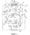
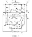
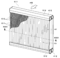
- FIG. 35 is a cross-sectional view taken along the line XXXV-XXXV of FIG. 34.
- the temperature adjusting device 1 of the present embodiment is mounted on an electric vehicle that obtains driving force for traveling from an electric motor.
- the temperature adjusting device 1 adjusts the temperature of the battery 80 that supplies electric power to an electric motor or the like in an electric vehicle, and the temperature of blown air that is blown into the vehicle interior that is the air-conditioned space.
- the battery 80 and the blown air of the present embodiment are objects whose temperature is adjusted by the temperature adjusting device 1.
- the battery 80 is an assembled battery formed by electrically connecting a plurality of battery cells in series or in parallel.
- the battery cell is a rechargeable secondary battery (a lithium ion battery in this embodiment).
- the battery 80 has a plurality of battery cells stacked in a substantially rectangular parallelepiped shape and housed in a dedicated case.
- the temperature of the battery when the temperature becomes low, the chemical reaction is difficult to proceed and the output tends to decrease.
- the battery generates heat during operation (that is, during charging/discharging). Further, the battery is likely to deteriorate at high temperatures. Therefore, it is desirable that the temperature of the battery be maintained within an appropriate temperature range (15° C. or higher and 55° C. or lower in the present embodiment) in which the charge/discharge capacity of the battery can be fully utilized. ..
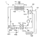
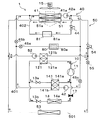
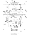
- the temperature adjustment device 1 includes a refrigeration cycle device 10 and a heat medium circuit 40, as shown in the overall configuration diagram of FIG. 1.
- the refrigeration cycle device 10 is a vapor compression refrigeration cycle in which a compressor 11, a condenser 12, an expansion valve 13, and an indoor evaporator 14 are annularly connected.
- the refrigeration cycle device 10 uses an HFO refrigerant (specifically, R1234yf) as a refrigerant.
- the refrigeration cycle device 10 constitutes a subcritical refrigeration cycle in which the pressure of the high-pressure refrigerant discharged from the compressor 11 does not exceed the critical pressure of the refrigerant.
- refrigerating machine oil for lubricating the compressor 11 is mixed in the refrigerant. A part of the refrigerating machine oil circulates in the cycle together with the refrigerant.
- the compressor 11 draws in the refrigerant, compresses it until it becomes high-pressure refrigerant, and discharges it.
- the compressor 11 is an electric compressor in which a fixed displacement type compression mechanism having a fixed discharge capacity is rotationally driven by an electric motor.
- the rotation speed (that is, the refrigerant discharge capacity) of the compressor 11 is controlled by a control signal output from the control device 70 described later.
- the condenser 12 is a heat exchanger for exchanging heat between the high pressure refrigerant discharged from the compressor 11 and the outside air blown from the outdoor blower 15 to condense the high pressure refrigerant.
- the refrigerant passage 12 a in the condenser 12 through which the high-pressure refrigerant flows is a condensing unit that condenses the high-pressure refrigerant discharged from the compressor 11.
- the outdoor blower 15 is an electric blower whose rotation speed (that is, blowing ability) is controlled by a control voltage output from the control device 70.
- the condenser 12 is arranged on the front side in the drive unit room.
- the drive device chamber forms a space in which at least a part of a drive device (for example, an electric motor) for outputting a driving force for traveling is arranged.
- the drive device compartment is arranged on the front side of the vehicle compartment. The outside air is introduced into the drive device chamber through a ventilation hole formed in the front grill at the front of the vehicle.
- the expansion valve 13 is a decompression unit that decompresses the high-pressure refrigerant flowing out of the condenser 12 until it becomes a low-pressure refrigerant.
- the expansion valve 13 is a temperature type expansion that changes the throttle opening degree by a mechanical mechanism so that the superheat degree of the outlet side refrigerant of the indoor evaporator 14 approaches a predetermined reference superheat degree. The valve is adopted.
- the indoor evaporator 14 is a heat exchanger that evaporates the low-pressure refrigerant by exchanging heat between the low-pressure refrigerant decompressed by the expansion valve 13 and the blast air blown into the vehicle interior from an indoor blower (not shown).
- the refrigerant passage 14a of the indoor evaporator 14 through which the low-pressure refrigerant flows is an evaporation unit that evaporates the low-pressure refrigerant.
- the indoor blower is an electric blower whose rotation speed (that is, blowing capacity) is controlled by a control voltage output from the control device 70.
- the heat medium circuit 40 is a heat medium circulation circuit that circulates the heat medium between the cooling water passage 80 a of the battery 80 and the radiator 41.
- a solution containing ethylene glycol, dimethylpolysiloxane, a nanofluid, or the like, an antifreeze solution, or the like can be adopted.
- a water pump 42 is arranged in the heat medium circuit 40.
- the water pump 42 pumps the heat medium flowing out from the radiator 41 to the cooling water passage 80 a of the battery 80.
- the water pump 42 is an electric pump whose rotation speed (that is, water pressure feeding capability) is controlled by a control voltage output from the control device 70.
- the cooling water passage 80 a of the battery 80 is formed in a dedicated case for the battery 80.
- the cooling water passage 80a is an evaporation-side object heat exchange section that allows a heat medium to flow and exchange heat with the battery 80. More specifically, the cooling water passage 80a is a heat exchange unit that causes the heat medium to absorb the heat of the battery 80 (that is, the exhaust heat of the battery 80).
- the cooling water passage 80a has a passage structure in which a plurality of passages are connected in parallel inside a special case. As a result, the cooling water passage 80a is formed so that the exhaust heat of the battery 80 can be absorbed uniformly from the entire area of the battery 80. In other words, the cooling water passage 80a is formed so as to uniformly absorb the heat of all the battery cells and cool all the battery cells.
- the radiator 41 is a first heat exchange unit that causes the heat medium flowing out from the cooling water passage 80a of the battery 80 to exchange heat with the outside air blown from the outdoor blower 15 to radiate the heat of the heat medium to the outside air.
- the heat medium passage 41a through which the heat medium flows in the radiator 41 is a heat radiating portion that radiates the exhaust heat of the battery 80 to the outside air via the heat medium.
- the inlet side of the water pump 42 is connected to the outlet of the heat medium passage 41a.
- the radiator 41 is arranged on the front side in the drive device and on the upstream side in the outside air flow direction with respect to the condenser 12. Therefore, the traveling wind can be applied to the radiator 41 when the vehicle is traveling.
- the radiator 41 and the condenser 12 are formed so that the areas of the heat exchange portions that contribute to heat exchange are substantially equal when viewed from the flow direction of the outside air.
- the radiator 41 and the condenser 12 are arranged close to each other so as to overlap each other when viewed from the flow direction of the outside air.
- the condenser 12 exchanges heat between the high pressure refrigerant discharged from the compressor 11 and the outside air after passing through the radiator 41.
- the radiator 41 exchanges heat between the heat medium flowing out from the cooling water passage 80a of the battery 80 and the outside air before absorbing heat in the condenser 12.
- the refrigerant passage 12a of the condenser 12 dissipates the heat of the high-pressure refrigerant to the outside air after passing through the radiator 41.
- the heat medium passage 41a of the radiator 41 dissipates the exhaust heat of the battery 80 absorbed by the heat medium to the outside air before being absorbed by the condenser 12.
- the control device 70 is composed of a well-known microcomputer including a CPU, a ROM, a RAM and the like and its peripheral circuits. Then, various calculations and processing are performed based on the air-conditioning control program stored in the ROM, and the operations of the various controlled devices 11, 15, 42, etc. connected to the output side are controlled.
- a sensor group for control is connected to the input side of the control device 70.
- the control sensor group includes an inside air temperature detection unit that detects a vehicle compartment temperature (inside air temperature) Tr, a battery temperature detection unit that detects a battery temperature TB that is the temperature of the battery 80, and the like.
- an operation panel (not shown) is connected to the input side of the control device 70.
- the operation panel is provided with, for example, a temperature setting unit for setting the vehicle interior temperature.
- the detection signals of these sensor groups and the operation signals of the operation panel are input to the control device 70.
- the control device 70 of the present embodiment is integrally formed with a control unit that controls various control target devices connected to the output side thereof.
- the configuration (hardware and software) that controls the operation of each control target device constitutes the control unit that controls the operation of each control target device.
- a configuration that controls the operation of the compressor 11 constitutes a compressor control unit.
- the control device 70 controls the operation of the outdoor blower 15, the water pump 42, etc. so that the battery temperature TB is maintained within an appropriate temperature range. Further, the control device 70 controls the operations of the compressor 11, the outdoor blower 15, the indoor blower, and the like so that the vehicle interior temperature Tr approaches the set temperature set by the temperature setting unit.
- the control device 70 When the control device 70 operates the water pump 42, in the heat medium circuit 40, the heat medium pumped from the water pump 42 flows into the cooling water passage 80 a of the battery 80.
- the heat medium flowing into the cooling water passage 80a absorbs the exhaust heat of the battery 80 when flowing through the cooling water passage 80a. Thereby, the battery 80 is cooled.
- the heat medium flowing out from the cooling water passage 80a flows into the heat medium passage 41a of the radiator 41.
- the heat medium flowing into the heat medium passage 41a radiates heat to the outside air. As a result, the heat medium is cooled.
- the heat medium flowing out from the heat medium passage 41a is sucked into the water pump 42 and again sent under pressure to the cooling water passage 80a.
- the high-pressure refrigerant discharged from the compressor 11 flows into the refrigerant passage 12a of the condenser 12.
- the refrigerant flowing into the refrigerant passage 12a radiates heat to the outside air after passing through the radiator 41 and is condensed.
- the liquid-phase high-pressure refrigerant condensed in the condenser 12 flows into the expansion valve 13 and is decompressed. At this time, the opening degree of the expansion valve 13 is adjusted so that the superheat degree of the outlet side refrigerant of the indoor evaporator 14 approaches the reference superheat degree.
- the low pressure refrigerant decompressed by the expansion valve 13 flows into the refrigerant passage 14 a of the indoor evaporator 14.
- the low-pressure refrigerant flowing into the refrigerant passage 14a of the indoor evaporator 14 is heat-exchanged with the blown air blown from the indoor blower and evaporated. Thereby, the blown air is cooled.
- the refrigerant flowing out of the refrigerant passage 14a of the indoor evaporator 14 is sucked into the compressor 11 and compressed again.
- the exhaust heat of the battery 80 can be radiated to the outside air by the radiator 41 via the heat medium.
- the battery 80 can be cooled and the temperature rise of the battery 80 can be suppressed.
- the blower air can be cooled by the indoor evaporator 14 to cool the vehicle interior.
- the condenser 12 is arranged on the downstream side of the radiator 41 in the flow direction of the outside air. That is, the heat medium passage 41a of the radiator 41 radiates the exhaust heat of the battery 80 absorbed by the heat medium to the outside air before the condenser 12 absorbs the heat. Further, the refrigerant passage 12a of the condenser 12 radiates the heat of the high-pressure refrigerant to the outside air after passing through the radiator 41.
- the exhaust heat of the battery 80 can be stably radiated to the outside air via the heat medium without being affected by the operating state of the refrigeration cycle device 10. That is, the battery 80 can be cooled even when the refrigeration cycle device 10 is stopped. As a result, the battery 80 can be efficiently cooled without causing the refrigeration cycle device 10 to consume unnecessary energy.
- the rotation speed of the compressor 11 can be adjusted so that the coefficient of performance (COP) approaches the maximum value regardless of the heat generation amount of the battery 80. That is, in the refrigeration cycle device 10, the rotation speed of the compressor 11 can be adjusted so that the COP is improved regardless of the temperature of the outside air flowing into the condenser 12. Therefore, the blower air can be efficiently cooled by the indoor evaporator 14.
- COP coefficient of performance
- the radiator 41 and the condenser 12 are arranged close to each other so as to overlap each other when viewed from the flow direction of the outside air. Further, the common outdoor blower 15 blows the outside air toward the radiator 41 and the condenser 12. According to this, the mounting space of the radiator 41, the condenser 12, and the outdoor blower 15 can be reduced, and the mounting flexibility can be improved.
- the temperature adjusting device 1 can be used as a battery cooling device used exclusively for cooling the battery 80.
- the refrigeration cycle device 10 can be stopped. Therefore, it is possible to efficiently cool the object (battery 80 in this embodiment) whose temperature is to be adjusted.
- the heat medium circuit 40 described in the first embodiment is referred to as a first heat medium circuit 40 for the sake of clarifying the description. Further, the components of the first heat medium circuit 40 will be described by adding "first" or the like.
- the water pump 42 described in the first embodiment will be referred to as the first battery side water pump 42.
- the heat medium is referred to as the first heat medium.
- the radiator 41 will be referred to as the first radiator 41.
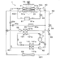
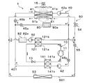
- a water-refrigerant heat exchanger 121 is adopted instead of the condenser 12. Furthermore, in the refrigeration cycle device 10 of the present embodiment, a chiller 141 is used instead of the indoor evaporator 14.
- the water-refrigerant heat exchanger 121 has a refrigerant passage 121a and a heat medium passage 121b.
- the refrigerant passage 121a is a passage through which the high-pressure refrigerant discharged from the compressor 11 flows.
- the heat medium passage 121b is a passage through which the second heat medium circulating in the second heat medium circuit 50 flows.
- the water-refrigerant heat exchanger 121 is a heat exchanger for exchanging heat between the high-pressure refrigerant flowing through the refrigerant passage 121a and the second heat medium flowing through the heat medium passage 121b.
- the high-pressure refrigerant radiates heat to the second heat medium and is condensed.
- the second heat medium absorbs heat from the high-pressure refrigerant and is heated.
- the refrigerant passage 121a is a condensing unit that condenses the high-pressure refrigerant discharged from the compressor 11.
- the heat medium passage 121b is a condensing side heat exchange unit that is thermally connected to the condensing unit to exchange heat between the second heat medium and the high-pressure refrigerant and absorb the heat of the high-pressure refrigerant into the second heat medium. is there.
- the second heat medium circuit 50 is a heat medium circulation circuit that circulates the second heat medium between the heat medium passage 121b of the water-refrigerant heat exchanger 121 and the second radiator 51.
- the same heat medium as the first heat medium can be used as the second heat medium.
- a second heat exchanger side water pump 52 is arranged in the second heat medium circuit 50.
- the second heat exchanger-side water pump 52 pumps the second heat medium flowing out from the second radiator 51 to the heat medium passage 121b of the water-refrigerant heat exchanger 121.
- the basic configuration of the second heat exchanger-side water pump 52 is the same as that of the first battery-side water pump 42.
- the second radiator 51 is a second heat exchange unit that exchanges heat between the second heat medium flowing out from the heat medium passage 121b of the water-refrigerant heat exchanger 121 and the outside air blown from the outdoor blower 15.
- the suction port side of the second heat exchanger-side water pump 52 is connected to the second heat medium passage 51 a of the second radiator 51.
- the second radiator 51 is arranged on the front side in the drive device. That is, the second radiator 51 is arranged on the downstream side of the first radiator 41 in the flow direction of the outside air.
- the first radiator 41 and the second radiator 51 are formed so that the areas of the heat exchange portions that contribute to heat exchange are substantially equal when viewed from the flow direction of the outside air.
- the first radiator 41 and the second radiator 51 are arranged close to each other so as to overlap with each other when viewed from the flow direction of the outside air.
- the second radiator 51 exchanges heat between the second heat medium flowing out from the heat medium passage 121b of the water-refrigerant heat exchanger 121 and the outside air after passing through the first radiator 41.
- the first radiator 41 exchanges heat between the first heat medium flowing out from the cooling water passage 80a of the battery 80 and the outside air before heat exchange with the second heat medium in the second radiator 51.
- the first heat medium passage 41a of the first radiator 41 dissipates the exhaust heat of the battery 80, which has been absorbed by the first heat medium, to the outside air before being absorbed by the second radiator 51.
- the second heat medium passage 51a of the second radiator 51 radiates the heat of the high-pressure refrigerant absorbed by the second heat medium to the outside air after passing through the first radiator 41.
- the chiller 141 has a refrigerant passage 141a and a heat medium passage 141b.
- the refrigerant passage 141a is a passage through which the low-pressure refrigerant whose pressure has been reduced by the expansion valve 13 flows.
- the heat medium passage 141b is a passage through which the first heat medium circulating in the first heat medium circuit 40 flows.
- the chiller 141 is a heat exchanger that exchanges heat between the low-pressure refrigerant flowing through the refrigerant passage 141a and the first heat medium flowing through the heat medium passage 141b.
- the low-pressure refrigerant absorbs heat from the first heat medium and evaporates.
- the second heat medium is absorbed by the low-pressure refrigerant and cooled.
- the refrigerant passage 141a is an evaporation unit that evaporates the low-pressure refrigerant whose pressure has been reduced by the expansion valve 13.
- the heat medium passage 141b is an evaporation side heat exchange unit that is thermally connected to the evaporation unit to exchange heat between the first heat medium and the low-pressure refrigerant, and absorb the heat of the first heat medium into the low-pressure refrigerant. is there.
- the inlet of the cooling water passage 80a of the battery 80 is connected to the outlet of the heat medium passage 141b.
- Other configurations of the first heat medium circuit 40 are the same as those in the first embodiment. Therefore, the first heat medium circuit 40 and the second heat medium circuit 50 of the present embodiment form independent heat medium circuits that do not mix the first heat medium and the second heat medium.
- the battery 80 of the present embodiment is an evaporation side target object, and is included in the target objects whose temperature is adjusted by the temperature adjusting device 1. Further, the cooling water passage 80a is an evaporation side object heat exchange section.
- the control device 70 controls the operation of each control target device connected to the output side so that the battery temperature TB is maintained within an appropriate temperature range.
- the temperature adjusting device 1 of the present embodiment can switch between the first battery cooling mode and the second battery cooling mode according to the battery temperature TB.
- the first battery cooling mode is executed when the battery temperature TB becomes equal to or higher than a predetermined first reference temperature KTB1.
- the first reference temperature KTB1 is set to a value equal to or lower than the upper limit value (30° C. in the present embodiment) within an appropriate temperature range of the battery 80.
- the control device 70 operates the outdoor blower 15 and the first battery side water pump 42. Further, the control device 70 stops the compressor 11 and the second heat exchanger side water pump 52.
- the first heat medium circuit 40 the first heat medium pumped from the first battery side water pump 42 flows into the heat medium passage 141b of the chiller 141. In the first battery cooling mode, the compressor 11 is stopped. Therefore, the first heat medium flows into the cooling water passage 80a of the battery 80 without being cooled in the heat medium passage 141b.
- the first heat medium flowing into the cooling water passage 80a absorbs the exhaust heat of the battery 80 when flowing through the cooling water passage 80a. Thereby, the battery 80 is cooled.
- the first heat medium flowing out from the cooling water passage 80a flows into the first heat medium passage 41a of the first radiator 41.
- the first heat medium flowing into the first heat medium passage 41a radiates heat to the outside air. As a result, the first heat medium is cooled.
- the first heat medium flowing out from the first heat medium passage 41a is sucked into the first battery side water pump 42 and is again pressure fed to the cooling water passage 80a.
- the exhaust heat of the battery 80 can be radiated to the outside air by the first radiator 41 via the first heat medium. Thereby, the battery 80 can be cooled.
- the second battery cooling mode is executed when the battery temperature TB rises above the first reference temperature KTB1 and becomes equal to or higher than the predetermined second reference temperature KTB2.
- the second reference temperature KTB2 is higher than the first reference temperature KTB1 and is set to a value equal to or lower than the upper limit value (45° C. in the present embodiment) within an appropriate temperature range of the battery 80.
- control device 70 operates the outdoor blower 15 and the first battery side water pump 42. Further, the control device 70 operates the compressor 11 and the second heat exchanger side water pump 52.
- the first heat medium pressure-fed from the first battery side water pump 42 is the heat medium passage 141b of the chiller 141 and the cooling water passage of the battery 80.
- 80a, the first heat medium passage 41a of the first radiator 41, and the suction side of the first battery side water pump 42 circulate in this order.
- the exhaust heat of the battery 80 which is absorbed when the first heat medium flows through the cooling water passage 80a of the battery 80, can be radiated to the outside air by the first radiator 41. ..
- the second heat medium pumped from the second heat exchanger side water pump 52 flows into the heat medium passage 121b of the water-refrigerant heat exchanger 121.
- the second heat medium flowing into the heat medium passage 121b absorbs heat from the high pressure refrigerant flowing through the refrigerant passage 121a of the water-refrigerant heat exchanger 121 and is heated.
- the second heat medium flowing out from the heat medium passage 121b flows into the second heat medium passage 51a of the second radiator 51.
- the second heat medium that has flowed into the second heat medium passage 51a radiates heat to the outside air after passing through the first radiator 41. As a result, the second heat medium is cooled.
- the second heat medium flowing out from the second heat medium passage 51a is sucked into the second heat exchanger-side water pump 52 and is again pressure-fed to the heat medium passage 121b.
- the high pressure refrigerant discharged from the compressor 11 flows into the refrigerant passage 121a of the water-refrigerant heat exchanger 121.
- the high-pressure refrigerant flowing into the refrigerant passage 121a radiates heat to the second heat medium flowing through the heat medium passage 121b of the water-refrigerant heat exchanger 121 to be condensed.
- the refrigerant condensed in the refrigerant passage 121a of the water-refrigerant heat exchanger 121 flows into the expansion valve 13 and is depressurized. At this time, the opening degree of the expansion valve 13 is adjusted so that the superheat degree of the outlet side refrigerant of the indoor evaporator 14 approaches the reference superheat degree.
- the low-pressure refrigerant whose pressure has been reduced by the expansion valve 13 flows into the refrigerant passage 141 a of the chiller 141.
- the low-pressure refrigerant flowing into the refrigerant passage 141a of the chiller 141 absorbs heat from the first heat medium flowing through the heat medium passage 141b and evaporates. As a result, the first heat medium flowing through the heat medium passage 141b of the chiller 141 is cooled. The refrigerant flowing out of the refrigerant passage 141a is sucked into the compressor 11 and compressed again.
- the temperature rise of the battery 80 can be suppressed. Furthermore, in the second battery cooling mode, the temperature of the first heat medium flowing into the cooling water passage 80a of the battery 80 can be made lower than that in the first battery cooling mode. Therefore, in the second battery cooling mode, the battery 80 can be cooled with a higher cooling capacity than in the first battery cooling mode.
- the temperature adjusting device 1 of the present embodiment it is possible to cool the battery 80 and suppress the temperature rise of the battery 80.
- the second radiator 51 is arranged on the downstream side of the first radiator 41 in the flow direction of the outside air. That is, the second radiator 51 causes the second heat medium flowing out from the heat medium passage 121b of the water-refrigerant heat exchanger 121 to exchange heat with the outside air after passing through the first radiator 41. Further, the first radiator 41 exchanges heat between the first heat medium flowing out from the cooling water passage 80 a of the battery 80 and the outside air before passing through the second radiator 51.
- the exhaust heat of the battery 80 can be stably radiated to the outside air via the first heat medium without being affected by the operating state of the refrigeration cycle device 10. That is, the battery 80 can be cooled even when the refrigeration cycle device 10 is stopped as in the first battery cooling mode. As a result, the battery 80 can be efficiently cooled without causing the refrigeration cycle device 10 to consume unnecessary energy.
- the temperature adjustment device 1 of the present embodiment includes the chiller 141, the first heat medium is cooled in the second battery cooling mode, and the battery 80 is cooled with a higher cooling capacity than in the first battery cooling mode. can do. Therefore, the battery 80 can be reliably cooled by switching to the second battery cooling mode under the operating condition where the cooling of the battery 80 becomes insufficient in the first battery cooling mode.
- the battery 80 can be cooled efficiently and reliably without consuming unnecessary energy in the refrigeration cycle device 10.
- the first heat medium circuit 40 and the second heat medium circuit 50 form heat medium circuits independent of each other. According to this, there is no change in temperature of the first heat medium due to mixing of the first heat medium and the second heat medium. Therefore, it is easy to adjust the temperature of the first heat medium in the refrigeration cycle device 10. As a result, the temperature of the battery 80 can be more surely maintained within the appropriate temperature range.
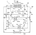
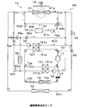
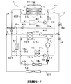
- the present embodiment As shown in FIG. 3, an example in which the configuration of the first heat medium circuit 40 and the configuration of the second heat medium circuit 50 are changed and a heating unit is added to the second embodiment will be described. To do.
- the heating unit heats blown air blown into the vehicle interior. Therefore, the blown air of this embodiment is the fluid to be heated.
- the heating target fluid is included in the target object whose temperature is adjusted by the temperature adjusting device 1.
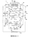
- the first heat medium circuit 40 of the present embodiment has a first battery bypass passage 401.
- the first battery bypass passage 401 bypasses the cooling water passage 80a of the battery 80 to bypass the first heat medium flowing out from the heat medium passage 141b of the chiller 141, and the inlet side of the first heat medium passage 41a of the first radiator 41. Is a heat medium passage leading to.
- the first heat medium circuit 40 of the present embodiment has a first battery side opening/closing valve 45a and a first bypass passage side opening/closing valve 45b.
- the first battery side opening/closing valve 45a and the first bypass passage side opening/closing valve 45b are switching units that switch the circuit configuration of the first heat medium circuit 40.
- the first battery side opening/closing valve 45a is an electromagnetic valve that opens/closes the heat medium passage that allows the first heat medium flowing out from the heat medium passage 141b of the chiller 141 to flow into the cooling water passage 80a of the battery 80.
- the first bypass passage-side opening/closing valve 45b is an electromagnetic valve that opens/closes the first battery bypass passage 401. The operations of the first battery side opening/closing valve 45a and the first bypass passage side opening/closing valve 45b are controlled by the control voltage output from the control device 70.
- the second heat medium circuit 50 of the present embodiment has a second radiator bypass passage 501.
- the second radiator bypass passage 501 bypasses the second radiator 51 of the second heat medium flowing out from the heat medium passage 121b of the water-refrigerant heat exchanger 121 to the suction side of the second heat exchanger side water pump 52. It is a heat medium passage to lead.
- the second heat medium circuit 50 of this embodiment has a heater core 53, a second radiator side flow rate adjusting valve 54, and a second heater core side opening/closing valve 55.
- the heater core 53 is arranged in the second radiator bypass passage 501.
- the second radiator 51 and the heater core 53 are connected in parallel to each other with respect to the flow of the second heat medium flowing out from the heat medium passage 121b.
- the heater core 53 is a heat exchanger that heats the blown air by exchanging heat between the second heat medium flowing out from the heat medium passage 121b and the blown air blown from the indoor blower (not shown) into the vehicle interior.
- the second radiator side flow rate adjusting valve 54 is arranged in a heat medium passage for guiding the second heat medium flowing out from the heat medium passage 121b of the water-refrigerant heat exchanger 121 to the second heat medium passage 51a of the second radiator 51. There is.
- the second radiator side flow rate adjustment valve 54 adjusts the flow rate of the second heat medium flowing into the second heat medium passage 51 a of the second radiator 51.
- the second radiator side flow rate adjusting valve 54 is an electric variable throttle mechanism.
- the second radiator-side flow rate adjusting valve 54 has a fully open function that functions as a simple heat medium passage with almost no flow rate adjusting action by fully opening the valve opening, and a fully open function to close the valve opening. It has a fully closed function of closing the medium passage.
- the operation of the second radiator side flow rate adjusting valve 54 is controlled by a control signal output from the control device 70.
- the second heater core side opening/closing valve 55 is arranged in the heat medium passage that guides the second heat medium flowing out from the heat medium passage 121 b of the water-refrigerant heat exchanger 121 to the heater core 53.
- the second heater core side opening/closing valve 55 is an electromagnetic valve that opens/closes the second radiator bypass passage 501.
- the basic configuration of the second heater core side opening/closing valve 55 is the same as that of the first battery side opening/closing valve 45a and the like. Other configurations of the temperature adjusting device 1 are similar to those of the second embodiment.
- the second heat medium heated in the heat medium passage 121b of the water-refrigerant heat exchanger 121 is caused to flow into the heater core 53, so that the heater core 53 blows air. Can be heated.
- the heating unit is configured by the second heat medium circuit 50 having the water-refrigerant heat exchanger 121 and the heater core 53. More specifically, in the second heat medium circuit 50, the heating unit is configured by a circuit that circulates the second heat medium between the water-refrigerant heat exchanger 121 and the heater core 53.
- the control device 70 controls the operation of the control target device so that the battery temperature TB is maintained within an appropriate temperature range. Further, the control device 70 controls the operation of the controlled device so that the vehicle interior temperature Tr approaches the set temperature set by the temperature setting unit.
- the operation mode can be switched according to the battery temperature TB and the passenger compartment temperature Tr. Each operation mode will be described below.
- the first battery cooling mode is executed when the battery temperature TB is equal to or higher than the first reference temperature KTB1 and the vehicle compartment temperature Tr is higher than the set temperature. ..
- the battery temperature TB is equal to or higher than the first reference temperature KTB1
- the battery 80 needs to be cooled.
- the passenger compartment temperature Tr is higher than the set temperature, it is not necessary to heat the passenger compartment. Therefore, it is not necessary to operate the refrigeration cycle device 10 in the first battery cooling mode.
- the control device 70 opens the first battery side opening/closing valve 45a and closes the first bypass passage side opening/closing valve 45b. Further, the control device 70 operates the outdoor blower 15 and the first battery side water pump 42. Further, the control device 70 stops the second heat exchanger side water pump 52 and the compressor 11.
- the first heat medium circuit 40 the first heat medium circulates, as in the second embodiment.
- the exhaust heat of the battery 80 which is absorbed when the first heat medium flows through the cooling water passage 80a of the battery 80, can be radiated to the outside air by the first radiator 41. ..
- the second heat exchanger side water pump 52 is stopped, so the second heat medium does not circulate. Further, in the refrigeration cycle device 10, since the compressor 11 is stopped, the refrigerant does not circulate.
- the battery 80 can be cooled as in the first battery cooling mode described in the second embodiment.
- the second battery cooling mode is executed when the battery temperature TB is the second reference temperature KTB2 or higher and the vehicle interior temperature Tr is higher than the set temperature. ..
- the battery 80 may not be sufficiently cooled only by circulating the first heat medium in the first heat medium circuit 40. Therefore, in the second battery cooling mode, the refrigeration cycle device 10 is operated.
- the control device 70 opens the first battery side opening/closing valve 45a and closes the first bypass passage side opening/closing valve 45b. Further, the control device 70 operates the outdoor blower 15 and the first battery side water pump 42. Further, the control device 70 fully opens the second radiator side flow rate adjusting valve 54 and closes the second heater core side opening/closing valve 55. Further, the control device 70 operates the second heat exchanger side water pump 52 and the compressor 11.
- the first heat medium circuit 40 the first heat medium circulates as in the first battery cooling mode.
- the exhaust heat of the battery 80 which is absorbed when the first heat medium flows through the cooling water passage 80a of the battery 80, can be radiated to the outside air by the first radiator 41. ..
- the second heat medium pressure-fed from the second heat exchanger side water pump 52 is the water-refrigerant heat exchanger 121 as in the second battery cooling mode of the second embodiment.
- the heat medium passage 121b, the second heat medium passage 51a of the second radiator 51, and the suction side of the second heat exchanger side water pump 52 circulate in this order.
- the heat that the second heat medium has absorbed from the high-pressure refrigerant in the water-refrigerant heat exchanger 121 can be radiated to the outside air by the second radiator 51.
- the refrigerant discharged from the compressor 11 causes the refrigerant passage 121a of the water-refrigerant heat exchanger 121, the expansion valve 13, and the chiller 141 to operate.
- the refrigerant passage 141a and the suction side of the compressor 11 circulate in this order. Accordingly, in the refrigeration cycle device 10, the heat absorbed by the refrigerant from the first heat medium in the chiller 141 can be radiated to the second heat medium in the water-refrigerant heat exchanger 121.
- the temperature of the first heat medium flowing into the cooling water passage 80a of the battery 80 is lower than that in the first battery cooling mode. Can be made. As a result, the battery 80 can be cooled with a higher cooling capacity than in the first battery cooling mode.
- (C) Heating/Cooling Mode The heating/cooling mode is executed when the battery temperature TB is equal to or higher than the first reference temperature KTB1 and the vehicle compartment temperature Tr is lower than the set temperature. When the vehicle compartment temperature Tr is lower than the set temperature, it is necessary to heat the vehicle compartment.
- control device 70 opens the first battery side opening/closing valve 45a and closes the first bypass passage side opening/closing valve 45b. Further, the control device 70 operates the outdoor blower 15 and the first battery side water pump 42.
- control device 70 adjusts the opening degree of the second radiator side flow rate adjusting valve 54 and opens the second heater core side opening/closing valve 55.
- the opening degree of the second radiator side flow rate adjusting valve 54 is adjusted so that the vehicle compartment temperature Tr approaches the set temperature. Further, the control device 70 operates the second heat exchanger side water pump 52 and the compressor 11.
- the first heat medium circuit 40 the first heat medium circulates as in the first battery cooling mode.
- the exhaust heat of the battery 80 which is absorbed when the first heat medium flows through the cooling water passage 80a of the battery 80, can be radiated to the outside air by the first radiator 41. ..
- the second heat medium pumped from the second heat exchanger side water pump 52 is heated in the heat medium passage 121b of the water-refrigerant heat exchanger 121.
- the second heat medium flowing into the heater core 53 exchanges heat with the blown air blown from the indoor blower to radiate heat. Thereby, the blown air is heated.
- the second heat medium flowing out from the heater core 53 joins with the second heat medium flowing out from the second heat medium passage 51a.
- the residual second heat medium heated in the heat medium passage 121b flows into the second heat medium passage 51a of the second radiator 51 via the second radiator side flow rate adjusting valve 54.
- the second heat medium that has flowed into the second heat medium passage 51a radiates heat to the outside air after passing through the first radiator 41. As a result, the second heat medium is cooled.
- the opening degree of the second radiator side flow rate adjusting valve 54 is set so that the heat of the second heat medium in the second radiator 51 is not excessively radiated to the outside air in order to bring the vehicle compartment temperature Tr close to the set temperature. Adjusted.
- the second heat medium flowing out from the second heat medium passage 51 a merges with the second heat medium flowing out from the heater core 53, and is sucked into the second heat exchanger side water pump 52.
- the refrigerant circulates, as in the second battery cooling mode. Accordingly, in the refrigeration cycle device 10, the heat absorbed by the refrigerant from the first heat medium in the chiller 141 can be radiated to the second heat medium in the water-refrigerant heat exchanger 121.
- the battery 80 can be cooled with a high cooling capacity as in the second battery cooling mode. Furthermore, the air blown by the heater core 53 can be heated to heat the passenger compartment.
- (D) Heating operation mode The heating operation mode is executed when the battery temperature TB is lower than the first reference temperature KTB1 and the vehicle interior temperature Tr is lower than the set temperature. When the battery temperature TB is lower than the first reference temperature KTB1, it is not necessary to cool the battery 80.
- control device 70 closes the first battery side opening/closing valve 45a and opens the first bypass passage side opening/closing valve 45b. Further, the control device 70 operates the outdoor blower 15 and the first battery side water pump 42.
- control device 70 adjusts the opening degree of the second radiator side flow rate adjusting valve 54 and opens the second heater core side opening/closing valve 55.
- the opening degree of the second radiator side flow rate adjusting valve 54 is adjusted so that the vehicle compartment temperature Tr approaches the set temperature. Further, the control device 70 operates the second heat exchanger side water pump 52 and the compressor 11.
- the first heat medium pumped from the first battery side water pump 42 flows into the heat medium passage 141b of the chiller 141.
- the first heat medium flowing into the heat medium passage 141b of the chiller 141 is absorbed by the low-pressure refrigerant flowing through the refrigerant passage 141a of the chiller 141 and is cooled.
- the first heat medium flowing out from the heat medium passage 141b flows into the first heat medium passage 41a of the first radiator 41 via the first battery bypass passage 401. Therefore, in the heating operation mode, the first heat medium does not absorb the exhaust heat of the battery 80.
- the first heat medium flowing into the first heat medium passage 41 a exchanges heat with the outside air blown from the outdoor blower 15.
- the low-temperature first heat medium flows into the first heat medium passage 41a. Therefore, in the first radiator 41, the first heat medium absorbs heat from the outside air and the temperature rises to about the outside air temperature.
- the first heat medium flowing out from the first heat medium passage 41a is sucked into the first battery side water pump 42 and is again pressure-fed to the heat medium passage 141b.
- the second heat medium pumped from the second heat exchanger-side water pump 52 is connected to the refrigerant passage 121a of the water-refrigerant heat exchanger 121 and the second passage.
- the heater core side opening/closing valve 55, the heater core 53, and the suction port of the second heat exchanger side water pump 52 circulate in this order.
- the refrigerant passage 121a of the water-refrigerant heat exchanger 121, the second radiator side flow rate adjusting valve 54, the second heat medium passage 51a of the second radiator 51, and the suction port of the second heat exchanger side water pump 52 are circulated in this order. To do.
- part of the heat absorbed by the second heat medium from the high-pressure refrigerant in the water-refrigerant heat exchanger 121 can be radiated to the blown air by the heater core 53. it can. Further, the residual heat can be radiated to the outside air by the second radiator 51.
- the refrigerant circulates, as in the second battery cooling mode.
- the heat absorbed by the refrigerant from the first heat medium in the chiller 141 can be radiated to the second heat medium in the water-refrigerant heat exchanger 121.
- the blown air can be heated by the heater core 53 without cooling the battery 80.
- the vehicle interior can be heated.
- the temperature adjusting device 1 of the present embodiment can switch between the first battery cooling mode and the second battery cooling mode. Therefore, similarly to the second embodiment, it is possible to efficiently and reliably cool the battery 80 and suppress an increase in the temperature of the battery 80 without consuming unnecessary energy in the refrigeration cycle device 10. it can.
- the temperature adjusting device 1 of the present embodiment is provided with the second heat medium circuit 50 having the water-refrigerant heat exchanger 121 and the heater core 53 as the heating unit. Further, in the refrigeration cycle device 10, the heat absorbed from the first heat medium by the chiller 141 is radiated to the second heat medium by the water-refrigerant heat exchanger 121. Therefore, in the heater core 53, the blown air can be heated via the second heat medium using the high pressure refrigerant as a heat source.
- the first radiator 41 causes heat exchange between the first heat medium and the outside air before passing through the second radiator 51.
- the temperature of the first heat medium flowing out from the first heat medium passage 41a is brought close to the ambient temperature. be able to. That is, even if the heating/cooling mode and the heating operation mode are switched, the temperature of the first heat medium flowing into the heat medium passage 141b of the chiller 141 can be brought close to the outside air temperature.
- the temperature adjusting device 1 of the present embodiment stable heating performance can be exhibited even when switching between the heating/cooling mode and the heating operation mode.
- the inlet side of the cooling water passage 80a of the battery 80 is connected to the discharge port of the first battery side water pump 42.
- the inlet side of the first heat medium passage 41a of the first radiator 41 and the inlet side of the heat medium passage 141b of the chiller 141 are connected to the outlet of the cooling water passage 80a.
- the first battery side opening/closing valve 45a of the present embodiment is arranged so as to open/close the heat medium passage that guides the first heat medium flowing out from the first heat medium passage 41a to the suction port of the first battery side water pump 42. ing.
- the first heat medium flowing out from the cooling water passage 80a of the battery 80 bypasses the first heat medium passage 41a to the inlet side of the heat medium passage 141b of the chiller 141.
- the first radiator 41 and the chiller 141 of the present embodiment are connected in parallel to each other with respect to the flow of the first heat medium flowing out from the cooling water passage 80a.
- the outlet of the heat medium passage 141b is connected to the suction port side of the first battery side water pump 42.
- the first bypass passage opening/closing valve 45b is arranged to open/close the heat medium passage that allows the first heat medium flowing out of the heat medium passage 141b to flow into the suction port of the first battery side water pump 42.
- Other configurations are similar to those of the third embodiment. Therefore, the heating unit of the present embodiment is configured by the second heat medium circuit 50, as in the third embodiment.
- the operation of the temperature adjusting device 1 of the present embodiment having the above configuration will be described.
- three operation modes can be switched according to the battery temperature TB and the vehicle compartment temperature Tr. Each operation mode will be described below.
- the first battery cooling mode is executed when the battery temperature TB is equal to or higher than the first reference temperature KTB1 and the vehicle compartment temperature Tr is higher than the set temperature. ..
- the control device 70 opens the first battery side opening/closing valve 45a and closes the first bypass passage side opening/closing valve 45b. Further, the control device 70 operates the outdoor blower 15 and the first battery side water pump 42. Further, the control device 70 stops the second heat exchanger side water pump 52 and the compressor 11.
- the first heat medium discharged from the first battery side water pump 42 flows into the cooling water passage 80a of the battery 80.
- the first heat medium flowing into the cooling water passage 80a absorbs the exhaust heat of the battery 80 and is heated when flowing through the cooling water passage 80a. Thereby, the battery 80 is cooled.
- the first heat medium flowing out from the cooling water passage 80a flows into the first heat medium passage 41a of the first radiator 41.
- the first heat medium flowing into the first heat medium passage 41a radiates heat to the outside air. As a result, the first heat medium is cooled.
- the first heat medium flowing out from the first heat medium passage 41a is sucked into the first battery side water pump 42 and is again pressure fed to the cooling water passage 80a.
- the second heat exchanger side water pump 52 is stopped, so the second heat medium is not circulated. Further, in the refrigeration cycle device 10, since the compressor 11 is stopped, the refrigerant does not circulate.
- the temperature rise of the battery 80 can be suppressed as in the first battery cooling mode described in the second embodiment.
- the second battery cooling mode is executed when the battery temperature TB is the second reference temperature KTB2 or higher and the vehicle interior temperature Tr is higher than the set temperature. ..
- the control device 70 opens the first battery side opening/closing valve 45a and opens the first bypass passage side opening/closing valve 45b. Further, the control device 70 operates the outdoor blower 15 and the first battery side water pump 42. Further, the control device 70 fully opens the second radiator side flow rate adjusting valve 54 and closes the second heater core side opening/closing valve 55. Further, the control device 70 operates the second heat exchanger side water pump 52 and the compressor 11.
- the first heat medium pumped from the first battery side water pump 42 flows into the cooling water passage 80a of the battery 80.
- the first heat medium that has flowed into the cooling water passage 80a absorbs the exhaust heat of the battery 80 and is heated. Thereby, the battery 80 is cooled.
- a part of the first heat medium heated in the cooling water passage 80a flows into the first heat medium passage 41a of the first radiator 41.
- a part of the first heat medium that has flowed into the first heat medium passage 41a radiates heat to the outside air after passing through the first radiator 41. As a result, the first heat medium is cooled.
- the first heat medium flowing out from the first heat medium passage 41 a merges with the first heat medium flowing out from the heat medium passage 141 b of the chiller 141.
- the remaining first heat medium heated in the cooling water passage 80a flows into the heat medium passage 141b of the chiller 141.
- the first heat medium flowing into the heat medium passage 141b of the chiller 141 is absorbed by the low-pressure refrigerant flowing through the refrigerant passage 141a of the chiller 141 and is cooled. As a result, the temperature of the first heat medium becomes lower than the outside air temperature.
- the first heat medium flowing out from the heat medium passage 141b merges with the first heat medium flowing out from the first heat medium passage 41a, and is sucked into the first battery side water pump 42. Therefore, in the second battery cooling mode, the temperature of the first heat medium discharged from the first battery side water pump 42 and flowing into the cooling water passage 80a of the battery 80 becomes lower than that in the first battery cooling mode.
- the second heat medium circulates, as in the second battery cooling mode of the third embodiment.
- the heat that the second heat medium has absorbed from the high-pressure refrigerant in the water-refrigerant heat exchanger 121 can be radiated to the outside air by the second radiator 51.
- the refrigerant circulates, as in the second battery cooling mode of the third embodiment. Accordingly, in the refrigeration cycle device 10, the heat absorbed by the refrigerant from the first heat medium in the chiller 141 can be radiated to the second heat medium in the water-refrigerant heat exchanger 121.
- the temperature of the first heat medium flowing into the cooling water passage 80a of the battery 80 is made lower than that in the first battery cooling mode, and the battery 80 has a higher cooling capacity than that in the first battery cooling mode. Can be cooled.
- the heating/cooling mode is executed when the battery temperature TB is equal to or higher than the first reference temperature KTB1 and the vehicle compartment temperature Tr is lower than the set temperature.
- the control device 70 opens the first battery side opening/closing valve 45a and opens the first bypass passage side opening/closing valve 45b. Further, the control device 70 operates the outdoor blower 15 and the first battery side water pump 42.
- control device 70 adjusts the opening degree of the second radiator side flow rate adjusting valve 54 and opens the second heater core side opening/closing valve 55.
- the opening degree of the second radiator side flow rate adjusting valve 54 is adjusted so that the vehicle compartment temperature Tr approaches the set temperature. Further, the control device 70 operates the second heat exchanger side water pump 52 and the compressor 11.
- the first heat medium pumped from the first battery-side water pump 42 causes the cooling water passage 80a of the battery 80 and the first radiator 41 of the first radiator 41 to cool.
- the first heat medium passage 41a, the first battery side opening/closing valve 45a, and the suction port of the first battery side water pump 42 circulate in this order.
- the heat medium passage 141b of the chiller 141, the first bypass passage side opening/closing valve 45b, and the suction port of the first battery side water pump 42 circulate in this order.
- the first heat medium circuit 40 a part of the heat absorbed by the first heat medium from the battery 80 can be radiated to the outside air by the first radiator 41. Furthermore, the residual heat can be absorbed by the low-pressure refrigerant in the chiller 141.
- the second heat medium circulates, as in the heating/cooling mode of the second embodiment.
- part of the heat absorbed by the second heat medium from the high-pressure refrigerant in the water-refrigerant heat exchanger 121 can be radiated to the blown air by the heater core 53. it can. Further, the residual heat can be radiated to the outside air by the second radiator 51.
- the refrigerant circulates, as in the second battery cooling mode.
- the heat absorbed by the refrigerant from the first heat medium in the chiller 141 can be radiated to the second heat medium in the water-refrigerant heat exchanger 121.
- the battery 80 can be cooled with a high cooling capacity as in the second battery cooling mode. Further, the heater core 53 can heat the blown air to heat the vehicle interior.
- the temperature adjusting device 1 of the present embodiment can switch between the first battery cooling mode and the second battery cooling mode. Therefore, similarly to the second embodiment, it is possible to efficiently and reliably cool the battery 80 and suppress an increase in the temperature of the battery 80 without consuming unnecessary energy in the refrigeration cycle device 10. it can.
- the temperature adjusting device 1 of the present embodiment is provided with the second heat medium circuit 50 having the water-refrigerant heat exchanger 121 and the heater core 53 as the heating unit. Therefore, as in the third embodiment, it is possible to heat the blown air to heat the vehicle interior.
- the refrigeration cycle device 10 of the present embodiment has an indoor condenser 122, a bypass passage 101 for the refrigeration cycle device, an opening/closing valve 16, and a chiller 141 similar to that of the second embodiment.
- the indoor condenser 122 is a heat exchanger for heating that heats the blown air by exchanging heat between the high-pressure refrigerant discharged from the compressor 11 and the blown air blown into the vehicle interior from an indoor blower (not shown).
- the indoor condenser 122 is a heating unit that heats blown air using the high-pressure refrigerant as a heat source.
- An inlet side of the refrigerant passage 12 a of the condenser 12 is connected to the refrigerant outlet of the indoor condenser 122.
- the bypass passage 101 is a refrigerant passage that guides the high-pressure refrigerant discharged from the compressor 11 to the inlet side of the refrigerant passage 12a of the condenser 12 by bypassing the indoor condenser 122.
- the on-off valve 16 is an on-off valve that opens and closes the bypass passage 101.
- the basic structure of the on-off valve 16 is the same as the second heater core-side on-off valve 55 of the second heat medium circuit 50 described in the third embodiment.
- the pressure loss that occurs when the refrigerant passes through the bypass passage 101 is extremely smaller than the pressure loss that occurs when the refrigerant passes through the refrigerant passage of the indoor condenser 122. Therefore, when the opening/closing valve 16 is open, almost all the high-pressure refrigerant discharged from the compressor 11 flows into the condenser 12 via the bypass passage 101. Further, when the on-off valve 16 is closed, all the high pressure refrigerant discharged from the compressor 11 flows into the refrigerant passage of the indoor condenser 122.
- the first heat medium circuit 40 of the present embodiment has the same first battery bypass passage 401, the first battery side opening/closing valve 45a, and the first bypass passage side opening/closing valve 45b as in the third embodiment.
- the first battery side opening/closing valve 45a of the present embodiment is arranged in a heat medium passage extending from a branch portion that branches the flow of the refrigerant flowing out of the heat medium passage 141b of the chiller 141 to the inlet of the cooling water passage 80a of the battery 80.
- the first battery side opening/closing valve 45a may be arranged in the heat medium passage extending from the outlet of the cooling water passage 80a of the battery 80 to the confluence portion.
- the merging portion is a part that joins the flow of the refrigerant flowing out from the cooling water passage 80 a of the battery 80 and the flow of the refrigerant flowing through the first battery bypass passage 401.
- Other configurations of the temperature adjusting device 1 are similar to those of the first embodiment.
- the control device 70 controls the operation of the control target device so that the battery temperature TB is maintained within an appropriate temperature range. Further, the control device 70 controls the operation of the controlled device so that the vehicle interior temperature Tr approaches the set temperature set by the temperature setting unit.
- the first battery cooling mode is executed when the battery temperature TB is equal to or higher than the first reference temperature KTB1 and the vehicle compartment temperature Tr is higher than the set temperature. ..
- the control device 70 opens the first battery side opening/closing valve 45a and closes the first bypass passage side opening/closing valve 45b. Further, the control device 70 operates the outdoor blower 15 and the first battery side water pump 42. Further, the control device 70 opens the opening/closing valve 16 and stops the compressor 11.
- the first heat medium circuit 40 the first heat medium circulates, as in the second embodiment.
- the exhaust heat of the battery 80 which is absorbed when the first heat medium flows through the cooling water passage 80a of the battery 80, can be radiated to the outside air by the first radiator 41. ..
- the compressor 11 since the compressor 11 is stopped, the refrigerant does not circulate.
- the temperature rise of the battery 80 can be suppressed as in the first battery cooling mode described in the second embodiment.
- the second battery cooling mode is executed when the battery temperature TB is the second reference temperature KTB2 or higher and the vehicle interior temperature Tr is higher than the set temperature. ..
- the control device 70 opens the first battery side opening/closing valve 45a and closes the first bypass passage side opening/closing valve 45b. Further, the control device 70 operates the outdoor blower 15 and the first battery side water pump 42. Further, the control device 70 opens the open/close valve 16 and operates the compressor 11.
- the first heat medium circuit 40 the first heat medium circulates as in the first battery cooling mode.
- the exhaust heat of the battery 80 which is absorbed when the first heat medium flows through the cooling water passage 80a of the battery 80, can be radiated to the outside air by the first radiator 41. ..
- the high-pressure refrigerant discharged from the compressor 11 flows into the refrigerant passage 12a of the condenser 12 via the opening/closing valve 16.
- the refrigerant flowing into the refrigerant passage 12a radiates heat to the outside air after passing through the radiator 41 and is condensed.
- the liquid-phase high-pressure refrigerant condensed in the condenser 12 flows into the expansion valve 13 and is decompressed.
- the opening degree of the expansion valve 13 is adjusted so that the superheat degree of the outlet side refrigerant of the indoor evaporator 14 approaches the reference superheat degree.
- the low-pressure refrigerant decompressed by the expansion valve 13 flows into the refrigerant passage 141a of the chiller 141.
- the low-pressure refrigerant flowing into the refrigerant passage 141a of the chiller 141 absorbs heat from the first heat medium flowing through the heat medium passage 141b of the chiller 141 and evaporates. As a result, the first heat medium is cooled.
- the refrigerant flowing out from the refrigerant passage 141a of the chiller 141 is sucked into the compressor 11 and compressed again.
- the battery 80 can be cooled with a higher cooling capacity than in the first battery cooling mode, as in the second battery cooling mode described in the second embodiment.
- the heating/cooling mode is executed when the battery temperature TB is equal to or higher than the first reference temperature KTB1 and the vehicle compartment temperature Tr is lower than the set temperature.
- the control device 70 opens the first battery side opening/closing valve 45a and closes the first bypass passage side opening/closing valve 45b. Further, the control device 70 operates the outdoor blower 15 and the first battery side water pump 42. Further, the control device 70 closes the opening/closing valve 16 and operates the compressor 11.
- the first heat medium circuit 40 the first heat medium circulates as in the first battery cooling mode.
- the exhaust heat of the battery 80 which is absorbed when the first heat medium flows through the cooling water passage 80a of the battery 80, can be radiated to the outside air by the first radiator 41. ..
- the high pressure refrigerant discharged from the compressor 11 flows into the indoor condenser 122.
- the high-pressure refrigerant flowing into the indoor condenser 122 exchanges heat with the air blown from the indoor blower to radiate heat. Thereby, the blown air is heated.
- the high-pressure refrigerant flowing out of the indoor condenser 122 flows into the refrigerant passage 12 a of the condenser 12.
- the subsequent operation of the refrigeration cycle apparatus 10 is similar to that in the second battery cooling mode.
- the battery 80 can be cooled with a high cooling capacity as in the second battery cooling mode. Further, the interior condenser 122 can heat the blown air to heat the vehicle interior.
- Heating operation mode is executed when the battery temperature TB is lower than the first reference temperature KTB1 and the vehicle interior temperature Tr is lower than the set temperature.
- the control device 70 closes the first battery side opening/closing valve 45a and opens the first bypass passage side opening/closing valve 45b. Further, the control device 70 operates the outdoor blower 15 and the first battery side water pump 42. Further, the control device 70 closes the opening/closing valve 16 and operates the compressor 11.
- the first heat medium pumped from the first battery side water pump 42 is the heat medium passage 141b of the chiller 141 and the first battery.
- the bypass passage 401, the first heat medium passage 41 a of the first radiator 41, and the suction port of the first battery side water pump 42 circulate in this order. Accordingly, in the first heat medium circuit 40, the heat absorbed by the first heat medium from the outside air by the first radiator 41 can be radiated to the low-pressure refrigerant by the chiller 141.
- the high-pressure refrigerant discharged from the compressor 11 causes the indoor condenser 122, the refrigerant passage 12a of the condenser 12, the expansion valve 13, the refrigerant passage 141a of the chiller 141, It circulates in the order of the suction port of the compressor 11.
- the heat absorbed by the refrigerant from the first heat medium in the chiller 141 can be radiated to the blown air in the indoor condenser 122.
- the blower air can be heated by the indoor condenser 122 without cooling the battery 80.
- the vehicle interior can be heated.
- the temperature adjusting device 1 of the present embodiment can switch between the first battery cooling mode and the second battery cooling mode. Therefore, similarly to the second embodiment, it is possible to efficiently and reliably cool the battery 80 and suppress an increase in the temperature of the battery 80 without consuming unnecessary energy in the refrigeration cycle device 10. it can.
- the temperature adjusting device 1 of the present embodiment is provided with the indoor condenser 122 as a heating unit. Further, in the refrigeration cycle apparatus 10, the chiller 141 absorbs heat from the first heat medium and evaporates the low-pressure refrigerant, and the compressor 11 compresses the low-pressure refrigerant to a high-pressure refrigerant and discharges it.
- the high-pressure refrigerant discharged from the compressor 11 is used as a heat source to directly heat the blown air in the indoor condenser 122 to heat the passenger compartment.
- the first radiator 41 heat-exchanges the first heat medium with the outside air before passing through the second radiator 51.
- the temperature of the first heat medium flowing out from the first heat medium passage 41a is brought close to the ambient temperature. be able to. That is, even if the heating/cooling mode and the heating operation mode are switched, the temperature of the first heat medium flowing into the heat medium passage 141b of the chiller 141 can be brought close to the outside air temperature.
- the temperature adjusting device 1 of the present embodiment stable heating performance can be exhibited even when switching between the heating/cooling mode and the heating operation mode.
- the inlet side of the first heat medium passage 41a of the first radiator 41 is connected to the discharge port of the first battery side water pump 42.
- the inlet side of the cooling water passage 80a of the battery 80 is connected to the outlet of the first heat medium passage 41a. Further, the outlet of the cooling water passage 80a is connected to the suction port side of the first battery side water pump 42.
- the heat medium passage 141b of the chiller 141 is not connected to the first heat medium circuit 40 of the present embodiment. Therefore, the first heat medium does not flow through the heat medium passage 141b of the chiller 141.
- the second heat medium circuit 50 of the present embodiment has a second heater core bypass passage 502 in addition to the second heat medium circuit 50 described in the third embodiment. Further, the second heat medium circuit 50 of the present embodiment has a second chiller side water pump 52a and a second chiller side opening/closing valve 55a.
- the second heater core bypass passage 502 bypasses the heater core 53 and guides the second heat medium flowing out from the second heat medium passage 51a of the second radiator 51 to the inlet side of the second heat medium passage 51a of the second radiator 51. It is a heat medium passage.
- the heat medium passage 141b of the chiller 141 is connected to the second heater core bypass passage 502.
- the second chiller-side water pump 52a pumps the second heat medium flowing out from the heat medium passage 141b of the chiller 141 to the inlet side of the second heat medium passage 51a of the second radiator 51.
- the basic configuration of the second chiller side water pump 52a is the same as that of the second heat exchanger side water pump 52.
- the second chiller-side opening/closing valve 55a is arranged in the heat medium passage that guides the second heat medium flowing out from the heat medium passage 141b of the chiller 141 to the second radiator 51.
- the basic configuration of the second chiller side opening/closing valve 55a is the same as that of the second heater core side opening/closing valve 55. Other configurations are similar to those of the second embodiment.
- control device 70 controls the operation of the outdoor blower 15 and the first battery side water pump 42 as in the first embodiment so that the battery temperature TB is maintained within an appropriate temperature range. ..
- control device 70 opens the second radiator side flow rate adjusting valve 54 in the same manner as the heating/cooling mode of the third embodiment so that the vehicle interior temperature Tr approaches the set temperature set by the temperature setting unit. Adjust. Further, the second heater core side opening/closing valve 55 and the second chiller side opening/closing valve 55a are opened. Further, the control device 70 operates the second heat exchanger side water pump 52 and the compressor 11.
- the heat medium pumped from the first battery side water pump 42 flows into the first heat medium passage 41a of the first radiator 41.
- the first heat medium flowing into the first heat medium passage 41 a of the first radiator 41 exchanges heat with the outside air blown from the outdoor blower 15. As a result, the temperature of the first heat medium approaches the ambient temperature.
- the first heat medium flowing out from the first heat medium passage 41a flows into the cooling water passage 80a of the battery 80.
- the heat medium flowing into the cooling water passage 80a absorbs the exhaust heat of the battery 80 when flowing through the cooling water passage 80a. Thereby, the battery 80 is cooled.
- the heat medium flowing out from the cooling water passage 80a is sucked into the first battery side water pump 42 and again sent under pressure to the first heat medium passage 41a.
- the second heat medium circulates, as in the heating/cooling mode of the second embodiment.
- the second heat medium pumped from the second chiller side water pump 52a flows out from the second heater core bypass passage 502 via the second chiller side opening/closing valve 55a. To do.
- the second heat medium flowing out from the second heater core bypass passage 502 joins the second heat medium flowing out from the second radiator side flow rate adjusting valve 54, and flows into the second heat medium passage 51 a of the second radiator 51.
- the second heat medium flowing into the second heat medium passage 51a exchanges heat with the outside air after passing through the first radiator 41, and absorbs the heat of the outside air.
- a part of the second heat medium out of the second heat medium passage 51a flows into the second heater core bypass passage 502 and is guided to the heat medium passage 141b of the chiller 141.
- the second heat medium flowing into the heat medium passage 141b is cooled by exchanging heat with the low-pressure refrigerant flowing through the refrigerant passage 141a of the chiller 141.
- part of the heat absorbed by the second heat medium from the high-pressure refrigerant in the water-refrigerant heat exchanger 121 is converted into blast air by the heater core 53. Can dissipate heat.
- the refrigerant circulates, as in the second battery cooling mode of the second embodiment. Accordingly, in the refrigeration cycle device 10, the heat absorbed by the refrigerant from the second heat medium in the chiller 141 can be radiated to the second heat medium in the water-refrigerant heat exchanger 121.
- the battery 80 can be cooled without being affected by the operating state of the refrigeration cycle device 10 as in the first embodiment. Therefore, the battery 80 can be efficiently cooled without consuming unnecessary energy in the refrigeration cycle device 10.
- the temperature adjusting device 1 of the present embodiment is provided with the second heat medium circuit 50 having the water-refrigerant heat exchanger 121 and the heater core 53 as the heating unit. Further, in the refrigeration cycle device 10, the heat absorbed from the second heat medium by the chiller 141 is radiated to the second heat medium by the water-refrigerant heat exchanger 121. Therefore, in the heater core 53, the blown air can be heated via the second heat medium using the high pressure refrigerant as a heat source.
- the second radiator 51 exchanges heat between the second heat medium and the outside air after passing through the first radiator 41. That is, in the second radiator 51, the second heat medium and the outside air heated by the exhaust heat of the battery 80 are heat-exchanged. Therefore, the temperature of the second heat medium flowing into the heat medium passage 141b of the chiller 141 can be raised more than when the second heat medium and the outside air before passing through the first radiator 41 are heat-exchanged.
- the outside air-side object heat exchange unit of the present embodiment exchanges heat between the first heat medium and the outside air-side object, so that the heat of the outside air-side object (that is, exhaust heat of the outside air-side object) is changed to the first. Allow the heat medium to absorb heat.
- the outside air side object is included in the objects whose temperature is adjusted by the temperature adjusting device 1.
- the outside air side object of this embodiment is the vehicle-mounted device 81 that generates heat during operation.
- an electric motor is an in-vehicle device that outputs a driving force for traveling.
- An inverter is an in-vehicle device that supplies electric power to an electric motor.
- the controller for the advanced driving system is a controller for so-called ADAS.
- the in-vehicle device 81 In order to properly operate the in-vehicle device 81, it is desirable that the in-vehicle device 81 is maintained within an appropriate temperature range, like the battery 80. However, the appropriate temperature range of the battery 80 and the appropriate temperature range of the vehicle-mounted device 81 are different. In the present embodiment, the upper limit value of the appropriate temperature range of the vehicle-mounted device 81 is higher than the upper limit value of the appropriate temperature range of the battery 80.
- a cooling water passage 81a for circulating the first heat medium is formed inside the housing or the case that forms the outer shell of the vehicle-mounted device 81.
- the cooling water passage 81a is an outside air-side object heat exchange section that causes the first heat medium to absorb the heat of the vehicle-mounted device 81 (that is, the exhaust heat of the vehicle-mounted device 81).
- the first heat medium circuit 40 of the present embodiment has the first in-vehicle device bypass passage 402.
- the first in-vehicle device bypass passage 402 bypasses the first heat medium flowing out from the first heat medium passage 41a of the first radiator 41 through the heat medium passage 141b of the chiller 141 and the cooling water passage 80a of the battery 80, This is a heat medium passage that leads to the inlet side of the first heat medium passage 41a.
- the cooling water passage 81 a of the in-vehicle device 81 is connected to the first in-vehicle device bypass passage 402.
- the first heat medium circuit 40 of the present embodiment has a first radiator side water pump 42a and a first vehicle equipment side flow rate adjusting valve 44.
- the first radiator-side water pump 42a and the first vehicle-mounted device side flow rate adjustment valve 44 are arranged in the first vehicle-mounted device bypass passage 402.
- the first radiator side water pump 42a pumps a part of the first heat medium flowing out from the first heat medium passage 41a of the first radiator 41 to the cooling water passage 81a of the vehicle-mounted device 81.
- the basic configuration of the first radiator-side water pump 42a is the same as that of the first battery-side water pump 42.
- the first vehicle-mounted device side flow rate adjustment valve 44 regulates the flow rate of the first heat medium that flows out from the first heat medium passage 41 a of the first radiator 41 and flows into the first vehicle-mounted device bypass passage 402.
- the basic configuration of the first vehicle-mounted device side flow rate adjusting valve 44 is the same as that of the second radiator side flow rate adjusting valve 54.
- an in-vehicle device temperature detection unit (not shown) that detects an in-vehicle device temperature TM that is the temperature of the in-vehicle device 81 is connected as a control sensor group.
- Other configurations are similar to those of the third embodiment.
- the control device 70 controls the operation of the control target device so that the battery temperature TB is maintained within an appropriate temperature range, as in the third embodiment. Further, the control device 70 controls the operation of the controlled device so that the vehicle interior temperature Tr approaches the set temperature set by the temperature setting unit. Further, the control device 70 controls the operation of the control target device so that the vehicle-mounted device temperature TM is maintained within an appropriate temperature range.
- the control device 70 stops the first radiator-side water pump 42a, and the first vehicle-mounted device-side flow rate adjustment valve 44. Is fully closed.
- the first heat medium flowing out from the first heat medium passage 41a of the first radiator 41 does not flow into the first vehicle-mounted device bypass passage 402. That is, the temperature adjustment device 1 when the vehicle-mounted device temperature TM is lower than the reference temperature KTM has the same configuration as that of the third embodiment. Therefore, similarly to the third embodiment, it is possible to execute the operations of the first battery cooling mode, the second battery cooling mode, the heating cooling mode, and the heating operation mode.
- the control device 70 When the vehicle-mounted device temperature TM is equal to or higher than the reference temperature KTM, the control device 70 operates the first radiator-side water pump 42a to adjust the valve opening degree of the first vehicle-mounted device-side flow rate adjustment valve 44. To do. At this time, the opening degree of the first vehicle-mounted device-side flow rate adjustment valve 44 is adjusted so that the vehicle-mounted device temperature TM is maintained within an appropriate temperature range.
- the first heat medium flowing into the cooling water passage 81 a of the vehicle-mounted device 81 absorbs heat from the vehicle-mounted device 81. As a result, the in-vehicle device 81 is cooled.
- the first heat medium flowing out from the cooling water passage 81a merges with the first heat medium pressure-fed from the first battery side water pump 42, and flows into the first heat medium passage 41a of the first radiator 41.
- the first heat medium flowing into the first heat medium passage 41a exchanges heat with the outside air blown from the outdoor blower 15. As a result, the temperature of the first heat medium approaches the ambient temperature.
- Other operations are the same as those in the third embodiment.
- the battery 80 is cooled efficiently and surely without consuming unnecessary energy in the refrigeration cycle device 10.
- the temperature rise of the battery 80 can be suppressed. Further, it is possible to heat the blown air to heat the passenger compartment.
- the cooling water passage 81a of the vehicle-mounted device 81 which is the outside air-side object heat exchange unit, is connected to the first vehicle-mounted device bypass passage 402, the exhaust heat of the vehicle-mounted device 81 is used as the first heat medium. Can absorb heat. Therefore, it is possible to cool the in-vehicle device 81 and suppress an increase in the in-vehicle device temperature TM.
- the cooling water passage of the battery 80 is opposed to the flow of the first heat medium flowing out from the first heat medium passage 41a.
- 80 a and the cooling water passage 81 a of the vehicle-mounted device 81 are connected in parallel. Therefore, it is easy to maintain the temperature of the battery 80 and the in-vehicle device temperature TM in different temperature ranges.
- the first heat medium circuit 40 of the present embodiment has the first vehicle-mounted device bypass passage 402.
- the cooling water passage 81 a of the in-vehicle device 81 is connected to the first in-vehicle device bypass passage 402.
- the first vehicle-mounted device side flow rate adjustment valve 44 is arranged in the first vehicle-mounted device bypass passage 402.
- the first radiator side water pump 42a of the present embodiment is arranged in the refrigerant passage from the first heat medium passage 41a of the first radiator 41 to the branch portion.
- the branch portion branches into a flow that guides the flow of the refrigerant pumped from the first radiator-side water pump 42 a to the suction side of the first battery-side water pump 42 and a flow that flows into the first battery-side water pump 42.
- the first battery side water pump 42 is arranged on the heat medium flow upstream side of the heat medium passage 141b of the chiller 141 as compared with the fourth embodiment. Further, the first chiller-side opening/closing valve 45c is arranged in the first battery bypass passage 401 on the heat medium flow upstream side of the first battery-side water pump 42. The first chiller-side opening/closing valve 45c opens/closes the first battery bypass passage 401.
- the basic structure of the first chiller-side opening/closing valve 45c is the same as that of the first battery-side opening/closing valve 45a and the first bypass passage-side opening/closing valve 45b.
- the first chiller-side opening/closing valve 45c is a switching unit that switches the circuit configuration of the first heat medium circuit 40 together with the first battery-side opening/closing valve 45a and the first bypass passage-side opening/closing valve 45b.
- each operation mode can be switched as in the fourth embodiment.
- the control device 70 controls the operation of the control target device so that the vehicle-mounted device temperature TM is maintained within an appropriate temperature range.
- Each operation mode will be described below.
- the control device 70 opens the first battery side opening/closing valve 45a, opens the first bypass passage side opening/closing valve 45b, and closes the first chiller side opening/closing valve 45c. .. Further, the control device 70 operates the outdoor blower 15 and the first radiator side water pump 42a. Further, the control device 70 stops the first battery side water pump 42, the second heat exchanger side water pump 52, and the compressor 11.
- the first heat medium pumped from the first radiator side water pump 42a circulates in the order of the cooling water passage 80a of the battery 80 and the first heat medium passage 41a of the first radiator 41. .. That is, substantially, the first heat medium circulates as in the first battery cooling mode of the fourth embodiment.
- the exhaust heat absorbed by the first heat medium from the battery 80 can be radiated to the outside air by the first radiator 41.
- the second heat exchanger side water pump 52 is stopped, so the second heat medium is not circulated. Further, in the refrigeration cycle device 10, since the compressor 11 is stopped, the refrigerant does not circulate.
- the temperature rise of the battery 80 can be suppressed.
- the controller 70 opens the first battery side opening/closing valve 45a, closes the first bypass passage side opening/closing valve 45b, and opens the first chiller side opening/closing valve 45c. .. Further, the control device 70 operates the first battery side water pump 42 and stops the first radiator side water pump 42a.
- control device 70 fully opens the second radiator side flow rate adjusting valve 54 and closes the second heater core side opening/closing valve 55. Further, the control device 70 operates the second heat exchanger side water pump 52 and the compressor 11.
- the first heat medium pumped from the first battery side water pump 42 flows into the heat medium passage 141b of the chiller 141.
- the first heat medium flowing into the heat medium passage 141b of the chiller 141 is absorbed by the refrigerant flowing through the refrigerant passage 141a of the chiller 141 and is cooled.
- the first heat medium flowing out from the heat medium passage 141b flows into the cooling water passage 80a of the battery 80.
- the first heat medium flowing into the cooling water passage 80a of the battery 80 absorbs the exhaust heat of the battery 80 and rises in temperature. Thereby, the battery 80 is cooled.
- the first heat medium flowing out from the cooling water passage 80a is sucked into the first battery side water pump 42 and is again pressure-fed to the heat medium passage 141b.
- the second heat medium circulates, as in the second battery cooling mode of the third embodiment.
- the heat that the second heat medium has absorbed from the high-pressure refrigerant in the water-refrigerant heat exchanger 121 can be radiated to the outside air by the second radiator 51.
- the refrigerant circulates, as in the second battery cooling mode of the third embodiment. Accordingly, in the refrigeration cycle device 10, the heat absorbed by the refrigerant from the first heat medium in the chiller 141 can be radiated to the second heat medium in the water-refrigerant heat exchanger 121.
- the temperature rise of the battery 80 can be suppressed. Furthermore, in the second battery cooling mode, the temperature of the first heat medium that flows into the cooling water passage 80a of the battery 80 can be made lower than that in the first battery cooling mode. Therefore, in the second battery cooling mode, the battery 80 can be cooled with a higher cooling capacity than in the first battery cooling mode.
- the control device 70 opens the first battery side opening/closing valve 45a, opens the first bypass passage side opening/closing valve 45b, and opens the first chiller side opening/closing valve 45c. Further, the control device 70 operates the outdoor blower 15, the first battery side water pump 42, and the first radiator side water pump 42a. At this time, the control device 70 makes the pressure feeding capacity of the first battery side water pump 42 higher than the pressure feeding capacity of the first radiator side water pump 42a.
- control device 70 adjusts the opening degree of the second radiator side flow rate adjusting valve 54 and opens the second heater core side opening/closing valve 55, as in the heating/cooling mode of the fourth embodiment. Further, the control device 70 operates the second heat exchanger side water pump 52 and the compressor 11.
- the first heat medium pumped from the first battery side water pump 42 flows into the heat medium passage 141b of the chiller 141.
- the first heat medium flowing into the heat medium passage 141b is absorbed by the low pressure refrigerant flowing through the refrigerant passage 141a of the chiller 141 and is cooled.
- the pumping capacity of the first battery side water pump 42 is higher than the pumping capacity of the first radiator side water pump 42a. Therefore, the first heat medium pumped from the first radiator side water pump 42a does not flow back through the cooling water passage 80a of the battery 80 to the first battery side opening/closing valve 45a.
- the first heat medium flowing into the cooling water passage 80a of the battery 80 absorbs the exhaust heat of the battery 80 and rises in temperature. Thereby, the battery 80 is cooled.
- the first heat medium flowing out from the cooling water passage 80a merges with the first heat medium pumped from the first radiator side water pump 42a.
- the remaining first heat medium flowing out from the heat medium passage 141b of the chiller 141 flows into the first heat medium passage 41a of the first radiator 41.
- the first heat medium flowing into the first heat medium passage 41 a exchanges heat with the outside air blown from the outdoor blower 15. As a result, the temperature of the first heat medium approaches the ambient temperature.
- the first heat medium flowing out from the first heat medium passage 41a is sucked into the first radiator side water pump 42a and pressure-fed.
- the first heat medium pumped from the first radiator side water pump 42a joins with the first heat medium flowing out from the cooling water passage 80a of the battery 80.
- the combined first heat medium is sucked into the first battery side water pump 42 and is again pressure-fed to the heat medium passage 141b.
- the second heat medium circulates, as in the heating/cooling mode of the fourth embodiment.
- part of the heat absorbed by the second heat medium from the high-pressure refrigerant in the water-refrigerant heat exchanger 121 can be radiated to the blown air by the heater core 53. it can. Further, the residual heat can be radiated to the outside air by the second radiator 51.
- the refrigerant circulates, as in the second battery cooling mode. Accordingly, in the refrigeration cycle device 10, the heat absorbed by the refrigerant from the first heat medium in the chiller 141 can be radiated to the second heat medium in the water-refrigerant heat exchanger 121.
- the battery 80 can be cooled with a high cooling capacity as in the second battery cooling mode. Further, the heater core 53 can heat the blown air to heat the vehicle interior.
- control device 70 controls the in-vehicle device temperature TM to be maintained within an appropriate temperature range, as in the seventh embodiment. Controls the operation of the target device.
- the control device 70 stops the first radiator-side water pump 42a, and the first vehicle-mounted device-side flow rate adjustment valve 44. Is fully closed. Further, when the vehicle-mounted device temperature TM is equal to or higher than the reference temperature KTM, the control device 70 operates the first radiator-side water pump 42a to open the first vehicle-mounted device-side flow rate adjustment valve 44 (that is, the state). , Flow rate adjustment state).
- the battery 80 is efficiently and reliably cooled without causing the refrigeration cycle device 10 to consume unnecessary energy, The temperature rise of the battery 80 can be suppressed.
- the heater core 53 can heat the blown air to heat the passenger compartment.
- the cooling water passage 81a of the vehicle-mounted device 81 which is the outside air-side object heat exchange unit, is connected to the first vehicle-mounted device bypass passage 402, the exhaust heat of the vehicle-mounted device 81 is used as the first heat medium. Can absorb heat. Therefore, the in-vehicle device 81 can be cooled to suppress the increase in the in-vehicle device temperature TM as in the seventh embodiment.
- the temperature control device 1 of the present embodiment is provided with the first battery-side opening/closing valve 45a, the first bypass passage-side opening/closing valve 45b, and the first chiller-side opening/closing valve 45c that are switching units.
- the first heat medium flowing out from the first radiator 41 flows into the cooling water passage 80a of the battery 80, bypassing the first heat medium through the heat medium passage 141b of the chiller 141.
- the circuit configuration can be changed.
- the first radiator 41 can be used as a heat radiating heat exchanger that radiates the exhaust heat of the battery 80 to the outside air via the first heat medium.
- the 1st radiator 41 can be utilized as an endothermic heat exchanger which makes the 1st heat medium absorb heat from the open air.
- the outside air-side object heat exchange unit of the present embodiment exchanges heat between the second heat medium and the outside air-side object, so that the heat of the outside air-side object (that is, exhaust heat of the outside air-side object) is changed to the second heat. Allow the heat medium to absorb heat.
- the outside air side object of this embodiment is the vehicle-mounted device 82 that generates heat during operation.
- the vehicle-mounted device 82 the same device as in the seventh embodiment can be adopted.
- a cooling water passage 82a through which the second heat medium circulates is formed inside the housing or the case that forms the outer shell of the vehicle-mounted device 82.
- the cooling water passage 82a is an outside air-side object heat exchange unit that causes the second heat medium to absorb the heat of the vehicle-mounted device 82 (that is, the exhaust heat of the vehicle-mounted device 82).
- the cooling water passage 82a is connected to the second heat medium circuit 50. More specifically, the cooling water passage 82a is arranged in the heat medium passage extending from the confluence portion of the second heat medium to the suction port side of the second heat exchanger-side water pump 52.
- the merging portion of the second heat medium is a portion where the flow of the second heat medium flowing out from the second heat medium passage 51 a of the second radiator 51 and the flow of the second heat medium flowing out from the heater core 53 are merged.
- Other configurations are similar to those of the third embodiment.
- each operation mode can be switched as in the third embodiment. Furthermore, in the second battery cooling mode, the heating cooling mode, and the heating operation mode in which the second heat exchanger-side water pump 52 operates, the second heat medium can be circulated in the cooling water passage 82a.
- the battery 80 is cooled efficiently and surely without consuming unnecessary energy in the refrigeration cycle device 10.
- the temperature rise of the battery 80 can be suppressed.
- the heater core 53 can heat the blown air to heat the interior of the vehicle.
- the second heat medium can be made to flow into the cooling water passage 82a of the vehicle-mounted device 82 in the second battery cooling mode, the heating cooling mode, and the heating operation mode.
- the second heat medium flowing into the cooling water passage 82a of the vehicle-mounted device 82 is the second heat medium that has exchanged heat with the outside air in the second heat medium passage 51a of the second radiator 51, and the blown air in the heater core 53. It becomes the second heat medium that has undergone heat exchange, or the second heat medium that combines these. Therefore, the temperature of the second heat medium flowing into the cooling water passage 82a of the vehicle-mounted device 82 approaches the outside air temperature.
- the second heat medium which is about the outside air temperature, flows into the cooling water passage 82a of the vehicle-mounted device 82 to cool the vehicle-mounted device 82. be able to. Thereby, the temperature rise of the vehicle-mounted device 82 can be suppressed.
- the cooling water passage 80a of the battery 80 is connected to the first heat medium circuit 40, and the cooling water passage 82a of the vehicle-mounted device 82 is connected to the second heat medium circuit 50. Therefore, it is easy to maintain the temperature of the battery 80 and the temperature of the vehicle-mounted device 82 in different temperature ranges.
- the first heat medium circuit 40 of the present embodiment has a first radiator bypass passage 403.
- the first radiator bypass passage 403 bypasses the first heat medium flowing out from the cooling water passage 80a of the battery 80 to the first heat medium passage 41a of the first radiator 41, and the suction port of the first battery side water pump 42. It is a heat medium passage leading to the side.
- a first radiator side opening/closing valve 45d for opening/closing the first radiator bypass passage 403 is arranged in the first radiator bypass passage 403.
- the basic configuration of the first radiator side opening/closing valve 45d is the same as that of the first battery side opening/closing valve 45a and the like. Other configurations are similar to those of the seventh embodiment.
- the temperature control device 1 of the present embodiment when the first radiator side opening/closing valve 45d closes the first radiator bypass passage 403, the configuration is completely the same as that of the seventh embodiment. Therefore, the temperature adjusting device 1 of the present embodiment operates in exactly the same manner as the seventh embodiment, and the same effect as that of the seventh embodiment can be obtained.
- the strong heating/cooling mode can be executed when the heating capacity of the blown air is lowered in the heating/cooling mode.
- the control device 70 closes the first battery side opening/closing valve 45a, closes the first bypass passage side opening/closing valve 45b, and opens the first radiator side opening/closing valve 45d. Further, the control device 70 operates the first battery side water pump 42. Further, the control device 70 fully closes the second radiator side flow rate adjusting valve 54 and opens the second heater core side opening/closing valve 55. Further, the control device 70 operates the second heat exchanger side water pump 52 and the compressor 11.
- the first heat medium pumped from the first battery side water pump 42 flows into the heat medium passage 141b of the chiller 141.
- the first heat medium flowing into the heat medium passage 141b of the chiller 141 is absorbed by the low-pressure refrigerant flowing through the refrigerant passage 141a of the chiller 141 and is cooled.
- the first heat medium flowing out from the refrigerant passage 141a flows into the cooling water passage 80a of the battery 80.
- the first heat medium that has flowed into the cooling water passage 80a absorbs the exhaust heat of the battery 80 and rises in temperature. Thereby, the battery 80 is cooled.
- the first radiator side opening/closing valve 45d Since the first radiator side opening/closing valve 45d is open, the first heat medium flowing out from the cooling water passage 80a is sucked into the first battery side water pump 42 through the first radiator bypass passage 403 and is again heated. It is pumped to the passage 141b.
- the second heat medium pumped from the second heat exchanger-side water pump 52 flows into the heat medium passage 121b of the water-refrigerant heat exchanger 121.
- the second heat medium flowing into the heat medium passage 121b absorbs heat from the high-pressure refrigerant flowing through the refrigerant passage 121a and its temperature rises.
- the second heat medium flowing out from the heat medium passage 121b flows into the heater core 53 because the second radiator side flow rate adjusting valve 54 is fully closed.
- the second heat medium flowing into the heater core 53 exchanges heat with the blown air blown from the indoor blower to radiate heat. Thereby, the blown air is heated.
- the second heat medium flowing out from the heater core 53 is sucked into the second heat exchanger-side water pump 52 and is pressure-fed again to the heat medium passage 121b.
- the refrigerant circulates, as in the heating/cooling mode. Accordingly, in the refrigeration cycle device 10, the heat absorbed by the refrigerant from the first heat medium in the chiller 141 can be radiated to the second heat medium in the water-refrigerant heat exchanger 121.
- the first heating medium circuit 40 in the strong heating and cooling mode all the exhaust heat absorbed by the first heating medium from the battery 80 can be radiated to the refrigerant by the chiller 141.
- the heat absorbed by the refrigerant from the first heat medium in the chiller 141 can be radiated to the second heat medium in the water-refrigerant heat exchanger 121.
- the heat absorbed by the second heat medium from the second heat medium in the water-refrigerant heat exchanger 121 can be radiated to the blown air in the heater core 53.
- the battery 80 is cooled efficiently and surely without causing the refrigeration cycle device 10 to consume unnecessary energy.
- the temperature rise of the battery 80 can be suppressed.
- the air in the vehicle can be heated by heating the blown air. It is possible to cool the in-vehicle device 81 and suppress an increase in the in-vehicle device temperature TM.
- the temperature adjustment device 1 of the present embodiment can execute the operation in the strong heating/cooling mode.
- the strong heating cooling mode the blown air can be heated by using all the exhaust heat absorbed by the first heat medium from the battery 80 as a heat source. Therefore, it is possible to efficiently secure the heat source for heating the blown air without consuming unnecessary energy in the refrigeration cycle device 10. Then, the vehicle interior can be heated with a heating capacity higher than that in the heating/cooling mode.
- the refrigerant passage 141a of the chiller 141 and the refrigerant passage 14a of the indoor evaporator 14 are the flow of the refrigerant flowing out from the refrigerant passage 121a of the water-refrigerant heat exchanger 121. Are connected in parallel to each other.
- a chiller-side expansion valve 13a which serves as a pressure reducing unit, is arranged in the refrigerant passage extending from a branch portion that branches the flow of the refrigerant flowing out of the refrigerant passage 121a of the water-refrigerant heat exchanger 121 to the inlet side of the refrigerant passage 141a of the chiller 141.
- an evaporator-side expansion valve 13b as a fluid-side decompression unit is arranged in the refrigerant passage extending from the branch portion to the inlet side of the refrigerant passage 14a of the indoor evaporator 14.
- Each of the chiller-side expansion valve 13a and the evaporator-side expansion valve 13b is an electric type configured to include a valve body whose throttle opening can be changed and an electric actuator which changes the opening of the valve body. It is an expansion valve.
- the chiller side expansion valve 13a and the evaporator side expansion valve 13b have a fully open function and a fully closed function. The operations of the chiller side expansion valve 13a and the evaporator side expansion valve 13b are controlled by a control signal output from the control device 70.
- An evaporation pressure adjusting valve 17 is arranged in the refrigerant passage from the refrigerant passage 14a of the indoor evaporator 14 to the confluence portion.
- the merging portion joins the flow of the refrigerant flowing out of the refrigerant passage 141a of the chiller 141 and the flow of the refrigerant flowing out of the refrigerant passage 14a of the indoor evaporator 14.
- the evaporation pressure adjusting valve 17 maintains the refrigerant pressure on the upstream side at a predetermined reference pressure or higher. In other words, the evaporation pressure adjusting valve 17 maintains the refrigerant evaporation pressure in the indoor evaporator 14 at the reference pressure or higher.
- the evaporation pressure adjusting valve 17 is composed of a mechanical variable throttle mechanism that increases the valve opening degree as the pressure of the refrigerant on the outlet side of the indoor evaporator 14 increases. Further, the evaporation pressure adjustment valve 17 maintains the refrigerant evaporation temperature in the indoor evaporator 14 at a frost suppression temperature (1° C. in the present embodiment) or higher at which frost formation in the indoor evaporator 14 can be suppressed.
- the indoor evaporator 14 and the heater core 53 of this embodiment are housed in the casing 31 of the indoor air conditioning unit 30.
- the indoor air conditioning unit 30 is a unit for blowing out temperature-controlled blast air to an appropriate location in the vehicle interior.
- the indoor air conditioning unit 30 is arranged inside the instrument panel (that is, the instrument panel) at the forefront of the vehicle compartment.
- the casing 31 forms an air passage for blown air that is blown into the vehicle interior.
- An inside/outside air switching device 33 is arranged on the most upstream side of the blown air flow of the casing 31.
- the inside/outside air switching device 33 is an inside/outside air switching unit that switches and introduces inside air (air inside the vehicle) and outside air (air outside the vehicle) into the casing 31.
- the operation of the inside/outside air switching device 33 is controlled by a control signal output from the control device 70.
- An indoor blower 32 is arranged on the downstream side of the blown air flow of the inside/outside air switching device 33.
- the indoor blower 32 blows the air taken in through the inside/outside air switching device 33 toward the vehicle interior.
- the indoor blower 32 is an electric blower whose rotation speed (that is, blowing capacity) is controlled by a control voltage output from the control device 70.
- the indoor evaporator 14 and the heater core 53 are arranged on the downstream side of the blower air flow of the indoor blower 32 in this order with respect to the flow of blown air. That is, the indoor evaporator 14 is arranged on the upstream side of the blast air flow with respect to the heater core 53. Further, in the casing 31, a cold air bypass passage 35 is formed in which the blown air that has passed through the indoor evaporator 14 bypasses the heater core 53 and flows to the downstream side.
- An air mix door 34 is arranged on the downstream side of the blast air flow of the indoor evaporator 14 and on the upstream side of the blast air flow of the heater core 53.
- the air mix door 34 adjusts the air volume ratio of the air volume that passes through the heater core 53 and the air volume that passes through the cold air bypass passage 35 in the blown air that has passed through the indoor evaporator 14.
- the operation of the electric actuator for driving the air mix door is controlled by a control signal output from the control device 70.
- a mixing space 36 for mixing the blast air heated by the heater core 53 and the blast air not heated by the heater core 53 through the cold air bypass passage 35 is provided on the downstream side of the blast air flow of the heater core 53. There is. Further, an opening hole (not shown) for blowing the blown air (air-conditioned air) mixed in the mixing space 36 into the passenger compartment is arranged at the most downstream part of the blown air flow of the casing 31.
- the temperature of the conditioned air mixed in the mixing space 36 is adjusted by the air mix door 34 adjusting the air flow rate of the air flow passing through the heater core 53 and the air flow passing through the cold air bypass passage 35. As a result, the temperature of the blown air blown out from each outlet into the vehicle compartment is adjusted.
- Other configurations are similar to those of the tenth embodiment.
- the temperature control device 1 of the present embodiment when the chiller-side expansion valve 13a is in the fully closed state, it has the same configuration as that of the tenth embodiment. Therefore, the temperature adjusting device 1 of the present embodiment operates in the same manner as the tenth embodiment, and the same effect as that of the tenth embodiment can be obtained.
- the temperature adjusting device 1 of the present embodiment is provided with the indoor evaporator 14. Therefore, in the operation mode in which the compressor 11 of the refrigeration cycle device 10 is operated, such as the second battery cooling mode, the heating cooling mode, and the heating operation mode, the indoor evaporator 14 can cool the blown air.
- the evaporator-side expansion valve 13b is in a throttled state that exerts a refrigerant depressurizing action. This allows the low-pressure refrigerant to flow into the refrigerant passage 14a of the indoor evaporator 14. The blown air can be cooled by evaporating the low-pressure refrigerant in the refrigerant passage 14a of the indoor evaporator 14 to exert an endothermic effect.
- the same effect as that of the tenth embodiment can be obtained, and the blower air can be cooled by the indoor evaporator 14 to cool the vehicle interior.
- the flow rates of the refrigerant flowing into the refrigerant passage 141a of the chiller 141 and the refrigerant flowing into the refrigerant passage 14a of the indoor evaporator 14 are adjusted by adjusting the throttle openings of the chiller-side expansion valve 13a and the evaporator-side expansion valve 13b.
- the flow rate ratio to the flow rate can be adjusted. This makes it possible to adjust the cooling capacity of the first heat medium exhibited by the chiller 141 and the cooling capacity of the blown air exhibited by the indoor evaporator 14.
- the temperature adjusting device 1 of the present embodiment is provided with the indoor air conditioning unit 30.
- the indoor air conditioning unit 30 the blowing air cooled by the indoor evaporator 14 can be reheated by the heater core 53 by adjusting the opening degree of the air mix door 34. Therefore, it is possible to perform the dehumidification heating in which the cooled and dehumidified blast air is reheated and blown into the vehicle interior.
- the low-pressure refrigerant is caused to flow into the indoor evaporator 14 to cool the blast air. Dehumidification heating of the room can be performed.
- the indoor air conditioning unit 30 of the present embodiment has an inside/outside air switching device 33 as shown in FIG. Therefore, when the operation mode for cooling the blown air is switched to the operation mode for cooling both the blown air and the battery 80, the introduction ratio of the outside air in the blown air flowing into the indoor evaporator 14 is increased to increase the inside/outside ratio.
- the operation of the air switching device 33 may be controlled.
- the operation mode for cooling the blown air is an operation mode for supplying low pressure refrigerant to the indoor evaporator 14 to cool the blown air. That is, the operation mode in which the blown air is cooled is an operation mode in which the vehicle interior is cooled and dehumidified and heated.
- low-pressure refrigerant is supplied to both the indoor evaporator 14 and the chiller 141, and the indoor evaporator 14 cools the blown air. Furthermore, it is an operation mode in which the first heat medium cooled by the chiller 141 is caused to flow into the cooling water passage 80a of the battery 80.
- the first heat medium that has absorbed the exhaust heat of the battery 80 and has a relatively high temperature is the heat medium of the chiller 141. It flows into the passage 141b. Therefore, the pressure of the low-pressure refrigerant flowing through the refrigerant passage 141a of the chiller 141 easily rises. Along with this, the refrigerant evaporation pressure in the indoor evaporator 14 also easily rises.
- the indoor evaporator 14 and the heater core 53 of this embodiment are also housed in the casing 31 of the indoor air conditioning unit 30 as in the eleventh embodiment. This also applies to a temperature adjusting device that simultaneously includes the indoor evaporator 14 and the heater core 53, or a temperature adjusting device that simultaneously includes the indoor evaporator 14 and the indoor condenser 122. Other configurations are similar to those of the eighth embodiment.
- the temperature adjusting device 1 of the present embodiment has the same configuration as that of the eighth embodiment when the chiller side expansion valve 13a is fully closed. Therefore, the temperature adjusting device 1 of the present embodiment operates in the same manner as the eighth embodiment, and can obtain the same effect as that of the tenth embodiment. Further, as in the eleventh embodiment, it is possible to perform cooling and dehumidifying and heating in the vehicle compartment.
- the flow direction of the first heat medium flowing through the cooling water passage 80a of the battery 80 in the first battery cooling mode and the cooling of the battery 80 in the second battery cooling mode is different. Such a change in the flow direction may adversely affect the cooling performance of the battery 80.
- the first heat medium circuit 40 of this embodiment guides the first heat medium flowing out from the first heat medium passage 41a of the first radiator 41 to the inlet side of the cooling water passage 80a of the battery 80.
- the radiator outlet side passage 404 is provided.
- the first radiator outlet-side passage 404 guides the first heat medium upstream of the first chiller-side opening/closing valve 45c to the inlet side of the cooling water passage 80a.
- a first radiator outlet side check valve 46a is arranged in the first radiator outlet side passage 404.
- the first radiator outlet check valve 46a allows the first heat medium flowing out of the first heat medium passage 41a to flow to the inlet side of the cooling water passage 80a, and prohibits reverse flow.
- the first heat medium circuit 40 has a first radiator inlet side passage 405 that guides the first heat medium flowing out from the cooling water passage 80a of the battery 80 to the inlet side of the first heat medium passage 41a of the first radiator 41. doing.
- a first radiator side opening/closing valve 45d is arranged in the first radiator inlet side passage 405.
- the first battery outlet side check valve 46b In the heat medium passage extending from the outlet side of the cooling water passage 80a of the battery 80 to the suction inlet side of the first battery side water pump 42 on the downstream side of the first chiller side opening/closing valve 45c, the first battery outlet side check valve 46b is provided. Are arranged. The first battery outlet side check valve 46b allows the first heat medium flowing out from the cooling water passage 80a to flow to the suction port side of the first battery side water pump 42, and prohibits reverse flow. Other configurations are similar to those of the twelfth embodiment.
- the operation of the temperature adjusting device 1 of the present embodiment having the above configuration will be described.
- the basic operation of the temperature adjusting device 1 of this embodiment is the same as that of the twelfth embodiment. Each operation mode will be described below.
- the control device 70 closes the first battery side opening/closing valve 45a, opens the first bypass passage side opening/closing valve 45b, and closes the first chiller side opening/closing valve 45c.
- the first radiator side opening/closing valve 45d is closed.
- the control device 70 operates the outdoor blower 15 and the first radiator side water pump 42a.
- the control device 70 operates the first battery side water pump 42 and the second heat exchanger side water pump 52, and stops the compressor 11.
- the first heat medium pumped from the first radiator side water pump 42a flows into the cooling water passage 80a of the battery 80 via the first radiator outlet side passage 404.
- the first heat medium that has flowed into the cooling water passage 80a absorbs heat from the battery 80 and rises in temperature. Thereby, the battery 80 is cooled.
- the first heat medium flowing out from the cooling water passage 80a of the battery 80 is sucked into the first battery side water pump 42.
- the first heat medium pumped from the first battery side water pump 42 flows into the heat medium passage 141b of the chiller 141. Since the compressor 11 is not operating, the first heat medium that has flowed into the heat medium passage 141b flows out from the heat medium passage 141b without exchanging heat with the refrigerant.
- the first heat medium flowing out from the heat medium passage 141b flows into the first heat medium passage 41a of the first radiator 41.
- the first heat medium flowing into the first heat medium passage 41a exchanges heat with the outside air blown from the outdoor blower 15 to radiate heat. As a result, the first heat medium is cooled.
- the first heat medium flowing out from the first heat medium passage 41a is sucked into the first radiator side water pump 42a and is again pressure-fed to the inlet side of the cooling water passage 80a.
- (B) Second Battery Cooling Mode In the second battery cooling mode, the control device 70 opens the first battery side opening/closing valve 45a, closes the first bypass passage side opening/closing valve 45b, and closes the first chiller side opening/closing valve 45c. , The first radiator side opening/closing valve 45d is closed. Further, the control device 70 operates the first battery side water pump 42 and stops the first radiator side water pump 42a.
- control device 70 fully opens the second radiator side flow rate adjusting valve 54 and closes the second heater core side opening/closing valve 55. Further, the control device 70 operates the second heat exchanger side water pump 52 and the compressor 11. Therefore, the temperature adjusting device 1 in the second battery cooling mode operates similarly to the second battery cooling mode in the eighth embodiment.
- the control device 70 opens the first battery side opening/closing valve 45a, opens the first bypass passage side opening/closing valve 45b, opens the first chiller side opening/closing valve 45c, and 1 The radiator side opening/closing valve 45d is closed. Further, the control device 70 operates the first battery side water pump 42 and the first radiator side water pump 42a. At this time, the control device 70 makes the pressure feeding capacity of the first battery side water pump 42 higher than the pressure feeding capacity of the first radiator side water pump 42a.
- control device 70 adjusts the opening degree of the second radiator side flow rate adjusting valve 54 and opens the second heater core side opening/closing valve 55 as in the heating/cooling mode of the eighth embodiment. Further, the control device 70 operates the second heat exchanger side water pump 52 and the compressor 11. Therefore, the temperature adjustment device 1 in the second battery cooling mode operates similarly to the heating/cooling mode of the eighth embodiment.
- the temperature adjusting device 1 of the present embodiment operates in the same manner as the eighth embodiment, and the same effect as that of the eighth embodiment can be obtained. Further, in this embodiment, the flow direction of the first heat medium flowing through the cooling water passage 80a of the battery 80 does not change even when the operation mode is switched. Therefore, it is possible to suppress the fluctuation of the cooling performance of the battery 80 due to the change of the flow direction of the first heat medium.
- the first heat medium circuit 40 of the present embodiment has a first radiator side water pump 42a.
- the first radiator side water pump 42a pumps the first heat medium flowing out from the first heat medium passage 41a of the first radiator 41 to the cooling water passage 80a side of the battery 80 or the suction port side of the first battery side water pump 42. To do.
- Other configurations are similar to those of the eighth embodiment.
- the basic operation of the temperature adjusting device 1 of this embodiment is the same as that of the fourth embodiment. Therefore, similarly to the fourth embodiment, it is possible to cool the battery 80 efficiently and surely without consuming unnecessary energy in the refrigeration cycle device 10 and suppress the temperature rise of the battery 80. it can.
- the first radiator 41 is radiated by the heat as in the eighth embodiment. It can be effectively utilized as a heat exchanger for heat or a heat exchanger for absorbing heat.
- the second heat medium flowing out from the second heat medium passage 51a of the second radiator 51 can be made to flow into the cooling water passage 82a of the vehicle-mounted device 82. ..
- the temperature of the second heat medium flowing out from the second heat medium passage 51a is about the same as the temperature of the outside air that has passed through the first radiator 41. Thereby, the vehicle-mounted device 82 can be cooled and the temperature rise of the vehicle-mounted device 82 can be suppressed.
- the first heat medium circuit 40 of the present embodiment has a first heat exchanger-side water pump 42b that pumps the first heat medium to the heat medium passage 121b of the water-refrigerant heat exchanger 121.
- the basic configuration of the first heat exchanger-side water pump 42b is the same as that of the first battery-side water pump 42.
- a branch portion that branches the flow of the first heat medium flowing out of the heat medium passage 121b is connected to the outlet side of the heat medium passage 121b.
- the one outlet/outlet side of the first heat medium passage 41a of the first radiator 41 is connected to one outlet of the branch portion.
- the suction port side of the first heat exchanger side water pump 42b is connected to the other inlet/outlet port of the first radiator side flow rate adjusting valve 44a.
- the heating medium inlet side of the heater core 53 is connected to the other outlet of the branch portion.
- the heat medium outlet of the heater core 53 is connected to the suction port side of the first heat exchanger-side water pump 42b.
- a first radiator side flow rate adjustment valve 44a is arranged in the heat medium passage extending from the branch portion to one of the inlets and outlets of the first heat medium passage 41a.
- the first radiator side flow rate adjusting valve 44a adjusts the flow rate of the first heat medium flowing into the first heat medium passage 41a of the first radiator 41.
- the basic configuration of the first radiator side flow rate adjusting valve 44a is the same as the first vehicle-mounted device side flow rate adjusting valve 44, the second radiator side flow rate adjusting valve 54 and the like.
- a first heater core side opening/closing valve 45e is arranged in the heat medium passage from the branch portion to the heater core 53.
- the first heater core side opening/closing valve 45e is an electromagnetic valve that opens/closes the heat medium passage extending from the branch portion to the heater core 53.
- the basic structure of the first heater core side opening/closing valve 45e is the same as that of the first battery side opening/closing valve 45a and the like.
- the first battery side opening/closing valve 45a, the first bypass passage side opening/closing valve 45b, the first radiator side opening/closing valve 45d, the first heater core side opening/closing valve 45e, and the first radiator side flow rate adjusting valve 44a are the first It serves as a switching unit that switches the circuit configuration of the heat medium circuit 40.
- the switching unit of the present embodiment has a circuit configuration in which the first heat medium flowing out from the heat medium passage 141b of the chiller 141 is caused to flow into the first heat medium passage 41a of the first radiator 41 via the cooling water passage 80a of the battery 80. You can switch. Furthermore, it is possible to switch between a circuit configuration in which the first heat medium flowing out from the heat medium passage 141b bypasses the cooling water passage 80a and flows into the first heat medium passage 41a.
- the switching unit switches to a circuit configuration in which the first heat medium flowing out from the cooling water passage 80a of the battery 80 is caused to flow into the heat medium passage 141b of the chiller 141 via the first heat medium passage 41a of the first radiator 41.
- the second heat medium circuit 50 of the present embodiment circulates the second heat medium between the second heat medium passage 51a of the second radiator 51 and the cooling water passage 81a of the vehicle-mounted device 81.
- the second heat medium circuit 50 has a second radiator-side water pump 52b and a second vehicle-mounted device-side flow rate adjustment valve 54a.
- the second radiator side water pump 52b pumps the second heat medium to the cooling water passage 81a.
- the basic configuration of the second radiator side water pump 52b is the same as that of the second heat exchanger side water pump 52 and the like.
- the second vehicle-mounted device-side flow rate adjustment valve 54a adjusts the circulation flow rate of the second heat medium circulating in the second heat medium circuit 50.
- the basic configuration of the second vehicle-mounted device side flow rate adjusting valve 54a is the same as that of the second radiator side flow rate adjusting valve 54 and the like. Other configurations are similar to those of the tenth embodiment.
- the cooling water passage 80a of the battery 80 is an evaporation-side object heat exchange unit that allows the first heat medium to flow and exchange heat with the battery 80. Further, the cooling water passage 81 a of the vehicle-mounted device 81 is an outside air-side object heat exchange unit that allows the second heat medium to flow and exchange heat with the vehicle-mounted device 81.
- the control device 70 can maintain the battery temperature TB within an appropriate temperature range, maintain the in-vehicle device temperature TM within an appropriate temperature range, and further realize heating of the vehicle interior as necessary. As described above, various operation modes are switched. Each operation mode will be described below.
- the first battery cooling mode is executed when the battery temperature TB is equal to or higher than the first reference temperature KTB1 and the vehicle compartment temperature Tr is higher than the set temperature. ..
- the control device 70 opens the first battery side opening/closing valve 45a, closes the first bypass passage side opening/closing valve 45b, and closes the first radiator side opening/closing valve 45d. Further, the control device 70 operates the outdoor blower 15 and the first battery side water pump 42. Further, the control device 70 fully closes the first radiator-side flow rate adjustment valve 44a. Further, the control device 70 stops the first heat exchanger-side water pump 42b. Further, the control device 70 stops the compressor 11.
- the first heat medium pressure-fed from the first battery-side water pump 42 is the heat medium passage 141b of the chiller 141, the cooling water passage 80a of the battery 80, and the first radiator 41 of the first radiator 41.
- the heat medium passage 41a and the first battery side water pump 42 are circulated in this order from the suction side.
- the exhaust heat of the battery 80 which is absorbed when the first heat medium flows through the cooling water passage 80a of the battery 80, can be dissipated to the outside air blown from the outdoor blower 15 by the first radiator 41.
- the chiller 141 does not absorb the heat of the first heat medium to cool it.
- the temperature of the battery 80 can be suppressed by cooling the battery 80.
- the second battery cooling mode is executed when the battery temperature TB is equal to or higher than the second reference temperature KTB2 and the vehicle compartment temperature Tr is higher than the set temperature. ..
- the control device 70 closes the first battery side opening/closing valve 45a, closes the first bypass passage side opening/closing valve 45b, and opens the first radiator side opening/closing valve 45d. Further, the control device 70 operates the outdoor blower 15 and the first battery side water pump 42. Further, the controller 70 fully opens the first radiator side flow rate adjusting valve 44a and closes the first heater core side opening/closing valve 45e. Furthermore, the 1st heat exchanger side water pump 42b is operated. Further, the control device 70 operates the compressor 11.
- the first heat medium pumped from the first battery side water pump 42 is the heat medium passage 141b of the chiller 141, the cooling water passage 80a of the battery 80, and the first battery side water pump 42. Circulate in the order of the suction side.
- the first heat medium pumped from the first heat exchanger side water pump 42b is the heat medium passage 121b of the water-refrigerant heat exchanger 121, the first heat medium passage 41a of the first radiator 41, the first battery side.
- the water pump 42 circulates in the order of the suction side.
- the chiller 141 can cause the refrigerant to absorb the exhaust heat of the battery 80, which has been absorbed when the first heat medium flows through the cooling water passage 80 a of the battery 80. Furthermore, the heat that the first heat medium has absorbed from the high-pressure refrigerant in the water-refrigerant heat exchanger 121 can be radiated to the outside air by the first radiator 41.
- the refrigerant discharged from the compressor 11 circulates in the order of the refrigerant passage 121a of the water-refrigerant heat exchanger 121, the expansion valve 13, the refrigerant passage 141a of the chiller 141, and the suction side of the compressor 11. To do.
- the heat absorbed by the refrigerant from the first heat medium in the chiller 141 can be radiated to the first heat medium in the water-refrigerant heat exchanger 121.
- the exhaust heat of the battery 80 absorbed by the first heat medium can be radiated to the outside air via the refrigeration cycle device 10. Further, in the second battery cooling mode, since the first heat medium cooled in the heat medium passage 141b of the chiller 141 is caused to flow into the cooling water passage 80a of the battery 80, the battery has a higher cooling capacity than that in the first battery cooling mode. 80 can be cooled.
- the heating/cooling mode is executed when the battery temperature TB is equal to or higher than the first reference temperature KTB1 and the vehicle compartment temperature Tr is lower than the set temperature.
- the control device 70 closes the first battery side opening/closing valve 45a, closes the first bypass passage side opening/closing valve 45b, and opens the first radiator side opening/closing valve 45d. Further, the control device 70 operates the outdoor blower 15 and the first battery side water pump 42.
- control device 70 adjusts the opening degree of the first radiator side flow rate adjusting valve 44a and opens the first heater core side opening/closing valve 45e.
- the opening of the first radiator side flow rate adjusting valve 44a is adjusted so that the vehicle interior temperature Tr approaches the set temperature.
- the 1st heat exchanger side water pump 42b is operated. Further, the control device 70 operates the compressor 11.
- the first heat medium pumped from the first battery side water pump 42 is the heat medium passage 141b of the chiller 141 and the cooling water passage 80a of the battery 80 as in the second battery cooling mode.
- the first battery side water pump 42 is circulated in the order of the suction side.
- the first heat medium pumped from the first heat exchanger side water pump 42b is the heat medium passage 121b of the water-refrigerant heat exchanger 121, the first heat medium passage 41a of the first radiator 41, the first battery side.
- the water pump 42 circulates in the order of the suction side. Further, the heat medium passage 121b of the water-refrigerant heat exchanger 121, the heater core 53, and the suction side of the first battery side water pump 42 are circulated in this order.
- the chiller 141 can cause the refrigerant to absorb the exhaust heat of the battery 80, which has been absorbed when the first heat medium flows through the cooling water passage 80 a of the battery 80. Further, the heat absorbed by the first heat medium from the high-pressure refrigerant in the water-refrigerant heat exchanger 121 can be radiated to the outside air by the first radiator 41, and the air blown from the indoor blower by the heater core 53. The blast air can be heated by radiating heat to the air.
- the refrigerant circulates, as in the second battery cooling mode.
- the heat absorbed by the refrigerant from the first heat medium in the chiller 141 can be radiated to the first heat medium in the water-refrigerant heat exchanger 121.
- the exhaust heat of the battery 80 absorbed by the first heat medium can be radiated to the outside air and the blown air via the refrigeration cycle device 10. Furthermore, as in the second battery cooling mode, the battery 80 can be cooled with a higher cooling capacity than in the first battery cooling mode.
- Heating operation mode is executed when the battery temperature TB is lower than the first reference temperature KTB1 and the vehicle interior temperature Tr is lower than the set temperature.
- the control device 70 closes the first battery side opening/closing valve 45a, opens the first bypass passage side opening/closing valve 45b, and closes the first radiator side opening/closing valve 45d. Further, the control device 70 operates the outdoor blower 15 and the first battery side water pump 42. Further, the controller 70 fully closes the first radiator side flow rate adjusting valve 44a and opens the first heater core side opening/closing valve 45e. Furthermore, the 1st heat exchanger side water pump 42b is operated. Further, the control device 70 operates the compressor 11.
- the first heat medium pressure-fed from the first battery side water pump 42 is the heat medium passage 141b of the chiller 141, the first heat medium passage 41a of the first radiator 41, and the first battery.
- the side water pump 42 circulates in the order of the suction side.
- the first heat medium pumped from the first heat exchanger side water pump 42b is the heat medium passage 121b of the water-refrigerant heat exchanger 121, the first heat medium passage 41a of the first radiator 41, the first battery side.
- the water pump 42 circulates in the order of the suction side.
- the heat that the first heat medium has absorbed from the outside air in the first radiator 41 can be absorbed in the refrigerant in the chiller 141. Further, the heat absorbed by the first heat medium from the high-pressure refrigerant in the water-refrigerant heat exchanger 121 is dissipated to the blast air blown from the indoor blower by the heater core 53, so that the blast air can be heated.
- the refrigerant circulates, as in the second battery cooling mode.
- the heat absorbed by the refrigerant from the first heat medium in the chiller 141 can be radiated to the first heat medium in the water-refrigerant heat exchanger 121.
- the heat absorbed by the first heat medium from the outside air can be radiated to the blown air via the refrigeration cycle device 10.
- control device 70 controls the operation of the control target device so that the vehicle-mounted device temperature TM is maintained within an appropriate temperature range, as in the seventh embodiment. ..
- the control device 70 stops the second radiator-side water pump 52b, and the second vehicle-mounted device-side flow rate adjustment valve 54a. Is fully closed. Therefore, the second heat medium flowing out from the second heat medium passage 51a of the second radiator 51 does not flow into the cooling water passage 81a of the vehicle-mounted device 81.
- the control device 70 operates the second radiator-side water pump 52b to adjust the valve opening degree of the second vehicle-mounted device-side flow rate adjustment valve 54a. To do. At this time, the valve opening degree of the second vehicle-mounted device side flow rate adjusting valve 54a is adjusted so that the vehicle-mounted device temperature TM is maintained within an appropriate temperature range.
- the second heat medium cooled in the second heat medium passage 51a of the second radiator 51 becomes the second heat medium. It is sucked into the radiator side water pump 52b. The first heat medium pumped from the second radiator side water pump 52b flows into the cooling water passage 81a of the vehicle-mounted device 81.
- the first heat medium flowing into the cooling water passage 81 a of the vehicle-mounted device 81 absorbs heat from the vehicle-mounted device 81. As a result, the in-vehicle device 81 is cooled.
- the second heat medium flowing out from the cooling water passage 81a flows into the second heat medium passage 51a of the second radiator 51.
- the second heat medium that has flowed into the second heat medium passage 51 a exchanges heat with the outside air that has passed through the first radiator 41. As a result, the temperature of the second heat medium approaches the temperature of the outside air after passing through the first radiator 41.
- the temperature adjusting device 1 of the present embodiment can switch between the first battery cooling mode and the second battery cooling mode. Therefore, similarly to the second embodiment and the like, the battery 80 is cooled efficiently and surely without consuming unnecessary energy in the refrigeration cycle device 10, and the temperature rise of the battery 80 is suppressed. You can
- the second heat medium circuit 50 having the second radiator 51 since the second heat medium circuit 50 having the second radiator 51 is provided, the exhaust heat of the vehicle-mounted device 81 can be radiated to the outside air via the second heat medium. According to this, even if the compressor 11 is stopped and the refrigeration cycle apparatus 10 is not exerting the cooling capacity, the vehicle-mounted device 81 can be cooled and the temperature rise of the vehicle-mounted device 81 can be suppressed.
- the first radiator 41 flows out from one of the cooling water passage 80a of the battery 80, the heat medium passage 121b of the water-refrigerant heat exchanger 121, and the heat medium passage 141b of the chiller 141.
- the heat medium is exchanged with the outside air. Therefore, the exhaust heat of the battery 80 can be radiated to the outside air via the first heat medium, or the outside air can be used as a heat absorption source or a heat radiation destination of the refrigerant depending on the operating state of the refrigeration cycle device 10.
- the first radiator 41 causes the first heat medium to exchange heat with the outside air before the second radiator 51 exchanges heat. Therefore, in the first radiator 41, the exhaust heat of the battery 80 is stably radiated to the outside air without being affected by the amount of heat exchange between the second heat medium in the second radiator 51 and the outside air, and the outside air is the refrigerant. It can be stably used as a heat absorption source or a heat radiation destination.
- the battery 80 or the in-vehicle device 81 can be efficiently cooled without incurring inefficient energy consumption of the refrigeration cycle device 10.
- the switching unit the first battery side opening/closing valve 45a, the first bypass passage side opening/closing valve 45b, the first radiator side opening/closing valve 45d, the first heater core side opening/closing valve 45e, and the first radiator side flow rate adjustment.
- the valve 44a is provided. Thereby, the heat medium circuit can be easily switched. That is, the first battery cooling mode, the second battery cooling mode, the heating cooling mode, and the single cooling mode can be easily switched.
- the operating point of the refrigeration cycle device 10 in the cooling operation mode (that is, the cooling operation mode) for cooling the blown air
- the operation point of the refrigeration cycle device 10 in the heating operation mode that is, the heating operation mode
- the operating point is different. Therefore, it is difficult to make the refrigeration cycle apparatus 10 exhibit high operation efficiency in any operation mode.
- the temperature adjusting device 1 that can efficiently adjust the temperature of the blown air in both the cooling operation mode and the heating operation mode will be described.
- the configuration of the first heat medium circuit 40 is changed from that of the eleventh embodiment.
- the first heat medium pumping direction in the first radiator side water pump 42a of the first heat medium circuit 40 is different from the eleventh embodiment. That is, the first radiator side water pump 42a of the present embodiment sucks in and pressure-feeds the first heat medium flowing out from the cooling water passage 81a of the vehicle-mounted device 81.
- so-called tank-and-tube type heat exchangers are adopted as the first radiator 41 and the second radiator 51.
- the first radiator 41 and the second radiator 51 have the same basic configuration.
- the tank-and-tube type heat exchanger has a plurality of heat medium tubes and a pair of heat medium tanks.
- the heat medium tube is a tube through which the heat medium flows to form the first heat medium passage 41a.
- a flat tube having a flat cross section is adopted as the heat medium tube.
- the plurality of heat medium tubes extend in the vertical direction.
- a plurality of heat medium tubes are arranged in a horizontal direction at regular intervals so that the flat surfaces (so-called flat surfaces) are mutually different and parallel to each other.
- an outside air passage through which the outside air blown from the outdoor blower 15 flows is formed between the adjacent heat medium tubes.
- a heat exchange fin (not shown) that promotes heat exchange between the heat medium and the outside air is arranged in the outside air passage.
- the pair of heat medium tanks forms a space for distributing the heat medium to the plurality of heat medium tubes and a space for collecting the heat medium flowing out from the plurality of heat medium tubes.
- the pair of heat medium tanks are connected to both ends of the plurality of heat medium tubes. Therefore, in the first radiator 41 and the second radiator 51 of the present embodiment, the first heat medium and the second heat medium respectively flow from the lower side to the upper side or from the upper side to the lower side.
- the in-vehicle device 81 is the outside air side target object
- the cooling water passage 81a of the in-vehicle device 81 is the outside air side target heat exchange unit.
- the battery 80 serves as the evaporation side target
- the cooling water passage 80a of the battery 80 serves as the evaporation side target heat exchange unit.
- first battery side opening/closing valve 45a the first bypass passage side opening/closing valve 45b, and the first radiator side opening/closing valve 45d serve as a first switching unit.
- second heater core side opening/closing valve 55 and the second radiator side flow rate adjusting valve 54 serve as a second switching section.
- the operation of the temperature adjusting device 1 of the present embodiment having the above configuration will be described.
- the basic operation of the temperature adjusting device 1 of this embodiment is the same as that of the eleventh embodiment. Therefore, in the present embodiment, the cooling operation mode, the heating operation mode, the battery device cooling mode, and the battery priority cooling mode will be described.
- (A) Cooling Operation Mode In the cooling operation mode, the control device 70 closes the first battery side opening/closing valve 45a, closes the first bypass passage side opening/closing valve 45b, and closes the first radiator side opening/closing valve 45d. Further, the control device 70 stops the first battery side water pump 42, operates the first radiator side water pump 42a, and opens the first vehicle-mounted device side flow rate adjusting valve 44.
- control device 70 closes the second heater core side opening/closing valve 55. Further, the control device 70 operates the second heat exchanger-side water pump 52 to open the second radiator-side flow rate adjustment valve 54. Further, the control device 70 operates the compressor 11 with the evaporator-side expansion valve 13b in a throttled state.
- the first heat medium pressure-fed from the first radiator side water pump 42a is the first heat medium passage 41a of the first radiator 41,
- the cooling water passage 81a of the vehicle-mounted device 81 and the suction side of the first radiator side water pump 42a circulate in this order.
- the exhaust heat of the vehicle-mounted device 81 absorbed by the first heat medium can be radiated to the outside air blown from the outdoor blower 15 by the first radiator 41.
- the first heat medium passage 41a of the first radiator 41 the first heat medium flows from the upper side to the lower side.
- the second heat medium pumped from the second heat exchanger side water pump 52 is the heat medium passage 121b of the water-refrigerant heat exchanger 121 and the second heat of the second radiator 51.
- the medium passage 51a and the second heat exchanger side water pump 52 are circulated in the order of the suction side.
- the heat of the high-pressure refrigerant absorbed by the water-refrigerant heat exchanger 121 by the second heat medium is transferred to the outside air after passing through the first radiator 41 by the second radiator 51. Can dissipate heat.
- the second heat medium passage 51a of the second radiator 51 the second heat medium flows from the upper side to the lower side. That is, the flow direction of the first heat medium flowing through the first heat medium passage 41a of the first radiator 41 and the flow direction of the second heat medium flowing through the second heat medium passage 51a of the second radiator 51 are the same. ..
- the high-pressure refrigerant discharged from the compressor 11 is supplied to the refrigerant passage 121a of the water-refrigerant heat exchanger 121, the evaporator-side expansion valve 13b, the indoor evaporator 14, and the suction side of the compressor 11. Cycle in order.
- the heat absorbed by the refrigerant from the blown air in the indoor evaporator 14 can be radiated to the second heat medium in the water-refrigerant heat exchanger 121.
- the indoor evaporator 14 can cool the blown air to cool the vehicle interior. Furthermore, the in-vehicle device 81 can be cooled without being affected by the operating state of the refrigeration cycle device 10.
- (B) Heating operation mode In the heating operation mode, the control device 70 closes the first battery side opening/closing valve 45a, opens the first bypass passage side opening/closing valve 45b, and closes the first radiator side opening/closing valve 45d. Further, the control device 70 operates the first battery-side water pump 42, operates the first radiator-side water pump 42a, and opens the first vehicle-mounted device-side flow rate adjustment valve 44.
- the controller 70 also opens the second heater core side opening/closing valve 55. Further, the control device 70 operates the second heat exchanger-side water pump 52 to fully close the second radiator-side flow rate adjustment valve 54. Further, the control device 70 operates the compressor 11 with at least the chiller-side expansion valve 13a in a throttled state.
- the first heating medium pumped from the first battery-side water pump 42 causes the heating medium passage 141b of the chiller 141 and the first radiator 41 to flow.
- the first heat medium passage 41a and the suction side of the first battery side water pump 42 circulate in this order.
- the heat medium passage 141b of the chiller 141, the cooling water passage 81a of the vehicle-mounted device 81, and the suction side of the first battery side water pump 42 circulate in this order.
- the first heat medium passage 41a of the first radiator 41 and the cooling water passage 81a of the vehicle-mounted device 81 are connected in parallel to the flow of the first heat medium flowing out from the heat medium passage 141b of the chiller 141. ..
- the first heat medium circuit 40 a part of the first heat medium cooled in the heat medium passage 141b of the chiller 141 flows into the cooling water passage 81a to absorb the exhaust heat of the vehicle-mounted device 81. To do. As a result, the in-vehicle device 81 is cooled. Further, the remaining first heat medium absorbs heat from the outside air in the first radiator 41. Then, the first heat medium can cause the chiller 141 to absorb the heat absorbed from the vehicle-mounted device 81 and the outside air into the low-pressure refrigerant.
- the first heat medium flows from the lower side to the upper side. That is, the flow direction of the first heat medium flowing in the first heat medium passage 41a of the first radiator 41 in the cooling operation mode and the first heat flowing in the first heat medium passage 41a of the first radiator 41 in the heating operation mode.
- the media flow direction is different.
- the flow direction of the first heat medium flowing through the cooling water passage 81a of the vehicle-mounted device 81 of the first radiator 41 in the cooling operation mode and the flow direction of the first heat medium flowing through the cooling water passage 81a in the heating operation mode are , Are the same.
- the second heat medium pumped from the second heat exchanger side water pump 52 is the heat medium passage 121b of the water-refrigerant heat exchanger 121, the heater core 53, and the second heat exchanger.
- the side water pump 52 circulates in the order of the suction side. Accordingly, in the second heat medium circuit 50, the heat of the high-pressure refrigerant that the second heat medium has absorbed in the water-refrigerant heat exchanger 121 can be radiated to the blown air by the heater core 53.
- the high-pressure refrigerant discharged from the compressor 11 is at least the refrigerant passage 121a of the water-refrigerant heat exchanger 121, the chiller-side expansion valve 13a, the refrigerant passage 141a of the chiller 141, and the suction of the compressor 11. Circulate in the order of the sides. Accordingly, in the refrigeration cycle apparatus 10, at least the heat absorbed by the refrigerant from the first heat medium in the chiller 141 can be radiated to the second heat medium in the water-refrigerant heat exchanger 121.
- the heater core 53 can heat the blown air to heat the passenger compartment.
- the low-pressure refrigerant may flow into the indoor evaporator 14 by setting the evaporator-side expansion valve 13b in a throttled state. According to this, it is possible to perform dehumidification heating in the vehicle interior.
- the battery device cooling mode is an operation mode in which both the battery 80 and the in-vehicle device 81 are cooled.
- the control device 70 opens the first battery side opening/closing valve 45a, closes the first bypass passage side opening/closing valve 45b, and closes the first radiator side opening/closing valve 45d. Further, the control device 70 operates the first battery-side water pump 42, operates the first radiator-side water pump 42a, and opens the first vehicle-mounted device-side flow rate adjustment valve 44.
- control device 70 closes the second heater core side opening/closing valve 55. Further, the control device 70 operates the second heat exchanger-side water pump 52 to open the second radiator-side flow rate adjustment valve 54. Further, the control device 70 operates the compressor 11 with at least the chiller-side expansion valve 13a in a throttled state.
- the first heat medium pumped from the first battery side water pump 42 is the heat medium passage 141b of the chiller 141 and the battery 80.
- the cooling water passage 80a, the first heat medium passage 41a of the first radiator 41, and the suction side of the first battery-side water pump 42 circulate in this order.
- the heat medium passage 141b of the chiller 141, the cooling water passage 80a of the battery 80, the cooling water passage 81a of the vehicle-mounted device 81, and the suction side of the first battery side water pump 42 circulate in this order.
- cooling water passage 80a of the battery 80 and the cooling water passage 81a of the vehicle-mounted device 81 are connected in series to the flow of the first heat medium.
- the first heat medium pumped from the first battery side water pump 42 flows into the heat medium passage 141b of the chiller 141.
- the first heat medium flowing into the heat medium passage 141b is absorbed by the low-pressure refrigerant and cooled.
- the first heat medium cooled in the heat medium passage 141b flows into the cooling water passage 80a of the battery 80.
- the first heat medium that has flowed into the cooling water passage 80a absorbs the exhaust heat of the battery 80. Thereby, the battery 80 is cooled.
- the in-vehicle device 81 is cooled.
- the opening degree of the first vehicle-mounted device-side flow rate adjustment valve 44 is adjusted so that the vehicle-mounted device 81 is sufficiently cooled.
- the first heat medium flowing out from the cooling water passage 81a is sucked into the first radiator side water pump 42a and pressure-fed.
- the first heat medium pumped from the first radiator side water pump 42a joins with the first heat medium flowing out from the first heat medium passage 41a of the first radiator 41.
- the remaining first heat medium flowing out from the cooling water passage 80a flows into the first heat medium passage 41a of the first radiator 41.
- the first heat medium flowing into the first heat medium passage 41a exchanges heat with the outside air blown from the outdoor blower 15 to radiate heat.
- the first heat medium flowing out from the first heat medium passage 41a merges with the first heat medium flowing out from the cooling water passage 81a, is sucked into the first battery side water pump 42, and is again heat medium passage 141b of the chiller 141. Pumped to.
- the second heat medium circulates as in the cooling operation mode.
- the heat of the high-pressure refrigerant that the second heat medium has absorbed in the water-refrigerant heat exchanger 121 is transferred to the outside air after passing through the first radiator 41 by the second radiator 51. Can dissipate heat.
- the refrigerant circulates as in the heating operation mode. Accordingly, in the refrigeration cycle apparatus 10, at least the heat absorbed by the refrigerant from the first heat medium in the chiller 141 can be radiated to the second heat medium in the water-refrigerant heat exchanger 121.
- the first heat medium cooled by the chiller 141 can flow into the cooling water passage 80a of the battery 80 to cool the battery 80. Furthermore, the first heat medium flowing out from the cooling water passage 80 a can be caused to flow into the cooling water passage 81 a of the vehicle-mounted device 81 to cool the vehicle-mounted device 81.
- the cooling water passage 80a of the battery 80 and the cooling water passage 81a of the vehicle-mounted device 81 are connected in series to the flow of the first heat medium. It is difficult to adjust both the temperature of the battery 80 and the temperature of the vehicle-mounted device 81 within appropriate temperature ranges.
- the in-vehicle device 81 may be insufficiently cooled. Further, if the temperature of the vehicle-mounted device 81 arranged on the downstream side of the flow of the first heat medium is kept within an appropriate temperature range, the temperature of the battery 80 may be too low.
- the temperature adjusting device 1 of the present embodiment can execute the battery priority cooling mode.
- the battery priority cooling mode is an operation mode for maintaining the temperature of the battery 80 within an appropriate temperature range while suppressing the temperature rise of the vehicle-mounted device 81.
- the battery priority cooling mode is an evaporation-side object cooling mode in which at least the battery 80, which is the evaporation-side object, is cooled. The battery priority cooling mode will be described below.
- (D) Battery Priority Cooling Mode In the battery priority cooling mode, the control device 70 closes the first battery side opening/closing valve 45a, closes the first bypass passage side opening/closing valve 45b, and opens the first radiator side opening/closing valve 45d. Further, the control device 70 operates the first battery-side water pump 42, operates the first radiator-side water pump 42a, and opens the first vehicle-mounted device-side flow rate adjustment valve 44.
- control device 70 closes the second heater core side opening/closing valve 55. Further, the control device 70 operates the second heat exchanger-side water pump 52 to open the second radiator-side flow rate adjustment valve 54. Further, the control device 70 operates the compressor 11 with at least the chiller-side expansion valve 13a in a throttled state.
- the first heat medium pressure-fed from the first battery side water pump 42 is the heat medium passage 141b of the chiller 141 and the battery 80.
- the cooling water passage 80a and the suction side of the first battery side water pump 42 circulate in this order.
- the first heat medium pressure-fed from the first radiator side water pump 42a is the first heat medium passage 41a of the first radiator 41, the cooling water passage 81a of the vehicle-mounted device 81, and the suction side of the first radiator side water pump 42a. Cycle in order.
- the first switching unit causes the first heat medium cooled in the heat medium passage 141a of the chiller 141 to flow into the heat medium passage 141a of the chiller 141. Furthermore, the first heat medium flowing out from the heat medium passage 141a is switched to a circuit configuration in which it bypasses the cooling water passage 81a of the vehicle-mounted device 81 and is guided to the inlet side of the heat medium passage 141a.
- the heat absorbed by the first heat medium from the battery 80 can be absorbed in the refrigerant by the chiller 141. Furthermore, the first heat medium can radiate the heat absorbed from the vehicle-mounted device 81 to the outside air by the first radiator 41.
- the second heat medium circulates as in the cooling operation mode.
- the heat of the high-pressure refrigerant that the second heat medium has absorbed in the water-refrigerant heat exchanger 121 is transferred to the outside air after passing through the first radiator 41 by the second radiator 51. Can dissipate heat.
- the refrigerant circulates as in the heating operation mode. Accordingly, in the refrigeration cycle apparatus 10, at least the heat absorbed by the refrigerant from the first heat medium in the chiller 141 can be radiated to the second heat medium in the water-refrigerant heat exchanger 121.
- the first heat medium cooled in the heat medium passage 141b of the chiller 141 can flow into the cooling water passage 80a of the battery 80 to cool the battery 80.
- the in-vehicle device 81 can be cooled by causing the first heat medium cooled in the first heat medium passage 41a of the first radiator 41 to approach the outside air temperature into the cooling water passage 81a of the in-vehicle device 81. it can.
- the temperature adjusting device 1 of the present embodiment it is possible to cool the battery 80 and the in-vehicle device 81 and suppress the temperature rise of the battery 80 and the in-vehicle device 81. Furthermore, the temperature of the blown air can be adjusted to perform cooling, heating, and dehumidifying heating of the vehicle interior.
- the flow direction of the first heat medium flowing through the first heat medium passage 41a of the first radiator 41 and the second heat medium passage of the second radiator 51 in the cooling operation mode are the same. That is, the flow of the first heat medium flowing through the first heat medium passage 41a and the flow of the second heat medium flowing through the second heat medium passage 51a are so-called parallel flows.
- the refrigeration cycle device 10 can efficiently cool the blown air that is the cooling target fluid.
- the flow direction of the first heat medium flowing through the first heat medium passage 41a of the first radiator 41 in the cooling operation mode and the flow direction of the first heat medium flowing through the first heat medium passage 41a in the heating operation mode are , Different. Further, the flow direction of the first heat medium flowing through the cooling water passage 81a of the vehicle-mounted device 81 in the cooling operation mode and the flow direction of the first heat medium flowing through the cooling water passage 81a of the vehicle-mounted device 81 in the heating operation mode are: It is the same.
- a circuit configuration in which the first heat medium passage 41a of the first radiator 41 and the cooling water passage 81a of the vehicle-mounted device 81 are connected in series. Then, in the heating operation mode, the circuit configuration is such that the first heat medium passage 41a and the cooling water passage 81a are connected in parallel to the flow of the first heat medium flowing out from the heat medium passage 141b of the chiller 141. You can
- the heating operation mode by adjusting the pumping capacity of the first radiator side water pump 42a, the flow rate of the first heat medium flowing into the first radiator 41 and the first heat medium flowing into the cooling water passage 81a of the vehicle-mounted device 81 are adjusted.
- the flow rate ratio to the flow rate of the heat medium can be adjusted.
- the flow direction of the first heat medium flowing through the first radiator 41 is from the upper side to the lower side in the cooling operation mode.
- the first radiator 41 in the cooling operation mode serves as a heat radiating heat exchanger that radiates the exhaust heat of the vehicle-mounted device 81 absorbed by the first heat medium to the outside air.
- the flow from the upper side to the lower side has a higher flow velocity than the flow from the lower side to the upper side due to the action of gravity. Therefore, the rapid temperature change of the first heat medium can be suppressed, and the rapid temperature change of the first radiator 41 and the in-vehicle device 81 can be suppressed.
- the flow direction of the first heat medium flowing through the first radiator 41 in the heating operation mode is the flow from the lower side to the upper side.
- the first radiator 41 in the cooling operation mode serves as an endothermic heat exchanger that absorbs the heat of the outside air in the first heat medium.
- the first switching unit causes the first heat medium cooled in the heat medium passage 141a of the chiller 141 to flow into the cooling water passage 80a of the battery 80. Switch to the circuit configuration. Furthermore, the first heat medium flowing out from the cooling water passage 80a is switched to a circuit configuration in which it bypasses the cooling water passage 81a of the vehicle-mounted device 81 and is guided to the inlet side of the heat medium passage 141a.
- the first heat medium circuit 40 in the battery priority cooling mode two independent circuits are formed. Specifically, a circuit that circulates the first heat medium between the heat medium passage 141a of the chiller 141 and the cooling water passage 80a of the battery 80, the first heat medium passage 41a of the first radiator 41, and the in-vehicle device 81. A circuit for circulating the first heat medium is formed between the cooling water passage 81a and the cooling water passage 81a.
- the battery 80 can be cooled by the first heat medium cooled by the chiller 141 without being affected by the exhaust heat of the vehicle-mounted device 81.
- the first heat medium circuit 40 of the present embodiment has an auxiliary bypass passage 406 added to the first vehicle-mounted device bypass passage 402. Further, the auxiliary bypass passage 406 is connected with three types of auxiliary flow rate adjusting valves 44b.
- the auxiliary bypass passage 406 is a heat medium passage for returning the first heat medium pumped from the first radiator side water pump 42a to the inlet side of the cooling water passage 81a of the vehicle-mounted device 81 in the battery device cooling mode.
- the auxiliary flow rate adjusting valve 44b controls the flow rate of the first heat medium flowing out to the side of the auxiliary bypass passage 406 among the first heat medium pumped from the first radiator side water pump 42a, and the suction of the first battery side water pump 42. The flow rate ratio with the flow rate of the first heat medium flowing out to the side is adjusted.
- the auxiliary flow rate adjusting valve 44b switches the circuit configuration of the first heat medium circuit 40 by fully closing one of the inlet on the auxiliary bypass passage 406 side and the outlet on the intake side of the first battery side water pump 42. be able to. Therefore, the auxiliary flow rate adjustment valve 44b is included in the first switching unit. The operation of the auxiliary flow rate adjusting valve 44b is controlled by a control signal output from the control device 70. Other configurations are similar to those of the 16th embodiment.
- the auxiliary flow rate adjusting valve 44b causes the total flow rate of the first heat medium pumped from the first radiator side water pump 42a to flow out to the suction side of the first battery side water pump 42. Then, the configuration is exactly the same as that of the sixteenth embodiment. Therefore, the temperature adjusting device 1 of the present embodiment operates in the same manner as the 16th embodiment, and the same effect as that of the 16th embodiment can be obtained.
- the battery 80 is not cooled and the vehicle-mounted device 81 is cooled in the device-only cooling mode, and the vehicle-mounted device 81 is not cooled and the battery 80 is cooled alone.
- the cooling mode can be executed.
- the single device cooling mode is executed, for example, when the battery temperature TB becomes low and the battery 80 does not need to be cooled in the battery device cooling mode described in the sixteenth embodiment. ..
- the control device 70 closes the first battery side opening/closing valve 45a, opens the first bypass passage side opening/closing valve 45b, and closes the first radiator side opening/closing valve 45d. Further, the control device 70 operates the first battery side water pump 42 and operates the first radiator side water pump 42a.
- control device 70 closes the second heater core side opening/closing valve 55. Further, the control device 70 operates the second heat exchanger-side water pump 52 to open the second radiator-side flow rate adjustment valve 54. Further, the control device 70 operates the compressor 11 with at least the chiller-side expansion valve 13a in a throttled state. The control device 70 also opens the auxiliary flow rate adjustment valve 44b.
- the first heat medium pumped from the first battery side water pump 42 is the heat medium passage 141b of the chiller 141 and the first radiator.
- the first heat medium passage 41 a of 41 and the suction side of the first battery side water pump 42 circulate in this order.
- the heat medium passage 141b of the chiller 141, the cooling water passage 81a of the vehicle-mounted device 81, and the suction side of the first battery side water pump 42 circulate in this order.
- part of the first heat medium pumped from the first radiator side water pump 42a is returned to the inlet side of the cooling water passage 81a of the vehicle-mounted device 81 via the auxiliary bypass passage 406.
- the first heat medium returned to the inlet side of the cooling water passage 81a of the vehicle-mounted device 81 merges with the first heat medium cooled in the heat medium passage 141b of the chiller 141.
- the heat absorbed by the first heat medium from the outside air by the first radiator 41 and the exhaust heat absorbed by the vehicle-mounted device 81 can be radiated to the low-pressure refrigerant by the chiller 141. it can.
- the second heat medium circulates as in the cooling operation mode of the sixteenth embodiment.
- the heat of the high-pressure refrigerant that the second heat medium has absorbed in the water-refrigerant heat exchanger 121 is transferred to the outside air after passing through the first radiator 41 by the second radiator 51. Can dissipate heat.
- the refrigerant circulates as in the cooling operation mode of the sixteenth embodiment. Accordingly, in the refrigeration cycle apparatus 10, at least the heat absorbed by the refrigerant from the first heat medium in the chiller 141 can be radiated to the second heat medium in the water-refrigerant heat exchanger 121.
- the in-vehicle device 81 can be cooled by causing the first heat medium cooled by the chiller 141 to flow into the cooling water passage 81a of the in-vehicle device 81.
- (B) Battery Single Cooling Mode In the battery single cooling mode, the control device 70 closes the first battery side opening/closing valve 45a, closes the first bypass passage side opening/closing valve 45b, and opens the first radiator side opening/closing valve 45d. Further, the control device 70 operates the first battery side water pump 42 and operates the first radiator side water pump 42a.
- control device 70 closes the second heater core side opening/closing valve 55. Further, the control device 70 operates the second heat exchanger-side water pump 52 to open the second radiator-side flow rate adjustment valve 54. Further, the control device 70 operates the compressor 11 with at least the chiller-side expansion valve 13a in a throttled state.
- control device 70 fully opens the auxiliary flow rate adjusting valve 44b.
- the auxiliary flow rate adjusting valve 44b When the auxiliary flow rate adjusting valve 44b is fully opened, the total flow rate of the first heat medium pumped from the first radiator side water pump 42a flows into the auxiliary bypass passage 406.
- the first heat medium pressure-fed from the first battery side water pump 42 is the heat medium passage 141b of the chiller 141 and the battery 80.
- the cooling water passage 80a and the suction side of the first battery side water pump 42 circulate in this order.
- the first heat medium pumped from the first radiator side water pump 42a circulates in the order of the first heat medium passage 41a of the first radiator 41 and the suction side of the first radiator side water pump 42a.
- the chiller 141 can cause the refrigerant to absorb the exhaust heat of the battery 80 absorbed by the first heat medium.
- the second heat medium circulates as in the device independent cooling mode.
- the heat of the high-pressure refrigerant that the second heat medium has absorbed in the water-refrigerant heat exchanger 121 is transferred to the outside air after passing through the first radiator 41 by the second radiator 51. Can dissipate heat.
- the refrigerant circulates as in the device independent cooling mode. Accordingly, in the refrigeration cycle apparatus 10, at least the heat absorbed by the refrigerant from the first heat medium in the chiller 141 can be radiated to the second heat medium in the water-refrigerant heat exchanger 121.
- the first heat medium cooled by the chiller 141 can flow into the cooling water passage 80a of the battery 80 to cool the battery 80.
- the temperature adjusting device 1 of the present embodiment it is possible to cool the battery 80 and the in-vehicle device 81 and suppress the temperature rise of the battery 80 and the in-vehicle device 81. Furthermore, the temperature of the blown air can be adjusted to perform cooling, heating, and dehumidifying heating of the vehicle interior.
- the temperature adjusting device 1 of the present embodiment includes the auxiliary bypass passage 406 and the auxiliary flow rate adjusting valve 44b, when the operation mode is switched, a rapid change in the temperature of the in-vehicle device 81 is suppressed. can do.
- the first battery side opening/closing valve 45a which is the first switching unit, may be closed and the first bypass passage side opening/closing valve 45b may be opened. Thereby, unnecessary cooling of the battery 80 can be suppressed.
- the first heat medium cooled in the heat medium passage 141b of the chiller 141 absorbs the exhaust heat of the battery 80. Without doing so, it will flow into the cooling water passage 81a of the vehicle-mounted device 81.
- the temperature TMin of the vehicle-mounted device inlet side which is the temperature of the first heat medium flowing into the cooling water passage 81 a of the vehicle-mounted device 81, suddenly drops and the appropriate temperature of the vehicle-mounted device 81. It may fall below the lower limit of the range.
- the temperature adjusting device 1 of the present embodiment includes the auxiliary bypass passage 406 and the auxiliary flow rate adjusting valve 44b. Therefore, by adjusting the opening degree of the auxiliary flow rate adjusting valve 44b, the first heat medium flowing out from the cooling water passage 81a of the vehicle-mounted device 81 is returned to the inlet side of the cooling water passage 81a of the vehicle-mounted device 81 again. The flow rate of the heat medium can be changed. Thereby, the in-vehicle device inlet side temperature TMin can be adjusted.
- the flow rate can be adjusted. As a result, it is possible to suppress the in-vehicle device 81 from being excessively cooled and maintain the temperature of the in-vehicle device 81 within an appropriate temperature range.
- the auxiliary flow rate adjusting valve 44b causes the total flow rate of the first heat medium pumped from the first radiator side water pump 42a to flow into the auxiliary bypass passage 406.
- two independent circuits are formed in the first heat medium circuit 40 in the battery single cooling mode. Specifically, a circuit for circulating the first heat medium between the heat medium passage 141a of the chiller 141 and the cooling water passage 80a of the battery 80 and the first heat medium flowing out from the cooling water passage 81a of the vehicle-mounted device 81 are provided. A circuit is formed to allow the cooling water passage 81a to flow again.
- the temperature of the battery 80 can be reliably maintained within an appropriate temperature range without being affected by the exhaust heat of the vehicle-mounted device 81.
- the first heat medium circuit 40 and the second heat medium circuit 50 of the temperature adjusting device 1 described in the sixteenth embodiment are connected to form one heat medium circuit 60. Further, in the temperature adjusting device 1a, the first radiator 41 and the second radiator 51 described in the sixteenth embodiment are integrated as one radiator 61.
- the radiator 61 is an outdoor heat exchange unit that exchanges heat between the heat medium and the outside air blown from the outdoor blower 15.
- the basic configuration of the radiator 61 is the same as the first radiator 41 and the second radiator 51 described in the sixteenth embodiment. That is, the radiator 61 is a tank-and-tube type heat exchanger.
- the plurality of heat medium tubes included in the radiator 61 form a heat medium passage 61a through which the heat medium flows.
- the heat medium outlet side of the heater core 53, the outlet side of the cooling water passage 80a of the battery 80, the inlet side of the cooling water passage 81a of the vehicle-mounted device 81, etc. are provided at one heat medium outlet of the heat medium passage 61a. It is connected.
- the discharge port side of the first radiator side water pump 42a, the outlet side of the heat medium passage 121b of the water-refrigerant heat exchanger 121, the heat medium inlet side of the heater core 53, etc. are connected to the other heat medium outlet of the heat medium passage 61a. Has been done.
- the in-vehicle device 81 serves as the outside air side object
- the cooling water passage 81a of the in-vehicle device 81 serves as the outside air side object heat exchange section.
- the battery 80 serves as the evaporation side target
- the cooling water passage 80a of the battery 80 serves as the evaporation side target heat exchange unit.
- the first battery side opening/closing valve 45a, the first bypass passage side opening/closing valve 45b, the first radiator side opening/closing valve 45d, the second heater core side opening/closing valve 55, and the second radiator side flow rate adjusting valve 54 serve as a switching unit.
- the temperature adjusting device 1a of the present embodiment having the above configuration will be described.
- the basic operation of the temperature adjusting device 1a of this embodiment is the same as that of the temperature adjusting device 1 of the 16th embodiment.
- the cooling operation mode, the heating operation mode, and the battery priority cooling mode will be described below.
- (A) Cooling Operation Mode In the cooling operation mode, the control device 70 closes the first battery side opening/closing valve 45a, closes the first bypass passage side opening/closing valve 45b, and closes the first radiator side opening/closing valve 45d. Further, the control device 70 stops the first battery side water pump 42, operates the first radiator side water pump 42a, and opens the first vehicle-mounted device side flow rate adjusting valve 44.
- control device 70 closes the second heater core side opening/closing valve 55. Further, the control device 70 operates the second heat exchanger-side water pump 52 to fully open the second radiator-side flow rate adjustment valve 54. Further, the control device 70 operates the compressor 11 with the evaporator-side expansion valve 13b in a throttled state.
- the heat medium pumped from the first radiator side water pump 42a is the heat medium passage 61a of the radiator 61 and the cooling water passage 81a of the vehicle-mounted device 81.
- the first radiator side water pump 42a is circulated in the order of the suction side.
- the heat medium pumped from the second heat exchanger-side water pump 52 is the heat medium passage 121b of the water-refrigerant heat exchanger 121, the heat medium passage 61a of the radiator 61, and the second heat exchanger side water pump 52. Circulate in the order of the suction side.
- the heat of the vehicle-mounted device 81 which has absorbed heat in the cooling water passage 81a
- the high-pressure refrigerant which has absorbed heat in the heat medium passage 121b of the water-refrigerant heat exchanger 121
- the heat that the radiator 61 has can be radiated to the outside air.
- the heat medium passage 61a of the radiator 61 the heat medium flows from the upper side to the lower side.
- the high-pressure refrigerant discharged from the compressor 11 circulates as in the 16th embodiment.
- the heat absorbed by the refrigerant from the blown air in the indoor evaporator 14 can be radiated to the heat medium in the water-refrigerant heat exchanger 121.
- the indoor evaporator 14 can cool the blown air to cool the vehicle interior. Further, the in-vehicle device 81 can be cooled.
- (B) Heating operation mode In the heating operation mode, the control device 70 closes the first battery side opening/closing valve 45a, opens the first bypass passage side opening/closing valve 45b, and closes the first radiator side opening/closing valve 45d. Further, the control device 70 operates the first battery-side water pump 42, operates the first radiator-side water pump 42a, and opens the first vehicle-mounted device-side flow rate adjustment valve 44.
- the controller 70 also opens the second heater core side opening/closing valve 55. Further, the control device 70 operates the second heat exchanger-side water pump 52 to fully close the second radiator-side flow rate adjustment valve 54. Further, the control device 70 operates the compressor 11 with at least the chiller-side expansion valve 13a in a throttled state.
- the heat medium pumped from the first battery side water pump 42 is the heat medium passage 141b of the chiller 141, the heat medium passage 61a of the radiator 61, It circulates in the order of the suction side of the first battery side water pump 42. Furthermore, the heat medium passage 141b of the chiller 141, the cooling water passage 81a of the vehicle-mounted device 81, and the suction side of the first battery side water pump 42 circulate in this order.
- the heat medium passage 61a of the radiator 61 and the cooling water passage 81a of the vehicle-mounted device 81 are connected in parallel to the flow of the heat medium flowing out from the heat medium passage 141b of the chiller 141.
- the chiller 141 can cause the low-pressure refrigerant to absorb the heat absorbed by the heat medium from the vehicle-mounted device 81 and the outside air.
- the heat medium passage 61a of the radiator 61 the heat medium flows from the lower side to the upper side. Therefore, the flow direction of the heat medium flowing through the heat medium passage 61a of the radiator 61 in the cooling operation mode is different from the flow direction of the heat medium flowing through the heat medium passage 61a in the heating operation mode.
- the flow direction of the heat medium flowing through the cooling water passage 81a of the vehicle-mounted device 81 in the cooling operation mode and the flow direction of the heat medium flowing through the cooling water passage 81a in the heating operation mode are the same.
- the heat medium pumped from the second heat exchanger-side water pump 52 is the heat medium passage 121b of the water-refrigerant heat exchanger 121, the heater core 53, and the second heat exchanger-side water pump 52. Circulate in the order of the suction side. As a result, in the heat medium circuit 60, the heat of the high-pressure refrigerant absorbed by the heat medium in the water-refrigerant heat exchanger 121 can be radiated to the blown air by the heater core 53.
- the high-pressure refrigerant discharged from the compressor 11 circulates as in the 16th embodiment.
- the heat absorbed by the refrigerant from the heat medium in the chiller 141 can be radiated to the heat medium in the water-refrigerant heat exchanger 121.
- the heater core 53 can heat the blown air to heat the passenger compartment. Furthermore, in the heating operation mode, as shown in FIG. 25, the low-pressure refrigerant may flow into the indoor evaporator 14 by setting the evaporator-side expansion valve 13b in a throttled state. According to this, it is possible to perform dehumidification heating in the vehicle interior.
- the battery priority cooling mode is an evaporation side object cooling mode in which at least the battery 80, which is the evaporation side object, is cooled.
- the control device 70 closes the first battery side opening/closing valve 45a, closes the first bypass passage side opening/closing valve 45b, and opens the first radiator side opening/closing valve 45d. Further, the control device 70 operates the first battery side water pump 42, operates the first radiator side water pump 42a, and fully opens the first vehicle-mounted device side flow rate adjustment valve 44.
- control device 70 closes the second heater core side opening/closing valve 55. Further, the control device 70 operates the second heat exchanger-side water pump 52 to fully close the second radiator-side flow rate adjustment valve 54. Further, the control device 70 operates the compressor 11 with at least the chiller-side expansion valve 13a in a throttled state.
- the heat medium pressure-fed from the first battery side water pump 42 is the heat medium passage 141b of the chiller 141 and the cooling water passage 80a of the battery 80.
- the first battery side water pump 42 is circulated in the order of the suction side.
- the heat medium pumped from the first radiator side water pump 42a circulates in the order of the heat medium passage 61a of the radiator 61, the cooling water passage 81a of the vehicle-mounted device 81, and the suction side of the first radiator side water pump 42a.
- the exhaust heat of the battery 80 absorbed by the heat medium can be absorbed in the refrigerant by the chiller 141. Further, the heat medium can absorb the heat absorbed from the in-vehicle device 81 to the outside air by the radiator 61.
- the heat medium circulates as in the heating operation mode.
- the heat of the high-pressure refrigerant absorbed by the heat medium in the water-refrigerant heat exchanger 121 can be radiated to the blown air by the heater core 53.
- the refrigerant circulates as in the heating mode. Accordingly, in the refrigeration cycle apparatus 10, at least the heat absorbed by the refrigerant from the first heat medium in the chiller 141 can be radiated to the second heat medium in the water-refrigerant heat exchanger 121.
- the heat medium cooled in the heat medium passage 141b of the chiller 141 can flow into the cooling water passage 80a of the battery 80 to cool the battery 80. Further, the heat medium cooled in the heat medium passage 61a of the radiator 61 so as to approach the outside air temperature can be introduced into the cooling water passage 81a of the vehicle-mounted device 81 to cool the vehicle-mounted device 81.
- the temperature adjusting device 1a of the present embodiment it is possible to cool the battery 80 and the in-vehicle device 81 and suppress the temperature rise of the battery 80 and the in-vehicle device 81. Furthermore, the temperature of the blown air can be adjusted to perform cooling, heating, and dehumidifying heating of the vehicle interior.
- the flow direction of the heat medium flowing through the heat medium passage 61a of the radiator 61 in the cooling operation mode and the flow direction of the heat medium flowing through the heat medium passage 61a in the heating operation mode are , Different. Further, the flow direction of the heat medium flowing through the cooling water passage 81a of the vehicle-mounted device 81 in the cooling operation mode is the same as the flow direction of the heat medium flowing through the cooling water passage 81a of the vehicle-mounted device 81 in the heating operation mode. There is.
- the heat absorption amount of the heat medium absorbed from the vehicle-mounted device 81 can be appropriately adjusted to efficiently heat the blown air.
- the switching unit in the battery priority cooling mode, causes the heat medium cooled in the heat medium passage 141a of the chiller 141 to flow into the cooling water passage 80a of the battery 80 of the chiller 141. Switch to circuit configuration. Further, the heat medium flowing out from the cooling water passage 80a is switched to a circuit configuration that bypasses the cooling water passage 81a of the vehicle-mounted device 81 and is guided to the inlet side of the heat medium passage 141a.
- the battery 80 can be cooled by the first heat medium cooled by the chiller 141 without being affected by the exhaust heat of the vehicle-mounted device 81.
- the evaporation-side flow rate adjusting valve 44c controls the flow rate of the heat medium flowing into the inlet side of the heat medium passage 61a of the radiator 61 and the heat medium passage 141b of the chiller 141 among the heat medium flowing out of the cooling water passage 80a of the battery 80. Adjust the flow rate ratio with the flow rate of the heat medium flowing into the inlet side.
- the evaporation side flow rate adjusting valve 44c switches the circuit configuration of the first heat medium circuit 40 by opening and closing at least one of the heat medium passage 61a side outlet of the radiator 61 and the heat medium passage 141b side outlet of the chiller 141. be able to. Therefore, the evaporation side flow rate adjusting valve 44c is included in the switching unit.
- the operation of the evaporation side flow rate adjusting valve 44c is controlled by a control signal output from the control device 70.
- Other configurations are similar to those of the eighteenth embodiment.
- the circuit is switched to the circuit similar to the heating operation mode and the battery priority cooling mode described in the eighteenth embodiment, and operated in the same manner as the heating operation mode and the battery priority cooling mode. You can Further, as shown in FIG. 27, the battery cooling switching mode can be executed.
- control device 70 closes the first bypass passage side opening/closing valve 45b. Further, the control device 70 of the evaporation side flow rate control valve 44c causes the heat medium flowing out from the cooling water passage 80a of the battery 80 to flow into both the heat medium passage 61a of the radiator 61 and the heat medium passage 141b of the chiller 141. Control operation. Other operations are the same as those in the battery priority cooling mode described in the eighteenth embodiment.
- the battery temperature TB rises in the heating operation mode and it becomes necessary to cool the battery 80, it is possible to switch to the battery priority cooling mode. Specifically, by controlling the operation of the evaporation side flow rate adjusting valve 44c, which is a switching unit, the total flow rate of the heat medium flowing out from the cooling water passage 80a of the battery 80 is made to flow out to the heat medium passage 141b side of the chiller 141. Good. As a result, the battery 80 can be cooled while heating the vehicle interior.
- the heating operation mode is simply switched to the battery priority cooling mode, the total flow rate of the heat medium heated in the cooling water passage 80a of the battery 80 will flow into the heat medium passage 141b of the chiller 141.
- the chiller inlet side temperature TCin which is the temperature of the heat medium flowing into the heat medium passage 141b of the chiller 141, may suddenly rise.
- Such a rapid increase in the chiller inlet side temperature TCin increases the pressure of the low-pressure refrigerant of the refrigeration cycle device 10, which hinders the efficient operation of the refrigeration cycle device 10.
- the temperature adjusting device 1 of the present embodiment includes the evaporation side flow rate adjusting valve 44c. According to this, on the inlet side of the first battery side water pump 42, the mixing ratio of the heat medium flowing out from the cooling water passage 80a of the battery 80 and the heat medium flowing out from the heat medium passage 61a of the radiator 61 to be mixed. Can be changed.
- the mixing ratio of the heat medium mixed at the inlet side of the first battery side water pump 42 can be changed by adjusting the opening degree of the evaporation side flow rate adjusting valve 44c. Then, the chiller inlet side temperature TCin can be adjusted.
- the operation of the evaporation side flow rate adjusting valve 44c can be controlled so that the chiller inlet side temperature TCin does not rise sharply. As a result, inefficient operation of the refrigeration cycle apparatus 10 can be suppressed.
- the auxiliary flow rate adjusting valve 44b causes the total flow rate of the first heat medium pumped from the first radiator side water pump 42a to flow out to the suction side of the first battery side water pump 42. Then, the configuration is exactly the same as that of the eighteenth embodiment. Therefore, the temperature control device 1 of the present embodiment operates in the same manner as the eighteenth embodiment, and can obtain the same effect as that of the eighteenth embodiment.
- the temperature adjusting device 1a of the present embodiment it is possible to execute the device independent cooling mode in which the vehicle-mounted device 81 is cooled without cooling the battery 80.
- the device independent cooling mode is executed, for example, when the battery temperature TB becomes low and the battery 80 does not need to be cooled in the battery priority cooling mode described in the eighteenth embodiment.
- the control device 70 closes the first battery side opening/closing valve 45a, opens the first bypass passage side opening/closing valve 45b, and closes the first radiator side opening/closing valve 45d. Further, the control device 70 operates the first battery side water pump 42 and operates the first radiator side water pump 42a.
- control device 70 closes the second heater core side opening/closing valve 55. Further, the control device 70 operates the second heat exchanger-side water pump 52 to fully open the second radiator-side flow rate adjustment valve 54. Further, the control device 70 operates the compressor 11 with at least the chiller-side expansion valve 13a in a throttled state. The control device 70 also opens the auxiliary flow rate adjustment valve 44b.
- the heat medium pressure-fed from the first battery side water pump 42 is the heat medium passage 141b of the chiller 141 and the heat medium of the radiator 61.
- the passage 61a and the first battery side water pump 42 are circulated in the order of the suction side.
- the heat medium passage 141b of the chiller 141, the cooling water passage 81a of the vehicle-mounted device 81, and the suction side of the first battery side water pump 42 circulate in this order.
- part of the heat medium pumped from the first radiator side water pump 42a is returned to the inlet side of the cooling water passage 81a of the vehicle-mounted device 81 via the auxiliary bypass passage 406.
- the heat medium returned to the inlet side of the cooling water passage 81a of the vehicle-mounted device 81 merges with the heat medium cooled in the heat medium passage 141b of the chiller 141.
- the heat absorbed by the heat medium from the outside air by the radiator 61 and the exhaust heat absorbed by the vehicle-mounted device 81 can be radiated to the low-pressure refrigerant by the chiller 141.
- the heat medium pumped from the second heat exchanger side water pump 52 circulates.
- the heat of the high-pressure refrigerant absorbed by the heat medium in the water-refrigerant heat exchanger 121 can be radiated to the blown air by the heater core 53.
- the refrigerant discharged from the compressor 11 circulates, as in the battery priority cooling mode of the eighteenth embodiment.
- the refrigerant discharged from the compressor 11 circulates, as in the battery priority cooling mode of the eighteenth embodiment.
- the in-vehicle device 81 can be cooled by causing the first heat medium cooled by the chiller 141 to flow into the cooling water passage 81a of the in-vehicle device 81.
- the temperature adjusting device 1 of the present embodiment it is possible to cool the battery 80 and the in-vehicle device 81 and suppress the temperature rise of the battery 80 and the in-vehicle device 81. Furthermore, the temperature of the blown air can be adjusted to perform cooling, heating, and dehumidifying heating of the vehicle interior.
- the temperature adjusting device 1 of the present embodiment includes the auxiliary bypass passage 406 and the auxiliary flow rate adjusting valve 44b, when the operation mode is switched, a rapid change in the temperature of the in-vehicle device 81 is suppressed. can do.
- the temperature adjusting device 1 of the present embodiment when the temperature adjusting device 1 of the present embodiment is operated in the battery priority cooling mode described in the eighteenth embodiment, the battery temperature TB becomes low and the battery 80 is Suppose you no longer need to cool. In such a case, it is possible to switch to the device independent cooling mode.
- the first battery side opening/closing valve 45a which is the switching unit, may be closed and the first bypass passage side opening/closing valve 45b may be opened. Thereby, unnecessary cooling of the battery 80 can be suppressed.
- the first heat medium cooled in the heat medium passage 141b of the chiller 141 absorbs the exhaust heat of the battery 80. Without doing so, it will flow into the cooling water passage 81a of the in-vehicle device 81. Therefore, as described with reference to FIG. 23 of the seventeenth embodiment, the vehicle-mounted device inlet-side temperature TMin may suddenly drop and fall below the lower limit of the appropriate temperature range of the vehicle-mounted device 81.
- the temperature adjusting device 1 of the present embodiment includes the auxiliary bypass passage 406 and the auxiliary flow rate adjusting valve 44b. Therefore, as in the seventeenth embodiment, the auxiliary flow rate adjustment valve 44b can change the flow rate of the heat medium returned to the inlet side of the cooling water passage 81a of the vehicle-mounted device 81. As a result, it is possible to suppress the in-vehicle device 81 from being excessively cooled and maintain the temperature of the in-vehicle device 81 within an appropriate temperature range.
- the arrangement of the second heat exchanger side water pump 52 of the second heat medium circuit 50 is changed from that of the eleventh embodiment. More specifically, in the cooling operation mode, the flow direction of the first heat medium flowing through the first heat medium passage 41a of the first radiator 41 and the second heat flowing through the second heat medium passage 51a of the second radiator 51. The flow direction of the medium is changed to be the same.
- the in-vehicle device 81 is the outside air side target object
- the cooling water passage 81a of the in-vehicle device 81 is the outside air side target heat exchange unit.
- the battery 80 serves as the evaporation side target
- the cooling water passage 80a of the battery 80 serves as the evaporation side target heat exchange unit.
- first battery side opening/closing valve 45a the first bypass passage side opening/closing valve 45b, and the first radiator side opening/closing valve 45d serve as a first switching unit.
- second heater core side opening/closing valve 55 and the second radiator side flow rate adjusting valve 54 serve as a second switching section.
- the basic operation of the temperature adjusting device 1 of this embodiment is the same as that of the eleventh embodiment. Therefore, in the present embodiment, the description of the operation mode for cooling the battery 80 will be omitted, and the cooling operation mode and the heating operation mode will be described.
- (A) Cooling Operation Mode In the cooling operation mode, the control device 70 closes the first battery side opening/closing valve 45a, closes the first bypass passage side opening/closing valve 45b, and closes the first radiator side opening/closing valve 45d. Further, the control device 70 stops the first battery side water pump 42, operates the first radiator side water pump 42a, and opens the first vehicle-mounted device side flow rate adjusting valve 44.
- control device 70 closes the second heater core side opening/closing valve 55. Further, the control device 70 operates the second heat exchanger-side water pump 52 to open the second radiator-side flow rate adjustment valve 54. Further, the control device 70 operates the compressor 11 with the evaporator-side expansion valve 13b in a throttled state.
- the first heat medium pressure-fed from the first radiator side water pump 42a is the first heat medium passage 41a of the first radiator 41,
- the cooling water passage 81a of the vehicle-mounted device 81 and the suction side of the first radiator side water pump 42a circulate in this order.
- the exhaust heat of the vehicle-mounted device 81 absorbed by the first heat medium can be radiated to the outside air blown from the outdoor blower 15 by the first radiator 41.
- the first heat medium passage 41a of the first radiator 41 the first heat medium flows from the upper side to the lower side.
- the second heat medium pumped from the second heat exchanger side water pump 52 is the heat medium passage 121b of the water-refrigerant heat exchanger 121 and the second heat of the second radiator 51.
- the medium passage 51a and the second heat exchanger side water pump 52 are circulated in the order of the suction side.
- the heat of the high-pressure refrigerant absorbed by the water-refrigerant heat exchanger 121 by the second heat medium is transferred to the outside air after passing through the first radiator 41 by the second radiator 51. Can dissipate heat.
- the second heat medium passage 51a of the second radiator 51 the second heat medium flows from the upper side to the lower side. That is, the flow direction of the first heat medium flowing through the first heat medium passage 41a of the first radiator 41 and the flow direction of the second heat medium flowing through the second heat medium passage 51a of the second radiator 51 are the same. ..
- the refrigerant circulates as in the 16th embodiment.
- the heat absorbed by the refrigerant from the blown air in the indoor evaporator 14 can be radiated to the second heat medium in the water-refrigerant heat exchanger 121.
- the indoor evaporator 14 can cool the blown air to cool the vehicle interior. Furthermore, the in-vehicle device 81 can be cooled without being affected by the operating state of the refrigeration cycle device 10.
- (B) Heating operation mode In the heating operation mode, the control device 70 closes the first battery side opening/closing valve 45a, opens the first bypass passage side opening/closing valve 45b, and closes the first radiator side opening/closing valve 45d. Further, the control device 70 operates the first battery-side water pump 42, operates the first radiator-side water pump 42a, and opens the first vehicle-mounted device-side flow rate adjustment valve 44.
- the controller 70 also opens the second heater core side opening/closing valve 55. Further, the control device 70 operates the second heat exchanger-side water pump 52 to fully close the second radiator-side flow rate adjustment valve 54. Further, the control device 70 operates the compressor 11 with at least the chiller-side expansion valve 13a in a throttled state.
- the first heat medium pressure-fed from the first battery side water pump 42 is the heat medium passage 141b of the chiller 141 and the first radiator 41.
- the first heat medium passage 41a and the suction side of the first battery side water pump 42 circulate in this order.
- the first heat medium pressure-fed from the first radiator side water pump 42a is the cooling water passage 81a of the vehicle-mounted device 81, the first heat medium passage 41a of the first radiator 41, and the suction side of the first radiator side water pump 42a. Cycle in order.
- the first heat medium pumped from the first battery side water pump 42 flows into the heat medium passage 141b of the chiller 141 and is cooled.
- the first heat medium cooled in the heat medium passage 141b merges with the first heat medium heated in the cooling water passage 81a of the vehicle-mounted device 81 and flows into the first heat medium passage 41a of the first radiator 41. To do.
- the heat medium flowing into the first heat medium passage 41 a exchanges heat with the outside air blown from the outdoor blower 15. As a result, the temperature of the first heat medium flowing out from the first heat medium passage 41a approaches the ambient temperature.
- a part of the first heat medium that has reached the outside temperature is sucked into the first radiator side water pump 42a and is pressure-fed to the cooling water passage 81a of the vehicle-mounted device 81.
- the first heat medium that has flowed into the cooling water passage 81a absorbs the exhaust heat of the vehicle-mounted device 81.
- the in-vehicle device 81 is cooled.
- the first heat medium flowing out from the cooling water passage 81a merges with the first heat medium cooled by the chiller 141, and then flows into the first heat medium passage 41a of the first radiator 41 again.
- the first heat medium cooled in the heat medium passage 141b of the chiller 141 and the first heat medium heated in the cooling water passage 81a of the vehicle-mounted device 81. Are mixed and flow into the first heat medium passage 41a of the first radiator 41.
- the remaining first heat medium that has reached the outside temperature is sucked into the first battery side water pump 42 and is pressure-fed to the heat medium passage 141b of the chiller 141.
- the first heat medium flowing into the heat medium passage 141b is absorbed by the low-pressure refrigerant. As a result, the first heat medium is cooled.
- the first heat medium flowing out from the heat medium passage 141b merges with the first heat medium flowing out from the cooling water passage 81a of the vehicle-mounted device 81, and then flows into the first heat medium passage 41a of the first radiator 41.
- the flow direction of the first heat medium flowing through the cooling water passage 81a of the vehicle-mounted device 81 is the same as the flow direction in the cooling operation mode.
- the second heat medium pumped from the second heat exchanger side water pump 52 is the heat medium passage 121b of the water-refrigerant heat exchanger 121, the heater core 53, and the second heat exchanger.
- the side water pump 52 circulates in the order of the suction side. Accordingly, in the second heat medium circuit 50, the heat of the high-pressure refrigerant that the second heat medium has absorbed in the water-refrigerant heat exchanger 121 can be radiated to the blown air by the heater core 53.
- the heater core 53 can heat the blown air to heat the passenger compartment. Furthermore, in the heating operation mode, the evaporator-side expansion valve 13b may be throttled to allow the low-pressure refrigerant to flow into the indoor evaporator 14. According to this, it is possible to perform dehumidification heating in the vehicle interior. Other operations are the same as in the eleventh embodiment.
- the temperature adjusting device 1 of the present embodiment it is possible to cool the vehicle-mounted device 81 and suppress the temperature rise of the vehicle-mounted device 81.
- the battery 80 can be cooled to suppress the temperature rise of the battery 80.
- the temperature of the blown air can be adjusted to perform cooling, heating, and dehumidifying heating of the vehicle interior.
- the flow of the first heat medium flowing through the first heat medium passage 41a of the first radiator 41 and the second heat medium passage 51a of the second radiator 51 in the cooling operation mode are the same. That is, the flow of the first heat medium flowing through the first radiator 41 and the flow of the second heat medium flowing through the second radiator 51 are so-called parallel flows.
- the efficiency of heat exchange between the second heat medium flowing through the second radiator 51 and the outside air can be improved, and the blown air can be cooled efficiently.
- the flow direction of the first heat medium flowing through the cooling water passage 81a of the vehicle-mounted device 81 in the cooling operation mode and the flow direction of the first heat medium flowing through the cooling water passage 81a in the heating operation mode are the same. ..
- the first heat medium having the outside air temperature flowing out from the first radiator 41 can flow into the cooling water passage 81a of the vehicle-mounted device 81. it can.
- the temperature of the vehicle-mounted device 81 can be reliably and stably maintained at about the outside air temperature regardless of the operating state of the refrigeration cycle device 10.
- the in-vehicle device 81 serves as the outside air side object
- the cooling water passage 81a of the in-vehicle device 81 serves as the outside air side object heat exchange section.
- the battery 80 serves as the evaporation side target
- the cooling water passage 80a of the battery 80 serves as the evaporation side target heat exchange unit.
- the first battery side opening/closing valve 45a, the first bypass passage side opening/closing valve 45b, the first radiator side opening/closing valve 45d, the second heater core side opening/closing valve 55, and the second radiator side flow rate adjusting valve 54 serve as a switching unit.
- the operation of the temperature adjusting device 1a of the present embodiment having the above configuration will be described.
- the basic operation of the temperature adjusting device 1a of this embodiment is the same as that of the temperature adjusting device 1 of the 21st embodiment.
- the operation in the cooling operation mode and the heating operation mode will be described below.
- (A) Cooling Operation Mode In the cooling operation mode, the control device 70 closes the first battery side opening/closing valve 45a, closes the first bypass passage side opening/closing valve 45b, and closes the first radiator side opening/closing valve 45d. Further, the control device 70 stops the first battery side water pump 42, operates the first radiator side water pump 42a, and opens the first vehicle-mounted device side flow rate adjusting valve 44.
- control device 70 closes the second heater core side opening/closing valve 55. Further, the control device 70 operates the second heat exchanger-side water pump 52 to open the second radiator-side flow rate adjustment valve 54. Further, the control device 70 operates the compressor 11 with the evaporator-side expansion valve 13b in a throttled state.
- the heat medium pressure-fed from the first radiator side water pump 42a is the heat medium passage 61a of the radiator 61 and the cooling water passage 81a of the vehicle-mounted device 81.
- the first radiator side water pump 42a is circulated in the order of the suction side.
- the heat medium pumped from the second heat exchanger-side water pump 52 is the heat medium passage 121b of the water-refrigerant heat exchanger 121, the heat medium passage 61a of the radiator 61, and the second heat exchanger side water pump 52. Circulate in the order of the suction side.
- the heat of the vehicle-mounted device 81 which has absorbed heat in the cooling water passage 81a
- the high-pressure refrigerant which has absorbed heat in the heat medium passage 121b of the water-refrigerant heat exchanger 121
- the heat that the radiator 61 has can be radiated to the outside air.
- the heat medium passage 61a of the radiator 61 the heat medium flows from the upper side to the lower side.
- the high pressure refrigerant discharged from the compressor 11 circulates as in the eighteenth embodiment.
- the heat absorbed by the refrigerant from the blown air in the indoor evaporator 14 can be radiated to the heat medium in the water-refrigerant heat exchanger 121.
- the indoor evaporator 14 can cool the blown air to cool the vehicle interior. Further, the in-vehicle device 81 can be cooled.
- (B) Heating operation mode In the heating operation mode, the control device 70 closes the first battery side opening/closing valve 45a, opens the first bypass passage side opening/closing valve 45b, and closes the first radiator side opening/closing valve 45d. Further, the control device 70 operates the first battery-side water pump 42, operates the first radiator-side water pump 42a, and opens the first vehicle-mounted device-side flow rate adjustment valve 44.
- the controller 70 also opens the second heater core side opening/closing valve 55. Further, the control device 70 operates the second heat exchanger-side water pump 52 to fully close the second radiator-side flow rate adjustment valve 54. Further, the control device 70 operates the compressor 11 with at least the chiller-side expansion valve 13a in a throttled state.
- the heating medium pumped from the first battery side water pump 42 is the heating medium passage 141b of the chiller 141, the heating medium passage 61a of the radiator 61, It circulates in the order of the suction side of the first battery side water pump 42.
- the heat medium pumped from the first radiator side water pump 42a circulates in the order of the cooling water passage 81a of the vehicle-mounted device 81, the heat medium passage 61a of the radiator 61, and the suction side of the first radiator side water pump 42a.
- the heating medium pumped from the first battery side water pump 42 flows into the heating medium passage 141b of the chiller 141 and is cooled.
- the heat medium cooled in the heat medium passage 141 b merges with the heat medium heated in the cooling water passage 81 a of the vehicle-mounted device 81 and flows into the heat medium passage 61 a of the radiator 61.
- the heat medium flowing into the heat medium passage 61 a exchanges heat with the outside air blown from the outdoor blower 15. As a result, the temperature of the heat medium flowing out from the heat medium passage 61a becomes about the ambient temperature.
- a part of the heat medium that has reached the outside temperature is sucked into the first radiator side water pump 42a and pumped to the cooling water passage 81a of the vehicle-mounted device 81.
- the heat medium flowing into the cooling water passage 81a absorbs the exhaust heat of the vehicle-mounted device 81.
- the in-vehicle device 81 is cooled.
- the heat medium flowing out from the cooling water passage 81 a merges with the heat medium cooled by the chiller 141 and flows into the heat medium passage 61 a of the radiator 61.
- the heat medium circuit 60 the heat medium cooled in the heat medium passage 141b of the chiller 141 and the heat medium heated in the cooling water passage 81a of the vehicle-mounted device 81 are mixed, and the heat medium passage of the radiator 61 is mixed. It flows into 61a.
- the residual heat medium that has reached the outside temperature is sucked into the first battery side water pump 42 and is pressure-fed to the heat medium passage 141b of the chiller 141.
- the heat medium flowing into the heat medium passage 141b is absorbed by the low pressure refrigerant.
- the heat medium is cooled.
- the heat medium flowing out from the heat medium passage 141 b merges with the heat medium flowing out from the cooling water passage 81 a of the vehicle-mounted device 81, and then flows into the heat medium passage 61 a of the radiator 61.
- the flow direction of the heat medium flowing through the cooling water passage 81a of the vehicle-mounted device 81 is the same as the flow direction in the cooling operation mode.
- the heat medium pumped from the second heat exchanger-side water pump 52 is the heat medium passage 121b of the water-refrigerant heat exchanger 121, the heater core 53, and the second heat exchanger-side water pump 52. Circulate in the order of the suction side.
- the heat of the high-pressure refrigerant absorbed by the heat medium in the water-refrigerant heat exchanger 121 can be radiated to the blown air by the heater core 53.
- the heater core 53 can heat the blown air to heat the passenger compartment. Furthermore, in the heating operation mode, the evaporator-side expansion valve 13b may be throttled to allow the low-pressure refrigerant to flow into the indoor evaporator 14. According to this, it is possible to perform dehumidification heating in the vehicle interior.
- the temperature adjusting device 1a of the present embodiment it is possible to cool the in-vehicle device 81 and suppress the temperature rise of the in-vehicle device 81.
- the battery 80 can be cooled to suppress the temperature rise of the battery 80.
- the temperature of the blown air can be adjusted to perform cooling, heating, and dehumidifying heating of the vehicle interior.
- the flow direction of the heat medium flowing through the cooling water passage 81a of the vehicle-mounted device 81 in the cooling operation mode and the flow of the heat medium flowing through the cooling water passage 81a in the heating operation mode are the same.
- the heat medium having the outside air temperature flowing out from the radiator 61 can be made to flow into the cooling water passage 81a of the vehicle-mounted device 81.
- the temperature of the vehicle-mounted device 81 can be reliably and stably maintained at about the outside air temperature regardless of the operating state of the refrigeration cycle device 10.
- the temperature adjusting device 1, 1a is applied to a vehicle
- the application of the temperature adjusting device 1, 1a is not limited to this.
- the present invention may be applied to an air conditioner with a server cooling function that performs air conditioning in the room in which the server is housed while appropriately adjusting the temperature of the server (computer).
- a plurality of heat dissipation fins arranged on the outer surface of the battery 80 may be adopted. That is, the exhaust heat of the battery 80 may be directly radiated from the heat radiation fins to the outside air without passing through the heat medium. In this case, in the condenser 12, heat may be exchanged between the outside air heated by passing between the plurality of heat radiation fins and the refrigerant.
- the components of the first heat medium circuit 40, the second heat medium circuit 50, and the heat medium circuit 60 are not limited to those disclosed in the above embodiment.
- the first switching unit, the second switching unit, and a plurality of open/close valves and flow rate adjusting valves that configure the switching unit may be integrated as appropriate.
- the first battery side opening/closing valve 45a and the first bypass passage side opening/closing valve 45b described in the third embodiment if the circuit configuration of the first heat medium circuit 40 can be switched as in the third embodiment, It may be integrated as a three-way valve.
- the present invention is not limited to this.
- the area of the heat exchange portion of the second radiator 51 may be larger than the area of the first radiator 41.
- the second radiator 51 may exchange heat between the second heat medium and at least a part of the outside air flowing out from the first radiator 41.
- first radiator 41 and the second radiator 51 are configured as separate bodies and arranged close to each other, but the present invention is not limited to this.
- the first radiator 41 and the second radiator 51 may be integrated as a combined heat exchanger 611.
- the first radiator 41 and the second radiator 51 as in the sixteenth embodiment, a tank-and-tube heat exchanger is adopted. ing. Therefore, the first radiator 41 has a plurality of first tubes 411 and a pair of first tanks 412. Similarly, the second radiator 51 has a plurality of second tubes 511 and a pair of second tanks 512.
- the first tank 412 and the second tank 512 are formed of the same member, and the plurality of first tubes 411, the pair of first tanks 412, the plurality of second tubes 511, the pair of second tanks 512, the heat The exchange fin 612 is integrally brazed and joined. Thereby, the combined heat exchanger 611 in which the first radiator 41 and the second radiator 51 are integrated is formed.
- an air passage formed between the first tubes 411 adjacent to each other and an air passage formed between the second tubes 511 adjacent to each other are formed.
- the heat exchange fins 612 formed of one metal member are arranged.
- the heat exchange fins 612 promote heat exchange between the first heat medium flowing through the first tube 411 and the outside air, and at the same time, the second heat medium flowing through the second tube 511 and the outside air after passing through the first radiator 41. Promotes heat exchange. Furthermore, the heat exchange fins 612 enable heat transfer between the first heat medium flowing through the first tube 411 and the second heat medium flowing through the second tube 511.
- the first radiator 41 and the second radiator 51 are thermally connected so that heat can be transferred between the first heat medium and the second heat medium. According to this, for example, when frost forms on the first radiator 41, the first radiator 41 can be defrosted by the heat of the second heat medium flowing through the second radiator 51.
- the first radiator 41 absorbs the heat of the outside air as the heat source for heating by the first heat medium
- the second heat flowing through the second radiator 51 is used.
- the heat of the medium can also be absorbed by the first heat medium as a heat source for heating. Thereby, the heating ability of the blower air in the heater core 53 can be improved.
- the first radiator 41, the second radiator 51, and the radiator 61 respectively include the first heat medium, the second heat medium, and the heat medium from the lower side to the upper side or from the upper side to the lower side.
- the example of flowing to has been described, it is not limited to this. For example, it may flow horizontally.
- the flow direction of the first heat medium flowing through the first radiator 41 becomes a flow from the upper side to the lower side.
- the flow may be from the lower side to the upper side.
- the flow direction of the first heat medium flowing through the first radiator 41 is limited to the flow from the lower side to the upper side. Not done.
- the flow may be from the upper side to the lower side. This also applies to the second radiator 51 and the radiator 61.
- Each component of the refrigeration cycle device 10 is not limited to the one disclosed in the above embodiment.
- an example in which an electric compressor is used as the compressor 11 has been described, but an engine-driven compressor driven by the rotary driving force transmitted from the internal combustion engine may be used. ..
- R1234yf is adopted as the refrigerant
- the refrigerant is not limited to this.
- R134a, R600a, R410A, R404A, R32, R407C, etc. may be adopted.
- a mixed refrigerant obtained by mixing plural kinds of these refrigerants may be adopted.
Landscapes
- Engineering & Computer Science (AREA)
- Mechanical Engineering (AREA)
- Thermal Sciences (AREA)
- Physics & Mathematics (AREA)
- Power Engineering (AREA)
- General Engineering & Computer Science (AREA)
- Transportation (AREA)
- Sustainable Development (AREA)
- Sustainable Energy (AREA)
- Life Sciences & Earth Sciences (AREA)
- Air-Conditioning For Vehicles (AREA)
- Electric Propulsion And Braking For Vehicles (AREA)
- Cooling Or The Like Of Electrical Apparatus (AREA)
- Cooling Or The Like Of Semiconductors Or Solid State Devices (AREA)
- Air Conditioning Control Device (AREA)
- Devices That Are Associated With Refrigeration Equipment (AREA)
- Compression-Type Refrigeration Machines With Reversible Cycles (AREA)
Abstract
温度調整装置は、放熱部(41a)と、冷凍サイクル装置(10)と、を備える。放熱部は、対象部(41a)の有する熱を外気に放熱させる。冷凍サイクル装置(10)は、凝縮部(12a)および蒸発部(14a)を有する。凝縮部(12a)は、冷媒を圧縮して吐出する圧縮機(11)から吐出された高圧冷媒を凝縮させる。蒸発部(14a)は、高圧冷媒を減圧させる減圧部(13)にて減圧された低圧冷媒を蒸発させる。凝縮部(12a)は、高圧冷媒の有する熱を、放熱部(41a)を通過後の外気の少なくとも一部に放熱させる。放熱部(41a)は、対象物の有する熱を、凝縮部(12a)にて吸熱する前の外気に放熱させる。
Description
本出願は、2018年12月26日に出願された日本特許出願2018-243390号に基づくもので、ここにその記載内容を援用する。
本開示は、温度調整の対象物の温度を調整する温度調整装置に関する。
従来、特許文献1に、車両に搭載された温度調整装置が開示されている。特許文献1の温度調整装置は、バッテリやインバータのように作動時に発熱する車載機器、車室内の空調を行うために車室内へ吹き出される送風空気等を温度調整の対象物としている。
より具体的には、特許文献1の温度調整装置は、互いに並列的に接続された2つの蒸発部を有する蒸気圧縮式の冷凍サイクル装置を備えている。そして、一方の蒸発部にて車載機器の冷却水を冷却している。また、他方の蒸発部にて車室内へ送風される送風機を冷却している。これにより、特許文献1の温度調整装置では、車載機器の温度調整および車室内の空調の双方を実現している。
しかしながら、特許文献1の温度調整装置では、効率的に対象物の温度を調整することが難しい。その理由は、例えば、車室内の空調が要求されていない場合であっても、車載機器の温度調整のために冷凍サイクル装置を作動させなければならず、冷凍サイクル装置の非効率的なエネルギ消費を招くおそれがあるからである。
より詳細には、車室内の空調および車載機器の温度調整の双方を行う際の冷凍サイクル装置の作動点(具体的には、圧縮機の回転数等)と、車室内の空調および車載機器の温度調整のいずれか一方のみを行う際の冷凍サイクル装置の作動点は異なる。これは、冷凍サイクル装置に要求される冷却能力が異なるからである。さらに、蒸気圧縮式の冷凍サイクル装置では、いずれの作動点においても高い作動効率を発揮させることは難しい。
このため、特許文献1の温度調整装置では、効率的に温度調整の対象となる対象物の温度を調整することが難しい。
本開示は、上記点に鑑み、対象物の温度を効率的に調整可能な温度調整装置を提供することを目的とする。
本開示の第1の態様の温度調整装置は、放熱部と、冷凍サイクル装置と、を備える。
放熱部は、対象部の有する熱を外気に放熱させる。冷凍サイクル装置は、凝縮部および蒸発部を有する。凝縮部は、冷媒を圧縮して吐出する圧縮機から吐出された高圧冷媒を凝縮させる。蒸発部は、高圧冷媒を減圧させる減圧部にて減圧された低圧冷媒を蒸発させる。
凝縮部は、高圧冷媒の有する熱を、放熱部を通過後の外気の少なくとも一部に放熱させる。放熱部は、対象物の有する熱を、凝縮部にて吸熱する前の外気に放熱させる。
これによれば、放熱部を備えているので、対象物の有する熱を外気へ放熱させることができる。これにより、対象物を冷却することができる。
また、放熱部は、対象物の有する熱を、凝縮部を通過する前の外気に放熱させる。さらに、凝縮部は、高圧冷媒の有する熱を、放熱部を通過後の外気の少なくとも一部に放熱させる。
従って、放熱部では、冷凍サイクル装置の作動状態の影響を受けることなく、対象物の有する熱を安定的に外気に放熱させることができる。つまり、冷凍サイクル装置が停止していても、対象物を安定的に冷却することができる。
その結果、冷凍サイクル装置の非効率的なエネルギ消費を招くことなく、効率的に対象物を冷却することができる。
本開示の第2の態様の温度調整装置は、蒸発側対象物熱交換部と、冷凍サイクル装置と、凝縮側熱交換部と、第1熱交換部と、第2熱交換部と、を備える。
蒸発側対象物熱交換部は、第1熱媒体を流通させて蒸発側対象物と熱交換させる。冷凍サイクル装置は、凝縮部および蒸発部を有する。凝縮部は、冷媒を圧縮して吐出する圧縮機から吐出された高圧冷媒を凝縮させる。蒸発部は、高圧冷媒を減圧させる減圧部にて減圧された低圧冷媒を蒸発させる。凝縮側熱交換部は、凝縮部と熱的に接続されて第2熱媒体と高圧冷媒とを熱交換させる。第1熱交換部は、蒸発側対象物熱交換部から流出した第1熱媒体と外気とを熱交換させる。第2熱交換部は、凝縮側熱交換部から流出した第2熱媒体と外気とを熱交換させる。
第1熱交換部は、蒸発側対象物熱交換部から流出した第1熱媒体と第2熱交換部にて熱交換する前の外気とを熱交換させる。第2熱交換部は、凝縮側熱交換部から流出した第2熱媒体と第1熱交換部を通過後の外気の少なくとも一部とを熱交換させる。
これによれば、蒸発側対象物熱交換部と第1熱交換部とを備えているので、蒸発側対象物の有する熱を、第1熱媒体を介して外気へ放熱させることができる。これにより、蒸発側対象物を冷却することができる。
また、第1熱交換部は、蒸発側対象物から流出した第1熱媒体と第2熱交換部を通過する前の外気とを熱交換させる。さらに、第2熱交換部は、凝縮側熱交換部から流出した第2熱媒体と第1熱交換部を通過後の外気の少なくとも一部とを熱交換させる。
従って、第1熱交換部では、冷凍サイクル装置の作動状態の影響を受けることなく、第1熱媒体が蒸発側対象物から吸熱した熱を安定的に外気に放熱させることができる。つまり、冷凍サイクル装置が停止していても、蒸発側対象物を安定的に冷却することができる。
その結果、冷凍サイクル装置の非効率的なエネルギ消費を招くことなく、効率的に蒸発側対象物を冷却することができる。
本開示の第3の態様の温度調整装置は、蒸発側対象物熱交換部と、外気側対象物熱交換部と、冷凍サイクル装置と、凝縮側熱交換部と、蒸発側熱交換部と、第1熱交換部と、第2熱交換部と、切替部と、を備える。
蒸発側対象物熱交換部は、第1熱媒体を流通させて蒸発側対象物と熱交換させる。外気側対象物熱交換部は、第2熱媒体を流通させて外気側対象物と熱交換させる。冷凍サイクル装置は、凝縮部および蒸発部を有する。凝縮部は、冷媒を圧縮して吐出する圧縮機から吐出された高圧冷媒を凝縮させる。蒸発部は、高圧冷媒を減圧させる減圧部にて減圧された低圧冷媒を蒸発させる。凝縮側熱交換部は、凝縮部と熱的に接続されて第1熱媒体を高圧冷媒と熱交換させる。蒸発側熱交換部は、蒸発部と熱的に接続されて第1熱媒体を低圧冷媒と熱交換させる。第1熱交換部は、第1熱媒体と外気とを熱交換させる。第2熱交換部は、外気側対象物熱交換部から流出した第2熱媒体と外気とを熱交換させる。切替部は、第1熱媒体を循環させる第1熱媒体回路の回路構成を切り替える。
切替部は、蒸発側熱交換部と蒸発側対象物熱交換部との間で第1熱媒体を循環させる回路構成、蒸発側熱交換部と第1熱交換部との間で第1熱媒体を循環させる回路構成、および凝縮側熱交換部と第1熱交換部との間で第1熱媒体を循環させる回路構成を切り替える。
第1熱交換部は、第1熱媒体と第2熱交換部にて熱交換する前の外気とを熱交換させる。第2熱交換部は、外気側対象物熱交換部から流出した第2熱媒体と第1熱交換部を通過後の外気の少なくとも一部とを熱交換させる。
これによれば、第2熱交換部を備えているので、外気側対象物の有する熱を、第2熱媒体を介して外気へ放熱させることができる。従って、冷凍サイクル装置が作動していなくても、外気側対象物を冷却することができる。
これに加えて、切替部を備えているので、蒸発側対象物の有する熱を、第1熱媒体を介して第1熱交換部にて外気へ放熱することや、冷凍サイクル装置の作動状態に応じて第1熱交換部にて外気を冷媒の吸熱源あるいは放熱先として利用することができる。
この際、第1熱交換部は、第1熱媒体と第2熱交換部にて熱交換する前の外気とを熱交換させる。従って、第1熱交換部では、第2熱交換部における第2熱媒体と外気との熱交換量の影響を受けることなく、蒸発側対象物の有する熱を安定的に外気へ放熱することや、外気を冷媒の吸熱源あるいは放熱先として安定的に利用することができる。
その結果、冷凍サイクル装置の非効率的なエネルギ消費を招くことなく、効率的に蒸発側対象物および外気側対象物を冷却することができる。
本開示の第4の態様の温度調整装置は、冷凍サイクル装置と、蒸発側熱交換部と、外気側対象物熱交換部と、第1熱交換部と、凝縮側熱交換部と、加熱部と、第2熱交換部と、第1切替部と、第2切替部と、を備える。
冷凍サイクル装置は、凝縮部、蒸発部、および流体側蒸発部を有している。凝縮部は、冷媒を圧縮して吐出する圧縮機から吐出された高圧冷媒を凝縮させる。蒸発部は、高圧冷媒を減圧させる減圧部にて減圧された低圧冷媒を蒸発させる。流体側蒸発部は、高圧冷媒を減圧させる流体側減圧部にて減圧された低圧冷媒を冷却対象流体と熱交換させて蒸発させる。蒸発側熱交換部は、蒸発部と熱的に接続されて第1熱媒体と低圧冷媒とを熱交換させる。外気側対象物熱交換部は、第1熱媒体を流通させて外気側対象物と熱交換させる。第1熱交換部は、第1熱媒体と外気とを熱交換させる。凝縮側熱交換部は、凝縮部と熱的に接続されて第2熱媒体と高圧冷媒とを熱交換させる。加熱部は、第2熱媒体と加熱対象流体とを熱交換させる。第2熱交換部は、第2熱媒体と外気とを熱交換させる。第1切替部は、第1熱媒体を循環させる第1熱媒体回路の回路構成を切り替える。第2切替部は、第2熱媒体を循環させる第2熱媒体回路の回路構成を切り替える。
第1熱交換部および第2熱交換部は、一方を通過後の外気が他方へ流入するように配置されている。
流体側蒸発部にて冷却対象流体を冷却する冷却運転モードでは、第1切替部は、第1熱交換部から流出した第1熱媒体を外気側対象物熱交換部へ流入させる回路構成に切り替える。さらに、第2切替部は、凝縮側熱交換部から流出した第2熱媒体を第2熱交換部へ流入させる回路構成に切り替える。
加熱部にて加熱対象流体を加熱する加熱運転モードでは、第1切替部は、蒸発側熱交換部から流出した第1熱媒体を第1熱交換部および外気側対象物熱交換部へ流入させる回路構成に切り替える。さらに、第2切替部は、凝縮側熱交換部から流出した第2熱媒体を加熱部へ流入させる回路構成に切り替える。
冷却運転モード時に第1熱交換部を流通する第1熱媒体の流れ方向と第2熱交換部を流通する第2熱媒体の流れ方向は、同一となっている。冷却運転モード時に第1熱交換部を流通する第1熱媒体の流れ方向と加熱運転モード時に第1熱交換部を流通する第1熱媒体の流れ方向は、異なっている。さらに、冷却運転モード時に外気側対象物熱交換部を流通する第1熱媒体の流れ方向と加熱運転モード時に外気側対象物熱交換部を流通する第1熱媒体の流れ方向は、同一となっている。
これによれば、冷却運転モード時に第1熱交換部を流通する第1熱媒体の流れ方向と第2熱交換部を流通する第2熱媒体の流れ方向が同一となっている。つまり、第1熱交換部を流通する第1熱媒体の流れと第2熱交換部を流通する第2熱媒体の流れが、いわゆる並行流となる。従って、一方を通過した外気に温度分布が生じても、外気と他方を流通する熱媒体との温度差の拡大を抑制することができる。
その結果、冷却運転モード時には、他方を流通する熱媒体と外気との熱交換効率を向上させて、効率的に対象物である冷却対象流体を冷却することができる。
また、冷却運転モード時に第1熱交換部を流通する第1熱媒体の流れ方向と加熱運転モード時に第1熱交換部を流通する第1熱媒体の流れ方向は、異なっている。さらに、冷却運転モード時に外気側対象物熱交換部を流通する第1熱媒体の流れ方向と加熱運転モード時に外気側対象物熱交換部を流通する第1熱媒体の流れ方向は、同一となっている。
これにより、冷却運転モード時には、第1熱交換部と外気側対象物熱交換部とを直列的に接続する回路構成とすることができる。そして、加熱運転モード時には、蒸発側熱交換部から流出した第1熱媒体の流れに対して、第1熱交換部と外気側対象物熱交換部とを並列的に接続する回路構成とすることができる。
従って、加熱運転モード時には、第1熱交換部へ流入させる第1熱媒体の流量と外気側対象物熱交換部へ流入させる第1熱媒体の流量との流量比を調整することで、外気側対象物熱交換部にて対象物から吸熱する吸熱量を調整することができる。
その結果、加熱運転モード時には、第1熱媒体が対象物から吸熱する吸熱量を適切に調整して、効率的に加熱対象流体を加熱することができる。
本開示の第5の態様の温度調整装置は、冷凍サイクル装置と、蒸発側熱交換部と、凝縮側熱交換部と、外気側対象物熱交換部と、室外熱交換部と、加熱部と、切替部と、を備える。
冷凍サイクル装置は、凝縮部、蒸発部、および流体側蒸発部を有している。凝縮部は、冷媒を圧縮して吐出する圧縮機から吐出された高圧冷媒を凝縮させる。蒸発部は、高圧冷媒を減圧させる減圧部にて減圧された低圧冷媒を蒸発させる。流体側蒸発部は、高圧冷媒を減圧させる流体側減圧部にて減圧された低圧冷媒を冷却対象流体と熱交換させて蒸発させる。蒸発側熱交換部は、蒸発部と熱的に接続されて熱媒体と低圧冷媒とを熱交換させる。凝縮側熱交換部は、凝縮部と熱的に接続されて熱媒体と高圧冷媒とを熱交換させる。外気側対象物熱交換部は、熱媒体を流通させて外気側対象物と熱交換させる。室外熱交換部は、熱媒体と外気とを熱交換させる。加熱部は、熱媒体と加熱対象流体とを熱交換させる。切替部は、熱媒体を循環させる熱媒体回路の回路構成を切り替える。
流体側蒸発部にて冷却対象流体を冷却する冷却運転モードでは、切替部は、室外熱交換部から流出した熱媒体を凝縮側熱交換部および外気側対象物熱交換部へ流入させる回路構成に切り替える。
加熱部にて加熱対象流体を加熱する加熱運転モードでは、切替部は、蒸発側熱交換部から流出した熱媒体を室外熱交換部および外気側対象物熱交換部へ流入させるとともに、凝縮側熱交換部から流出した熱媒体を加熱部へ流入させる回路構成に切り替える。
冷却運転モード時に室外熱交換部を流通する熱媒体の流れ方向と加熱運転モード時に室外熱交換部を流通する熱媒体の流れ方向は、異なっている。冷却運転モード時に外気側対象物熱交換部を流通する熱媒体の流れ方向と加熱運転モード時に外気側対象物熱交換部を流通する熱媒体の流れ方向は、同一となっている。
これによれば、冷却運転モード時に室外熱交換部を流通する熱媒体の流れ方向と加熱運転モード時に室外熱交換部を流通する熱媒体の流れ方向は、異なっている。さらに、冷却運転モード時に外気側対象物熱交換部を流通する熱媒体の流れ方向と加熱運転モード時に外気側対象物熱交換部を流通する熱媒体の流れ方向は、同一となっている。
これにより、冷却運転モード時には、室外熱交換部と外気側対象物熱交換部とを直列的に接続する回路構成とすることができる。そして、加熱運転モード時には、蒸発側熱交換部から流出した熱媒体の流れに対して、室外熱交換部と外気側対象物熱交換部とを並列的に接続する回路構成とすることができる。
従って、加熱運転モード時に、室外熱交換部へ流入させる熱媒体の流量と外気側対象物熱交換部へ流入させる熱媒体の流量との流量比を調整することで、外気側対象物熱交換部にて対象物から吸熱する吸熱量を調整することができる。
その結果、加熱運転モード時には、熱媒体が対象物から吸熱する吸熱量を適切調整して、効率的に対象物である加熱対象流体を冷却することができる。
本開示の第6の態様の温度調整装置は、冷凍サイクル装置と、蒸発側熱交換部と、外気側対象物熱交換部と、第1熱交換部と、凝縮側熱交換部と、加熱部と、第2熱交換部と、第1切替部と、第2切替部と、を備える。
冷凍サイクル装置は、凝縮部、蒸発部、および流体側蒸発部を有している。凝縮部は、冷媒を圧縮して吐出する圧縮機から吐出された高圧冷媒を凝縮させる。蒸発部は、高圧冷媒を減圧させる減圧部にて減圧された低圧冷媒を蒸発させる。流体側蒸発部は、高圧冷媒を減圧させる流体側減圧部にて減圧された低圧冷媒を冷却対象流体と熱交換させて蒸発させる。蒸発側熱交換部は、蒸発部と熱的に接続されて第1熱媒体と低圧冷媒とを熱交換させる。外気側対象物熱交換部は、第1熱媒体を流通させて外気側対象物と熱交換させる。第1熱交換部は、第1熱媒体と外気とを熱交換させる。凝縮側熱交換部は、凝縮部と熱的に接続されて第2熱媒体と高圧冷媒とを熱交換させる。加熱部は、第2熱媒体と加熱対象流体とを熱交換させる。第2熱交換部は、第2熱媒体と外気とを熱交換させる。第1切替部は、第1熱媒体を循環させる第1熱媒体回路の回路構成を切り替える。第2切替部は、第2熱媒体を循環させる第2熱媒体回路の回路構成を切り替える。
第1熱交換部および第2熱交換部は、一方を通過後の外気が他方へ流入するように配置されている。
流体側蒸発部にて冷却対象流体を冷却する冷却運転モードでは、第1切替部は、第1熱交換部から流出した第1熱媒体を外気側対象物熱交換部へ流入させる回路構成に切り替える。さらに、第2切替部は、凝縮側熱交換部から流出した第2熱媒体を第2熱交換部へ流入させる回路構成に切り替える。
加熱部にて加熱対象流体を加熱する加熱運転モードでは、第1切替部は、第1熱交換部から流出した第1熱媒体を蒸発側熱交換部および外気側対象物熱交換部へ流入させる回路構成に切り替える。さらに、第2切替部は、凝縮側熱交換部から流出した第2熱媒体を加熱部へ流入させる回路構成に切り替える。
冷却運転モード時に第1熱交換部を流通する第1熱媒体の流れ方向と第2熱交換部を流通する第2熱媒体の流れ方向は、同一となっている。冷却運転モード時に外気側対象物熱交換部を流通する第1熱媒体の流れ方向と加熱運転モード時に外気側対象物熱交換部を流通する第1熱媒体の流れ方向は、同一となっている。
これによれば、冷却運転モード時に第1熱交換部を流通する第1熱媒体の流れ方向と第2熱交換部を流通する第2熱媒体の流れ方向が同一となっている。つまり、第1熱交換部を流通する第1熱媒体の流れと第2熱交換部を流通する第2熱媒体の流れが、いわゆる並行流となる。従って、一方を通過した外気に温度分布が生じても、外気と他方を流通する熱媒体との温度差の拡大を抑制することができる。
その結果、冷却運転モード時には、他方を流通する熱媒体と外気との熱交換効率を向上させて、効率的に対象物である冷却対象流体を冷却することができる。
さらに、冷却運転モード時に外気側対象物熱交換部を流通する第1熱媒体の流れ方向と加熱運転モード時に外気側対象物熱交換部を流通する第1熱媒体の流れ方向が、同一となっている。従って、冷却運転モードおよび加熱運転モードの双方の運転時に、第1熱交換部から流出した外気温に近い温度の第1熱媒体を、外気側対象物熱交換部へ流入させることができる。
その結果、運転モードを切り替えても、冷凍サイクル装置の作動状態によらず、対象物の温度を確実に外気温程度に維持することができる。
本開示の第7の態様の温度調整装置は、冷凍サイクル装置と、蒸発側熱交換部と、凝縮側熱交換部と、外気側対象物熱交換部と、室外熱交換部と、加熱部と、切替部と、を備える。
冷凍サイクル装置は、凝縮部、蒸発部、および流体側蒸発部を有している。凝縮部は、冷媒を圧縮して吐出する圧縮機から吐出された高圧冷媒を凝縮させる。蒸発部は、高圧冷媒を減圧させる減圧部にて減圧された低圧冷媒を蒸発させる。流体側蒸発部は、高圧冷媒を減圧させる流体側減圧部にて減圧された低圧冷媒を冷却対象流体と熱交換させて蒸発させる。蒸発側熱交換部は、蒸発部と熱的に接続されて熱媒体と低圧冷媒とを熱交換させる。凝縮側熱交換部は、凝縮部と熱的に接続されて熱媒体と高圧冷媒とを熱交換させる。外気側対象物熱交換部は、熱媒体を流通させて外気側対象物と熱交換させる。室外熱交換部は、熱媒体と外気とを熱交換させる。加熱部は、熱媒体と加熱対象流体とを熱交換させる。切替部は、熱媒体を循環させる熱媒体回路の回路構成を切り替える。
流体側蒸発部にて冷却対象流体を冷却する冷却運転モードでは、切替部は、室外熱交換部から流出した熱媒体を外気側対象物熱交換部および凝縮側熱交換部へ流入させる回路構成に切り替える。
加熱部にて加熱対象流体を加熱する加熱運転モードでは、切替部は、室外熱交換部から流出した熱媒体を外気側対象物熱交換部および蒸発側熱交換部へ流入させるとともに、凝縮側熱交換部から流出した熱媒体を加熱部へ流入させる回路構成に切り替える。
冷却運転モード時に外気側対象物熱交換部を流通する熱媒体の流れ方向と加熱運転モード時に外気側対象物熱交換部を流通する熱媒体の流れ方向は、同一となっている。
これによれば、冷却運転モード時に外気側対象物熱交換部を流通する第1熱媒体の流れ方向と加熱運転モード時に外気側対象物熱交換部を流通する第1熱媒体の流れ方向が、同一となっている。
従って、冷却運転モードおよび加熱運転モードの双方の運転時に、室外熱交換部から流出した外気温に近い温度の熱媒体を、外気側対象物熱交換部へ流入させることができる。その結果、運転モードを切り替えても、冷凍サイクル装置の作動状態によらず、対象物の温度を確実に外気温程度に維持することができる。
以下に、図面を参照しながら本開示を実施するための複数の実施形態を説明する。各実施形態において先行する実施形態で説明した事項に対応する部分には同一の参照符号を付して重複する説明を省略する場合がある。各実施形態において構成の一部のみを説明している場合は、構成の他の部分については先行して説明した他の実施形態を適用することができる。各実施形態で具体的に組合せが可能であることを明示している部分同士の組合せばかりではなく、特に組合せに支障が生じなければ、明示していなくとも実施形態同士を部分的に組み合せることも可能である。
(第1実施形態)
図1を用いて、本開示に係る温度調整装置1の第1実施形態を説明する。本実施形態の温度調整装置1は、走行用の駆動力を電動モータから得る電気自動車に搭載されている。温度調整装置1は、電気自動車において電動モータ等へ電力を供給するバッテリ80、および空調対象空間である車室内へ送風される送風空気の温度を調整する。
図1を用いて、本開示に係る温度調整装置1の第1実施形態を説明する。本実施形態の温度調整装置1は、走行用の駆動力を電動モータから得る電気自動車に搭載されている。温度調整装置1は、電気自動車において電動モータ等へ電力を供給するバッテリ80、および空調対象空間である車室内へ送風される送風空気の温度を調整する。
従って、本実施形態のバッテリ80および送風空気は、温度調整装置1が温度調整を行う対象物である。
バッテリ80は、複数の電池セルを電気的に直列的あるいは並列的に接続することによって形成された組電池である。電池セルは、充放電可能な二次電池(本実施形態では、リチウムイオン電池)である。バッテリ80は、複数の電池セルを略直方体形状となるように積層配置して専用ケースに収容したものである。
この種のバッテリは、低温になると化学反応が進行しにくく出力が低下しやすい。バッテリは、作動時(すなわち、充放電時)に発熱する。さらに、バッテリは、高温になると劣化が進行しやすい。このため、バッテリの温度は、バッテリの充放電容量を充分に活用することのできる適切な温度範囲内(本実施形態では、15℃以上、かつ、55℃以下)に維持されていることが望ましい。
温度調整装置1は、図1の全体構成図に示すように、冷凍サイクル装置10、および熱媒体回路40を備えている。冷凍サイクル装置10は、圧縮機11、凝縮器12、膨張弁13、室内蒸発器14を環状に接続した蒸気圧縮式の冷凍サイクルである。
冷凍サイクル装置10では、冷媒としてHFO系冷媒(具体的には、R1234yf)を採用している。冷凍サイクル装置10は、圧縮機11から吐出された高圧冷媒の圧力が冷媒の臨界圧力を超えない亜臨界冷凍サイクルを構成している。さらに、冷媒には圧縮機11を潤滑するための冷凍機油が混入されている。冷凍機油の一部は、冷媒とともにサイクルを循環している。
圧縮機11は、冷凍サイクル装置10において、冷媒を吸入し、高圧冷媒となるまで圧縮して吐出する。圧縮機11は、吐出容量が固定された固定容量型の圧縮機構を電動モータにて回転駆動する電動圧縮機である。圧縮機11は、後述する制御装置70から出力される制御信号によって、回転数(すなわち、冷媒吐出能力)が制御される。
凝縮器12は、圧縮機11から吐出された高圧冷媒と室外送風機15から送風された外気とを熱交換させて、高圧冷媒を凝縮させる熱交換器である。凝縮器12のうち高圧冷媒を流通させる冷媒通路12aは、圧縮機11から吐出された高圧冷媒を凝縮させる凝縮部である。室外送風機15は、制御装置70から出力される制御電圧によって、回転数(すなわち、送風能力)が制御される電動送風機である。
凝縮器12は、駆動装置室内の前方側に配置されている。駆動装置室は、走行用の駆動力を出力するための駆動用装置(例えば、電動モータ)の少なくとも一部が配置される空間を形成している。駆動装置室は、車室の前方側に配置されている。駆動装置室には、車両最前部のフロントグリルに形成された通気孔を介して、外気が導入される。
膨張弁13は、凝縮器12から流出した高圧冷媒を低圧冷媒となるまで減圧させる減圧部である。本実施形態の冷凍サイクル装置10では、膨張弁13として、室内蒸発器14の出口側冷媒の過熱度が予め定めた基準過熱度に近づくように機械的機構によって絞り開度を変化させる温度式膨張弁を採用している。
室内蒸発器14は、膨張弁13にて減圧された低圧冷媒と図示しない室内送風機から車室内へ送風された送風空気とを熱交換させて、低圧冷媒を蒸発させる熱交換器である。室内蒸発器14のうち低圧冷媒を流通させる冷媒通路14aは、低圧冷媒を蒸発させる蒸発部である。室内送風機は、制御装置70から出力される制御電圧によって、回転数(すなわち、送風能力)が制御される電動送風機である。
熱媒体回路40は、バッテリ80の冷却水通路80aとラジエータ41との間で熱媒体を循環させる熱媒体循環回路である。熱媒体としては、エチレングリコール、ジメチルポリシロキサン、あるいはナノ流体等を含む溶液、不凍液等を採用することができる。
熱媒体回路40には、水ポンプ42が配置されている。水ポンプ42は、ラジエータ41から流出した熱媒体をバッテリ80の冷却水通路80aへ圧送する。水ポンプ42は、制御装置70から出力される制御電圧によって、回転数(すなわち、水圧送能力)が制御される電動ポンプである。
バッテリ80の冷却水通路80aは、バッテリ80の専用ケースに形成されている。冷却水通路80aは、熱媒体を流通させてバッテリ80と熱交換させる蒸発側対象物熱交換部である。より具体的には、冷却水通路80aは、バッテリ80の有する熱(すなわち、バッテリ80の排熱)を熱媒体に吸熱させる熱交換部である。
冷却水通路80aの通路構成は、専用ケースの内部で複数の通路を並列的に接続した通路構成となっている。これにより、冷却水通路80aは、バッテリ80の全域からバッテリ80の排熱を均等に吸熱できるように形成されている。換言すると、冷却水通路80aは、全ての電池セルの有する熱を均等に吸熱して、全ての電池セルを冷却できるように形成されている。
ラジエータ41は、バッテリ80の冷却水通路80aから流出した熱媒体と室外送風機15から送風された外気とを熱交換させて、熱媒体の有する熱を外気に放熱させる第1熱交換部である。ラジエータ41において熱媒体を流通させる熱媒体通路41aは、熱媒体を介してバッテリ80の排熱を外気に放熱させる放熱部である。熱媒体通路41aの出口には、水ポンプ42の吸入口側が接続されている。
ラジエータ41は、駆動装置内の前方側であって、凝縮器12よりも外気の流れ方向上流側に配置されている。このため、車両走行時には、ラジエータ41に走行風を当てることができる。ラジエータ41と凝縮器12は、外気の流れ方向から見たときに、熱交換に寄与する熱交換部の面積が略同等に形成されている。ラジエータ41と凝縮器12は、外気の流れ方向から見たときに、重合するように近接配置されている。
従って、凝縮器12は、圧縮機11から吐出された高圧冷媒とラジエータ41通過後の外気とを熱交換させる。ラジエータ41は、バッテリ80の冷却水通路80aから流出した熱媒体と凝縮器12にて吸熱する前の外気とを熱交換させる。
換言すると、凝縮器12の冷媒通路12aは、高圧冷媒の有する熱を、ラジエータ41を通過後の外気に放熱させる。ラジエータ41の熱媒体通路41aは、熱媒体が吸熱したバッテリ80の排熱を、凝縮器12にて吸熱する前の外気に放熱させる。
制御装置70は、CPU、ROMおよびRAM等を含む周知のマイクロコンピュータとその周辺回路から構成されている。そして、そのROM内に記憶された空調制御プログラムに基づいて各種演算、処理を行い、その出力側に接続された各種制御対象機器11、15、42等の作動を制御する。
また、制御装置70の入力側には、制御用のセンサ群が接続されている。制御用のセンサ群には、車室内温度(内気温)Trを検出する内気温検出部、バッテリ80の温度であるバッテリ温度TBを検出するバッテリ温度検出部等が含まれる。
さらに、制御装置70の入力側には、図示しない操作パネルが接続されている。操作パネルには、例えば、車室内温度を設定する温度設定部等が設けられている。制御装置70には、これらのセンサ群の検出信号および操作パネルの操作信号が入力される。
本実施形態の制御装置70は、その出力側に接続された各種制御対象機器を制御する制御部が一体的に形成されたものである。つまり、それぞれの制御対象機器の作動を制御する構成(ハードウェアおよびソフトウェア)が、それぞれの制御対象機器の作動を制御する制御部を構成している。例えば、圧縮機11の作動を制御する構成が圧縮機制御部を構成している。
次に、上記構成の温度調整装置1の作動について説明する。温度調整装置1では、制御装置70が、バッテリ温度TBが適切な温度範囲内に維持されるように、室外送風機15、水ポンプ42等の作動を制御する。また、制御装置70は、車室内温度Trが温度設定部によって設定された設定温度に近づくように、圧縮機11、室外送風機15、室内送風機等の作動を制御する。
制御装置70が水ポンプ42を作動させると、熱媒体回路40では、水ポンプ42から圧送された熱媒体が、バッテリ80の冷却水通路80aへ流入する。冷却水通路80aへ流入した熱媒体は、冷却水通路80aを流通する際にバッテリ80の排熱を吸熱する。これにより、バッテリ80が冷却される。
冷却水通路80aから流出した熱媒体は、ラジエータ41の熱媒体通路41aへ流入する。熱媒体通路41aへ流入した熱媒体は、外気に放熱する。これにより、熱媒体が冷却される。熱媒体通路41aから流出した熱媒体は、水ポンプ42へ吸入されて再び冷却水通路80aへ圧送される。
一方、冷凍サイクル装置10では、圧縮機11から吐出された高圧冷媒が、凝縮器12の冷媒通路12aへ流入する。冷媒通路12aへ流入した冷媒は、ラジエータ41を通過後の外気に放熱して凝縮する。凝縮器12にて凝縮した液相の高圧冷媒は、膨張弁13へ流入して減圧される。この際、膨張弁13の絞り開度は、室内蒸発器14の出口側冷媒の過熱度が基準過熱度に近づくように調整される。
膨張弁13にて減圧された低圧冷媒は、室内蒸発器14の冷媒通路14aへ流入する。室内蒸発器14の冷媒通路14aへ流入した低圧冷媒は、室内送風機から送風された送風空気と熱交換して蒸発する。これにより、送風空気が冷却される。室内蒸発器14の冷媒通路14aから流出した冷媒は、圧縮機11へ吸入されて再び圧縮される。
以上の如く、本実施形態の温度調整装置1によれば、熱媒体を介してラジエータ41にてバッテリ80の排熱を外気に放熱させることができる。これにより、バッテリ80を冷却して、バッテリ80の温度上昇を抑制することができる。また、室内蒸発器14にて送風空気を冷却して、車室内の冷房を行うことができる。
さらに、本実施形態の温度調整装置1では、ラジエータ41の外気の流れ方向下流側に凝縮器12が配置されている。つまり、ラジエータ41の熱媒体通路41aは、熱媒体が吸熱したバッテリ80の排熱を凝縮器12にて吸熱する前の外気に放熱させている。また、凝縮器12の冷媒通路12aは、高圧冷媒の有する熱を、ラジエータ41を通過後の外気に放熱させている。
従って、ラジエータ41では、冷凍サイクル装置10の作動状態の影響を受けることなく、バッテリ80の排熱を、熱媒体を介して安定的に外気に放熱させることができる。つまり、冷凍サイクル装置10が停止していても、バッテリ80を冷却することができる。その結果、冷凍サイクル装置10に不必要なエネルギを消費させることなく、効率的にバッテリ80を冷却することができる。
さらに、冷凍サイクル装置10を作動させる際には、バッテリ80の発熱量によらず、成績係数(COP)が極大値に近づくように、圧縮機11の回転数を調整することができる。つまり、冷凍サイクル装置10では、凝縮器12へ流入する外気の温度によらず、COPが向上するように、圧縮機11の回転数を調整することができる。従って、室内蒸発器14にて効率的に送風空気を冷却することができる。
また、温度調整装置1では、ラジエータ41および凝縮器12が、外気の流れ方向から見たときに、互いに重合するように近接配置されている。さらに、共通する室外送風機15によって、ラジエータ41および凝縮器12に向けて外気を送風している。これによれば、ラジエータ41、凝縮器12、および室外送風機15の搭載スペースを縮小させて、搭載自由度を向上させることができる。
なお、本実施形態では、室内蒸発器14にて冷却された送風空気を車室内へ吹き出す例を説明したが、室内蒸発器14にて冷却された送風空気をバッテリ80へ吹き付けるようにしてもよい。これによれば、温度調整装置1を、専らバッテリ80を冷却するために利用されるバッテリ冷却装置として利用することができる。
この場合は、水ポンプ42および室外送風機15を作動させて、バッテリ80の温度を適切な温度範囲内に維持することができる場合には、冷凍サイクル装置10を停止させておくことができる。従って、温度調整を行う対象物(本実施形態では、バッテリ80)を効率的に冷却することができる。
(第2実施形態)
本実施形態では、図2に示すように、第1実施形態に対して、第2熱媒体回路50を追加した例を説明する。本実施形態の温度調整装置1は、バッテリ80を冷却するバッテリ冷却装置に適用されている。なお、図2では、図示の明確化のために、制御装置70、並びに、制御装置70と各種制御対象機器とを接続する電力線や信号線の図示を省略している。このことは、他の図面においても同様である。
本実施形態では、図2に示すように、第1実施形態に対して、第2熱媒体回路50を追加した例を説明する。本実施形態の温度調整装置1は、バッテリ80を冷却するバッテリ冷却装置に適用されている。なお、図2では、図示の明確化のために、制御装置70、並びに、制御装置70と各種制御対象機器とを接続する電力線や信号線の図示を省略している。このことは、他の図面においても同様である。
また、本実施形態では、説明の明確化のために、第1実施形態で説明した熱媒体回路40を第1熱媒体回路40と記載する。さらに、第1熱媒体回路40の構成機器については、「第1」等を付して記載する。例えば、第1実施形態で説明した水ポンプ42については、第1バッテリ側水ポンプ42と記載する。熱媒体については、第1熱媒体と記載する。ラジエータ41については、第1ラジエータ41と記載する。
本実施形態の冷凍サイクル装置10では、凝縮器12に代えて水-冷媒熱交換器121を採用している。さらに、本実施形態の冷凍サイクル装置10では、室内蒸発器14に代えて、チラー141を採用している。
水-冷媒熱交換器121は、冷媒通路121aおよび熱媒体通路121bを有している。冷媒通路121aは、圧縮機11から吐出された高圧冷媒を流通させる通路である。熱媒体通路121bは、第2熱媒体回路50を循環する第2熱媒体を流通させる通路である。水-冷媒熱交換器121は、冷媒通路121aを流通する高圧冷媒と、熱媒体通路121bを流通する第2熱媒体とを熱交換させる熱交換器である。
従って、冷凍サイクル装置10の作動時の冷媒通路121aでは、高圧冷媒が第2熱媒体に放熱して凝縮する。一方、熱媒体通路121bでは、第2熱媒体が高圧冷媒から吸熱して加熱される。
つまり、冷媒通路121aは、圧縮機11から吐出された高圧冷媒を凝縮させる凝縮部である。また、熱媒体通路121bは、凝縮部と熱的に接続されて第2熱媒体と高圧冷媒とを熱交換させて、高圧冷媒の有する熱を第2熱媒体に吸熱させる凝縮側熱交換部である。
第2熱媒体回路50は、水-冷媒熱交換器121の熱媒体通路121bと第2ラジエータ51との間で第2熱媒体を循環させる熱媒体循環回路である。第2熱媒体としては、第1熱媒体と同じ熱媒体を採用することができる。
第2熱媒体回路50には、第2熱交換器側水ポンプ52が配置されている。第2熱交換器側水ポンプ52は、第2ラジエータ51から流出した第2熱媒体を水-冷媒熱交換器121の熱媒体通路121bへ圧送する。第2熱交換器側水ポンプ52の基本的構成は、第1バッテリ側水ポンプ42と同様である。
第2ラジエータ51は、水-冷媒熱交換器121の熱媒体通路121bから流出した第2熱媒体と室外送風機15から送風された外気とを熱交換させる第2熱交換部である。第2ラジエータ51の第2熱媒体通路51aには、第2熱交換器側水ポンプ52の吸入口側が接続されている。
第2ラジエータ51は、第1実施形態で説明した凝縮器12と同様に、駆動装置内の前方側に配置されている。つまり、第2ラジエータ51は、第1ラジエータ41よりも外気の流れ方向下流側に配置されている。
第1ラジエータ41と第2ラジエータ51は、外気の流れ方向から見たときに、熱交換に寄与する熱交換部の面積が略同等に形成されている。第1ラジエータ41と第2ラジエータ51は、外気の流れ方向から見たときに、重合するように近接配置されている。
従って、第2ラジエータ51は、水-冷媒熱交換器121の熱媒体通路121bから流出した第2熱媒体と第1ラジエータ41を通過後の外気とを熱交換させる。第1ラジエータ41は、バッテリ80の冷却水通路80aから流出した第1熱媒体と第2ラジエータ51にて第2熱媒体と熱交換する前の外気とを熱交換させる。
換言すると、第1ラジエータ41の第1熱媒体通路41aは、第1熱媒体が吸熱したバッテリ80の排熱を、第2ラジエータ51にて吸熱する前の外気に放熱させる。第2ラジエータ51の第2熱媒体通路51aは、第2熱媒体が吸熱した高圧冷媒の有する熱を、第1ラジエータ41を通過後の外気に放熱させる。
チラー141は、冷媒通路141aおよび熱媒体通路141bを有している。冷媒通路141aは、膨張弁13にて減圧された低圧冷媒を流通させる通路である。熱媒体通路141bは、第1熱媒体回路40を循環する第1熱媒体を流通させる通路である。チラー141は、冷媒通路141aを流通する低圧冷媒と、熱媒体通路141bを流通する第1熱媒体とを熱交換させる熱交換器である。
従って、冷凍サイクル装置10の作動時の冷媒通路141aでは、低圧冷媒が第1熱媒体から吸熱して蒸発する。一方、熱媒体通路141bでは、第2熱媒体が低圧冷媒に吸熱されて冷却される。
つまり、冷媒通路141aは、膨張弁13にて減圧された低圧冷媒を蒸発させる蒸発部である。また、熱媒体通路141bは、蒸発部と熱的に接続されて第1熱媒体と低圧冷媒とを熱交換させて、第1熱媒体の有する熱を低圧冷媒に吸熱させる蒸発側熱交換部である。
熱媒体通路141bの出口には、バッテリ80の冷却水通路80aの入口側が接続されている。その他の第1熱媒体回路40の構成は、第1実施形態と同様である。従って、本実施形態の第1熱媒体回路40および第2熱媒体回路50は、第1熱媒体と第2熱媒体とを混合させることのない互いに独立した熱媒体回路を形成している。
また、本実施形態のバッテリ80は、蒸発側対象物であって、温度調整装置1が温度調整を行う対象物に含まれる。また、冷却水通路80aは、蒸発側対象物熱交換部である。
次に、上記構成の本実施形態の温度調整装置1の作動について説明する。本実施形態の温度調整装置1では、制御装置70が、バッテリ温度TBが適切な温度範囲内に維持されるように、出力側に接続された各制御対象機器の作動を制御する。本実施形態の温度調整装置1では、バッテリ温度TBに応じて、第1電池冷却モードと第2電池冷却モードとを切り替えることができる。
(a)第1電池冷却モード
第1電池冷却モードは、バッテリ温度TBが予め定めた第1基準温度KTB1以上となった際に実行される。第1基準温度KTB1は、バッテリ80の適切な温度範囲内の上限値以下の値(本実施形態では、30℃)に設定されている。第1電池冷却モードでは、制御装置70が、室外送風機15および第1バッテリ側水ポンプ42を作動させる。さらに、制御装置70は、圧縮機11および第2熱交換器側水ポンプ52を停止させる。
第1電池冷却モードは、バッテリ温度TBが予め定めた第1基準温度KTB1以上となった際に実行される。第1基準温度KTB1は、バッテリ80の適切な温度範囲内の上限値以下の値(本実施形態では、30℃)に設定されている。第1電池冷却モードでは、制御装置70が、室外送風機15および第1バッテリ側水ポンプ42を作動させる。さらに、制御装置70は、圧縮機11および第2熱交換器側水ポンプ52を停止させる。
従って、第1熱媒体回路40では、第1バッテリ側水ポンプ42から圧送された第1熱媒体が、チラー141の熱媒体通路141bへ流入する。第1電池冷却モードでは、圧縮機11が停止している。従って、第1熱媒体は熱媒体通路141bで冷却されることなく、バッテリ80の冷却水通路80aへ流入する。
冷却水通路80aへ流入した第1熱媒体は、冷却水通路80aを流通する際にバッテリ80の排熱を吸熱する。これにより、バッテリ80が冷却される。冷却水通路80aから流出した第1熱媒体は、第1ラジエータ41の第1熱媒体通路41aへ流入する。
第1熱媒体通路41aへ流入した第1熱媒体は、外気に放熱する。これにより、第1熱媒体が冷却される。第1熱媒体通路41aから流出した第1熱媒体は、第1バッテリ側水ポンプ42へ吸入されて再び冷却水通路80aへ圧送される。
従って、第1電池冷却モードでは、第1熱媒体を介してバッテリ80の排熱を第1ラジエータ41にて外気に放熱させることができる。これにより、バッテリ80を冷却することができる。
(b)第2電池冷却モード
第2電池冷却モードは、バッテリ温度TBが第1基準温度KTB1よりも上昇して、予め定めた第2基準温度KTB2以上となった際に実行される。第2基準温度KTB2は、第1基準温度KTB1よりも高い値であって、バッテリ80の適切な温度範囲内の上限値以下の値(本実施形態では、45℃)に設定されている。
第2電池冷却モードは、バッテリ温度TBが第1基準温度KTB1よりも上昇して、予め定めた第2基準温度KTB2以上となった際に実行される。第2基準温度KTB2は、第1基準温度KTB1よりも高い値であって、バッテリ80の適切な温度範囲内の上限値以下の値(本実施形態では、45℃)に設定されている。
第2電池冷却モードでは、制御装置70が、室外送風機15および第1バッテリ側水ポンプ42を作動させる。さらに、制御装置70は、圧縮機11および第2熱交換器側水ポンプ52を作動させる。
従って、第1熱媒体回路40では、第1電池冷却モードと同様に、第1バッテリ側水ポンプ42から圧送された第1熱媒体が、チラー141の熱媒体通路141b、バッテリ80の冷却水通路80a、第1ラジエータ41の第1熱媒体通路41a、第1バッテリ側水ポンプ42の吸入側の順に循環する。
これにより、第1熱媒体回路40では、第1熱媒体がバッテリ80の冷却水通路80aを流通する際に吸熱したバッテリ80の排熱を、第1ラジエータ41にて外気に放熱させることができる。
また、第2熱媒体回路50では、第2熱交換器側水ポンプ52から圧送された第2熱媒体が、水-冷媒熱交換器121の熱媒体通路121bへ流入する。熱媒体通路121bへ流入した第2熱媒体は、水-冷媒熱交換器121の冷媒通路121aを流通する高圧冷媒から吸熱して加熱される。
熱媒体通路121bから流出した第2熱媒体は、第2ラジエータ51の第2熱媒体通路51aへ流入する。第2熱媒体通路51aへ流入した第2熱媒体は、第1ラジエータ41通過後の外気に放熱する。これにより、第2熱媒体が冷却される。第2熱媒体通路51aから流出した第2熱媒体は、第2熱交換器側水ポンプ52へ吸入されて再び熱媒体通路121bへ圧送される。
また、冷凍サイクル装置10では、圧縮機11から吐出された高圧冷媒が、水-冷媒熱交換器121の冷媒通路121aへ流入する。冷媒通路121aへ流入した高圧冷媒は、水-冷媒熱交換器121の熱媒体通路121bを流通する第2熱媒体に放熱して凝縮する。
水-冷媒熱交換器121の冷媒通路121aにて凝縮した冷媒は、膨張弁13へ流入して減圧される。この際、膨張弁13の絞り開度は、室内蒸発器14の出口側冷媒の過熱度が基準過熱度に近づくように調整される。膨張弁13にて減圧された低圧冷媒は、チラー141の冷媒通路141aへ流入する。
チラー141の冷媒通路141aへ流入した低圧冷媒は、熱媒体通路141bを流通する第1熱媒体から吸熱して蒸発する。これにより、チラー141の熱媒体通路141bを流通する第1熱媒体が冷却される。冷媒通路141aから流出した冷媒は、圧縮機11へ吸入されて再び圧縮される。
従って、第2電池冷却モードでは、第1電池冷却モードと同様に、バッテリ80の温度上昇を抑制することができる。さらに、第2電池冷却モードでは、バッテリ80の冷却水通路80aへ流入する第1熱媒体の温度を第1電池冷却モードよりも低下させることができる。従って、第2電池冷却モードでは、第1電池冷却モードよりも高い冷却能力でバッテリ80を冷却することができる。
以上の如く、本実施形態の温度調整装置1によれば、バッテリ80を冷却して、バッテリ80の温度上昇を抑制することができる。
さらに、本実施形態の温度調整装置1では、第1ラジエータ41の外気の流れ方向下流側に第2ラジエータ51が配置されている。つまり、第2ラジエータ51は、水-冷媒熱交換器121の熱媒体通路121bから流出した第2熱媒体と第1ラジエータ41を通過後の外気と熱交換させる。また、第1ラジエータ41は、バッテリ80の冷却水通路80aから流出した第1熱媒体と第2ラジエータ51を通過する前の外気とを熱交換させる。
従って、第1ラジエータ41では、冷凍サイクル装置10の作動状態の影響を受けることなく、バッテリ80の排熱を、第1熱媒体を介して安定的に外気に放熱させることができる。つまり、第1電池冷却モードのように、冷凍サイクル装置10が停止していても、バッテリ80を冷却することができる。その結果、冷凍サイクル装置10に不必要なエネルギを消費させることなく、効率的にバッテリ80を冷却することができる。
また、本実施形態の温度調整装置1では、チラー141を備えているので、第2電池冷却モード時に第1熱媒体を冷却して、第1電池冷却モードよりも高い冷却能力でバッテリ80を冷却することができる。従って、第1電池冷却モード時にバッテリ80の冷却が不充分となってしまう運転条件時に、第2電池冷却モードへ切り替えることで、バッテリ80を確実に冷却することができる。
その結果、本実施形態の温度調整装置1によれば、冷凍サイクル装置10に不必要なエネルギを消費させることなく、効率的に、かつ、確実にバッテリ80を冷却することができる。
また、本実施形態の温度調整装置1では、第1熱媒体回路40および第2熱媒体回路50が互いに独立した熱媒体回路を形成している。これによれば、第1熱媒体と第2熱媒体が混ざり合ってしまうことによる第1熱媒体の温度変化がない。従って、冷凍サイクル装置10にて、第1熱媒体の温度を調整しやすい。その結果、より一層、確実にバッテリ80の温度を適切な温度範囲内に維持しやすい。
(第3実施形態)
本実施形態では、図3に示すように、第2実施形態に対して、第1熱媒体回路40の構成および第2熱媒体回路50の構成を変更して、加熱部を追加した例を説明する。加熱部は、車室内へ送風される送風空気を加熱する。従って、本実施形態の送風空気は、加熱対象流体である。加熱対象流体は、温度調整装置1が温度調整を行う対象物に含まれる。
本実施形態では、図3に示すように、第2実施形態に対して、第1熱媒体回路40の構成および第2熱媒体回路50の構成を変更して、加熱部を追加した例を説明する。加熱部は、車室内へ送風される送風空気を加熱する。従って、本実施形態の送風空気は、加熱対象流体である。加熱対象流体は、温度調整装置1が温度調整を行う対象物に含まれる。
具体的には、本実施形態の第1熱媒体回路40は、第1バッテリ迂回通路401を有している。第1バッテリ迂回通路401は、チラー141の熱媒体通路141bから流出した第1熱媒体を、バッテリ80の冷却水通路80aを迂回させて、第1ラジエータ41の第1熱媒体通路41aの入口側へ導く熱媒体通路である。
さらに、本実施形態の第1熱媒体回路40は、第1バッテリ側開閉弁45aおよび第1迂回通路側開閉弁45bを有している。第1バッテリ側開閉弁45aおよび第1迂回通路側開閉弁45bは、第1熱媒体回路40の回路構成を切り替える切替部である。
第1バッテリ側開閉弁45aは、チラー141の熱媒体通路141bから流出した第1熱媒体を、バッテリ80の冷却水通路80aへ流入させる熱媒体通路を開閉する電磁弁である。第1迂回通路側開閉弁45bは、第1バッテリ迂回通路401を開閉する電磁弁である。第1バッテリ側開閉弁45aおよび第1迂回通路側開閉弁45bは、制御装置70から出力される制御電圧によって、その作動が制御される。
また、本実施形態の第2熱媒体回路50は、第2ラジエータ迂回通路501を有している。第2ラジエータ迂回通路501は、水-冷媒熱交換器121の熱媒体通路121bから流出した第2熱媒体を、第2ラジエータ51を迂回させて第2熱交換器側水ポンプ52の吸入側へ導く熱媒体通路である。
さらに、本実施形態の第2熱媒体回路50は、ヒータコア53、第2ラジエータ側流量調整弁54、第2ヒータコア側開閉弁55を有している。
ヒータコア53は、第2ラジエータ迂回通路501に配置されている。第2ラジエータ51とヒータコア53は、熱媒体通路121bから流出した第2熱媒体の流れに対して、互いに並列的に接続されている。ヒータコア53は、熱媒体通路121bから流出した第2熱媒体と図示しない室内送風機から車室内へ送風された送風空気とを熱交換させて、送風空気を加熱する熱交換器である。
第2ラジエータ側流量調整弁54は、水-冷媒熱交換器121の熱媒体通路121bから流出した第2熱媒体を第2ラジエータ51の第2熱媒体通路51aへ導く熱媒体通路に配置されている。第2ラジエータ側流量調整弁54は、第2ラジエータ51の第2熱媒体通路51aへ流入する第2熱媒体の流量を調整する。
第2ラジエータ側流量調整弁54は、電気式の可変絞り機構である。第2ラジエータ側流量調整弁54は、弁開度を全開にすることで流量調整作用を殆ど発揮することなく単なる熱媒体通路として機能する全開機能、および弁開度を全閉にすることで熱媒体通路を閉塞する全閉機能を有している。第2ラジエータ側流量調整弁54は、制御装置70から出力される制御信号によって、その作動が制御される。
第2ヒータコア側開閉弁55は、水-冷媒熱交換器121の熱媒体通路121bから流出した第2熱媒体をヒータコア53へ導く熱媒体通路に配置されている。第2ヒータコア側開閉弁55は、第2ラジエータ迂回通路501を開閉する電磁弁である。第2ヒータコア側開閉弁55の基本的構成は、第1バッテリ側開閉弁45a等と同様である。その他の温度調整装置1の構成は、第2実施形態と同様である。
従って、本実施形態の第2熱媒体回路50では、水-冷媒熱交換器121の熱媒体通路121bにて加熱された第2熱媒体をヒータコア53へ流入させることによって、ヒータコア53にて送風空気を加熱することができる。
つまり、本実施形態の温度調整装置1では、水-冷媒熱交換器121およびヒータコア53を有する第2熱媒体回路50によって、加熱部が構成されている。より詳細には、第2熱媒体回路50のうち、水-冷媒熱交換器121とヒータコア53との間で第2熱媒体を循環させる回路によって加熱部が構成されている。
次に、上記構成の本実施形態の温度調整装置1の作動について説明する。本実施形態の温度調整装置1では、制御装置70が、バッテリ温度TBが適切な温度範囲内に維持されるように、制御対象機器の作動を制御する。また、制御装置70は、車室内温度Trが温度設定部によって設定された設定温度に近づくように、制御対象機器の作動を制御する。
本実施形態の温度調整装置1では、バッテリ温度TBおよび車室内温度Trに応じて、運転モードを切り替えることができる。以下に各運転モードについて説明する。
(a)第1電池冷却モード
第1電池冷却モードは、バッテリ温度TBが第1基準温度KTB1以上となっており、かつ、車室内温度Trが設定温度よりも高くなっている際に実行される。バッテリ温度TBが第1基準温度KTB1以上となっている際には、バッテリ80を冷却する必要がある。また、車室内温度Trが設定温度よりも高くなっている際には、車室内の暖房を行う必要がない。そのため、第1電池冷却モードでは、冷凍サイクル装置10を作動させる必要はない。
第1電池冷却モードは、バッテリ温度TBが第1基準温度KTB1以上となっており、かつ、車室内温度Trが設定温度よりも高くなっている際に実行される。バッテリ温度TBが第1基準温度KTB1以上となっている際には、バッテリ80を冷却する必要がある。また、車室内温度Trが設定温度よりも高くなっている際には、車室内の暖房を行う必要がない。そのため、第1電池冷却モードでは、冷凍サイクル装置10を作動させる必要はない。
第1電池冷却モードでは、制御装置70が、第1バッテリ側開閉弁45aを開き、第1迂回通路側開閉弁45bを閉じる。さらに、制御装置70は、室外送風機15および第1バッテリ側水ポンプ42を作動させる。また、制御装置70は、第2熱交換器側水ポンプ52および圧縮機11を停止させる。
従って、第1熱媒体回路40では、第2実施形態と同様に、第1熱媒体が循環する。これにより、第1熱媒体回路40では、第1熱媒体がバッテリ80の冷却水通路80aを流通する際に吸熱したバッテリ80の排熱を、第1ラジエータ41にて外気に放熱させることができる。
また、第2熱媒体回路50では、第2熱交換器側水ポンプ52が停止しているので、第2熱媒体が循環することはない。また、冷凍サイクル装置10では、圧縮機11が停止しているので、冷媒が循環することはない。
従って、第1電池冷却モードでは、第2実施形態で説明した第1電池冷却モードと同様に、バッテリ80を冷却することができる。
(b)第2電池冷却モード
第2電池冷却モードは、バッテリ温度TBが第2基準温度KTB2以上となっており、かつ、車室内温度Trが設定温度よりも高くなっている際に実行される。バッテリ80の温度が第2基準温度KTB2以上となっている際には、第1熱媒体回路40にて第1熱媒体を循環させるだけでは、バッテリ80を充分に冷却できないおそれがある。従って、第2電池冷却モードでは、冷凍サイクル装置10を作動させる。
第2電池冷却モードは、バッテリ温度TBが第2基準温度KTB2以上となっており、かつ、車室内温度Trが設定温度よりも高くなっている際に実行される。バッテリ80の温度が第2基準温度KTB2以上となっている際には、第1熱媒体回路40にて第1熱媒体を循環させるだけでは、バッテリ80を充分に冷却できないおそれがある。従って、第2電池冷却モードでは、冷凍サイクル装置10を作動させる。
第2電池冷却モードでは、制御装置70が、第1バッテリ側開閉弁45aを開き、第1迂回通路側開閉弁45bを閉じる。さらに、制御装置70は、室外送風機15および第1バッテリ側水ポンプ42を作動させる。また、制御装置70は、第2ラジエータ側流量調整弁54を全開とし、第2ヒータコア側開閉弁55を閉じる。さらに、制御装置70は、第2熱交換器側水ポンプ52および圧縮機11を作動させる。
従って、第1熱媒体回路40では、第1電池冷却モードと同様に、第1熱媒体が循環する。これにより、第1熱媒体回路40では、第1熱媒体がバッテリ80の冷却水通路80aを流通する際に吸熱したバッテリ80の排熱を、第1ラジエータ41にて外気に放熱させることができる。
また、第2熱媒体回路50では、第2実施形態の第2電池冷却モードと同様に、第2熱交換器側水ポンプ52から圧送された第2熱媒体が、水-冷媒熱交換器121の熱媒体通路121b、第2ラジエータ51の第2熱媒体通路51a、第2熱交換器側水ポンプ52の吸入側の順に循環する。これにより、第2熱媒体回路50では、第2熱媒体が水-冷媒熱交換器121にて高圧冷媒から吸熱した熱を、第2ラジエータ51にて外気に放熱させることができる。
また、冷凍サイクル装置10では、第2実施形態の第2電池冷却モードと同様に、圧縮機11から吐出された冷媒が、水-冷媒熱交換器121の冷媒通路121a、膨張弁13、チラー141の冷媒通路141a、圧縮機11の吸入側の順に循環する。これにより、冷凍サイクル装置10では、冷媒がチラー141にて第1熱媒体から吸熱した熱を、水-冷媒熱交換器121にて第2熱媒体へ放熱させることができる。
従って、第2電池冷却モードでは、第2実施形態で説明した第2電池冷却モードと同様に、バッテリ80の冷却水通路80aへ流入する第1熱媒体の温度を第1電池冷却モードよりも低下させることができる。これにより、第1電池冷却モードよりも高い冷却能力でバッテリ80を冷却することができる。
(c)暖房冷却モード
暖房冷却モードは、バッテリ温度TBが第1基準温度KTB1以上となっており、かつ、車室内温度Trが設定温度よりも低くなっている際に実行される。車室内温度Trが設定温度よりも低くなっている際には、車室内の暖房を行う必要がある。
暖房冷却モードは、バッテリ温度TBが第1基準温度KTB1以上となっており、かつ、車室内温度Trが設定温度よりも低くなっている際に実行される。車室内温度Trが設定温度よりも低くなっている際には、車室内の暖房を行う必要がある。
暖房冷却モードでは、制御装置70が、第1バッテリ側開閉弁45aを開き、第1迂回通路側開閉弁45bを閉じる。さらに、制御装置70は、室外送風機15および第1バッテリ側水ポンプ42を作動させる。
また、制御装置70は、第2ラジエータ側流量調整弁54の開度を調整するとともに、第2ヒータコア側開閉弁55を開く。第2ラジエータ側流量調整弁54の開度は、車室内温度Trが設定温度に近づくように調整される。さらに、制御装置70は、第2熱交換器側水ポンプ52および圧縮機11を作動させる。
従って、第1熱媒体回路40では、第1電池冷却モードと同様に、第1熱媒体が循環する。これにより、第1熱媒体回路40では、第1熱媒体がバッテリ80の冷却水通路80aを流通する際に吸熱したバッテリ80の排熱を、第1ラジエータ41にて外気に放熱させることができる。
また、第2熱媒体回路50では、第2熱交換器側水ポンプ52から圧送された第2熱媒体が、水-冷媒熱交換器121の熱媒体通路121bにて加熱される。
熱媒体通路121bにて加熱された一部の第2熱媒体は、第2ヒータコア側開閉弁55を介して、ヒータコア53へ流入する。ヒータコア53へ流入した第2熱媒体は、室内送風機から送風された送風空気と熱交換して放熱する。これにより、送風空気が加熱される。ヒータコア53から流出した第2熱媒体は、第2熱媒体通路51aから流出した第2熱媒体と合流する。
熱媒体通路121bにて加熱された残余の第2熱媒体は、第2ラジエータ側流量調整弁54を介して、第2ラジエータ51の第2熱媒体通路51aへ流入する。第2熱媒体通路51aへ流入した第2熱媒体は、第1ラジエータ41通過後の外気に放熱する。これにより、第2熱媒体が冷却される。
この際、第2ラジエータ側流量調整弁54の開度は、車室内温度Trを設定温度に近づけるために、第2ラジエータ51にて第2熱媒体の有する熱が過度に外気へ放熱されないように調整される。第2熱媒体通路51aから流出した第2熱媒体は、ヒータコア53から流出した第2熱媒体と合流して、第2熱交換器側水ポンプ52へ吸入される。
また、冷凍サイクル装置10では、第2電池冷却モードと同様に、冷媒が循環する。これにより、冷凍サイクル装置10では、冷媒がチラー141にて第1熱媒体から吸熱した熱を、水-冷媒熱交換器121にて第2熱媒体へ放熱させることができる。
従って、暖房冷却モードでは、第2電池冷却モードと同様に、高い冷却能力でバッテリ80を冷却することができる。さらに、ヒータコア53にて送風空気を加熱して、車室内の暖房を行うことができる。
(d)暖房運転モード
暖房運転モードは、バッテリ温度TBが第1基準温度KTB1より低くなっており、かつ、車室内温度Trが設定温度よりも低くなっている際に実行される。バッテリ温度TBが第1基準温度KTB1より低くなっている際には、バッテリ80の冷却を行う必要がない。
暖房運転モードは、バッテリ温度TBが第1基準温度KTB1より低くなっており、かつ、車室内温度Trが設定温度よりも低くなっている際に実行される。バッテリ温度TBが第1基準温度KTB1より低くなっている際には、バッテリ80の冷却を行う必要がない。
暖房運転モードでは、制御装置70が、第1バッテリ側開閉弁45aを閉じ、第1迂回通路側開閉弁45bを開く。さらに、制御装置70は、室外送風機15および第1バッテリ側水ポンプ42を作動させる。
また、制御装置70は、第2ラジエータ側流量調整弁54の開度を調整するとともに、第2ヒータコア側開閉弁55を開く。第2ラジエータ側流量調整弁54の開度は、車室内温度Trが設定温度に近づくように調整される。さらに、制御装置70は、第2熱交換器側水ポンプ52および圧縮機11を作動させる。
従って、第1熱媒体回路40では、第1バッテリ側水ポンプ42から圧送された第1熱媒体が、チラー141の熱媒体通路141bへ流入する。チラー141の熱媒体通路141bへ流入した第1熱媒体は、チラー141の冷媒通路141aを流通する低圧冷媒に吸熱されて冷却される。
熱媒体通路141bから流出した第1熱媒体は、第1バッテリ迂回通路401を介して、第1ラジエータ41の第1熱媒体通路41aへ流入する。従って、暖房運転モードでは、第1熱媒体がバッテリ80の排熱を吸熱することはない。第1熱媒体通路41aへ流入した第1熱媒体は、室外送風機15から送風された外気と熱交換する。
暖房運転モードでは、低温の第1熱媒体が第1熱媒体通路41aへ流入する。このため、第1ラジエータ41では、第1熱媒体が外気から吸熱して外気温程度に温度上昇する。第1熱媒体通路41aから流出した第1熱媒体は、第1バッテリ側水ポンプ42へ吸入されて再び熱媒体通路141bへ圧送される。
また、第2熱媒体回路50では、暖房冷却モードと同様に、第2熱交換器側水ポンプ52から圧送された第2熱媒体が、水-冷媒熱交換器121の冷媒通路121a、第2ヒータコア側開閉弁55、ヒータコア53、第2熱交換器側水ポンプ52の吸入口の順に循環する。さらに、水-冷媒熱交換器121の冷媒通路121a、第2ラジエータ側流量調整弁54、第2ラジエータ51の第2熱媒体通路51a、第2熱交換器側水ポンプ52の吸入口の順に循環する。
これにより、第2熱媒体回路50では、第2熱媒体が水-冷媒熱交換器121にて高圧冷媒から吸熱した熱のうち一部の熱を、ヒータコア53にて送風空気に放熱させることができる。さらに、残余の熱を、第2ラジエータ51にて外気に放熱させることができる。
また、冷凍サイクル装置10では、第2電池冷却モードと同様に、冷媒が循環する。これにより、冷凍サイクル装置10では、冷媒がチラー141にて第1熱媒体から吸熱した熱を、水-冷媒熱交換器121にて第2熱媒体に放熱させることができる。
従って、暖房運転モードでは、バッテリ80を冷却することなく、ヒータコア53にて送風空気を加熱することができる。これにより、車室内の暖房を行うことができる。
以上の如く、本実施形態の温度調整装置1では、第1電池冷却モードと第2電池冷却モードとを切り替えることができる。従って、第2実施形態と同様に、冷凍サイクル装置10に不必要なエネルギを消費させることなく、効率的に、かつ、確実にバッテリ80を冷却して、バッテリ80の温度上昇を抑制することができる。
また、本実施形態の温度調整装置1では、加熱部として、水-冷媒熱交換器121およびヒータコア53を有する第2熱媒体回路50を備えている。さらに、冷凍サイクル装置10では、チラー141にて第1熱媒体から吸熱した熱を、水-冷媒熱交換器121にて第2熱媒体に放熱させている。従って、ヒータコア53では、高圧冷媒を熱源として、第2熱媒体を介して送風空気を加熱することができる。
さらに、本実施形態の温度調整装置1では、第1ラジエータ41にて、第1熱媒体と第2ラジエータ51を通過する前の外気とを熱交換させる。
これによれば、第1ラジエータ41の第1熱媒体通路41aへ流入する第1熱媒体の温度によらず、第1熱媒体通路41aから流出する第1熱媒体の温度を、外気温に近づけることができる。つまり、暖房冷却モードと暖房運転モードとを切り替えても、チラー141の熱媒体通路141bへ流入する第1熱媒体の温度を、外気温に近づけることができる。
従って、暖房冷却モードと暖房運転モードとを切り替えても、チラー141にて冷媒が第1熱媒体から吸熱する吸熱量の変動を抑制することができる。そして、暖房冷却モードと暖房運転モードとを切り替えても、水-冷媒熱交換器121にて冷媒が第2熱媒体に放熱する放熱量の変動を抑制することができる。
その結果、本実施形態の温度調整装置1によれば、暖房冷却モードと暖房運転モードとを切り替えても、安定した暖房性能を発揮することができる。
(第4実施形態)
本実施形態では、図4に示すように、第2実施形態に対して、第1熱媒体回路40の構成および第2熱媒体回路50の構成を変更して、加熱部を追加した例を説明する。
本実施形態では、図4に示すように、第2実施形態に対して、第1熱媒体回路40の構成および第2熱媒体回路50の構成を変更して、加熱部を追加した例を説明する。
具体的には、本実施形態の第1熱媒体回路40では、第1バッテリ側水ポンプ42の吐出口に、バッテリ80の冷却水通路80aの入口側が接続されている。冷却水通路80aの出口には、第1ラジエータ41の第1熱媒体通路41aの入口側およびチラー141の熱媒体通路141bの入口側が接続されている。
本実施形態の第1バッテリ側開閉弁45aは、第1熱媒体通路41aから流出した第1熱媒体を、第1バッテリ側水ポンプ42の吸入口へ導く熱媒体通路を開閉するように配置されている。
本実施形態の第1バッテリ迂回通路401は、バッテリ80の冷却水通路80aから流出した第1熱媒体を、第1熱媒体通路41aを迂回させて、チラー141の熱媒体通路141bの入口側へ導くように接続されている。つまり、本実施形態の第1ラジエータ41とチラー141は、冷却水通路80aから流出した第1熱媒体の流れに対して、互いに並列的に接続されている。
熱媒体通路141bの出口は、第1バッテリ側水ポンプ42の吸入口側に接続されている。第1迂回通路側開閉弁45bは、熱媒体通路141bから流出した第1熱媒体を、第1バッテリ側水ポンプ42の吸入口へ流入させる熱媒体通路を開閉するように配置されている。その他の構成は、第3実施形態と同様である。従って、本実施形態の加熱部は、第3実施形態と同様に、第2熱媒体回路50によって構成されている。
次に、上記構成の本実施形態の温度調整装置1の作動について説明する。本実施形態の温度調整装置1では、バッテリ温度TBおよび車室内温度Trに応じて、3つの運転モードを切り替えることができる。以下に各運転モードについて説明する。
(a)第1電池冷却モード
第1電池冷却モードは、バッテリ温度TBが第1基準温度KTB1以上となっており、かつ、車室内温度Trが設定温度よりも高くなっている際に実行される。
第1電池冷却モードは、バッテリ温度TBが第1基準温度KTB1以上となっており、かつ、車室内温度Trが設定温度よりも高くなっている際に実行される。
第1電池冷却モードでは、制御装置70が、第1バッテリ側開閉弁45aを開き、第1迂回通路側開閉弁45bを閉じる。さらに、制御装置70は、室外送風機15および第1バッテリ側水ポンプ42を作動させる。また、制御装置70は、第2熱交換器側水ポンプ52および圧縮機11を停止させる。
従って、第1熱媒体回路40では、第1バッテリ側水ポンプ42から吐出された第1熱媒体が、バッテリ80の冷却水通路80aへ流入する。冷却水通路80aへ流入した第1熱媒体は、冷却水通路80aを流通する際にバッテリ80の排熱を吸熱して加熱される。これにより、バッテリ80が冷却される。
冷却水通路80aから流出した第1熱媒体は、第1ラジエータ41の第1熱媒体通路41aへ流入する。第1熱媒体通路41aへ流入した第1熱媒体は、外気に放熱する。これにより、第1熱媒体が冷却される。第1熱媒体通路41aから流出した第1熱媒体は、第1バッテリ側水ポンプ42へ吸入されて再び冷却水通路80aへ圧送される。
また、第2熱媒体回路50では、第2熱交換器側水ポンプ52が停止しているので、第2熱媒体は循環が循環することはない。また、冷凍サイクル装置10では、圧縮機11が停止しているので、冷媒が循環することはない。
従って、第1電池冷却モードでは、第2実施形態で説明した第1電池冷却モードと同様に、バッテリ80の温度上昇を抑制することができる。
(b)第2電池冷却モード
第2電池冷却モードは、バッテリ温度TBが第2基準温度KTB2以上となっており、かつ、車室内温度Trが設定温度よりも高くなっている際に実行される。
第2電池冷却モードは、バッテリ温度TBが第2基準温度KTB2以上となっており、かつ、車室内温度Trが設定温度よりも高くなっている際に実行される。
第2電池冷却モードでは、制御装置70が、第1バッテリ側開閉弁45aを開き、第1迂回通路側開閉弁45bを開く。さらに、制御装置70は、室外送風機15および第1バッテリ側水ポンプ42を作動させる。また、制御装置70は、第2ラジエータ側流量調整弁54を全開とし、第2ヒータコア側開閉弁55を閉じる。さらに、制御装置70は、第2熱交換器側水ポンプ52および圧縮機11を作動させる。
従って、第1熱媒体回路40では、第1バッテリ側水ポンプ42から圧送された第1熱媒体が、バッテリ80の冷却水通路80aへ流入する。冷却水通路80aへ流入した第1熱媒体は、バッテリ80の排熱を吸熱して加熱される。これにより、バッテリ80が冷却される。
冷却水通路80aにて加熱された一部の第1熱媒体は、第1ラジエータ41の第1熱媒体通路41aへ流入する。第1熱媒体通路41aへ流入した一部の第1熱媒体は、第1ラジエータ41通過後の外気に放熱する。これにより、第1熱媒体が冷却される。第1熱媒体通路41aから流出した第1熱媒体は、チラー141の熱媒体通路141bから流出した第1熱媒体と合流する。
冷却水通路80aにて加熱された残余の第1熱媒体は、チラー141の熱媒体通路141bへ流入する。チラー141の熱媒体通路141bへ流入した第1熱媒体は、チラー141の冷媒通路141aを流通する低圧冷媒に吸熱されて冷却される。これにより、第1熱媒体の温度が外気温よりも低下する。
熱媒体通路141bから流出した第1熱媒体は、第1熱媒体通路41aから流出した第1熱媒体と合流して、第1バッテリ側水ポンプ42に吸入される。このため、第2電池冷却モードでは、第1バッテリ側水ポンプ42から吐出されてバッテリ80の冷却水通路80aへ流入する第1熱媒体の温度が、第1電池冷却モードよりも低下する。
また、第2熱媒体回路50では、第3実施形態の第2電池冷却モードと同様に、第2熱媒体が循環する。これにより、第2熱媒体回路50では、第2熱媒体が水-冷媒熱交換器121にて高圧冷媒から吸熱した熱を、第2ラジエータ51にて外気に放熱させることができる。
また、冷凍サイクル装置10では、第3実施形態の第2電池冷却モードと同様に、冷媒が循環する。これにより、冷凍サイクル装置10では、冷媒がチラー141にて第1熱媒体から吸熱した熱を、水-冷媒熱交換器121にて第2熱媒体へ放熱させることができる。
従って、第2電池冷却モードでは、バッテリ80の冷却水通路80aへ流入する第1熱媒体の温度を第1電池冷却モードよりも低下させて、第1電池冷却モードよりも高い冷却能力でバッテリ80を冷却することができる。
(c)暖房冷却モード
暖房冷却モードは、バッテリ温度TBが第1基準温度KTB1以上となっており、かつ、車室内温度Trが設定温度よりも低くなっている際に実行される。
暖房冷却モードは、バッテリ温度TBが第1基準温度KTB1以上となっており、かつ、車室内温度Trが設定温度よりも低くなっている際に実行される。
暖房冷却モードでは、制御装置70が、第1バッテリ側開閉弁45aを開き、第1迂回通路側開閉弁45bを開く。さらに、制御装置70は、室外送風機15および第1バッテリ側水ポンプ42を作動させる。
また、制御装置70は、第2ラジエータ側流量調整弁54の開度を調整するとともに、第2ヒータコア側開閉弁55を開く。第2ラジエータ側流量調整弁54の開度は、車室内温度Trが設定温度に近づくように調整される。さらに、制御装置70は、第2熱交換器側水ポンプ52および圧縮機11を作動させる。
従って、第1熱媒体回路40では、第2電池冷却モードと同様に、第1バッテリ側水ポンプ42から圧送された第1熱媒体が、バッテリ80の冷却水通路80a、第1ラジエータ41の第1熱媒体通路41a、第1バッテリ側開閉弁45a、第1バッテリ側水ポンプ42の吸入口の順に循環する。さらに、チラー141の熱媒体通路141b、第1迂回通路側開閉弁45b、第1バッテリ側水ポンプ42の吸入口の順に循環する。
これにより、第1熱媒体回路40では、第1熱媒体がバッテリ80から吸熱した熱のうち一部の熱を、第1ラジエータ41にて外気に放熱させることができる。さらに、残余の熱を、チラー141にて低圧冷媒に吸熱させることができる。
また、第2熱媒体回路50では、第2実施形態の暖房冷却モードと同様に、第2熱媒体が循環する。これにより、第2熱媒体回路50では、第2熱媒体が水-冷媒熱交換器121にて高圧冷媒から吸熱した熱のうち一部の熱を、ヒータコア53にて送風空気に放熱させることができる。さらに、残余の熱を、第2ラジエータ51にて外気に放熱させることができる。
また、冷凍サイクル装置10では、第2電池冷却モードと同様に、冷媒が循環する。これにより、冷凍サイクル装置10では、冷媒がチラー141にて第1熱媒体から吸熱した熱を、水-冷媒熱交換器121にて第2熱媒体に放熱させることができる。
従って、暖房冷却モードでは、第2電池冷却モードと同様に、高い冷却能力でバッテリ80を冷却することができる。また、ヒータコア53にて送風空気を加熱して、車室内の暖房を行うことができる。
以上の如く、本実施形態の温度調整装置1では、第1電池冷却モードと第2電池冷却モードとを切り替えることができる。従って、第2実施形態と同様に、冷凍サイクル装置10に不必要なエネルギを消費させることなく、効率的に、かつ、確実にバッテリ80を冷却して、バッテリ80の温度上昇を抑制することができる。
また、本実施形態の温度調整装置1では、加熱部として、水-冷媒熱交換器121およびヒータコア53を有する第2熱媒体回路50を備えている。従って、第3実施形態と同様に、送風空気を加熱して車室内の暖房を行うことができる。
(第5実施形態)
本実施形態では、図5に示すように、第1実施形態に対して、冷凍サイクル装置10の構成を変更して、加熱部を追加した例を説明する。具体的には、本実施形態の冷凍サイクル装置10は、室内凝縮器122、冷凍サイクル装置用の迂回通路101、開閉弁16、および第2実施形態と同様のチラー141を有している。
本実施形態では、図5に示すように、第1実施形態に対して、冷凍サイクル装置10の構成を変更して、加熱部を追加した例を説明する。具体的には、本実施形態の冷凍サイクル装置10は、室内凝縮器122、冷凍サイクル装置用の迂回通路101、開閉弁16、および第2実施形態と同様のチラー141を有している。
室内凝縮器122は、圧縮機11から吐出された高圧冷媒と図示しない室内送風機から車室内へ送風された送風空気とを熱交換させて、送風空気を加熱する加熱用の熱交換器である。換言すると、室内凝縮器122は、高圧冷媒を熱源として送風空気を加熱する加熱部である。室内凝縮器122の冷媒出口には、凝縮器12の冷媒通路12aの入口側が接続されている。
迂回通路101は、圧縮機11から吐出された高圧冷媒を、室内凝縮器122を迂回させて凝縮器12の冷媒通路12aの入口側へ導く冷媒通路である。開閉弁16は、迂回通路101を開閉する開閉弁である。開閉弁16の基本的構成は、第3実施形態で説明した第2熱媒体回路50の第2ヒータコア側開閉弁55等と同様である。
ここで、冷媒が迂回通路101を通過する際に生じる圧力損失は、冷媒が室内凝縮器122の冷媒通路を通過する際に生じる圧力損失に対して極めて小さい。従って、開閉弁16が開いている場合には、圧縮機11から吐出された殆ど全ての高圧冷媒が、迂回通路101を介して凝縮器12へ流入する。また、開閉弁16が閉じている場合には、圧縮機11から吐出された全ての高圧冷媒が、室内凝縮器122の冷媒通路へ流入する。
また、本実施形態の第1熱媒体回路40は、第3実施形態と同様の第1バッテリ迂回通路401、第1バッテリ側開閉弁45a、第1迂回通路側開閉弁45bを有している。
本実施形態の第1バッテリ側開閉弁45aは、チラー141の熱媒体通路141bから流出した冷媒の流れを分岐する分岐部からバッテリ80の冷却水通路80aの入口へ至る熱媒体通路に配置されている。もちろん、第3実施形態と同様に、第1バッテリ側開閉弁45aは、バッテリ80の冷却水通路80aの出口から合流部へ至る熱媒体通路に配置されていてもよい。
合流部は、バッテリ80の冷却水通路80aから流出した冷媒の流れと第1バッテリ迂回通路401を流通した冷媒の流れとを合流させる部位である。その他の温度調整装置1の構成は、第1実施形態と同様である。
次に、上記構成の本実施形態の温度調整装置1の作動について説明する。本実施形態の温度調整装置1では、制御装置70が、バッテリ温度TBが適切な温度範囲内に維持されるように、制御対象機器の作動を制御する。また、制御装置70は、車室内温度Trが温度設定部によって設定された設定温度に近づくように、制御対象機器の作動を制御する。
(a)第1電池冷却モード
第1電池冷却モードは、バッテリ温度TBが第1基準温度KTB1以上となっており、かつ、車室内温度Trが設定温度よりも高くなっている際に実行される。
第1電池冷却モードは、バッテリ温度TBが第1基準温度KTB1以上となっており、かつ、車室内温度Trが設定温度よりも高くなっている際に実行される。
第1電池冷却モードでは、制御装置70が、第1バッテリ側開閉弁45aを開き、第1迂回通路側開閉弁45bを閉じる。さらに、制御装置70は、室外送風機15および第1バッテリ側水ポンプ42を作動させる。また、制御装置70は、開閉弁16を開き、圧縮機11を停止させる。
従って、第1熱媒体回路40では、第2実施形態と同様に、第1熱媒体が循環する。これにより、第1熱媒体回路40では、第1熱媒体がバッテリ80の冷却水通路80aを流通する際に吸熱したバッテリ80の排熱を、第1ラジエータ41にて外気に放熱させることができる。また、冷凍サイクル装置10では、圧縮機11が停止しているので、冷媒が循環することはない。
従って、第1電池冷却モードでは、第2実施形態で説明した第1電池冷却モードと同様に、バッテリ80の温度上昇を抑制することができる。
(b)第2電池冷却モード
第2電池冷却モードは、バッテリ温度TBが第2基準温度KTB2以上となっており、かつ、車室内温度Trが設定温度よりも高くなっている際に実行される。
第2電池冷却モードは、バッテリ温度TBが第2基準温度KTB2以上となっており、かつ、車室内温度Trが設定温度よりも高くなっている際に実行される。
第2電池冷却モードでは、制御装置70が、第1バッテリ側開閉弁45aを開き、第1迂回通路側開閉弁45bを閉じる。さらに、制御装置70は、室外送風機15および第1バッテリ側水ポンプ42を作動させる。また、制御装置70は、開閉弁16を開き、圧縮機11を作動させる。
従って、第1熱媒体回路40では、第1電池冷却モードと同様に、第1熱媒体が循環する。これにより、第1熱媒体回路40では、第1熱媒体がバッテリ80の冷却水通路80aを流通する際に吸熱したバッテリ80の排熱を、第1ラジエータ41にて外気に放熱させることができる。
また、冷凍サイクル装置10では、圧縮機11から吐出された高圧冷媒が、開閉弁16を介して凝縮器12の冷媒通路12aへ流入する。冷媒通路12aへ流入した冷媒は、ラジエータ41を通過後の外気に放熱して凝縮する。凝縮器12にて凝縮した液相の高圧冷媒は、膨張弁13へ流入して減圧される。この際、膨張弁13の絞り開度は、室内蒸発器14の出口側冷媒の過熱度が基準過熱度に近づくように調整される。
膨張弁13にて減圧された低圧冷媒は、チラー141の冷媒通路141aへ流入する。チラー141の冷媒通路141aへ流入した低圧冷媒は、チラー141の熱媒体通路141bを流通する第1熱媒体から吸熱して蒸発する。これにより、第1熱媒体が冷却される。チラー141の冷媒通路141aから流出した冷媒は、圧縮機11へ吸入されて再び圧縮される。
従って、第2電池冷却モードでは、第2実施形態で説明した第2電池冷却モードと同様に、第1電池冷却モードよりも高い冷却能力でバッテリ80を冷却することができる。
(c)暖房冷却モード
暖房冷却モードは、バッテリ温度TBが第1基準温度KTB1以上となっており、かつ、車室内温度Trが設定温度よりも低くなっている際に実行される。
暖房冷却モードは、バッテリ温度TBが第1基準温度KTB1以上となっており、かつ、車室内温度Trが設定温度よりも低くなっている際に実行される。
暖房冷却モードでは、制御装置70が、第1バッテリ側開閉弁45aを開き、第1迂回通路側開閉弁45bを閉じる。さらに、制御装置70は、室外送風機15および第1バッテリ側水ポンプ42を作動させる。また、制御装置70は、開閉弁16を閉じ、圧縮機11を作動させる。
従って、第1熱媒体回路40では、第1電池冷却モードと同様に、第1熱媒体が循環する。これにより、第1熱媒体回路40では、第1熱媒体がバッテリ80の冷却水通路80aを流通する際に吸熱したバッテリ80の排熱を、第1ラジエータ41にて外気に放熱させることができる。
また、冷凍サイクル装置10では、開閉弁16が閉じているので、圧縮機11から吐出された高圧冷媒が、室内凝縮器122へ流入する。室内凝縮器122へ流入した高圧冷媒は、室内送風機から送風された送風空気と熱交換して放熱する。これにより、送風空気が加熱される。室内凝縮器122から流出した高圧冷媒は、凝縮器12の冷媒通路12aへ流入する。以降の冷凍サイクル装置10の作動は、第2電池冷却モードと同様である。
従って、暖房冷却モードでは、第2電池冷却モードと同様に、高い冷却能力でバッテリ80を冷却することができる。また、室内凝縮器122にて送風空気を加熱して、車室内の暖房を行うことができる。
(d)暖房運転モード
暖房運転モードは、バッテリ温度TBが第1基準温度KTB1より低くなっており、かつ、車室内温度Trが設定温度よりも低くなっている際に実行される。
暖房運転モードは、バッテリ温度TBが第1基準温度KTB1より低くなっており、かつ、車室内温度Trが設定温度よりも低くなっている際に実行される。
暖房運転モードでは、制御装置70が、第1バッテリ側開閉弁45aを閉じ、第1迂回通路側開閉弁45bを開く。さらに、制御装置70は、室外送風機15および第1バッテリ側水ポンプ42を作動させる。また、制御装置70は、開閉弁16を閉じ、圧縮機11を作動させる。
従って、第1熱媒体回路40では、第3実施形態の暖房運転モードと同様に、第1バッテリ側水ポンプ42から圧送された第1熱媒体が、チラー141の熱媒体通路141b、第1バッテリ迂回通路401、第1ラジエータ41の第1熱媒体通路41a、第1バッテリ側水ポンプ42の吸入口の順に循環する。これにより、第1熱媒体回路40では、第1熱媒体が第1ラジエータ41にて外気から吸熱した熱を、チラー141にて低圧冷媒に放熱させることができる。
また、冷凍サイクル装置10では、暖房冷却モードと同様に、圧縮機11から吐出された高圧冷媒が、室内凝縮器122、凝縮器12の冷媒通路12a、膨張弁13、チラー141の冷媒通路141a、圧縮機11の吸入口の順に循環する。これにより、冷凍サイクル装置10では、冷媒がチラー141にて第1熱媒体から吸熱した熱を、室内凝縮器122にて送風空気に放熱させることができる。
従って、暖房運転モードでは、バッテリ80を冷却することなく、室内凝縮器122にて送風空気を加熱することができる。これにより、車室内の暖房を行うことができる。
以上の如く、本実施形態の温度調整装置1では、第1電池冷却モードと第2電池冷却モードとを切り替えることができる。従って、第2実施形態と同様に、冷凍サイクル装置10に不必要なエネルギを消費させることなく、効率的に、かつ、確実にバッテリ80を冷却して、バッテリ80の温度上昇を抑制することができる。
また、本実施形態の温度調整装置1では、加熱部として、室内凝縮器122を備えている。さらに、冷凍サイクル装置10では、チラー141にて第1熱媒体から吸熱して蒸発した低圧冷媒を圧縮機11にて高圧冷媒となるまで圧縮して吐出している。
従って、本実施形態の加熱部では、圧縮機11から吐出された高圧冷媒を熱源として、室内凝縮器122にて、直接的に送風空気を加熱して車室内の暖房を行うことができる。
また、本実施形態の温度調整装置1では、第1ラジエータ41にて、第1熱媒体と第2ラジエータ51を通過する前の外気とを熱交換させる。
これによれば、第1ラジエータ41の第1熱媒体通路41aへ流入する第1熱媒体の温度によらず、第1熱媒体通路41aから流出する第1熱媒体の温度を、外気温に近づけることができる。つまり、暖房冷却モードと暖房運転モードとを切り替えても、チラー141の熱媒体通路141bへ流入する第1熱媒体の温度を、外気温に近づけることができる。
従って、暖房冷却モードと暖房運転モードとを切り替えても、チラー141にて冷媒が第1熱媒体から吸熱する吸熱量の変動を抑制することができる。すなわち、暖房冷却モードと暖房運転モードとを切り替えても、室内凝縮器122にて冷媒が送風空気に放熱する放熱量の変動を抑制することができる。
その結果、本実施形態の温度調整装置1によれば、暖房冷却モードと暖房運転モードとを切り替えても、安定した暖房性能を発揮することができる。
(第6実施形態)
本実施形態では、図6に示すように、第2実施形態に対して、第1熱媒体回路40の構成および第2熱媒体回路50の構成を変更して、加熱部を追加した例を説明する。
本実施形態では、図6に示すように、第2実施形態に対して、第1熱媒体回路40の構成および第2熱媒体回路50の構成を変更して、加熱部を追加した例を説明する。
具体的には、本実施形態の第1熱媒体回路40では、第1バッテリ側水ポンプ42の吐出口に、第1ラジエータ41の第1熱媒体通路41aの入口側が接続されている。第1熱媒体通路41aの出口には、バッテリ80の冷却水通路80aの入口側が接続されている。さらに、冷却水通路80aの出口には、第1バッテリ側水ポンプ42の吸入口側に接続されている。
つまり、本実施形態の第1熱媒体回路40には、チラー141の熱媒体通路141bが接続されていない。このため、第1熱媒体がチラー141の熱媒体通路141bを流通することはない。
また、本実施形態の第2熱媒体回路50は、第3実施形態で説明した第2熱媒体回路50に対して、第2ヒータコア迂回通路502を有している。さらに、本実施形態の第2熱媒体回路50は、第2チラー側水ポンプ52aおよび第2チラー側開閉弁55aを有している。
第2ヒータコア迂回通路502は、第2ラジエータ51の第2熱媒体通路51aから流出した第2熱媒体を、ヒータコア53を迂回させて第2ラジエータ51の第2熱媒体通路51aの入口側へ導く熱媒体通路である。第2ヒータコア迂回通路502には、チラー141の熱媒体通路141bが接続されている。
第2チラー側水ポンプ52aは、チラー141の熱媒体通路141bから流出した第2熱媒体を第2ラジエータ51の第2熱媒体通路51aの入口側へ圧送する。第2チラー側水ポンプ52aの基本的構成は、第2熱交換器側水ポンプ52と同様である。
第2チラー側開閉弁55aは、チラー141の熱媒体通路141bから流出した第2熱媒体を第2ラジエータ51へ導く熱媒体通路に配置されている。第2チラー側開閉弁55aの基本的構成は、第2ヒータコア側開閉弁55と同様である。その他の構成は、第2実施形態と同様である。
次に、上記構成の本実施形態の温度調整装置1の作動について説明する。本実施形態では、バッテリ温度TBが適切な温度範囲内に維持されるように、制御装置70が、第1実施形態と同様に、室外送風機15、第1バッテリ側水ポンプ42の作動を制御する。
また、車室内温度Trが温度設定部によって設定された設定温度に近づくように、制御装置70が、第3実施形態の暖房冷却モード等と同様に、第2ラジエータ側流量調整弁54の開度を調整する。さらに、第2ヒータコア側開閉弁55および第2チラー側開閉弁55aを開く。また、制御装置70は、第2熱交換器側水ポンプ52および圧縮機11を作動させる。
従って、第1熱媒体回路40では、第1バッテリ側水ポンプ42から圧送された熱媒体が第1ラジエータ41の第1熱媒体通路41aへ流入する。第1ラジエータ41の第1熱媒体通路41aへ流入した第1熱媒体は、室外送風機15から送風された外気と熱交換する。これにより、第1熱媒体の温度が外気温に近づく。
第1熱媒体通路41aから流出した第1熱媒体は、バッテリ80の冷却水通路80aへ流入する。冷却水通路80aへ流入した熱媒体は、冷却水通路80aを流通する際にバッテリ80の排熱を吸熱する。これにより、バッテリ80が冷却される。冷却水通路80aから流出した熱媒体は、第1バッテリ側水ポンプ42に吸入されて再び第1熱媒体通路41aへ圧送される。
また、第2熱媒体回路50では、第2実施形態の暖房冷却モードと同様に、第2熱媒体が循環する。さらに、本実施形態の第2熱媒体回路50では、第2チラー側水ポンプ52aから圧送された第2熱媒体が、第2チラー側開閉弁55aを介して、第2ヒータコア迂回通路502から流出する。第2ヒータコア迂回通路502から流出した第2熱媒体は、第2ラジエータ側流量調整弁54から流出した第2熱媒体と合流して、第2ラジエータ51の第2熱媒体通路51aへ流入する。
第2熱媒体通路51aへ流入した第2熱媒体は、第1ラジエータ41通過後の外気と熱交換して、外気の有する熱を吸熱する。第2熱媒体通路51aから流出した第2熱媒体のうち一部の第2熱媒体は、第2ヒータコア迂回通路502へ流入して、チラー141の熱媒体通路141bへ導かれる。熱媒体通路141bへ流入した第2熱媒体は、チラー141の冷媒通路141aを流通する低圧冷媒と熱交換して冷却される。
これにより、本実施形態の第2熱媒体回路50では、第2熱媒体が水-冷媒熱交換器121にて高圧冷媒から吸熱した熱のうち一部の熱を、ヒータコア53にて送風空気に放熱させることができる。
また、冷凍サイクル装置では、第2実施形態の第2電池冷却モードと同様に、冷媒が循環する。これにより、冷凍サイクル装置10では、冷媒がチラー141にて第2熱媒体から吸熱した熱を、水-冷媒熱交換器121にて第2熱媒体へ放熱させることができる。
以上の如く、本実施形態の温度調整装置1では、第1実施形態と同様に、冷凍サイクル装置10の作動状態の影響を受けることなく、バッテリ80を冷却することができる。従って、冷凍サイクル装置10に不必要なエネルギを消費させることなく、効率的にバッテリ80を冷却することができる。
また、本実施形態の温度調整装置1では、加熱部として、水-冷媒熱交換器121およびヒータコア53を有する第2熱媒体回路50を備えている。さらに、冷凍サイクル装置10では、チラー141にて第2熱媒体から吸熱した熱を、水-冷媒熱交換器121にて第2熱媒体に放熱させている。従って、ヒータコア53では、高圧冷媒を熱源として、第2熱媒体を介して送風空気を加熱することができる。
この際、第2ラジエータ51では、第2熱媒体と第1ラジエータ41通過後の外気とを熱交換させる。つまり、第2ラジエータ51では、第2熱媒体とバッテリ80の排熱によって加熱された外気とを熱交換させる。従って、第2熱媒体と第1ラジエータ41を通過する前の外気とを熱交換させる場合よりも、チラー141の熱媒体通路141bへ流入する第2熱媒体の温度を上昇させることができる。
これにより、冷媒がチラー141にて第2熱媒体から吸熱する吸熱量を増加させて、水-冷媒熱交換器にて第2熱媒体へ放熱する放熱量を増加させることができる。その結果、ヒータコア53における送風空気の加熱能力を向上させることができる。
(第7実施形態)
本実施形態では、図7に示すように、第3実施形態に対して、第1熱媒体回路40の構成を変更して、外気側対象物熱交換部を追加した例を説明する。本実施形態の外気側対象物熱交換部は、第1熱媒体と外気側対象物とを熱交換させて、外気側対象物の有する熱(すなわち、外気側対象物の排熱)を第1熱媒体に吸熱させる。外気側対象物は、温度調整装置1が温度調整を行う対象物に含まれる。
本実施形態では、図7に示すように、第3実施形態に対して、第1熱媒体回路40の構成を変更して、外気側対象物熱交換部を追加した例を説明する。本実施形態の外気側対象物熱交換部は、第1熱媒体と外気側対象物とを熱交換させて、外気側対象物の有する熱(すなわち、外気側対象物の排熱)を第1熱媒体に吸熱させる。外気側対象物は、温度調整装置1が温度調整を行う対象物に含まれる。
本実施形態の外気側対象物は、作動時に発熱する車載機器81である。具体的には、車載機器81として、電動モータ、インバータ、先進運転システム用制御装置等を採用することができる。電動モータは、走行用の駆動力を出力する車載機器である。インバータは、電動モータに電力を供給する車載機器である。先進運転システム用制御装置は、いわゆるADAS用の制御装置である。
車載機器81を適切に作動させるためには、バッテリ80と同様に、車載機器81が適切な温度範囲内に維持されていることが望ましい。但し、バッテリ80の適切な温度範囲と車載機器81の適切な温度範囲は異なっている。本実施形態では、車載機器81の適切な温度範囲の上限値が、バッテリ80の適切な温度範囲の上限値よりも高くなっている。
車載機器81の外殻を形成するハウジング部あるいはケースの内部には、第1熱媒体を流通させる冷却水通路81aが形成されている。冷却水通路81aは、車載機器81の有する熱(すなわち、車載機器81の排熱)を第1熱媒体に吸熱させる外気側対象物熱交換部である。
また、本実施形態の第1熱媒体回路40は、第1車載機器用迂回通路402を有している。第1車載機器用迂回通路402は、第1ラジエータ41の第1熱媒体通路41aから流出した第1熱媒体を、チラー141の熱媒体通路141bおよびバッテリ80の冷却水通路80aを迂回させて、第1熱媒体通路41aの入口側へ導く熱媒体通路である。車載機器81の冷却水通路81aは、第1車載機器用迂回通路402に接続されている。
さらに、本実施形態の第1熱媒体回路40は、第1ラジエータ側水ポンプ42aおよび第1車載機器側流量調整弁44を有している。第1ラジエータ側水ポンプ42aおよび第1車載機器側流量調整弁44は、第1車載機器用迂回通路402に配置されている。
第1ラジエータ側水ポンプ42aは、第1ラジエータ41の第1熱媒体通路41aから流出した第1熱媒体の一部を車載機器81の冷却水通路81aへ圧送する。第1ラジエータ側水ポンプ42aの基本的構成は、第1バッテリ側水ポンプ42と同様である。
第1車載機器側流量調整弁44は、第1ラジエータ41の第1熱媒体通路41aから流出して第1車載機器用迂回通路402へ流入する第1熱媒体の流量を調整する。第1車載機器側流量調整弁44の基本的構成は、第2ラジエータ側流量調整弁54と同様である。
また、本実施形態の制御装置70の入力側には、制御用のセンサ群として、車載機器81の温度である車載機器温度TMを検出する図示しない車載機器温度検出部が接続されている。その他の構成は、第3実施形態と同様である。
次に、上記構成の本実施形態の温度調整装置1の作動について説明する。本実施形態の温度調整装置1では、第3実施形態と同様に、制御装置70が、バッテリ温度TBが適切な温度範囲内に維持されるように、制御対象機器の作動を制御する。また、制御装置70は、車室内温度Trが温度設定部によって設定された設定温度に近づくように、制御対象機器の作動を制御する。さらに、制御装置70は、車載機器温度TMが適切な温度範囲内に維持されるように、制御対象機器の作動を制御する。
具体的には、車載機器温度TMが予め定めた基準温度KTMより低くなっている際には、制御装置70は、第1ラジエータ側水ポンプ42aを停止させ、第1車載機器側流量調整弁44を全閉状態とする。
このため、第1ラジエータ41の第1熱媒体通路41aから流出した第1熱媒体が、第1車載機器用迂回通路402へ流入することはない。つまり、車載機器温度TMが基準温度KTMより低くなっている際の温度調整装置1は、第3実施形態と全く同様の構成となる。従って、第3実施形態と同様に、第1電池冷却モード、第2電池冷却モード、暖房冷却モード、および暖房運転モードの運転を実行することができる。
また、車載機器温度TMが基準温度KTM以上となっている際には、制御装置70は、第1ラジエータ側水ポンプ42aを作動させ、第1車載機器側流量調整弁44の弁開度を調整する。この際、第1車載機器側流量調整弁44の開度は、車載機器温度TMが適切な温度範囲内に維持されるように調整される。
従って、いずれの運転モードにおいても、車載機器温度TMが基準温度KTM以上となっている際には、第1ラジエータ41の第1熱媒体通路41aにて冷却された第1熱媒体の一部が、第1ラジエータ側水ポンプ42aに吸入される。第1ラジエータ側水ポンプ42aから圧送された第1熱媒体は、車載機器81の冷却水通路81aへ流入する。
車載機器81の冷却水通路81aへ流入した第1熱媒体は、車載機器81から吸熱する。これにより、車載機器81が冷却される。冷却水通路81aから流出した第1熱媒体は、第1バッテリ側水ポンプ42から圧送された第1熱媒体と合流して、第1ラジエータ41の第1熱媒体通路41aへ流入する。
第1熱媒体通路41aへ流入した第1熱媒体は、室外送風機15から送風された外気と熱交換する。これにより、第1熱媒体の温度が外気温に近づく。その他の作動は、第3実施形態と同様である。
従って、本実施形態の温度調整装置1では、第3実施形態と同様に、冷凍サイクル装置10に不必要なエネルギを消費させることなく、効率的に、かつ、確実にバッテリ80を冷却して、バッテリ80の温度上昇を抑制することができる。さらに、送風空気を加熱して車室内の暖房を行うことができる。
これに加えて、第1車載機器用迂回通路402に外気側対象物熱交換部である車載機器81の冷却水通路81aが接続されているので、車載機器81の排熱を第1熱媒体に吸熱させることができる。従って、車載機器81を冷却して、車載機器温度TM上昇を抑制することができる。
また、本実施形態の温度調整装置1では、バッテリ80および車載機器81の冷却を行う際に、第1熱媒体通路41aから流出した第1熱媒体の流れに対して、バッテリ80の冷却水通路80aおよび車載機器81の冷却水通路81aが並列的に接続される。従って、バッテリ80の温度および車載機器温度TMを、それぞれ異なる温度範囲内に維持しやすい。
(第8実施形態)
本実施形態では、図8に示すように、第4実施形態に対して、第1熱媒体回路40の構成を変更して、外気側対象物熱交換部を追加した例を説明する。
本実施形態では、図8に示すように、第4実施形態に対して、第1熱媒体回路40の構成を変更して、外気側対象物熱交換部を追加した例を説明する。
本実施形態の第1熱媒体回路40は、第7実施形態と同様に、第1車載機器用迂回通路402を有している。第1車載機器用迂回通路402には、車載機器81の冷却水通路81aが接続されている。さらに、第1車載機器用迂回通路402には、第1車載機器側流量調整弁44が配置されている。
本実施形態の第1ラジエータ側水ポンプ42aは、第1ラジエータ41の第1熱媒体通路41aから分岐部へ至る冷媒通路に配置されている。分岐部は、第1ラジエータ側水ポンプ42aから圧送された冷媒の流れを第1バッテリ側水ポンプ42の吸入側へ導く流れと、第1バッテリ側水ポンプ42へ流入させる流れとに分岐する。
また、本実施形態の第2熱媒体回路50では、第4実施形態に対して、第1バッテリ側水ポンプ42がチラー141の熱媒体通路141bの熱媒体流れ上流側に配置されている。さらに、第1チラー側開閉弁45cが、第1バッテリ迂回通路401の第1バッテリ側水ポンプ42の熱媒体流れ上流側に配置されている。第1チラー側開閉弁45cは、第1バッテリ迂回通路401を開閉する。
第1チラー側開閉弁45cの基本的構成は、第1バッテリ側開閉弁45aおよび第1迂回通路側開閉弁45bと同様である。第1チラー側開閉弁45cは、第1バッテリ側開閉弁45aおよび第1迂回通路側開閉弁45bとともに、第1熱媒体回路40の回路構成を切り替える切替部である。
次に、上記構成の本実施形態の温度調整装置1の作動について説明する。本実施形態の温度調整装置1では、第4実施形態と同様に、各運転モードを切り替えることができる。さらに、制御装置70は、車載機器温度TMが適切な温度範囲内に維持されるように、制御対象機器の作動を制御する。以下に、各運転モードについて説明する。
(a)第1電池冷却モード
第1電池冷却モードでは、制御装置70が、第1バッテリ側開閉弁45aを開き、第1迂回通路側開閉弁45bを開き、第1チラー側開閉弁45cを閉じる。さらに、制御装置70は、室外送風機15および第1ラジエータ側水ポンプ42aを作動させる。また、制御装置70は、第1バッテリ側水ポンプ42、第2熱交換器側水ポンプ52および圧縮機11を停止させる。
第1電池冷却モードでは、制御装置70が、第1バッテリ側開閉弁45aを開き、第1迂回通路側開閉弁45bを開き、第1チラー側開閉弁45cを閉じる。さらに、制御装置70は、室外送風機15および第1ラジエータ側水ポンプ42aを作動させる。また、制御装置70は、第1バッテリ側水ポンプ42、第2熱交換器側水ポンプ52および圧縮機11を停止させる。
従って、第1熱媒体回路40では、第1ラジエータ側水ポンプ42aから圧送された第1熱媒体が、バッテリ80の冷却水通路80a、第1ラジエータ41の第1熱媒体通路41aの順に循環する。つまり、実質的に、第1熱媒体が、第4実施形態の第1電池冷却モードと同様に循環する。これにより、第1熱媒体回路40では、第1熱媒体がバッテリ80から吸熱した排熱を、第1ラジエータ41にて外気に放熱させることができる。
また、第2熱媒体回路50では、第2熱交換器側水ポンプ52が停止しているので、第2熱媒体は循環が循環することはない。また、冷凍サイクル装置10では、圧縮機11が停止しているので、冷媒が循環することはない。
従って、第1電池冷却モードでは、第4実施形態の第1電池冷却モードと同様に、バッテリ80の温度上昇を抑制することができる。
(b)第2電池冷却モード
第2電池冷却モードでは、制御装置70が、第1バッテリ側開閉弁45aを開き、第1迂回通路側開閉弁45bを閉じ、第1チラー側開閉弁45cを開く。さらに、制御装置70は、第1バッテリ側水ポンプ42を作動させ、第1ラジエータ側水ポンプ42aを停止させる。
第2電池冷却モードでは、制御装置70が、第1バッテリ側開閉弁45aを開き、第1迂回通路側開閉弁45bを閉じ、第1チラー側開閉弁45cを開く。さらに、制御装置70は、第1バッテリ側水ポンプ42を作動させ、第1ラジエータ側水ポンプ42aを停止させる。
また、制御装置70は、第2ラジエータ側流量調整弁54を全開とし、第2ヒータコア側開閉弁55を閉じる。さらに、制御装置70は、第2熱交換器側水ポンプ52および圧縮機11を作動させる。
従って、第1熱媒体回路40では、第1バッテリ側水ポンプ42から圧送された第1熱媒体が、チラー141の熱媒体通路141bへ流入する。チラー141の熱媒体通路141bへ流入した第1熱媒体は、チラー141の冷媒通路141aを流通する冷媒に吸熱されて冷却される。
熱媒体通路141bから流出した第1熱媒体は、バッテリ80の冷却水通路80aへ流入する。バッテリ80の冷却水通路80aへ流入した第1熱媒体は、バッテリ80の排熱を吸熱して温度上昇する。これにより、バッテリ80が冷却される。冷却水通路80aから流出した第1熱媒体は、第1バッテリ側水ポンプ42に吸入されて再び熱媒体通路141bへ圧送される。
また、第2熱媒体回路50では、第3実施形態の第2電池冷却モードと同様に、第2熱媒体が循環する。これにより、第2熱媒体回路50では、第2熱媒体が水-冷媒熱交換器121にて高圧冷媒から吸熱した熱を、第2ラジエータ51にて外気に放熱させることができる。
また、冷凍サイクル装置10では、第3実施形態の第2電池冷却モードと同様に、冷媒が循環する。これにより、冷凍サイクル装置10では、冷媒がチラー141にて第1熱媒体から吸熱した熱を、水-冷媒熱交換器121にて第2熱媒体へ放熱させることができる。
従って、第2電池冷却モードでは、バッテリ80の温度上昇を抑制することができる。さらに、第2電池冷却モードでは、バッテリ80の冷却水通路80aへ流入させる第1熱媒体の温度を、第1電池冷却モードより低下させることができる。従って、第2電池冷却モードでは、第1電池冷却モードよりも高い冷却能力でバッテリ80を冷却することができる。
(c)暖房冷却モード
第2電池冷却モードでは、制御装置70が、第1バッテリ側開閉弁45aを開き、第1迂回通路側開閉弁45bを開き、第1チラー側開閉弁45cを開く。さらに、制御装置70は、室外送風機15、第1バッテリ側水ポンプ42および第1ラジエータ側水ポンプ42aを作動させる。この際、制御装置70は、第1バッテリ側水ポンプ42の圧送能力を、第1ラジエータ側水ポンプ42aの圧送能力よりも高くする。
第2電池冷却モードでは、制御装置70が、第1バッテリ側開閉弁45aを開き、第1迂回通路側開閉弁45bを開き、第1チラー側開閉弁45cを開く。さらに、制御装置70は、室外送風機15、第1バッテリ側水ポンプ42および第1ラジエータ側水ポンプ42aを作動させる。この際、制御装置70は、第1バッテリ側水ポンプ42の圧送能力を、第1ラジエータ側水ポンプ42aの圧送能力よりも高くする。
また、制御装置70は、第4実施形態の暖房冷却モードと同様に、第2ラジエータ側流量調整弁54の開度を調整するとともに、第2ヒータコア側開閉弁55を開く。さらに、制御装置70は、第2熱交換器側水ポンプ52および圧縮機11を作動させる。
従って、第1熱媒体回路40では、第1バッテリ側水ポンプ42から圧送された第1熱媒体が、チラー141の熱媒体通路141bへ流入する。熱媒体通路141bへ流入した第1熱媒体は、チラー141の冷媒通路141aを流通する低圧冷媒に吸熱されて冷却される。
チラー141の熱媒体通路141bから流出した第1熱媒体のうち一部の第1熱媒体は、バッテリ80の冷却水通路80aへ流入する。ここで、本実施形態では、第1バッテリ側水ポンプ42の圧送能力が、第1ラジエータ側水ポンプ42aの圧送能力よりも高くなっている。従って、第1ラジエータ側水ポンプ42aから圧送された第1熱媒体が、バッテリ80の冷却水通路80aを第1バッテリ側開閉弁45aへ逆流することはない。
バッテリ80の冷却水通路80aへ流入した第1熱媒体は、バッテリ80の排熱を吸熱して温度上昇する。これにより、バッテリ80が冷却される。冷却水通路80aから流出した第1熱媒体は、第1ラジエータ側水ポンプ42aから圧送された第1熱媒体と合流する。
チラー141の熱媒体通路141bから流出した残余の第1熱媒体は、第1ラジエータ41の第1熱媒体通路41aへ流入する。第1熱媒体通路41aへ流入した第1熱媒体は、室外送風機15から送風された外気と熱交換する。これにより、第1熱媒体の温度が外気温に近づく。
第1熱媒体通路41aから流出した第1熱媒体は、第1ラジエータ側水ポンプ42aに吸入されて圧送される。第1ラジエータ側水ポンプ42aから圧送された第1熱媒体は、バッテリ80の冷却水通路80aから流出した第1熱媒体と合流する。合流した第1熱媒体は、第1バッテリ側水ポンプ42へ吸入させて再び熱媒体通路141bへ圧送される。
また、第2熱媒体回路50では、第4実施形態の暖房冷却モードと同様に、第2熱媒体が循環する。これにより、第2熱媒体回路50では、第2熱媒体が水-冷媒熱交換器121にて高圧冷媒から吸熱した熱のうち一部の熱を、ヒータコア53にて送風空気に放熱させることができる。さらに、残余の熱を、第2ラジエータ51にて外気に放熱させることができる。
また、冷凍サイクル装置10では、第2電池冷却モードと同様に、冷媒が循環する。これにより、冷凍サイクル装置10では、冷媒がチラー141にて第1熱媒体から吸熱した熱を、水-冷媒熱交換器121にて第2熱媒体へ放熱させることができる。
従って、暖房冷却モードでは、第2電池冷却モードと同様に、高い冷却能力でバッテリ80を冷却することができる。また、ヒータコア53にて送風空気を加熱して、車室内の暖房を行うことができる。
さらに、本実施形態の温度調整装置1では、上述した各運転モードにおいて、第7実施形態と同様に、制御装置70が、車載機器温度TMが適切な温度範囲内に維持されるように、制御対象機器の作動を制御する。
具体的には、車載機器温度TMが予め定めた基準温度KTMより低くなっている際には、制御装置70は、第1ラジエータ側水ポンプ42aを停止させ、第1車載機器側流量調整弁44を全閉状態とする。また、車載機器温度TMが基準温度KTM以上となっている際には、制御装置70は、第1ラジエータ側水ポンプ42aを作動させ、第1車載機器側流量調整弁44を開弁状態(すなわち、流量調整状態)とする。
従って、本実施形態の温度調整装置1では、第4実施形態と同様に、冷凍サイクル装置10に不必要なエネルギを消費させることなく、効率的に、かつ、確実にバッテリ80を冷却して、バッテリ80の温度上昇を抑制することができる。ヒータコア53にて送風空気を加熱して車室内の暖房を行うことができる。
これに加えて、第1車載機器用迂回通路402に外気側対象物熱交換部である車載機器81の冷却水通路81aが接続されているので、車載機器81の排熱を第1熱媒体に吸熱させることができる。従って、車載機器81を冷却して、第7実施形態と同様に、車載機器温度TM上昇を抑制することができる。
また、本実施形態の温度調整装置1では、切替部である第1バッテリ側開閉弁45a、第1迂回通路側開閉弁45bおよび第1チラー側開閉弁45cを備えている。
従って、第1電池冷却モードのように、第1ラジエータ41から流出した第1熱媒体を、第1熱媒体をチラー141の熱媒体通路141bを迂回させて、バッテリ80の冷却水通路80aへ流入させる回路構成に切り替えることができる。これによれば、第1ラジエータ41を、バッテリ80の排熱を、第1熱媒体を介して外気に放熱させる放熱用熱交換器をして利用することができる。
さらに、暖房冷却モードのように、第1ラジエータから流出した第1熱媒体を、バッテリ80の冷却水通路80aを通過させることなく、チラー141の熱媒体通路141bへ流入させる回路構成を切り替えることができる。これによれば、第1ラジエータ41を、外気から第1熱媒体に吸熱させる吸熱用熱交換器として利用することができる。
(第9実施形態)
本実施形態では、図9に示すように、第3実施形態に対して、第2熱媒体回路50の構成を変更して、外気側対象物熱交換部を追加した例を説明する。本実施形態の外気側対象物熱交換部は、第2熱媒体と外気側対象物とを熱交換させて、外気側対象物の有する熱(すなわち、外気側対象物の排熱)を第2熱媒体に吸熱させる。
本実施形態では、図9に示すように、第3実施形態に対して、第2熱媒体回路50の構成を変更して、外気側対象物熱交換部を追加した例を説明する。本実施形態の外気側対象物熱交換部は、第2熱媒体と外気側対象物とを熱交換させて、外気側対象物の有する熱(すなわち、外気側対象物の排熱)を第2熱媒体に吸熱させる。
本実施形態の外気側対象物は、作動時に発熱する車載機器82である。車載機器82としては、第7実施形態と同様の機器を採用することができる。車載機器82の外殻を形成するハウジング部あるいはケースの内部には、第2熱媒体を流通させる冷却水通路82aが形成されている。冷却水通路82aは、車載機器82の有する熱(すなわち、車載機器82の排熱)を第2熱媒体に吸熱させる外気側対象物熱交換部である。
冷却水通路82aは、第2熱媒体回路50に接続されている。より具体的には、冷却水通路82aは、第2熱媒体の合流部から第2熱交換器側水ポンプ52の吸入口側へ至る熱媒体通路に配置されている。第2熱媒体の合流部は、第2ラジエータ51の第2熱媒体通路51aから流出した第2熱媒体の流れとヒータコア53から流出した第2熱媒体の流れとを合流させる部位である。その他の構成は、第3実施形態と同様である。
このため、本実施形態の温度調整装置1を作動させると、第3実施形態と同様に、各運転モードを切り替えることができる。さらに、第2熱交換器側水ポンプ52が作動する、第2電池冷却モード、暖房冷却モード、および暖房運転モード時には、冷却水通路82aに第2熱媒体を流通させることができる。
従って、本実施形態の温度調整装置1では、第3実施形態と同様に、冷凍サイクル装置10に不必要なエネルギを消費させることなく、効率的に、かつ、確実にバッテリ80を冷却して、バッテリ80の温度上昇を抑制することができる。さらに、ヒータコア53にて送風空気を加熱して車室内の暖房を行うことができる。
さらに、本実施形態の温度調整装置1では、第2電池冷却モード、暖房冷却モード、および暖房運転モード時に、車載機器82の冷却水通路82aに、第2熱媒体を流入させることができる。
ここで、車載機器82の冷却水通路82aに流入する第2熱媒体は、第2ラジエータ51の第2熱媒体通路51aにて外気と熱交換した第2熱媒体、ヒータコア53にて送風空気と熱交換した第2熱媒体、あるいは、これらを合流させた第2熱媒体となる。このため、車載機器82の冷却水通路82aに流入する第2熱媒体の温度は、外気温に近づく。
従って、第2電池冷却モード、暖房冷却モード、および単独暖房モーでは、車載機器82の冷却水通路82aに、外気温程度となっている第2熱媒体を流入させて、車載機器82を冷却することができる。これにより、車載機器82の温度上昇を抑制することができる。
また、本実施形態では、バッテリ80の冷却水通路80aが第1熱媒体回路40に接続され、車載機器82の冷却水通路82aが第2熱媒体回路50に接続されている。従って、バッテリ80の温度および車載機器82の温度を、それぞれ異なる温度範囲内に維持しやすい。
(第10実施形態)
本実施形態では、図10に示すように、第7実施形態に対して、第1熱媒体回路40の構成を変更した例を説明する。
本実施形態では、図10に示すように、第7実施形態に対して、第1熱媒体回路40の構成を変更した例を説明する。
具体的には、本実施形態の第1熱媒体回路40は、第1ラジエータ迂回通路403を有している。第1ラジエータ迂回通路403は、バッテリ80の冷却水通路80aから流出した第1熱媒体を、第1ラジエータ41の第1熱媒体通路41aを迂回させて、第1バッテリ側水ポンプ42の吸入口側へ導く熱媒体通路である。
第1ラジエータ迂回通路403には、第1ラジエータ迂回通路403を開閉する第1ラジエータ側開閉弁45dが配置されている。第1ラジエータ側開閉弁45dの基本的構成は、第1バッテリ側開閉弁45a等と同様である。その他の構成は、第7実施形態と同様である。
このため、本実施形態の温度調整装置1では、第1ラジエータ側開閉弁45dが第1ラジエータ迂回通路403を閉じると、第7実施形態と全く同様の構成となる。従って、本実施形態の温度調整装置1は、第7実施形態と全く同様に作動して、第7実施形態と同様の効果を得ることができる。
さらに、本実施形態の温度調整装置1では、暖房冷却モード時に、送風空気の加熱能力が低下した際に、強暖房冷却モードを実行することができる。
強暖房冷却モードでは、制御装置70が、第1バッテリ側開閉弁45aを閉じ、第1迂回通路側開閉弁45bを閉じ、第1ラジエータ側開閉弁45dを開く。さらに、制御装置70は、第1バッテリ側水ポンプ42を作動させる。また、制御装置70は、第2ラジエータ側流量調整弁54を全閉状態にするとともに、第2ヒータコア側開閉弁55を開く。さらに、制御装置70は、第2熱交換器側水ポンプ52および圧縮機11を作動させる。
従って、第1熱媒体回路40では、第1バッテリ側水ポンプ42から圧送された第1熱媒体が、チラー141の熱媒体通路141bへ流入する。チラー141の熱媒体通路141bへ流入した第1熱媒体は、チラー141の冷媒通路141aを流通する低圧冷媒に吸熱されて冷却される。
冷媒通路141aから流出した第1熱媒体は、バッテリ80の冷却水通路80aへ流入する。冷却水通路80aへ流入した第1熱媒体は、バッテリ80の排熱を吸熱して温度上昇する。これにより、バッテリ80が冷却される。
冷却水通路80aから流出した第1熱媒体は、第1ラジエータ側開閉弁45dが開いているので、第1ラジエータ迂回通路403を介して、第1バッテリ側水ポンプ42へ吸入されて再び熱媒体通路141bへ圧送される。
第2熱媒体回路50では、第2熱交換器側水ポンプ52から圧送された第2熱媒体が、水-冷媒熱交換器121の熱媒体通路121bへ流入する。熱媒体通路121bへ流入した第2熱媒体は、冷媒通路121aを流通する高圧冷媒から吸熱して温度上昇する。
熱媒体通路121bから流出した第2熱媒体は、第2ラジエータ側流量調整弁54が全閉状態になっているので、ヒータコア53へ流入する。ヒータコア53へ流入した第2熱媒体は、室内送風機から送風された送風空気と熱交換して放熱する。これにより、送風空気が加熱される。ヒータコア53から流出した第2熱媒体は、第2熱交換器側水ポンプ52へ吸入されて再び熱媒体通路121bへ圧送される。
また、冷凍サイクル装置10では、暖房冷却モードと同様に、冷媒が循環する。これにより、冷凍サイクル装置10では、冷媒がチラー141にて第1熱媒体から吸熱した熱を、水-冷媒熱交換器121にて第2熱媒体へ放熱させることができる。
つまり、強暖房冷却モードの第1熱媒体回路40では、第1熱媒体がバッテリ80から吸熱した全ての排熱を、チラー141にて冷媒に放熱することができる。冷凍サイクル装置10では、冷媒がチラー141にて第1熱媒体から吸熱した熱を、水-冷媒熱交換器121にて第2熱媒体へ放熱することができる。さらに、第2熱媒体回路50では、第2熱媒体が水-冷媒熱交換器121にて第2熱媒体から吸熱した熱を、ヒータコア53にて送風空気へ放熱することができる。
従って、本実施形態の温度調整装置1によれば、第7実施形態と同様に、冷凍サイクル装置10に不必要なエネルギを消費させることなく、効率的に、かつ、確実にバッテリ80を冷却して、バッテリ80の温度上昇を抑制することができる。さらに、送風空気を加熱して、車室内の暖房を行うことができる。車載機器81を冷却して、車載機器温度TM上昇を抑制することができる。
これに加えて、本実施形態の温度調整装置1では、強暖房冷却モードの運転を実行できる。強暖房冷却モードでは、第1熱媒体がバッテリ80から吸熱した全ての排熱を熱源として、送風空気を加熱することができる。従って、冷凍サイクル装置10に不必要なエネルギを消費させることなく、送風空気を加熱するための熱源を効率的に確保することができる。そして、暖房冷却モードよりも高い加熱能力で車室内の暖房を行うことができる。
(第11実施形態)
本実施形態では、図11に示すように、第10実施形態に対して、冷凍サイクル装置10の構成を変更した例を説明する。本実施形態の冷凍サイクル装置10では、第10実施形態に対して、流体側蒸発部としての室内蒸発器14が追加されている。室内蒸発器14へ送風される送風空気は、冷却対象流体である。冷却対象流体は、温度調整装置1が温度調整を行う対象物に含まれる。
本実施形態では、図11に示すように、第10実施形態に対して、冷凍サイクル装置10の構成を変更した例を説明する。本実施形態の冷凍サイクル装置10では、第10実施形態に対して、流体側蒸発部としての室内蒸発器14が追加されている。室内蒸発器14へ送風される送風空気は、冷却対象流体である。冷却対象流体は、温度調整装置1が温度調整を行う対象物に含まれる。
より具体的には、本実施形態の冷凍サイクル装置10では、チラー141の冷媒通路141aおよび室内蒸発器14の冷媒通路14aは、水-冷媒熱交換器121の冷媒通路121aから流出した冷媒の流れに対して、互いに並列的に接続されている。
水-冷媒熱交換器121の冷媒通路121aから流出した冷媒の流を分岐する分岐部からチラー141の冷媒通路141aの入口側へ至る冷媒通路には、減圧部としてのチラー側膨張弁13aが配置されている。さらに、分岐部から室内蒸発器14の冷媒通路14aの入口側へ至る冷媒通路には、流体側減圧部としての蒸発器側膨張弁13bが配置されている。
チラー側膨張弁13aおよび蒸発器側膨張弁13bは、絞り開度を変更可能に構成された弁体と、この弁体の開度を変化させる電動アクチュエータとを有して構成される電気式の膨張弁である。チラー側膨張弁13aおよび蒸発器側膨張弁13bは、全開機能および全閉機能を有している。チラー側膨張弁13aおよび蒸発器側膨張弁13bは、制御装置70から出力される制御信号によって、その作動が制御される。
室内蒸発器14の冷媒通路14aから合流部へ至る冷媒通路には、蒸発圧力調整弁17が配置されている。合流部は、チラー141の冷媒通路141aから流出した冷媒の流れと室内蒸発器14の冷媒通路14aから流出した冷媒の流れとを合流させる。
蒸発圧力調整弁17は、上流側の冷媒圧力を予め定めた基準圧力以上に維持する。換言すると、蒸発圧力調整弁17は、室内蒸発器14における冷媒蒸発圧力を、基準圧力以上に維持する。
蒸発圧力調整弁17は、室内蒸発器14の出口側冷媒の圧力の上昇に伴って、弁開度を増加させる機械式の可変絞り機構で構成されている。さらに、蒸発圧力調整弁17は、室内蒸発器14における冷媒蒸発温度を、室内蒸発器14の着霜を抑制可能な着霜抑制温度(本実施形態では、1℃)以上に維持している。
次に、図12を用いて、本実施形態の室内蒸発器14およびヒータコア53の配置態様について説明する。室内蒸発器14およびヒータコア53は、室内空調ユニット30のケーシング31内に収容されている。室内空調ユニット30は、温度調整された送風空気を車室内の適切な箇所へ吹き出すためのユニットである。室内空調ユニット30は、車室内最前部の計器盤(すなわち、インストルメントパネル)の内側に配置されている。
ケーシング31は、車室内に送風される送風空気の空気通路を形成している。ケーシング31の送風空気流れ最上流側には、内外気切替装置33が配置されている。内外気切替装置33は、ケーシング31内へ内気(車室内空気)と外気(車室外空気)とを切替導入する内外気切替部である。内外気切替装置33は、制御装置70から出力される制御信号によって、その作動が制御される。
内外気切替装置33の送風空気流れ下流側には、室内送風機32が配置されている。室内送風機32は、内外気切替装置33を介して吸入した空気を車室内へ向けて送風する。室内送風機32は、制御装置70から出力される制御電圧によって、回転数(すなわち、送風能力)が制御される電動送風機である。
室内送風機32の送風空気流れ下流側には、室内蒸発器14およびヒータコア53が、送風空気の流れに対して、この順に配置されている。つまり、室内蒸発器14は、ヒータコア53よりも送風空気流れ上流側に配置されている。また、ケーシング31内には、室内蒸発器14を通過した送風空気を、ヒータコア53を迂回させて下流側へ流す冷風バイパス通路35が形成されている。
室内蒸発器14の送風空気流れ下流側であって、かつ、ヒータコア53の送風空気流れ上流側には、エアミックスドア34が配置されている。エアミックスドア34は、室内蒸発器14を通過後の送風空気のうち、ヒータコア53を通過させる風量と冷風バイパス通路35を通過させる風量との風量割合を調整する。エアミックスドア駆動用の電動アクチュエータは、制御装置70から出力される制御信号によって、その作動が制御される。
ヒータコア53の送風空気流れ下流側には、ヒータコア53にて加熱された送風空気と冷風バイパス通路35を通過してヒータコア53にて加熱されていない送風空気とを混合させる混合空間36が設けられている。さらに、ケーシング31の送風空気流れ最下流部には、混合空間36にて混合された送風空気(空調風)を、車室内へ吹き出す図示しない開口穴が配置されている。
従って、エアミックスドア34が、ヒータコア53を通過させる風量と冷風バイパス通路35を通過させる風量との風量割合を調整することによって、混合空間36にて混合される空調風の温度が調整される。これにより、各吹出口から車室内へ吹き出される送風空気の温度が調整される。その他の構成は、第10実施形態と同様である。
このため、本実施形態の温度調整装置1では、チラー側膨張弁13aが全閉状態となっていると、第10実施形態と同様の構成となる。従って、本実施形態の温度調整装置1は、第10実施形態と同様に作動して、第10実施形態と同様の効果を得ることができる。
さらに、本実施形態の温度調整装置1では、室内蒸発器14を備えている。従って、第2電池冷却モード、暖房冷却モード、暖房運転モードのように冷凍サイクル装置10の圧縮機11を作動させる運転モード時に、室内蒸発器14にて送風空気を冷却することができる。
より詳細には、冷凍サイクル装置10の圧縮機11を作動させる運転モード時に、蒸発器側膨張弁13bを、冷媒減圧作用を発揮する絞り状態とする。これにより、室内蒸発器14の冷媒通路14aへ低圧冷媒を流入させることができる。そして、室内蒸発器14の冷媒通路14aにて低圧冷媒を蒸発させて吸熱作用を発揮させることによって、送風空気を冷却することができる。
従って、本実施形態の温度調整装置1によれば、第10実施形態と同様の効果が得られるとともに、室内蒸発器14にて送風空気を冷却して、車室内の冷房を行うことができる。
この際、チラー側膨張弁13aおよび蒸発器側膨張弁13bの絞り開度を調整することによって、チラー141の冷媒通路141aへ流入する冷媒の流量と室内蒸発器14の冷媒通路14aへ流入する冷媒の流量との流量比を調整することができる。これにより、チラー141にて発揮される第1熱媒体の冷却能力と室内蒸発器14にて発揮される送風空気の冷却能力とを調整することができる。
さらに、本実施形態の温度調整装置1では、室内空調ユニット30を備えている。室内空調ユニット30では、エアミックスドア34の開度を調整することで、室内蒸発器14にて冷却された送風空気をヒータコア53にて再加熱することができる。従って、冷却されて除湿された送風空気を再加熱して車室内に吹き出す除湿暖房を行うことができる。
つまり、暖房冷却モード、強暖房冷房モード、暖房運転モードのようにヒータコア53にて送風空気を加熱する運転モード時に、室内蒸発器14に低圧冷媒を流入させて送風空気を冷却することで、車室内の除湿暖房を行うことができる。
さらに、本実施形態の室内空調ユニット30は、図12に示すように、内外気切替装置33を有している。そこで、送風空気を冷却する運転モードから送風空気とバッテリ80の双方を冷却する運転モードに切り替えられた際には、室内蒸発器14へ流入させる送風空気における外気の導入割合を増加させるように内外気切替装置33の作動を制御してもよい。
ここで、送風空気を冷却する運転モードは、室内蒸発器14へ低圧冷媒を供給して送風空気を冷却する運転モードである。つまり、送風空気を冷却する運転モードは、車室内の冷房や除湿暖房を行う運転モードである。
また、送風空気とバッテリ80の双方を冷却する運転モードは、室内蒸発器14とチラー141の双方に低圧冷媒を供給して、室内蒸発器14にて送風空気を冷却する。さらに、チラー141にて冷却された第1熱媒体をバッテリ80の冷却水通路80aへ流入させる運転モードである。
送風空気を冷却する運転モードから送風空気とバッテリ80の双方を冷却する運転モードに切り替えられた直後は、バッテリ80の排熱を吸熱した比較的温度の高い第1熱媒体がチラー141の熱媒体通路141bへ流入する。このため、チラー141の冷媒通路141aを流通する低圧冷媒の圧力が上昇しやすい。これに伴って、室内蒸発器14における冷媒蒸発圧力も上昇しやすい。
従って、外気の導入割合を増加させることで、冷凍サイクル装置10の熱負荷を低減させ、室内蒸発器14における冷媒蒸発圧力の上昇を抑制することができる。
(第12実施形態)
本実施形態では、図13に示すように、第8実施形態に対して、冷凍サイクル装置10の構成を変更した例を説明する。本実施形態の冷凍サイクル装置10では、第11実施形態と同様に、室内蒸発器14、チラー側膨張弁13a、蒸発器側膨張弁13b、および蒸発圧力調整弁17が追加されている。
本実施形態では、図13に示すように、第8実施形態に対して、冷凍サイクル装置10の構成を変更した例を説明する。本実施形態の冷凍サイクル装置10では、第11実施形態と同様に、室内蒸発器14、チラー側膨張弁13a、蒸発器側膨張弁13b、および蒸発圧力調整弁17が追加されている。
また、本実施形態の室内蒸発器14およびヒータコア53も第11実施形態と同様に室内空調ユニット30のケーシング31内に収容されている。このことは、室内蒸発器14およびヒータコア53を同時に備える温度調整装置、あるいは室内蒸発器14および室内凝縮器122を同時に備える温度調整装置においても同様である。その他の構成は、第8実施形態と同様である。
このため、本実施形態の温度調整装置1では、チラー側膨張弁13aが全閉状態となっていると、第8実施形態と同様の構成となる。従って、本実施形態の温度調整装置1は、第8実施形態と同様に作動して、第10実施形態と同様の効果を得ることができる。さらに、第11実施形態と同様に、車室内の冷房や除湿暖房を行うことができる。
(第13実施形態)
上述した第8実施形態や第12実施形態では、例えば、第1電池冷却モード時にバッテリ80の冷却水通路80aを流通する第1熱媒体の流れ方向と、第2電池冷却モード時にバッテリ80の冷却水通路80aを流通する第1熱媒体の流れ方向が異なっている。このような流れ方向の変更は、バッテリ80の冷却性能に悪影響を及ぼす可能性もある。
上述した第8実施形態や第12実施形態では、例えば、第1電池冷却モード時にバッテリ80の冷却水通路80aを流通する第1熱媒体の流れ方向と、第2電池冷却モード時にバッテリ80の冷却水通路80aを流通する第1熱媒体の流れ方向が異なっている。このような流れ方向の変更は、バッテリ80の冷却性能に悪影響を及ぼす可能性もある。
そこで、本実施形態では、図14に示すように、第12実施形態に対して、第1熱媒体回路40の構成を変更した例を説明する。
具体的には、本実施形態の第1熱媒体回路40は、第1ラジエータ41の第1熱媒体通路41aから流出した第1熱媒体をバッテリ80の冷却水通路80aの入口側へ導く第1ラジエータ出口側通路404を有している。第1ラジエータ出口側通路404は、第1チラー側開閉弁45cよりも上流側の第1熱媒体を冷却水通路80aの入口側へ導く。
第1ラジエータ出口側通路404には、第1ラジエータ出口側逆止弁46aが配置されている。第1ラジエータ出口側逆止弁46aは、第1熱媒体通路41aから流出した第1熱媒体が冷却水通路80aの入口側へ流れることを許容し、逆流することを禁止する。
さらに、第1熱媒体回路40は、バッテリ80の冷却水通路80aから流出した第1熱媒体を第1ラジエータ41の第1熱媒体通路41aの入口側へ導く第1ラジエータ入口側通路405を有している。第1ラジエータ入口側通路405には、第1ラジエータ側開閉弁45dが配置されている。
バッテリ80の冷却水通路80aの出口側から第1チラー側開閉弁45cの下流側の第1バッテリ側水ポンプ42の吸入口側へ至る熱媒体通路には、第1バッテリ出口側逆止弁46bが配置されている。第1バッテリ出口側逆止弁46bは、冷却水通路80aから流出した第1熱媒体が第1バッテリ側水ポンプ42の吸入口側へ流れることを許容し、逆流することを禁止する。その他の構成は、第12実施形態と同様である。
次に、上記構成の本実施形態の温度調整装置1の作動について説明する。本実施形態の温度調整装置1の基本的作動は、第12実施形態と同様である。以下に、各運転モードについて説明する。
(a)第1電池冷却モード
第1電池冷却モードでは、制御装置70が、第1バッテリ側開閉弁45aを閉じ、第1迂回通路側開閉弁45bを開き、第1チラー側開閉弁45cを閉じ、第1ラジエータ側開閉弁45dを閉じる。さらに、制御装置70は、室外送風機15および第1ラジエータ側水ポンプ42aを作動させる。また、制御装置70は、第1バッテリ側水ポンプ42および第2熱交換器側水ポンプ52を作動させ、圧縮機11を停止させる。
第1電池冷却モードでは、制御装置70が、第1バッテリ側開閉弁45aを閉じ、第1迂回通路側開閉弁45bを開き、第1チラー側開閉弁45cを閉じ、第1ラジエータ側開閉弁45dを閉じる。さらに、制御装置70は、室外送風機15および第1ラジエータ側水ポンプ42aを作動させる。また、制御装置70は、第1バッテリ側水ポンプ42および第2熱交換器側水ポンプ52を作動させ、圧縮機11を停止させる。
従って、第1熱媒体回路40では、第1ラジエータ側水ポンプ42aから圧送された第1熱媒体が、第1ラジエータ出口側通路404を介して、バッテリ80の冷却水通路80aへ流入する。冷却水通路80aへ流入した第1熱媒体は、バッテリ80から吸熱して温度上昇する。これにより、バッテリ80が冷却される。
バッテリ80の冷却水通路80aから流出した第1熱媒体は、第1バッテリ側水ポンプ42に吸入される。第1バッテリ側水ポンプ42から圧送された第1熱媒体は、チラー141の熱媒体通路141bへ流入する。熱媒体通路141bへ流入した第1熱媒体は、圧縮機11が作動していないので、冷媒とは熱交換することなく熱媒体通路141bから流出する。
熱媒体通路141bから流出した第1熱媒体は、第1ラジエータ41の第1熱媒体通路41aへ流入する。第1熱媒体通路41aへ流入した第1熱媒体は、室外送風機15から送風された外気と熱交換して放熱する。これにより、第1熱媒体が冷却される。第1熱媒体通路41aから流出した第1熱媒体は、第1ラジエータ側水ポンプ42aへ吸入されて再び冷却水通路80aの入口側へ圧送される。
(b)第2電池冷却モード
第2電池冷却モードでは、制御装置70が、第1バッテリ側開閉弁45aを開き、第1迂回通路側開閉弁45bを閉じ、第1チラー側開閉弁45cを閉じ、第1ラジエータ側開閉弁45dを閉じる。さらに、制御装置70は、第1バッテリ側水ポンプ42を作動させ、第1ラジエータ側水ポンプ42aを停止させる。
第2電池冷却モードでは、制御装置70が、第1バッテリ側開閉弁45aを開き、第1迂回通路側開閉弁45bを閉じ、第1チラー側開閉弁45cを閉じ、第1ラジエータ側開閉弁45dを閉じる。さらに、制御装置70は、第1バッテリ側水ポンプ42を作動させ、第1ラジエータ側水ポンプ42aを停止させる。
また、制御装置70は、第2ラジエータ側流量調整弁54を全開とし、第2ヒータコア側開閉弁55を閉じる。さらに、制御装置70は、第2熱交換器側水ポンプ52および圧縮機11を作動させる。従って、第2電池冷却モードの温度調整装置1では、第8実施形態の第2電池冷却モードと同様に作動する。
(c)暖房冷却モード
第2電池冷却モードでは、制御装置70が、第1バッテリ側開閉弁45aを開き、第1迂回通路側開閉弁45bを開き、第1チラー側開閉弁45cを開き、第1ラジエータ側開閉弁45dを閉じる。さらに、制御装置70は、第1バッテリ側水ポンプ42および第1ラジエータ側水ポンプ42aを作動させる。この際、制御装置70は、第1バッテリ側水ポンプ42の圧送能力を、第1ラジエータ側水ポンプ42aの圧送能力よりも高くする。
第2電池冷却モードでは、制御装置70が、第1バッテリ側開閉弁45aを開き、第1迂回通路側開閉弁45bを開き、第1チラー側開閉弁45cを開き、第1ラジエータ側開閉弁45dを閉じる。さらに、制御装置70は、第1バッテリ側水ポンプ42および第1ラジエータ側水ポンプ42aを作動させる。この際、制御装置70は、第1バッテリ側水ポンプ42の圧送能力を、第1ラジエータ側水ポンプ42aの圧送能力よりも高くする。
また、制御装置70は、第8実施形態の暖房冷却モードと同様に、第2ラジエータ側流量調整弁54の開度を調整するとともに、第2ヒータコア側開閉弁55を開く。さらに、制御装置70は、第2熱交換器側水ポンプ52および圧縮機11を作動させる。従って、第2電池冷却モードの温度調整装置1では、第8実施形態の暖房冷却モードと同様に作動する。
以上の如く、本実施形態の温度調整装置1では、第8実施形態と同様に作動して、第8実施形態と同様の効果を得ることができる。さらに、本実施形態では、運転モードを切り替えてもバッテリ80の冷却水通路80aを流通する第1熱媒体の流れ方向が変化しない。従って、第1熱媒体の流れ方向が変化することによるバッテリ80の冷却性能の変動を抑制することができる。
(第14実施形態)
本実施形態では、図15に示すように、第4実施形態に対して、第2熱媒体回路50の構成を変更して、外気側対象物熱交換部を追加した例を説明する。本実施形態の第2熱媒体回路50には、第9実施形態と同様に、外気側対象物熱交換部である車載機器82の冷却水通路82aが接続されている。
本実施形態では、図15に示すように、第4実施形態に対して、第2熱媒体回路50の構成を変更して、外気側対象物熱交換部を追加した例を説明する。本実施形態の第2熱媒体回路50には、第9実施形態と同様に、外気側対象物熱交換部である車載機器82の冷却水通路82aが接続されている。
さらに、本実施形態の第1熱媒体回路40は、第1ラジエータ側水ポンプ42aを有している。第1ラジエータ側水ポンプ42aは、第1ラジエータ41の第1熱媒体通路41aから流出した第1熱媒体をバッテリ80の冷却水通路80a側あるいは第1バッテリ側水ポンプ42の吸入口側へ圧送する。その他の構成は、第8実施形態と同様である。
次に、上記構成の本実施形態の温度調整装置1の作動について説明する。本実施形態の温度調整装置1の基本的作動は、第4実施形態と同様である。従って、第4実施形態と同様に、冷凍サイクル装置10に不必要なエネルギを消費させることなく、効率的に、かつ、確実にバッテリ80を冷却して、バッテリ80の温度上昇を抑制することができる。
また、ヒータコア53にて送風空気を加熱して車室内の暖房を行うことができる。また、切替部である第1バッテリ側開閉弁45a、第1迂回通路側開閉弁45bおよび第1チラー側開閉弁45cを備えているので、第8実施形態と同様に、第1ラジエータ41を放熱用熱交換器あるいは吸熱用熱交換器として有効に活用することができる。
これに加えて、第2電池冷却モード、および暖房冷却モードでは、第2ラジエータ51の第2熱媒体通路51aから流出した第2熱媒体を車載機器82の冷却水通路82aに流入させることができる。第2熱媒体通路51aから流出した第2熱媒体は、第1ラジエータ41を通過した外気と同程度の温度となっている。これにより、車載機器82を冷却して、車載機器82の温度上昇を抑制することができる。
(第15実施形態)
本実施形態では、図16に示すように、第10実施形態に対して、第1熱媒体回路40および第2熱媒体回路50の構成を変更した例を説明する。
本実施形態では、図16に示すように、第10実施形態に対して、第1熱媒体回路40および第2熱媒体回路50の構成を変更した例を説明する。
具体的には、本実施形態の第1熱媒体回路40は、水-冷媒熱交換器121の熱媒体通路121bへ第1熱媒体を圧送する第1熱交換器側水ポンプ42bを有している。第1熱交換器側水ポンプ42bの基本的構成は、第1バッテリ側水ポンプ42と同様である。熱媒体通路121bの出口側には、熱媒体通路121bから流出した第1熱媒体の流を分岐する分岐部が接続されている。
分岐部の一方の流出口には、第1ラジエータ41の第1熱媒体通路41aの一方の出入口側が接続されている。第1ラジエータ側流量調整弁44aの他方の出入口には、第1熱交換器側水ポンプ42bの吸入口側が接続されている。分岐部の他方の流出口には、ヒータコア53の熱媒体入口側が接続されている。ヒータコア53の熱媒体出口には、第1熱交換器側水ポンプ42bの吸入口側が接続されている。
分岐部から第1熱媒体通路41aの一方の出入口へ至る熱媒体通路には、第1ラジエータ側流量調整弁44aが配置されている。第1ラジエータ側流量調整弁44aは、第1ラジエータ41の第1熱媒体通路41aへ流入する第1熱媒体の流量を調整する。第1ラジエータ側流量調整弁44aの基本的構成は、第1車載機器側流量調整弁44や第2ラジエータ側流量調整弁54等と同様である。
分岐部からヒータコア53へ至る熱媒体通路には、第1ヒータコア側開閉弁45eが配置されている。第1ヒータコア側開閉弁45eは、分岐部からヒータコア53へ至る熱媒体通路を開閉する電磁弁である。第1ヒータコア側開閉弁45eの基本的構成は、第1バッテリ側開閉弁45a等と同様である。
本実施形態では、第1バッテリ側開閉弁45a、第1迂回通路側開閉弁45b、第1ラジエータ側開閉弁45d、第1ヒータコア側開閉弁45e、および第1ラジエータ側流量調整弁44aが第1熱媒体回路40の回路構成を切り替える切替部となる。
本実施形態の切替部は、チラー141の熱媒体通路141bから流出した第1熱媒体をバッテリ80の冷却水通路80aを介して第1ラジエータ41の第1熱媒体通路41aへ流入させる回路構成に切り替えることができる。さらに、熱媒体通路141bから流出した第1熱媒体を、冷却水通路80aを迂回させて第1熱媒体通路41aへ流入させる回路構成とを切り替えることができる。
また、切替部は、バッテリ80の冷却水通路80aから流出した第1熱媒体を第1ラジエータ41の第1熱媒体通路41aを介してチラー141の熱媒体通路141bへ流入させる回路構成に切り替えることができる。さらに、冷却水通路80aから流出した第1熱媒体を、第1熱媒体通路41aを迂回させて熱媒体通路141bへ流入させる回路構成とを切り替えることができる。
また、本実施形態の第2熱媒体回路50は、第2ラジエータ51の第2熱媒体通路51aと車載機器81の冷却水通路81aとの間で第2熱媒体を循環させる。第2熱媒体回路50は、第2ラジエータ側水ポンプ52bおよび第2車載機器側流量調整弁54aを有している。
第2ラジエータ側水ポンプ52bは、冷却水通路81aへ第2熱媒体を圧送する。第2ラジエータ側水ポンプ52bの基本的構成は、第2熱交換器側水ポンプ52等と同様である。第2車載機器側流量調整弁54aは、第2熱媒体回路50を循環する第2熱媒体の循環流量を調整する。第2車載機器側流量調整弁54aの基本的構成は、第2ラジエータ側流量調整弁54等と同様である。その他の構成は第10実施形態と同様である。
このため、バッテリ80の冷却水通路80aは、第1熱媒体を流通させてバッテリ80と熱交換させる蒸発側対象物熱交換部である。また、車載機器81の冷却水通路81aは、第2熱媒体を流通させて車載機器81と熱交換させる外気側対象物熱交換部である。
次に、上記構成の本実施形態の温度調整装置1の作動について説明する。本実施形態では、制御装置70が、バッテリ温度TBが適切な温度範囲内に維持され、車載機器温度TMが適切な温度範囲内に維持され、さらに、必要に応じて車室内の暖房を実現できるように、各種運転モードを切り替える。以下に各運転モードについて説明する。
(a)第1電池冷却モード
第1電池冷却モードは、バッテリ温度TBが第1基準温度KTB1以上となっており、かつ、車室内温度Trが設定温度よりも高くなっている際に実行される。
第1電池冷却モードは、バッテリ温度TBが第1基準温度KTB1以上となっており、かつ、車室内温度Trが設定温度よりも高くなっている際に実行される。
第1電池冷却モードでは、制御装置70が、第1バッテリ側開閉弁45aを開き、第1迂回通路側開閉弁45bを閉じ、第1ラジエータ側開閉弁45dを閉じる。さらに、制御装置70は、室外送風機15および第1バッテリ側水ポンプ42を作動させる。また、制御装置70は、第1ラジエータ側流量調整弁44aを全閉状態とする。さらに、制御装置70は、第1熱交換器側水ポンプ42bを停止させる。また、制御装置70は、圧縮機11を停止させる。
従って、第1熱媒体回路40では、第1バッテリ側水ポンプ42から圧送された第1熱媒体が、チラー141の熱媒体通路141b、バッテリ80の冷却水通路80a、第1ラジエータ41の第1熱媒体通路41a、第1バッテリ側水ポンプ42の吸入側の順に循環する。
これにより、第1熱媒体がバッテリ80の冷却水通路80aを流通する際に吸熱したバッテリ80の排熱を、第1ラジエータ41にて室外送風機15から送風された外気に放熱させることができる。
また、冷凍サイクル装置10では、圧縮機11が停止しているので、冷媒が循環することはない。このため、第1熱媒体がチラー141にて冷媒に吸熱されて冷却されることはない。
従って、第1電池冷却モードでは、バッテリ80を冷却して、バッテリ80の温度上昇を抑制することができる。
(b)第2電池冷却モード
第2電池冷却モードは、バッテリ温度TBが第2基準温度KTB2以上となっており、かつ、車室内温度Trが設定温度よりも高くなっている際に実行される。
第2電池冷却モードは、バッテリ温度TBが第2基準温度KTB2以上となっており、かつ、車室内温度Trが設定温度よりも高くなっている際に実行される。
第1電池冷却モードでは、制御装置70が、第1バッテリ側開閉弁45aを閉じ、第1迂回通路側開閉弁45bを閉じ、第1ラジエータ側開閉弁45dを開く。さらに、制御装置70は、室外送風機15および第1バッテリ側水ポンプ42を作動させる。また、制御装置70は、第1ラジエータ側流量調整弁44aを全開状態とし、第1ヒータコア側開閉弁45eを閉じる。さらに、第1熱交換器側水ポンプ42bを作動させる。また、制御装置70は、圧縮機11を作動させる。
従って、第1熱媒体回路40では、第1バッテリ側水ポンプ42から圧送された第1熱媒体が、チラー141の熱媒体通路141b、バッテリ80の冷却水通路80a、第1バッテリ側水ポンプ42の吸入側の順に循環する。
さらに、第1熱交換器側水ポンプ42bから圧送された第1熱媒体が、水-冷媒熱交換器121の熱媒体通路121b、第1ラジエータ41の第1熱媒体通路41a、第1バッテリ側水ポンプ42の吸入側の順に循環する。
これにより、第1熱媒体がバッテリ80の冷却水通路80aを流通する際に吸熱したバッテリ80の排熱を、チラー141にて冷媒に吸熱させることができる。さらに、第1熱媒体が水-冷媒熱交換器121にて高圧冷媒から吸熱した熱を、第1ラジエータ41にて外気に放熱させることができる。
また、冷凍サイクル装置10では、圧縮機11から吐出された冷媒が、水-冷媒熱交換器121の冷媒通路121a、膨張弁13、チラー141の冷媒通路141a、圧縮機11の吸入側の順に循環する。これにより、冷凍サイクル装置10では、冷媒がチラー141にて第1熱媒体から吸熱した熱を、水-冷媒熱交換器121にて第1熱媒体へ放熱させることができる。
従って、第2電池冷却モードでは、第1熱媒体が吸熱したバッテリ80の排熱を、冷凍サイクル装置10を介して、外気に放熱させることができる。さらに、第2電池冷却モードでは、チラー141の熱媒体通路141bにて冷却された第1熱媒体をバッテリ80の冷却水通路80aへ流入させるので、第1電池冷却モードよりも高い冷却能力でバッテリ80を冷却することができる。
(c)暖房冷却モード
暖房冷却モードは、バッテリ温度TBが第1基準温度KTB1以上となっており、かつ、車室内温度Trが設定温度よりも低くなっている際に実行される。
暖房冷却モードは、バッテリ温度TBが第1基準温度KTB1以上となっており、かつ、車室内温度Trが設定温度よりも低くなっている際に実行される。
暖房冷却モードでは、制御装置70が、第1バッテリ側開閉弁45aを閉じ、第1迂回通路側開閉弁45bを閉じ、第1ラジエータ側開閉弁45dを開く。さらに、制御装置70は、室外送風機15および第1バッテリ側水ポンプ42を作動させる。
また、制御装置70は、第1ラジエータ側流量調整弁44aの開度を調整するとともに、第1ヒータコア側開閉弁45eを開く。第1ラジエータ側流量調整弁44aの開度は、車室内温度Trが設定温度に近づくように調整される。さらに、第1熱交換器側水ポンプ42bを作動させる。また、制御装置70は、圧縮機11を作動させる。
従って、第1熱媒体回路40では、第1バッテリ側水ポンプ42から圧送された第1熱媒体が、第2電池冷却モードと同様にチラー141の熱媒体通路141b、バッテリ80の冷却水通路80a、第1バッテリ側水ポンプ42の吸入側の順に循環する。
さらに、第1熱交換器側水ポンプ42bから圧送された第1熱媒体が、水-冷媒熱交換器121の熱媒体通路121b、第1ラジエータ41の第1熱媒体通路41a、第1バッテリ側水ポンプ42の吸入側の順に循環する。さらに、水-冷媒熱交換器121の熱媒体通路121b、ヒータコア53、第1バッテリ側水ポンプ42の吸入側の順に循環する。
これにより、第1熱媒体がバッテリ80の冷却水通路80aを流通する際に吸熱したバッテリ80の排熱を、チラー141にて冷媒に吸熱させることができる。さらに、第1熱媒体が水-冷媒熱交換器121にて高圧冷媒から吸熱した熱を、第1ラジエータ41にて外気に放熱させることができるとともに、ヒータコア53にて室内送風機から送風された送風空気に放熱して、送風空気を加熱することができる。
また、冷凍サイクル装置10では、第2電池冷却モードと同様に、冷媒が循環する。これにより、冷凍サイクル装置10では、冷媒がチラー141にて第1熱媒体から吸熱した熱を、水-冷媒熱交換器121にて第1熱媒体へ放熱させることができる。
従って、暖房冷却モードでは、第1熱媒体が吸熱したバッテリ80の排熱を、冷凍サイクル装置10を介して、外気および送風空気に放熱させることができる。さらに、第2電池冷却モードと同様に、第1電池冷却モードよりも高い冷却能力でバッテリ80を冷却することができる。
(d)暖房運転モード
暖房運転モードは、バッテリ温度TBが第1基準温度KTB1より低くなっており、かつ、車室内温度Trが設定温度よりも低くなっている際に実行される。
暖房運転モードは、バッテリ温度TBが第1基準温度KTB1より低くなっており、かつ、車室内温度Trが設定温度よりも低くなっている際に実行される。
暖房運転モードでは、制御装置70が、第1バッテリ側開閉弁45aを閉じ、第1迂回通路側開閉弁45bを開き、第1ラジエータ側開閉弁45dを閉じる。さらに、制御装置70は、室外送風機15および第1バッテリ側水ポンプ42を作動させる。また、制御装置70は、第1ラジエータ側流量調整弁44aを全閉状態にするとともに、第1ヒータコア側開閉弁45eを開く。さらに、第1熱交換器側水ポンプ42bを作動させる。また、制御装置70は、圧縮機11を作動させる。
従って、第1熱媒体回路40では、第1バッテリ側水ポンプ42から圧送された第1熱媒体が、チラー141の熱媒体通路141b、第1ラジエータ41の第1熱媒体通路41a、第1バッテリ側水ポンプ42の吸入側の順に循環する。
さらに、第1熱交換器側水ポンプ42bから圧送された第1熱媒体が、水-冷媒熱交換器121の熱媒体通路121b、第1ラジエータ41の第1熱媒体通路41a、第1バッテリ側水ポンプ42の吸入側の順に循環する。
これにより、第1熱媒体が第1ラジエータ41にて外気から吸熱した熱をチラー141にて冷媒に吸熱させることができる。さらに、第1熱媒体が水-冷媒熱交換器121にて高圧冷媒から吸熱した熱を、ヒータコア53にて室内送風機から送風された送風空気に放熱して、送風空気を加熱することができる。
また、冷凍サイクル装置10では、第2電池冷却モードと同様に、冷媒が循環する。これにより、冷凍サイクル装置10では、冷媒がチラー141にて第1熱媒体から吸熱した熱を、水-冷媒熱交換器121にて第1熱媒体へ放熱させることができる。
従って、暖房冷却モードでは、第1熱媒体が外気から吸熱した熱を、冷凍サイクル装置10を介して、送風空気に放熱させることができる。
さらに、本実施形態の温度調整装置1では、第7実施形態と同様に、制御装置70は、車載機器温度TMが適切な温度範囲内に維持されるように、制御対象機器の作動を制御する。
具体的には、車載機器温度TMが予め定めた基準温度KTMより低くなっている際には、制御装置70は、第2ラジエータ側水ポンプ52bを停止させ、第2車載機器側流量調整弁54aを全閉状態とする。このため、第2ラジエータ51の第2熱媒体通路51aから流出した第2熱媒体が、車載機器81の冷却水通路81aへ流入することはない。
また、車載機器温度TMが基準温度KTM以上となっている際には、制御装置70は、第2ラジエータ側水ポンプ52bを作動させ、第2車載機器側流量調整弁54aの弁開度を調整する。この際、第2車載機器側流量調整弁54aの弁開度は、車載機器温度TMが適切な温度範囲内に維持されるように調整される。
従って、いずれの運転モードにおいても、車載機器温度TMが基準温度KTM以上となっている際には、第2ラジエータ51の第2熱媒体通路51aにて冷却された第2熱媒体が、第2ラジエータ側水ポンプ52bに吸入される。第2ラジエータ側水ポンプ52bから圧送された第1熱媒体は、車載機器81の冷却水通路81aへ流入する。
車載機器81の冷却水通路81aへ流入した第1熱媒体は、車載機器81から吸熱する。これにより、車載機器81が冷却される。冷却水通路81aから流出した第2熱媒体は、第2ラジエータ51の第2熱媒体通路51aへ流入する。第2熱媒体通路51aへ流入した第2熱媒体は、第1ラジエータ41を通過後の外気と熱交換する。これにより、第2熱媒体の温度が第1ラジエータ41を通過後の外気の温度に近づく。
以上の如く、本実施形態の温度調整装置1では、第1電池冷却モードと第2電池冷却モードとを切り替えることができる。従って、第2実施形態等と同様に、冷凍サイクル装置10に不必要なエネルギを消費させることなく、効率的に、かつ、確実にバッテリ80を冷却して、バッテリ80の温度上昇を抑制することができる。
さらに、第2ラジエータ51を有する第2熱媒体回路50を備えているので、車載機器81の排熱を、第2熱媒体を介して外気へ放熱させることができる。これによれば、圧縮機11が停止して冷凍サイクル装置10が冷却能力を発揮していなくても、車載機器81を冷却して、車載機器81の温度上昇を抑制することができる。
また、本実施形態の第1ラジエータ41では、バッテリ80の冷却水通路80a、水-冷媒熱交換器121の熱媒体通路121b、およびチラー141の熱媒体通路141bのうちの一つから流出した第1熱媒体と外気とを熱交換させている。従って、バッテリ80の排熱を、第1熱媒体を介して外気へ放熱することや、冷凍サイクル装置10の作動状態に応じて外気を冷媒の吸熱源あるいは放熱先として利用することができる。
この際、第1ラジエータ41は、第1熱媒体と第2ラジエータ51にて熱交換する前の外気とを熱交換させる。従って、第1ラジエータ41では、第2ラジエータ51における第2熱媒体と外気との熱交換量の影響を受けることなく、バッテリ80の排熱を安定的に外気へ放熱することや、外気を冷媒の吸熱源あるいは放熱先として安定的に利用することができる。
その結果、冷凍サイクル装置10の非効率的なエネルギ消費を招くことなく、効率的にバッテリ80あるいは車載機器81を冷却することができる。
また、本実施形態では、切替部として第1バッテリ側開閉弁45a、第1迂回通路側開閉弁45b、第1ラジエータ側開閉弁45d、第1ヒータコア側開閉弁45e、および第1ラジエータ側流量調整弁44aを備えている。これにより、熱媒体回路を容易に切り替えることができる。すなわち、第1電池冷却モード、第2電池冷却モード、暖房冷却モード、および単独冷却モードを容易に切り替えることができる。
(第16実施形態)
ところで、第11実施形態のように、送風空気を冷却あるいは加熱する温度調整装置1では、送風空気を冷却する際にも加熱する際にも冷凍サイクル装置10を効率的に作動させることが望ましい。
ところで、第11実施形態のように、送風空気を冷却あるいは加熱する温度調整装置1では、送風空気を冷却する際にも加熱する際にも冷凍サイクル装置10を効率的に作動させることが望ましい。
しかしながら、送風空気を冷却する冷房運転モード(すなわち、冷却運転モード)時における冷凍サイクル装置10の作動点と、送風空気を加熱する暖房運転モード(すなわち、加熱運転モード)時における冷凍サイクル装置10の作動点は異なる。従って、いずれの運転モードにおいても冷凍サイクル装置10に高い作動効率を発揮させることは難しい。
そこで、本実施形態では、冷房運転モードおよび暖房運転モードのいずれの運転モードにおいても、効率的に送風空気の温度調整が可能な温度調整装置1について説明する。本実施形態では、図17~図20に示すように、第11実施形態に対して、第1熱媒体回路40の構成を変更している。
具体的には、本実施形態では、第11実施形態に対して、第1熱媒体回路40の第1ラジエータ側水ポンプ42aにおける第1熱媒体の圧送方向が異なっている。つまり、本実施形態の第1ラジエータ側水ポンプ42aは、車載機器81の冷却水通路81aから流出した第1熱媒体を吸入して圧送する。
さらに、本実施形態では、第1ラジエータ41および第2ラジエータ51として、いわゆるタンクアンドチューブ型の熱交換器を採用している。第1ラジエータ41および第2ラジエータ51の基本的構成は同等である。タンクアンドチューブ型の熱交換器は、複数の熱媒体チューブと一対の熱媒体タンクを有している。
熱媒体チューブは、熱媒体を流通させて第1熱媒体通路41aを形成する管である。本実施形態では、熱媒体チューブとして、断面扁平形状の扁平チューブを採用している。複数の熱媒体チューブは上下方向に延びている。
複数の熱媒体チューブは、平坦面(いわゆる、扁平面)同士が違互いに平行となるように、一定の間隔を開けて水平方向に積層配置されている。これにより、隣り合う熱媒体チューブ同士の間には、室外送風機15から送風された外気が流通する外気通路が形成される。外気通路には、熱媒体と外気との熱交換を促進する図示しない熱交換フィンが配置されている。
一対の熱媒体タンクは、複数の熱媒体チューブに対して熱媒体を分配する空間、および複数の熱媒体チューブから流出した熱媒体を集合させる空間を形成する。一対の熱媒体タンクは、複数の熱媒体チューブの両端部に接続されている。従って、本実施形態の第1ラジエータ41および第2ラジエータ51では、それぞれ第1熱媒体および第2熱媒体が下方側から上方側あるいは上方側から下方側へ流れる。
その他の構成は、第11実施形態と同様である。本実施形態では、車載機器81が外気側対象物となり、車載機器81の冷却水通路81aが外気側対象物熱交換部となる。さらに、バッテリ80が蒸発側対象物となり、バッテリ80の冷却水通路80aが蒸発側対象物熱交換部となる。
また、第1バッテリ側開閉弁45a、第1迂回通路側開閉弁45b、および第1ラジエータ側開閉弁45dが第1切替部となる。さらに、第2ヒータコア側開閉弁55および第2ラジエータ側流量調整弁54が第2切替部となる。
次に、上記構成の本実施形態の温度調整装置1の作動について説明する。本実施形態の温度調整装置1の基本的作動は、第11実施形態と同様である。そこで、本実施形態では、冷房運転モード、暖房運転モード、電池機器冷却モード、および電池優先冷却モードについて説明する。
(a)冷房運転モード
冷房運転モードでは、制御装置70が、第1バッテリ側開閉弁45aを閉じ、第1迂回通路側開閉弁45bを閉じ、第1ラジエータ側開閉弁45dを閉じる。さらに、制御装置70は、第1バッテリ側水ポンプ42を停止させ、第1ラジエータ側水ポンプ42aを作動させ、第1車載機器側流量調整弁44を開弁状態とする。
冷房運転モードでは、制御装置70が、第1バッテリ側開閉弁45aを閉じ、第1迂回通路側開閉弁45bを閉じ、第1ラジエータ側開閉弁45dを閉じる。さらに、制御装置70は、第1バッテリ側水ポンプ42を停止させ、第1ラジエータ側水ポンプ42aを作動させ、第1車載機器側流量調整弁44を開弁状態とする。
また、制御装置70は、第2ヒータコア側開閉弁55を閉じる。さらに、制御装置70は、第2熱交換器側水ポンプ52を作動させ、第2ラジエータ側流量調整弁54を開弁状態とする。また、制御装置70は、蒸発器側膨張弁13bを絞り状態として、圧縮機11を作動させる。
従って、図17に示すように、冷房運転モードの第1熱媒体回路40では、第1ラジエータ側水ポンプ42aから圧送された第1熱媒体が、第1ラジエータ41の第1熱媒体通路41a、車載機器81の冷却水通路81a、第1ラジエータ側水ポンプ42aの吸入側の順に循環する。
これにより、第1熱媒体回路40では、第1熱媒体が吸熱した車載機器81の排熱を、第1ラジエータ41にて室外送風機15から送風された外気へ放熱させることができる。この際、第1ラジエータ41の第1熱媒体通路41aでは、第1熱媒体が上方側から下方側へ流れる。
また、第2熱媒体回路50では、第2熱交換器側水ポンプ52から圧送された第2熱媒体が、水-冷媒熱交換器121の熱媒体通路121b、第2ラジエータ51の第2熱媒体通路51a、第2熱交換器側水ポンプ52の吸入側の順に循環する。
これにより、第2熱媒体回路50では、第2熱媒体が水-冷媒熱交換器121にて吸熱した高圧冷媒の有する熱を、第2ラジエータ51にて第1ラジエータ41を通過後の外気に放熱させることができる。
この際、第2ラジエータ51の第2熱媒体通路51aでは、第2熱媒体が上方側から下方側へ流れる。つまり、第1ラジエータ41の第1熱媒体通路41aを流通する第1熱媒体の流れ方向と第2ラジエータ51の第2熱媒体通路51aを流通する第2熱媒体の流れ方向は、同一となる。
また、冷凍サイクル装置10では、圧縮機11から吐出された高圧冷媒が、水-冷媒熱交換器121の冷媒通路121a、蒸発器側膨張弁13b、室内蒸発器14、圧縮機11の吸入側の順に循環する。これにより、冷凍サイクル装置10では、冷媒が室内蒸発器14にて送風空気から吸熱した熱を、水-冷媒熱交換器121にて第2熱媒体へ放熱させることができる。
従って、冷房運転モードでは、室内蒸発器14にて、送風空気を冷却して、車室内の冷房を行うことができる。さらに、冷凍サイクル装置10の作動状態の影響を受けることなく、車載機器81を冷却することができる。
(b)暖房運転モード
暖房運転モードでは、制御装置70が、第1バッテリ側開閉弁45aを閉じ、第1迂回通路側開閉弁45bを開き、第1ラジエータ側開閉弁45dを閉じる。さらに、制御装置70は、第1バッテリ側水ポンプ42を作動させ、第1ラジエータ側水ポンプ42aを作動させ、第1車載機器側流量調整弁44を開弁状態とする。
暖房運転モードでは、制御装置70が、第1バッテリ側開閉弁45aを閉じ、第1迂回通路側開閉弁45bを開き、第1ラジエータ側開閉弁45dを閉じる。さらに、制御装置70は、第1バッテリ側水ポンプ42を作動させ、第1ラジエータ側水ポンプ42aを作動させ、第1車載機器側流量調整弁44を開弁状態とする。
また、制御装置70は、第2ヒータコア側開閉弁55を開く。さらに、制御装置70は、第2熱交換器側水ポンプ52を作動させ、第2ラジエータ側流量調整弁54を全閉状態とする。また、制御装置70は、少なくともチラー側膨張弁13aを絞り状態として、圧縮機11を作動させる。
従って、図18に示すように、暖房運転モードの第1熱媒体回路40では、第1バッテリ側水ポンプ42から圧送された第1熱媒体が、チラー141の熱媒体通路141b、第1ラジエータ41の第1熱媒体通路41a、第1バッテリ側水ポンプ42の吸入側の順に循環する。さらに、チラー141の熱媒体通路141b、車載機器81の冷却水通路81a、第1バッテリ側水ポンプ42の吸入側の順に循環する。
つまり、第1ラジエータ41の第1熱媒体通路41aと車載機器81の冷却水通路81aが、チラー141の熱媒体通路141bから流出した第1熱媒体の流れに対して、並列的に接続される。
これにより、第1熱媒体回路40では、チラー141の熱媒体通路141bにて冷却された第1熱媒体のうち一部が、冷却水通路81aへ流入して、車載機器81の排熱を吸熱する。これにより、車載機器81が冷却される。さらに、残余の第1熱媒体が、第1ラジエータ41にて外気から吸熱する。そして、第1熱媒体が、車載機器81および外気から吸熱した熱を、チラー141にて低圧冷媒に吸熱させることができる。
この際、第1ラジエータ41の第1熱媒体通路41aでは、第1熱媒体が下方側から上方側へ流れる。つまり、冷房運転モード時に第1ラジエータ41の第1熱媒体通路41aを流通する第1熱媒体の流れ方向と、暖房運転モード時に第1ラジエータ41の第1熱媒体通路41aを流通する第1熱媒体の流れ方向は、異なっている。
さらに、冷房運転モード時に第1ラジエータ41の車載機器81の冷却水通路81aを流通する第1熱媒体の流れ方向と、暖房運転モード時に冷却水通路81aを流通する第1熱媒体の流れ方向は、同一となっている。
また、第2熱媒体回路50では、第2熱交換器側水ポンプ52から圧送された第2熱媒体が、水-冷媒熱交換器121の熱媒体通路121b、ヒータコア53、第2熱交換器側水ポンプ52の吸入側の順に循環する。これにより、第2熱媒体回路50では、第2熱媒体が水-冷媒熱交換器121にて吸熱した高圧冷媒の有する熱を、ヒータコア53にて送風空気へ放熱させることができる。
また、冷凍サイクル装置10では、圧縮機11から吐出された高圧冷媒が、少なくとも水-冷媒熱交換器121の冷媒通路121a、チラー側膨張弁13a、チラー141の冷媒通路141a、圧縮機11の吸入側の順に循環する。これにより、冷凍サイクル装置10では、少なくとも冷媒がチラー141にて第1熱媒体から吸熱した熱を、水-冷媒熱交換器121にて第2熱媒体へ放熱させることができる。
従って、暖房運転モードでは、ヒータコア53にて、送風空気を加熱して、車室内の暖房を行うことができる。さらに、暖房運転モード時に、図18に図示するように、蒸発器側膨張弁13bを絞り状態として室内蒸発器14に低圧冷媒を流入させてもよい。これによれば、車室内の除湿暖房を行うことができる。
(c)電池機器冷却モード
電池機器冷却モードは、バッテリ80および車載機器81の双方を冷却する運転モードである。
電池機器冷却モードは、バッテリ80および車載機器81の双方を冷却する運転モードである。
電池機器冷却モードでは、制御装置70が、第1バッテリ側開閉弁45aを開き、第1迂回通路側開閉弁45bを閉じ、第1ラジエータ側開閉弁45dを閉じる。さらに、制御装置70は、第1バッテリ側水ポンプ42を作動させ、第1ラジエータ側水ポンプ42aを作動させ、第1車載機器側流量調整弁44を開弁状態とする。
また、制御装置70は、第2ヒータコア側開閉弁55を閉じる。さらに、制御装置70は、第2熱交換器側水ポンプ52を作動させ、第2ラジエータ側流量調整弁54を開弁状態とする。また、制御装置70は、少なくともチラー側膨張弁13aを絞り状態として、圧縮機11を作動させる。
従って、図19に示すように、電池機器冷却モードの第1熱媒体回路40では、第1バッテリ側水ポンプ42から圧送された第1熱媒体が、チラー141の熱媒体通路141b、バッテリ80の冷却水通路80a、第1ラジエータ41の第1熱媒体通路41a、第1バッテリ側水ポンプ42の吸入側の順に循環する。さらに、チラー141の熱媒体通路141b、バッテリ80の冷却水通路80a、車載機器81の冷却水通路81a、第1バッテリ側水ポンプ42の吸入側の順に循環する。
つまり、バッテリ80の冷却水通路80aと車載機器81の冷却水通路81aが、第1熱媒体の流れに対して、直列的に接続される。
これにより、第1熱媒体回路40では、第1バッテリ側水ポンプ42から圧送された第1熱媒体が、チラー141の熱媒体通路141bへ流入する。熱媒体通路141bへ流入した第1熱媒体は、低圧冷媒に吸熱されて冷却される。
熱媒体通路141bにて冷却された第1熱媒体は、バッテリ80の冷却水通路80aへ流入する。冷却水通路80aへ流入した第1熱媒体は、バッテリ80の排熱を吸熱する。これにより、バッテリ80が冷却される。
冷却水通路80aから流出した第1熱媒体のうちの一部は、車載機器81の冷却水通路81aへ流入する。冷却水通路81aへ流入した第1熱媒体は、車載機器81の排熱を吸熱する。これにより、車載機器81が冷却される。この際、第1車載機器側流量調整弁44の開度は、車載機器81が充分に冷却されるように調整される。
冷却水通路81aから流出した第1熱媒体は、第1ラジエータ側水ポンプ42aに吸入されて圧送される。第1ラジエータ側水ポンプ42aから圧送された第1熱媒体は、第1ラジエータ41の第1熱媒体通路41aから流出した第1熱媒体と合流する。
一方、冷却水通路80aから流出した残余の第1熱媒体は、第1ラジエータ41の第1熱媒体通路41aへ流入する。第1熱媒体通路41aへ流入した第1熱媒体は、室外送風機15から送風された外気と熱交換して放熱する。第1熱媒体通路41aから流出した第1熱媒体は、冷却水通路81aから流出した第1熱媒体と合流して、第1バッテリ側水ポンプ42に吸入されて再びチラー141の熱媒体通路141bへ圧送される。
また、第2熱媒体回路50では、冷房運転モードと同様に第2熱媒体が循環する。これにより、第2熱媒体回路50では、第2熱媒体が水-冷媒熱交換器121にて吸熱した高圧冷媒の有する熱を、第2ラジエータ51にて第1ラジエータ41を通過後の外気に放熱させることができる。
また、冷凍サイクル装置10では、暖房運転モードと同様に冷媒が循環する。これにより、冷凍サイクル装置10では、少なくとも冷媒がチラー141にて第1熱媒体から吸熱した熱を、水-冷媒熱交換器121にて第2熱媒体へ放熱させることができる。
従って、電池機器冷却モードでは、チラー141にて冷却された第1熱媒体をバッテリ80の冷却水通路80aに流入させて、バッテリ80を冷却することができる。さらに、冷却水通路80aから流出した第1熱媒体を車載機器81の冷却水通路81aに流入させて、車載機器81を冷却することができる。
ところで、電池機器冷却モードでは、バッテリ80の冷却水通路80aと車載機器81の冷却水通路81aが、第1熱媒体の流れに対して、直列的に接続されている。バッテリ80の温度と車載機器81の温度の双方を、それぞれ適切な温度範囲内に調整することが難しい。
つまり、第1熱媒体の流れの上流側に配置されるバッテリ80の温度を適切な温度範囲内に維持しようとすると、車載機器81の冷却が不充分になってしまうおそれがある。また、第1熱媒体の流れの下流側に配置される車載機器81の温度を適切な温度範囲内に維持しようとすると、バッテリ80の温度が低くなり過ぎてしまうおそれがある。
そこで、本実施形態の温度調整装置1では、電池優先冷却モードを実行することができる。電池優先冷却モードは、車載機器81の温度上昇を抑制しつつ、バッテリ80の温度を適切な温度範囲内に維持するための運転モードである。電池優先冷却モードは、少なくとも蒸発側対象物であるバッテリ80を冷却する蒸発側対象物冷却モードである。以下に、電池優先冷却モードについて説明する。
(d)電池優先冷却モード
電池優先冷却モードでは、制御装置70が、第1バッテリ側開閉弁45aを閉じ、第1迂回通路側開閉弁45bを閉じ、第1ラジエータ側開閉弁45dを開く。さらに、制御装置70は、第1バッテリ側水ポンプ42を作動させ、第1ラジエータ側水ポンプ42aを作動させ、第1車載機器側流量調整弁44を開弁状態とする。
電池優先冷却モードでは、制御装置70が、第1バッテリ側開閉弁45aを閉じ、第1迂回通路側開閉弁45bを閉じ、第1ラジエータ側開閉弁45dを開く。さらに、制御装置70は、第1バッテリ側水ポンプ42を作動させ、第1ラジエータ側水ポンプ42aを作動させ、第1車載機器側流量調整弁44を開弁状態とする。
また、制御装置70は、第2ヒータコア側開閉弁55を閉じる。さらに、制御装置70は、第2熱交換器側水ポンプ52を作動させ、第2ラジエータ側流量調整弁54を開弁状態とする。また、制御装置70は、少なくともチラー側膨張弁13aを絞り状態として、圧縮機11を作動させる。
従って、図20に示すように、電池優先冷却モードの第1熱媒体回路40では、第1バッテリ側水ポンプ42から圧送された第1熱媒体が、チラー141の熱媒体通路141b、バッテリ80の冷却水通路80a、第1バッテリ側水ポンプ42の吸入側の順に循環する。さらに、第1ラジエータ側水ポンプ42aから圧送された第1熱媒体が、第1ラジエータ41の第1熱媒体通路41a、車載機器81の冷却水通路81a、第1ラジエータ側水ポンプ42aの吸入側の順に循環する。
つまり、電池優先冷却モードでは、第1切替部が、チラー141の熱媒体通路141aにて冷却された第1熱媒体をチラー141の熱媒体通路141aへ流入させる。さらに、熱媒体通路141aから流出した第1熱媒体を車載機器81の冷却水通路81aを迂回させて熱媒体通路141aの入口側へ導く回路構成に切り替える。
これにより、第1熱媒体回路40では、第1熱媒体がバッテリ80から吸熱した熱をチラー141にて冷媒に吸熱させることができる。さらに、第1熱媒体が、車載機器81から吸熱した熱を第1ラジエータ41にて外気に放熱させることができる。
また、第2熱媒体回路50では、冷房運転モードと同様に第2熱媒体が循環する。これにより、第2熱媒体回路50では、第2熱媒体が水-冷媒熱交換器121にて吸熱した高圧冷媒の有する熱を、第2ラジエータ51にて第1ラジエータ41を通過後の外気に放熱させることができる。
また、冷凍サイクル装置10では、暖房運転モードと同様に冷媒が循環する。これにより、冷凍サイクル装置10では、少なくとも冷媒がチラー141にて第1熱媒体から吸熱した熱を、水-冷媒熱交換器121にて第2熱媒体へ放熱させることができる。
従って、電池優先冷却モードでは、チラー141の熱媒体通路141bにて冷却された第1熱媒体をバッテリ80の冷却水通路80aへ流入させて、バッテリ80を冷却することができる。さらに、第1ラジエータ41の第1熱媒体通路41aにて外気温に近づくように冷却された第1熱媒体を車載機器81の冷却水通路81aへ流入させて、車載機器81を冷却することができる。
以上の如く、本実施形態の温度調整装置1によれば、バッテリ80および車載機器81を冷却して、バッテリ80および車載機器81の温度上昇を抑制することができる。さらに、送風空気の温度を調整して、車室内の冷房、暖房、除湿暖房を行うことができる。
さらに、本実施形態の温度調整装置1によれば、冷房運転モード時に第1ラジエータ41の第1熱媒体通路41aを流通する第1熱媒体の流れ方向と第2ラジエータ51の第2熱媒体通路51aを流通する第2熱媒体の流れ方向が同一となっている。つまり、第1熱媒体通路41aを流通する第1熱媒体の流れと第2熱媒体通路51aを流通する第2熱媒体の流れが、いわゆる並行流となる。
従って、第1ラジエータ41を通過した外気に温度分布が生じても、第1ラジエータ41を通過した外気と第2ラジエータ51を流通する第2熱媒体との温度差の拡大を抑制することができる。
その結果、冷房運転モード時には、第2ラジエータ51を流通する第2熱媒体と外気との熱交換効率を向上させて、効率的に第2熱媒体の有する熱を外気に放熱させることができる。そして、冷凍サイクル装置10にて、効率的に冷却対象流体である送風空気を冷却することができる。
また、冷房運転モード時に第1ラジエータ41の第1熱媒体通路41aを流通する第1熱媒体の流れ方向と、暖房運転モード時に第1熱媒体通路41aを流通する第1熱媒体の流れ方向は、異なっている。さらに、冷房運転モード時に車載機器81の冷却水通路81aを流通する第1熱媒体の流れ方向と、暖房運転モード時に車載機器81の冷却水通路81aを流通する第1熱媒体の流れ方向は、同一となっている。
これにより、冷房運転モード時には、第1ラジエータ41の第1熱媒体通路41aと車載機器81の冷却水通路81aとを直列的に接続する回路構成とすることができる。そして、暖房運転モード時には、チラー141の熱媒体通路141bから流出した第1熱媒体の流れに対して、第1熱媒体通路41aと冷却水通路81aとを並列的に接続する回路構成とすることができる。
従って、暖房運転モード時には、第1ラジエータ側水ポンプ42aの圧送能力を調整することによって、第1ラジエータ41へ流入させる第1熱媒体の流量と車載機器81の冷却水通路81aへ流入させる第1熱媒体の流量との流量比を調整することができる。その結果、暖房運転モード時には、第1熱媒体が車載機器81から吸熱する吸熱量を適切に調整して、効率的に送風空気を加熱することができる。
また、本実施形態の温度調整装置1では、冷房運転モード時に、第1ラジエータ41を流通する第1熱媒体の流れ方向が、上方側から下方側へ向かう流れとなる。また、冷房運転モード時の第1ラジエータ41は、第1熱媒体が吸熱した車載機器81の排熱を外気に放熱させる放熱用の熱交換器となる。
上方側から下方側へ向かう流れは、重力の作用によって、下方側から上方側へ向かう流れよりも流速が速くなる。従って、第1熱媒体の急激な温度変化を抑制して、第1ラジエータ41や車載機器81の急激な温度変化を抑制することができる。
一方、本実施形態の温度調整装置1では、暖房運転モード時に第1ラジエータ41を流通する第1熱媒体の流れ方向が、下方側から上方側へ向かう流れとなる。また、冷房運転モード時の第1ラジエータ41は、第1熱媒体に外気の有する熱を吸熱させる吸熱用の熱交換器となる。
下方側から上方側へ向かう流れは、重力の作用によって、上方側から下方側へ向かう流れよりも流速が遅くなる。従って、第1ラジエータ41にて外気の有する熱を第1熱媒体に効率的に吸熱させることができる。
また、本実施形態の温度調整装置1では、電池優先冷却モード時に、第1切替部が、チラー141の熱媒体通路141aにて冷却された第1熱媒体をバッテリ80の冷却水通路80aへ流入させる回路構成に切り替える。さらに、冷却水通路80aから流出した第1熱媒体を、車載機器81の冷却水通路81aを迂回させて熱媒体通路141aの入口側へ導く回路構成に切り替える。
これによれば、電池優先冷却モード時の第1熱媒体回路40では、2つの独立した回路が形成される。具体的には、チラー141の熱媒体通路141aとバッテリ80の冷却水通路80aとの間で第1熱媒体を循環させる回路と、第1ラジエータ41の第1熱媒体通路41aと車載機器81の冷却水通路81aとの間で第1熱媒体を循環させる回路が形成される。
従って、電池優先冷却モードでは、車載機器81の排熱の影響を受けることなく、チラー141にて冷却された第1熱媒体によってバッテリ80を冷却することができる。
(第17実施形態)
本実施形態では、図21、図22に示すように、第16実施形態に対して、第1熱媒体回路40の構成を変更した例を説明する。
本実施形態では、図21、図22に示すように、第16実施形態に対して、第1熱媒体回路40の構成を変更した例を説明する。
具体的には、本実施形態の第1熱媒体回路40は、第1車載機器用迂回通路402に補助迂回通路406を追加している。さらに、補助迂回通路406には、三方式の補助流量調整弁44bが接続されている。
補助迂回通路406は、電池機器冷却モード時に第1ラジエータ側水ポンプ42aから圧送された第1熱媒体を車載機器81の冷却水通路81aの入口側へ戻す熱媒体通路である。補助流量調整弁44bは、第1ラジエータ側水ポンプ42aから圧送された第1熱媒体のうち、補助迂回通路406側へ流出させる第1熱媒体の流量と、第1バッテリ側水ポンプ42の吸入側へ流出させる第1熱媒体の流量との流量比を調整する。
補助流量調整弁44bは、補助迂回通路406側の流入口および第1バッテリ側水ポンプ42の吸入側の流出口のいずれか一方を全閉させて、第1熱媒体回路40の回路構成を切り替えることができる。従って、補助流量調整弁44bは、第1切替部に含まれる。補助流量調整弁44bは、制御装置70から出力される制御信号によって、その作動が制御される。その他の構成は、第16実施形態と同様である。
次に、上記構成の本実施形態の温度調整装置1の作動について説明する。本実施形態の温度調整装置1では、補助流量調整弁44bが、第1ラジエータ側水ポンプ42aから圧送された第1熱媒体の全流量を、第1バッテリ側水ポンプ42の吸入側へ流出させると、第16実施形態と全く同様の構成となる。従って、本実施形態の温度調整装置1は、第16実施形態と同様に作動して、第16実施形態と同様の効果を得ることができる。
さらに、本実施形態の温度調整装置1では、バッテリ80の冷却を行わず、車載機器81の冷却を行う機器単独冷却モード、および車載機器81の冷却を行わず、バッテリ80の冷却を行う電池単独冷却モードを実行することができる。以下、これらの運転モードについて説明する。
(a)機器単独冷却モード
機器単独冷却モードは、例えば、第16実施形態で説明した電池機器冷却モード時に、バッテリ温度TBが低くなり、バッテリ80を冷却する必要がなくなった場合等に実行される。
機器単独冷却モードは、例えば、第16実施形態で説明した電池機器冷却モード時に、バッテリ温度TBが低くなり、バッテリ80を冷却する必要がなくなった場合等に実行される。
電池機器冷却モードでは、制御装置70が、第1バッテリ側開閉弁45aを閉じ、第1迂回通路側開閉弁45bを開き、第1ラジエータ側開閉弁45dを閉じる。さらに、制御装置70は、第1バッテリ側水ポンプ42を作動させ、第1ラジエータ側水ポンプ42aを作動させる。
また、制御装置70は、第2ヒータコア側開閉弁55を閉じる。さらに、制御装置70は、第2熱交換器側水ポンプ52を作動させ、第2ラジエータ側流量調整弁54を開弁状態とする。また、制御装置70は、少なくともチラー側膨張弁13aを絞り状態として、圧縮機11を作動させる。また、制御装置70は、補助流量調整弁44bを開弁状態とする。
従って、図21に示すように、機器単独冷却モードの第1熱媒体回路40では、第1バッテリ側水ポンプ42から圧送された第1熱媒体が、チラー141の熱媒体通路141b、第1ラジエータ41の第1熱媒体通路41a、第1バッテリ側水ポンプ42の吸入側の順に循環する。さらに、チラー141の熱媒体通路141b、車載機器81の冷却水通路81a、第1バッテリ側水ポンプ42の吸入側の順に循環する。
さらに、第1ラジエータ側水ポンプ42aから圧送された第1熱媒体の一部が、補助迂回通路406を介して、車載機器81の冷却水通路81aの入口側に戻される。車載機器81の冷却水通路81aの入口側に戻された第1熱媒体は、チラー141の熱媒体通路141bにて冷却された第1熱媒体と合流する。
これにより、第1熱媒体回路40では、第1熱媒体が第1ラジエータ41にて外気から吸熱した熱、および車載機器81から吸熱した排熱を、チラー141にて低圧冷媒に放熱させることができる。
また、第2熱媒体回路50では、第16実施形態の冷房運転モードと同様に第2熱媒体が循環する。これにより、第2熱媒体回路50では、第2熱媒体が水-冷媒熱交換器121にて吸熱した高圧冷媒の有する熱を、第2ラジエータ51にて第1ラジエータ41を通過後の外気に放熱させることができる。
また、冷凍サイクル装置10では、第16実施形態の冷房運転モードと同様に冷媒が循環する。これにより、冷凍サイクル装置10では、少なくとも冷媒がチラー141にて第1熱媒体から吸熱した熱を、水-冷媒熱交換器121にて第2熱媒体へ放熱させることができる。
従って、機器単独冷却モードでは、チラー141にて冷却された第1熱媒体を車載機器81の冷却水通路81aへ流入させて、車載機器81を冷却することができる。
(b)電池単独冷却モード
電池単独冷却モードでは、制御装置70が、第1バッテリ側開閉弁45aを閉じ、第1迂回通路側開閉弁45bを閉じ、第1ラジエータ側開閉弁45dを開く。さらに、制御装置70は、第1バッテリ側水ポンプ42を作動させ、第1ラジエータ側水ポンプ42aを作動させる。
電池単独冷却モードでは、制御装置70が、第1バッテリ側開閉弁45aを閉じ、第1迂回通路側開閉弁45bを閉じ、第1ラジエータ側開閉弁45dを開く。さらに、制御装置70は、第1バッテリ側水ポンプ42を作動させ、第1ラジエータ側水ポンプ42aを作動させる。
また、制御装置70は、第2ヒータコア側開閉弁55を閉じる。さらに、制御装置70は、第2熱交換器側水ポンプ52を作動させ、第2ラジエータ側流量調整弁54を開弁状態とする。また、制御装置70は、少なくともチラー側膨張弁13aを絞り状態として、圧縮機11を作動させる。
また、制御装置70は、補助流量調整弁44bを全開状態とする。補助流量調整弁44bが全開状態になると、第1ラジエータ側水ポンプ42aから圧送された第1熱媒体の全流量が補助迂回通路406へ流入する。
従って、図22に示すように、機器単独冷却モードの第1熱媒体回路40では、第1バッテリ側水ポンプ42から圧送された第1熱媒体が、チラー141の熱媒体通路141b、バッテリ80の冷却水通路80a、第1バッテリ側水ポンプ42の吸入側の順に循環する。さらに、第1ラジエータ側水ポンプ42aから圧送された第1熱媒体が、第1ラジエータ41の第1熱媒体通路41a、第1ラジエータ側水ポンプ42aの吸入側の順に循環する。
これにより、第1熱媒体回路40では、第1熱媒体が吸熱したバッテリ80の排熱をチラー141にて冷媒に吸熱させることができる。
また、第2熱媒体回路50では、機器単独冷却モードと同様に第2熱媒体が循環する。これにより、第2熱媒体回路50では、第2熱媒体が水-冷媒熱交換器121にて吸熱した高圧冷媒の有する熱を、第2ラジエータ51にて第1ラジエータ41を通過後の外気に放熱させることができる。
また、冷凍サイクル装置10では、機器単独冷却モードと同様に冷媒が循環する。これにより、冷凍サイクル装置10では、少なくとも冷媒がチラー141にて第1熱媒体から吸熱した熱を、水-冷媒熱交換器121にて第2熱媒体へ放熱させることができる。
従って、電池単独冷却モードでは、チラー141にて冷却された第1熱媒体をバッテリ80の冷却水通路80aへ流入させて、バッテリ80を冷却することができる。
以上の如く、本実施形態の温度調整装置1によれば、バッテリ80および車載機器81を冷却して、バッテリ80および車載機器81の温度上昇を抑制することができる。さらに、送風空気の温度を調整して、車室内の冷房、暖房、除湿暖房を行うことができる。
これに加えて、本実施形態の温度調整装置1では、補助迂回通路406と補助流量調整弁44bとを備えているので、運転モードを切り替えた際に、車載機器81の温度の急変動を抑制することができる。
このことをより詳細に説明すると、例えば、第16実施形態で説明した電池機器冷却モードと同様に作動させている際に、バッテリ温度TBが低くなり、バッテリ80を冷却する必要がなくなったとする。このような場合には、機器単独冷却モードに切り替えることが考えられる。
電池機器冷却モードから機器単独冷却モードへ切り替えるためには、第1切替部である第1バッテリ側開閉弁45aを閉じ、第1迂回通路側開閉弁45bを開けばよい。これにより、バッテリ80の不必要な冷却を抑制することができる。
ところが、単に第1バッテリ側開閉弁45aを閉じ、第1迂回通路側開閉弁45bを開くだけでは、チラー141の熱媒体通路141bで冷却された第1熱媒体が、バッテリ80の排熱を吸熱することなく車載機器81の冷却水通路81aへ流入してしまう。
このため、図23の太破線に示すように、車載機器81の冷却水通路81aへ流入する第1熱媒体の温度である車載機器入口側温度TMinが、急降下して車載機器81の適切な温度範囲の下限値を下回ってしまうおそれがある。
これに対して、本実施形態の温度調整装置1では、補助迂回通路406と補助流量調整弁44bとを備えている。従って、補助流量調整弁44bの開度を調整することによって、車載機器81の冷却水通路81aから流出した第1熱媒体のうち、再び車載機器81の冷却水通路81aの入口側へ戻す第1熱媒体の流量を変化させることができる。これにより、車載機器入口側温度TMinを調整することができる。
従って、図23の太実線に示すように、車載機器入口側温度TMinが車載機器81の適切な温度範囲の下限値より高くなるように、冷却水通路81aの入口側へ戻す第1熱媒体の流量を調整することができる。その結果、車載機器81が過度に冷却されてしまうことを抑制して、車載機器81の温度を適切な温度範囲内に維持することができる。
また、本実施形態の温度調整装置1では、電池単独冷却モード時に、補助流量調整弁44bが、第1ラジエータ側水ポンプ42aから圧送された第1熱媒体の全流量を補助迂回通路406へ流入させる。
これによれば、電池単独冷却モード時の第1熱媒体回路40では、2つの独立した回路が形成される。具体的には、チラー141の熱媒体通路141aとバッテリ80の冷却水通路80aとの間で第1熱媒体を循環させる回路と、車載機器81の冷却水通路81aから流出した第1熱媒体を再び冷却水通路81aへ流入させる回路が形成される。
従って、電池単独冷却モードでは、車載機器81の排熱の影響を受けることなく、確実に、バッテリ80の温度を適切な温度範囲内に維持することができる。
(第18実施形態)
本実施形態では、図24~図26に示すように、第16実施形態で説明した第1熱媒体回路40および第2熱媒体回路50の構成を変更した温度調整装置1aについて説明する。
本実施形態では、図24~図26に示すように、第16実施形態で説明した第1熱媒体回路40および第2熱媒体回路50の構成を変更した温度調整装置1aについて説明する。
温度調整装置1aでは、第16実施形態で説明した温度調整装置1の第1熱媒体回路40および第2熱媒体回路50を接続して、1つの熱媒体回路60としている。さらに、温度調整装置1aでは、第16実施形態で説明した第1ラジエータ41および第2ラジエータ51が、1つのラジエータ61として一体化されている。
ラジエータ61は、熱媒体と室外送風機15から送風された外気とを熱交換させる室外熱交換部である。ラジエータ61の基本的構成は、第16実施形態で説明した第1ラジエータ41および第2ラジエータ51と同様である。すなわち、ラジエータ61は、タンクアンドチューブ型の熱交換器である。ラジエータ61が有する複数の熱媒体チューブは、熱媒体を流通させる熱媒体通路61aを形成している。
温度調整装置1aでは、熱媒体通路61aの一方の熱媒体出口に、ヒータコア53の熱媒体出口側、バッテリ80の冷却水通路80aの出口側、車載機器81の冷却水通路81aの入口側等が接続されている。熱媒体通路61aの他方の熱媒体出口に、第1ラジエータ側水ポンプ42aの吐出口側、水-冷媒熱交換器121の熱媒体通路121bの出口側、ヒータコア53の熱媒体入口側等が接続されている。
その他の構成は、第16実施形態と同様である。なお、本実施形態では、1つの熱媒体回路60に種々の構成機器が接続されている。これらの構成機器のうち、ラジエータ61を除く構成機器は、第16実施形態の第1熱媒体回路40および第2熱媒体回路50に接続されていた構成機器と同様である。従って、本実施形態では、これらの構成機器の名称および符号を変更せずに説明をする。このことは他の熱媒体回路60を採用する実施形態でも同様である。
このため、本実施形態では、車載機器81が外気側対象物となり、車載機器81の冷却水通路81aが外気側対象物熱交換部となる。さらに、バッテリ80が蒸発側対象物となり、バッテリ80の冷却水通路80aが蒸発側対象物熱交換部となる。また、第1バッテリ側開閉弁45a、第1迂回通路側開閉弁45b、第1ラジエータ側開閉弁45d、第2ヒータコア側開閉弁55および第2ラジエータ側流量調整弁54が切替部となる。
次に、上記構成の本実施形態の温度調整装置1aの作動について説明する。本実施形態の温度調整装置1aの基本的作動は、第16実施形態の温度調整装置1と同様である。以下に、冷房運転モード、暖房運転モード、および電池優先冷却モードについて説明する。
(a)冷房運転モード
冷房運転モードでは、制御装置70が、第1バッテリ側開閉弁45aを閉じ、第1迂回通路側開閉弁45bを閉じ、第1ラジエータ側開閉弁45dを閉じる。さらに、制御装置70は、第1バッテリ側水ポンプ42を停止させ、第1ラジエータ側水ポンプ42aを作動させ、第1車載機器側流量調整弁44を開弁状態とする。
冷房運転モードでは、制御装置70が、第1バッテリ側開閉弁45aを閉じ、第1迂回通路側開閉弁45bを閉じ、第1ラジエータ側開閉弁45dを閉じる。さらに、制御装置70は、第1バッテリ側水ポンプ42を停止させ、第1ラジエータ側水ポンプ42aを作動させ、第1車載機器側流量調整弁44を開弁状態とする。
また、制御装置70は、第2ヒータコア側開閉弁55を閉じる。さらに、制御装置70は、第2熱交換器側水ポンプ52を作動させ、第2ラジエータ側流量調整弁54を全開状態とする。また、制御装置70は、蒸発器側膨張弁13bを絞り状態として、圧縮機11を作動させる。
従って、図24に示すように、冷房運転モードの熱媒体回路60では、第1ラジエータ側水ポンプ42aから圧送された熱媒体が、ラジエータ61の熱媒体通路61a、車載機器81の冷却水通路81a、第1ラジエータ側水ポンプ42aの吸入側の順に循環する。
さらに、第2熱交換器側水ポンプ52から圧送された熱媒体が、水-冷媒熱交換器121の熱媒体通路121b、ラジエータ61の熱媒体通路61a、第2熱交換器側水ポンプ52の吸入側の順に循環する。
これにより、熱媒体回路60では、熱媒体が冷却水通路81aにて吸熱した車載機器81の排熱、および熱媒体が水-冷媒熱交換器121の熱媒体通路121bにて吸熱した高圧冷媒の有する熱をラジエータ61にて外気へ放熱させることができる。この際、ラジエータ61の熱媒体通路61aでは、熱媒体が上方側から下方側へ流れる。
また、冷凍サイクル装置10では、圧縮機11から吐出された高圧冷媒が、第16実施形態と同様に循環する。これにより、冷凍サイクル装置10では、冷媒が室内蒸発器14にて送風空気から吸熱した熱を、水-冷媒熱交換器121にて熱媒体へ放熱させることができる。
従って、冷房運転モードでは、室内蒸発器14にて、送風空気を冷却して、車室内の冷房を行うことができる。さらに、車載機器81を冷却することができる。
(b)暖房運転モード
暖房運転モードでは、制御装置70が、第1バッテリ側開閉弁45aを閉じ、第1迂回通路側開閉弁45bを開き、第1ラジエータ側開閉弁45dを閉じる。さらに、制御装置70は、第1バッテリ側水ポンプ42を作動させ、第1ラジエータ側水ポンプ42aを作動させ、第1車載機器側流量調整弁44を開弁状態とする。
暖房運転モードでは、制御装置70が、第1バッテリ側開閉弁45aを閉じ、第1迂回通路側開閉弁45bを開き、第1ラジエータ側開閉弁45dを閉じる。さらに、制御装置70は、第1バッテリ側水ポンプ42を作動させ、第1ラジエータ側水ポンプ42aを作動させ、第1車載機器側流量調整弁44を開弁状態とする。
また、制御装置70は、第2ヒータコア側開閉弁55を開く。さらに、制御装置70は、第2熱交換器側水ポンプ52を作動させ、第2ラジエータ側流量調整弁54を全閉状態とする。また、制御装置70は、少なくともチラー側膨張弁13aを絞り状態として、圧縮機11を作動させる。
従って、図25に示すように、暖房運転モードの熱媒体回路60では、第1バッテリ側水ポンプ42から圧送された熱媒体が、チラー141の熱媒体通路141b、ラジエータ61の熱媒体通路61a、第1バッテリ側水ポンプ42の吸入側の順に循環する。さらに、チラー141の熱媒体通路141b、車載機器81の冷却水通路81a、第1バッテリ側水ポンプ42の吸入側の順に循環する。
つまり、ラジエータ61の熱媒体通路61aと車載機器81の冷却水通路81aが、チラー141の熱媒体通路141bから流出した熱媒体の流れに対して、並列的に接続される。
これにより、熱媒体回路60では、チラー141の熱媒体通路141bにて冷却された熱媒体のうち一部の熱媒体が、冷却水通路81aへ流入して、車載機器81の排熱を吸熱する。これにより、車載機器81が冷却される。さらに、残余の熱媒体が、ラジエータ61にて外気から吸熱する。そして、熱媒体が、車載機器81および外気から吸熱した熱を、チラー141にて低圧冷媒に吸熱させることができる。
この際、ラジエータ61の熱媒体通路61aでは、熱媒体が下方側から上方側へ流れる。従って、冷房運転モード時にラジエータ61の熱媒体通路61aを流通する熱媒体の流れ方向と、暖房運転モード時に熱媒体通路61aを流通する熱媒体の流れ方向は、異なっている。
さらに、冷房運転モード時に車載機器81の冷却水通路81aを流通する熱媒体の流れ方向と、暖房運転モード時に冷却水通路81aを流通する熱媒体の流れ方向は、同一となっている。
また、熱媒体回路60では、第2熱交換器側水ポンプ52から圧送された熱媒体が、水-冷媒熱交換器121の熱媒体通路121b、ヒータコア53、第2熱交換器側水ポンプ52の吸入側の順に循環する。これにより、熱媒体回路60では、熱媒体が水-冷媒熱交換器121にて吸熱した高圧冷媒の有する熱を、ヒータコア53にて送風空気へ放熱させることができる。
また、冷凍サイクル装置10では、圧縮機11から吐出された高圧冷媒が、第16実施形態と同様に循環する。これにより、冷凍サイクル装置10では、少なくとも冷媒がチラー141にて熱媒体から吸熱した熱を、水-冷媒熱交換器121にて熱媒体へ放熱させることができる。
従って、暖房運転モードでは、ヒータコア53にて、送風空気を加熱して、車室内の暖房を行うことができる。さらに、暖房運転モード時に、図25に図示するように、蒸発器側膨張弁13bを絞り状態として室内蒸発器14に低圧冷媒を流入させてもよい。これによれば、車室内の除湿暖房を行うことができる。
(c)電池優先冷却モード
電池優先冷却モードは、少なくとも蒸発側対象物であるバッテリ80を冷却する蒸発側対象物冷却モードである。電池優先冷却モードでは、制御装置70が、第1バッテリ側開閉弁45aを閉じ、第1迂回通路側開閉弁45bを閉じ、第1ラジエータ側開閉弁45dを開く。さらに、制御装置70は、第1バッテリ側水ポンプ42を作動させ、第1ラジエータ側水ポンプ42aを作動させ、第1車載機器側流量調整弁44を全開状態とする。
電池優先冷却モードは、少なくとも蒸発側対象物であるバッテリ80を冷却する蒸発側対象物冷却モードである。電池優先冷却モードでは、制御装置70が、第1バッテリ側開閉弁45aを閉じ、第1迂回通路側開閉弁45bを閉じ、第1ラジエータ側開閉弁45dを開く。さらに、制御装置70は、第1バッテリ側水ポンプ42を作動させ、第1ラジエータ側水ポンプ42aを作動させ、第1車載機器側流量調整弁44を全開状態とする。
また、制御装置70は、第2ヒータコア側開閉弁55を閉じる。さらに、制御装置70は、第2熱交換器側水ポンプ52を作動させ、第2ラジエータ側流量調整弁54を全閉状態とする。また、制御装置70は、少なくともチラー側膨張弁13aを絞り状態として、圧縮機11を作動させる。
従って、図26に示すように、電池優先冷却モードの熱媒体回路60では、第1バッテリ側水ポンプ42から圧送された熱媒体が、チラー141の熱媒体通路141b、バッテリ80の冷却水通路80a、第1バッテリ側水ポンプ42の吸入側の順に循環する。さらに、第1ラジエータ側水ポンプ42aから圧送された熱媒体が、ラジエータ61の熱媒体通路61a、車載機器81の冷却水通路81a、第1ラジエータ側水ポンプ42aの吸入側の順に循環する。
これにより、熱媒体回路60では、熱媒体が吸熱したバッテリ80の排熱をチラー141にて冷媒に吸熱させることができる。さらに、熱媒体が、車載機器81から吸熱した熱をラジエータ61にて外気に放熱させることができる。
さらに、熱媒体回路60では、暖房運転モードと同様に熱媒体が循環する。これにより、熱媒体回路60では、熱媒体が水-冷媒熱交換器121にて吸熱した高圧冷媒の有する熱を、ヒータコア53にて送風空気へ放熱させることができる。
また、冷凍サイクル装置10では、暖房モードと同様に冷媒が循環する。これにより、冷凍サイクル装置10では、少なくとも冷媒がチラー141にて第1熱媒体から吸熱した熱を、水-冷媒熱交換器121にて第2熱媒体へ放熱させることができる。
従って、電池優先冷却モードでは、チラー141の熱媒体通路141bにて冷却された熱媒体をバッテリ80の冷却水通路80aへ流入させて、バッテリ80を冷却することができる。さらに、ラジエータ61の熱媒体通路61aにて外気温に近づくように冷却された熱媒体を車載機器81の冷却水通路81aへ流入させて、車載機器81を冷却することができる。
以上の如く、本実施形態の温度調整装置1aによれば、バッテリ80および車載機器81を冷却して、バッテリ80および車載機器81の温度上昇を抑制することができる。さらに、送風空気の温度を調整して、車室内の冷房、暖房、除湿暖房を行うことができる。
また、本実施形態の温度調整装置1aでは、冷房運転モード時にラジエータ61の熱媒体通路61aを流通する熱媒体の流れ方向と、暖房運転モード時に熱媒体通路61aを流通する熱媒体の流れ方向は、異なっている。さらに、冷房運転モード時に車載機器81の冷却水通路81aを流通する熱媒体の流れ方向と、暖房運転モード時に車載機器81の冷却水通路81aを流通する熱媒体の流れ方向は、同一となっている。
従って、第16実施形態と同様に、暖房運転モード時には、熱媒体が車載機器81から吸熱する吸熱量を適切に調整して、効率的に送風空気を加熱することができる。
また、本実施形態の温度調整装置1aでは、電池優先冷却モード時に、切替部が、チラー141の熱媒体通路141aにて冷却された熱媒体をチラー141のバッテリ80の冷却水通路80aへ流入させる回路構成に切り替える。さらに、冷却水通路80aから流出した熱媒体を、車載機器81の冷却水通路81aを迂回させて熱媒体通路141aの入口側へ導く回路構成に切り替える。
従って、電池優先冷却モードでは、車載機器81の排熱の影響を受けることなく、チラー141にて冷却された第1熱媒体によってバッテリ80を冷却することができる。
(第19実施形態)
本実施形態では、図27に示すように、第18実施形態に対して、熱媒体回路60の構成を変更した例を説明する。本実施形態の熱媒体回路60では、第1バッテリ側開閉弁45aおよび第1ラジエータ側開閉弁45dを廃止して、蒸発側流量調整弁44cを追加している。
本実施形態では、図27に示すように、第18実施形態に対して、熱媒体回路60の構成を変更した例を説明する。本実施形態の熱媒体回路60では、第1バッテリ側開閉弁45aおよび第1ラジエータ側開閉弁45dを廃止して、蒸発側流量調整弁44cを追加している。
蒸発側流量調整弁44cは、バッテリ80の冷却水通路80aから流出した熱媒体のうち、ラジエータ61の熱媒体通路61aの入口側へ流入させる熱媒体の流量と、チラー141の熱媒体通路141bの入口側へ流入させる熱媒体の流量との流量比を調整する。
蒸発側流量調整弁44cは、ラジエータ61の熱媒体通路61a側の流出口およびチラー141の熱媒体通路141b側の流出口の少なくとも一方を開閉させて、第1熱媒体回路40の回路構成を切り替えることができる。従って、蒸発側流量調整弁44cは、切替部に含まれる。蒸発側流量調整弁44cは、制御装置70から出力される制御信号によって、その作動が制御される。その他の構成は、第18実施形態と同様である。
従って、本実施形態の温度調整装置1aでは、第18実施形態で説明した、暖房運転モードおよび電池優先冷却モードと同様の回路に切り替えて、暖房運転モードおよび電池優先冷却モードと同様に作動させることができる。さらに、図27に示すように、電池冷却切替モードを実行することができる。
電池冷却切替モードでは、制御装置70が、第1迂回通路側開閉弁45bを閉じる。さらに、制御装置70は、バッテリ80の冷却水通路80aから流出した熱媒体を、ラジエータ61の熱媒体通路61aおよびチラー141の熱媒体通路141bの双方に流入させるように蒸発側流量調整弁44cの作動を制御する。その他の作動は、第18実施形態で説明した電池優先冷却モードと同様である。
ここで、暖房運転モード時にバッテリ温度TBが上昇してバッテリ80を冷却する必要が生じた場合には、電池優先冷却モードに切り替えることが考えられる。具体的には、切替部である蒸発側流量調整弁44cの作動を制御して、バッテリ80の冷却水通路80aから流出した熱媒体の全流量をチラー141の熱媒体通路141b側へ流出させればよい。これにより、車室内の暖房を行いつつ、バッテリ80の冷却を行うことができる。
ところが、単に暖房運転モードから電池優先冷却モードへ切り替えるだけでは、バッテリ80の冷却水通路80aにて加熱された熱媒体の全流量が、チラー141の熱媒体通路141bへ流入してしまう。
このため、図28の太破線に示すように、チラー141の熱媒体通路141bへ流入する熱媒体の温度であるチラー入口側温度TCinが、急上昇してしまうおそれがある。このようなチラー入口側温度TCinの急上昇は、冷凍サイクル装置10の低圧冷媒の圧力を上昇させてしまい、冷凍サイクル装置10の効率的な作動を妨げる原因となる。
これに対して、本実施形態の温度調整装置1では、蒸発側流量調整弁44cを備えている。これによれば、第1バッテリ側水ポンプ42の入口側にて、混合されるバッテリ80の冷却水通路80aから流出した熱媒体とラジエータ61の熱媒体通路61aから流出した熱媒体との混合割合を変化させることができる。
従って、電池冷却切替モードでは、蒸発側流量調整弁44cの開度を調整することによって、第1バッテリ側水ポンプ42の入口側で混合される熱媒体の混合割合を変化させることができる。そして、チラー入口側温度TCinを調整することができる。
その結果、図28の太実線に示すように、チラー入口側温度TCinが急上昇しないように、蒸発側流量調整弁44cの作動を制御することができる。その結果、冷凍サイクル装置10の非効率的に作動してしまうことを抑制することができる。
(第20実施形態)
本実施形態では、図29に示すように、第18実施形態に対して、第1熱媒体回路40の構成を変更した例を説明する。具体的には、本実施形態の第1熱媒体回路40には、第17実施形態と同様に、補助迂回通路406、および補助流量調整弁44bが追加されている。その他の構成は、第18実施形態と同様である。
本実施形態では、図29に示すように、第18実施形態に対して、第1熱媒体回路40の構成を変更した例を説明する。具体的には、本実施形態の第1熱媒体回路40には、第17実施形態と同様に、補助迂回通路406、および補助流量調整弁44bが追加されている。その他の構成は、第18実施形態と同様である。
次に、上記構成の本実施形態の温度調整装置1の作動について説明する。本実施形態の温度調整装置1aでは、補助流量調整弁44bが、第1ラジエータ側水ポンプ42aから圧送された第1熱媒体の全流量を、第1バッテリ側水ポンプ42の吸入側へ流出させると、第18実施形態と全く同様の構成となる。従って、本実施形態の温度調整装置1は、第18実施形態と同様に作動して、第18実施形態と同様の効果を得ることができる。
さらに、本実施形態の温度調整装置1aでは、バッテリ80の冷却を行わず、車載機器81の冷却を行う機器単独冷却モードを実行することができる。
機器単独冷却モードは、例えば、第18実施形態で説明した電池優先冷却モード時に、バッテリ温度TBが低くなり、バッテリ80を冷却する必要がなくなった場合等に実行される。
機器単独冷却モードでは、制御装置70が、第1バッテリ側開閉弁45aを閉じ、第1迂回通路側開閉弁45bを開き、第1ラジエータ側開閉弁45dを閉じる。さらに、制御装置70は、第1バッテリ側水ポンプ42を作動させ、第1ラジエータ側水ポンプ42aを作動させる。
また、制御装置70は、第2ヒータコア側開閉弁55を閉じる。さらに、制御装置70は、第2熱交換器側水ポンプ52を作動させ、第2ラジエータ側流量調整弁54を全開状態とする。また、制御装置70は、少なくともチラー側膨張弁13aを絞り状態として、圧縮機11を作動させる。また、制御装置70は、補助流量調整弁44bを開弁状態とする。
従って、図29に示すように、機器単独冷却モードの第1熱媒体回路40では、第1バッテリ側水ポンプ42から圧送された熱媒体が、チラー141の熱媒体通路141b、ラジエータ61の熱媒体通路61a、第1バッテリ側水ポンプ42の吸入側の順に循環する。さらに、チラー141の熱媒体通路141b、車載機器81の冷却水通路81a、第1バッテリ側水ポンプ42の吸入側の順に循環する。
さらに、第1ラジエータ側水ポンプ42aから圧送された熱媒体の一部が、補助迂回通路406を介して、車載機器81の冷却水通路81aの入口側に戻される。車載機器81の冷却水通路81aの入口側に戻された熱媒体は、チラー141の熱媒体通路141bにて冷却された熱媒体と合流する。
これにより、熱媒体回路60では、熱媒体がラジエータ61にて外気から吸熱した熱、および車載機器81から吸熱した排熱を、チラー141にて低圧冷媒に放熱させることができる。
さらに、熱媒体回路60では、第18実施形態の電池優先冷却モードと同様に、第2熱交換器側水ポンプ52から圧送された熱媒体が循環する。これにより、熱媒体回路60では、熱媒体が水-冷媒熱交換器121にて吸熱した高圧冷媒の有する熱を、ヒータコア53にて送風空気へ放熱させることができる。
また、冷凍サイクル装置10では、第18実施形態の電池優先冷却モードと同様に、圧縮機11から吐出された冷媒が循環する。これにより、冷凍サイクル装置10では、少なくとも冷媒がチラー141にて熱媒体から吸熱した熱を、水-冷媒熱交換器121にて熱媒体へ放熱させることができる。
従って、機器単独冷却モードでは、チラー141にて冷却された第1熱媒体を車載機器81の冷却水通路81aへ流入させて、車載機器81を冷却することができる。
以上の如く、本実施形態の温度調整装置1によれば、バッテリ80および車載機器81を冷却して、バッテリ80および車載機器81の温度上昇を抑制することができる。さらに、送風空気の温度を調整して、車室内の冷房、暖房、除湿暖房を行うことができる。
これに加えて、本実施形態の温度調整装置1では、補助迂回通路406と補助流量調整弁44bとを備えているので、運転モードを切り替えた際に、車載機器81の温度の急変動を抑制することができる。
このことをより詳細に説明すると、例えば、本実施形態の温度調整装置1を、第18実施形態で説明した電池優先冷却モードで作動させている際に、バッテリ温度TBが低くなり、バッテリ80を冷却する必要がなくなったとする。このような場合には、機器単独冷却モードに切り替えることが考えられる。
電池優先冷却モードから機器単独冷却モードに切り替えるためには、切替部である第1バッテリ側開閉弁45aを閉じ、第1迂回通路側開閉弁45bを開けばよい。これにより、バッテリ80の不必要な冷却を抑制することができる。
ところが、単に第1バッテリ側開閉弁45aを閉じ、第1迂回通路側開閉弁45bを開くだけでは、チラー141の熱媒体通路141bで冷却された第1熱媒体が、バッテリ80の排熱を吸熱することなく車載機器81の冷却水通路81aへ流入してしまう。このため、第17実施形態の図23で説明したように、車載機器入口側温度TMinが、急降下して車載機器81の適切な温度範囲の下限値を下回ってしまうおそれがある。
これに対して、本実施形態の温度調整装置1では、補助迂回通路406と補助流量調整弁44bとを備えている。従って、第17実施形態と同様に、補助流量調整弁44bが、車載機器81の冷却水通路81aの入口側へ戻す熱媒体の流量を変化させることができる。その結果、車載機器81が過度に冷却されてしまうことを抑制して、車載機器81の温度を適切な温度範囲内に維持することができる。
(第21実施形態)
本実施形態の温度調整装置1は、図30、図31に示すように、第11実施形態に対して、第2熱媒体回路50の構成を変更した例を説明する。
本実施形態の温度調整装置1は、図30、図31に示すように、第11実施形態に対して、第2熱媒体回路50の構成を変更した例を説明する。
具体的には、本実施形態では、第11実施形態に対して、第2熱媒体回路50の第2熱交換器側水ポンプ52の配置を変更している。より具体的には、冷房運転モード時に、第1ラジエータ41の第1熱媒体通路41aを流通する第1熱媒体の流れ方向と第2ラジエータ51の第2熱媒体通路51aを流通する第2熱媒体の流れ方向が同一となるように変更している。
その他の構成は、第11実施形態と同様である。本実施形態では、車載機器81が外気側対象物となり、車載機器81の冷却水通路81aが外気側対象物熱交換部となる。さらに、バッテリ80が蒸発側対象物となり、バッテリ80の冷却水通路80aが蒸発側対象物熱交換部となる。
また、第1バッテリ側開閉弁45a、第1迂回通路側開閉弁45b、および第1ラジエータ側開閉弁45dが第1切替部となる。さらに、第2ヒータコア側開閉弁55および第2ラジエータ側流量調整弁54が第2切替部となる。
次に、上記構成の本実施形態の温度調整装置1の作動について説明する。本実施形態の温度調整装置1の基本的作動は、第11実施形態と同様である。そこで、本実施形態では、バッテリ80を冷却する運転モードについての説明は省略し、冷房運転モードおよび暖房運転モードについて説明する。
(a)冷房運転モード
冷房運転モードでは、制御装置70が、第1バッテリ側開閉弁45aを閉じ、第1迂回通路側開閉弁45bを閉じ、第1ラジエータ側開閉弁45dを閉じる。さらに、制御装置70は、第1バッテリ側水ポンプ42を停止させ、第1ラジエータ側水ポンプ42aを作動させ、第1車載機器側流量調整弁44を開弁状態とする。
冷房運転モードでは、制御装置70が、第1バッテリ側開閉弁45aを閉じ、第1迂回通路側開閉弁45bを閉じ、第1ラジエータ側開閉弁45dを閉じる。さらに、制御装置70は、第1バッテリ側水ポンプ42を停止させ、第1ラジエータ側水ポンプ42aを作動させ、第1車載機器側流量調整弁44を開弁状態とする。
また、制御装置70は、第2ヒータコア側開閉弁55を閉じる。さらに、制御装置70は、第2熱交換器側水ポンプ52を作動させ、第2ラジエータ側流量調整弁54を開弁状態とする。また、制御装置70は、蒸発器側膨張弁13bを絞り状態として、圧縮機11を作動させる。
従って、図30に示すように、冷房運転モードの第1熱媒体回路40では、第1ラジエータ側水ポンプ42aから圧送された第1熱媒体が、第1ラジエータ41の第1熱媒体通路41a、車載機器81の冷却水通路81a、第1ラジエータ側水ポンプ42aの吸入側の順に循環する。
これにより、第1熱媒体回路40では、第1熱媒体が吸熱した車載機器81の排熱を、第1ラジエータ41にて室外送風機15から送風された外気へ放熱させることができる。この際、第1ラジエータ41の第1熱媒体通路41aでは、第1熱媒体が上方側から下方側へ流れる。
また、第2熱媒体回路50では、第2熱交換器側水ポンプ52から圧送された第2熱媒体が、水-冷媒熱交換器121の熱媒体通路121b、第2ラジエータ51の第2熱媒体通路51a、第2熱交換器側水ポンプ52の吸入側の順に循環する。
これにより、第2熱媒体回路50では、第2熱媒体が水-冷媒熱交換器121にて吸熱した高圧冷媒の有する熱を、第2ラジエータ51にて第1ラジエータ41を通過後の外気に放熱させることができる。
この際、第2ラジエータ51の第2熱媒体通路51aでは、第2熱媒体が上方側から下方側へ流れる。つまり、第1ラジエータ41の第1熱媒体通路41aを流通する第1熱媒体の流れ方向と第2ラジエータ51の第2熱媒体通路51aを流通する第2熱媒体の流れ方向は、同一となる。
また、冷凍サイクル装置10では、第16実施形態と同様に冷媒が循環する。これにより、冷凍サイクル装置10では、冷媒が室内蒸発器14にて送風空気から吸熱した熱を、水-冷媒熱交換器121にて第2熱媒体へ放熱させることができる。
従って、冷房運転モードでは、室内蒸発器14にて、送風空気を冷却して、車室内の冷房を行うことができる。さらに、冷凍サイクル装置10の作動状態の影響を受けることなく、車載機器81を冷却することができる。
(b)暖房運転モード
暖房運転モードでは、制御装置70が、第1バッテリ側開閉弁45aを閉じ、第1迂回通路側開閉弁45bを開き、第1ラジエータ側開閉弁45dを閉じる。さらに、制御装置70は、第1バッテリ側水ポンプ42を作動させ、第1ラジエータ側水ポンプ42aを作動させ、第1車載機器側流量調整弁44を開弁状態とする。
暖房運転モードでは、制御装置70が、第1バッテリ側開閉弁45aを閉じ、第1迂回通路側開閉弁45bを開き、第1ラジエータ側開閉弁45dを閉じる。さらに、制御装置70は、第1バッテリ側水ポンプ42を作動させ、第1ラジエータ側水ポンプ42aを作動させ、第1車載機器側流量調整弁44を開弁状態とする。
また、制御装置70は、第2ヒータコア側開閉弁55を開く。さらに、制御装置70は、第2熱交換器側水ポンプ52を作動させ、第2ラジエータ側流量調整弁54を全閉状態とする。また、制御装置70は、少なくともチラー側膨張弁13aを絞り状態として、圧縮機11を作動させる。
従って、図31に示すように、暖房運転モードの第1熱媒体回路40では、第1バッテリ側水ポンプ42から圧送された第1熱媒体が、チラー141の熱媒体通路141b、第1ラジエータ41の第1熱媒体通路41a、第1バッテリ側水ポンプ42の吸入側の順に循環する。
さらに、第1ラジエータ側水ポンプ42aから圧送された第1熱媒体が、車載機器81の冷却水通路81a、第1ラジエータ41の第1熱媒体通路41a、第1ラジエータ側水ポンプ42aの吸入側の順に循環する。
つまり、暖房運転モードの第1熱媒体回路40では、第1バッテリ側水ポンプ42から圧送された第1熱媒体が、チラー141の熱媒体通路141bへ流入して冷却される。熱媒体通路141bにて冷却された第1熱媒体は、車載機器81の冷却水通路81aにて加熱された第1熱媒体と合流して、第1ラジエータ41の第1熱媒体通路41aへ流入する。
第1熱媒体通路41aへ流入した熱媒体は、室外送風機15から送風された外気と熱交換する。これにより、第1熱媒体通路41aから流出する第1熱媒体の温度が外気温に近づく。
外気温程度となった第1熱媒体のうちの一部は、第1ラジエータ側水ポンプ42aに吸入されて、車載機器81の冷却水通路81aへ圧送される。冷却水通路81aへ流入した第1熱媒体は、車載機器81の排熱を吸熱する。これにより、車載機器81が冷却される。冷却水通路81aから流出した第1熱媒体は、チラー141にて冷却された第1熱媒体と合流して、再び第1ラジエータ41の第1熱媒体通路41aへ流入する。
このため、暖房運転モード時の第1熱媒体回路40では、チラー141の熱媒体通路141bにて冷却された第1熱媒体と車載機器81の冷却水通路81aにて加熱された第1熱媒体が混ざり合って、第1ラジエータ41の第1熱媒体通路41aへ流入する。
一方、外気温程度となった残余の第1熱媒体は、第1バッテリ側水ポンプ42に吸入されて、チラー141の熱媒体通路141bへ圧送される。熱媒体通路141bへ流入した第1熱媒体は低圧冷媒に吸熱される。これにより、第1熱媒体が冷却される。熱媒体通路141bから流出した第1熱媒体は、車載機器81の冷却水通路81aから流出した第1熱媒体と合流して、第1ラジエータ41の第1熱媒体通路41aへ流入する。
この際、車載機器81の冷却水通路81aを流通する第1熱媒体の流れ方向は、冷房運転モード時の流れ方向と同じとなっている。
また、第2熱媒体回路50では、第2熱交換器側水ポンプ52から圧送された第2熱媒体が、水-冷媒熱交換器121の熱媒体通路121b、ヒータコア53、第2熱交換器側水ポンプ52の吸入側の順に循環する。これにより、第2熱媒体回路50では、第2熱媒体が水-冷媒熱交換器121にて吸熱した高圧冷媒の有する熱を、ヒータコア53にて送風空気へ放熱させることができる。
従って、暖房運転モードでは、ヒータコア53にて、送風空気を加熱して、車室内の暖房を行うことができる。さらに、暖房運転モード時に、蒸発器側膨張弁13bを絞り状態として室内蒸発器14に低圧冷媒を流入させてもよい。これによれば、車室内の除湿暖房を行うことができる。その他の作動は、第11実施形態と同様である。
以上の如く、本実施形態の温度調整装置1によれば、車載機器81を冷却して、車載機器81の温度上昇を抑制することができる。もちろん、第11実施形態と同様に、バッテリ80を冷却して、バッテリ80の温度上昇を抑制することができる。さらに、送風空気の温度を調整して、車室内の冷房、暖房、除湿暖房を行うことができる。
また、本実施形態の温度調整装置1によれば、冷房運転モード時に第1ラジエータ41の第1熱媒体通路41aを流通する第1熱媒体の流れと第2ラジエータ51の第2熱媒体通路51aを流通する第2熱媒体の流れ方向が同一となっている。つまり、第1ラジエータ41を流通する第1熱媒体の流れと第2ラジエータ51を流通する第2熱媒体の流れが、いわゆる並行流となる。
従って、第16実施形態と同様に、第2ラジエータ51を流通する第2熱媒体と外気との熱交換効率を向上させて、効率的に送風空気を冷却することができる。
また、冷房運転モード時に車載機器81の冷却水通路81aを流通する第1熱媒体の流れ方向と暖房運転モード時に冷却水通路81aを流通する第1熱媒体の流れ方向が、同一となっている。
従って、冷房運転モードおよび暖房運転モードのいずれの運転モードにも、第1ラジエータ41から流出した外気温程度となっている第1熱媒体を、車載機器81の冷却水通路81aへ流入させることができる。その結果、冷房運転モードと暖房運転モードとを切り替えても、冷凍サイクル装置10の作動状態によらず、車載機器81の温度を確実、かつ、安定的に外気温程度に維持することができる。
(第22実施形態)
本実施形態では、図32、図33に示すように、第21実施形態で説明した第1熱媒体回路40および第2熱媒体回路50の構成を変更した温度調整装置1aについて説明する。本実施形態の温度調整装置1aでは、第18実施形態と同様に、1つの熱媒体回路60に、1つのラジエータ61を接続している。その他の構成は、第18実施形態と同様である。
本実施形態では、図32、図33に示すように、第21実施形態で説明した第1熱媒体回路40および第2熱媒体回路50の構成を変更した温度調整装置1aについて説明する。本実施形態の温度調整装置1aでは、第18実施形態と同様に、1つの熱媒体回路60に、1つのラジエータ61を接続している。その他の構成は、第18実施形態と同様である。
このため、本実施形態では、車載機器81が外気側対象物となり、車載機器81の冷却水通路81aが外気側対象物熱交換部となる。さらに、バッテリ80が蒸発側対象物となり、バッテリ80の冷却水通路80aが蒸発側対象物熱交換部となる。また、第1バッテリ側開閉弁45a、第1迂回通路側開閉弁45b、第1ラジエータ側開閉弁45d、第2ヒータコア側開閉弁55および第2ラジエータ側流量調整弁54が切替部となる。
次に、上記構成の本実施形態の温度調整装置1aの作動について説明する。本実施形態の温度調整装置1aの基本的作動は、第21実施形態の温度調整装置1と同様である。以下に、冷房運転モードおよび暖房運転モードの作動について説明する。
(a)冷房運転モード
冷房運転モードでは、制御装置70が、第1バッテリ側開閉弁45aを閉じ、第1迂回通路側開閉弁45bを閉じ、第1ラジエータ側開閉弁45dを閉じる。さらに、制御装置70は、第1バッテリ側水ポンプ42を停止させ、第1ラジエータ側水ポンプ42aを作動させ、第1車載機器側流量調整弁44を開弁状態とする。
冷房運転モードでは、制御装置70が、第1バッテリ側開閉弁45aを閉じ、第1迂回通路側開閉弁45bを閉じ、第1ラジエータ側開閉弁45dを閉じる。さらに、制御装置70は、第1バッテリ側水ポンプ42を停止させ、第1ラジエータ側水ポンプ42aを作動させ、第1車載機器側流量調整弁44を開弁状態とする。
また、制御装置70は、第2ヒータコア側開閉弁55を閉じる。さらに、制御装置70は、第2熱交換器側水ポンプ52を作動させ、第2ラジエータ側流量調整弁54を開弁状態とする。また、制御装置70は、蒸発器側膨張弁13bを絞り状態として、圧縮機11を作動させる。
従って、図23に示すように、冷房運転モードの熱媒体回路60では、第1ラジエータ側水ポンプ42aから圧送された熱媒体が、ラジエータ61の熱媒体通路61a、車載機器81の冷却水通路81a、第1ラジエータ側水ポンプ42aの吸入側の順に循環する。
さらに、第2熱交換器側水ポンプ52から圧送された熱媒体が、水-冷媒熱交換器121の熱媒体通路121b、ラジエータ61の熱媒体通路61a、第2熱交換器側水ポンプ52の吸入側の順に循環する。
これにより、熱媒体回路60では、熱媒体が冷却水通路81aにて吸熱した車載機器81の排熱、および熱媒体が水-冷媒熱交換器121の熱媒体通路121bにて吸熱した高圧冷媒の有する熱をラジエータ61にて外気へ放熱させることができる。この際、ラジエータ61の熱媒体通路61aでは、熱媒体が上方側から下方側へ流れる。
また、冷凍サイクル装置10では、圧縮機11から吐出された高圧冷媒が、第18実施形態と同様に循環する。これにより、冷凍サイクル装置10では、冷媒が室内蒸発器14にて送風空気から吸熱した熱を、水-冷媒熱交換器121にて熱媒体へ放熱させることができる。
従って、冷房運転モードでは、室内蒸発器14にて、送風空気を冷却して、車室内の冷房を行うことができる。さらに、車載機器81を冷却することができる。
(b)暖房運転モード
暖房運転モードでは、制御装置70が、第1バッテリ側開閉弁45aを閉じ、第1迂回通路側開閉弁45bを開き、第1ラジエータ側開閉弁45dを閉じる。さらに、制御装置70は、第1バッテリ側水ポンプ42を作動させ、第1ラジエータ側水ポンプ42aを作動させ、第1車載機器側流量調整弁44を開弁状態とする。
暖房運転モードでは、制御装置70が、第1バッテリ側開閉弁45aを閉じ、第1迂回通路側開閉弁45bを開き、第1ラジエータ側開閉弁45dを閉じる。さらに、制御装置70は、第1バッテリ側水ポンプ42を作動させ、第1ラジエータ側水ポンプ42aを作動させ、第1車載機器側流量調整弁44を開弁状態とする。
また、制御装置70は、第2ヒータコア側開閉弁55を開く。さらに、制御装置70は、第2熱交換器側水ポンプ52を作動させ、第2ラジエータ側流量調整弁54を全閉状態とする。また、制御装置70は、少なくともチラー側膨張弁13aを絞り状態として、圧縮機11を作動させる。
従って、図24に示すように、暖房運転モードの熱媒体回路60では、第1バッテリ側水ポンプ42から圧送された熱媒体が、チラー141の熱媒体通路141b、ラジエータ61の熱媒体通路61a、第1バッテリ側水ポンプ42の吸入側の順に循環する。
さらに、第1ラジエータ側水ポンプ42aから圧送された熱媒体が、車載機器81の冷却水通路81a、ラジエータ61の熱媒体通路61a、第1ラジエータ側水ポンプ42aの吸入側の順に循環する。
つまり、暖房運転モードの熱媒体回路60では、第1バッテリ側水ポンプ42から圧送された熱媒体が、チラー141の熱媒体通路141bへ流入して冷却される。熱媒体通路141bにて冷却された熱媒体は、車載機器81の冷却水通路81aにて加熱された熱媒体と合流して、ラジエータ61の熱媒体通路61aへ流入する。
熱媒体通路61aへ流入した熱媒体は、室外送風機15から送風された外気と熱交換する。これにより、熱媒体通路61aから流出する熱媒体は外気温程度の温度となる。
外気温程度となった熱媒体のうちの一部は、第1ラジエータ側水ポンプ42aに吸入されて、車載機器81の冷却水通路81aへ圧送される。冷却水通路81aへ流入した熱媒体は、車載機器81の排熱を吸熱する。これにより、車載機器81が冷却される。冷却水通路81aから流出した熱媒体は、チラー141にて冷却された熱媒体と合流して、ラジエータ61の熱媒体通路61aへ流入する。
このため、熱媒体回路60では、チラー141の熱媒体通路141bにて冷却された熱媒体と車載機器81の冷却水通路81aにて加熱された熱媒体が混ざり合って、ラジエータ61の熱媒体通路61aへ流入する。
一方、外気温程度となった残余の熱媒体は、第1バッテリ側水ポンプ42に吸入されて、チラー141の熱媒体通路141bへ圧送される。熱媒体通路141bへ流入した熱媒体は低圧冷媒に吸熱される。これにより、熱媒体が冷却される。熱媒体通路141bから流出した熱媒体は、車載機器81の冷却水通路81aから流出した熱媒体と合流して、ラジエータ61の熱媒体通路61aへ流入する。
この際、車載機器81の冷却水通路81aを流通する熱媒体の流れ方向は、冷房運転モード時の流れ方向と同じとなっている。
さらに、熱媒体回路60では、第2熱交換器側水ポンプ52から圧送された熱媒体が、水-冷媒熱交換器121の熱媒体通路121b、ヒータコア53、第2熱交換器側水ポンプ52の吸入側の順に循環する。これにより、熱媒体回路60では、熱媒体が水-冷媒熱交換器121にて吸熱した高圧冷媒の有する熱を、ヒータコア53にて送風空気へ放熱させることができる。
従って、暖房運転モードでは、ヒータコア53にて、送風空気を加熱して、車室内の暖房を行うことができる。さらに、暖房運転モード時に、蒸発器側膨張弁13bを絞り状態として室内蒸発器14に低圧冷媒を流入させてもよい。これによれば、車室内の除湿暖房を行うことができる。
以上の如く、本実施形態の温度調整装置1aによれば、車載機器81を冷却して、車載機器81の温度上昇を抑制することができる。もちろん、第11実施形態と同様に、バッテリ80を冷却して、バッテリ80の温度上昇を抑制することができる。さらに、送風空気の温度を調整して、車室内の冷房、暖房、除湿暖房を行うことができる。
また、本実施形態の温度調整装置1aによれば、冷房運転モード時に車載機器81の冷却水通路81aを流通する熱媒体の流れ方向と加熱運転モード時に冷却水通路81aを流通する熱媒体の流れ方向は、同一となっている。
従って、冷房運転モードおよび暖房運転モードのいずれの運転モードにも、ラジエータ61から流出した外気温程度となっている熱媒体を、車載機器81の冷却水通路81aへ流入させることができる。その結果、冷房運転モードと暖房運転モードとを切り替えても、冷凍サイクル装置10の作動状態によらず、車載機器81の温度を確実、かつ、安定的に外気温程度に維持することができる。
本開示は上述の実施形態に限定されることなく、本開示の趣旨を逸脱しない範囲内で、以下のように種々変形可能である。
上述の実施形態では、温度調整装置1、1aを、車両に適用した例を説明したが、温度調整装置1、1aの適用はこれに限定されない。例えば、サーバ(コンピュータ)の温度を適切に調整しつつ、サーバが収容される室内の空調を行うサーバ冷却機能付きの空調装置等に適用してもよい。
上述の第1実施形態では、放熱部としてラジエータ41の熱媒体通路41aを採用した例を説明したが、放熱部はこれに限定されない。
例えば、放熱部として、バッテリ80の外表面に配置された複数の放熱用フィンを採用してもよい。つまり、熱媒体を介することなく、バッテリ80の排熱を放熱用フィンから直接的に外気に放熱させてもよい。この場合は、凝縮器12では、複数の放熱用フィン同士の間を通過して加熱された外気と冷媒とを熱交換させるようにすればよい。
第1熱媒体回路40、第2熱媒体回路50、熱媒体回路60の各構成機器は、上述の実施形態に開示されたものに限定されない。
例えば、第1切替部、第2切替部、切替部を構成する複数の開閉弁や流量調整弁は、適宜一体化してもよい。例えば、第3実施形態で説明した第1バッテリ側開閉弁45aおよび第1迂回通路側開閉弁45bついては、第3実施形態と同様に第1熱媒体回路40の回路構成を切替可能であれば、三方弁として一体化させてもよい。
また、上述の実施形態では、第1ラジエータ41および第2ラジエータ51として、熱交換部の面積が互いに同等のものを採用した例を説明したが、これに限定しない。例えば、第2ラジエータ51の熱交換部の面積が第1ラジエータ41の面積よりも広くなっていてもよい。そして、第2ラジエータ51にて、第2熱媒体と第1ラジエータ41から流出した外気の少なくとも一部とを熱交換させるようになっていてもよい。
また、上述の第1~第17、第21実施形態では、第1ラジエータ41と第2ラジエータ51とを別体として構成して、近接配置した例を説明したがこれに限定されない。例えば、図34、図35に示すように、第1ラジエータ41と第2ラジエータ51とを複合型熱交換器611として一体化させてもよい。
具体的には、複合型熱交換器611では、図34に示すように、第1ラジエータ41および第2ラジエータ51として、第16実施形態と同様に、タンクアンドチューブ型の熱交換器を採用している。従って、第1ラジエータ41は、複数の第1チューブ411および一対の第1タンク412を有している。同様に、第2ラジエータ51は、複数の第2チューブ511および一対の第2タンク512を有している。
そして、第1タンク412と第2タンク512とを同一の部材にて形成し、複数の第1チューブ411、一対の第1タンク412、複数の第2チューブ511、一対の第2タンク512、熱交換フィン612を一体ロウ付け接合する。これにより、第1ラジエータ41および第2ラジエータ51を一体化させた複合型熱交換器611を形成する。
この際、複合型熱交換器611では、図35に示すように、隣り合う第1チューブ411同士の間に形成される空気通路と隣り合う第2チューブ511同士の間に形成される空気通路に、一つの金属部材で形成された熱交換フィン612を配置している。
熱交換フィン612は、第1チューブ411を流通する第1熱媒体と外気との熱交換を促進するとともに、第2チューブ511を流通する第2熱媒体と第1ラジエータ41を通過後の外気との熱交換を促進する。さらに、熱交換フィン612では、第1チューブ411を流通する第1熱媒体と第2チューブ511を流通する第2熱媒体との間の熱移動を可能としている。
つまり、複合型熱交換器611では、第1ラジエータ41および第2ラジエータ51が、第1熱媒体と第2熱媒体との間の熱移動が可能となるように熱的に接続されている。これによれば、例えば、第1ラジエータ41に着霜が生じた際に、第2ラジエータ51を流通する第2熱媒体の有する熱によって、第1ラジエータ41の除霜を行うことができる。
さらに、第3実施形態の暖房運転モードのように、外気の有する熱を暖房用の熱源として第1ラジエータ41にて第1熱媒体に吸熱させる際に、第2ラジエータ51を流通する第2熱媒体の有する熱も、暖房用の熱源として第1熱媒体に吸熱させることができる。これにより、ヒータコア53における送風空気の加熱能力を向上させることができる。
また、上述の実施形態では、第1ラジエータ41、第2ラジエータ51、およびラジエータ61にて、それぞれ第1熱媒体、第2熱媒体、および熱媒体が下方側から上方側あるいは上方側から下方側へ流れる例を説明したが、これに限定されない。例えば、水平方向に流れるようになっていてもよい。
さらに、第1ラジエータ41にて第1熱媒体から外気へ熱を放熱させる際に、第1ラジエータ41を流通する第1熱媒体の流れ方向が、上方側から下方側へ向かう流れになることに限定されない。第1熱媒体から外気へ熱を放熱させる際に、下方側から上方側へ向かう流れになっていてもよい。
同様に、第1ラジエータ41にて第1熱媒体が外気から吸熱する際に、第1ラジエータ41を流通する第1熱媒体の流れ方向が、下方側から上方側へ向かう流れとなることに限定されない。第1熱媒体が外気から吸熱する際に、上方側から下方側へ向かう流れになっていてもよい。このことは、第2ラジエータ51、ラジエータ61においても同様である。
冷凍サイクル装置10の各構成機器は、上述の実施形態に開示されたものに限定されない。例えば、上述の実施形態では、圧縮機11として、電動圧縮機を採用した例を説明したが、内燃機関から伝達される回転駆動力によって駆動されるエンジン駆動式の圧縮機を採用してもよい。
また、上述の実施形態では、冷媒としてR1234yfを採用した例を説明したが、冷媒はこれに限定されない。例えば、R134a、R600a、R410A、R404A、R32、R407C、等を採用してもよい。または、これらの冷媒のうち複数種を混合させた混合冷媒等を採用してもよい。
本開示は、実施例に準拠して記述されたが、本開示は当該実施例や構造に限定されるものではないと理解される。本開示は、様々な変形例や均等範囲内の変形をも包含する。加えて、様々な組み合わせや形態、さらには、それらに一要素のみ、それ以上、あるいはそれ以下、を含む他の組み合わせや形態をも、本開示の範疇や思想範囲に入るものである。
Claims (25)
- 対象物(80)の有する熱を外気に放熱させる放熱部(41a)と、
冷媒を圧縮して吐出する圧縮機(11)から吐出された高圧冷媒を凝縮させる凝縮部(12a)、および前記高圧冷媒を減圧させる減圧部(13)にて減圧された低圧冷媒を蒸発させる蒸発部(14a)を有する冷凍サイクル装置(10)と、を備え、
前記放熱部は、前記対象物の有する熱を、前記凝縮部にて吸熱する前の外気に放熱させ、
前記凝縮部は、前記高圧冷媒の有する熱を、前記放熱部を通過後の外気の少なくとも一部に放熱させる温度調整装置。 - 第1熱媒体を流通させて蒸発側対象物(80)と熱交換させる蒸発側対象物熱交換部(80a)と、
冷媒を圧縮して吐出する圧縮機(11)から吐出された高圧冷媒を凝縮させる凝縮部(121a)、および前記高圧冷媒を減圧させる減圧部(13、13a)にて減圧された低圧冷媒を蒸発させる蒸発部(141a)を有する冷凍サイクル装置(10)と、
前記凝縮部と熱的に接続されて第2熱媒体と前記高圧冷媒とを熱交換させる凝縮側熱交換部(121b)と、
前記蒸発側対象物熱交換部から流出した前記第1熱媒体と外気とを熱交換させる第1熱交換部(41)と、
前記凝縮側熱交換部から流出した前記第2熱媒体と外気とを熱交換させる第2熱交換部(51)と、を備え、
前記第1熱交換部は、前記蒸発側対象物熱交換部から流出した前記第1熱媒体と前記第2熱交換部にて熱交換する前の外気とを熱交換させ、
前記第2熱交換部は、前記凝縮側熱交換部から流出した前記第2熱媒体と前記第1熱交換部を通過後の外気の少なくとも一部とを熱交換させる温度調整装置。 - 前記蒸発部と熱的に接続されて前記第1熱媒体を前記低圧冷媒と熱交換させる蒸発側熱交換部(141b)を備える請求項2に記載の温度調整装置。
- 前記第1熱媒体を循環させる第1熱媒体回路(40)と、
前記第2熱媒体を循環させる第2熱媒体回路(50)と、を備え、
前記第1熱媒体回路および前記第2熱媒体回路は、前記第1熱媒体と前記第2熱媒体とを混合させることのない互いに独立した熱媒体回路を形成している請求項3に記載の温度調整装置。 - 前記第1熱媒体回路(40)の回路構成を切り替える切替部(45a…45e)と、を備え、
前記切替部は、前記第1熱交換部から流出した前記第1熱媒体を前記蒸発側対象物熱交換部へ流入させる回路構成と、前記第1熱交換部から流出した前記第1熱媒体を前記蒸発側熱交換部へ流入させる回路構成とを切り替える請求項4に記載の温度調整装置。 - 前記高圧冷媒を熱源として加熱対象流体を加熱する加熱部(53、122)を備え、
前記冷凍サイクル装置では、前記蒸発部にて前記冷媒が前記第1熱媒体から吸熱した熱を、前記凝縮部にて前記第2熱媒体に放熱させる請求項2ないし5のいずれか1つに記載の温度調整装置。 - 前記高圧冷媒を熱源として加熱対象流体を加熱する加熱部(53)を備え、
前記冷凍サイクル装置では、前記蒸発部にて前記冷媒が前記第2熱媒体から吸熱した熱を、前記凝縮部にて前記第2熱媒体に放熱させる請求項2ないし5のいずれか1つに記載の温度調整装置。 - 前記第1熱媒体を流通させて外気側対象物(81)と熱交換させる外気側対象物熱交換部(81a)を備える請求項2ないし7のいずれか1つに記載の温度調整装置。
- 前記第2熱媒体を流通させて外気側対象物(82)と熱交換させる外気側対象物熱交換部(81a)を備える請求項2ないし7のいずれか1つに記載の温度調整装置。
- 第1熱媒体を流通させて蒸発側対象物(80)と熱交換させる蒸発側対象物熱交換部(80a)と、
第2熱媒体を流通させて外気側対象物(81)と熱交換させる外気側対象物熱交換部(81a)と、
冷媒を圧縮して吐出する圧縮機(11)から吐出された高圧冷媒を凝縮させる凝縮部(121a)、および前記高圧冷媒を減圧させる減圧部(13)にて減圧された低圧冷媒を蒸発させる蒸発部(141a)を有する冷凍サイクル装置(10)と、
前記凝縮部と熱的に接続されて前記第1熱媒体を前記高圧冷媒と熱交換させる凝縮側熱交換部(121b)と、
前記蒸発部と熱的に接続されて前記第1熱媒体を前記低圧冷媒と熱交換させる蒸発側熱交換部(141b)と、
前記第1熱媒体と外気とを熱交換させる第1熱交換部(41)と、
前記外気側対象物熱交換部から流出した前記第2熱媒体と外気とを熱交換させる第2熱交換部(51)と、
前記第1熱媒体を循環させる第1熱媒体回路(40)の回路構成を切り替える切替部(44a、45a…45e)と、を備え、
前記切替部は、前記蒸発側熱交換部と前記蒸発側対象物熱交換部との間で前記第1熱媒体を循環させる回路構成、前記蒸発側熱交換部と前記第1熱交換部との間で前記第1熱媒体を循環させる回路構成、および前記凝縮側熱交換部と前記第1熱交換部との間で前記第1熱媒体を循環させる回路構成を切り替え、
前記第1熱交換部は、前記第1熱媒体と前記第2熱交換部にて熱交換する前の外気とを熱交換させ、
前記第2熱交換部は、前記外気側対象物熱交換部から流出した前記第2熱媒体と前記第1熱交換部を通過後の外気の少なくとも一部とを熱交換させる温度調整装置。 - 前記切替部は、前記蒸発側熱交換部から流出した前記第1熱媒体を、前記蒸発側対象物熱交換部を介して前記第1熱交換部へ流入させる回路構成と、前記蒸発側熱交換部から流出した前記第1熱媒体を、前記蒸発側対象物熱交換部を迂回させて前記第1熱交換部へ流入させる回路構成とを切り替える請求項10に記載の温度調整装置。
- 前記切替部は、前記蒸発側対象物熱交換部から流出した前記第1熱媒体を、前記第1熱交換部を介して前記蒸発側熱交換部へ流入させる回路構成と、前記蒸発側対象物熱交換部から流出した前記第1熱媒体を、前記第1熱交換部を迂回させて前記蒸発側熱交換部へ流入させる回路構成とを切り替える請求項10または11に記載の温度調整装置。
- 前記冷凍サイクル装置は、前記高圧冷媒を減圧させる流体側減圧部(13b)にて減圧された前記冷媒を冷却対象流体と熱交換させて蒸発させる流体側蒸発部(14)を有し、
前記蒸発部および前記流体側蒸発部は、前記凝縮部から流出した前記高圧冷媒の流れに対して、互いに並列的に接続されている請求項2ないし12のいずれか1つに記載の温度調整装置。 - 冷媒を圧縮して吐出する圧縮機(11)から吐出された高圧冷媒を凝縮させる凝縮部(121a)、前記高圧冷媒を減圧させる減圧部(13a)にて減圧された低圧冷媒を蒸発させる蒸発部(141a)、および前記高圧冷媒を減圧させる流体側減圧部(13b)にて減圧された低圧冷媒を冷却対象流体と熱交換させて蒸発させる流体側蒸発部(14)を有する冷凍サイクル装置(10)と、
前記蒸発部と熱的に接続されて第1熱媒体と前記低圧冷媒とを熱交換させる蒸発側熱交換部(141b)と、
前記第1熱媒体を流通させて外気側対象物(81)と熱交換させる外気側対象物熱交換部(81a)と、
前記第1熱媒体と外気とを熱交換させる第1熱交換部(41)と、
前記凝縮部と熱的に接続されて第2熱媒体と前記高圧冷媒とを熱交換させる凝縮側熱交換部(121b)と、
前記第2熱媒体と加熱対象流体とを熱交換させる加熱部(53)と、
前記第2熱媒体と外気とを熱交換させる第2熱交換部(51)と、
前記第1熱媒体を循環させる第1熱媒体回路(40)の回路構成を切り替える第1切替部(44b、45a…45d)と、
前記第2熱媒体を循環させる第2熱媒体回路(50)の回路構成を切り替える第2切替部(54、55)と、を備え、
前記第1熱交換部および前記第2熱交換部は、一方を通過後の外気が他方へ流入するように配置されており、
前記流体側蒸発部にて前記冷却対象流体を冷却する冷却運転モードでは、
前記第1切替部は、前記第1熱交換部から流出した前記第1熱媒体を前記外気側対象物熱交換部へ流入させる回路構成に切り替え、
前記第2切替部は、前記凝縮側熱交換部から流出した前記第2熱媒体を前記第2熱交換部へ流入させる回路構成に切り替え、
前記加熱部にて前記加熱対象流体を加熱する加熱運転モードでは、
前記第1切替部は、前記蒸発側熱交換部から流出した前記第1熱媒体を前記第1熱交換部および前記外気側対象物熱交換部へ流入させる回路構成に切り替え、
前記第2切替部は、前記凝縮側熱交換部から流出した前記第2熱媒体を前記加熱部へ流入させる回路構成に切り替え、
前記冷却運転モード時に前記第1熱交換部を流通する前記第1熱媒体の流れ方向と前記第2熱交換部を流通する前記第2熱媒体の流れ方向は、同一となっており、
前記冷却運転モード時に前記第1熱交換部を流通する前記第1熱媒体の流れ方向と前記加熱運転モード時に前記第1熱交換部を流通する前記第1熱媒体の流れ方向は、異なっており、
前記冷却運転モード時に前記外気側対象物熱交換部を流通する前記第1熱媒体の流れ方向と前記加熱運転モード時に前記外気側対象物熱交換部を流通する前記第1熱媒体の流れ方向は、同一となっている温度調整装置。 - 前記第1熱媒体を流通させて蒸発側対象物(80)と熱交換させる蒸発側対象物熱交換部(80a)を備え、
少なくとも前記蒸発側対象物を冷却する蒸発側対象物冷却モードでは、前記第1切替部は、前記蒸発側熱交換部にて冷却された前記第1熱媒体を前記蒸発側対象物熱交換部へ流入させ、さらに、前記蒸発側対象物熱交換部から流出した前記第1熱媒体を、前記外気側対象物熱交換部を迂回させて前記蒸発側熱交換部の入口側へ導く回路構成に切り替える請求項14に記載の温度調整装置。 - 前記外気側対象物熱交換部から流出した前記第1熱媒体を、前記外気側対象物熱交換部の入口側へ戻す補助迂回通路(406)と、
前記補助迂回通路を戻る前記第1熱媒体の流量を調整する補助流量調整弁(44b)と、を備える請求項14に記載の温度調整装置。 - 冷媒を圧縮して吐出する圧縮機(11)から吐出された高圧冷媒を凝縮させる凝縮部(121a)、前記高圧冷媒を減圧させる減圧部(13a)にて減圧された低圧冷媒を蒸発させる蒸発部(141a)、および前記高圧冷媒を減圧させる流体側減圧部(13b)にて減圧された低圧冷媒を冷却対象流体と熱交換させて蒸発させる流体側蒸発部(14)を有する冷凍サイクル装置(10)と、
前記蒸発部と熱的に接続されて熱媒体と前記低圧冷媒とを熱交換させる蒸発側熱交換部(141b)と、
前記凝縮部と熱的に接続されて前記熱媒体と前記高圧冷媒とを熱交換させる凝縮側熱交換部(121b)と、
前記熱媒体を流通させて外気側対象物(81)と熱交換させる外気側対象物熱交換部(81a)と、
前記熱媒体と外気とを熱交換させる室外熱交換部(61)と、
前記熱媒体と加熱対象流体とを熱交換させる加熱部(53)と、
前記熱媒体を循環させる熱媒体回路(60)の回路構成を切り替える切替部(44b、44c、45a…45d、54、55)と、を備え、
前記流体側蒸発部にて前記冷却対象流体を冷却する冷却運転モードでは、前記切替部は、前記室外熱交換部から流出した前記熱媒体を前記凝縮側熱交換部および前記外気側対象物熱交換部へ流入させる回路構成に切り替え、
前記加熱部にて前記加熱対象流体を加熱する加熱運転モードでは、前記切替部は、前記蒸発側熱交換部から流出した前記熱媒体を前記室外熱交換部および前記外気側対象物熱交換部へ流入させるとともに、前記凝縮側熱交換部から流出した前記熱媒体を前記加熱部へ流入させる回路構成に切り替え、
前記冷却運転モード時に前記室外熱交換部を流通する前記熱媒体の流れ方向と前記加熱運転モード時に前記室外熱交換部を流通する前記熱媒体の流れ方向は、異なっており、
前記冷却運転モード時に前記外気側対象物熱交換部を流通する前記熱媒体の流れ方向と前記加熱運転モード時に前記外気側対象物熱交換部を流通する前記熱媒体の流れ方向は、同一となっている温度調整装置。 - 前記熱媒体を流通させて蒸発側対象物(80)と熱交換させる蒸発側対象物熱交換部(80a)を備え、
少なくとも前記蒸発側対象物を冷却する蒸発側対象物冷却モードでは、前記切替部は、前記蒸発側熱交換部にて冷却された前記熱媒体を前記蒸発側対象物熱交換部へ流入させ、さらに、前記蒸発側対象物熱交換部から流出した前記熱媒体を、前記外気側対象物熱交換部を迂回させて前記蒸発側熱交換部の入口側へ導く回路構成に切り替える請求項17に記載の温度調整装置。 - 前記熱媒体を流通させて蒸発側対象物(80)と熱交換させる蒸発側対象物熱交換部(80a)と、
前記蒸発側対象物熱交換部から流出した前記熱媒体のうち、前記室外熱交換部の入口側へ流入させる前記熱媒体の流量と、前記蒸発側熱交換部の入口側へ流入させる前記熱媒体の流量との流量比を調整する蒸発側流量調整弁(44c)を備える請求項17に記載の温度調整装置。 - 前記外気側対象物熱交換部から流出した前記熱媒体を、前記外気側対象物熱交換部の入口側へ戻す補助迂回通路(406)と、
前記補助迂回通路を戻る前記熱媒体の流量を調整する補助流量調整弁(44b)と、を備える請求項17に記載の温度調整装置。 - 冷媒を圧縮して吐出する圧縮機(11)から吐出された高圧冷媒を凝縮させる凝縮部(121a)、前記高圧冷媒を減圧させる減圧部(13a)にて減圧された低圧冷媒を蒸発させる蒸発部(141a)、および前記高圧冷媒を減圧させる流体側減圧部(13b)にて減圧された低圧冷媒を冷却対象流体と熱交換させて蒸発させる流体側蒸発部(14)を有する冷凍サイクル装置(10)と、
前記蒸発部と熱的に接続されて第1熱媒体と前記低圧冷媒とを熱交換させる蒸発側熱交換部(141b)と、
前記第1熱媒体を流通させて外気側対象物(81)と熱交換させる外気側対象物熱交換部(81a)と、
前記第1熱媒体と外気とを熱交換させる第1熱交換部(41)と、
前記凝縮部と熱的に接続されて第2熱媒体と前記高圧冷媒とを熱交換させる凝縮側熱交換部(121b)と、
前記第2熱媒体と加熱対象流体とを熱交換させる加熱部(53)と、
前記第2熱媒体と外気とを熱交換させる第2熱交換部(51)と、
前記第1熱媒体を循環させる第1熱媒体回路(40)の回路構成を切り替える第1切替部(44b、45a…45d)と、
前記第2熱媒体を循環させる第2熱媒体回路(50)の回路構成を切り替える第2切替部(54、55)と、を備え、
前記第1熱交換部および前記第2熱交換部は、一方を通過後の外気が他方へ流入するように配置されており、
前記流体側蒸発部にて前記冷却対象流体を冷却する冷却運転モードでは、
前記第1切替部は、前記第1熱交換部から流出した前記第1熱媒体を前記外気側対象物熱交換部へ流入させる回路構成に切り替え、
前記第2切替部は、前記凝縮側熱交換部から流出した前記第2熱媒体を前記第2熱交換部へ流入させる回路構成に切り替え、
前記加熱部にて前記加熱対象流体を加熱する加熱運転モードでは、
前記第1切替部は、前記第1熱交換部から流出した前記第1熱媒体を前記蒸発側熱交換部および前記外気側対象物熱交換部へ流入させる回路構成に切り替え、
前記第2切替部は、前記凝縮側熱交換部から流出した前記第2熱媒体を前記加熱部へ流入させる回路構成に切り替え、
前記冷却運転モード時に前記第1熱交換部を流通する前記第1熱媒体の流れ方向と前記第2熱交換部を流通する前記第2熱媒体の流れ方向は、同一となっており、
前記冷却運転モード時に前記外気側対象物熱交換部を流通する前記第1熱媒体の流れ方向と前記加熱運転モード時に前記外気側対象物熱交換部を流通する前記第1熱媒体の流れ方向は、同一となっている温度調整装置。 - 冷媒を圧縮して吐出する圧縮機(11)から吐出された高圧冷媒を凝縮させる凝縮部(121a)、前記高圧冷媒を減圧させる減圧部(13a)にて減圧された低圧冷媒を蒸発させる蒸発部(141a)、および前記高圧冷媒を減圧させる流体側減圧部(13b)にて減圧された低圧冷媒を冷却対象流体と熱交換させて蒸発させる流体側蒸発部(14)を有する冷凍サイクル装置(10)と、
前記蒸発部と熱的に接続されて熱媒体と前記低圧冷媒とを熱交換させる蒸発側熱交換部(141b)と、
前記凝縮部と熱的に接続されて前記熱媒体と前記高圧冷媒とを熱交換させる凝縮側熱交換部(121b)と、
前記熱媒体を流通させて外気側対象物(81)と熱交換させる外気側対象物熱交換部(81a)と、
前記熱媒体と外気とを熱交換させる室外熱交換部(61)と、
前記熱媒体と加熱対象流体とを熱交換させる加熱部(53)と、
前記熱媒体を循環させる熱媒体回路(60)の回路構成を切り替える切替部(44b、45a…45d、54、55)と、を備え、
前記流体側蒸発部にて前記冷却対象流体を冷却する冷却運転モードでは、前記切替部は、前記室外熱交換部から流出した前記熱媒体を前記外気側対象物熱交換部および前記凝縮側熱交換部へ流入させる回路構成に切り替え、
前記加熱部にて前記加熱対象流体を加熱する加熱運転モードでは、前記切替部は、前記室外熱交換部から流出した前記熱媒体を前記外気側対象物熱交換部および前記蒸発側熱交換部へ流入させるとともに、前記凝縮側熱交換部から流出した前記熱媒体を前記加熱部へ流入させる回路構成に切り替え、
前記冷却運転モード時に前記外気側対象物熱交換部を流通する前記熱媒体の流れ方向と前記加熱運転モード時に前記外気側対象物熱交換部を流通する前記熱媒体の流れ方向は、同一となっている温度調整装置。 - 前記蒸発部と熱的に接続されて前記第1熱媒体を前記低圧冷媒と熱交換させる蒸発側熱交換部(141b)と、を備え、
前記冷却対象流体は、空調対象空間へ送風される送風空気であり、
前記流体側蒸発部へ流入させる前記送風空気における前記空調対象空間内の内気と空調対象空間外の外気との割合を調整する内外気切替部(33)を有し、
前記内外気切替部は、前記流体側蒸発部にて前記冷却対象流体を冷却する運転モードから、前記流体側蒸発部にて前記冷却対象流体を冷却するとともに前記蒸発側熱交換部にて冷却された前記第1熱媒体を前記蒸発側対象物熱交換部へ流入させる運転モードへ切り替える際に、外気の割合を増加させる請求項13または15に記載の温度調整装置。 - 前記冷却対象流体は、空調対象空間へ送風される送風空気であり、
前記流体側蒸発部へ流入させる前記送風空気における前記空調対象空間内の内気と空調対象空間外の外気との割合を調整する内外気切替部(33)を有し、
前記内外気切替部は、前記流体側蒸発部にて前記冷却対象流体を冷却する運転モードから、前記流体側蒸発部にて前記冷却対象流体を冷却するとともに前記蒸発側熱交換部にて冷却された前記熱媒体を前記蒸発側対象物熱交換部へ流入させる運転モードへ切り替える際に、外気の割合を増加させる請求項18または19に記載の温度調整装置。 - 前記第1熱交換部と前記第2熱交換部は、前記第1熱媒体と前記第2熱媒体との間の熱移動が可能となるように熱的に接続されている請求項2ないし16、21のいずれか1つに記載の温度調整装置。
Priority Applications (3)
| Application Number | Priority Date | Filing Date | Title |
|---|---|---|---|
| DE112019006547.5T DE112019006547T5 (de) | 2018-12-26 | 2019-11-15 | Temperatureinstellvorrichtung |
| CN201980085775.4A CN113227673B (zh) | 2018-12-26 | 2019-11-15 | 温度调整装置 |
| US17/354,663 US12109869B2 (en) | 2018-12-26 | 2021-06-22 | Temperature adjusting device |
Applications Claiming Priority (2)
| Application Number | Priority Date | Filing Date | Title |
|---|---|---|---|
| JP2018243390A JP7176405B2 (ja) | 2018-12-26 | 2018-12-26 | 温度調整装置 |
| JP2018-243390 | 2018-12-26 |
Related Child Applications (1)
| Application Number | Title | Priority Date | Filing Date |
|---|---|---|---|
| US17/354,663 Continuation US12109869B2 (en) | 2018-12-26 | 2021-06-22 | Temperature adjusting device |
Publications (1)
| Publication Number | Publication Date |
|---|---|
| WO2020137232A1 true WO2020137232A1 (ja) | 2020-07-02 |
Family
ID=71126527
Family Applications (1)
| Application Number | Title | Priority Date | Filing Date |
|---|---|---|---|
| PCT/JP2019/044814 Ceased WO2020137232A1 (ja) | 2018-12-26 | 2019-11-15 | 温度調整装置 |
Country Status (5)
| Country | Link |
|---|---|
| US (1) | US12109869B2 (ja) |
| JP (1) | JP7176405B2 (ja) |
| CN (1) | CN113227673B (ja) |
| DE (1) | DE112019006547T5 (ja) |
| WO (1) | WO2020137232A1 (ja) |
Cited By (1)
| Publication number | Priority date | Publication date | Assignee | Title |
|---|---|---|---|---|
| DE102020103300A1 (de) | 2020-02-10 | 2021-08-12 | Volkswagen Aktiengesellschaft | Temperierungsanordnung für ein Kraftfahrzeug |
Families Citing this family (10)
| Publication number | Priority date | Publication date | Assignee | Title |
|---|---|---|---|---|
| JP7354856B2 (ja) * | 2020-01-30 | 2023-10-03 | トヨタ自動車株式会社 | 車両用空調装置 |
| JP7404936B2 (ja) * | 2020-03-03 | 2023-12-26 | 株式会社デンソー | 熱管理システム |
| JP7307022B2 (ja) * | 2020-03-27 | 2023-07-11 | トヨタ自動車株式会社 | 熱管理装置 |
| US11913672B2 (en) * | 2020-12-21 | 2024-02-27 | Goodman Global Group, Inc. | Heating, ventilation, and air-conditioning system with dehumidification |
| CN113513861A (zh) * | 2021-04-30 | 2021-10-19 | 深圳市英威腾网能技术有限公司 | 一种风冷冷凝器及可低温启动的机房空调 |
| JP7799235B2 (ja) * | 2021-05-24 | 2026-01-15 | サンデン株式会社 | 車両熱管理システム |
| JP7691857B2 (ja) * | 2021-06-08 | 2025-06-12 | 株式会社Subaru | バッテリ温調装置 |
| JP2024047049A (ja) * | 2022-09-26 | 2024-04-05 | サンデン株式会社 | 熱管理システム |
| JP7816074B2 (ja) * | 2022-10-26 | 2026-02-18 | 株式会社豊田自動織機 | 車両用熱マネジメントシステム |
| JP7800464B2 (ja) * | 2023-01-20 | 2026-01-16 | トヨタ自動車株式会社 | 熱管理システム、それを備えた車両、および、熱管理回路の制御方法 |
Citations (5)
| Publication number | Priority date | Publication date | Assignee | Title |
|---|---|---|---|---|
| US20090260387A1 (en) * | 2008-04-22 | 2009-10-22 | Defrancesco Gregory L | Aircraft supplemental cooling system |
| JP2015007491A (ja) * | 2013-06-25 | 2015-01-15 | 株式会社デンソー | 冷凍サイクル装置 |
| JP2015101180A (ja) * | 2013-11-25 | 2015-06-04 | 株式会社デンソー | ヒートポンプシステム |
| JP2018058573A (ja) * | 2016-10-05 | 2018-04-12 | 株式会社デンソー | 車両用空調装置 |
| US20180312034A1 (en) * | 2017-04-27 | 2018-11-01 | Ford Global Technologies, Llc | Modulating vehicle heating and cooling system and control method |
Family Cites Families (10)
| Publication number | Priority date | Publication date | Assignee | Title |
|---|---|---|---|---|
| US7743614B2 (en) * | 2005-04-08 | 2010-06-29 | Bsst Llc | Thermoelectric-based heating and cooling system |
| JP2011112312A (ja) * | 2009-11-30 | 2011-06-09 | Hitachi Ltd | 移動体の熱サイクルシステム |
| DE102011109321A1 (de) * | 2011-08-03 | 2013-02-07 | Valeo Klimasysteme Gmbh | Kältemittelkreislauf und Fahrzeugklimaanlage |
| JP5860360B2 (ja) * | 2012-08-13 | 2016-02-16 | カルソニックカンセイ株式会社 | 電動車両用熱管理システム |
| JP2015186989A (ja) | 2014-03-12 | 2015-10-29 | カルソニックカンセイ株式会社 | 車載温調装置、車両用空調装置及びバッテリ温調装置 |
| US10427497B2 (en) | 2015-06-16 | 2019-10-01 | Denso Corporation | Air conditioner for vehicle |
| KR101855759B1 (ko) * | 2015-12-08 | 2018-05-09 | 현대자동차 주식회사 | 차량용 배터리 냉각 시스템 |
| JP6493370B2 (ja) * | 2016-01-25 | 2019-04-03 | 株式会社デンソー | ヒートポンプシステム |
| KR101875651B1 (ko) * | 2016-09-13 | 2018-07-06 | 현대자동차 주식회사 | 차량용 히트 펌프 시스템 |
| US10343487B2 (en) * | 2017-04-27 | 2019-07-09 | Ford Global Technologies, Llc | Vehicle heating and cooling system and control method |
-
2018
- 2018-12-26 JP JP2018243390A patent/JP7176405B2/ja active Active
-
2019
- 2019-11-15 DE DE112019006547.5T patent/DE112019006547T5/de active Pending
- 2019-11-15 WO PCT/JP2019/044814 patent/WO2020137232A1/ja not_active Ceased
- 2019-11-15 CN CN201980085775.4A patent/CN113227673B/zh active Active
-
2021
- 2021-06-22 US US17/354,663 patent/US12109869B2/en active Active
Patent Citations (5)
| Publication number | Priority date | Publication date | Assignee | Title |
|---|---|---|---|---|
| US20090260387A1 (en) * | 2008-04-22 | 2009-10-22 | Defrancesco Gregory L | Aircraft supplemental cooling system |
| JP2015007491A (ja) * | 2013-06-25 | 2015-01-15 | 株式会社デンソー | 冷凍サイクル装置 |
| JP2015101180A (ja) * | 2013-11-25 | 2015-06-04 | 株式会社デンソー | ヒートポンプシステム |
| JP2018058573A (ja) * | 2016-10-05 | 2018-04-12 | 株式会社デンソー | 車両用空調装置 |
| US20180312034A1 (en) * | 2017-04-27 | 2018-11-01 | Ford Global Technologies, Llc | Modulating vehicle heating and cooling system and control method |
Cited By (1)
| Publication number | Priority date | Publication date | Assignee | Title |
|---|---|---|---|---|
| DE102020103300A1 (de) | 2020-02-10 | 2021-08-12 | Volkswagen Aktiengesellschaft | Temperierungsanordnung für ein Kraftfahrzeug |
Also Published As
| Publication number | Publication date |
|---|---|
| DE112019006547T5 (de) | 2021-09-16 |
| CN113227673A (zh) | 2021-08-06 |
| US20210316597A1 (en) | 2021-10-14 |
| CN113227673B (zh) | 2022-11-11 |
| JP7176405B2 (ja) | 2022-11-22 |
| JP2020104604A (ja) | 2020-07-09 |
| US12109869B2 (en) | 2024-10-08 |
Similar Documents
| Publication | Publication Date | Title |
|---|---|---|
| CN113227673B (zh) | 温度调整装置 | |
| US11338646B2 (en) | Device for distributing the coolant in an air-conditioning system of a motor vehicle | |
| JP6015636B2 (ja) | ヒートポンプシステム | |
| CN109501552B (zh) | 用于车辆的热泵系统 | |
| JP6838518B2 (ja) | 冷凍サイクル装置 | |
| CN114174736B (zh) | 热管理装置 | |
| US11105536B2 (en) | Combined heat exchanger | |
| WO2020230564A1 (ja) | 冷却水回路 | |
| WO2013187433A1 (ja) | 車両用空気調和装置 | |
| JP2020142789A (ja) | 熱管理システム | |
| WO2012086187A1 (ja) | 熱交換システム | |
| JP6075058B2 (ja) | 冷凍サイクル装置 | |
| WO2020137233A1 (ja) | 車両用空調装置 | |
| JP2018058573A (ja) | 車両用空調装置 | |
| JP5505350B2 (ja) | 車両用冷凍サイクル装置 | |
| JP5510374B2 (ja) | 熱交換システム | |
| JP6537928B2 (ja) | 熱交換器及びヒートポンプシステム | |
| WO2018066276A1 (ja) | 車両用空調装置 | |
| CN118922673A (zh) | 制冷循环装置 | |
| CN113490819B (zh) | 制冷循环装置 | |
| WO2021157286A1 (ja) | 冷凍サイクル装置 | |
| JP2025170502A (ja) | 冷凍サイクル装置 |
Legal Events
| Date | Code | Title | Description |
|---|---|---|---|
| 121 | Ep: the epo has been informed by wipo that ep was designated in this application |
Ref document number: 19902114 Country of ref document: EP Kind code of ref document: A1 |
|
| 122 | Ep: pct application non-entry in european phase |
Ref document number: 19902114 Country of ref document: EP Kind code of ref document: A1 |