WO2020137073A1 - シャワーヘッド - Google Patents
シャワーヘッド Download PDFInfo
- Publication number
- WO2020137073A1 WO2020137073A1 PCT/JP2019/039239 JP2019039239W WO2020137073A1 WO 2020137073 A1 WO2020137073 A1 WO 2020137073A1 JP 2019039239 W JP2019039239 W JP 2019039239W WO 2020137073 A1 WO2020137073 A1 WO 2020137073A1
- Authority
- WO
- WIPO (PCT)
- Prior art keywords
- light
- water
- power storage
- storage unit
- power
- Prior art date
- Legal status (The legal status is an assumption and is not a legal conclusion. Google has not performed a legal analysis and makes no representation as to the accuracy of the status listed.)
- Ceased
Links
Images







Classifications
-
- A—HUMAN NECESSITIES
- A47—FURNITURE; DOMESTIC ARTICLES OR APPLIANCES; COFFEE MILLS; SPICE MILLS; SUCTION CLEANERS IN GENERAL
- A47K—SANITARY EQUIPMENT; ACCESSORIES THEREFOR, e.g. TOILET ACCESSORIES
- A47K3/00—Baths; Showers; Appurtenances therefor
- A47K3/28—Showers or bathing douches
-
- B—PERFORMING OPERATIONS; TRANSPORTING
- B05—SPRAYING OR ATOMISING IN GENERAL; APPLYING FLUENT MATERIALS TO SURFACES, IN GENERAL
- B05B—SPRAYING APPARATUS; ATOMISING APPARATUS; NOZZLES
- B05B1/00—Nozzles, spray heads or other outlets, with or without auxiliary devices such as valves, heating means
- B05B1/14—Nozzles, spray heads or other outlets, with or without auxiliary devices such as valves, heating means with multiple outlet openings; with strainers in or outside the outlet opening
- B05B1/18—Roses; Shower heads
Definitions
- the present invention relates to a shower head that electrolyzes and sprays supplied hot water.
- the shower shown in Patent Document 2 is provided with a light emitting unit that emits light of various colors to effectively produce a relaxing mood when bathing, and to link the intensity of music and rhythm with light emission. To change the lighting.
- JP 2001-169952 A Japanese Patent Laid-Open No. 2002-095603
- the shower provided with the light emitting portion shown in the above-mentioned Patent Document 2 emits light for the purpose of production as described above. Therefore, the intensity and the light emission pattern are completely unrelated to the state of the shower, for example, the state of the electrical structure of the shower and the state of the water inside the shower, and the shower that informs the user of this information by light. Not a head.
- the capacity of the power storage unit is considerably limited as compared with the commercial power source, and therefore the amount of remaining power for the user of the shower head is small.
- the showerhead capable of reporting information about the state of the power storage unit such as the remaining amount of electric power.
- the power storage unit requires a charging operation before use, but using the shower head while charging may cause an electric shock accident.
- shower heads are often used in hot and humid environments, and effective preventive measures have not been proposed so far.
- the present invention has been made in view of such circumstances, and provides a shower head having a structure with excellent convenience related to an electrical configuration.
- the electric power stored in the power storage unit is supplied to the electrode unit arranged in the middle of the flow path, and the hot and cold water flowing through the flow path is electrolyzed.
- a shower head for spraying water from the head part wherein the head part includes a water chamber for storing hot water before water spraying, and the head is provided on the rear wall of the water chamber facing the water spray plate disposed at the opening of the water chamber.
- a light source that emits light including information regarding the state of the electricity storage body and/or the hot water is provided, and the light is emitted from the light source toward the water chamber and transmitted through the hot water.
- the shower head according to the present invention is also characterized by the following points.
- the head unit informs the information via watering by light leaking from the fine holes of the watering plate.
- a light guide body that allows the light from the light source to be incident, and guides and scatters the light.
- the surface of the sprinkler plate facing the light source has a metallic luster.
- a notification unit that notifies the information by light is provided on the side surface of the head unit.
- a light guide body which allows the light from the light source to be incident and which guides and scatters the light.
- the light emitted from the notifying unit enters the light guide body. Being scattered light.
- the power storage unit can be attached to a back surface of the head unit facing the water sprinkling surface, and the attachment surface of the power storage unit has a charging terminal for storing electricity in the power storage unit and a storage terminal stored in the power storage unit.
- a power supply terminal for supplying electric power to the electrode body is provided.
- the power supply terminal includes a power transmission side anode terminal and a power transmission side cathode terminal provided on the engaging surface of the power storage unit, and the power transmission side anode terminal is provided on the back surface of the head portion at the time of engagement.
- a power receiving side anode terminal and a power receiving side cathode terminal, which respectively contact the power transmitting side cathode terminal, are provided, and a recess crossing a virtual straight line connecting the anode terminal and the cathode terminal is provided on the attachment surface and/or the back surface. Is formed.
- a diaphragm switch for detecting running water is provided on the rear wall of the water chamber.
- the electric power stored in the power storage unit is supplied to an electrode unit arranged in the middle of the flow path to supply hot and cold water flowing through the flow path.
- a shower head which is electrolyzed and sprinkles water from a head portion, wherein the power storage unit can be attached to a back surface of the head unit facing the water sprinkling surface.
- the charging terminal for this purpose and the power supply terminal for supplying the electric power stored in the power storage body to the electrode body are arranged.
- the power supply terminal includes a power transmission side anode terminal and a power transmission side cathode terminal provided on the attachment surface of the power storage unit, and is provided on the back surface of the head portion. Is provided with a power-reception-side anode terminal and a power-reception-side cathode terminal that respectively contact the power-transmission-side anode terminal and the power-transmission-side cathode terminal at the time of engagement, and an anode terminal is provided on the engagement surface and/or the back surface. It is also characterized in that a concave portion is formed so as to cross an imaginary straight line connecting the cathode terminal.
- the electric power stored in the power storage unit is supplied to the electrode unit arranged in the middle of the flow path, and the hot and cold water flowing through the flow path is electrolyzed to spray water from the head unit.
- the head part has a water chamber for storing hot water before water sprinkling, and information about the state of the power storage unit and/or the hot water is provided on the rear wall of the water chamber facing the water spray plate arranged at the opening of the water chamber. Since it is configured to provide a light source that emits light including light and to notify the information by the light that is emitted from the light source toward the water chamber and that has passed through the hot and cold water, it is convenient for the user related to the electrical configuration.
- a shower head having a structure in which the user can learn such information through light regarding the remaining amount of the power storage unit and the standby state of the shower. Further, since the information is notified by the light that has passed through the hot and cold water, it is possible to change the traveling direction of the light over time due to fluctuations due to the water flow of the hot and cold water and realize the notification by the light with less deviation.
- the head unit notifies the information via watering by light leaking from the fine holes of the watering plate, the watering itself is performed through watering while directing as if the watering itself is emitting light. It is possible to notify the state information by light.
- the light chamber is provided with a light guide body that allows the light from the light source to enter and scatters while guiding the light, the light directivity is guided while guiding the light in a desired direction. It is possible to lower the temperature and emit soft light evenly.
- the light leaked from the fine holes is the light leaked from the fine holes both of the scattered light generated in the light guide body and the light reaching the water spray plate through the water passage holes formed in the light guide body.
- the surface of the sprinkler plate facing the light source has a metallic luster, the light that has not been emitted from the fine holes among the light emitted to the sprinkler plate is efficiently reflected toward the inside of the water chamber. It is possible to promote the emission from the fine holes by further diffuse reflection and fluctuation of running water. Further, when the light guide body is provided, it is possible to promote re-incident light to the light guide body.
- the side surface of the head unit is provided with an informing unit that informs the information by light, not only the user but also those around the user can confirm the remaining amount of the power storage unit and the shower. It is possible to provide a shower head capable of virtue of such information through light regarding the standby status of the shower head.
- a light guide body that makes light from the light source enter and scatters while guiding the light is provided in the water chamber, and light emitted from the notification unit enters and is scattered in the light guide body. If the light is used, the light can be efficiently guided to the notification unit and efficiently notified by the scattered light, even though the light is less uneven due to fluctuations due to the flow of hot water. It is also possible to create a fantastic atmosphere by reflecting the light on the surrounding steam.
- the power storage unit can be attached to a back surface of the head unit facing the water sprinkling surface, and the attachment surface of the power storage unit has a charging terminal for storing electricity in the power storage unit and electric power stored in the power storage unit.
- a power supply terminal for supplying the electrode body to the electrode body are respectively provided, the charging terminal is also formed on the same attachment surface when the power storage unit is in the engaged state for electrolysis. Therefore, charging cannot be performed, and an electric shock accident due to use of the shower head while charging can be prevented.
- the power supply terminal includes a power transmission side anode terminal and a power transmission side cathode terminal provided on the engagement surface of the power storage unit, and the power transmission side anode terminal and the power transmission side anode terminal are provided on the back surface of the head portion at the time of engagement.
- a power receiving side anode terminal and a power receiving side cathode terminal respectively contacting the side cathode terminal are provided, and a recess crossing a virtual straight line connecting the anode terminal and the cathode terminal is provided on the attachment surface and/or the back surface. If formed, it is possible to prevent a short circuit due to water immersion between the anode and the cathode of the power supply terminal when using the shower head.
- a diaphragm switch that detects running water is provided on the rear wall of the water chamber, the presence or absence of running water can be detected with high accuracy.
- the electric power stored in the power storage unit is supplied to the electrode body disposed in the middle of the flow path, the hot water flowing in the flow path is electrolyzed, and the shower head is sprayed from the head portion.
- the power storage unit can be attached to the back surface of the head unit facing the water sprinkling surface, and the attachment surface of the power storage unit has a charging terminal for storing the power storage unit and a storage terminal in the power storage unit. Since the power supply terminals for supplying the electric power to the electrode body are provided respectively, the power storage unit is attached to perform electrolysis as a structure having excellent convenience for the user related to the electrical configuration. In this state, the charging terminal is also formed on the same attachment surface, so charging cannot be performed, and an electric shock prevention structure that can prevent an electric shock accident due to the use of the shower head while charging A provided shower head can be provided.
- the present invention relates to a shower head, which supplies electric power stored in a power storage unit to an electrode body arranged in the middle of a flow path, electrolyzes hot water flowing in the flow path, and sprays water from a head portion, which has an electrical configuration.
- the present invention provides a shower head having a structure with excellent convenience related to.
- an information notification structure that enables a user to virtue these information through light regarding the condition of a power storage unit and the condition of hot water flowing through a flow path in a shower head.
- a shower head provided with.
- the user can provide a shower head that is capable of recognizing such information (hereinafter also referred to as status information) through light regarding the remaining power level of the power storage unit and the flow of hot and cold water. ..
- the shower head according to the present embodiment is configured to notify the status information by the light emitted from the light source toward the water chamber and transmitted through the hot water in the head portion.
- the shower head By refracting the light emitted from a light emitting body having a high directivity and changing the traveling direction of the light with time, irradiation with little deviation is realized.
- the presence of running water can be visually confirmed by observing the fluctuation of light.
- the light of the light source that reflects the state information in the color, the lighting pattern, etc. is applied to the hot and cold water emitted from the head section, and the sprinkling itself produces an effect as if it were emitting light. While sprinkling water, status information is to be notified by light.
- the function of notifying the state information in such a manner is also referred to as a “state notifying function by water emission”.
- the shower head according to the present embodiment also has a configuration in which the light of the light source reflecting the state information is emitted from the side surface of the head unit to notify it.
- the function of notifying the status information in such a manner is also referred to as a "status notification function by head side light emission".
- the shower head according to the present embodiment having a state notification function by water emission and head side light emission, of course, the effect of producing a relaxed atmosphere when taking a bath can be obtained by the light of the shower head. It is possible to steadily inform and recognize the state of the user and those around the user. Specifically, for example, when the user is a child, even if the user himself/herself cannot understand the meaning of the state information, those around him/her can clearly see the state information of the shower head. It can be made to do solid virtue.
- the present invention supplies electric power stored in a power storage unit to an electrode body arranged in the middle of a flow path, and electrolyzes hot and cold water flowing through the flow path.
- the power storage unit is attached to a back surface of the head portion that faces the water sprinkling surface.
- a structure in which a charging terminal for storing electricity in the electricity storage body and a power supply terminal for supplying the electric power stored in the electricity storage body to the electrode body are provided on the engaging surface of the electricity storage body. It can be said that the present invention provides a shower head equipped with the shower head.
- the shower head having such a configuration when the power storage unit is engaged in order to perform electrolysis, charging terminals cannot be charged because they are also formed on the same engagement surface. It is possible to provide a shower head having an electric shock prevention structure capable of preventing an electric shock accident due to use of the shower head while charging as a structure having excellent convenience related to the general configuration.
- FIG. 1 is an explanatory diagram showing a configuration of a shower facility 12 arranged on a wall 11 of a bathroom 10.
- the shower facility 12 is a so-called wall-mounted shower facility, and includes a hose 13 that supplies hot water and a shower head A according to the present embodiment that is attached to the tip of the hose 13, and a user U is shown in the drawing. Normal hot water or electrolytic hot water can be discharged from the shower head A by operating the water faucet.
- the shower head A includes a shower main body 15 that discharges hot and cold water supplied through the hose 13 and a power storage unit 16 that stores electric power, and these are substantially integrated in appearance. Has been formed.
- a notification unit 9 is formed along the circumference of the side surface of the head unit 18.
- the ring-shaped notifying unit 9 is a part for realizing the above-described state notifying function by head side light emission, and the light emitted from the notifying unit 9 can notify the state information of the shower head A.
- the power storage unit 16 is configured to be attachable to and detachable from the shower body 15 via an attachment mechanism described later.
- the power storage unit 16 can be removed from the shower body 15.
- the shower main body 15 includes a stem portion 17 held by a user U and a head portion 18 arranged at the tip of the stem portion 17, and one side of the head portion 18 (in FIG. Mounting for mounting the power storage unit 16 on the back surface 18a side of the head portion 18 facing the water spray plate 19, that is, on the front side of the paper surface in FIG.
- the part 20 is formed.
- the mounting portion 20 has a structure of either a male type or a female type of a so-called bayonet lock mechanism (a female type structure in the present embodiment) as a fastening mechanism in the present embodiment, and the bottom surface of the power storage unit 16 is provided.
- the electricity storage unit 16 is fixed to the shower body 15 by fitting the engaging portion 21 having the structure of the other of the bayonet lock mechanism formed in 16a (in this embodiment, the male side structure) and rotating it in a predetermined direction. It can be locked.
- the power storage unit 16 can be easily removed.
- the weight of the power storage unit 16 functions as a balancer to reduce the reaction at the time of water discharge, It is possible to improve handleability during use.
- the engagement portion 21 is provided with a power transmission side anode terminal 80a and a power transmission side cathode terminal 80b as power feeding terminals 80 for supplying the power of the power storage unit 16 to the shower body 15.
- the power transmission side anode terminal 80a and the power transmission side cathode terminal 80b are respectively connected to the power reception side anode terminal 20a and the power reception side cathode terminal 20b arranged in the mounting portion 20 when the power storage unit 16 is mounted on the back surface 18a of the head portion 18. Power is supplied by contact.
- a charging terminal 16b is provided in addition to the engaging portion 21.
- the charging terminal 16b is a terminal for charging the power storage unit 16, and a protective cap 16d is fitted so that the charging terminal 16b is not exposed when the shower head A is used.
- the concave portion 81 is formed so as to cross a virtual straight line M1 connecting the power transmission side anode terminal 80a which is an anode terminal and the power transmission side cathode terminal 80b which is a cathode terminal.
- FIG. 4 is an explanatory diagram showing a cross section of a main part along a virtual straight line M1 in a state where the power storage unit 16 is attached to the head part 18.
- a slight gap having a width d1 is formed between the bottom surface 16a and the back surface 18a.
- a capillary phenomenon occurs when the electrolytic water shower is used, and water in the power supply terminal 80 is infiltrated, for example, water W1 is in the vicinity of the contact point between the power receiving side anode terminal 20a and the power transmitting side anode terminal 80a.
- the two electrodes may be short-circuited.
- the recess 81 is provided so as to cross the virtual straight line M1
- the gap between the back surface 18a and the bottom surface 16a of the recess 81 becomes a width d2 larger than the width d1 as shown in FIG. Therefore, the capillary phenomenon is weakened, effectively preventing the water W1 from reaching the vicinity of the contacts of the power-receiving-side cathode terminal 20b and the power-transmitting-side cathode terminal 80b, and when using the shower head, the anode-cathode of the power feeding terminal It is possible to prevent a short circuit due to water ingress as much as possible.
- the concave portion 81 is a circular area in plan view, but it is not limited to this and may be formed so as to cross a virtual straight line connecting the anode terminal and the cathode terminal.
- the shape is arbitrary.
- a doughnut-shaped recess 81a in plan view centering on the attachment/detachment rotation axis P1 of the bayonet lock structure which is a structure for engaging the power storage unit 16 and the head unit 18.
- it may be a region such as a fan-shaped recess 81b formed at a rotation contrast position around the attachment/detachment rotation axis P1.
- the recess 81 may be irrelevant to the attachment/detachment rotation axis P1 as long as it is formed at a position that crosses the virtual straight line M1, and can be formed at a position as shown in FIG. 5C, for example.
- the concave portion 81 that crosses the virtual straight line M1 that connects the anode terminal and the cathode terminal (the power transmission side anode terminal 80a and the power transmission side cathode terminal 80b) on the bottom surface 16a has been described as an example, but the present invention is not limited to this. It is not something that will be done. That is, by forming a concave portion on the back surface 18a of the head portion 18 that intersects a virtual straight line connecting the anode terminal and the cathode terminal (the power receiving side anode terminal 20a and the power receiving side cathode terminal 20b), the capillary phenomenon is partially caused. Therefore, a short circuit due to water immersion can be prevented as much as possible.
- the charging terminal 16b for storing the electricity in the electricity storage body 16 and the electric power stored in the electricity storage body 16 are provided.
- the power supply terminal 80 (the power transmission side anode terminal 80a and the power transmission side cathode terminal 80b) supplied to the shower main body 15 is arranged on the same surface of the power storage unit 16, that is, the engaging surface 21a of the power storage unit 16. Are listed.
- FIG. 6 is an exploded view showing the configuration of the shower head A
- FIG. 7 is a cross-sectional view showing the internal configuration of the shower head A
- FIG. 8 is a cross-sectional explanatory view showing the internal configuration of the head portion 18 and the power storage unit 16.
- the shower head A includes the shower main body 15 and the power storage unit 16 as described above, and the shower main body 15 includes the stem portion 17 and the head portion 18, and further includes the stem portion.
- Reference numeral 17 includes an outer cylindrical body 22 and an electrolysis section 23.
- the power storage unit 16 has a role of storing electric power for supplying the energy necessary for performing electrolysis in the shower main body 15 and notifying the user of various states of the shower head A. .. Specifically, a storage battery 16c is disposed inside the power storage unit 16 as shown in FIG. 7, and a power storage unit control board 60a (power storage unit control unit 60) also housed inside the power storage unit 16 is shown. It is configured to be chargeable via. The power storage unit 16 can be charged by placing the power storage unit 16 removed from the shower body 15 on a charging stand (not shown) or the like.
- the outer tubular body 22 is a tapered tubular member that expands upward in FIG. 6 and functions as a gripping portion that the user grips. In addition, it also has a role as an outer cylinder that surrounds the outside of the electrolysis section 23 described below.
- a male screw portion 22a is formed in the lower portion of the outer tubular body 22 so that it can be connected to the hose 13 via a predetermined metal fitting or the like.
- a female screw portion 22b is formed on the upper portion of the outer tubular body 22, and is configured to be connectable with a male screw portion 18b formed on the outer periphery of the connection port 18d of the head portion 18.
- the electrolysis unit 23 is a member for guiding the hot and cold water supplied from the hose 13 to the head unit 18, and for electrolyzing the hot and cold water according to the control of the main body side control unit 70 (main body side control board 70a) described later, In FIG. 7, as indicated by the arrow of the arrow blades, the flow of hot and cold water functions as a flow path for the inner cylinder housed inside the outer cylinder 22, and together with the outer cylinder 22, the stem portion 17 having a double cylinder structure is formed. It is what constitutes.
- a hot and cold water inlet 23 a is formed in the lower part of the electrolysis section 23.
- the inflow port 23a is fitted in a watertight manner through a packing 23c into an inflow port connection port 22c (see FIG. 7) formed in the outer cylindrical body 22 in the vicinity of the male screw portion 22a, and is supplied from the hose 13. Hot water is introduced into the electrolysis section 23.
- a hot and cold water outlet 23b is formed in the upper part of the electrolysis section 23.
- the outflow port 23b is watertightly fitted to the outflow port connection port 18c formed inside the connection port 18d of the head unit 18 shown in FIG. 7, and flows out from the electrolysis unit 23, that is, during electrolysis.
- the electrolysis hot water is not required for electrolysis, normal hot water is introduced into the head portion 18 from the electrolysis portion 23.
- an anode terminal 23d and a cathode terminal 23e are arranged above the electrolysis section 23.
- the anode terminal 23d and the cathode terminal 23e are terminals electrically connected to the anode plate 25 and the cathode plate 26 disposed inside the electrolysis section 23, respectively.
- 23e is connected to the main body side control unit 70 housed in the head unit 18 via a power supply cable (not shown).
- the anode plate 25 and the cathode plate 26 play a role as an electrolysis electrode plate for electrolyzing hot and cold water inside the electrolysis part 23, and the anode plate 25 is electrically connected to the anode terminal 23d and relatively.
- the cathode plate 26 is electrically connected to the cathode terminal 23e and relatively serves as a cathode to electrolyze running water in the electrolysis section 23.
- one anode plate 25 is arranged between each of the three cathode plates 26 inside the electrolysis section 23, and a total of five electrode plates are provided with a gap therebetween.
- a laminated electrode body having a layered structure is formed.
- each electrode plate may have a plate thickness of, for example, 0.1 mm to 1.0 mm, more preferably 0.2 mm to 0.5 mm, and the material thereof may be, for example, a platinum-plated titanium plate or the like.
- the head portion 18 is a member for discharging hot water flowing from the outlet connection port 18c through the electrolysis portion 23 from the water spray plate 19, and the inside thereof is shown in FIGS.
- the rear wall 41 functioning as a partition wall divides the area into a water-immersed area that serves as a flow path of hot water and a non-water-immersed area.
- the rear wall 41 is provided with a light source unit 101 and a running water detection unit 102.
- the light source unit 101 is a portion for emitting light to the flow path region side, and as shown in FIG. 8, the LED 134 arranged on the main body side control board 70a and the tube arranged corresponding to the mounting position of the LED 134.
- a light source cap 135 formed of a transparent material that closes the water-immersion area side opening of the light emitting tube 121b in a watertight manner.
- the light source means the light source unit 101, not the LED 134 itself.
- the LED 134 adopts a full-color LED, and the color can be changed according to the state information to be notified by the control of the main body side control unit 70 built on the main body side control board 70a.
- the light from the LED 134 is transmitted through the light source cap 135 through the light emitting tube 121b, and to the hot and cold water stored in the water chamber 42 on the side of the flooded area as shown by the arrow in FIG. Then, the light is directed to the water spray plate 19 and is emitted as emission light L1.
- the emitted light L1 emitted to the hot water stored in the water chamber 42 is formed between the cylindrical portion 105a and the expanded portion 105b of the light guide 105 described later, as shown in FIG.
- the hot and cold water-light action space 43 in the shape of an annular acute-angled groove fluctuations are imparted to the light by the hot and cold water flowing in the water chamber 42.
- the emitted light L1 that has been subjected to the fluctuation effect of the hot water enters the tubular portion 105a of the light guide body 105 as indicated by reference numeral L1a, or enters the expanded portion 105b as indicated by reference numeral L1b. Further, as indicated by the symbol L1c, the water passes through the water passage hole 105d and reaches the water spray plate 19 without entering the light guide body 105.
- the light emitted from the light emitting body having a relatively high directivity such as the LED 134 is refracted by the fluctuation of the hot and cold water, and the traveling direction of the outgoing light L1 (including L1a to L1c) is changed over time, thereby being biased. Is realized, and more specifically, generation of scattered light L2 and scattered light L4 described later is realized.
- the action of the emitted light L1 and the bubbles causes the light to more significantly reflect the fluctuation due to the water flow of the hot water, so that the fluctuation of the light itself causes the water to flow even if there is no notification by the color of the state information regarding the flow of the hot water or the lighting pattern. It is also possible to notify that running water is present in the chamber 42.
- the running water detection unit 102 shown in FIG. 9 is a part for detecting the flow of water in the flooded area by water pressure, and as shown in FIG. 8, a diaphragm portion 102a disposed in the center of the rear wall 41 and a diaphragm portion.
- the diaphragm switch is provided with the switch 102b mounted on the main body side control board 70a corresponding to 102a.
- the diaphragm portion 102a has a function of moving the pressure-sensitive moving body 102c in accordance with the pressure associated with the flow of water in the flooded area, and when there is no running water and the pressure in the flooded area is low, the pressure-sensitive moving body 102c is Although the elastic body 102d is urged toward the submerged area, when pressure in the submerged area increases due to running water, the pressure-sensitive moving body 102c moves to the non-submerged area side against the elastic force of the elastic body 102d. Then, the switch 102b is pressed.
- the main body side control unit 70 which will be described later, handles the ON or OFF state of the switch 102b as information regarding the presence or absence of running water.
- the diaphragm portion 102a of the water flow detection unit 102 is provided on the rear wall 41 of the water chamber 42 that faces the water spray plate 19, the most flow passage in the hot water flow passage is provided.
- the internal pressure of the water chamber 42 increased by the water spray plate having a large resistance can be captured sharply, and the presence or absence of running water can be accurately detected.
- the water inundation area is a water inundation area in which hot water flows, which is partitioned and formed by being partitioned by the rear wall 41, and is composed of an outlet connection port 18 c and a water chamber 42 as shown in FIG. 7.
- the outlet connection port 18c is a flow path for guiding the hot and cold water flowing into the head portion 18 to the water chamber 42, and the communication connection portion of the electrolysis unit 23 with the outlet port 23b has substantially the same diameter as the outer shape of the outlet port 23b. In addition to having an inner diameter of 10 mm, it is configured to be in close contact with the packing 23f (see FIG. 6) to maintain watertightness.
- the water chamber 42 is a part for storing a certain amount of hot water flowing from the outlet connection port 18c and buffering the water flow.
- the water chamber 42 is a substantially columnar space, and a water sprinkling plate 19 having a plurality of fine holes 19a is provided in a portion corresponding to the bottom surface of the water chamber 42 so that hot water can be sprinkled.
- the rear wall 41 is provided so as to face the water spray plate 19.
- the light guide body 105 is a member formed of a transparent or semitransparent resin having a slightly milky white color, and has a property of allowing the emitted light L1 from the light source unit 101 to enter and guiding scattered light while being guided. ..
- the light guide body 105 is formed with a tubular portion 105a, an expanding portion 105b formed inward of the tubular portion 105a, and a midway around the circumference of the tubular portion 105a. And a ring portion 105c.
- the tubular portion 105a is a portion having a role as a skeleton so that the light guide body 105 can be fitted tightly inside the water chamber 42, and the emitted light L1 emitted from the light source portion 101, in particular, the above-described optical action. It is also a part for allowing the light L1a, which has been subjected to the fluctuation effect due to the flow of hot and cold water, to enter the space 43 and enter into the light guide body 105.
- the expanded portion 105b is a portion including a plurality of water passage holes 105d formed in a mortar shape from the peripheral end of the cylindrical portion 105a toward the water spray plate 19 inward, and as shown in FIGS. 8 and 9.
- the light L1 (light L1b) emitted from the light source unit 101 is received and taken into the light guide body 105, and the light entering the light guide body 105 is guided to the sprinkler plate 19 side to generate scattered light L2. It is a site for generating and radiating.
- the scattered light L2 emitted from the expanding portion 105b mainly illuminates the inner surface side of the water spray plate 19.
- the light guide body 105 has an annular acute angle groove formed by the cylindrical portion 105a and the expanding portion 105b, and when the light guide body 105 is mounted in the water chamber 42, the hot water/light action space 43 is formed. The promotion of the interaction between the outgoing light L1 and the hot water and the efficient entrance of the outgoing light L1 with the fluctuation of the hot water into the light guide body 105 are realized.
- a large number of fine holes 19a are formed in the water sprinkling plate 19, and hot and cold water is sprinkled through the fine holes 19a.
- the shower head A according to the present embodiment as shown in FIG. As described above, the emitted light L1 (particularly L1c) and the scattered light L2 are leaked through the fine holes 19a to be emitted as sprinkling light L3, and the sprinkling light L3 is applied to the hot water discharged from the same fine hole 19a. doing.
- the water sprinkling from the water sprinkling plate 19 itself functions as a light-transmitting member such as an optical fiber, and it is possible to realize a state notification function by sprinkling light emission while directing as if the water sprinkling itself emits light. Further, since both the emitted light L1 and the scattered light L2 are emitted from the fine holes 19a, relatively strong light is output without passing through the light guide body 105 while using the soft scattered light L2 that spreads evenly as a base. The user L can visually recognize a remarkable fluctuation due to the hot water due to the light L1.
- the surface of the water spray plate 19 on the side of the water chamber 42 that is, the surface facing the light source unit 101 disposed on the rear wall 41 has a metallic luster, and does not reach the fine holes 19a, and the main body of the water spray plate 19 is not reached. It is configured to reflect the light reaching to the inside of the water chamber 42 again.
- the ring portion 105c is a portion for guiding the emitted light L1 (for example, L1a and L1b) that has entered the light guide body 105 to the side surface side of the head portion 18 and emitting the scattered light L4. That is, the ring portion 105c constitutes the notification portion 9 arranged on the side surface portion of the head portion 18 in order to realize the state notification function by the head side surface light emission of the shower head A.
- L1 for example, L1a and L1b
- a main body side control unit 70 is arranged in the non-water-immersed area which is separated by the rear wall 41.
- the switch 102b of the water flow detection unit 102 is provided in the main body side control unit 70, and functions as a sensor for detecting the flow of water flowing into the water chamber 42 from the outlet connection port 18c. I am configuring.
- anode terminal 23d and the cathode terminal 23e of the electrolysis section 23 are connected to the main body side control section 70 via a connection cable (not shown).
- FIG. 10 is a block diagram showing an electrical configuration of the power storage unit 16 and the head unit 18.
- FIG. 10A shows a block diagram of the electrical configuration of the power storage unit 16.
- the power storage unit control unit 60 built on the power storage unit control board 60a in the power storage unit 16 includes a CPU 61, a ROM 62, a RAM 63, and the like, and executes a built-in program or the like to start charging or power feeding. The stop etc. can be controlled.
- the power storage unit control unit 60 is provided with a power supply control circuit 64 and a charge control circuit 65.
- the power supply control circuit 64 is a circuit for controlling the supply of the electric power stored in the storage battery 16c via the power supply terminal 80 according to an instruction from the CPU 61.
- the charging control circuit 65 is a circuit for adjusting current and voltage and preventing overcharging when storing power in the storage battery 16c when charging the power storage unit 16.
- the main body side control unit 70 built on the main body side control board 70a in the head unit 18 includes a CPU 71, a ROM 72, a RAM 73, etc., as shown in FIG.
- the RAM 73 stores a power storage unit state voltage value table and an error flag.
- the power storage unit state voltage value table is a table in which each state of the power storage unit 16 such as a fully charged state, a normal state, and a charge required state is associated with the voltage of the power storage unit 16, and the state of the power storage unit 16 is determined. This is referred to when the voltage value is measured.
- the error flag is a flag that is turned on when, for example, the voltage of the power storage unit 16 is in an unexpected voltage state, or when a defect is found when executing the test processing of the internal operation.
- the main body side control unit 70 is provided with an electrolytic current generation circuit 74.
- the electrolytic current generating circuit 74 is a circuit for supplying/cutting off a constant current between the anode terminal 23d and the cathode terminal 23e according to an instruction from the CPU 71.
- the main body side control unit 70 is provided with an LED drive circuit 75.
- the LED drive circuit 75 is a circuit for causing the LED 134 to emit light in a predetermined color and in a predetermined light emission mode such as lighting or blinking in accordance with an instruction from the CPU 71.
- step S10 the CPU 61 confirms the input of the electric power to the charging terminal 16b and determines whether or not the electric power is supplied.
- step S10: Yes the CPU 61 shifts the processing to step S11.
- step S10: No the CPU 61 returns the process to step S10.
- step S11 the CPU 61 measures the voltage of the storage battery 16c and determines whether it is fully charged. When it is determined that the battery is fully charged (step S11: Yes), the CPU 61 instructs the charging control circuit 65 to stop charging (step S12), and returns the process to step S10.
- step S11 when it is determined that the battery is not fully charged (step S11: No), the CPU 61 instructs the charging control circuit 65 to charge the storage battery 16c with an appropriate voltage or current (step S13), and the process To step S10.
- the main body side control processing executed by the main body side control unit 70 of the shower main body 15 will be described with reference to FIG.
- the CPU 71 of the main body side control unit 70 performs a power storage unit state notification process (step S21).
- This power storage unit status notification process is a process that is executed immediately after the shower body 15 is energized. That is, when the power storage unit 16 is attached to the shower main body 15, this step S21 is executed to notify the user U of information regarding the state of the power storage unit 16 as one mode of notifying the state information by light. Done.
- step S21 the CPU 71 measures the voltage applied between the power receiving side anode terminal 20a and the power receiving side cathode terminal 20b by mounting the power storage unit 16, and is stored in advance at a predetermined address of the RAM 73.
- the power storage unit state voltage value table it is determined whether the state is the normal state or the insufficient charge state.
- the CPU 71 instructs the LED drive circuit 75 to blink blue when it is determined that the power storage unit 16 is in a normal state, and instructs orange blinking when it is determined that the battery is insufficiently charged. Information about the state of the power storage unit is notified.
- the CPU 71 Upon completion of this power storage unit status notification process, the CPU 71 next refers to the status of the switch 102b of the running water detection unit 102 to determine whether or not the status is running water (step S22). If it is determined that the water is not flowing (step S22: No), the CPU 71 shifts the processing to step S23.
- step S23 the CPU 71 instructs the electrolytic current generation circuit 74 to stop the current supply, and returns the process to step S22.
- step S22 when it is determined that the water is flowing (step S22: Yes), the CPU 71 shifts the processing to step S24.
- step S24 the CPU 71 refers to the value of the error flag stored at the predetermined address of the RAM 73, and determines whether or not the error state exists.
- step S24 When it is determined that the error state occurs (step S24: Yes), the CPU 71 instructs the LED drive circuit 75 to blink the LED 134 in an error color (for example, red) (step S25). , And moves the process to step S23.
- an error color for example, red
- step S24 when it is determined that the error state is not set (step S24: No), the CPU 71 process is moved to step S26.
- step S26 the CPU 71 instructs the electrolytic current generation circuit 74 to supply electric power. More specifically, the supply of electric power to the electrolysis unit 23 and the like is started to electrolyze hot water.
- the CPU 71 refers to the value of the voltage applied between the power receiving side anode terminal 20a and the power receiving side cathode terminal 20b, and the power storage unit state voltage value table stored in the RAM 73, and refers to the remaining power of the power storage unit 16.
- a determination is made as to whether the amount is sufficient for electrolysis or notification (step S27). If it is determined that the remaining amount of power is sufficient (step S27: Yes), the CPU 71 instructs the LED drive circuit 75 to turn on the normal color (for example, blue) (step S28). , The process returns to step S22.
- step S27 when it is determined that the remaining amount of power is not sufficient (step S27: No), the CPU 71 instructs the LED drive circuit 75 to turn on the undercharged color (for example, orange) (step S29), and the processing is performed. Move to step S30.
- step S29 and step S28 the information regarding the state of the power storage unit 16 is, of course, carried out, and the step S28 is performed when hot water is flowing in the flow path of the shower body 15 in step S22. Since step S29 and step S29 are performed, it can be said that the step is a step of optically notifying information about the state of hot water, that is, whether hot water is flowing.
- step S30 the CPU 71 determines whether or not the voltage value at the power receiving side anode terminal 20a and the power receiving side cathode terminal 20b has reached the value of the discharge lower limit voltage defined in advance.
- step S30: No the CPU 71 returns the process to step S22.
- step S30: Yes the CPU 71 determines that the voltage is in an abnormal state and sets the value of the RAM73 error flag to ON (step S31), and the processing is performed. To step S22.
- the emitted light L1 emitted from the light source unit 101 is caused to act on the flow of hot water in the hot water/light action space 43.
- the light L1a and the light L1b shown in FIG. 8 are received by the light guide body 105, and are further emitted as scattered light L2 toward the water spray plate 19 or directly reach the water spray plate 19 like the light L1c. It is configured such that the sprinkling light L3 is emitted together with the sprinkling through the.
- the shower head A discharge of electrolyzed water
- information about the remaining amount of power of the power storage unit 16 or information about the state of hot water or the like As shown by the symbol B in FIG. 13, the information can be notified to the user or the like by light through watering, and of course, the effect of producing a relaxing atmosphere when taking a bath can be obtained by the light. That is, it is possible to steadily notify and recognize the state of the shower head A to the user U and the people around it.
- the traveling direction of the light is changed over time due to fluctuations due to the flow of hot and cold water, and the notification is made by light with little deviation. Can be realized.
- the emitted light L1 emitted from the light source unit 101 is emitted as scattered light L4 from the ring portion 105c of the light guide body 105 constituting the notification unit 9.
- the status information is notified to the user or the like by light from the notification unit 9 arranged on the side surface of the head unit 18. It is possible to obtain the effect of producing a relaxed atmosphere when taking a bath by the light, and it is also possible to steadily inform and recognize the state of the shower head A to the user U and those around the user. ..
- notification unit 16 power storage unit 16a bottom surface 16b charging terminal 18 head section 18a back surface 19 water spray plate 20 mounting section 20a power receiving side anode terminal 20b power receiving side cathode terminal 21a engaging surface 23 electrolysis section 41 rear wall 42 water chamber 43 hot water-light action Space 60 Power storage unit control unit 70 Main body side control unit 80 Power supply terminal 80a Power transmission side anode terminal 80b Power transmission side cathode terminal 81 Recess 101 Light source unit 102 Flowing water detection unit 102b Switch A shower head L1 Emitted light L3 Sprinkling light L4 Scattered light M1 Virtual straight line
Landscapes
- Health & Medical Sciences (AREA)
- Public Health (AREA)
- Epidemiology (AREA)
- General Health & Medical Sciences (AREA)
- Bathtubs, Showers, And Their Attachments (AREA)
- Nozzles (AREA)
Abstract
蓄電体に蓄えた電力を流路の中途に配した電極体へ供給し、前記流路を流れる湯水を電気分解してヘッド部より散水するシャワーヘッドに関し、電気的な構成に関連する利便性に優れた構造を備えたシャワーヘッドを提供する。 ヘッド部は散水前の湯水を貯留する水室を備え、同水室の開口に配設した散水板と対向する水室の後壁に前記蓄電体及び/又は前記湯水の状態に関する情報を含む光を出射する光源を設けると共に、同光源から水室へ向けて出射され湯水を透過した光により前記情報を報知すべく構成した。また、蓄電体は前記ヘッド部の散水面と対向する背面に係着可能であり、蓄電体の係着面には、同蓄電体に蓄電するための充電端子と、蓄電体に蓄えた電力を前記電極体へ供給する給電端子とがそれぞれ配設されていることとした。
Description
本発明は、供給された湯水を電解し散水するシャワーヘッドに関する。
従来、浴室や洗面台には、水栓より供給された湯水を散水するシャワーヘッドを備えたものがある。
また近年では、電解用の電極を内蔵し、湯水に電気分解処理を施すことで電解水を生成し、吐水中に含まれる水素や酸素等による機能を享受可能に構成したシャワーヘッドも提案されている(例えば、特許文献1参照。)。
また電解用の電極以外にも、電気的構成を備えたシャワーは幾つか知られている。例えば、特許文献2に示すシャワーは、種々の色の光を放つ発光部を備えており、入浴時のリラックスしたムードを効果的に演出することや、音楽の強弱やリズムと発光とを連動させて点灯を変化させることについて開示している。
ところで、上記特許文献2において示されている発光部を備えたシャワーは、上述の如く演出を目的として光を発するものである。従って、その強弱や発光パターンはシャワーの状態、例えばシャワーが備える電気的構成の状態やシャワー内部の水の状態とは全く無関係であり、使用者に対しこれらの情報を光で報知するようなシャワーヘッドではない。
また、湯水の電解に際し電力を蓄電体から供給することとした場合、蓄電体の容量は商用電源に比してかなり限られた量であるため、シャワーヘッドの使用者にとっては電力の残量がどの程度なのかが大きな関心事となるが、電力の残量など蓄電体の状態に関する情報を報知可能としたシャワーヘッドはこれまで知られていない。
また蓄電体は、使用に際し充電操作が必要であるが、充電しながらのシャワーヘッドの使用は感電事故を招く可能性がある。特にシャワーヘッドは高温多湿の環境下で使用される場合が多く、この点について有効な予防手段はこれまで提案されていない。
本発明は、斯かる事情に鑑みてなされたものであって、電気的な構成に関連する利便性に優れた構造を備えたシャワーヘッドを提供する。
上記従来の課題を解決するために、本発明に係るシャワーヘッドでは、(1)蓄電体に蓄えた電力を流路の中途に配した電極体へ供給し、前記流路を流れる湯水を電気分解してヘッド部より散水するシャワーヘッドであって、前記ヘッド部は散水前の湯水を貯留する水室を備え、同水室の開口に配設した散水板と対向する水室の後壁に前記蓄電体及び/又は前記湯水の状態に関する情報を含む光を出射する光源を設けると共に、同光源から水室へ向けて出射され湯水を透過した光により前記情報を報知すべく構成した。
また更に、本発明に係るシャワーヘッドでは、以下の点にも特徴を有する。
(2)前記ヘッド部は、前記散水板の微孔から漏出した光により散水を介して前記情報を報知すること。
(3)前記水室内には、前記光源からの光を入射させ、導光しつつ散乱させる導光体が備えられていること。
(4)前記微孔からの漏出光は、前記導光体にて生じた散乱光と前記導光体に形成された通水孔を通じて散水板に至った光との両方が微孔から漏出した光であること。
(5)前記散水板の前記光源との対向面は金属光沢を有すること。
(6)前記ヘッド部の側面には、光により前記情報を報知する報知部が備えられていること。
(7)(前記水室内には、前記光源からの光を入射させ、導光しつつ散乱させる導光体が備えられており、前記報知部から出射する光は前記導光体内に入射して散乱した光であること。
(8)前記蓄電体は前記ヘッド部の散水面と対向する背面に係着可能であり、蓄電体の係着面には、同蓄電体に蓄電するための充電端子と、蓄電体に蓄えた電力を前記電極体へ供給する給電端子とがそれぞれ配設されていること。
(9)前記給電端子は、前記蓄電体の係着面上に設けた送電側陽極端子と送電側陰極端子とを備え、前記ヘッド部の背面上には、係着時に前記送電側陽極端子と送電側陰極端子とにそれぞれ接触する受電側陽極端子と受電側陰極端子とを設けると共に、前記係着面上及び/又は背面上には、陽極端子と陰極端子とを結ぶ仮想直線を横断する凹部が形成されていること。
(10)前記水室の後壁に前記湯水の流水を検知するダイヤフラムスイッチを配設したこと。
(2)前記ヘッド部は、前記散水板の微孔から漏出した光により散水を介して前記情報を報知すること。
(3)前記水室内には、前記光源からの光を入射させ、導光しつつ散乱させる導光体が備えられていること。
(4)前記微孔からの漏出光は、前記導光体にて生じた散乱光と前記導光体に形成された通水孔を通じて散水板に至った光との両方が微孔から漏出した光であること。
(5)前記散水板の前記光源との対向面は金属光沢を有すること。
(6)前記ヘッド部の側面には、光により前記情報を報知する報知部が備えられていること。
(7)(前記水室内には、前記光源からの光を入射させ、導光しつつ散乱させる導光体が備えられており、前記報知部から出射する光は前記導光体内に入射して散乱した光であること。
(8)前記蓄電体は前記ヘッド部の散水面と対向する背面に係着可能であり、蓄電体の係着面には、同蓄電体に蓄電するための充電端子と、蓄電体に蓄えた電力を前記電極体へ供給する給電端子とがそれぞれ配設されていること。
(9)前記給電端子は、前記蓄電体の係着面上に設けた送電側陽極端子と送電側陰極端子とを備え、前記ヘッド部の背面上には、係着時に前記送電側陽極端子と送電側陰極端子とにそれぞれ接触する受電側陽極端子と受電側陰極端子とを設けると共に、前記係着面上及び/又は背面上には、陽極端子と陰極端子とを結ぶ仮想直線を横断する凹部が形成されていること。
(10)前記水室の後壁に前記湯水の流水を検知するダイヤフラムスイッチを配設したこと。
また、上記従来の課題を解決するために、本発明に係るシャワーヘッドでは、(11)蓄電体に蓄えた電力を流路の中途に配した電極体へ供給し、前記流路を流れる湯水を電気分解してヘッド部より散水するシャワーヘッドであって、前記蓄電体は前記ヘッド部の散水面と対向する背面に係着可能であり、蓄電体の係着面には、同蓄電体に蓄電するための充電端子と、蓄電体に蓄えた電力を前記電極体へ供給する給電端子とがそれぞれ配設されていることとした。
また更に、本発明に係るシャワーヘッドでは、(12)前記給電端子は、前記蓄電体の係着面上に設けた送電側陽極端子と送電側陰極端子とを備え、前記ヘッド部の背面上には、係着時に前記送電側陽極端子と送電側陰極端子とにそれぞれ接触する受電側陽極端子と受電側陰極端子とを設けると共に、前記係着面上及び/又は背面上には、陽極端子と陰極端子とを結ぶ仮想直線を横断する凹部が形成されていることにも特徴を有する。
本発明に係るシャワーヘッドによれば、蓄電体に蓄えた電力を流路の中途に配した電極体へ供給し、前記流路を流れる湯水を電気分解してヘッド部より散水するシャワーヘッドであって、前記ヘッド部は散水前の湯水を貯留する水室を備え、同水室の開口に配設した散水板と対向する水室の後壁に前記蓄電体及び/又は前記湯水の状態に関する情報を含む光を出射する光源を設けると共に、同光源から水室へ向けて出射され湯水を透過した光により前記情報を報知すべく構成したため、電気的な構成に関連する使用者の利便性に優れた構造として、使用者が、蓄電体の残量や、シャワーのスタンバイ状況に関し、光を通じてこれらの情報を知徳することのできる構造を備えたシャワーヘッドを提供することができる。また、湯水を透過した光により情報を報知することとしたため、湯水の水流による揺らぎにより光の進行方向を経時的に変化させて偏りの少ない光による報知を実現することができる。
また、前記ヘッド部は、前記散水板の微孔から漏出した光により散水を介して前記情報を報知することとすれば、散水自体があたかも発光しているかのように演出しつつ散水を介して光による状態情報の報知を行うことができる。
また、前記水室内には、前記光源からの光を入射させ、導光しつつ散乱させる導光体が備えられていることとすれば、所望の方向へ光を導きつつ、光の指向性を低下させて満遍なく柔らかな光を出射させることができる。
また、前記微孔からの漏出光は、前記導光体にて生じた散乱光と前記導光体に形成された通水孔を通じて散水板に至った光との両方が微孔から漏出した光であることとすれば、散水を満遍なく光らせつつも、光源からの比較的強い光を微孔より出射させることができ、視認性をより向上させることができる。
また、前記散水板の前記光源との対向面は金属光沢を有することとすれば、散水板に照射された光のうち微孔から出射しなかった光を効率良く水室内方へ向けて反射させることができ、更なる乱反射や流水の揺らぎによって微孔からの出射を促すことができる。また、導光体が備えられている場合には、導光体への再入射を促すことができる。
また、前記ヘッド部の側面に、光により前記情報を報知する報知部が備えられていることとすれば、使用者は勿論のこと、使用者の周囲の者も蓄電体の残量や、シャワーのスタンバイ状況に関し、光を通じてこれらの情報を知徳することのできるシャワーヘッドを提供することができる。
また、前記水室内には、前記光源からの光を入射させ、導光しつつ散乱させる導光体が備えられており、前記報知部から出射する光は前記導光体内に入射して散乱した光であることとすれば、湯水の水流による揺らぎによる偏りの少ない光でありながらも、報知部へ効率的に導光し散乱光により効率的な報知を行うことができる。また、周囲の湯気などに光を反射させて幻想的な雰囲気を演出することも可能である。
また、前記蓄電体は前記ヘッド部の散水面と対向する背面に係着可能であり、蓄電体の係着面には、同蓄電体に蓄電するための充電端子と、蓄電体に蓄えた電力を前記電極体へ供給する給電端子とがそれぞれ配設されていることとすれば、電解を行うべく蓄電体を係着状態とした場合には、充電端子も同じ係着面に形成されているため充電を行うことができず、充電しながらのシャワーヘッドの使用による感電事故を防止することができる。
また、前記給電端子は、前記蓄電体の係着面上に設けた送電側陽極端子と送電側陰極端子とを備え、前記ヘッド部の背面上には、係着時に前記送電側陽極端子と送電側陰極端子とにそれぞれ接触する受電側陽極端子と受電側陰極端子とを設けると共に、前記係着面上及び/又は背面上には、陽極端子と陰極端子とを結ぶ仮想直線を横断する凹部が形成されていることとすれば、シャワーヘッドの使用時に給電端子の陽極-陰極間の浸水による短絡を可及的に防止することができる。
また、前記水室の後壁に前記湯水の流水を検知するダイヤフラムスイッチを配設すれば、精度良く流水の有無を検知することができる。
また、本発明に係るシャワーヘッドによれば、蓄電体に蓄えた電力を流路の中途に配した電極体へ供給し、前記流路を流れる湯水を電気分解してヘッド部より散水するシャワーヘッドであって、前記蓄電体は前記ヘッド部の散水面と対向する背面に係着可能であり、蓄電体の係着面には、同蓄電体に蓄電するための充電端子と、蓄電体に蓄えた電力を前記電極体へ供給する給電端子とがそれぞれ配設されていることとしたため、電気的な構成に関連する使用者の利便性に優れた構造として、電解を行うべく蓄電体を係着状態とした場合には、充電端子も同じ係着面に形成されているため充電を行うことができず、充電しながらのシャワーヘッドの使用による感電事故を防止することが可能な感電防止構造を備えたシャワーヘッドを提供することができる。
本発明は、蓄電体に蓄えた電力を流路の中途に配した電極体へ供給し、前記流路を流れる湯水を電気分解してヘッド部より散水するシャワーヘッドであって、電気的な構成に関連する利便性に優れた構造を備えたシャワーヘッドを提供するものである。
本発明のより具体的な一態様について言及すると、蓄電体の状況や、シャワーヘッド内の流路を流れる湯水の状況に関し、使用者が、光を通じてこれらの情報を知徳することのできる情報報知構造を備えたシャワーヘッドを提供するものである。付言すれば、使用者が、蓄電体の電力残量や湯水の流れに関し、光を通じてこれらの情報(以下、状態情報ともいう。)を知徳することのできるシャワーヘッドを提供するものであるとも言える。
特に、本実施形態に係るシャワーヘッドでは、ヘッド部内において光源から水室へ向けて出射され湯水を透過した光により状態情報を報知すべく構成しており、湯水の揺らぎにより、特にLEDなど比較的指向性の高い発光体から発せられた光を屈折させて、光の進行方向を経時的に変化させることで、偏りの少ない照射を実現している。また、光の揺らぎが見えることで、流水の存在を目視確認することも可能である。
また、本実施形態に係るシャワーヘッドでは、状態情報を色や点灯パターン等に反映させた光源の光をヘッド部から放散された湯水に照射し、散水自体があたかも発光しているかのように演出しつつ散水を介して光による状態情報の報知を行うこととしている。なお、以下の説明において、このような態様で状態情報の報知を行う機能を「散水発光による状態報知機能」ともいう。
また本実施形態に係るシャワーヘッドでは、状態情報を反映させた光源の光をヘッド部の側面から出射して報知する構成も備えている。以下の説明において、このような態様で状態情報の報知を行う機能を「ヘッド側面発光による状態報知機能」ともいう。
そして、散水発光やヘッド側面発光による状態報知機能を備えた本実施形態に係るシャワーヘッドによれば、光によって入浴時のリラックスした雰囲気を醸す演出効果が得られるのは勿論のこと、シャワーヘッドの状態について使用者やその周囲の者に堅実に報知し認識させることができる。具体的には、例えば使用者が子どもである場合、使用者自身が状態情報の意味を理解することができない場合であっても、その周囲の者がシャワーヘッドの状態情報を明確に看取することができ、堅実な知徳を行わせることができる。
また本発明の別の具体的な一態様について言及すると、本発明は、蓄電体に蓄えた電力を流路の中途に配した電極体へ供給し、前記流路を流れる湯水を電気分解してヘッド部より散水するシャワーヘッドであって、電気的な構成に関連する利便性に優れた構造を備えたシャワーヘッドを提供するに際し、前記蓄電体は前記ヘッド部の散水面と対向する背面に係着可能であり、蓄電体の係着面には、同蓄電体に蓄電するための充電端子と、蓄電体に蓄えた電力を前記電極体へ供給する給電端子とがそれぞれ配設された構造を備えるシャワーヘッドを提供するものであるとも言える。
このような構成を備えるシャワーヘッドによれば、電解を行うべく蓄電体を係着状態とした場合には、充電端子も同じ係着面に形成されているため充電を行うことができず、電気的な構成に関連する利便性に優れた構造として、充電しながらのシャワーヘッドの使用による感電事故を防止することが可能な感電防止構造を備えたシャワーヘッドを提供することができる。
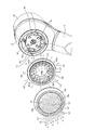
以下、本実施形態に係るシャワーヘッドについて、図面を参照しながら説明する。図1は、浴室10の壁11に配設されたシャワー設備12の構成を示す説明図である。
シャワー設備12は、所謂壁掛け型のシャワー設備であり、湯水を供給するホース13と、同ホース13の先端に取り付けられた本実施形態に係るシャワーヘッドAとを備えており、使用者Uが図示しない水栓を操作することで、シャワーヘッドAより通常の湯水や電解湯水を吐水可能としている。
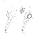
シャワーヘッドAは、図2(a)に示すように、ホース13を介して供給される湯水を吐出するシャワー本体15と、電力を蓄える蓄電体16とを備え、これらは外観上略一体的に形成されている。
またシャワーヘッドAには、図2(b)に示すように、ヘッド部18の側面周回りに沿って報知部9を形成している。このリング状に形成した報知部9は、前述のヘッド側面発光による状態報知機能を実現するための部位であり、報知部9から発せられる光によりシャワーヘッドAの状態情報を報知可能としている。
また、蓄電体16はシャワー本体15に対し、後述する係着機構を介して着脱自在に構成しており、蓄電体16への充電時や、電解することなく通常の湯水を吐出させる場合(以下、電解不要時と称する。)には、シャワー本体15から蓄電体16を取り外しできるようにしている。
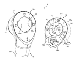
シャワー本体15は図3に示すように、使用者Uが把持するステム部17と、ステム部17の先端に配されたヘッド部18とを備え、同ヘッド部18の一面側(図3において紙面奥側)に散水板19を配して吐水可能とすると共に、散水板19と対向するヘッド部18の背面18a側、すなわち、図3において紙面手前側に、蓄電体16を装着するための装着部20を形成している。
また、この装着部20は、本実施形態では係着機構として所謂バイオネットロック機構のオス型又はメス型のいずれか一方の構造(本実施形態ではメス型構造)としており、蓄電体16の底面16aに形成されたバイオネットロック機構のいずれか他方の構造(本実施形態では、オス側構造)を有する係着部21を嵌着し所定方向へ回転させることで蓄電体16をシャワー本体15に係止可能としている。
また、蓄電体16がシャワー本体15に装着された状態で蓄電体16を回転させ、装着部20から係着部21を離脱させることにより、蓄電体16を容易に取り外し可能としている。
このように、蓄電体16の装着位置を、ヘッド部18の散水板19と対向する反対側の位置としたことにより、蓄電体16の重量をバランサーとして機能させて吐水時の反作用を軽減し、使用時のハンドリング性を向上させることができる。
また、係着部21には蓄電体16の電力をシャワー本体15へ供給するための給電端子80として、送電側陽極端子80aと送電側陰極端子80bとが備えられている。この送電側陽極端子80a及び送電側陰極端子80bは、蓄電体16をヘッド部18の背面18aに装着した際に装着部20に配設した受電側陽極端子20aと受電側陰極端子20bとにそれぞれ接触することで、電力を供給する。
また、蓄電体16の底面16aには、係着部21の他に、充電端子16bが配設されている。この充電端子16bは、蓄電体16に蓄電するための端子であり、シャワーヘッドAの使用時には充電端子16bが露出しないよう保護キャップ16dが嵌着される。
ここで、ヘッド部18に対する蓄電体16の装着に関し、本実施形態に係るシャワーヘッドの特徴の一つについて言及すると、図3に示すように、係着面である蓄電体16の底面16a上において、陽極端子である送電側陽極端子80aと陰極端子である送電側陰極端子80bとを結ぶ仮想直線M1を横断するように、凹部81を形成している点が挙げられる。
図4は、蓄電体16をヘッド部18に装着した状態での仮想直線M1に沿った要部断面を示す説明図である。蓄電体16をヘッド部18の背面18aへ装着すると、図4に示すように、底面16aと背面18aとの間には、幅d1の僅かな隙間が形成される。このような僅かな隙間は、電解水シャワーの使用時に毛細管現象が生起されて給電端子80の浸水、例えば受電側陽極端子20aと送電側陽極端子80aとの接点近傍において水W1による浸水が発生し、両電極間を短絡させてしまう場合がある。
この際、仮想直線M1上を横断するように凹部81を設けると、図4に示すようにこの凹部81部分の背面18aと底面16aとの間隙は幅d1よりも大きな幅d2となる。従って、毛細管現象は弱められることとなり、水W1が受電側陰極端子20bや送電側陰極端子80bの接点近傍に至ることを効果的に防止して、シャワーヘッドの使用時に給電端子の陽極-陰極間の浸水による短絡を可及的に防止することができる。
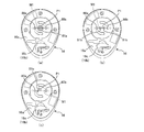
なお、図3及び図4において凹部81は、平面視円形状の領域としたが、これに限定されるものではなく、陽極端子と陰極端子とを結ぶ仮想直線を横断するように形成されるならばその形状は任意である。一例を挙げるならば、図5(a)に示すように、蓄電体16とヘッド部18との係着構造であるバイオネットロック構造の着脱回転軸P1を中心とする平面視ドーナツ状の凹部81aのように環状であっても良いし、図5(b)に示すように着脱回転軸P1を中心とする回転対照位置に形成した扇形の凹部81bのような領域とすることもできる。
また凹部81は、仮想直線M1を横断する位置に形成されていれば、着脱回転軸P1とは無関係であっても良く、例えば図5(c)に示すような位置に形成することもできる。
また本実施形態では、底面16a上における、陽極端子と陰極端子(送電側陽極端子80aと送電側陰極端子80b)を結ぶ仮想直線M1を横断する凹部81について例示して説明したが、これに限定されるものではなない。すなわち、ヘッド部18の背面18a上における陽極端子と陰極端子(受電側陽極端子20aと受電側陰極端子20b)を結ぶ仮想直線を横断する凹部を形成することによっても、同様に毛細管現象を部分的に抑制することができ、浸水による短絡を可及的に防止することができる。
また、本実施形態に係るシャワーヘッドAの係着部分における更なる特徴として、図3にも示したように、蓄電体16に蓄電するための充電端子16bと、蓄電体16に蓄えた電力をシャワー本体15へ供給する給電端子80(送電側陽極端子80aや送電側陰極端子80b)とを、いずれも蓄電体16の同じ面、すなわち蓄電体16の係着面21aに配設している点が挙げられる。
このような構成を備えることにより、電解を行うべく蓄電体16をヘッド部18に係着状態とした場合には、充電端子16bも同じ係着面21aに形成されているため充電を行うことができず、充電しながらのシャワーヘッドの使用による感電事故を未然に防止することができる。
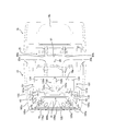
次に、シャワーヘッドAの各部構成について更に説明する。図6はシャワーヘッドAの構成を示した分解図であり、図7はシャワーヘッドAの内部構成を示した断面図、図8はヘッド部18及び蓄電体16の内部構成を示した断面説明図である。シャワーヘッドAは、図6に示すように、先述の通りシャワー本体15と蓄電体16とで構成され、また、シャワー本体15は、ステム部17とヘッド部18とを備えており、更にステム部17は、外筒体22と、電解部23とで構成している。
蓄電体16は、シャワー本体15にて電解を行ったり、使用者に対しシャワーヘッドAの各種状態について報知を行うために必要なエネルギーを供給するための電力を蓄えておく役割を有している。具体的には、蓄電体16の内部には、図7に示すように蓄電池16cが配設されており、同じく蓄電体16の内部に収容された蓄電体制御基板60a(蓄電体制御部60)を介して充電可能に構成している。なお、蓄電体16への充電は、シャワー本体15より取り外した蓄電体16を、図示しない充電台等に載置することで可能としている。
外筒体22は、図6中において上方へ拡開するテーパー筒状の部材であり、使用者が把持する把持部として機能する。また、次に述べる電解部23の外方を囲繞する外筒としての役割も有している。
また、外筒体22の下部には雄ネジ部22aが形成されており、所定の金具等を介してホース13と接続可能としている。
また、外筒体22の上部には雌ネジ部22bが形成されており、ヘッド部18の接続口18dの外周に形成された雄ネジ部18bと接続可能に構成している。
電解部23は、ホース13より供給された湯水をヘッド部18へ導くと共に、後述する本体側制御部70(本体側制御基板70a)の制御に応じて湯水を電気分解するための部材であり、図7において矢羽根の矢印で湯水の流れを示すように、外筒体22の内部に収容された内筒の流路として機能して、外筒体22と共に二重筒構造のステム部17を構成するものである。
図6に示すように、電解部23の下部には湯水の流入口23aが形成されている。この流入口23aは、外筒体22の内部で雄ネジ部22a近傍に形成された流入口接続口22c(図7参照)にパッキン23cを介して水密状に嵌着され、ホース13より供給される湯水を電解部23内へ導く。
また、図6に示すように、電解部23の上部には、湯水の流出口23bが形成されている。この流出口23bは、図7に示すヘッド部18の接続口18dの内方に形成されている流出口接続口18cに水密状に嵌着され、電解部23より流出する湯水、すなわち、電解時には電解湯水が、電解不要時には通常の湯水が電解部23からヘッド部18内へ導入される。
また、図6に示すように、電解部23の上部には、陽極端子23d及び陰極端子23eが配設されている。陽極端子23d及び陰極端子23eは、図7に示すように、電解部23の内部に配設された陽極板25及び陰極板26とそれぞれ電気的に接続したターミナルであり、陽極端子23d及び陰極端子23eは、ヘッド部18内に収容されている本体側制御部70と図示しない給電ケーブルを介して接続されている。
陽極板25及び陰極板26は、電解部23の内部にて湯水を電解するための電解電極板としての役割を担うものであり、陽極板25は陽極端子23dと電気的に接続されて相対的に陽極となり、陰極板26は陰極端子23eと電気的に接続されて相対的に陰極となって電解部23内で流水に対し電解を行う。
また、これら陽極板25や陰極板26は、電解部23の内部において、3枚の陰極板26の間にそれぞれ1枚ずつ陽極板25を配し、合計5枚の電極板が間隙を介して層状に重畳する構造を有した積層電極体を構成している。
また、この積層電極体の極間の間隙は0.3~1.0mmとしており、電解効率に優れた狭隘電極体を構成している。なお、各電極板は、例えば板厚が0.1mm~1.0mm、より好ましくは0.2mm~0.5mmとすることができ、材質としては、例えば、白金をメッキしたチタン板などを用いることができる。
ヘッド部18は、図6~図8に示すように、電解部23を通じて流出口接続口18cより流入する湯水を散水板19から吐水させるための部材であり、その内部は図7~図9に示すように仕切壁として機能する後壁41によって湯水の流路となる浸水領域と非浸水性の領域とに区画されている。
また、図9に示すように、後壁41には、光源部101と、流水検知部102とが備えられている。光源部101は流路領域側へ光を出射するための部位であり、図8に示すように本体側制御基板70a上に配したLED134と、同LED134の実装位置に対応して配設した筒状の光出射筒121bと、同光出射筒121bの浸水領域側開口を水密状に閉蓋する透明素材で形成した光源キャップ135とで構成している。なお、本明細書において光源はLED134自体ではなく、当該光源部101を意味する。
また、本実施形態においてLED134はフルカラーLEDを採用しており、本体側制御基板70a上に構築された本体側制御部70の制御により報知すべき状態情報に応じて色を変化可能としている。LED134からの光は、光出射筒121bを通じ光源キャップ135を透光し、図9において矢印で示すように浸水領域側である水室42内の貯留された湯水へ、特に後述の導光体105と散水板19へ指向させて出射光L1として出射される。
また、水室42内の貯留された湯水へ出射された出射光L1は、図8に示すように、後述する導光体105の筒状部105aと拡開部105bとの間に形成された環状鋭角溝形状の湯水-光作用空間43において、光に対し水室42内を流れる湯水によって揺らぎが付与される。
また特に、電解部23にて電解に供された上で光作用空間43(水室42)内へ流入する湯水(電解水)には、電解により生じた水素等の肉眼で見える程度の気泡や、白濁状に視認される極めて微細な気泡など、大小様々な気泡が含まれている。
これらの気泡は、シャワーヘッドAへの水道設備からの給水圧や量、温度や使用者のシャワーヘッドAの傾け具合などによって複雑に変化する水室42内での水流と相俟って、出射光L1と相互的に作用し合い、揺らぎをより顕著な状態とする。
そして、湯水による揺らぎの作用を受けた出射光L1は、例えば符号L1aで示すように導光体105の筒状部105aに入射したり、符号L1bで示すように拡開部105bへ入射したり、更には符号L1cで示すように通水孔105dを通り抜け導光体105に入射することなく散水板19へ至ることとなる。
従って、LED134などのような比較的指向性の高い発光体から発せられた光を湯水の揺らぎにより屈折させ、出射光L1(L1a~L1cも含む)の進行方向を経時的に変化させることで偏りの少ない照射、より具体的には後述の散乱光L2や散乱光L4の発生を実現している。
また、出射光L1と気泡との作用は、光に湯水の水流による揺らぎをより顕著に反映させるため、湯水の流れに関する状態情報の色や点灯パターンによる報知が無くとも、光の揺らぎ自体によって水室42内に流水が存在することを報知することもできる。
図9に示す流水検知部102は、浸水領域の水の流れを水圧によって検知するための部位であり、図8に示すように、後壁41の中央に配設したダイヤフラム部102aと、ダイヤフラム部102aと対応する本体側制御基板70a上に実装したスイッチ102bとを備え、ダイヤフラムスイッチを構成している。
ダイヤフラム部102aは、浸水領域内の水の流れに伴う圧力に応じて感圧移動体102cを移動させる機能を有しており、流水が無く浸水領域内圧力が低い場合、感圧移動体102cは弾性体102dによって浸水領域側に付勢されているが、流水があり浸水領域内圧力が高まると、感圧移動体102cは弾性体102dの弾性力に抗して非浸水性領域側へ移動させられスイッチ102bを押下する。後述する本体側制御部70は、このスイッチ102bのON又はOFFの状態を流水の有無に関する情報として取り扱う。
特に、本実施形態に係るシャワーヘッドAでは、この流水検知部102のダイヤフラム部102aを水室42の散水板19と対向する後壁41に設けているため、湯水の流路中で最も流路抵抗が大きな散水板によって高められた水室42の内圧を鋭敏に捕捉することができ、精度良く流水の有無を検知可能としている。
浸水領域は、後壁41で仕切られることにより区画形成された湯水が流れる浸水性の領域であり、図7に示すように、流出口接続口18cと、水室42とより構成している。流出口接続口18cはヘッド部18内に流入した湯水を水室42に導くための流路であり、電解部23の流出口23bとの連通連結部分は、流出口23bの外形と略同径の内径とすると共に、パッキン23f(図6参照)と密着させて水密性が保たれるよう構成している。
水室42は、流出口接続口18cより流入した湯水を一定量蓄水してその水流を緩衝するための部位である。この水室42は略円柱状の空間としており、その底面に相当する部位に微孔19aが複数形成された散水板19を設け、湯水を散水可能としている。付言すれば、前述の後壁41は、この散水板19と対向して設けられている。
また、水室42の内部には、図7~図9に示すように、導光体105を配設している。導光体105はやや乳白色を有する透明乃至半透明の樹脂にて形成した部材であり、光源部101からの出射光L1を入射させ、導光しつつも散乱光を放射できる性状を備えている。
図8や図9に示すように導光体105は、筒状部105aと、筒状部105aの内方へ向けて形成した拡開部105bと、筒状部105aの周回り中途に形成したリング部105cとを備えている。
筒状部105aは、水室42の内部にて導光体105がぴったりと収まるよう躯体としての役割を有する部位であり、また、光源部101より出射された出射光L1、特に先述の光作用空間43において湯水の流れによる揺らぎ作用を受けた光L1aを入射させて導光体105内に取り込むための部位でもある。
拡開部105bは、筒状部105aの散水板19側周端部から内方へ向けてすり鉢状に形成した複数の通水孔105dを備える部位であり、図8及び図9に示すように、光源部101より出射された出射光L1(光L1b)を受光して導光体105内へ取り込むと共に、導光体105内に入射した光を散水板19側に導びき、散乱光L2を生じさせて放射するための部位である。この拡開部105bから出射された散乱光L2は、主に散水板19の内面側を照らす。
また先述の如く導光体105は、筒状部105aと拡開部105bにより環状鋭角溝を形成しており、水室42内に装着された際に湯水-光作用空間43を形成することで、出射光L1と湯水との相互作用の促進と、湯水の揺らぎが付与された出射光L1の導光体105への効率的な入射とを実現している。
散水板19には多数の微孔19aが形成されており、この微孔19aを通じることで湯水が散水されることとなるのであるが、本実施形態に係るシャワーヘッドAでは、図9に示すように、出射光L1(特にL1c)や散乱光L2をこの微孔19aを介し漏出させて散水光L3として出射し、同じ微孔19aから吐出される湯水に対し散水光L3を照射するよう構成している。
従って、散水板19からの散水自体が光ファイバの如き透光部材として機能し、あたかも散水自ら発光しているかのように演出しつつ、散水発光による状態報知機能を実現することができる。また、出射光L1と散乱光L2との双方を微孔19aから出射させているため、満遍なく広がる柔らかな散乱光L2をベースとしながらも、導光体105を介さず相対的に強い光の出射光L1により湯水による顕著な揺らぎを使用者Uに視認させることができる。
また、散水板19の水室42側の面、すなわち、後壁41に配設された光源部101と対向する面は金属光沢を有しており、微孔19aに至らず散水板19の本体に至った光を水室42内へ再び反射するよう構成している。
このような構成を備えることにより、更なる乱反射や流水の揺らぎによって微孔からの出射を促すことができる。また、導光体105への再入射を促すことができる。
リング部105cは、導光体105内に入射した出射光L1(例えば、L1aやL1b)をヘッド部18の側面側に導いて、散乱光L4を出射させるための部位である。すなわち、リング部105cは、シャワーヘッドAのヘッド側面発光による状態報知機能を実現するためにヘッド部18の側面部に配設された報知部9を構成する。
また、図7に示すように後壁41を隔てた非浸水領域には、本体側制御部70を配設している。
本体側制御部70には、先述の如く流水検知部102のスイッチ102bが配設されており、流出口接続口18cから水室42へ流入する水の流れを検出するためのセンサとして機能するよう構成している。
また、本体側制御部70には、電解部23の陽極端子23d及び陰極端子23eが図示しない接続ケーブルを介して接続されている。
次に、シャワーヘッドAの電気的構成について説明する。図10は、蓄電体16及びヘッド部18の電気的構成を示したブロック図である。
まず、図10(a)には、蓄電体16の電気的構成についてのブロック図を示している。蓄電体16内の蓄電体制御基板60a上に構築される蓄電体制御部60は、CPU61やROM62、RAM63等を備えており、内蔵されたプログラム等を実行することで、充電や給電の開始・停止等を制御可能としている。
また、蓄電体制御部60には、給電制御回路64や充電制御回路65が備えられている。
給電制御回路64は、CPU61の指示により蓄電池16cに蓄えられている電力の給電端子80を介しての供給を制御するための回路である。
また充電制御回路65は、蓄電体16の充電を行う際、電力を蓄電池16cに蓄えるにあたり、電流や電圧を調整したり、過充電の防止を行うための回路である。
一方、ヘッド部18内の本体側制御基板70a上に構築された本体側制御部70は、図10(b)に示すように、CPU71やROM72、RAM73等を備えており、内蔵されたプログラム等を実行することで、使用者Uに対する光による報知や、流水検知部102のスイッチ102bの監視、陽極端子23d及び陰極端子23eへの電力供給の制御を可能としている。例えばRAM73には、蓄電体状態電圧値テーブルやエラーフラグが記憶される。
蓄電体状態電圧値テーブルは、満充電状態や通常状態、要充電状態などのような蓄電体16の各状態が蓄電体16の電圧と対応付けされたテーブルであり、蓄電体16の状態を判断するにあたり電圧値の測定が行われた際に参照される。
エラーフラグは、例えば蓄電体16の電圧が想定外の電圧状態である場合や、内部動作のテスト処理を実行した際に不具合が発見された場合などにON状態となるフラグである。
また、本体側制御部70には電解電流生成回路74が備えられている。電解電流生成回路74は、CPU71の指示により陽極端子23d及び陰極端子23e間の定電流の供給・遮断を行うための回路である。
また、本体側制御部70にはLEDドライブ回路75が備えられている。LEDドライブ回路75は、CPU71の指示によりLED134を所定の色及び点灯や点滅など所定の発光態様で発光させるための回路である。
次に、蓄電体16の制御部60において実行される蓄電体制御処理について、図11を参照しつつ説明する。蓄電体制御処理においてCPU61は、充電端子16bへの電力の入力を確認し、電力の供給があるか否かについて判断を行う(ステップS10)。ここで充電端子16bに電力の供給があると判断した場合(ステップS10:Yes)には、CPU61は、処理をステップS11へ移す。一方、充電端子16bに電力の供給はないと判断した場合(ステップS10:No)には、CPU61は処理をステップS10へ戻す。
ステップS11においてCPU61は、蓄電池16cの電圧を測定し、満充電であるか否かについて判断を行う。ここで満充電であると判断した場合(ステップS11:Yes)には、CPU61は充電制御回路65に対して充電停止を指示し(ステップS12)、処理を再びステップS10へ戻す。
一方、満充電ではないと判断した場合(ステップS11:No)には、CPU61は充電制御回路65に対し、適切な電圧や電流にて蓄電池16cの充電を行うよう指示し(ステップS13)、処理をステップS10へ戻す。
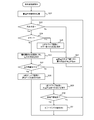
次に、シャワー本体15の本体側制御部70において実行される本体側制御処理について、図12を参照しつつ説明する。本体側制御処理において本体側制御部70のCPU71は、蓄電体状態報知処理を行う(ステップS21)。
この蓄電体状態報知処理は、シャワー本体15に通電が行われてすぐに実行される処理である。すなわち、シャワー本体15に蓄電体16が装着された際に、このステップS21が実行されて、使用者Uに対し光による状態情報の報知の一態様として、蓄電体16の状態に関する情報の報知が行われる。
具体的には、本ステップS21においてCPU71は、蓄電体16の装着により受電側陽極端子20aと受電側陰極端子20bとの間に印加された電圧を測定し、RAM73の所定アドレスに予め記憶された蓄電体状態電圧値テーブルを参照して、通常状態であるか、充電不足状態であるか等について判断を行う。
そしてCPU71は、例えば蓄電体16が通常状態であると判断した場合には、LEDドライブ回路75に対し青色点滅を指示し、充電不足状態であると判断した場合には橙色点滅を指示することで蓄電体状態に関する情報を報知する。
この蓄電体状態報知処理を終えると、CPU71は次に、流水検知部102のスイッチ102bの状態を参照し、流水状態であるか否かについて判断を行う(ステップS22)。ここで流水状態ではないと判断した場合(ステップS22:No)には、CPU71は処理をステップS23へ移す。
ステップS23においてCPU71は、電解電流生成回路74に対し、電流供給の停止を指示し、処理をステップS22へ戻す。
一方、流水状態であると判断した場合(ステップS22:Yes)には、CPU71は処理をステップS24へ移す。
ステップS24においてCPU71は、RAM73の所定アドレスに記憶されているエラーフラグの値を参照し、エラー状態であるか否かについて判断を行う。
ここでエラー状態であると判断した場合(ステップS24:Yes)には、CPU71は、LEDドライブ回路75に対し、LED134をエラー色(例えば、赤色)にて点滅するよう指示を行い(ステップS25)、処理をステップS23へ移す。
一方、エラー状態ではないと判断した場合(ステップS24:No)には、CPU71処理をステップS26へ移す。
ステップS26においてCPU71は、電解電流生成回路74に対し、電力の供給を指示する。より具体的には、電解部23等への電力の供給を開始し、湯水の電解を行う。
次にCPU71は、受電側陽極端子20aと受電側陰極端子20bとの間に印加された電圧の値や、RAM73で記憶している蓄電体状態電圧値テーブルを参照し、蓄電体16の電力残量が電解や報知を行うのに十分であるか否かについて判断を行う(ステップS27)。ここで電力残量が十分であると判断した場合(ステップS27:Yes)には、CPU71は、LEDドライブ回路75に対しして通常色(例えば、青色)での点灯を指示し(ステップS28)、処理をステップS22へ戻す。
一方、電力残量が十分ではないと判断した場合(ステップS27:No)には、CPU71はLEDドライブ回路75に対し充電不足色(例えば橙色)での点灯を指示し(ステップS29)、処理をステップS30へ移す。なお、本ステップS29や前述のステップS28は、蓄電体16の状態に関する情報が行われているのは勿論のこと、ステップS22においてシャワー本体15の流路内に湯水が流れているときにステップS28やステップS29が実行されるようにしていることから、湯水の状態、すなわち湯水が流れているか否かについての情報を光により報知するステップであると言える。
ステップS30においてCPU71は、受電側陽極端子20a及び受電側陰極端子20bにおける電圧の値が、予め規定した放電下限電圧の値に達したか否かについて判断を行う。ここで、電圧の値が放電下限電圧に達していないと判断した場合(ステップS30:No)には、CPU71は処理をステップS22へ戻す。一方、電圧の値が放電下限電圧に達していると判断した場合(ステップS30:Yes)には、CPU71は、電圧の異常状態であるとしてRAM73エラーフラグの値をONとし(ステップS31)、処理をステップS22へ戻す。
そして、上述してきた構成を備えるシャワーヘッドAによれば、図9にて示したように、光源部101より出射した出射光L1を湯水-光作用空間43にて湯水の流れと作用させ、図8にて示した光L1aや光L1bの如く導光体105にて受け、散乱光L2として散水板19へ向け更に出射したり、光L1cの如く直接散水板19に至るなどして微孔19aを介し散水と共に散水光L3が出射されるよう構成している。
従って、蓄電体16をシャワー本体15に装着した直後や、シャワーヘッドAの使用中(電解水の吐水中)において、例えば蓄電体16の電力残量に関する情報や、湯水の状態に関する情報などの状態情報を、図13にて符号Bで示すように、散水を介して光により使用者等に対し報知することができ、光によって入浴時のリラックスした雰囲気を醸す演出効果が得られるのは勿論のこと、シャワーヘッドAの状態について使用者Uやその周囲の者に堅実に報知し認識させることができる。特に、湯水-光作用空間43にて湯水を透過させた出射光L1により情報を報知することとしたため、湯水の水流による揺らぎにより光の進行方向を経時的に変化させて偏りの少ない光による報知を実現することができる。
また、同じく図9にて示したように、光源部101より出射された出射光L1は、報知部9を構成する導光体105のリング部105cより散乱光L4として出射される。
従って、図13にて符号Cで示すように、蓄電体16の装着直後や、電解水の吐水中において状態情報を、ヘッド部18の側面に配した報知部9より光によって使用者等に報知することができ、光によって入浴時のリラックスした雰囲気を醸す演出効果が得られるのは勿論のこと、シャワーヘッドAの状態について使用者Uやその周囲の者に堅実に報知し認識させることができる。
最後に、上述した各実施の形態の説明は本発明の一例であり、本発明は上述の実施の形態に限定されることはない。このため、上述した各実施の形態以外であっても、本発明に係る技術的思想を逸脱しない範囲であれば、設計等に応じて種々の変更が可能であることは勿論である。
9 報知部
16 蓄電体
16a 底面
16b 充電端子
18 ヘッド部
18a 背面
19 散水板
20 装着部
20a 受電側陽極端子
20b 受電側陰極端子
21a 係着面
23 電解部
41 後壁
42 水室
43 湯水-光作用空間
60 蓄電体制御部
70 本体側制御部
80 給電端子
80a 送電側陽極端子
80b 送電側陰極端子
81 凹部
101 光源部
102 流水検知部
102b スイッチ
A シャワーヘッド
L1 出射光
L3 散水光
L4 散乱光
M1 仮想直線
16 蓄電体
16a 底面
16b 充電端子
18 ヘッド部
18a 背面
19 散水板
20 装着部
20a 受電側陽極端子
20b 受電側陰極端子
21a 係着面
23 電解部
41 後壁
42 水室
43 湯水-光作用空間
60 蓄電体制御部
70 本体側制御部
80 給電端子
80a 送電側陽極端子
80b 送電側陰極端子
81 凹部
101 光源部
102 流水検知部
102b スイッチ
A シャワーヘッド
L1 出射光
L3 散水光
L4 散乱光
M1 仮想直線
Claims (12)
- 蓄電体に蓄えた電力を流路の中途に配した電極体へ供給し、前記流路を流れる湯水を電気分解してヘッド部より散水するシャワーヘッドであって、
前記ヘッド部は散水前の湯水を貯留する水室を備え、同水室の開口に配設した散水板と対向する水室の後壁に前記蓄電体及び/又は前記湯水の状態に関する情報を含む光を出射する光源を設けると共に、同光源から水室へ向けて出射され湯水を透過した光により前記情報を報知すべく構成したことを特徴とするシャワーヘッド。 - 前記ヘッド部は、前記散水板の微孔から漏出した光により散水を介して前記情報を報知することを特徴とする請求項1に記載のシャワーヘッド。
- 前記水室内には、前記光源からの光を入射させ、導光しつつ散乱させる導光体が備えられていることを特徴とする請求項2に記載のシャワーヘッド。
- 前記微孔からの漏出光は、前記導光体にて生じた散乱光と前記導光体に形成された通水孔を通じて散水板に至った光との両方が微孔から漏出した光であることを特徴とする請求項3に記載のシャワーヘッド。
- 前記散水板の前記光源との対向面は金属光沢を有することを特徴とする請求項1~4いずれか1項に記載のシャワーヘッド。
- 前記ヘッド部の側面には、光により前記情報を報知する報知部が備えられていることを特徴とする請求項1に記載のシャワーヘッド。
- 前記水室内には、前記光源からの光を入射させ、導光しつつ散乱させる導光体が備えられており、前記報知部から出射する光は前記導光体内に入射して散乱した光であることを特徴とする請求項6に記載のシャワーヘッド。
- 前記蓄電体は前記ヘッド部の散水面と対向する背面に係着可能であり、蓄電体の係着面には、同蓄電体に蓄電するための充電端子と、蓄電体に蓄えた電力を前記電極体へ供給する給電端子とがそれぞれ配設されていることを特徴とする請求項1~7いずれか1項に記載のシャワーヘッド。
- 前記給電端子は、前記蓄電体の係着面上に設けた送電側陽極端子と送電側陰極端子とを備え、前記ヘッド部の背面上には、係着時に前記送電側陽極端子と送電側陰極端子とにそれぞれ接触する受電側陽極端子と受電側陰極端子とを設けると共に、
前記係着面上及び/又は背面上には、陽極端子と陰極端子とを結ぶ仮想直線を横断する凹部が形成されていることを特徴とする請求項8に記載のシャワーヘッド。 - 前記水室の後壁に前記湯水の流水を検知するダイヤフラムスイッチを配設したことを特徴とする請求項1~9いずれか1項に記載のシャワーヘッド。
- 蓄電体に蓄えた電力を流路の中途に配した電極体へ供給し、前記流路を流れる湯水を電気分解してヘッド部より散水するシャワーヘッドであって、
前記蓄電体は前記ヘッド部の散水面と対向する背面に係着可能であり、蓄電体の係着面には、同蓄電体に蓄電するための充電端子と、蓄電体に蓄えた電力を前記電極体へ供給する給電端子とがそれぞれ配設されていることを特徴とするシャワーヘッド。 - 前記給電端子は、前記蓄電体の係着面上に設けた送電側陽極端子と送電側陰極端子とを備え、前記ヘッド部の背面上には、係着時に前記送電側陽極端子と送電側陰極端子とにそれぞれ接触する受電側陽極端子と受電側陰極端子とを設けると共に、
前記係着面上及び/又は背面上には、陽極端子と陰極端子とを結ぶ仮想直線を横断する凹部が形成されていることを特徴とする請求項11に記載のシャワーヘッド。
Applications Claiming Priority (2)
| Application Number | Priority Date | Filing Date | Title |
|---|---|---|---|
| JP2018243629A JP7199962B2 (ja) | 2018-12-26 | 2018-12-26 | シャワーヘッド |
| JP2018-243629 | 2018-12-26 |
Publications (1)
| Publication Number | Publication Date |
|---|---|
| WO2020137073A1 true WO2020137073A1 (ja) | 2020-07-02 |
Family
ID=71126187
Family Applications (1)
| Application Number | Title | Priority Date | Filing Date |
|---|---|---|---|
| PCT/JP2019/039239 Ceased WO2020137073A1 (ja) | 2018-12-26 | 2019-10-04 | シャワーヘッド |
Country Status (2)
| Country | Link |
|---|---|
| JP (1) | JP7199962B2 (ja) |
| WO (1) | WO2020137073A1 (ja) |
Citations (4)
| Publication number | Priority date | Publication date | Assignee | Title |
|---|---|---|---|---|
| JPH0217253U (ja) * | 1988-07-21 | 1990-02-05 | ||
| JP2003174978A (ja) * | 2001-12-11 | 2003-06-24 | Osaka Gas Co Ltd | 浴用シャワー装置 |
| JP2017172260A (ja) * | 2016-03-25 | 2017-09-28 | Toto株式会社 | システムキッチン |
| JP2017217158A (ja) * | 2016-06-06 | 2017-12-14 | マクセルホールディングス株式会社 | 吐水設備構造及び同吐水設備構造を備えたシャワーヘッド、蛇口水道設備、打たせ湯設備 |
Family Cites Families (4)
| Publication number | Priority date | Publication date | Assignee | Title |
|---|---|---|---|---|
| KR200373768Y1 (ko) | 2004-10-21 | 2005-01-26 | 주식회사 건축사 사무소 도시건축 | 원적외선 샤워기를 갖춘 욕실의 건축용 급수구조 |
| KR100951139B1 (ko) * | 2008-05-19 | 2010-04-07 | 전북대학교산학협력단 | 수압 발전식 감성 샤워기 |
| JP3168285U (ja) | 2010-11-01 | 2011-06-09 | スミヨシ化成株式会社 | 給水設備のアラーム表示ランプ |
| US10945059B2 (en) | 2011-09-06 | 2021-03-09 | Kohler Co. | Shower assembly |
-
2018
- 2018-12-26 JP JP2018243629A patent/JP7199962B2/ja active Active
-
2019
- 2019-10-04 WO PCT/JP2019/039239 patent/WO2020137073A1/ja not_active Ceased
Patent Citations (4)
| Publication number | Priority date | Publication date | Assignee | Title |
|---|---|---|---|---|
| JPH0217253U (ja) * | 1988-07-21 | 1990-02-05 | ||
| JP2003174978A (ja) * | 2001-12-11 | 2003-06-24 | Osaka Gas Co Ltd | 浴用シャワー装置 |
| JP2017172260A (ja) * | 2016-03-25 | 2017-09-28 | Toto株式会社 | システムキッチン |
| JP2017217158A (ja) * | 2016-06-06 | 2017-12-14 | マクセルホールディングス株式会社 | 吐水設備構造及び同吐水設備構造を備えたシャワーヘッド、蛇口水道設備、打たせ湯設備 |
Also Published As
| Publication number | Publication date |
|---|---|
| JP2020103455A (ja) | 2020-07-09 |
| JP7199962B2 (ja) | 2023-01-06 |
Similar Documents
| Publication | Publication Date | Title |
|---|---|---|
| US10456793B2 (en) | Cartridges and dispenser devices for jets of water incorporating such cartridges | |
| JP3143899U (ja) | ターボチャージャー機構を備えたシャワーヘッド | |
| CA2626660C (en) | Lighting unit for water fountains, ponds or the like | |
| JP6249200B1 (ja) | 電解セル及びそれを用いたオゾン水噴出装置 | |
| US11313143B2 (en) | Water spraying device and pool | |
| JP7202764B1 (ja) | 給水ユニット | |
| JP7082903B2 (ja) | シャワーヘッド | |
| US7794095B2 (en) | Sanitary fitting with a lightguide outflow pipe | |
| AU2002305792A1 (en) | Sprayer and filter therefor | |
| US20070220670A1 (en) | Hand Shower | |
| CN111389610A (zh) | 一种喷液装置 | |
| JP7199962B2 (ja) | シャワーヘッド | |
| KR100951139B1 (ko) | 수압 발전식 감성 샤워기 | |
| JP7130570B2 (ja) | シャワーヘッド | |
| CN101438010B (zh) | 具有手持喷水装置以及充电单元的卫生系统 | |
| EP3268546B1 (en) | Water plug with cartridge | |
| JP7645505B2 (ja) | オゾン水散布装置 | |
| JP7465054B2 (ja) | 水素水生成装置 | |
| KR20110064750A (ko) | 발전과 수온표시 및 버블 발생을 위한 다기능 수도 장치 | |
| KR200373768Y1 (ko) | 원적외선 샤워기를 갖춘 욕실의 건축용 급수구조 | |
| CN221958297U (zh) | 一种发光出水装置及抽拉龙头 | |
| JP3245886U (ja) | オゾン水噴出装置 | |
| KR102148764B1 (ko) | 구강 세정 장치 | |
| JP2019166502A (ja) | 水素水生成装置 | |
| US20240140834A1 (en) | Dual faucet with sterile water and regular water supply function |
Legal Events
| Date | Code | Title | Description |
|---|---|---|---|
| 121 | Ep: the epo has been informed by wipo that ep was designated in this application |
Ref document number: 19903511 Country of ref document: EP Kind code of ref document: A1 |
|
| NENP | Non-entry into the national phase |
Ref country code: DE |
|
| 122 | Ep: pct application non-entry in european phase |
Ref document number: 19903511 Country of ref document: EP Kind code of ref document: A1 |