WO2020136779A1 - 面ファスナー - Google Patents
面ファスナー Download PDFInfo
- Publication number
- WO2020136779A1 WO2020136779A1 PCT/JP2018/047982 JP2018047982W WO2020136779A1 WO 2020136779 A1 WO2020136779 A1 WO 2020136779A1 JP 2018047982 W JP2018047982 W JP 2018047982W WO 2020136779 A1 WO2020136779 A1 WO 2020136779A1
- Authority
- WO
- WIPO (PCT)
- Prior art keywords
- surface fastener
- segments
- segment
- engaging
- engaging portions
- Prior art date
- Legal status (The legal status is an assumption and is not a legal conclusion. Google has not performed a legal analysis and makes no representation as to the accuracy of the status listed.)
- Ceased
Links
Images




Classifications
-
- A—HUMAN NECESSITIES
- A44—HABERDASHERY; JEWELLERY
- A44B—BUTTONS, PINS, BUCKLES, SLIDE FASTENERS, OR THE LIKE
- A44B18/00—Fasteners of the touch-and-close type; Making such fasteners
Definitions
- the present invention relates to a surface fastener.
- Velcro fasteners are typically used in clothing, bags, shoes, and sundries as opening and closing tools.
- the surface fastener is composed of a pair of surface fastener members that engage with each other, and the surface fastener member includes a substrate and a large number of engaging elements protruding from one surface of the substrate that are integrally molded. There are various reports on surface fasteners in which these surface fastener members are engaged with each other.
- a silent surface fastener including a first engagement body (10) and a second engagement body (20), wherein the first engagement body (10) is made of hard resin. Therefore, a large number of columnar protrusions (12) are integrally formed on the substrate (11), gaps (14) are formed between the protrusions (12), and the second engaging body (20) is made of a soft resin. And a columnar protrusion (22) is planted on the base cloth (21), and a gap (23) is formed between the protrusions (22). 22) and a silent surface fastener in which the above-mentioned gaps (14, 23) between the other engaging bodies are fitted to each other have been proposed.
- the hook is provided with a plurality of cylindrical protrusions (42) made of synthetic resin on the surface side of a relatively hard surface fastener cloth (41) or a synthetic resin sheet.
- the female and male surface fastener tapes have the same shape, and the hollow (43) in which the cylindrical projection (42) of one tape (40) is surrounded by the cylindrical projection (42) of the other tape (40)
- a hook and loop fastener tape (40) has been proposed for engaging with.
- the article is It is considered to be difficult to apply to the curved part of the.
- the surface fastener tape described in Patent Document 2 has the relatively hard surface fastener cloth (41) or the synthetic resin sheet, even if it can be flexibly curved in one direction, the other direction It is believed that it cannot be bent.
- the conventional surface fastener is not easily applied to the curved portion of the article.
- the pair of surface fastener members may be disengaged. Therefore, it is considered that there is still room for improvement in the surface fastener in the related arts such as Patent Documents 1 and 2.
- an object of the present invention is to provide a surface fastener that can flexibly cope with a curved portion of an article. Another object is to provide a surface fastener that can flexibly deal with twisting of articles. Further, it is an object of the present invention to provide an article provided with such a surface fastener.
- a surface fastener comprising a first surface fastener member and a second surface fastener member that can be engaged and disengaged with each other
- the first surface fastener member includes a plurality of first segments and a connecting portion of a soft member that connects adjacent first segments
- the second surface fastener member includes at least one second segment
- Each of the first and second segments has a substrate, a plurality of engaging portions projecting from the substrate, and an engagement space defined between the plurality of engaging portions, The first segment and the second segment are engaged by receiving a part of at least one of the engaging portions of one of the first and second segments into the other engaging space.
- a hook-and-loop fastener that fits.
- the first surface fastener member is capable of receiving a part of the engaging portions of the plurality of engaging portions of the second surface fastener member in an engageable and disengageable manner between the adjacent first segments.
- the substrate of the first and second segments has a recess or an opening at a position corresponding to the engagement space, and the first and second segments are in a state in which the first and second segments are engaged.
- the substrate of the first and second segments further has a recess or an opening outside the engagement portion group consisting of the plurality of engagement portions and at a position corresponding to the other engagement portion, In a state where the first and second segments are engaged, at least one engaging portion of the plurality of engaging portions of the first and second segments has a part of the concave portion of the second and first segments.
- a surface fastener that can flexibly cope with a curved portion of an article and flexibly deal with twisting of the article.
- FIG. 2(A) is a schematic plan view of a surface fastener member in an embodiment of the surface fastener according to the present invention
- FIG. 2(B) is a view taken along the line CC of FIG. 2(A)
- FIG. 3A is a partial sectional view taken along the line AA of FIG. 1, and FIG. 3B is a modification of FIG. 3A.
- FIG. 3 is a schematic plan view showing the surface fastener member in a state where the connecting portion of the surface fastener member is curved in the embodiment of the surface fastener according to the present invention.
- FIG. 2 is a partial front view taken along the line BB of FIG. FIG.
- FIG. 3 is a partially enlarged view for explaining an engaged state of the first segment and the second segment in the embodiment of the surface fastener according to the present invention. It is a typical perspective view of another embodiment of a surface fastener concerning the present invention.
- FIG. 8(A) is a schematic plan view of a surface fastener member in another embodiment of the surface fastener according to the present invention, and FIG. 8(B) is a line DD in FIG. 8(A).
- FIG. FIG. 9(A) is a schematic plan view of a surface fastener member in another embodiment of the surface fastener according to the present invention, and FIG. 9(B) is a line EE arrow of FIG. 9(A).
- FIG. It is the figure described in patent document 1 (FIG. 1). It is the figure described in patent document 2 (FIG. 7).
- the present invention is not limited to the embodiments described below, and has various modifications as long as it has substantially the same configuration as the present invention and has the same effects. It is possible. Further, although the segments are arranged in a line in the vertical direction in the embodiment described later, a plurality of segments may be arranged vertically and a plurality of segments may be arranged horizontally. Further, regarding the number of the engaging portions of the segment, in the embodiment described later, a surface fastener member having three engaging portions vertically, three horizontally and four vertically, and four horizontally is mentioned. It suffices that a plurality of sections are arranged vertically and a plurality of sections are arranged horizontally.
- the “up and down direction” defines the front and back direction of the board as the up and down direction, and particularly refers to the direction of the side where the engaging portion projects with respect to the board in the first surface fastener member described later. Upward, and the opposite direction is downward.
- the “horizontal direction” is a direction parallel to the main surface of the substrate of the segment and a direction perpendicular to the direction connecting the segments.
- the “front-back direction” is a direction parallel to the main surface of the substrate of the segment and a direction connecting the segments.
- FIG. 1 is a schematic perspective view of an embodiment of a surface fastener according to the present invention.
- FIG. 2(A) is a schematic plan view of a surface fastener member in an embodiment of the surface fastener according to the present invention
- FIG. 2(B) is a view taken along the line CC of FIG. 2(A).
- FIG. 3A is a partial cross-sectional view taken along the line AA of FIG. 1, and FIG. 4B is a modification of FIG. 4A.
- FIG. 4 is a schematic plan view showing the surface fastener member in a state where the connecting portion of the surface fastener member is curved in the embodiment of the surface fastener according to the present invention.
- FIG. 5 is a partial front view taken along the line BB of FIG.
- FIG. 6 is a partially enlarged view for explaining the engagement state of the first segment and the second segment in the embodiment of the surface fastener according to the present invention.
- the surface fastener (100) includes a first surface fastener member (110) and a second surface fastener member (150) that can be engaged and disengaged with each other.
- the first surface fastener member (110) is a connection that connects a plurality of first segments (120, 130, 140) and adjacent first segments (120, 130, 140). Parts (125, 135).
- the second surface fastener member (150) includes at least one second segment (160, 170, 180) for engaging the first surface fastener member (110) and the second surface fastener member (150). It is not particularly limited as long as it is provided, but may have the same structure as the first surface fastener member (110). More specifically, the second surface fastener member (150) includes a plurality of second segments (160, 170, 180) and connecting portions (165, 175) that connect adjacent second segments (160, 170, 180). With.
- Each of the first and second segments (120, 130, 140, 160, 170, 180) includes a substrate (121, 131, 141, 161, 171, 181) and a substrate (121, 131, 141, 161, 171, 171). 181) protruding from the plurality of engaging portions (122, 132, 142, 162, 172, 182) and engagement defined between the plurality of engaging portions (122, 132, 142, 162, 172, 182). And spaces (123, 133, 143, 163, 173, 183).
- the material of the first and second segments (120, 130, 140, 160, 170, 180) is preferably a soft resin from the viewpoint of intended use.
- the material of the first and second segments (120, 130, 140, 160, 170, 180) is the connecting portion from the viewpoint of molding the first and second surface fastener members (110, 150) with a molding machine. It may be the same as (125, 135, 165, 175).
- a large number of engaging portions (122, 132, 142, 162, 172, 182) project from a large number of places on one main surface of the substrate (121, 131, 141, 161, 171, 181).
- the large number of engaging portions (122, 132, 142, 162, 172, 182) are regularly arranged.
- the engaging portions (122, 132, 142, 162, 172, 182) of the first and second segments (120, 130, 140, 160, 170, 180) are as shown in FIG. 2(A).
- the first and second segments (120, 130, 140, 160, 170, 180) have three vertical and three horizontal arrays arranged at right angles, but the present invention is not limited to this and, for example, vertical and horizontal.
- the intervals in the directions may be arranged at an angle of 45°.
- the engaging portion (122, 132, 142, 162, 172, 182) includes a columnar stem (122a, 132a, 142a, 162a, 172a, 182a) and a stem (122a).
- 132a, 142a, 162a, 172a, 182a and has elliptical engagement heads (122b, 132b, 142b, 162b, 172b, 182b).
- the shape of the stems is not limited to a columnar shape, but a prismatic shape, a truncated cone shape, or an inverted truncated cone shape (see FIG. 3B). May be Further, the shape of the engaging head portions (122b, 132b, 142b, 162b, 172b, 182b) is not limited to the ellipsoidal shape, and is discoidal, hemispherical, or semielliptic (see FIG. 3B). ) Or the like.
- engaging heads are stems (122a, 132a, from the viewpoint of molding the first and second surface fastener members (110, 150) with a molding machine.
- 142a, 162a, 172a, 182a may be an integral structure.
- the diameter of the engaging head portion (122b, 132b, 142b, 162b, 172b, 182b) is larger than the diameter of the stem (122a, 132a, 142a, 162a, 172a, 182a). Accordingly, in one embodiment of the present invention, the number of engaging portions (122, 132, 142, 162, 172, 182) of the first and second segments (120, 130, 140, 160, 170, 180) is increased. A part of at least one of the engaging portions (122, 132, 142, 162, 172, 182) is part of the engaging space (123) of the second and first segments (120, 130, 140, 160, 170, 180).
- first and second segments 120, 130, 140, 160, 170, 180
- the proximal ends of the engaging heads (122b, 132b, 142b, 162b, 172b, 182b) of the first and second segments (120, 130, 140, 160, 170, 180) are different from other engaging heads. (122b, 132b, 142b, 162b, 172b, 182b) contacts the base end. As a result, the first segment (120, 130, 140) and the second segment (160, 170, 180) are not easily disengaged.
- the engagement spaces (123, 133, 143, 163, 173, 183) are in a state in which the first segment (120, 130, 140) and the second segment (160, 170, 180) are engaged, Two vertical and two horizontal engaging portions (122, 132, 142, 162, 172) corresponding to the engaging portions (122, 132, 142, 162, 172, 182) of the one segment, in the other segment. 182).
- the diameters of the engaging heads (122b, 132b, 142b, 162b, 172b, 182b) and the stems (122a, 132a, 142a, 162a, 172a, 182a) are so-called concentric circles.
- the tip of the engaging head (122b, 132b, 142b, 162b, 172b, 182b) has, for example, each segment (120, 130, 140, 160, 170, 180). It has a recessed concave portion from the viewpoint that it is easy to pull out from the mold when it is molded by a mold.
- the tip of the engaging head portion (122b, 132b, 142b, 162b, 172b, 182b) may not have a recessed recess.
- the engagement spaces (123, 133, 143, 163, 173, 183) are provided in the first and second segments (120, 130, 140, 160, 170, 180) with a large number of engagement portions (122, 132, 132). 142, 162, 172, 182), a part of at least one engaging portion (122, 132, 142, 162, 172, 182) is partially engaged with the other engaging space (123, 133, 143, 163, 173). 183) to engage the first segment (120, 130, 140) with the second segment (160, 170, 180).
- the center lines of the engagement spaces are located inside the engagement spaces (123, 133, 143, 163, 173, 183) in the engagement portions (122, 132, 142, 162, 172, 182) when received, they substantially coincide with the axes of the engaging heads (122b, 132b, 142b, 162b, 172b, 182b).
- the substrates (121, 131, 141, 161, 171, 181) of the first and second segments (120, 130, 140, 160, 170, 180) have engagement spaces ( 123, 133, 143, 163, 173, 183) has a concave portion or an opening portion.
- the recessed portion indicates a portion formed by denting one surface of the substrate, and the opening portion indicates a portion formed by penetrating the substrate.
- the substrates (121, 131, 141, 161, 171, 181) of the first and second segments (120, 130, 140, 160, 170, 180) have a large number of engaging portions (122, 132, 142, (162, 172, 182) outside the engagement portion group, and further has a recessed portion or an opening portion at a position corresponding to the other engagement portion (122, 132, 142, 162, 172, 182). As shown in FIG. 1, when the first segment (120, 130, 140) and the second segment (160, 170, 180) are in the engaged state, the first and second segments (120, 130).
- the surface fastener (100) has a structure in which lint, dust, etc. are unlikely to adhere.
- the first segment (120, 130, 140) and the second segment (160, 170, 180) only engage with each other as described above for the substrate in each segment.
- the first and second segments (120, 130, 140, 160, 170, 180) of the large number of engaging portions (122, 132, 142, 162, 172, 182) are less likely to attach lint or dust , Does not require regular maintenance to further maintain engagement force.
- the recesses or openings are regularly arranged.
- the engaging head of the first segment (120) As the first segment (120, 130, 140) and the second segment (160, 170, 180) are engaged, as shown in FIG. 3(A), the engaging head of the first segment (120) The tip end of (122b) contacts the side wall surface (161a) of the substrate (161) of the second segment (160). Engaging heads of the first and second segments (120, 130, 140, 160, 170, 180) when the first segment (120, 130, 140) is moved in the vertical direction, the horizontal direction, or the front-back direction.
- the proximal ends of the parts (122b, 132b, 142b, 162b, 172b, 182b) contact the proximal ends of the other engaging heads (122b, 132b, 142b, 162b, 172b, 182b), and further the first Friction occurs between the outer peripheral surface of the tip of the engaging head portion (122b) of the segment (120) and the side wall surface (161a) of the second segment (160).
- the engagement between the first segment (120, 130, 140) and the second segment (160, 170, 180) is not easily released.
- the surface fastener (100) is provided with the first and the second substrates (121, 131, 141, 161, 171, 181) even if the recess or opening as shown in FIG. 2(A) is not formed.
- the engaging portions (122, 132, 142, 162, 172, 182) of the second segment (120, 130, 140, 160, 170, 180) have corresponding first and second segments (120, 130, 140, 160, 170, 180) are accommodated in the engagement spaces (123, 133, 143, 163, 173, 183) of the first segment (120, 130, 140) and the second segment (160, 170, 180). And are engaged.
- the distance (H) between the recesses or openings reduces the bulkiness of the surface fastener (100), and from the viewpoint that the first and second surface fastener members (110, 150) are not disengaged due to external impact. It is smaller than the maximum diameter (R) of the head (122b, 132b, 142b, 162b, 172b, 182b) and is smaller than the diameter (r) of the tip of the engaging head (122b, 132b, 142b, 162b, 172b, 182b). large. Thereby, the engagement between the first segment (120, 130, 140) and the second segment (160, 170, 180) can be maintained.
- the distance (H) of the recess or opening is the shortest distance from the side wall surface (161a) in the recess or opening to the opposing side wall surface (161a).
- the engaging portion (122) has an inverted frustoconical stem (122a) whose diameter is increased in the upward direction and a semi-ellipsoidal tip of the stem (122a). It may consist of an engaging head (122b).
- the distance (H) of the recess or opening in the left-right direction is smaller than the maximum diameter (R) of the engaging head portions (122b, 132b, 142b, 162b, 172b, 182b).
- the connecting portions (125, 135, 165, 175) connect the first segments (120, 130, 140) adjacent to each other and connect the second segments (160, 170, 180). connect. Therefore, as shown in FIG. 4, the first surface fastener member (110) and the second surface fastener member (150) are curved at their connecting portions (125, 135, 165, 175) as starting points, so that It is possible to flexibly cope with the curved portion. Therefore, even if the first segment (120, 130, 140) and the second segment (160, 170, 180) are engaged with each other, the surface fastener (100) does not impair the function as the opening/closing tool.
- the multiple engaging portions (122, 132, 142, 162, 172, 182) and a part of at least one engaging portion (122, 132, 142, 162, 172, 182), and a part of the engaging space (123, 133, 143, 163, 173) of the other segment. 183).
- the first surface fastener member (110) reduces the bulkiness of the surface fastener (100), and allows the first and second surface fastener members (110, 150) to be attached freely.
- At least the engaging portion (162, 172) among the plurality of engaging portions (162, 172, 182) of the second surface fastener member (150) is provided between the adjacent first segments (120, 130, 140).
- 172, 182) has engaging spaces (123, 133, 143) capable of receiving a part of them in an engageable and disengageable manner.
- the second surface fastener member (150) has a plurality of engaging portions (122, 132, 142) of the first surface fastener member (150) between the adjacent second segments (160, 170, 180). It has an engagement space (163, 173, 183) capable of receiving at least a part of the engagement portion (122, 132, 142) in an engageable and disengageable manner.
- the separation distance (D) between the adjacent first segments (120, 130, 140) and between the second segments (160, 170, 180) reduces the bulkiness of the surface fastener (100), and allows the external fastener to be externally connected.
- the engagement head (122b is smaller than the maximum diameter (R) of the engagement heads (122b, 132b, 142b, 162b, 172b, 182b). , 132b, 142b, 162b, 172b, 182b) larger than the diameter (r) of the tip portion.
- the engaging heads (122b, 132b, 172b, 182b) face the side surfaces (121b, 131b, 161b, 171b) of the other segment substrate (121, 131, 161, 171). , Abut on the side surfaces (131b, 141b, 171b, 181b) of the substrates (131, 141, 171, 181). Engaging heads of the first and second segments (120, 130, 140, 160, 170, 180) when the first segment (120, 130, 140) is moved in the up-down direction, the left-right direction, or the front-back direction.
- the proximal end of (122b, 132b, 142b, 162b, 172b, 182b) contacts the proximal end of the other engaging head (122b, 132b, 142b, 162b, 172b, 182b), and further the substrate (121 , 131, 141, 161, 171, 181) of the side surfaces (121b, 131b, 141b, 161b, 171b, 181b) of the tip of this engaging head (122b, 132b, 142b, 162b, 172b, 182b). Friction occurs with the outer peripheral surface. As a result, the engagement between the first segment (120, 130, 140) and the second segment (160, 170, 180) is not easily released.
- the material of the connecting portions (125, 135, 165, 175) is a soft member from the viewpoint of flexibly responding to the curved portion of the article and the twist of the article.
- the soft member include a soft resin, a string, a monofilament, which is the same or different from the segment.
- the soft resin is preferably an elastomer resin, and in consideration of having appropriate hardness and flexibility, for example, polyurethane-based, polyester-based, polyamide-based, acrylic-based, silicone-based, polystyrene-based, Examples include various elastomer resins such as styrene-butadiene type and nitrile-butadiene type.
- the elastomer resin is more preferably a polyester resin or a silicone resin from the viewpoint of using the surface fastener (100) for clothes and the like.
- the materials of the first and second segments (120, 130, 140, 160, 170, 180) and the connecting portions (125, 135, 165, 175) facilitate injection molding and extrusion molding. From the viewpoint, the same material is preferable.
- the first segment (120) and the second segment (120) are arranged so that the engagement angle ⁇ between the first segment (120, 130, 140) and the second segment (160, 170, 180) becomes 45°.
- the segments (160, 170, 180) may be engaged.
- the engaging portions (162, 172, 182) of the second segments (160, 170, 180) are arranged diagonally at an interval of 45° in the vertical and horizontal directions, a large number of the first segments (120, 130, 140) can be obtained.
- the engagement angle ( ⁇ ) is the main surface of the substrate (121, 131, 141) of the first segment (120, 130, 140) and the substrate (121, 131, 141) of the second segment (160, 170, 180). It is an acute angle formed by intersecting with the main surfaces of 161, 171, 181).
- the engagement angle ( ⁇ ) is not limited to 45° as long as the first segment (120, 130, 140) and the second segment (160, 170, 180) can be engaged with each other, and can be appropriately adjusted.
- the engaging portions (122, 132, 142, 162, 172) of the first and second segments (120, 130, 140, 160, 170, 180) are combined with the engaging angle ( ⁇ ). , 182) may be appropriately adjusted.
- FIG. 7 is a schematic perspective view of another embodiment of the surface fastener according to the present invention.
- FIG. 8(A) is a schematic plan view of a surface fastener member in another embodiment of the surface fastener according to the present invention, and
- FIG. 8(B) is a line DD in FIG. 8(A).
- the surface fastener (200) includes a first surface fastener member (210) and a second surface fastener member (250) that can be engaged and disengaged with each other.
- the first surface fastener member (210) is a soft material that connects a plurality of first segments (220, 230, 240) and adjacent first segments (220, 230, 240). And connecting parts (225, 235) of the members.
- the second surface fastener member (250) has the same structure as the first surface fastener member (210), and more specifically, the plurality of second segments (260, 270, 280) and the adjacent second segment (260). , 270, 280) and a second surface fastener member (250) having a connecting portion (265, 275) of a soft member for connecting the two.
- Each of the first and second segments (220, 230, 240, 260, 270, 280) includes a substrate (221, 231, 241, 261, 271, 281) and a substrate (221, 231, 241, 261, 271, 271). 281), and the engagement defined between the large number of engaging portions (222, 232, 242, 262, 272, 282) and the large number of engaging portions (222, 232, 242, 262, 272, 282). It has a space (223, 233, 243, 263, 273, 283).
- the engaging portions (222, 232, 242, 262, 272, 282) are arranged in each segment (220, 230, 240, 260, 270, 280) at a right angle of four vertical and four horizontal.
- the present invention is not limited to this, and for example, the intervals in the vertical and horizontal directions may be arranged at an angle of 45°.
- the engaging portions include a cylindrical stem (222a, 232a, 242a, 262a, 272a, 282a) and a stem (222a).
- the substrates (221, 231, 241, 261, 271, 281) of the first and second segments (220, 230, 240, 260, 270, 280) have engagement spaces (223, 233, 243, 263, 273). 283) has a concave portion or an opening portion.
- the substrates of the first and second segments (220, 230, 240, 260, 270, 280) are of an engaging portion group composed of a large number of engaging portions (222, 232, 242, 262, 272, 282). It further has a concave portion or an opening portion on the outer side at a position corresponding to the other engaging portion (222, 232, 242, 262, 272, 282).
- the number of the first and second segments (220, 230, 240, 260, 270, 280) is increased while the first and second segments (220, 230, 240, 260, 270, 280) are engaged.
- the engaging portions (222, 232, 242, 262, 272, 282) of (22, 232, 242, 262, 272, 282) is part of the second and first segments ( 220, 230, 240, 260, 270, 280).
- the substrate (221, 231, 241, 261, 271, 281) has recesses or openings regularly arranged. Further, an opening formed through the substrate may be formed in a mesh shape (see FIG. 8A) so that the cloth can be directly sewn with a sewing machine or the like.
- FIG. 9(A) is a schematic plan view of a surface fastener member in another embodiment of the surface fastener according to the present invention
- FIG. 9(B) is a line EE arrow of FIG. 9(A).
- the surface fastener is composed of a first surface fastener member (310) and a second surface fastener member (350) that can be engaged and disengaged with each other.
- the first surface fastener member (310) includes a plurality of first segments (320, 330, 340) and a connecting portion (325, 335) of a soft member that connects adjacent first segments (320, 330, 340).
- the second surface fastener member (350) has the same structure as the first surface fastener member (310), and more specifically, the plurality of second segments (360, 370, 380) and the adjacent second segment (360). , 370, 380) and a second surface fastener member (350) having a connecting portion (365, 375) of a soft member for connecting between them.
- Each of the first and second segments (320, 330, 340, 360, 370, 380) includes a substrate (321, 331, 341, 361, 371, 381) and a substrate (321, 331, 341, 361, 371, 371). 381), and the engagement defined between the plurality of engaging portions (322, 332, 342, 362, 372, 382) and the plurality of engaging portions (322, 332, 342, 362, 372, 382).
- the engaging portions (322, 332, 342, 362, 372, 382) have the engaging portions (322, 332, 342, 362, 362) in the respective segments (320, 330, 340, 360, 370, 380). Engaging the first surface fastener member (310) and the second surface fastener member (350) by increasing the number of (372, 382) entering the engagement space (323, 333, 343, 363, 373, 383). From the viewpoint of strengthening, the vertical and horizontal intervals are arranged at an angle of 45°.
- the arrangement of the engaging portions (322, 332, 342, 362, 372, 382) is not limited and may be arranged vertically and horizontally at right angles.
- the engaging portions (322, 362) project from the cylindrical stems (322a, 362a) and the tips of the stems (322a, 362a), and the hemispherical engaging heads ( 322b, 362b).
- the shape of the engaging head portions (322b, 362b) is not particularly limited as described above.
- the substrates (321, 331, 341, 361, 371, 381) of the first and second segments (320, 330, 340, 360, 370, 380) have engagement spaces (323, 333, 343, 363, 373). 383) has a concave portion or an opening portion.
- the substrate (321, 331, 341, 361, 371, 381) is resistant to external impact. Less likely to deform or crack.
- the substrates of the first and second segments (320, 330, 340, 360, 370, 380) have a plurality of engaging portions (322, 332, 342, 362, 372, 382) of the engaging portion group.
- the substrate (321, 331, 341, 361, 371, 381) has recesses or openings regularly arranged. Another embodiment shown in FIG.
- 9(A) is provided with an opening formed through a substrate (321, 331, 341, 361, 371, 381) for directly sewing the cloth with a sewing machine or the like.
- the grooved grooves (324a, 324b, 334a, 334b, 344a, 344b, 364a, 324a, 324b, 334a, 334a, 344a, 364a) extending in the front-rear direction are formed on the main surfaces of both ends of the substrate (321, 331, 341, 361, 371, 381). , 364b, 374a, 374b, 384a, 384b), it is possible to sew directly to the cloth.
- the surface fastener (100, 200) is, in one embodiment, a surface fastener member (110, 150, 210, 250, 310, 350) and a connecting portion (125, 135, 165, 175, 225, 235, 265, 275, 325, 335, 365, 375) may be manufactured by any known method capable of integrally molding.
- the obtained surface fastener (100, 200) is sewn to the surface fastener adhered part of various articles to manufacture an article provided with the surface fastener (100, 200).
- the article for example, clothes, pockets, bags, shoes (eg boots, shoes), tents, bed mats, vehicle seats, building materials and the like can be used for openings.
Landscapes
- Slide Fasteners, Snap Fasteners, And Hook Fasteners (AREA)
Abstract
物品の湾曲部に柔軟に対応することが可能な面ファスナーを提供する。面ファスナー(100、200)であって、第1面ファスナー部材(110、210、310)は、複数の第1セグメント(120、130、140、220、230、240、320、330、340)と、隣り合う第1セグメント(120、130、140、220、230、240、320、330、340)間を繋ぐ軟質部材の連結部(125、135、225、235、325、335)とを備え、第2面ファスナー部材(150、250、350)は、少なくとも1個の第2セグメント(160、170、180、260、270、280、360、370、380)を備える。
Description
本発明は面ファスナーに関する。
面ファスナーは典型的に衣料品、鞄類、靴類及び雑貨品に開閉具として使用されている。面ファスナーは互いを係合する一対の面ファスナー部材から構成され、その面ファスナー部材には基板と、基板の一面から突出する多数の係合素子とを一体成形したものが存在する。これらの面ファスナー部材同士を係合した面ファスナーについては様々な報告がある。
例えば、特許文献1では、図10に示すように、第1係合体(10)と第2係合体(20)からなる静音面ファスナーであって、前記第1係合体(10)は硬質樹脂からなり、基板(11)上に円柱状の突起(12)が多数一体形成され、前記突起(12)同士の間が隙間(14)となっており、前記第2係合体(20)は軟質樹脂からなり、基布(21)上に円柱状の突起(22)が植設され、前記突起(22)同士の間が隙間(23)となっており、一方の係合体の前記突起(12,22)と他方の係合体の前記隙間(14,23)がはまりあう静音面ファスナーが提案されている。
また、特許文献2では、図11に示すように、ホックは、比較的硬い面ファスナ生地(41)又は合成樹脂シートの表面側に複数の合成樹脂製の円柱状突起(42)を設けてなるものであって、雌雄面ファスナテープが同一形状であり、一方のテープ(40)の円柱状突起(42)が他方のテープ(40)の円柱状突起(42)に囲まれた窪み(43)と係合する面ファスナテープ(40)が提案されている。
近年、機能性や美観性に優れた物品の需要が高まっており、物品の湾曲部に適用することが可能な面ファスナーが要求されている。
しかしながら、特許文献1に記載された静音面ファスナーにおいては、先述したように第1係合体(10)が硬質樹脂であり、第2係合体(20)が軟質樹脂を使用しているので、物品の湾曲部に適用するのが困難であると考えられる。また、特許文献2に記載された面ファスナテープは、比較的硬い面ファスナ生地(41)又は合成樹脂シートを有しているので、一方向に柔軟に湾曲することができたとしても、他方向に湾曲することができないと考えられる。このように、従来の面ファスナーでは、物品において湾曲部に適用することが容易ではない。また、従来の面ファスナーを備えた幼児用衣類を着用した幼児が仰向けからうつ伏せとなった際に、一対の面ファスナー部材の係合が解除されるおそれがある。したがって、特許文献1及び2のような従来技術では、面ファスナーについて未だ改善の余地があると考えられる。
そこで、本発明は上記事情に鑑みて創作されたものであり、物品の湾曲部に柔軟に対応することが可能な面ファスナーを提供することを課題とする。また、物品のねじれ等に対して柔軟に対応することが可能な面ファスナーを提供することを別の課題とする。更に、本発明はそのような面ファスナーを備えた物品を提供することを課題とする。
本発明者らは上記課題を解決するために鋭意検討したところ、2つの面ファスナー部材のうち、一方の面ファスナー部材において隣り合うセグメントを繋ぐ軟質部材の連結部で構成することが有効であることを見出し、以下によって特定される発明を創作した。
本発明の上記目的は、下記の構成により達成される。
[1]
互いに係合及び脱係合可能な第1面ファスナー部材と第2面ファスナー部材とからなる面ファスナーであって、
前記第1面ファスナー部材は、複数の第1セグメントと、隣り合う第1セグメント間を繋ぐ軟質部材の連結部とを備え、
前記第2面ファスナー部材は、少なくとも1個の第2セグメントを備え、
前記第1及び第2セグメントそれぞれは、基板と前記基板から突出する多数の係合部と前記多数の係合部間に規定される係合空間とを有し、
前記第1及び第2セグメントの一方の多数の係合部のうち少なくとも1個の係合部の一部を他方の係合空間に受け入れることにより、前記第1セグメントと前記第2セグメントとが係合する、面ファスナー。
[2]
前記第1面ファスナー部材は、隣り合う第1セグメント間に、前記第2面ファスナー部材の多数の係合部のうち係合部の一部を係合及び脱係合可能に受け入れることができる係合空間を有する、[1]に記載の面ファスナー。
[3]
前記第1及び第2セグメントの前記基板は、前記係合空間に対応する箇所に凹部又は開口部を有し、前記第1及び第2セグメントが係合した状態で、前記第1及び第2セグメントの前記多数の係合部のうち少なくとも1個の係合部の一部が第2及び第1セグメントの前記凹部又は開口部に入り込む、[1]又は[2]に記載の面ファスナー。
[4]
前記第1及び第2セグメントの前記基板は、前記多数の係合部からなる係合部群の外側であって、他方の係合部に対応する箇所に凹部又は開口部を更に有し、前記第1及び第2セグメントが係合した状態で、前記第1及び第2セグメントの前記多数の係合部のうち少なくとも1個の係合部の一部が第2及び第1セグメントの前記凹部又は開口部に入り込む、[3]に記載の面ファスナー。
[5]
前記第1面ファスナー部材と前記第2面ファスナー部材とが、同一の構造である、[1]~[4]のいずれか一つに記載の面ファスナー。
[6]
前記軟質部材は、軟質樹脂、紐、及びモノフィラメントよりなる群から選択される1種である、[1]~[5]のいずれか一つに記載の面ファスナー。
[7]
前記軟質樹脂は、エラストマー樹脂である、[6]に記載の面ファスナー。
[8]
[1]~[7]のいずれか一つに記載の面ファスナーを備えた物品。
[1]
互いに係合及び脱係合可能な第1面ファスナー部材と第2面ファスナー部材とからなる面ファスナーであって、
前記第1面ファスナー部材は、複数の第1セグメントと、隣り合う第1セグメント間を繋ぐ軟質部材の連結部とを備え、
前記第2面ファスナー部材は、少なくとも1個の第2セグメントを備え、
前記第1及び第2セグメントそれぞれは、基板と前記基板から突出する多数の係合部と前記多数の係合部間に規定される係合空間とを有し、
前記第1及び第2セグメントの一方の多数の係合部のうち少なくとも1個の係合部の一部を他方の係合空間に受け入れることにより、前記第1セグメントと前記第2セグメントとが係合する、面ファスナー。
[2]
前記第1面ファスナー部材は、隣り合う第1セグメント間に、前記第2面ファスナー部材の多数の係合部のうち係合部の一部を係合及び脱係合可能に受け入れることができる係合空間を有する、[1]に記載の面ファスナー。
[3]
前記第1及び第2セグメントの前記基板は、前記係合空間に対応する箇所に凹部又は開口部を有し、前記第1及び第2セグメントが係合した状態で、前記第1及び第2セグメントの前記多数の係合部のうち少なくとも1個の係合部の一部が第2及び第1セグメントの前記凹部又は開口部に入り込む、[1]又は[2]に記載の面ファスナー。
[4]
前記第1及び第2セグメントの前記基板は、前記多数の係合部からなる係合部群の外側であって、他方の係合部に対応する箇所に凹部又は開口部を更に有し、前記第1及び第2セグメントが係合した状態で、前記第1及び第2セグメントの前記多数の係合部のうち少なくとも1個の係合部の一部が第2及び第1セグメントの前記凹部又は開口部に入り込む、[3]に記載の面ファスナー。
[5]
前記第1面ファスナー部材と前記第2面ファスナー部材とが、同一の構造である、[1]~[4]のいずれか一つに記載の面ファスナー。
[6]
前記軟質部材は、軟質樹脂、紐、及びモノフィラメントよりなる群から選択される1種である、[1]~[5]のいずれか一つに記載の面ファスナー。
[7]
前記軟質樹脂は、エラストマー樹脂である、[6]に記載の面ファスナー。
[8]
[1]~[7]のいずれか一つに記載の面ファスナーを備えた物品。
本発明の一実施形態によれば、物品の湾曲部に柔軟に対応し、物品のねじれ等に対して柔軟に対応することが可能な面ファスナーを提供することができる。
以下、本発明の好適な実施の形態について、図面を参照しながら詳細に説明する。なお、本発明は、以下で説明する実施形態に何ら限定されるものではなく、本発明と実質的に同一な構成を有し、かつ、同様な作用効果を奏しさえすれば、多様な変更が可能である。また、セグメントは、後述する実施形態では縦一列に配列されているが、セグメントを縦に複数配列し横に複数配列してもよい。また、セグメントの係合部の数は、後述する実施形態では係合部が縦3個、横3個と縦4個、横4個で構成されている面ファスナー部材を挙げたが、係合部を縦に複数配列し横に複数配列していればよい。更に、以下の説明において、「上下方向」は、基板における表裏方向を上下方向と規定し、特に、後述する第1面ファスナー部材において基板に対して係合部が突出されている側の方向を上方とし、その反対側の方向を下方とする。「左右方向」は、セグメントの基板の主表面に平行な方向であって、セグメント同士を連結する方向と垂直な方向である。「前後方向」は、セグメントの基板の主表面に平行な方向であって、セグメント同士を連結する方向である。
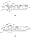
本発明に係る面ファスナーの一実施形態について、図面を使用しながら説明する。図1本発明に係る面ファスナーの一実施形態の模式的な斜視図である。図2(A)は、本発明に係る面ファスナーの一実施形態において、面ファスナー部材の模式的な平面図であり、図2(B)は、図2(A)のC-C線矢視部分断面図である。図3(A)は、図1のA-A線矢視部分断面図であり、図4(B)は、図4(A)の変形例である。図4は、本発明に係る面ファスナーの一実施形態において、面ファスナー部材の連結部が湾曲した状態である面ファスナー部材を示す模式的な平面図である。図5は、図1のB-B線矢視部分正面図である。図6は、本発明に係る面ファスナーの一実施形態において、第1セグメントと第2セグメントの係合状態を説明するための部分拡大図である。
図1に示すように、当該面ファスナー(100)は、互いに係合及び脱係合可能な第1面ファスナー部材(110)と第2面ファスナー部材(150)とからなる。
(面ファスナー部材)
図2(A)に示すように、第1面ファスナー部材(110)は、複数の第1セグメント(120、130、140)と、隣り合う第1セグメント(120、130、140)間を繋ぐ連結部(125、135)とを有する。第2面ファスナー部材(150)は、第1面ファスナー部材(110)と第2面ファスナー部材(150)とを係合するため、少なくとも1個の第2セグメント(160、170、180)を備えていれば特に限定されないが、第1面ファスナー部材(110)と同一の構造であってもよい。より詳しくは、第2面ファスナー部材(150)は、複数の第2セグメント(160、170、180)と、隣り合う第2セグメント(160、170、180)間を繋ぐ連結部(165、175)とを備える。
図2(A)に示すように、第1面ファスナー部材(110)は、複数の第1セグメント(120、130、140)と、隣り合う第1セグメント(120、130、140)間を繋ぐ連結部(125、135)とを有する。第2面ファスナー部材(150)は、第1面ファスナー部材(110)と第2面ファスナー部材(150)とを係合するため、少なくとも1個の第2セグメント(160、170、180)を備えていれば特に限定されないが、第1面ファスナー部材(110)と同一の構造であってもよい。より詳しくは、第2面ファスナー部材(150)は、複数の第2セグメント(160、170、180)と、隣り合う第2セグメント(160、170、180)間を繋ぐ連結部(165、175)とを備える。
(セグメント)
第1及び第2セグメント(120、130、140、160、170、180)それぞれは、基板(121、131、141、161、171、181)と、基板(121、131、141、161、171、181)から突出する多数の係合部(122、132、142、162、172、182)と、多数の係合部(122、132、142、162、172、182)間に規定される係合空間(123、133、143、163、173、183)とを有する。
第1及び第2セグメント(120、130、140、160、170、180)それぞれは、基板(121、131、141、161、171、181)と、基板(121、131、141、161、171、181)から突出する多数の係合部(122、132、142、162、172、182)と、多数の係合部(122、132、142、162、172、182)間に規定される係合空間(123、133、143、163、173、183)とを有する。
第1及び第2セグメント(120、130、140、160、170、180)の材質は、使用用途という観点から、軟質樹脂であることが好ましい。なお、第1及び第2セグメント(120、130、140、160、170、180)の材質は、第1及び第2面ファスナー部材(110、150)を成形機で成形するという観点から、連結部(125、135、165、175)と同一でもよい。
多数の係合部(122、132、142、162、172、182)は、基板(121、131、141、161、171、181)の一方の主表面の多数の箇所から突出する。多数の係合部(122、132、142、162、172、182)は、規則的に配列されている。ここで、第1及び第2セグメント(120、130、140、160、170、180)の係合部(122、132、142、162、172、182)は、図2(A)に示すように、第1及び第2セグメント(120、130、140、160、170、180)内に、縦3個、横3個を直角に配列しているが、これに限定されるものではなく、例えば縦横方向の間隔が45°斜め方向に配列されてもよい。
図2(B)に示すように、係合部(122、132、142、162、172、182)は、円柱状のステム(122a、132a、142a、162a、172a、182a)と、ステム(122a、132a、142a、162a、172a、182a)の先端から突出し、楕円体状の係合頭部(122b、132b、142b、162b、172b、182b)とから構成される。なお、本発明において、ステム(122a、132a、142a、162a、172a、182a)の形状は円柱状に限定されず、角柱状、円錐台状、逆円錐台状(図3(B)参照。)であってもよい。また、係合頭部(122b、132b、142b、162b、172b、182b)の形状は、楕円体状に限定されず、円板状、半球状、半楕円体状(図3(B)参照。)等であってもよい。また、係合頭部(122b、132b、142b、162b、172b、182b)は、第1及び第2面ファスナー部材(110、150)を成形機で成形するという観点から、ステム(122a、132a、142a、162a、172a、182a)と一体構造であってもよい。
係合頭部(122b、132b、142b、162b、172b、182b)の径は、ステム(122a、132a、142a、162a、172a、182a)の径よりも大きい。これにより、本発明の一実施形態では、第1及び第2セグメント(120、130、140、160、170、180)の多数の係合部(122、132、142、162、172、182)のうち少なくとも1個の係合部(122、132、142、162、172、182)の一部を第2及び第1セグメント(120、130、140、160、170、180)の係合空間(123、133、143、163、173、183)に受け入れた後、上下方向、左右方向、又は前後方向に第1及び第2セグメント(120、130、140、160、170、180)を移動させた場合、第1及び第2セグメント(120、130、140、160、170、180)の係合頭部(122b、132b、142b、162b、172b、182b)の基端部が、他の係合頭部(122b、132b、142b、162b、172b、182b)の基端部と接触する。その結果、第1セグメント(120、130、140)と第2セグメント(160、170、180)との係合が容易に外れない。なお、上記係合空間(123、133、143、163、173、183)は、第1セグメント(120、130、140)と第2セグメント(160、170、180)との係合した状態で、一方のセグメントの係合部(122、132、142、162、172、182)に対応する、他方のセグメントにおける縦2個、横2個の係合部(122、132、142、162、172、182)間の領域である。
また、係合頭部(122b、132b、142b、162b、172b、182b)の径とステム(122a、132a、142a、162a、172a、182a)の径は、いわゆる同心円状になっている。なお、図2(B)に示すように、係合頭部(122b、132b、142b、162b、172b、182b)の先端部は、例えば各セグメント(120、130、140、160、170、180)を金型による成形を実施した際に、その金型から抜き出しやすいという観点から、凹部状のくぼみ部を有する。なお、係合頭部(122b、132b、142b、162b、172b、182b)の先端部は、凹部状のくぼみ部を有さなくてもよい。
(係合空間)
係合空間(123、133、143、163、173、183)は、第1及び第2セグメント(120、130、140、160、170、180)の一方の多数の係合部(122、132、142、162、172、182)のうち少なくとも1本の係合部(122、132、142、162、172、182)の一部を他方の係合空間(123、133、143、163、173、183)に受け入れることにより、第1セグメント(120、130、140)と第2セグメント(160、170、180)とが係合する。このとき、係合空間(123、133、143、163、173、183)の中心線は、係合空間(123、133、143、163、173、183)内に係合部(122、132、142、162、172、182)を受け入れた際に係合頭部(122b、132b、142b、162b、172b、182b)の軸線と略一致する。
係合空間(123、133、143、163、173、183)は、第1及び第2セグメント(120、130、140、160、170、180)の一方の多数の係合部(122、132、142、162、172、182)のうち少なくとも1本の係合部(122、132、142、162、172、182)の一部を他方の係合空間(123、133、143、163、173、183)に受け入れることにより、第1セグメント(120、130、140)と第2セグメント(160、170、180)とが係合する。このとき、係合空間(123、133、143、163、173、183)の中心線は、係合空間(123、133、143、163、173、183)内に係合部(122、132、142、162、172、182)を受け入れた際に係合頭部(122b、132b、142b、162b、172b、182b)の軸線と略一致する。
図2(A)に示すように、第1及び第2セグメント(120、130、140、160、170、180)の基板(121、131、141、161、171、181)は、係合空間(123、133、143、163、173、183)に対応する箇所に凹部又は開口部を有する。凹部は、基板の一方の面に窪ませて形成した部分であることを示し、開口部は、基板を貫通して形成した部分であることを示す。また、第1及び第2セグメント(120、130、140、160、170、180)の基板(121、131、141、161、171、181)は、多数の係合部(122、132、142、162、172、182)からなる係合部群の外側であって、他方の係合部(122、132、142、162、172、182)に対応する箇所に凹部又は開口部を更に有する。図1に示すように、第1セグメント(120、130、140)と第2セグメント(160、170、180)とが係合した状態である場合には、第1及び第2セグメント(120、130、140、160、170、180)の多数の係合部(122、132、142、162、172、182)のうち少なくとも1個の係合部(122、132、142、162、172、182)の一部が第2及び第1セグメント(120、130、140、160、170、180)の凹部又は開口部に入り込む。そうすることで、面ファスナー(100)の嵩張りを低減することができ、外部からの衝撃により第1セグメント(120、130、140)と第2セグメント(160、170、180)との係合が容易に解除されない。また、当該面ファスナー(100)は、糸くずやほこりなどが付着しにくい構造となっている。従来の面ファスナーは、J字型等のフック状に起毛された面ファスナー部材又はループ状に密集して起毛された他方の面ファスナー部材に、糸くずやほこりなどが付着しやすかった。しかしながら、当該面ファスナー(100)においては、各セグメントにおいて基板が先述したように、第1セグメント(120、130、140)と第2セグメント(160、170、180)とが係合するだけであり、その第1及び第2セグメント(120、130、140、160、170、180)の多数の係合部(122、132、142、162、172、182)に糸くずやほこりなどが付着しにくく、更に係合力を維持するために定期的な手入れを必要としない。なお、上記基板(121、131、141、161、171、181)において、図2(A)に示すように、凹部又は開口部は、規則的に配列されている。
第1セグメント(120、130、140)と第2セグメント(160、170、180)とが係合したことで、図3(A)に示すように、第1セグメント(120)の係合頭部(122b)の先端部は、第2セグメント(160)の基板(161)の側壁面(161a)に当接する。第1セグメント(120、130、140)が上下方向、左右方向、又は前後方向に移動させた場合に、第1及び第2セグメント(120、130、140、160、170、180)の係合頭部(122b、132b、142b、162b、172b、182b)の基端部が、他の係合頭部(122b、132b、142b、162b、172b、182b)の基端部と接触し、更に第1セグメント(120)の係合頭部(122b)の先端部の外周面は、第2セグメント(160)の側壁面(161a)との間で摩擦が生じる。その結果、第1セグメント(120、130、140)と第2セグメント(160、170、180)との係合が容易に解除されない。なお、当該面ファスナー(100)は、上記基板(121、131、141、161、171、181)に、図2(A)に示すような凹部又は開口部が形成されていなくとも、第1及び第2セグメント(120、130、140、160、170、180)の係合部(122、132、142、162、172、182)が、対応する第1及び第2セグメント(120、130、140、160、170、180)の係合空間(123、133、143、163、173、183)に収容されるので、第1セグメント(120、130、140)と第2セグメント(160、170、180)とが係合する。
凹部又は開口部の距離(H)は、面ファスナー(100)の嵩張りを低減し、外部からの衝撃により第1及び第2面ファスナー部材(110、150)が外れないという観点から、係合頭部(122b、132b、142b、162b、172b、182b)の最大径(R)より小さく、係合頭部(122b、132b、142b、162b、172b、182b)の先端部の径(r)より大きい。これにより、第1セグメント(120、130、140)と第2セグメント(160、170、180)との係合を維持することができる。本発明において、凹部又は開口部の距離(H)は、凹部又は開口部内の側壁面(161a)から対向する側壁面(161a)までの最短距離である。なお、図3(B)に示すように、係合部(122)は、上方向に拡径である逆円錐台状のステム(122a)と、ステム(122a)の先が半楕円体状である係合頭部(122b)とからなるものでもよい。このような係合部(122)では、左右方向における凹部又は開口部の距離(H)は、係合頭部(122b、132b、142b、162b、172b、182b)の最大径(R)より小さく、係合頭部(122b、132b、142b、162b、172b、182b)の先端部の径(r)より大きい。これにより、第1セグメント(120、130、140)と第2セグメント(160、170、180)との係合を維持することができる。
(連結部)
図2(A)に示すように連結部(125、135、165、175)は、隣り合う第1セグメント(120、130、140)間を繋ぎ、第2セグメント(160、170、180)間を繋ぐ。そのため、図4に示すように、第1面ファスナー部材(110)と第2面ファスナー部材(150)は、その連結部(125、135、165、175)を起点に湾曲させることで、物品の湾曲部に柔軟に対応することが可能である。そのため、当該面ファスナー(100)は、第1セグメント(120、130、140)と第2セグメント(160、170、180)とが係合しても、開閉具としての機能を損なわない。
図2(A)に示すように連結部(125、135、165、175)は、隣り合う第1セグメント(120、130、140)間を繋ぎ、第2セグメント(160、170、180)間を繋ぐ。そのため、図4に示すように、第1面ファスナー部材(110)と第2面ファスナー部材(150)は、その連結部(125、135、165、175)を起点に湾曲させることで、物品の湾曲部に柔軟に対応することが可能である。そのため、当該面ファスナー(100)は、第1セグメント(120、130、140)と第2セグメント(160、170、180)とが係合しても、開閉具としての機能を損なわない。
第1セグメント(120、130、140)と第2セグメント(160、170、180)とが係合したことで、先述したように、一方のセグメントの多数の係合部(122、132、142、162、172、182)のうち少なくとも1個の係合部(122、132、142、162、172、182)の一部を他方のセグメントの係合空間(123、133、143、163、173、183)に受け入れる。更に、図5に示すように、第1面ファスナー部材(110)は、面ファスナー(100)の嵩張りを低減し、第1及び第2面ファスナー部材(110、150)による取り付けの自由度を高めるという観点から、隣り合う第1セグメント(120、130、140)間に、第2面ファスナー部材(150)の多数の係合部(162、172、182)のうち少なくとも係合部(162、172、182)の一部を係合及び脱係合可能に受け入れることができる係合空間(123、133、143)を有する。また、第2面ファスナー部材(150)は、隣り合う第2セグメント(160、170、180)間に、第1面ファスナー部材(150)の多数の係合部(122、132、142)のうち少なくとも係合部(122、132、142)の一部を係合及び脱係合可能に受け入れることができる係合空間(163、173、183)を有する。このとき、隣り合う第1セグメント(120、130、140)間及び第2セグメント(160、170、180)間の離間距離(D)は、面ファスナー(100)の嵩張りを低減し、外部からの衝撃により面ファスナー部材(110、150)が外れないという観点から、係合頭部(122b、132b、142b、162b、172b、182b)の最大径(R)より小さく、係合頭部(122b、132b、142b、162b、172b、182b)の先端部の径(r)より大きい。このような場合、係合頭部(122b、132b、172b、182b)は、他方のセグメントの基板(121、131、161、171)の側面(121b、131b、161b、171b)と、それに対向した、基板(131、141、171、181)の側面(131b、141b、171b、181b)とに当接される。第1セグメント(120、130、140)を上下方向左右方向、又は前後方向に移動させた場合に、第1及び第2セグメント(120、130、140、160、170、180)の係合頭部(122b、132b、142b、162b、172b、182b)の基端部が、他の係合頭部(122b、132b、142b、162b、172b、182b)の基端部と接触し、更に基板(121、131、141、161、171、181)の側面(121b、131b、141b、161b、171b、181b)は、この係合頭部(122b、132b、142b、162b、172b、182b)の先端部の外周面との間に摩擦が生じる。その結果、第1セグメント(120、130、140)と第2セグメント(160、170、180)との係合が容易に解除されない。
連結部(125、135、165、175)の材質は、物品の湾曲部や物品のひねり等に柔軟に対応するという観点から、軟質部材である。軟質部材としては、例えばセグメントと同質又は異質の軟質樹脂、紐、モノフィラメント等が挙げられる。これにより、外部からの衝撃が当該面ファスナー(100)を備えた物品に加わったとしても、第1セグメント(120、130、140)と第2セグメント(160、170、180)との係合が容易に解除されず、面ファスナー(100)がその物品から容易に外れない。連結部(125、135、165、175)の材質は、好ましくは軟質樹脂である。また、軟質樹脂としては、エラストマー樹脂であることが好ましく、適度な硬度と柔軟性を有していることを考慮し、例えばポリウレタン系、ポリエステル系、ポリアミド系、アクリル系、シリコーン系、ポリスチレン系、スチレンブタジエン系、ニトリルブタジエン系などの各種エラストマー樹脂が挙げられる。特に、エラストマー樹脂は、当該面ファスナー(100)を衣服などに使用するという観点から、ポリエステル系又はシリコーン系樹脂がより好ましい。なお、第1及び第2セグメント(120、130、140、160、170、180)と連結部(125、135、165、175)との材質は、射出成形や押出成形等の成形を容易に行うという観点から、同一の材質がよい。
図6に示すように、第1セグメント(120、130、140)と第2セグメント(160、170、180)との係合角度θ=45°となるように第1セグメント(120)と第2セグメント(160、170、180)とを係合してもよい。例えば、第2セグメント(160、170、180)の係合部(162、172、182)を縦横方向の間隔が45°斜め方向に配列すれば、第1セグメント(120、130、140)の多数の係合部(122、132、142)のうち少なくとも1個の係合部(122、132、142)の一部を第2セグメント(160、170、180)の係合空間(163、173、183)に受け入れ、且つ第2セグメント(160、170、180)の多数の係合部(162、172、182)のうち少なくとも1個の係合部(162、172、182)の一部を第1セグメント(120、130、140)の係合空間(123、133、143)に受け入れることができる。なお、本発明において係合角度(θ)は、第1セグメント(120、130、140)の基板(121、131、141)の主表面と、第2セグメント(160、170、180)の基板(161、171、181)の主表面とが交わって作る鋭角である。係合角度(θ)は、第1セグメント(120、130、140)と第2セグメント(160、170、180)が係合することができれば45°に限定されず、適宜調整可能である。そのような場合には、係合角度(θ)に併せて、第1及び第2セグメント(120、130、140、160、170、180)の係合部(122、132、142、162、172、182)の配置を適宜調整すればよい。
次に、本発明に係る面ファスナーの別の実施形態について、図面を使用しながら説明する。なお、先述した構成要素と重複する場合には、説明を割愛する。
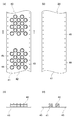
図7は、本発明に係る面ファスナーの別の実施形態の模式的な斜視図である。図8(A)は、本発明に係る面ファスナーの別の実施形態において、面ファスナー部材の模式的な平面図であり、図8(B)は、図8(A)のD-D線矢視部分正面図である。
当該面ファスナー(200)は、図7に示すように、互いに係合及び脱係合可能な第1面ファスナー部材(210)と第2面ファスナー部材(250)とからなる。
図8(A)に示すように、第1面ファスナー部材(210)は、複数の第1セグメント(220、230、240)と、隣り合う第1セグメント(220、230、240)間を繋ぐ軟質部材の連結部(225、235)とを有する。また、第2面ファスナー部材(250)は、第1面ファスナー部材(210)と同一構造であり、より詳しくは複数の第2セグメント(260、270、280)と、隣り合う第2セグメント(260、270、280)間を繋ぐ軟質部材の連結部(265、275)とを有する第2面ファスナー部材(250)とを備える。
第1及び第2セグメント(220、230、240、260、270、280)それぞれは、基板(221、231、241、261、271、281)と、基板(221、231、241、261、271、281)から突出する多数の係合部(222、232、242、262、272、282)と、多数の係合部(222、232、242、262、272、282)間に規定される係合空間(223、233、243、263、273、283)とを有する。なお、係合部(222、232、242、262、272、282)は、各セグメント(220、230、240、260、270、280)内に、縦4個、横4個を直角に配列しているが、これに限定されるものではなく、例えば縦横方向の間隔が45°斜め方向に配列されていてもよい。
図8(B)に示すように、係合部(222、232、242、262、272、282)は、円柱状のステム(222a、232a、242a、262a、272a、282a)と、ステム(222a、232a、242a、262a、272a、282a)の先端から突出し、楕円体状の係合頭部(222b、232b、242b、262b、272b、282b)とから構成される。
第1及び第2セグメント(220、230、240、260、270、280)の基板(221、231、241、261、271、281)は、係合空間(223、233、243、263、273、283)に対応する箇所に凹部又は開口部を有する。また、第1及び第2セグメント(220、230、240、260、270、280)の基板は、多数の係合部(222、232、242、262、272、282)からなる係合部群の外側であって、他方の係合部(222、232、242、262、272、282)に対応する箇所に凹部又は開口部を更に有する。これにより、第1及び第2セグメント(220、230、240、260、270、280)が係合した状態で、第1及び第2セグメント(220、230、240、260、270、280)の多数の係合部(222、232、242、262、272、282)のうち少なくとも1個の係合部(222、232、242、262、272、282)の一部が第2及び第1セグメント(220、230、240、260、270、280)の凹部又は開口部に入り込むことになる。なお、上記基板(221、231、241、261、271、281)は、凹部又は開口部が規則的に配列される。また、ミシン等で直接生地に縫着できるように、基板を貫通して形成される開口部はメッシュ状(図8(A)参照。)に構成されてもよい。
さらに、本発明に係る面ファスナーの別の実施形態について、図面を使用しながら説明する。なお、先述した構成要素と重複する場合には、説明を割愛する。
図9(A)は、本発明に係る面ファスナーの別の実施形態において、面ファスナー部材の模式的な平面図であり、図9(B)は、図9(A)のE-E線矢視部分正面図である。
当該面ファスナーは、図9(A)に示すように、互いに係合及び脱係合可能な第1面ファスナー部材(310)と第2面ファスナー部材(350)とからなる。
第1面ファスナー部材(310)は、複数の第1セグメント(320、330、340)と、隣り合う第1セグメント(320、330、340)間を繋ぐ軟質部材の連結部(325、335)とを有する。また、第2面ファスナー部材(350)は、第1面ファスナー部材(310)と同一構造であり、より詳しくは複数の第2セグメント(360、370、380)と、隣り合う第2セグメント(360、370、380)間を繋ぐ軟質部材の連結部(365、375)とを有する第2面ファスナー部材(350)とを備える。
第1及び第2セグメント(320、330、340、360、370、380)それぞれは、基板(321、331、341、361、371、381)と、基板(321、331、341、361、371、381)から突出する多数の係合部(322、332、342、362、372、382)と、多数の係合部(322、332、342、362、372、382)間に規定される係合空間(323、333、343、363、373、383)と、基板(321、331、341、361、371、381)の両端部の主表面上に、前後方向に延在した凹条溝部(324a、324b、334a、334b、344a、344b、364a、364b、374a、374b、384a、384b)とを有する。当該面ファスナーは、第1面ファスナー部材(310)と第2面ファスナー部材(350)が互いに係合した場合、凹条溝部(324a、324b、334a、334b、344a、344b、364a、364b、374a、374b、384a、384b)に縫製用糸を通すことで、各種の物品の面ファスナー被着部に縫製を容易にすることができる。また、係合部(322、332、342、362、372、382)は、各セグメント(320、330、340、360、370、380)内に、係合部(322、332、342、362、372、382)を係合空間(323、333、343、363、373、383)に入り込む数を増やすことで、第1面ファスナー部材(310)と第2面ファスナー部材(350)との係合を強化するという観点から、縦横方向の間隔が45°斜め方向に配列されている。上記係合部(322、332、342、362、372、382)の配列は、限定されるものではなく、縦と横で直角に配列してもよい。
図9(B)に示すように、係合部(322、362)は、円柱状のステム(322a、362a)と、ステム(322a、362a)の先端から突出し、半球状の係合頭部(322b、362b)とから構成される。なお、係合頭部(322b、362b)の形状は、先述したように、特に限定されるものではない。
第1及び第2セグメント(320、330、340、360、370、380)の基板(321、331、341、361、371、381)は、係合空間(323、333、343、363、373、383)に対応する箇所に凹部又は開口部を有する。例えば、係合空間(323、333、343、363、373、383)に対応する箇所に凹部を有する場合には、基板(321、331、341、361、371、381)は外部からの衝撃に対する変形又は割れが生じにくい。また、第1及び第2セグメント(320、330、340、360、370、380)の基板は、多数の係合部(322、332、342、362、372、382)からなる係合部群の外側であって、他方の係合部(322、332、342、362、372、382)に対応する箇所に凹部又は開口部を更に有する。これにより、第1及び第2セグメント(320、330、340、360、370、380)が係合した状態で、第1及び第2セグメント(320、330、340、360、370、380)の多数の係合部(322、332、342、362、372、382)のうち少なくとも1個の係合部(322、332、342、362、372、382)の一部が第2及び第1セグメント(320、330、340、360、370、380)の凹部又は開口部に入り込むことになる。なお、上記基板(321、331、341、361、371、381)は、凹部又は開口部が規則的に配列される。図9(A)に示す別の実施形態では、ミシン等で直接生地に縫着するために基板(321、331、341、361、371、381)を貫通して形成された開口部を備えていない替わりに、基板(321、331、341、361、371、381)の両端部の主表面上に、前後方向に延在した凹条溝部(324a、324b、334a、334b、344a、344b、364a、364b、374a、374b、384a、384b)を形成することで、直接生地に縫着することを可能にしている。
本発明に係る面ファスナー(100、200)は、一実施形態において、面ファスナー部材(110、150、210、250、310、350)と連結部(125、135、165、175、225、235、265、275、325、335、365、375)とを一体成形可能な任意の公知の手法によって製造すればよい。得られた面ファスナー(100、200)を各種の物品の面ファスナー被着部に縫着することによって、面ファスナー(100、200)を備えた物品が製造される。物品としては、例えば衣服、ポケット、鞄、靴(例:ブーツ、シューズ)、テント、ベッドのマット、車両用シート、建材などの開口部に使用することができる。
以上、本発明の実施形態について図面を参照しながら詳細に説明したが、本発明は上記の実施形態に限定されるものではなく、本発明の範囲内において種々の改変が可能である。
100、200 面ファスナー
110、210、310 第1面ファスナー部材
120、130、140、220、230、240、320、330、340 第1セグメント
121、131、141、161、171、181、221、231、241、261、271、281、321、331、341、361、371、381 基板
121b、131b、141b、161b、171b、181b 側面
122、132、142、162、172、182、222、232、242、262、272、282、322、332、342、362、372、382 係合部
122a、132a、142a、162a、172a、182a、222a、232a、242a、262a、272a、282a、322a、362a ステム
122b、132b、142b、162b、172b、182b、222b、232b、242b、262b、272b、282b、322b、362b 係合頭部
123、133、143、163、173、183、223、233、243、263、273、283、323、333、343、363、373、383 係合空間
125、135、165、175、225、235、265、275、325、335、365、375 連結部
150、250、350 第2面ファスナー部材
160、170、180、260、270、280、360、370、380 第2セグメント
161a 側壁面
324a、324b、334a、334b、344a、344b、364a、364b、374a、374b、384a、384b 凹条溝部
H:凹部又は開口部の距離
L:離間距離
R:最大径
r:先端部の径
θ:係合角度
110、210、310 第1面ファスナー部材
120、130、140、220、230、240、320、330、340 第1セグメント
121、131、141、161、171、181、221、231、241、261、271、281、321、331、341、361、371、381 基板
121b、131b、141b、161b、171b、181b 側面
122、132、142、162、172、182、222、232、242、262、272、282、322、332、342、362、372、382 係合部
122a、132a、142a、162a、172a、182a、222a、232a、242a、262a、272a、282a、322a、362a ステム
122b、132b、142b、162b、172b、182b、222b、232b、242b、262b、272b、282b、322b、362b 係合頭部
123、133、143、163、173、183、223、233、243、263、273、283、323、333、343、363、373、383 係合空間
125、135、165、175、225、235、265、275、325、335、365、375 連結部
150、250、350 第2面ファスナー部材
160、170、180、260、270、280、360、370、380 第2セグメント
161a 側壁面
324a、324b、334a、334b、344a、344b、364a、364b、374a、374b、384a、384b 凹条溝部
H:凹部又は開口部の距離
L:離間距離
R:最大径
r:先端部の径
θ:係合角度
Claims (8)
- 互いに係合及び脱係合可能な第1面ファスナー部材(110、210、310)と第2面ファスナー部材(150、250、350)とからなる面ファスナー(100、200)であって、
前記第1面ファスナー部材(110、210、310)は、複数の第1セグメント(120、130、140、220、230、240、320、330、340)と、隣り合う第1セグメント間を繋ぐ軟質部材の連結部(125、135、225、235、325、335)とを備え、
前記第2面ファスナー部材(150、250、350)は、少なくとも1個の第2セグメント(160、170、180、260、270、280、360、370、380)を備え、
前記第1及び第2セグメント(120、130、140、160、170、180、220、230、240、260、270、280、320、330、340、360、370、380)それぞれは、基板(121、131、141、161、171、181、221、231、241、261、271、281、321、331、341、361、371、381)と前記基板(121、131、141、161、171、181、221、231、241、261、271、281、321、331、341、361、371、381)から突出する多数の係合部(122、132、142、162、172、182、222、232、242、262、272、282、322、332、342、362、372、382)と前記多数の係合部(122、132、142、162、172、182、222、232、242、262、272、282、322、332、342、362、372、382)間に規定される係合空間(123、133、143、163、173、183、223、233、243、263、273、283、323、333、343、363、373、383)とを有し、
前記第1及び第2セグメント(120、130、140、160、170、180、220、230、240、260、270、280、320、330、340、360、370、380)の一方の多数の係合部(122、132、142、162、172、182、222、232、242、262、272、282、322、332、342、362、372、382)のうち少なくとも1個の係合部(122、132、142、162、172、182、222、232、242、262、272、282、322、332、342、362、372、382)の一部を他方の係合空間(123、133、143、163、173、183、223、233、243、263、273、283、323、333、343、363、373、383)に受け入れることにより、前記第1セグメント(120、130、140、220、230、240、320、330、340)と前記第2セグメント(160、170、180、260、270、280、360、370、380)とが係合する面ファスナー。 - 前記第1面ファスナー部材(110、210、310)は、隣り合う第1セグメント(120、130、140、220、230、240、320、330、340)間に、前記第2面ファスナー部材(150、250、350)の多数の係合部(162、172、182、262、272、282、362、372、382)のうち係合部(162、172、182、262、272、282、362、372、382)の一部を係合及び脱係合可能に受け入れることができる係合空間を有する請求項1に記載の面ファスナー。
- 前記第1及び第2セグメント(120、130、140、160、170、180、220、230、240、260、270、280、320、330、340、360、370、380)の前記基板(121、131、141、161、171、181、221、231、241、261、271、281、321、331、341、361、371、381)は、前記係合空間(123、133、143、163、173、183、223、233、243、263、273、283、323、333、343、363、373、383)に対応する箇所に凹部又は開口部を有し、前記第1及び第2セグメント(120、130、140、160、170、180、220、230、240、260、270、280、320、330、340、360、370、380)が係合した状態で、前記第1及び第2セグメント(120、130、140、160、170、180、220、230、240、260、270、280、320、330、340、360、370、380)の前記多数の係合部(122、132、142、162、172、182、222、232、242、262、272、282、322、332、342、362、372、382)のうち少なくとも1個の係合部(122、132、142、162、172、182、222、232、242、262、272、282、322、332、342、362、372、382)の一部が第2及び第1セグメント(120、130、140、160、170、180、220、230、240、260、270、280、320、330、340、360、370、380)の前記凹部又は開口部に入り込む請求項1又は2に記載の面ファスナー。
- 前記第1及び第2セグメント(120、130、140、160、170、180、220、230、240、260、270、280、320、330、340、360、370、380)の前記基板(121、131、141、161、171、181、221、231、241、261、271、281、321、331、341、361、371、381)は、前記多数の係合部(122、132、142、162、172、182、222、232、242、262、272、282、322、332、342、362、372、382)からなる係合部群の外側であって、他方の係合部(122、132、142、162、172、182、222、232、242、262、272、282、322、332、342、362、372、382)に対応する箇所に凹部又は開口部を更に有し、前記第1及び第2セグメント(120、130、140、160、170、180、220、230、240、260、270、280、320、330、340、360、370、380)が係合した状態で、前記第1及び第2セグメント(120、130、140、160、170、180、220、230、240、260、270、280、320、330、340、360、370、380)の前記多数の係合部(122、132、142、162、172、182、222、232、242、262、272、282、322、332、342、362、372、382)のうち少なくとも1個の係合部(122、132、142、162、172、182、222、232、242、262、272、282、322、332、342、362、372、382)の一部が第2及び第1セグメント(120、130、140、160、170、180、220、230、240、260、270、280、320、330、340、360、370、380)の前記凹部又は開口部に入り込む請求項3に記載の面ファスナー。
- 前記第1面ファスナー部材(110、210、310)と前記第2面ファスナー部材(150、250、350)とが、同一の構造である、請求項1~4のいずれか一項に記載の面ファスナー。
- 前記軟質部材は、軟質樹脂、紐、及びモノフィラメントよりなる群から選択される1種である、請求項1~5のいずれか一項に記載の面ファスナー。
- 前記軟質樹脂は、エラストマー樹脂である、請求項6に記載の面ファスナー。
- 請求項1~7のいずれか一項に記載の面ファスナー(100、200)を備えた物品。
Priority Applications (4)
| Application Number | Priority Date | Filing Date | Title |
|---|---|---|---|
| PCT/JP2018/047982 WO2020136779A1 (ja) | 2018-12-26 | 2018-12-26 | 面ファスナー |
| JP2020562030A JP7604231B2 (ja) | 2018-12-26 | 2018-12-26 | 面ファスナー |
| CN201880100017.0A CN113163906B (zh) | 2018-12-26 | 2018-12-26 | 搭扣带 |
| TW108117353A TW202023431A (zh) | 2018-12-26 | 2019-05-20 | 黏扣帶與具備黏扣帶的物品 |
Applications Claiming Priority (1)
| Application Number | Priority Date | Filing Date | Title |
|---|---|---|---|
| PCT/JP2018/047982 WO2020136779A1 (ja) | 2018-12-26 | 2018-12-26 | 面ファスナー |
Publications (1)
| Publication Number | Publication Date |
|---|---|
| WO2020136779A1 true WO2020136779A1 (ja) | 2020-07-02 |
Family
ID=71126979
Family Applications (1)
| Application Number | Title | Priority Date | Filing Date |
|---|---|---|---|
| PCT/JP2018/047982 Ceased WO2020136779A1 (ja) | 2018-12-26 | 2018-12-26 | 面ファスナー |
Country Status (4)
| Country | Link |
|---|---|
| JP (1) | JP7604231B2 (ja) |
| CN (1) | CN113163906B (ja) |
| TW (1) | TW202023431A (ja) |
| WO (1) | WO2020136779A1 (ja) |
Citations (5)
| Publication number | Priority date | Publication date | Assignee | Title |
|---|---|---|---|---|
| JPH0779812A (ja) * | 1993-09-06 | 1995-03-28 | Minnesota Mining & Mfg Co <3M> | 対面係合ファスナー部材 |
| JP2003533314A (ja) * | 2000-05-23 | 2003-11-11 | ベルクロ インダストリーズ ビー ヴィッ | セグメント化された着脱可能な締結具 |
| JP2010068928A (ja) * | 2008-09-17 | 2010-04-02 | Morito Co Ltd | 面ファスナ |
| WO2012120618A1 (ja) * | 2011-03-07 | 2012-09-13 | Ykk株式会社 | 成形面ファスナー |
| JP2016028768A (ja) * | 2010-07-16 | 2016-03-03 | ジェラルド・ロシャ | 次元的に柔軟なタッチ・ファスナー・ストリップ |
Family Cites Families (4)
| Publication number | Priority date | Publication date | Assignee | Title |
|---|---|---|---|---|
| JP3474686B2 (ja) * | 1995-08-30 | 2003-12-08 | Ykk株式会社 | 面ファスナーとその製造方法 |
| JPH09157921A (ja) * | 1995-11-30 | 1997-06-17 | Ykk Corp | 緊締用ベルト |
| JP2002165615A (ja) * | 2000-11-30 | 2002-06-11 | Ykk Corp | スナップファスナー |
| US7950114B2 (en) | 2004-03-10 | 2011-05-31 | Leonard Arnold Duffy | Self-adhering device and method |
-
2018
- 2018-12-26 JP JP2020562030A patent/JP7604231B2/ja active Active
- 2018-12-26 CN CN201880100017.0A patent/CN113163906B/zh active Active
- 2018-12-26 WO PCT/JP2018/047982 patent/WO2020136779A1/ja not_active Ceased
-
2019
- 2019-05-20 TW TW108117353A patent/TW202023431A/zh unknown
Patent Citations (5)
| Publication number | Priority date | Publication date | Assignee | Title |
|---|---|---|---|---|
| JPH0779812A (ja) * | 1993-09-06 | 1995-03-28 | Minnesota Mining & Mfg Co <3M> | 対面係合ファスナー部材 |
| JP2003533314A (ja) * | 2000-05-23 | 2003-11-11 | ベルクロ インダストリーズ ビー ヴィッ | セグメント化された着脱可能な締結具 |
| JP2010068928A (ja) * | 2008-09-17 | 2010-04-02 | Morito Co Ltd | 面ファスナ |
| JP2016028768A (ja) * | 2010-07-16 | 2016-03-03 | ジェラルド・ロシャ | 次元的に柔軟なタッチ・ファスナー・ストリップ |
| WO2012120618A1 (ja) * | 2011-03-07 | 2012-09-13 | Ykk株式会社 | 成形面ファスナー |
Also Published As
| Publication number | Publication date |
|---|---|
| JP7604231B2 (ja) | 2024-12-23 |
| TW202023431A (zh) | 2020-07-01 |
| CN113163906A (zh) | 2021-07-23 |
| JPWO2020136779A1 (ja) | 2021-09-27 |
| CN113163906B (zh) | 2023-01-17 |
Similar Documents
| Publication | Publication Date | Title |
|---|---|---|
| JP5506775B2 (ja) | スナップボタン | |
| US3808648A (en) | Separable fastening sheet | |
| EP0657130B1 (en) | Fastening device | |
| TW378160B (en) | Toy building blocks | |
| KR950001606Y1 (ko) | 성형된 표면 파스너 | |
| JPH10201504A (ja) | 一体成形により得られる面ファスナー用係合部材 | |
| US3401434A (en) | Snap fastener assembly | |
| KR20130091725A (ko) | 임시 고정 기능이 우수한 면 파스너 | |
| JP2559017Y2 (ja) | 一体成形面ファスナー | |
| ITTO20001014A1 (it) | Dispositivo di aggancio. | |
| KR101594269B1 (ko) | 슬라이드 파스너 및 은폐 슬라이드 파스너 | |
| EP1481603A1 (en) | Male fixing member of hook-and loop fastener, and sheet product with the fixing member | |
| WO2020136779A1 (ja) | 面ファスナー | |
| JP6492363B2 (ja) | 位置合わせ機能に優れた雄型面ファスナー | |
| JP5399028B2 (ja) | 面ファスナ | |
| US20170156451A1 (en) | Injection molded mushroom type hook structure and hook strap including the same | |
| US20020007534A1 (en) | Fasteners | |
| US6694573B2 (en) | Snap with supports | |
| KR20250155560A (ko) | 스프링 연결 부재, 탄성 모듈 및 탄성 패드 | |
| EP3558048A1 (en) | Zip fastener with closure with couplable profiles | |
| US10369909B2 (en) | Surface fastener, cushioning structure, and seat structure | |
| JP3230435U (ja) | 留め具およびこれを備える衣類 | |
| JP5513607B2 (ja) | ファスナー部品 | |
| JP4121980B2 (ja) | スナップファスナー | |
| JP2553258Y2 (ja) | ホモタイプの面ファスナー用雄面およびそれを用いたホモタイプの面ファスナー |
Legal Events
| Date | Code | Title | Description |
|---|---|---|---|
| 121 | Ep: the epo has been informed by wipo that ep was designated in this application |
Ref document number: 18944491 Country of ref document: EP Kind code of ref document: A1 |
|
| ENP | Entry into the national phase |
Ref document number: 2020562030 Country of ref document: JP Kind code of ref document: A |
|
| NENP | Non-entry into the national phase |
Ref country code: DE |
|
| 122 | Ep: pct application non-entry in european phase |
Ref document number: 18944491 Country of ref document: EP Kind code of ref document: A1 |