WO2020129522A1 - 画像処理装置 - Google Patents
画像処理装置 Download PDFInfo
- Publication number
- WO2020129522A1 WO2020129522A1 PCT/JP2019/045357 JP2019045357W WO2020129522A1 WO 2020129522 A1 WO2020129522 A1 WO 2020129522A1 JP 2019045357 W JP2019045357 W JP 2019045357W WO 2020129522 A1 WO2020129522 A1 WO 2020129522A1
- Authority
- WO
- WIPO (PCT)
- Prior art keywords
- light source
- unit
- brightness
- image processing
- threshold value
- Prior art date
- Legal status (The legal status is an assumption and is not a legal conclusion. Google has not performed a legal analysis and makes no representation as to the accuracy of the status listed.)
- Ceased
Links
Images



Classifications
-
- G—PHYSICS
- G06—COMPUTING OR CALCULATING; COUNTING
- G06T—IMAGE DATA PROCESSING OR GENERATION, IN GENERAL
- G06T7/00—Image analysis
-
- G—PHYSICS
- G08—SIGNALLING
- G08G—TRAFFIC CONTROL SYSTEMS
- G08G1/00—Traffic control systems for road vehicles
- G08G1/16—Anti-collision systems
Definitions
- the present invention relates to an image processing device mounted on a vehicle.
- a region having a certain brightness or higher is set as a light source region on the image. Then, it is determined whether it is a headlight or a reflector by using the threshold value of the distance to the light source region and the relationship between the brightness.
- Patent Document 1 the high beam/low beam state of the vehicle is used.
- the high beam is high, the reflected light becomes strong, so that the brightness threshold is strict, and when the low beam is low, the reflected light becomes weak, so the brightness threshold is low. It is described that the processing to be performed is performed.
- An object of the present invention is to realize an image processing apparatus capable of accurately discriminating between a headlight and a reflector regardless of the distance from the vehicle and the brightness of the reflector or headlight. To do.
- the present invention is configured as follows to achieve the above object.
- an image acquisition unit that acquires a captured image captured by an imaging device, and a brightness calculation that divides the captured image acquired by the image acquisition unit into a plurality of pixel regions and calculates the brightness of each pixel region.
- a light source region setting unit configured to set a region including a plurality of adjacent pixel regions in which the brightness calculated by the brightness calculation unit is equal to or higher than a set brightness as a light source region, and the light source region setting unit.
- a threshold value determination unit that determines a threshold value for each of the plurality of light source regions, and an object identification unit that identifies an object by using the threshold value determined by the threshold value determination unit.
- FIG. 1 is a schematic configuration diagram of a vehicle control system according to an embodiment of the present invention.
- a vehicle control system (also a light distribution control system) 100 is provided in a vehicle (sometimes referred to as a host vehicle), is installed in front of the vehicle, and periodically displays an image of a predetermined area in front of the vehicle.
- a camera (imaging device) 11 that captures images in time series
- an image processing device 1 that processes an image (captured image) captured by the camera 11, and a vehicle control device that controls a vehicle based on the processing result of the image processing device 1. Equipped with 2.
- the image processing device 1 and the vehicle control device 2 are each a computer (for example, a microcomputer), and include, for example, an input unit (not shown), a central processing unit 3 (CPU or MPU) that is a processor, and a storage device 4. It has a read only memory (ROM) and a random access memory (RAM), and an output unit (not shown).
- a computer for example, a microcomputer
- CPU or MPU central processing unit 3
- RAM random access memory
- an input unit converts various information input to the image processing device 1 and the vehicle control device 2 so that the CPU can calculate the information.
- the ROM is a recording medium that stores a control program that appropriately executes arithmetic processing described later and various information necessary for executing the arithmetic processing.
- the CPU is an input unit and a ROM according to the control program stored in the ROM. , A predetermined arithmetic processing is performed on the signal received from the RAM.
- Output commands of the image processing device 1 and the vehicle control device 2 output commands for controlling the output target and information used by the output target.
- the storage device 4 is not limited to the semiconductor memory such as the ROM and RAM described above, and can be replaced by a magnetic storage device such as a hard disk drive.
- the image processing apparatus 1 is a computer that executes external environment recognition processing including object detection based on a captured image (color image) of the camera 11, and includes an image acquisition unit 12, a brightness calculation unit 13, and a light source region setting unit. 14, a threshold value determination unit 15, an object identification unit 16, and an irradiation direction information acquisition unit 17 are provided.
- the vehicle control device 2 is a computer that executes vehicle control processing based on the detection result of the object identifying unit 16 output from the image processing device 1, and includes a light distribution control unit 18.
- the image processing apparatus 1 and the vehicle control apparatus 2 in FIG. 1 are configured by two different computers, they may be configured by an integrated computer.
- the image acquisition unit 12 controls the camera 11, periodically sets and sets an exposure time (shutter speed) to acquire a time series of a color image, and executes processing of storing them in the image processing apparatus 1.
- the color image is defined by the RGB color model, and the color of each pixel forming the color image is defined by the combination of the brightness of red (R), green (G), and blue (B).
- the brightness of each of R, G, and B is expressed by an integer value from 0 to 255 (that is, 256 gradations), and the color of each pixel is represented by three values (R value, G value, B value). It is defined by the combination of.
- the color image is captured at a predetermined cycle, and for example, 30 frames may be captured per second.
- the brightness calculation unit 13 calculates the brightness index value of a predetermined area located in the center of the brightness image generated in the past (for example, before a predetermined frame) and the information of the predetermined target object to be detected by the target object identification unit 16.
- the brightness calculation formula is changed/determined according to the output of the object identifying unit 16 including the output and the output of the vehicle control device 2 including the information of the application executed by the vehicle control device 2. This is to adjust the constants of the brightness calculation formula and the like to sharpen the image when the external environment of the own vehicle changes abruptly, and the information such as the predetermined target object to be detected is the target object identification unit 16 Is output to the brightness calculation unit 13.
- Each luminance calculation formula is defined by the sum of the values obtained by multiplying the R value, G value, and B value by a predetermined coefficient, and the luminance calculation unit 13 uses this formula to calculate the R value of the pixels forming the color image, The brightness of the pixel is calculated by substituting the G value and the B value.
- a luminance image is obtained by calculating the luminance of each pixel of the image captured by the camera 11 and collecting the pixels.
- the light source region setting unit 14 detects a pixel region 41 (shown in FIG. 6, which is an explanatory diagram of the light source region and the pixel region) having a luminance equal to or higher than a setting threshold, based on the luminance image output from the luminance calculation unit 13, Adjacent pixel areas 41, which are pixels having a brightness equal to or higher than the set threshold value, are integrated as described later to form a vehicle candidate area (light source area) 42 (shown in FIG. 6).
- a variance value is calculated as a value representing the area of the vehicle candidate area, the maximum brightness, and the variation in brightness, and the process of storing them in the storage device 4 in the image processing apparatus 1 is executed.
- the value representing the variation in luminance is not limited to the variance value, and can be replaced by, for example, the standard deviation, and when the variance value or the standard deviation is equal to or greater than the set variance value or the set standard deviation, the light source is identified as a reflector. ..
- the threshold value determination unit 15 of the present embodiment for each light source region, based on the light source region information output from the light source region setting unit 14 and the irradiation direction information of the vehicle headlight output from the irradiation direction information acquisition unit 17. To set the threshold individually. Therefore, the threshold value can be changed with respect to the light source region that appears at the timing when the vehicle headlight switches from the low beam to the high beam.
- the switching of the vehicle headlights that change the threshold value is not limited to the timing of switching from the low beam to the high beam, and can be switched to the timing of switching from the high beam to the low beam, for example.
- the central processing unit 3 of the image processing apparatus 1 of the present embodiment acquires an irradiation direction information acquisition unit 17 that obtains information on the irradiation direction of the headlight of the vehicle, a camera (imaging device) 11, and a captured image of the camera 11.
- a light source region setting unit 14 that sets a light source region 42 that includes a plurality of adjacent pixel regions 41 that have a brightness equal to or higher than a set brightness (for example, a brightness that can detect a headlight 600 m or more ahead), and a light source region setting unit 14 Based on the plurality of light source regions 42 set by the above and the irradiation direction of the headlight acquired by the irradiation direction information acquisition unit 17, the threshold value determination unit 15 determines the threshold value for each light source region 42 and the threshold value determination unit 15.
- An object identifying unit 16 that identifies an object using a threshold value.
- the threshold value determining unit 15 of the central processing unit 3 of the image processing apparatus 1 of the present embodiment detects that the headlight is switched from the low beam to the high beam based on the information on the irradiation direction, and is set by the light source region setting unit 14. With respect to the light source region 42, the threshold value for identifying the object by the object identifying unit 16 is changed for each light source region 42.
- the object identifying unit 16 of the present embodiment executes a process of identifying a target object whose vehicle candidate region is a predetermined object using the color image acquired by the image acquiring unit 12 and the output of the light source region setting unit 14, and the identification is performed. The result is output to the vehicle control device 2.
- the “predetermined object” to be identified by the object identifying unit 16 may be determined by the type of application (program) executed by the vehicle control device 2.
- the light source area setting unit 14 calculates the area of the light source area 42 and the maximum brightness in the plurality of pixel areas 41 included in the light source area 42. It Then, the object identifying unit 16 identifies whether the light source area 42 set by the light source area setting unit 14 is an object or a reflective object by using the threshold determined by the threshold determining unit 15.
- the reflective object is the same as that of the own vehicle. It is the reflection of the headlights, and the headlights and tail lamps that emit light by themselves are brighter and have higher brightness. Therefore, by comparing the brightest part in the light source area with the size of the light source area, a large reflective object such as a signboard or a sign can be recognized as something other than a headlight or a tail lamp.
- the light source region setting unit 14 determines the object region and the reflector region based on the luminance distribution of the pixel regions 41 included in the light source region 42. Then, the object identifying unit 16 identifies whether the light source region 42 set by the light source region setting unit 14 is the object region or the reflector region by using the threshold determined by the threshold determining unit 15.
- FIG. 7 which is a figure which shows an example of a gaze guide (delineator)
- 4A has a small rectangular area of the light source region 42, and in the maximum brightness distribution 22 shown in FIG. 4B, the headlight 21a (FIG. 4A) and the tail lamp (FIG. 4A). Since the circle mark) and the mark (x mark) overlap, it is not possible to completely distinguish the headlight or tail lamp from the other marks because of the brightness and size.
- the headlight and the tail lamp are self-luminous, and therefore the headlight brightness is high.
- the distribution 31 there is a large variation in brightness within the light source region 42, and since the gaze guide (delineator) 51 is reflected, the variation in brightness is small as shown in the derivator luminance distribution 32. .. Therefore, as shown in the graph 33 of FIG. 5C, by comparing the brightness distributions of the light source regions 42 indicating the relationship between the dispersion value and the distance and separating them by the set threshold 34, the gaze target ( Small reflectors such as delineator 51 can be distinguished from other than headlights and tail lamps.
- the central processing unit 3 of the image processing apparatus 1 is an image that acquires the imaged image of the irradiation direction information acquisition unit 17 that acquires information on the irradiation direction of the headlight of the vehicle, the imaging device 11, and the imaging device 11.
- the acquisition unit 12, the brightness calculation unit 13 that divides the image acquired by the image acquisition unit 12 into a plurality of regions 41 and calculates the brightness of each pixel region 41, and the brightness calculated by the brightness calculation unit 13 is the set brightness.
- the light source area setting unit 14 which is set as the light source area 42 including the plurality of adjacent pixel areas 41, the plurality of light source areas 42 set by the light source area setting unit 14, and the irradiation direction information acquisition unit 17 are acquired.
- the threshold value determination unit 15 that determines a threshold value for each light source region 42 based on the irradiation direction of the headlight, the area of each of the plurality of light source regions 42, and the brightness of each of the pixel regions 41 of the plurality of light source regions 42.
- the threshold value determined by the threshold value determining unit 15 is used to identify the light source located in the light source region 42 based on the.
- the threshold value for each light source area in the threshold value determining unit 15 By changing the threshold value for each light source area in the threshold value determining unit 15 based on the information of the irradiation direction of the headlight of the vehicle, for example, the light source area that appears at the timing when the irradiation direction of the headlight changes has a severe threshold value.
- the central processing unit 3 of the image processing apparatus 1 is an image that acquires the imaged image of the irradiation direction information acquisition unit 17 that acquires information on the irradiation direction of the headlight of the vehicle, the imaging device 11, and the imaging device 11.
- the acquisition unit 12, the brightness calculation unit 13 that divides the image acquired by the image acquisition unit 12 into a plurality of pixel regions 41, and calculates the brightness of each pixel region 41, and the brightness calculated by the brightness calculation unit 13 is set.
- the light source region setting unit 14 that sets the light source region 42 that includes a plurality of adjacent pixel regions 41 that have brightness or higher, the plurality of light source regions 42 that are set by the light source region setting unit 14, and the irradiation direction information acquisition unit 17.
- a threshold value determination unit 15 that determines a threshold value for each light source region 42 based on the acquired irradiation direction of the headlight, and a distribution of the brightness of each pixel region 41 included in the light source region 42 set by the light source region setting unit 14.
- the threshold value determined by the threshold value determining unit 15 is used to identify the light source located in the light source region 42 based on the.
- the threshold value determining unit 15 By changing the threshold value for each light source area in the threshold value determining unit 15 based on the information of the irradiation direction of the headlight of the vehicle, for example, the light source area that appears at the timing when the irradiation direction of the headlight changes has a severe threshold value.
- the target identifying unit 16 uses the changed threshold value to perform the identification using the distribution of the luminance of the light source region, so that it is possible to identify the object or the reflector.
- the central processing unit 3 of the image processing apparatus 1 is an image that acquires the imaged image of the irradiation direction information acquisition unit 17 that acquires information on the irradiation direction of the headlight of the vehicle, the imaging device 11, and the imaging device 11.
- the acquisition unit 12, the brightness calculation unit 13 that divides the image acquired by the image acquisition unit 12 into a plurality of regions 41 and calculates the brightness of each pixel region 41, and the brightness calculated by the brightness calculation unit 13 is the set brightness.
- the light source area setting unit 14 which is set as the light source area 42 including the plurality of adjacent pixel areas 41, the plurality of light source areas 42 set by the light source area setting unit 14, and the irradiation direction information acquisition unit 17 are acquired.
- the threshold value determination unit 15 that determines a threshold value for each light source region 42 based on the irradiation direction of the headlight, the area of each of the plurality of light source regions 42, and the brightness of each of the pixel regions 41 of the plurality of light source regions 42. , The light source located in the light source region 42 based on the luminance distribution of each pixel region 41 included in the light source region 42 set by the light source region setting unit 14 using the threshold determined by the threshold determination unit 15 Identify whether it is a reflector or a reflector.
- the threshold value for each light source area in the threshold value determining unit 15 By changing the threshold value for each light source area in the threshold value determining unit 15 based on the information of the irradiation direction of the headlight of the vehicle, for example, the light source area that appears at the timing when the irradiation direction of the headlight changes has a severe threshold value. , It is possible to discriminate between the light source and the reflector with a higher degree of freedom than to discriminate all the light source regions by a constant threshold, such as setting a low threshold for the other light source regions. Become. Further, it is possible to discriminate between the target object and the reflection plate by performing the discrimination using the relationship between the luminance and the area of the light source region and the luminance distribution of the light source region in the object discriminating unit 16 using the changed threshold value. it can.
- the object identifying unit 16 includes the area of each of the plurality of light source regions 42, the brightness of each of the pixel regions 41 of each of the plurality of light source regions 42, and the light source region. Based on the luminance distribution of each pixel area 41 included in the light source area 42 set by the setting unit 14, whether the light source located in the light source area 42 is a target or a reflector is identified. Since the reflective object such as a sign or a signboard is a reflection of the headlight of the own vehicle, the brightness representing the brightness on the image tends to be lower than that of the headlight or the tail lamp.
- the headlight having a rectangular area in the same light source region and the sign or signboard can be separated according to the difference in brightness.
- a small reflector such as a gaze guide (delineator) is smaller in size than a headlight, and it is difficult to identify it in terms of area and brightness. Therefore, paying attention to the variation in brightness of the light source area, headlights and tail lamps that are self-luminous objects have a large variation from a bright area to a dark area, and a gaze guide (derinator) that is a reflective object tends to have a small variation. Therefore, it is possible to identify by utilizing the variation in brightness. Therefore, by combining two of the relationship between the area and the brightness and the relationship of the variation in the brightness, it is possible to take a countermeasure against the erroneous detection of the sign, the signboard, and the gaze guide (deriniator).
- the object identifying unit 16 of the central processing unit 3 of the image processing apparatus 1 includes pixels of the plurality of light source regions 42 for respective areas of the plurality of light source regions 42 set by the light source region setting unit 14.
- the ratio of the maximum brightness of the area 41 is equal to or greater than the set threshold value 23, the light source area 42 is determined as the object.
- the object identifying unit 16 of the central processing unit 3 of the image processing apparatus 1 includes pixels of the plurality of light source regions 42 for respective areas of the plurality of light source regions 42 set by the light source region setting unit 14.
- the light source area 42 is determined to be a reflector.
- the reflectors such as signs and billboards are reflections of the headlights of the own vehicle, the brightness on the image will be darker than that of the headlights when the rectangular areas of the light source region 42 are compared. Therefore, if the ratio of brightness to size is less than the set threshold value 23, it can be determined as a reflector.
- the object identifying unit 16 of the central processing unit 3 of the image processing apparatus 1 of the present embodiment determines that the variance value or the standard deviation value of the brightness of each pixel region 41 of the light source region 42 set by the light source region setting unit 14 is When the threshold value is equal to or greater than the set threshold value 34, the light source region 42 is determined to be an object.
- the headlights and tail lamps are self-luminous objects, the variation in brightness in the light source area is larger than that of the reflective objects such as the line-of-sight guide (delineator) 51 (headlight luminance distribution in FIG. 5A). 31). Therefore, when the variance value of brightness or the standard deviation is equal to or more than the set threshold value 34, it can be determined as an object.
- the object identification unit 16 of the central processing unit 3 of the image processing apparatus 1 of the present embodiment sets the luminance dispersion value or standard deviation of each pixel region 41 of the light source region 42 set by the light source region setting unit 14. When it is less than the threshold value 34, the light source region 42 is determined to be a reflector.
- Reflectors such as the line-of-sight guide (delineator) 51 have smaller variations in brightness (derinator brightness distribution 32) in the light source area than headlights. Therefore, when the variance value or standard deviation of brightness is less than the set threshold value 34, it can be identified as a reflective object.
- the light distribution control system 100 includes an irradiation direction information acquisition unit 17 that acquires information on the irradiation direction of the headlights of the vehicle, an imaging device 11, and an image acquisition unit 12 that acquires a captured image of the imaging device 11.
- the image acquired by the image acquisition unit 12 is divided into a plurality of pixel regions 41, and the brightness calculation unit 13 that calculates the brightness of each pixel region 41 and the brightness calculated by the brightness calculation unit 13 are equal to or higher than the set brightness.
- a threshold value determination unit 15 that determines a threshold value for each light source region 42 based on the irradiation direction of the light source region 42, the area of each of the plurality of light source regions 42, the brightness of each pixel region 41 of each of the plurality of light source regions 42, and the light source region. Based on the luminance distribution of each pixel region 41 included in the light source region 42 set by the setting unit 14, the light source located in the light source region 42 is identified by using the threshold determined by the threshold determining unit 15.
- the image processing apparatus 1 including the object identifying unit 16 and the light distribution control unit 18 that performs light distribution control based on the light-shielding region of the headlamp determined based on the identification result of the object identifying unit 16.
- the light distribution control unit 18 in the vehicle control device 2 executes light distribution control (light distribution control application) of the own vehicle headlight based on the identification result (vehicle detection result) of the object identification unit 16 of the image processing device 1. To do.
- the light distribution control for example, when the preceding vehicle and the oncoming vehicle are not present in front of the own vehicle, the own vehicle headlight is set to the high beam, and when the preceding vehicle or the oncoming vehicle is present, the own vehicle headlight is set to the low beam. There is something to do.
- the light shielding area of the own vehicle headlight is determined so that the other vehicle is excluded from the irradiation area of the own vehicle headlight, and the own vehicle is based on the light shielding area.
- the own vehicle is provided with an actuator (for example, a plurality of motors) that changes the optical axes of a plurality of headlights, and a shade mechanism for blocking a part of the light of each headlight.
- the control signal for them is output from the unit 18.
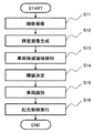
- FIG. 2 is a flowchart of a light distribution control process by the light distribution control system 100.
- the flow of the light distribution control process will be described with reference to FIG.
- the light distribution control system 100 (the image processing device 1 and the vehicle control device 2) repeatedly executes the flowchart of FIG. 2 at a predetermined control cycle.
- the image acquisition unit 12 sets the exposure time of the image to be captured next to the camera 11 in step S11, and captures the image at a predetermined timing to obtain a color image (captured image).
- step S12 the brightness calculation unit 13 generates a brightness image according to the brightness calculation formula.
- step S13 the light source region setting unit 14 sets, for the luminance image generated in step S12, a plurality of vehicle candidate regions (light source regions 42) including luminance pixels (pixel regions 41) having a certain reference value or more. ) Is calculated.
- step S14 the threshold value determination unit 15 based on the irradiation direction information of the vehicle headlight from the irradiation direction information acquisition unit 17 for each of the plurality of vehicle candidate regions (light source regions 42) calculated in step S13. Determine the threshold.
- step S15 the object identifying unit 16 determines that each area is a predetermined object based on the threshold value determined in step S14 for the plurality of vehicle candidate areas (light source areas 42) calculated in step S13. It is determined whether or not there is an object identification process (vehicle identification process).
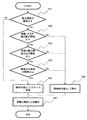
- step 15 the vehicle identification processing in step 15 will be described.
- FIG. 3 is a flowchart of vehicle identification processing in this embodiment.
- step S21 when the object identifying unit 16 starts the vehicle identifying process, in step S21, it is determined whether or not the maximum brightness is less than or equal to a threshold value, thereby determining whether to perform the filter process based on the maximum brightness. If the maximum brightness is not less than or equal to the threshold value in step S21, the process proceeds to step S25. If the maximum brightness is less than or equal to the threshold value, the process proceeds to step S22.
- step S22 whether the distance to the vehicle is an invalid value, whether the size (size) of the vehicle candidate area is equal to or greater than a certain value, or the actual size obtained by the distance and the size of the vehicle candidate area is large. It is checked by comparing with a threshold value whether the lateral position is too far from the lane, and if there is no problem, the process proceeds to the next step S23. If there is a problem in step S22, the process proceeds to step S26, and the object other than the predetermined object is excluded (excluded as a false detection object).
- step S23 it is determined whether or not the ratio of the area of the vehicle candidate region to the maximum brightness is equal to or more than a threshold value, and if the ratio of the area of the vehicle candidate region to the maximum brightness is equal to or more than the threshold value, it is determined to be a predetermined object, Proceed to the next step S24.
- step S23 if the above-mentioned ratio is less than the threshold value, the process proceeds to step S26, and it is determined that the object is not a predetermined object.
- step S24 it is determined whether or not the variance value of the brightness of the vehicle candidate area is equal to or more than a threshold value. If the variance value is equal to or more than the threshold value, it is determined that the object is a predetermined object, and the process proceeds to the next step S25. If the value is less than the threshold value 34 in step S24, the process proceeds to step S26, and it is determined that the object is outside the predetermined object.
- step S25 the vehicle candidate areas that have passed through steps S22, S23, and S24 are saved as a group as a detection target.
- step S27 a vehicle threshold area equal to or greater than the threshold is identified as a predetermined object by the stored luminance threshold value for each distance of the vehicle candidate zone.
- step S15 Information is added to the vehicle candidate area determined to be the predetermined object in step S15 to the effect that the area is to be shaded, and output to the light distribution control unit 18. Further, information indicating that the vehicle is not a light-shielding target is added to the vehicle candidate region determined to be not the predetermined target in step S15, and the information is output to the light distribution control unit 18, and the process proceeds to step S16.
- step S16 the light distribution control unit 18 determines the light blocking area of the vehicle headlight based on the output information of the object identifying unit 16, and excludes the light blocking area from the light blocking area of the vehicle headlight.
- the light distribution control of the own vehicle headlight is performed.
- the light distribution control system waits for a predetermined control cycle, and then executes a series of processes again from step S11.
- the threshold value for the light source area detected at the timing when the irradiation direction of the headlight of the vehicle is switched by changing the threshold value for the light source area detected at the timing when the irradiation direction of the headlight of the vehicle is switched, a different threshold value is set for each light source area. ..
- the light source detected at the timing of switching from the low beam to the high beam is likely to be a reflective object, and it is possible to distinguish the headlight or tail lamp from the reflective object by strictly setting the threshold used in the identification process in the subsequent stage. it can.
- the headlights and tail lamps are self-luminous, and the reflective objects such as signs and signs are reflections of the headlights of the vehicle. And tail lamps appear brighter in the image. Therefore, it is possible to classify the headlight, the tail lamp, and the reflector according to the ratio of the size and the brightness on the image.
- the size of the gaze target which is smaller than the headlights and tail lamps and cannot be classified by the ratio of size and brightness, has less variation in brightness on the image than headlights and tail lamps. Therefore, the headlight or tail lamp and the delineator can be classified by using the variance value or the standard deviation value of the brightness of the light source region.
- the threshold value determining unit 15 determines the threshold value by also considering the irradiation direction information of the headlamp of the own vehicle supplied from the irradiation direction information acquisition unit 17, but the light source region setting unit. It is also possible to determine the threshold value using only the light source region information from 14.
Landscapes
- Engineering & Computer Science (AREA)
- Physics & Mathematics (AREA)
- General Physics & Mathematics (AREA)
- Computer Vision & Pattern Recognition (AREA)
- Theoretical Computer Science (AREA)
- Lighting Device Outwards From Vehicle And Optical Signal (AREA)
- Traffic Control Systems (AREA)
- Image Analysis (AREA)
Abstract
自車との距離、反射物やヘッドライト等の輝度の高低に関係なく、対象物であるヘッドライトであるか反射物であるかを正確に識別することが可能な画像処理装置を実現する画像取得部12はカメラ11から画像を取得し輝度計算部13は輝度画像を生成し、光源領域設定部14は一定の基準値以上の輝度画素から構成される複数の車両候補領域を計算する。閾値決定部15は複数の車両候補領域毎に照射向き情報取得部17からの自車ヘッドライトの照射向き情報を基に閾値を決定し、対象物識別部16は車両候補領域に対し各領域が所定の対象物であるか否かを判断する。対象物として判定した車両候補領域に対しその領域を遮光対象とする情報を付加し配光制御部18へ出力する。所定の対象物ではないと判定した車両候補領域に対し遮光対象ではない旨の情報を配光制御部18へ出力する。
Description
本発明は、車両搭載用の画像処理装置に関する。
特許文献1に記載の画像処理装置においては、画像上から一定以上の輝度を有する領域を、光源領域として設定する。そして、光源領域までの距離と輝度の関係との閾値を用いてヘッドライトであるか、反射物であるかを判断する。
さらに、特許文献1には、自車のハイビーム・ロービームの状態を用い、ハイビームの時は反射光が強くなる為、輝度閾値を厳しく、ロービームの時は反射光が弱くなる為、輝度閾値を緩くする処理を行うことが記載されている。
しかしながら、特許文献1に記載の技術にあっては、画像上で検知した光源領域に対し、自車との正確な距離を測定できない場合、または自車のヘッドライトの違いにより反射物の輝度が想定よりも高い場合には、反射物をヘッドライトやテールランプとして誤検知する可能性がある。
さらに、特許文献1に記載の技術では、ヘッドライトやテールランプの輝度が想定よりも低い場合には、未検知となる可能性がある。
本発明の目的は、自車との距離、反射物やヘッドライト等の輝度の高低に関係なく、ヘッドライトであるか反射物であるかを正確に識別することが可能な画像処理装置を実現する。
本発明は、上記目的を達成するため、次にように構成される。
画像処理装置において、撮像装置により撮像された撮像画像を取得する画像取得部と、前記画像取得部が取得した撮像画像を複数の画素領域に分割し、それぞれの画素領域の輝度を計算する輝度計算部と、前記輝度計算部により計算された輝度が設定輝度以上となっている近接する複数の前記画素領域を含む領域を光源領域として設定する光源領域設定部と、前記光源領域設定部により設定された複数の前記光源領域毎に閾値を決定する閾値決定部と、前記閾値決定部で決定した前記閾値を用いて対象物を識別する対象物識別部と、を備える。
自車との距離、反射物やヘッドライト等の輝度の高低に関係なく、対象物であるヘッドライトであるか反射物であるかを正確に識別することが可能な画像処理装置を実現することができる。
以下、本発明の実施形態について図面を用いて説明する。
図1は、本発明の一実施例に係る車両制御システムの概略構成図である。
図1において、車両制御システム(配光制御システムでもある)100は、車両(自車と称することがある)に備えられており、車両前方に設置され車両前方の所定の領域の画像を定期的に時系列で撮影するカメラ(撮像装置)11と、カメラ11が撮影した画像(撮像画像)を処理する画像処理装置1と、画像処理装置1の処理結果を基に車両を制御する車両制御装置2を備えている。
画像処理装置1と車両制御装置2は、それぞれコンピュータ(例えばマイクロコンピュータ)であり、例えば、入力部(図示せず)と、プロセッサである中央処理装置3(CPU又はMPU)と、記憶装置4であるリードオンリーメモリ(ROM)及びランダムアクセスメモリ(RAM)と、出力部(図示せず)とをそれぞれ有している。
このうち入力部(図示せず)は、画像処理装置1及び車両制御装置2に入力される各種情報を、CPUが演算可能なように変換する。ROMは、適宜後述する演算処理を実行する制御プログラムと、当該演算処理の実行に必要な各種情報等が記憶された記録媒体であり、CPUは、ROMに記憶された制御プログラムに従って入力部及びROM、RAMから取り入れた信号に対して所定の演算処理を行う。
画像処理装置1及び車両制御装置2それぞれの出力部からは、出力対象を制御するための指令や出力対象が利用する情報等が出力される。なお、記憶装置4は上記のROM及びRAMという半導体メモリに限られず、例えばハードディスクドライブ等の磁気記憶装置に代替可能である。
画像処理装置1は、カメラ11の撮像画像(カラー画像)に基づいて物体検知をはじめとする外界認識処理を実行するコンピュータであり、画像取得部12と、輝度計算部13と、光源領域設定部14と、閾値決定部15と、対象物識別部16と、照射向き情報取得部17とを備えている。
車両制御装置2は、画像処理装置1が出力する対象物識別部16の検知結果に基づいて車両制御処理を実行するコンピュータであり、配光制御部18を備えている。なお、図1の画像処理装置1と車両制御装置2は異なる2つのコンピュータで構成しているが、一体のコンピュータで構成しても良い。
画像取得部12は、カメラ11を制御し、定期的に露光時間(シャッタースピード)の設定および撮像を行ってカラー画像の時系列を取得し、それらを画像処理装置1内に記憶する処理を実行する。カラー画像はRGBカラーモデルで定義されており、カラー画像を構成する各画素の色は赤(R)、緑(G)、青(B)の明るさの組合せで定義されている。本実施例ではR、G、Bそれぞれの明るさを0-255までの整数値(すなわち256階調)で表現しており各画素の色を3つの値(R値、G値、B値)の組合せで定義している。カラー画像は所定の周期で撮像されており、例えば1秒間につき30フレーム撮像されることがある。
輝度計算部13は、過去(例えば所定フレーム前)に生成された輝度画像の中央部に位置する所定領域の輝度指標値と、対象物識別部16が検知対象とする所定の対象物の情報を含む対象物識別部16の出力と、車両制御装置2が実行しているアプリケーションの情報を含む車両制御装置2の出力とに応じて、輝度計算式を変更・決定する。これは自車両外界の状況が急激に変化した場合、輝度計算式の定数等を調整し、画像を鮮明化するためであり、検知対象とする所定の対象物の情報等が対象物識別部16から輝度計算部13に出力されている。
各輝度計算式は、R値、G値、B値のそれぞれに所定の係数を乗じた値の合計で定義されており、輝度計算部13はこの式にカラー画像を構成する画素のR値、G値、B値を代入することで当該画素の輝度を計算する。カメラ11の撮像画像の各画素について輝度を計算して集合させたものが輝度画像となる。
光源領域設定部14は、輝度計算部13の出力である輝度画像を基に、設定閾値以上の輝度の画素領域41(光源領域と画素領域の説明図である図6に示す)を検出し、設定閾値以上の輝度の画素であって隣接する画素領域41を、後述するように統合することで、車両候補領域(光源領域)42(図6に示す)とする。
そして、車両候補領域の面積、最大輝度、輝度のばらつきを表す値として分散値を計算して、それらを画像処理装置1内の記憶装置4に記憶する処理を実行する。なお、輝度のばらつきを表す値は、分散値に限られず、例えば標準偏差に代替可能であり、分散値または標準偏差が設定分散値または設定標準偏差以上の場合に、光源を反射物として識別する。
本実施例の閾値決定部15は、光源領域設定部14の出力である光源領域の情報と、照射向き情報取得部17の出力である自車ヘッドライトの照射向き情報を基に、光源領域毎に個別に閾値を設定する。そのため、自車ヘッドライトがロービームからハイビームに切り替わったタイミングで現れた光源領域などに対して閾値を変更することができる。
なお、閾値を変更する自車ヘッドライトの切り替わりは、ロービームからハイビームに切り替わったタイミングに限られず、例えばハイビームからロービームに切り替わったタイミングに代替可能である。
本実施例の画像処理装置1の中央処理装置3は、自車のヘッドライトの照射向きの情報を得る照射向き情報取得部17と、カメラ(撮像装置)11と、カメラ11の撮像画像を取得する画像取得部12と、画像取得部12で取得した画像を複数の画素領域41に分割し、それぞれの画素領域41の輝度を計算する輝度計算部13と、 輝度計算部13により計算された輝度が設定輝度以上(例えば、600m以上先のヘッドライトを検知可能な輝度)となっている近接する複数の画素領域41を含む光源領域42として設定する光源領域設定部14と、 光源領域設定部14により設定された複数の光源領域42と照射向き情報取得部17で取得したヘッドライトの照射向きとを基に光源領域42毎に閾値を決定する閾値決定部15と、閾値決定部15で決定した閾値を用いて対象物を識別する対象物識別部16と、を備えている。
本実施例の画像処理装置1の中央処理装置3の閾値決定部15は、照射向きの情報に基づいてヘッドライトがロービームからハイビームに切り替わったことを検知し、光源領域設定部14により設定された光源領域42に対し、対象物識別部16で対象物を識別する際の閾値を光源領域42毎に変更する。
本実施例の対象物識別部16は、画像取得部12が取得したカラー画像と、光源領域設定部14の出力を用い、車両候補領域が所定の対象物を識別する処理を実行し、その識別結果を車両制御装置2に出力する。対象物識別部16が識別対象とする「所定の対象物」は車両制御装置2で実行されるアプリケーション(プログラム)の種類によって決定されることがある。
本実施例の画像処理装置1の中央処理装置3は、光源領域設定部14において、光源領域42の面積と、光源領域42に含まれる複数の画素領域41の中での最大輝度とが計算される。そして、対象物識別部16は、光源領域設定部14により設定された光源領域42を、閾値決定部15で決定した閾値を用いて、対象物か反射物かを識別する。
対象物識別部16において、明るさと距離の関係でヘッドライトやテールランプ以外と識別できない、標識や看板などの反射物に対し、光源領域の大きさが同じ場合に比較すると、反射物は自車のヘッドライトの反射であり、自発光しているヘッドライトやテールランプの方が明るく、輝度が高くなる。そのため、光源領域内の最も明るい箇所と、光源領域の大きさで比較する事で、看板や標識などの大きな反射物をヘッドライトやテールランプ以外と認識することができる。
本実施例の画像処理装置1の中央処理装置3において、光源領域設定部14は、光源領域42に含まれる複数の画素領域41の輝度の分布に基づいて、対象物領域と、反射物領域とを設定し、対象物識別部16は、光源領域設定部14により設定された光源領域42を閾値決定部15で決定した閾値を用いて、対象物領域か、反射物領域かを識別する。
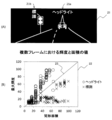
視線誘導標(デリニエータ)51(視線誘導標(デリニエータ)の例を示す図である図7に示す)などの小さな反射物(ヘッドライトと反射物との輝度と面積とを説明する図である図4の(A)の画像21の標識21b)は、光源領域42の矩形面積が小さく、図4の(B)に示す最大輝度分布22ではヘッドライト21a(図4の(A))やテールランプ(丸印)と標識(×印)とが重なる為、明るさと大きさの関係でヘッドライトやテールランプとそれら以外の標識とを完全に識別することができない。
しかし、対象物識別部の輝度の分散値の一例を示す図である
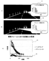
図5(A)、(B)、(C)に示すように、ヘッドライトやテールランプは自発光物の為、ヘッドライト輝度分布31に示すように、光源領域42内の明るさのばらつきが大きく、視線誘導標(デリニエータ)51は反射の為、デリエータ輝度分布32に示すように、明るさのばらつきが小さいという特徴がある。したがって、図5の(C)のグラフ33に示すように、分散値と距離との関係を示す光源領域42の明るさの分布を比較し、設定閾値34で分離する事で、視線誘導標(デリニエータ)51などの小さな反射物を、ヘッドライトやテールランプ以外と識別することができる。
図5(A)、(B)、(C)に示すように、ヘッドライトやテールランプは自発光物の為、ヘッドライト輝度分布31に示すように、光源領域42内の明るさのばらつきが大きく、視線誘導標(デリニエータ)51は反射の為、デリエータ輝度分布32に示すように、明るさのばらつきが小さいという特徴がある。したがって、図5の(C)のグラフ33に示すように、分散値と距離との関係を示す光源領域42の明るさの分布を比較し、設定閾値34で分離する事で、視線誘導標(デリニエータ)51などの小さな反射物を、ヘッドライトやテールランプ以外と識別することができる。
本実施例の画像処理装置1の中央処理装置3は、自車のヘッドライトの照射向きの情報を得る照射向き情報取得部17と、撮像装置11と、撮像装置11の撮像画像を取得する画像取得部12と、画像取得部12で取得した画像を複数の領域41に分割し、それぞれの画素領域41の輝度を計算する輝度計算部13と、輝度計算部13により計算された輝度が設定輝度以上となっている近接する複数の画素領域41を含む光源領域42として設定する光源領域設定部14と、光源領域設定部14により設定された複数の光源領域42と照射向き情報取得部17で取得したヘッドライトの照射向きとを基に光源領域42毎に閾値を決定する閾値決定部15と、複数の光源領域42のそれぞれの面積と、複数の光源領域42のそれぞれの画素領域41の輝度と、に基づいて光源領域42に位置する光源を閾値決定部15で決定した閾値を用いて対象物か反射物かを識別する。
自車のヘッドライトの照射向きの情報をもとに、閾値決定部15で光源領域ごとに閾値を変更することで、例えば、ヘッドライトの照射向きが変わったタイミングで現れた光源領域は厳しい閾値を、それ以外の光源領域は低い閾値を設定するなど、すべての光源領域を一定の閾値で識別するよりも、自由度の高い識別ができる。
その結果、光源と反射物とを識別が可能となる。また、変更した閾値を用いて対象物識別部16で光源領域の輝度と面積の関係を用いて識別を行うことで、対象物か、反射板かを識別することができる。
本実施例の画像処理装置1の中央処理装置3は、自車のヘッドライトの照射向きの情報を得る照射向き情報取得部17と、撮像装置11と、撮像装置11の撮像画像を取得する画像取得部12と、画像取得部12で取得した画像を複数の画素領域41に分割し、それぞれの画素領域41の輝度を計算する輝度計算部13と、輝度計算部13により計算された輝度が設定輝度以上となっている近接する複数の画素領域41を含む光源領域42として設定する光源領域設定部14と、光源領域設定部14により設定された複数の光源領域42と照射向き情報取得部17で取得したヘッドライトの照射向きとを基に光源領域42毎に閾値を決定する閾値決定部15と、光源領域設定部14により設定された光源領域42に含まれるそれぞれの画素領域41の輝度の分布、に基づいて光源領域42に位置する光源を閾値決定部15で決定した閾値を用いて対象物か反射物かを識別する。
自車のヘッドライトの照射向きの情報をもとに、閾値決定部15で光源領域ごとに閾値を変更することで、例えば、ヘッドライトの照射向きが変わったタイミングで現れた光源領域は厳しい閾値を、それ以外の光源領域は低い閾値を設定するなど、すべての光源領域を一定の閾値で識別するよりも、自由度の高い識別ができる。その結果、光源と反射を識別が可能となる。また、変更した閾値を用いて対象物識別部16で光源領域の輝度の分布を用いて識別を行うことで、対象物か、反射板かを識別することができる。
本実施例の画像処理装置1の中央処理装置3は、自車のヘッドライトの照射向きの情報を得る照射向き情報取得部17と、撮像装置11と、撮像装置11の撮像画像を取得する画像取得部12と、画像取得部12で取得した画像を複数の領域41に分割し、それぞれの画素領域41の輝度を計算する輝度計算部13と、輝度計算部13により計算された輝度が設定輝度以上となっている近接する複数の画素領域41を含む光源領域42として設定する光源領域設定部14と、光源領域設定部14により設定された複数の光源領域42と照射向き情報取得部17で取得したヘッドライトの照射向きとを基に光源領域42毎に閾値を決定する閾値決定部15と、複数の光源領域42のそれぞれの面積と、複数の光源領域42のそれぞれの画素領域41の輝度と、光源領域設定部14により設定された光源領域42に含まれるそれぞれの画素領域41の輝度の分布、に基づいて光源領域42に位置する光源を閾値決定部15で決定した閾値を用いて対象物か反射物かを識別する。
自車のヘッドライトの照射向きの情報をもとに、閾値決定部15で光源領域ごとに閾値を変更することで、例えば、ヘッドライトの照射向きが変わったタイミングで現れた光源領域は厳しい閾値を、それ以外の光源領域は低い閾値を設定するなど、すべての光源領域を一定の閾値で識別するよりも、自由度の高い識別ができ、その結果、光源と反射板とを識別が可能となる。また、変更した閾値を用いて対象物識別部16で光源領域の輝度と面積の関係、光源領域の輝度の分布を用いて識別を行うことで、対象物か、反射板かを識別することができる。
本実施例の画像処理装置1の中央処理装置3において、対象物識別部16は、複数の光源領域42のそれぞれの面積と、複数の光源領域42のそれぞれの画素領域41の輝度と、光源領域設定部14により設定された光源領域42に含まれるそれぞれの画素領域41の輝度の分布に基づいて光源領域42に位置する光源が対象物か反射物かを識別する。標識や看板などの反射物は、自車のヘッドライトの反射であるため、ヘッドライトやテールランプと比較して、画像上の明るさを表す輝度が低い傾向にある。そのため、同じ光源領域の矩形面積のヘッドライトと標識や看板は明るさの違いにより分離することが出来る。しかし、視線誘導標(デリニエータ)などの小さな反射物はヘッドライトよりも大きさが小さく、面積と明るさの関係では識別が困難である。そこで、光源領域の明るさのばらつきに着目し、自発光物であるヘッドライトやテールランプは、明るいところから暗いところまでのばらつきが大きく、反射物である視線誘導標(デリニエータ)はばらつきが小さい傾向にあり、明るさのばらつきを利用することで識別が可能である。そのため、面積と明るさの関係と、明るさのばらつきの関係の2つを組み合わせることで、標識や看板、視線誘導標(デリニエータ)の誤検知対策を行うことができる。
本実施例の画像処理装置1の中央処理装置3の対象物識別部16は、光源領域設定部14により設定された複数の光源領域42のそれぞれの面積に対する、複数の光源領域42のそれぞれの画素領域41の最大輝度の比が設定閾値23以上の場合に、光源領域42を対象物と判断する。
ヘッドライトやテールランプの明るさと大きさは基準が制定されており(道路運送車両の保安基準の細目を定める告示〈第二節〉第120条(前照灯等))、検知した距離によって画像上で一定の明るさと大きさで映る事が期待できる。そのため、画像上の明るさと大きさの比が一定値以上の場合に対象物と判断することができる。なお、設定閾値23(図4の(B))は最大輝度/矩形面積=1に限られず、例えば最大輝度/矩形面積=0.5としてもよい。
本実施例の画像処理装置1の中央処理装置3の対象物識別部16は、光源領域設定部14により設定された複数の光源領域42のそれぞれの面積に対する、複数の光源領域42のそれぞれの画素領域41の最大輝度の比が設定閾値23未満の場合に、光源領域42を反射物と判断する。
標識や看板などの反射物は自車のヘッドライトの反射である為、光源領域42の矩形面積が同じ場合で比較すると、画像上の明るさはヘッドライトよりも暗くなる。その為、明るさと大きさの比が設定閾値23未満の場合に、反射物と判断することができる。
本実施例の画像処理装置1の中央処理装置3の対象物識別部16は、光源領域設定部14により設定された光源領域42のそれぞれの画素領域41の輝度の分散値、または標準偏差値が設定閾値34以上の場合に、光源領域42を対象物と判断する。
ヘッドライトやテールランプは自発光物である為、視線誘導標(デリニエータ)51などの反射物と比較して光源領域内での明るさのばらつきが大きい(図5の(A)のヘッドライト輝度分布31参照)。そのため、明るさの分散値、または標準偏差が設定閾値34以上の場合に対象物と判断することができる。
本実施例の画像処理装置1の中央処理装置3の対象物識別部16は、光源領域設定部14により設定された光源領域42のそれぞれの画素領域41の輝度の分散値、または標準偏差が設定閾値34未満の場合に、光源領域42を反射物と判断する。
視線誘導標(デリニエータ)51などの反射物は、ヘッドライトに比べて光源領域内の明るさのばらつき(デリニエータ輝度分布32)が小さい。その為、明るさの分散値、または標準偏差が設定閾値34未満の場合に、反射物と識別することができる。
本実施例の配光制御システム100は、自車のヘッドライトの照射向きの情報を得る照射向き情報取得部17と、撮像装置11と、撮像装置11の撮像画像を取得する画像取得部12と、画像取得部12で取得した画像を複数の画素領域41に分割し、それぞれの画素領域41の輝度を計算する輝度計算部13と、輝度計算部13により計算された輝度が設定輝度以上となっている近接する複数の画素領域41を含む光源領域42として設定する光源領域設定部14と、光源領域設定部14により設定された複数の光源領域42と照射向き情報取得部17で取得したヘッドライトの照射向きとを基に光源領域42毎に閾値を決定する閾値決定部15と、複数の光源領域42のそれぞれの面積と、複数の光源領域42のそれぞれの画素領域41の輝度と、光源領域設定部14により設定された光源領域42に含まれるそれぞれの画素領域41の輝度の分布、に基づいて光源領域42に位置する光源を閾値決定部15で決定した閾値を用いて対象物を識別する対象物識別部16と、を備えた画像処理装置1と、対象物識別部16の識別結果に基づいて決定したヘッドランプの遮光領域に基づいて配光制御を行う配光制御部18を備える。
車両制御装置2における配光制御部18は、画像処理装置1の対象物識別部16の識別結果(車両検知結果)に基づいて、自車ヘッドライトの配光制御(配光制御アプリケーション)を実行する。配光制御としては、例えば、自車前方に先行車および対向車が存在しないときは自車ヘッドライトをハイビームに設定し、先行車または対向車が存在するときは自車ヘッドライトをロービームに設定するものがある。
また、自車前方に他車が検知された場合にはその他車が自車ヘッドライトの照射領域から除外されるように自車ヘッドライトの遮光領域を決定し、その遮光領域に基づいて自車ヘッドライトの配光制御を行うものがある。後者の場合、複数のヘッドライトの光軸を変化させるアクチュエータ(例えば複数のモータ)と、各ヘッドライトの光の一部を遮蔽するためのシェード機構が自車に設けられており、配光制御部18からはそれらに対する制御信号が出力される。
次に、図2は配光制御システム100による配光制御処理のフローチャートである。図2を参照して配光制御処理の流れを説明する。配光制御システム100(画像処理装置1及び車両制御装置2)は図2のフローチャートを所定の制御周期で繰り返し実行している。
図2において、処理を開始すると、画像取得部12は、ステップS11において、カメラ11に対して次に撮像する画像の露光時間を設定し、所定のタイミングで撮像を行ってカラー画像(撮像画像)を取得する。
次に、ステップS12において、輝度計算部13は、輝度計算式に従って輝度画像を生成する。
続いて、ステップS13において、光源領域設定部14は、ステップS12で生成した輝度画像に対し、一定の基準値以上の輝度画素(画素領域41)から構成される複数の車両候補領域(光源領域42)を計算する。
次に、ステップS14において、閾値決定部15は、ステップS13で計算した複数の車両候補領域(光源領域42)毎に、照射向き情報取得部17からの自車ヘッドライトの照射向き情報を基に閾値を決定する。
次に、ステップS15において、対象物識別部16は、ステップS13で計算した複数の車両候補領域(光源領域42)に対し、ステップS14で決定した閾値を基に、各領域が所定の対象物であるかどうかを判断する(対象物識別処理(車両識別処理))。
ここで、ステップ15における車両識別処理について、説明する。
図3は、本実施例における車両識別処理のフローチャートである。
図3において、対象物識別部16が車両識別処理を開始すると、ステップS21において、最大輝度が閾値以下か否かの判断を行うことにより、最大輝度によってフィルタ処理を行うかどうかの判断を行う。ステップS21で最大輝度が閾値以下でなければ、ステップS25に進み、最大輝度が閾値以下であれば、ステップS22に進む。
次に、ステップS22において、自車との距離が不正な値ではないか、車両候補領域のサイズ(大きさ)が一定以上あるか、距離と車両候補領域の大きさによって求めた実サイズが大きすぎないか、横位置が車線から離れすぎていないかなど閾値と比較することによりチェックし、問題無い場合に次のステップS23に進む。ステップS22において、問題がある場合は、ステップS26に進み、所定の対象物以外とする(誤検知対象として除外する)。
ステップS23では、車両候補領域の面積と最大輝度の比が閾値以上か否かを判断し、車両候補領域の面積と最大輝度の比が閾値以上の場合、所定の対象物であると判断し、次のS24ステップに進む。
ステップS23において、上述した比が閾値未満の場合、ステップS26に進み、所定の対象物以外として判断する。
ステップS24では、車両候補領域の輝度の分散値が閾値以上か否かを判断し、閾値以上の場合、所定の対象物であると判断し、次のステップS25に進む。ステップS24において、閾値未満34の場合、ステップS26に進み、所定の対象物外として判断する。
ステップS25において、ステップS22、S23、S24を通過した車両候補領域を検知対象としてグループとして保存する。
次に、ステップS27において、保存した車両候補領域の距離毎の輝度閾値により、閾値以上の車両候補領域を所定の対象物として識別する。
以上がステップ15における車両識別処理の説明である。
ステップS15で所定の対象物として判定した車両候補領域に対し、その領域を遮光対象とする旨の情報を付加し、配光制御部18へ出力する。また、ステップS15で所定の対象物ではないと判定した車両候補領域に対し、遮光対象ではない旨の情報を付加し、配光制御部18へ出力し、ステップS16に進む。
ステップS16において、配光制御部18は、対象物識別部16の出力情報に基づいて、自車ヘッドライトの遮光領域を決定し、その遮光領域が自車ヘッドライトの遮光領域から除外されるように自車ヘッドライトの配光制御を行う。
以上により、配光制御システム100による配光制御処理の1サイクルが完了する。配光制御システムは所定の制御周期だけ待機した後、ステップS11から一連の処理を再び実行する。
以上ように、本発明の一実施例によれば、自車のヘッドライトの照射向きが切り替わるタイミングで検知した光源領域に対し、閾値を変更することで、光源領域ごとに異なった閾値を設定する。例えば、ロービームからハイビームに切り替わったタイミングで検知した光源は反射物である可能性が高く、後段の識別処理で使用する閾値を厳しく設定することにより、ヘッドライトやテールランプと反射物を識別することができる。
また、光源領域毎に異なる閾値を設定することで、ヘッドライトやテールランプの未検知を抑制することができる。
また、識別処理において、ヘッドライトやテールランプは自発光しており、標識や看板などの反射物は自車のヘッドライトの反射である為、画像上の光源領域が同じ大きさの場合、ヘッドライトやテールランプの方が画像上で明るく映る。そのため、画像上の大きさと明るさの比によってヘッドライトやテールランプと反射物を分類することができる。
また、ヘッドライトやテールランプよりもサイズが小さく、大きさと明るさの比で分類することができない視線誘導標(デリニエータ)は、ヘッドライトやテールランプに比べ、画像上で明るさのばらつきが小さい。そのため、光源領域の明るさの分散値や標準偏差値を利用することでヘッドライトやテールランプとデリニエータを分類することができる。
なお、上述した例においては、閾値決定部15は、照射向き情報取得部17から供給される自車のヘッドランプの照射向き情報も考慮して、閾値を決定しているが、光源領域設定部14からの光源領域の情報のみで、閾値を決定することも可能である。
1・・・画像処理装置、2・・・車両制御装置、3・・・中央処理装置、4・・・記憶装置、11・・・カメラ(撮像装置)、12・・・画像取得部、13・・・輝度計算部、14・・・光源領域設定部、15・・・閾値決定部、16・・・対象物識別部、17・・・照射向き情報取得部、18・・・配光制御部、21・・・画像、21a・・・ヘッドライト、21b・・・標識、22・・・最大輝度分布、23、34・・・設定閾値、31・・・ヘッドライト輝度分布、32・・・デリニエータ輝度分布、41・・・画素領域、42・・・光源領域、51・・・視線誘導標(デリニエータ)、100・・・車両制御システム(配光制御システム)
Claims (10)
- 撮像装置により撮像された撮像画像を取得する画像取得部と、
前記画像取得部が取得した撮像画像を複数の画素領域に分割し、それぞれの画素領域の輝度を計算する輝度計算部と、
前記輝度計算部により計算された輝度が設定輝度以上となっている近接する複数の前記画素領域を含む領域を光源領域として設定する光源領域設定部と、
前記光源領域設定部により設定された複数の前記光源領域毎に閾値を決定する閾値決定部と、
前記閾値決定部で決定した前記閾値を用いて対象物を識別する対象物識別部と、を備えることを特徴とする画像処理装置。 - 請求項1に記載の画像処理装置において、
自車のヘッドランプの照射向きの情報を得る照射向き情報取得部を、さらに備え、前記照射向き情報取得部で取得した前記ヘッドランプの前記照射向きの情報に基づいて、前記閾値決定部は、前記光源領域設定部により設定された複数の前記光源領域毎に閾値を決定することを特徴とする画像処理装置。 - 請求項2に記載の画像処理装置において、
前記閾値決定部は、前記照射向きの情報に基づいて、前記ヘッドランプがロービームからハイビームに切り替わったことを検知し、前記光源領域設定部により設定された前記光源領域に対し、前記対象物識別部で対象物を識別するために用いられる前記閾値を前記光源領域毎に変更することを特徴とする画像処理装置。 - 請求項2に記載の画像処理装置において、
前記光源領域設定部は、前記光源領域の面積と、前記光源領域に含まれる複数の前記画素領域の中での最大輝度とを計算し、前記対象物識別部は、前記光源領域設定部により設定された前記光源領域を前記閾値決定部で決定した閾値を用いて、前記対象物か前記反射物かを識別することを特徴とする画像処理装置。 - 請求項2に記載の画像処理装置において、
前記光源領域設定部は、前記光源領域に含まれる複数の前記画素領域の輝度の分布を計算し、前記対象物識別部は、前記光源領域設定部により設定された前記光源領域を前記閾値決定部で決定した閾値を用いて、前記対象物か前記反射物かを識別することを特徴とする画像処理装置。 - 請求項4に記載の画像処理装置において、
前記光源領域設定部は、前記光源領域に含まれる複数の前記画素領域の輝度の分布を計算し、前記対象物識別部は、前記光源領域設定部により設定された前記光源領域を前記閾値決定部で決定した前記閾値を用いて、前記対象物か前記反射物かを識別することを特徴とする画像処理装置。 - 請求項4に記載の画像処理装置において、
前記対象物識別部は、前記光源領域設定部により設定された複数の前記光源領域のそれぞれの面積に対する、複数の前記光源領域に含まれるそれぞれの前記領域の最大輝度の比が設定閾値以上の場合に、前記光源領域を前記対象物と判断することを特徴とする画像処理装置。 - 請求項4に記載の画像処理装置において、
前記対象物識別部は、前記光源領域設定部により設定された複数の前記光源領域のそれぞれの面積に対する、複数の前記光源領域に含まれるそれぞれの前記領域の最大輝度の比が設定閾値未満の場合に、前記光源領域を前記反射物と判断することを特徴とする画像処理装置。 - 請求項5に記載の画像処理装置において、
前記対象物識別部は、前記光源領域設定部により設定された前記光源領域に含まれるそれぞれの前記領域の輝度の分散値または標準偏差値が、設定分散値または設定標準偏差値以上の場合に、前記光源領域に位置する前記光源を前記対象物と識別することを特徴とする画像処理装置。 - 請求項5に記載の画像処理装置において、
前記対象物識別部は、前記光源領域設定部により設定された前記光源領域に含まれるそれぞれの前記領域の輝度の分散値または標準偏差値が、設定分散値または設定標準偏差値未満の場合に、前記光源領域を前記反射物と判断することを特徴とする画像処理装置。
Priority Applications (2)
| Application Number | Priority Date | Filing Date | Title |
|---|---|---|---|
| CN201980083769.5A CN113196740B (zh) | 2018-12-18 | 2019-11-20 | 图像处理装置 |
| JP2020561236A JP7241772B2 (ja) | 2018-12-18 | 2019-11-20 | 画像処理装置 |
Applications Claiming Priority (2)
| Application Number | Priority Date | Filing Date | Title |
|---|---|---|---|
| JP2018-236751 | 2018-12-18 | ||
| JP2018236751 | 2018-12-18 |
Publications (1)
| Publication Number | Publication Date |
|---|---|
| WO2020129522A1 true WO2020129522A1 (ja) | 2020-06-25 |
Family
ID=71101259
Family Applications (1)
| Application Number | Title | Priority Date | Filing Date |
|---|---|---|---|
| PCT/JP2019/045357 Ceased WO2020129522A1 (ja) | 2018-12-18 | 2019-11-20 | 画像処理装置 |
Country Status (3)
| Country | Link |
|---|---|
| JP (1) | JP7241772B2 (ja) |
| CN (1) | CN113196740B (ja) |
| WO (1) | WO2020129522A1 (ja) |
Cited By (1)
| Publication number | Priority date | Publication date | Assignee | Title |
|---|---|---|---|---|
| JP7138265B1 (ja) * | 2021-06-17 | 2022-09-15 | ヌヴォトンテクノロジージャパン株式会社 | 物体検知装置、物体検知方法およびプログラム |
Families Citing this family (1)
| Publication number | Priority date | Publication date | Assignee | Title |
|---|---|---|---|---|
| CN113650553A (zh) * | 2021-09-17 | 2021-11-16 | 北京航空航天大学 | 一种汽车大灯智能调节控制装置及方法 |
Citations (2)
| Publication number | Priority date | Publication date | Assignee | Title |
|---|---|---|---|---|
| JP2002526317A (ja) * | 1998-09-18 | 2002-08-20 | ジェンテクス・コーポレーション | 連続可変ヘッドライトの制御 |
| JP2014231301A (ja) * | 2013-05-29 | 2014-12-11 | 富士重工業株式会社 | 画像処理装置 |
Family Cites Families (9)
| Publication number | Priority date | Publication date | Assignee | Title |
|---|---|---|---|---|
| JPS63184900A (ja) * | 1987-01-27 | 1988-07-30 | 松下電器産業株式会社 | 車両検出装置 |
| JP5353531B2 (ja) * | 2009-07-29 | 2013-11-27 | 株式会社豊田中央研究所 | 車両灯火認識装置及びプログラム |
| JP5617999B2 (ja) | 2011-04-13 | 2014-11-05 | トヨタ自動車株式会社 | 車載周辺物認識装置及びこれを用いる運転支援装置 |
| US10142595B2 (en) * | 2011-04-13 | 2018-11-27 | Nissan Motor Co., Ltd. | Driving assistance device and method of detecting vehicle adjacent thereto |
| DE102011085689A1 (de) * | 2011-11-03 | 2013-05-08 | Robert Bosch Gmbh | Verfahren und Vorrichtung zum Ermitteln einer Gruppe aus zumindest zwei benachbart angeordneten Beleuchtungseinheiten während der Fahrt eines Fahrzeugs |
| JP5820843B2 (ja) * | 2013-05-29 | 2015-11-24 | 富士重工業株式会社 | 周囲環境判定装置 |
| JP6034923B1 (ja) * | 2015-06-26 | 2016-11-30 | 富士重工業株式会社 | 車外環境認識装置 |
| JP6310899B2 (ja) * | 2015-11-25 | 2018-04-11 | 株式会社Subaru | 車外環境認識装置 |
| JP6200481B2 (ja) | 2015-11-25 | 2017-09-20 | 株式会社Subaru | 車外環境認識装置 |
-
2019
- 2019-11-20 JP JP2020561236A patent/JP7241772B2/ja active Active
- 2019-11-20 WO PCT/JP2019/045357 patent/WO2020129522A1/ja not_active Ceased
- 2019-11-20 CN CN201980083769.5A patent/CN113196740B/zh active Active
Patent Citations (2)
| Publication number | Priority date | Publication date | Assignee | Title |
|---|---|---|---|---|
| JP2002526317A (ja) * | 1998-09-18 | 2002-08-20 | ジェンテクス・コーポレーション | 連続可変ヘッドライトの制御 |
| JP2014231301A (ja) * | 2013-05-29 | 2014-12-11 | 富士重工業株式会社 | 画像処理装置 |
Cited By (2)
| Publication number | Priority date | Publication date | Assignee | Title |
|---|---|---|---|---|
| JP7138265B1 (ja) * | 2021-06-17 | 2022-09-15 | ヌヴォトンテクノロジージャパン株式会社 | 物体検知装置、物体検知方法およびプログラム |
| WO2022264894A1 (ja) * | 2021-06-17 | 2022-12-22 | ヌヴォトンテクノロジージャパン株式会社 | 物体検知装置、物体検知方法およびプログラム |
Also Published As
| Publication number | Publication date |
|---|---|
| JPWO2020129522A1 (ja) | 2021-10-07 |
| CN113196740B (zh) | 2023-07-04 |
| JP7241772B2 (ja) | 2023-03-17 |
| CN113196740A (zh) | 2021-07-30 |
Similar Documents
| Publication | Publication Date | Title |
|---|---|---|
| JP4853160B2 (ja) | 車両検出装置及びヘッドランプ制御装置 | |
| CN110160536B (zh) | 利用人行横道识别结果的引导信息提供装置及方法 | |
| US7566851B2 (en) | Headlight, taillight and streetlight detection | |
| US9904860B2 (en) | Vehicle exterior environment recognition apparatus | |
| US10037473B2 (en) | Vehicle exterior environment recognition apparatus | |
| US20170144585A1 (en) | Vehicle exterior environment recognition apparatus | |
| US20140098997A1 (en) | Method and device for detecting objects in the surroundings of a vehicle | |
| KR20210006276A (ko) | 플리커를 약화시키기 위한 이미지 처리 방법 | |
| US10121083B2 (en) | Vehicle exterior environment recognition apparatus | |
| RU2013132011A (ru) | Устройство помощи при вождении и способ обнаружения транспортного средства рядом с ним | |
| JP6420650B2 (ja) | 車外環境認識装置 | |
| KR101606476B1 (ko) | 카메라의 다중 노출 영상을 이용한 신호등 자동 인식 장치 및 방법 | |
| US20150054955A1 (en) | Image processing method of vehicle camera and image processing apparatus using the same | |
| O'malley et al. | Vision-based detection and tracking of vehicles to the rear with perspective correction in low-light conditions | |
| JP2012240530A (ja) | 画像処理装置 | |
| US20190045100A1 (en) | Image processing device, method, and program | |
| KR102089106B1 (ko) | 안개 발생 여부 판단 방법 및 이를 위한 장치 | |
| JP7241772B2 (ja) | 画像処理装置 | |
| JP6011173B2 (ja) | 瞳孔検出装置および瞳孔検出方法 | |
| KR102223324B1 (ko) | 평균 그레이스케일 비율에 기초한 차량 led 조명 상태 판단 방법 및 장치 | |
| CN113869292B (zh) | 用于自动驾驶的目标检测方法、装置及设备 | |
| KR101822302B1 (ko) | 차량의 헤드램프 제어 장치 및 이의 구동 방법 | |
| JP6816273B2 (ja) | 画像処理装置および配光制御システム | |
| KR102223320B1 (ko) | 인접 그레이스케일 비교에 기초한 차량 led 조명 상태 판단 방법 및 장치 | |
| EP3611655A1 (en) | Object detection based on analysis of a sequence of images |
Legal Events
| Date | Code | Title | Description |
|---|---|---|---|
| 121 | Ep: the epo has been informed by wipo that ep was designated in this application |
Ref document number: 19898303 Country of ref document: EP Kind code of ref document: A1 |
|
| ENP | Entry into the national phase |
Ref document number: 2020561236 Country of ref document: JP Kind code of ref document: A |
|
| NENP | Non-entry into the national phase |
Ref country code: DE |
|
| 122 | Ep: pct application non-entry in european phase |
Ref document number: 19898303 Country of ref document: EP Kind code of ref document: A1 |