WO2020129228A1 - Nœud sans fil et procédé de communication sans fil - Google Patents
Nœud sans fil et procédé de communication sans fil Download PDFInfo
- Publication number
- WO2020129228A1 WO2020129228A1 PCT/JP2018/047124 JP2018047124W WO2020129228A1 WO 2020129228 A1 WO2020129228 A1 WO 2020129228A1 JP 2018047124 W JP2018047124 W JP 2018047124W WO 2020129228 A1 WO2020129228 A1 WO 2020129228A1
- Authority
- WO
- WIPO (PCT)
- Prior art keywords
- iab node
- iab
- sttc
- ssb
- smtc
- Prior art date
Links
Images


Classifications
-
- H—ELECTRICITY
- H04—ELECTRIC COMMUNICATION TECHNIQUE
- H04W—WIRELESS COMMUNICATION NETWORKS
- H04W56/00—Synchronisation arrangements
- H04W56/001—Synchronization between nodes
-
- H—ELECTRICITY
- H04—ELECTRIC COMMUNICATION TECHNIQUE
- H04W—WIRELESS COMMUNICATION NETWORKS
- H04W56/00—Synchronisation arrangements
- H04W56/004—Synchronisation arrangements compensating for timing error of reception due to propagation delay
- H04W56/0045—Synchronisation arrangements compensating for timing error of reception due to propagation delay compensating for timing error by altering transmission time
-
- H—ELECTRICITY
- H04—ELECTRIC COMMUNICATION TECHNIQUE
- H04W—WIRELESS COMMUNICATION NETWORKS
- H04W48/00—Access restriction; Network selection; Access point selection
- H04W48/16—Discovering, processing access restriction or access information
Definitions
- the present disclosure relates to a wireless node and a wireless communication method.
- LTE Long Term Evolution
- UMTS Universal Mobile Telecommunication System
- a successor system to LTE is under study for the purpose of further widening the band and speeding up from LTE.
- LTE successor systems include, for example, LTE-Advanced (LTE-A), Future Radio Access (FRA), 5th generation mobile communication system (5G), 5Gplus (5G+), Radio Access Technology (New-RAT), New.
- LTE-A LTE-Advanced
- FAA Future Radio Access
- 5G 5th generation mobile communication system
- 5G+ 5th generation mobile communication system
- 5G+ 5th generation mobile communication system
- New-RAT Radio Access Technology
- NR Radio
- IAB integrated access and backhaul
- a wireless node such as an IAB node forms a wireless access link with a user terminal (User Equipment (UE)) and also forms a wireless backhaul link with another IAB node and/or a wireless base station.
- UE User Equipment
- 3GPPTR 38.874 1.0.0 “3rd Generation Generation Partnership Project;Technical Specification Specification Group RadioAccess Network;Study on Integrated IntegratedAccess and Backhaul; (Release 15),”December 2018 3GPP TSG RAN WG1 Meeting#95 R1-1813417 “Enhancements to support NR backhaul links,” Qualcomm Incorporated November 2018
- One aspect of the present disclosure is to provide a wireless node and a wireless communication method capable of appropriately discovering wireless nodes.
- a wireless node includes a receiving unit that receives setting information for at least one of transmission and measurement of a signal including information regarding synchronization, and a transmission unit that transmits the signal based on the setting information.
- a control unit that controls the timing of at least one of the measurements.
- FIG. 8 is a diagram illustrating an example of SMTC setting according to an aspect of the present disclosure.
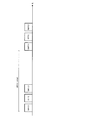
- FIG. 4 is a diagram showing an example of setting a STTC pattern according to an aspect of the present disclosure. It is a figure showing the 1st example of setting information for measurement concerning one mode of this indication.
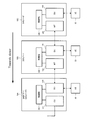
- FIG. 1 shows a configuration example of a wireless communication system according to an embodiment.
- the wireless communication system 1 includes a plurality of IAB nodes 10A to 10C that are examples of wireless nodes and a UE 20 that is an example of a user terminal.
- IAB nodes 10A to 10C are described without distinction, only common numbers among reference symbols may be used like “IAB node 10”.
- Each of the IAB nodes 10A to 10C is connected to another IAB node 10 by wireless communication.
- the IAB node 10B is connected to the IAB node 10A.
- the IAB node 10C is connected to the IAB node 10B.
- the upstream IAB node 10A from the IAB node 10B (that is, the direction closer to the IAB donor)
- the downstream IAB node 10B from the IAB node 10B that is, the direction away from the IAB donor
- 10C is called a child IAB node 10C.
- parent IAB node 10A indicates a parent IAB node for the IAB node 10B
- child IAB node 10C indicates a child IAB node for the IAB node 10B.
- the IAB node 10B corresponds to the child IAB node for the “parent IAB node 10A” and the parent IAB node for the “child IAB node 10C”.
- Each of the IAB nodes 10A to 10C forms a cell which is an area where wireless communication is possible. That is, the IAB node 10 has a function as a base station.
- the UE 20 in the cell can wirelessly connect to the IAB node 10 forming the cell.
- the IAB node 10A may be connected to the core network (CN) via the fiber backhaul (Fiber Backhaul (BH)).
- IAB node 10A may be referred to as an IAB donor.
- the number of IAB nodes 10 is three and the number of UEs 20 is one, but the number of IAB nodes 10 and the number of UEs 20 included in the wireless communication system 1 may be any number.
- the number of parent IAB nodes for one IAB node 10 may be two or more, and the number of child IAB nodes for one IAB node 10 may be two or more.
- -LP ,DL shows the Downlink (DL; Downlink) from the parent IAB node 10A with respect to the IAB node 10B.
- -LP ,UL shows Uplink (UL; Uplink) from the IAB node 10B to the parent IAB node 10A.
- L C,DL indicates the DL from the IAB node 10B to the child IAB node 10C.
- L C,UL indicates the UL from the child IAB node 10C for the IAB node 10B.
- ⁇ L A, DL indicates the DL from IAB node 10B to UE 20.
- ⁇ L A, UL represents a UL from UE20 for IAB node 10B.
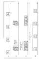
- FIG. 2 shows a configuration example of the IAB node 10.
- the IAB donor 10A has a control unit 100, a control unit (CU) 101, and a distributed unit (DU) 103.
- the IAB nodes 10B and 10C have a control unit 100, a Mobile-Termination (MT) 102, and a DU 103.
- the CU 101, MT 102, and DU 103 may be functional blocks.
- the function of the CU 101 when expressed, it may be expressed without a reference numeral like the CU.
- the function of the MT 102 when the function of the MT 102 is expressed, it may be expressed without a reference sign like MT, and when the function of the DU 103 is expressed, it may be expressed without a reference sign like DU.
- the DU 103 may have a function corresponding to a base station or an overhang station.
- an example of the MT 102 may have a function corresponding to a terminal.
- the IAB node 10B is connected to the upstream IAB node (IAB donor 10A in FIG. 2) by the MT 102. That is, the MT 102 of the IAB node 10B handles the connection with the parent IAB node 10A.
- the IAB node 10B is connected to the UE 20 and the MTs of the downstream IAB node 10C by the DU 103. That is, the DU 103 of the IAB node 10B processes the connection with the UE 20 and the child IAB node 10C.
- the connection of the UE 20 and/or the child IAB node 10C by the DU 103 is, for example, establishment of a Radio Resource Control (RRC) channel.
- RRC Radio Resource Control
- the control unit 100 controls the MT 102 (CU 101 in the case of the IAB donor 10A) and DU 103.
- the operation of the IAB node 10 described below may be realized by the control unit 100 controlling the MT 102 (CU 101 in the case of an IAB donor) and the DU 103.
- the control unit 100 may also include a storage unit for storing various types of information.
- the parent IAB node 10A indicates the next time resource for the link with the parent IAB node 10A (hereinafter referred to as “parent link”) from the viewpoint of the MT 102 of the IAB node 10B.
- DL time resource time resource used for DL
- UL time resource time resource used for UL
- FL -Flexible
- the IAB node 10B is a link between the IAB node 10B and the child IAB node 10C and/or a link between the IAB node 10B and the UE 20 (hereinafter, these links are referred to as “child links”).
- the “type” of the resource may be replaced with another term such as “use”, “type”, “type”, “category”, or “attribute” of the resource.
- the DL, UL and FL time resources of the DU's child links each belong to one of the following two categories: Hard: The corresponding time resource is always available for the DU's child links. • Soft: The availability of the corresponding time resource for the child link of the DU is explicitly and/or implicitly controlled by the parent IAB node 10A.
- 3PGG in the case where SSB is used for discovery and/or measurement between IAB nodes, it is considered to transmit and/or measure another SSB orthogonal to the SSB for UE (for example, orthogonal in TDM and/or FDM).
- SSB is used for discovery and/or measurement between IAB nodes
- it is considered to transmit and/or measure another SSB orthogonal to the SSB for UE (for example, orthogonal in TDM and/or FDM).
- TDM is an abbreviation for Time Division Multiplexing.
- FDM Frequency Division Multiplexing.
- the muting pattern is, for example, a pattern relating to the setting of the SSB measurement timing and/or the transmission timing. That is, muting may mean that SSB measurement and/or measurement is not performed. The details of the muting pattern will be described later.
- the IAB node may support SSB-based and/or CSI-RS-based solutions for the measurement of RSRP/RSRQ RRM of the wireless backhaul link.
- RSRP is an abbreviation for Reference Signal Received Power.
- RSRP is an abbreviation for Reference Signal Received Quality.
- CSI-RS is an abbreviation for Channel State Information Reference Signal.
- stage 2 In the discovery process between IAB nodes for the purpose of discovering IAB nodes and IAB donors after the DU of the IAB node becomes active (hereinafter referred to as “stage 2”), IAB nodes and half-duplex in a multi-hop topology are used. It is necessary to consider communication restrictions.
- the IAB node may support the following (A1) and (A2) in an SSB-based solution.
- IAB nodes may reuse the same set of SSBs used for access UEs.
- the access UE is a UE that accesses the IAB node.
- the SSB for cell search between the IAB nodes in the stage 2 is arranged on the currently defined sync raster in the standalone (SA) frequency layer.
- SA standalone
- NSA Non Standalone
- the SSB for cell search is transmitted in the SMTC set for the access UE.
- the synchronous raster may be a frequency that the UE searches for during initial access.
- IAB nodes may use SSB orthogonal to SSB used for access UEs (eg, orthogonal in TDM and/or FDM).
- the SSB for cell search and measurement between IAB nodes in stage 2 may be muted and is not on the currently defined synchronous raster in the SA frequency layer.
- the orthogonal SSB is transmitted by an SMTC different from the SMTC set for the access UE.
- the IAB node when performing cell search between IAB nodes in stage 2, the IAB node does not have to be muted for SSB transmission targeted for UE cell search and measurement. This means that in the SA frequency layer, the SSB transmitted in the currently defined synchronous raster follows the period defined for initial access. Also, in the case of (A2) above, this means that the SSB for stage 2 cell search between IAB nodes may be muted, and at least the SSB used for UE cell search and measurement. Implies TDM with.
- Non-Patent Document 2 proposes the following in order to increase the flexibility of the setting related to the discovery and/or measurement of IAB nodes.
- -The SMTC for discovering IAB nodes supports a period longer than the maximum period of 160 ms, which is the maximum period of the SMTC for access UE. Increase the maximum number of SMTC windows that can be set per frequency above two.
- STTC SSB transmission timing setting
- an SMTC timing for SSB measurement and an STTC timing for SSB transmission may be included in the SMTC cycle.
- the IAB node 10 may measure the SSB transmitted from the peripheral IAB node at the SMTC timing and transmit the SSB to the peripheral IAB node at the STTC timing.
- each of the three IAB nodes 10 may be set with a UE-oriented SMTC timing (“UE-SMTC” in FIG. 4 ).
- the three IAB nodes transmit the SSB towards the UE 20 in the UE-SMTC.
- SMTC timing for the IAB nodes (“IAB-SMTC” in FIG. 4) may be set to each of the three IAB nodes 10.
- the IAB-SMTCs set in each IAB node 10 are orthogonal to each other.
- the IAB-SMTC is orthogonal to the UE-SMTC.
- IAB-SMTCs may have different SSB index patterns.
- the first IAB-SMTC may be SSB indexes #1 to #3
- the second IAB-SMTC may be SSB indexes #4 to #6
- the third IAB-SMTC may be SSB indexes #7 to #9. ..
- the IAB-SMTCs may have different window timings. Further, as shown in FIGS. 4C and 4D, the IAB-SMTCs may have different window timings. Further, the IAB-SMTCs may be continuous as shown in FIG. 4(c) or may be discontinuous as shown in FIG. 4(d).
- the difference in the hatching patterns of IAB-SMTC shown in FIGS. 4(b), 4(c) and 4(d) above represents the difference in STTC patterns.
- a first STBC pattern having horizontal stripes is set to the first IAB node
- a second STTC pattern having diagonal lines is set to the second IAB node
- a vertical ST stripe pattern is set to the third IAB node.
- the third STTC pattern is set.
- the horizontal striped IAB-SMTC may be used by the first IAB node as STTC (ie transmitting SSB) and by the second and third IAB nodes as SMTC (ie measuring SSB).
- the shaded IAB-SMTC may be used by the second IAB node as STTC (that is, SSB is transmitted), and the first and third IAB nodes may be used as SMTC (that is, SSB is measured).
- the vertically striped IAB-SMTC may be used by the third IAB node as STTC (that is, SSB is transmitted), and the first and second IAB nodes may be used as SMTC (that is, SSB is measured).
- the IAB node transmits the SSB at the timing or cycle set as STTC, and the SSB from the surrounding IAB nodes at the timing or cycle set as SMTC. Is assumed to be detected and measured.
- the IAB nodes with the common STTC timing cannot detect and measure the IAB nodes due to the limitation of half-duplex communication. That is, since the IAB nodes to which the common STTC timing is set transmit the SSB at the common STTC timing, they cannot receive the SSB of the other party at this timing.
- the above avoidance method is, for example, every time a new IAB node is added, or every time the STTC pattern of an IAB node under another CU is updated, the STTC setting of each IAB node is reviewed, or Changes can be involved.
- Example 1 Example 2 and Example 3 will be described.
- the examples 1, 2, and 3 may be implemented in combination with each other, or may be implemented by switching between them.
- Example 1 In the IAB node 10, more than two SMTCs can be set per frequency.
- the setting information “MeasObject” for measurement illustrated in FIGS. 6A and 6B is partially modified for the purpose of enabling setting of a plurality of SSB-MTCs (that is, SMTCs) in a list format.
- the maximum number (upper limit) of SMTC that can be set may be specified by the specifications.
- the maximum number (upper limit) of the number of SMTCs that can be set may be reported from the IAB node 10 as capability information (Capability).
- FIG. 7A and 7B are diagrams illustrating an example of the setting information for measurement according to the first example.
- the setting information for measurement “MeasObjectNR” is a parameter for designating the number of SSB-MTCs to be released and a parameter for designating the number of SSB-MTCs to be added or modified. May have.
- the parameter for designating the number of SSB-MTCs to be released will be referred to as “smtcToReleaseList” for convenience, but is not limited to this name.
- the parameter for designating the number of SSB-MTCs to be added or modified is referred to as “smtcToAddModList” for convenience, but is not limited to this name.
- the setting information “SSB-MTC” for SSB-MTC may have a parameter for identifying the SSB-MTC.
- the parameter is referred to as “SSB-MTC-ID” for convenience, but the name is not particularly limited to this.
- the setting information “SSB-MTC” has a parameter “sf320” for designating a 320 ms cycle and/or a parameter “sf640” for designating a 640 ms cycle as options for setting the SMTC cycle. Good.
- the above parameter “SSB-MTC-ID” may be a value from 0 to (“maxNrofSSB-MTCs”-1).
- “maxNrofSSB-MTCs” is the maximum number of SSB-MTCs that can be set.
- the IAB node 10 may determine “maxNrofSSB-MTCs” based on a predetermined value (eg, “8”) defined in the specifications.
- the IAB node 10B may determine “maxNrofSSB-MTCs” based on the number of configurable SSB-MTCs reported from the MT of the child IAB node 10C as capability information (Capability).
- Capability capability information
- the parameter indicating the maximum number of SSB-MTCs that can be set is referred to as “maxNrofSSB-MTCs” for convenience, but is not limited to this name.
- the IAB node 10B may explicitly specify, for the child IAB node 10C, at least one SMTC to be used as STTC among the plurality of set SMTCs.
- the plurality of SMTCs may be set by the setting information described in Example 1 above.
- an ID (“SSB-MTC-ID” in FIG. 7B) may be given to each SSB-MTC, and the IAB node 10B may specify the SMTC used as the STTC by using the SSB-MTC-ID.
- SSB-MTC-ID may be expressed as "SMTC-ID".
- FIG. 8 shows an example of parameters for designating SSB-TTC (STTC) using SSB-MTC-ID.
- the SMTC may be notified as a setting for MT of the IAB node 10 and the STTC may be notified as a setting for DU of the IAB node 10. That is, the SMTC setting and the STTC setting may be notified by different information elements (Information Elements). Alternatively, STTC may be designated in the setting information “MeasObject” for setting SMTC.
- the child IAB node 10C autonomously selects any one of the set SMTCs (SSB-MTCs) as the STTC. Good. For example, the child IAB node 10C may measure at each SMTC and select the SMTC with the lowest detection level as the STTC. As a result, the child IAB node 10C can select, as the STTC, the SMTC that is highly likely not to be used as the STTC by the peripheral IAB nodes. Further, in this case, the child IAB node 10C may include the SMTC-ID selected for STTC in the measurement result report (Measurement Report (MR)).
- MR Measurement Report
- the STTC autonomously selected by the child IAB node 10C is There is a high possibility that it will be common to the STTC selected by the peripheral IAB node 10. Therefore, in this case, the NW (Network) (or the CU of the IAB donor 10A) may reset the STTC different from the STTC included in the MR from the child IAB node 10C to the child IAB node 10C.
- the DU of the child IAB node 10C may recognize that, if STTC is not designated, the SSB is not transmitted for the discovery between the IAB nodes.
- the IAB node 10 that can only be a child IAB node (or cannot be a parent IAB node) may recognize that STB is not transmitted for discovery between IAB nodes when STTC is not instructed.
- “recognition” may be replaced with another term such as “assumed”, “decision” or “judgment”.
- “designation” may be replaced with another term such as “instruction”, “notification”, or “setting”.
- the child IAB node 10C When the STTC is not designated, the child IAB node 10C performs the above-mentioned processing of recognizing that STTC is autonomously selected and the processing of recognizing that SSB is not transmitted for the discovery of IAB nodes. The switching may be performed based on whether or not the parent IAB node has the capability (Capability).
- the IAB node 10 may separately have an STTC for UE (hereinafter referred to as “UE-STTC”) and an STTC for discovery between IAB nodes (hereinafter referred to as “IAB-STTC”) as STTC. Then, among these STTCs, at least in IAB-STTC, any of the set SMTCs may be used as the STTC.
- the STTC may be specified by the SMTC-ID, as in Example 2-1 above. Alternatively, the STTC may be designated by the SSB transmission timing setting for setting the STTC without using the SMTC-ID.
- UE-STTC and IAB-STTC may be designated from the set SMTC, respectively.
- the SSB transmission frequency may be set for each of the UE-STTC and IAB-STTC. That is, UE-STTC and IAB-STTC may have different frequency positions for SSB transmission.
- IAB-STTC may be specified from the set SMTC, and UE-STTC may be set separately.
- the SSB transmission frequency may be set for each of the UE-STTC and IAB-STTC. That is, UE-STTC and IAB-STTC may have different frequency positions for SSB transmission.
- a muting pattern for STTC can be set in the IAB node 10. That is, the IAB node 10 may support aperiodic STTC. For example, the IAB node 10 may stop SSB transmission at some timings, cycles, or periods set as the STTC pattern, and may measure peripheral IAB nodes to which the same STTC pattern is applied.
- a muting pattern for SMTC can be set in the IAB node 10. That is, the IAB node 10 may support aperiodic SMTC. For example, the IAB node 10 may stop SSB measurement at some timings, cycles, or periods set as the SMTC pattern and enable SSB transmission to the peripheral IAB nodes to which the common SMTC pattern is applied.
- Example 3-1 Example 3-1
- Example 3-2 Example 3-1
- Example 3-1>> The above-described STTC muting cycle and offset may be set, for example, by the setting information shown in FIG. 9.
- the setting information for the cycle and offset for muting STTC will be referred to as “PeriodicityAndOffsetSTTCMuting” for convenience, but the name is not limited to this.
- the setting information “PeriodicityAndOffsetSTTCMuting” may have a parameter for selecting the STTC muting pattern.
- the parameter “sttc2” is a parameter for setting the muted STTC of the two STTCs.
- the parameter “sttc4” is a parameter for setting the muted STTC among the four STTCs. For example, when the parameter “sttc4” is “2”, the third STTC among the four STTCs is muted as shown in FIG.
- the setting information of the above-described SMTC muting cycle and offset may be the same as in FIG. 9.
- the STTC muting pattern corresponding to the cell ID may be specified in the specifications.
- the muting pattern of the SMTC according to the cell ID may be specified in the specifications.
- the IAB node 10 performing the measurement can recognize the muting pattern set in each peripheral IAB node. Therefore, the IAB node 10 that performs measurement can perform processing such as synthetic reception and/or averaging in measurement in a deterministic or deterministic manner.
- ⁇ Measurement may not be performed at the SMTC selected for STTC.
- a looser performance specification for example, measurement accuracy
- that of the measurement by another SMTC may be applied.
- the IAB node 10 may recognize that the measurement may be performed at the SMTC selected for STTC. Further, when the muting pattern for STTC (or SMTC) is not set, the IAB node 10 may recognize that it is not necessary to perform measurement at the SMTC selected as STTC.
- the IAB node 10 may be instructed by the information element different from the muting pattern whether or not to perform the measurement. Further, in the case where the muting pattern is not explicitly designated as in the above-mentioned Example 3-2, this explicit instruction may be given.
- -Whether or not to perform measurement at the SMTC selected as STTC may depend on the implementation of the IAB node. For example, an IAB node that does not have the constraint of half-duplex communication makes a measurement at the SMTC selected as STTC, and an IAB node that has the constraint of half-duplex communication makes a measurement at the SMTC selected as STTC. Good.
- the SSB transmission timing configuration may be set for the DU.
- the SSB transmission timing setting for the access UE for example, STTC1 or UE-STTC
- the SSB transmission timing setting for the peripheral IAB node for example, STTC2 or IAB-STTC
- Each STTC may include at least one of the following. • SSB transmission cycle and timing offset • SSB transmission frequency • SSB transmission index bitmap
- any value of 5, 10, 20, 40, 80, and 160 ms can be set in the STTC for UE, similarly to the candidate value of the SMTC cycle, and in the STTC for IAB, , A value longer than 160 ms may be settable.
- an offset value may be set with a granularity of 1 ms as in the case of SMTC or a granularity of 5 ms.
- the SSB measurement timing configuration (configuration) may be set for MT.
- the SSB measurement timing setting (for example, SMTC1, STMC2, SMTC3,...)
- Corresponding to the SSB transmission timing of each peripheral IAB node may be set for MT.
- the SSB transmission timing setting (STTC1 or UE-STTC) for the access UE and the SSB transmission timing setting (STTC2 or IAB-STTC) for the peripheral IAB nodes are the SSB transmission frequency in addition to the timing or the cycle. May be different from each other.
- the DU of the IAB node may determine the transmission SSB index without specifying the transmission SSB index. Also, the DU of the IAB node 10B may report the number of transmission SSBs as capability information (capability) to the parent IAB node 10A, and the parent IAB node 10A may specify the transmission SSB index to the IAB node 10B by STTC. ..
- the names of the above setting information and parameters are examples. That is, the names of the setting information and the parameters of the present disclosure may be different from the above.
- a wireless node (IAB node) according to the present disclosure, a receiving unit that receives setting information for SSB transmission and/or measurement, and control that uses at least one of a plurality of SMTCs as STTC based on the setting information. And a control unit for performing.
- the setting information may include an SMTC-ID for identifying each SMTC. Further, the SMTC used as the STTC may be designated using this SMTC-ID.
- each wireless node can autonomously set an appropriate SMTC and/or STTC.
- each functional block may be realized by using one device physically or logically coupled, or directly or indirectly (for example, two or more devices physically or logically separated). , Wired, wireless, etc.) and may be implemented using these multiple devices.
- the functional blocks may be realized by combining the one device or the plurality of devices with software.
- Functions include judgment, decision, judgment, calculation, calculation, processing, derivation, investigation, search, confirmation, reception, transmission, output, access, resolution, selection, selection, establishment, comparison, assumption, expectation, observation, Broadcasting, notifying, communicating, communicating, forwarding, configuration, reconfiguring, allocating, mapping, assigning, etc., but not limited to these.
- a functional block (component) that functions transmission is called a transmitter (transmitting unit) or a transmitter (transmitter).
- the implementation method is not particularly limited.
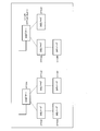
- FIG. 11 is a diagram illustrating an example of a hardware configuration of an IAB node and a user terminal according to an embodiment of the present disclosure.
- the IAB node 10 and the user terminal 20 described above may be physically configured as a computer device including a processor 1001, a memory 1002, a storage 1003, a communication device 1004, an input device 1005, an output device 1006, a bus 1007, and the like. ..
- the word “device” can be read as a circuit, device, unit, or the like.
- the hardware configurations of the IAB node 10 and the user terminal 20 may be configured to include one or a plurality of each device illustrated in the figure, or may be configured not to include some devices.
- Each function in the IAB node 10 and the user terminal 20 causes a predetermined software (program) to be loaded onto hardware such as the processor 1001 and the memory 1002, so that the processor 1001 performs an arithmetic operation and controls communication by the communication device 1004. Or controlling at least one of reading and writing of data in the memory 1002 and the storage 1003.
- a predetermined software program
- the processor 1001 performs an arithmetic operation and controls communication by the communication device 1004.
- the processor 1001 operates an operating system to control the entire computer, for example.
- the processor 1001 may be configured by a central processing unit (CPU) including an interface with peripheral devices, a control device, an arithmetic device, a register, and the like.
- CPU central processing unit
- the control unit 100 and the like described above may be realized by the processor 1001.
- the processor 1001 reads a program (program code), software module, data, and the like from at least one of the storage 1003 and the communication device 1004 into the memory 1002, and executes various processes according to these.
- a program program that causes a computer to execute at least part of the operations described in the above-described embodiments is used.
- the control unit 100 of the IAB node 10 may be implemented by a control program stored in the memory 1002 and operating in the processor 1001, and may be implemented similarly for other functional blocks.
- the various processes described above are executed by one processor 1001, they may be executed simultaneously or sequentially by two or more processors 1001.
- the processor 1001 may be implemented by one or more chips.
- the program may be transmitted from the network via an electric communication line.
- the memory 1002 is a computer-readable recording medium, and is configured by, for example, at least one of ROM (Read Only Memory), EPROM (Erasable Programmable ROM), EEPROM (Electrically Erasable Programmable ROM), RAM (Random Access Memory), and the like. May be done.
- the memory 1002 may be called a register, a cache, a main memory (main storage device), or the like.
- the memory 1002 can store an executable program (program code), a software module, or the like for implementing the wireless communication method according to the embodiment of the present disclosure.
- the storage 1003 is a computer-readable recording medium, for example, an optical disc such as a CD-ROM (Compact Disc ROM), a hard disc drive, a flexible disc, a magneto-optical disc (for example, a compact disc, a digital versatile disc, a Blu-ray disc). At least one of a (registered trademark) disk, a smart card, a flash memory (for example, a card, a stick, and a key drive), a floppy (registered trademark) disk, a magnetic strip, or the like may be used.
- the storage 1003 may be called an auxiliary storage device.
- the storage medium described above may be, for example, a database including at least one of the memory 1002 and the storage 1003, a server, or another appropriate medium.
- the communication device 1004 is hardware (transmission/reception device) for performing communication between computers via at least one of a wired network and a wireless network, and is also called, for example, a network device, a network controller, a network card, a communication module, or the like.
- the communication device 1004 includes, for example, a high frequency switch, a duplexer, a filter, a frequency synthesizer, and the like in order to realize at least one of frequency division duplex (FDD: Frequency Division Duplex) and time division duplex (TDD: Time Division Duplex). May be composed of For example, the antennas of the base station and the terminal may be realized by the communication device 1004.
- the transmitter/receiver may be implemented by physically or logically separating the transmitter and the receiver.
- the input device 1005 is an input device (eg, keyboard, mouse, microphone, switch, button, sensor, etc.) that receives an input from the outside.
- the output device 1006 is an output device (for example, a display, a speaker, an LED lamp, etc.) that performs output to the outside. Note that the input device 1005 and the output device 1006 may be integrated (for example, a touch panel).
- Each device such as the processor 1001 and the memory 1002 is connected by a bus 1007 for communicating information.
- the bus 1007 may be configured by using a single bus, or may be configured by using a different bus for each device.
- the IAB node 10 and the user terminal 20 are hardware such as a microprocessor, a digital signal processor (DSP), an ASIC (Application Specific Integrated Circuit), a PLD (Programmable Logic Device), and an FPGA (Field Programmable Gate Array). It may be configured to include hardware, and a part or all of each functional block may be realized by the hardware. For example, the processor 1001 may be implemented using at least one of these hardware.
- DSP digital signal processor
- ASIC Application Specific Integrated Circuit
- PLD Programmable Logic Device
- FPGA Field Programmable Gate Array
- the notification of information is not limited to the aspect/embodiment described in the present disclosure, and may be performed using another method.
- the notification of information includes physical layer signaling (for example, DCI (Downlink Control Information), UCI (Uplink Control Information)), upper layer signaling (for example, RRC (Radio Resource Control) signaling, MAC (Medium Access Control) signaling, It may be implemented by notification information (MIB (Master Information Block), SIB (System Information Block)), another signal, or a combination thereof.
- the RRC signaling may be referred to as an RRC message, and may be, for example, an RRC connection setup (RRC Connection Setup) message, an RRC connection reconfiguration message, or the like.
- Each aspect/embodiment described in the present disclosure includes LTE (Long Term Evolution), LTE-A (LTE-Advanced), SUPER 3G, IMT-Advanced, 4G (4th generation mobile communication system), and 5G (5th generation mobile communication).
- system FRA (Future Radio Access), NR (new Radio), W-CDMA (registered trademark), GSM (registered trademark), CDMA2000, UMB (Ultra Mobile Broadband), IEEE 802.11 (Wi-Fi (registered trademark) )), IEEE 802.16 (WiMAX (registered trademark)), IEEE 802.20, UWB (Ultra-WideBand), Bluetooth (registered trademark), systems using other suitable systems, and extensions based on these. It may be applied to at least one of the next-generation systems. Further, a plurality of systems may be combined and applied (for example, a combination of at least one of LTE and LTE-A with 5G).
- the specific operation performed by the base station in the present disclosure may be performed by its upper node in some cases.
- the various operations performed for communication with a terminal are the base station and other network nodes than the base station (eg MME or S-GW and the like are conceivable, but are not limited thereto, and it is clear that at least one of them can be used.
- MME or S-GW network nodes
- a combination of a plurality of other network nodes for example, MME and S-GW may be used.
- Information and the like can be output from the upper layer (or lower layer) to the lower layer (or upper layer). Input/output may be performed via a plurality of network nodes.
- the input/output information and the like may be stored in a specific place (for example, a memory) or may be managed using a management table. Information that is input/output may be overwritten, updated, or added. The output information and the like may be deleted. The input information and the like may be transmitted to another device.
- the determination may be performed based on a value represented by 1 bit (whether 0 or 1), may be performed based on a Boolean value (Boolean: true or false), or may be compared by a numerical value (for example, a predetermined value). (Comparison with a value).
- the notification of the predetermined information (for example, the notification of “being X”) is not limited to the explicit notification, and is performed implicitly (for example, the notification of the predetermined information is not performed). Good.
- software, instructions, information, etc. may be sent and received via a transmission medium.
- the software uses a website using at least one of wired technology (coaxial cable, optical fiber cable, twisted pair, digital subscriber line (DSL), etc.) and wireless technology (infrared, microwave, etc.), When sent from a server, or other remote source, at least one of these wired and wireless technologies are included within the definition of transmission medium.
- wired technology coaxial cable, optical fiber cable, twisted pair, digital subscriber line (DSL), etc.
- wireless technology infrared, microwave, etc.
- At least one of the channel and the symbol may be a signal (signaling).
- the signal may also be a message.
- a component carrier CC:Component Carrier
- CC Component Carrier
- the information, parameters, etc. described in the present disclosure may be represented by using an absolute value, may be represented by using a relative value from a predetermined value, or by using other corresponding information. May be represented.
- the radio resources may be those indicated by the index.
- Base station In the present disclosure, “base station (BS)”, “radio base station”, “fixed station”, “NodeB”, “eNodeB (eNB)”, “gNodeB (gNB)”, “"Accesspoint”,”transmissionpoint”,”receptionpoint”,”transmission/receptionpoint”,”cell”,”sector”,”cellgroup”,” The terms “carrier”, “component carrier” and the like may be used interchangeably.
- a base station may be referred to by terms such as macro cell, small cell, femto cell, and pico cell.
- a base station can accommodate one or more (eg, three) cells.
- the entire coverage area of the base station can be divided into multiple smaller areas, each smaller area being a base station subsystem (eg, a small indoor base station (RRH: Communication service can also be provided by Remote Radio Head.
- RRH small indoor base station
- the term "cell” or “sector” means a part or the whole of the coverage area of at least one of the base station and the base station subsystem that perform communication service in this coverage. Refers to.
- MS mobile station
- UE user equipment
- terminal terminal
- Mobile stations are defined by those skilled in the art as subscriber stations, mobile units, subscriber units, wireless units, remote units, mobile devices, wireless devices, wireless communication devices, remote devices, mobile subscriber stations, access terminals, mobile terminals, wireless. It may also be referred to as a terminal, remote terminal, handset, user agent, mobile client, client, or some other suitable term.
- At least one of the base station and the mobile station may be called a transmission device, a reception device, a communication device, or the like.
- the base station and the mobile station may be a device mounted on the mobile body, the mobile body itself, or the like.
- the moving body may be a vehicle (eg, car, airplane, etc.), an unmanned moving body (eg, drone, self-driving car, etc.), or a robot (manned or unmanned).
- At least one of the base station and the mobile station also includes a device that does not necessarily move during a communication operation.
- at least one of the base station and the mobile station may be an IoT (Internet of Things) device such as a sensor.
- IoT Internet of Things
- the base station in the present disclosure may be replaced by the user terminal.
- the communication between the base station and the user terminal is replaced with communication between a plurality of user terminals (eg, may be called D2D (Device-to-Device), V2X (Vehicle-to-Everything), etc.).
- the user terminal 20 may have the function of the above-described base station 10.
- the wording such as “up” and “down” may be replaced with the wording (eg, “side”) corresponding to the communication between terminals.
- the uplink channel and the downlink channel may be replaced with the side channel.
- the user terminal in the present disclosure may be replaced by the base station.
- the base station 10 may have the function of the user terminal 20 described above.
- determining and “determining” as used in this disclosure may encompass a wide variety of actions.
- “Judgment” and “decision” are, for example, judgment, calculating, computing, processing, deriving, investigating, and looking up, search, inquiry. (Eg, searching in a table, database, or another data structure), ascertaining what is "determined” and “determined” may be included.
- “decision” and “decision” include receiving (eg, receiving information), transmitting (eg, transmitting information), input, output, and access. (Accessing) (for example, accessing data in a memory) may be regarded as “judgment” and “decision”.
- judgment and “decision” means to consider that “resolving”, “selecting”, “choosing”, “establishing”, “comparing”, etc. May be included. That is, the “judgment” and “decision” may include considering some action as “judgment” and “decision”. In addition, “determination (decision)” may be read as “assuming", “expecting”, “considering”, and the like.
- connection means any direct or indirect connection or coupling between two or more elements, and It can include the presence of one or more intermediate elements between two elements that are “connected” or “coupled”.
- the connections or connections between the elements may be physical, logical, or a combination thereof.
- connection may be read as “access”.
- two elements are in the radio frequency domain, with at least one of one or more wires, cables and printed electrical connections, and as some non-limiting and non-exhaustive examples. , Can be considered to be “connected” or “coupled” to each other, such as with electromagnetic energy having wavelengths in the microwave region and the light (both visible and invisible) region.
- the reference signal may be abbreviated as RS (Reference Signal), and may be referred to as a pilot (Pilot) depending on the applied standard.
- RS Reference Signal
- Pilot pilot
- a radio frame may be composed of one or more frames in the time domain. Each frame or frames in the time domain may be referred to as a subframe.
- a subframe may be further composed of one or more slots in the time domain.
- the subframe may have a fixed time length (for example, 1 ms) that does not depend on the numerology.
- Numerology may be a communication parameter applied to at least one of transmission and reception of a signal or channel.
- Numerology includes, for example, subcarrier spacing (SCS: SubCarrier Spacing), bandwidth, symbol length, cyclic prefix length, transmission time interval (TTI: Transmission Time Interval), number of symbols per TTI, radio frame configuration, transmission/reception
- SCS subcarrier spacing
- TTI Transmission Time Interval
- At least one of a specific filtering process performed by the device in the frequency domain and a specific windowing process performed by the transceiver in the time domain may be indicated.
- a slot may be composed of one or more symbols (OFDM (Orthogonal Frequency Division Multiplexing) symbol, SC-FDMA (Single Carrier Frequency Division Multiple Access) symbol, etc.) in the time domain.
- a slot may be a time unit based on numerology.
- a slot may include multiple minislots. Each minislot may be composed of one or more symbols in the time domain. The minislot may also be called a subslot. Minislots may be configured with a smaller number of symbols than slots.
- a PDSCH (or PUSCH) transmitted in a time unit larger than a minislot may be referred to as PDSCH (or PUSCH) mapping type A.
- the PDSCH (or PUSCH) transmitted using the minislot may be referred to as PDSCH (or PUSCH) mapping type B.
- Radio frame, subframe, slot, minislot, and symbol all represent the time unit when transmitting a signal. Radio frames, subframes, slots, minislots, and symbols may have different names corresponding to them.
- one subframe may be called a transmission time interval (TTI)
- TTI transmission time interval
- TTI transmission time interval
- TTI transmission time interval
- TTI transmission time interval
- TTI means, for example, a minimum time unit of scheduling in wireless communication.
- the base station performs scheduling for allocating radio resources (frequency bandwidth that can be used in each user terminal, transmission power, etc.) to each user terminal in units of TTI.
- the definition of TTI is not limited to this.
- the TTI may be a transmission time unit of a channel-encoded data packet (transport block), code block, codeword, or the like, or may be a processing unit of scheduling, link adaptation, or the like.
- the time interval eg, the number of symbols
- the transport block, code block, codeword, etc. may be shorter than the TTI.
- one slot or one minislot is called a TTI
- one or more TTIs may be the minimum time unit for scheduling.
- the number of slots (the number of mini-slots) forming the minimum time unit of the scheduling may be controlled.
- a TTI having a time length of 1 ms may be called a normal TTI (TTI in LTE Rel. 8-12), a normal TTI, a long TTI, a normal subframe, a normal subframe, a long subframe, a slot, or the like.
- the TTI shorter than the normal TTI may be called a shortened TTI, a short TTI, a partial TTI (partial or fractional TTI), a shortened subframe, a short subframe, a minislot, a subslot, a slot, and the like.
- a long TTI (eg, normal TTI, subframe, etc.) may be read as a TTI having a time length of more than 1 ms, and a short TTI (eg, shortened TTI, etc.) is less than the TTI length of the long TTI and 1 ms. It may be read as a TTI having the above TTI length.
- a resource block is a resource allocation unit in the time domain and the frequency domain, and may include one or a plurality of continuous subcarriers in the frequency domain.
- the number of subcarriers included in the RB may be the same regardless of the numerology, and may be 12, for example.
- the number of subcarriers included in the RB may be determined based on numerology.
- the time domain of the RB may include one or more symbols, and may be 1 slot, 1 minislot, 1 subframe, or 1 TTI in length.
- One TTI, one subframe, etc. may be configured with one or a plurality of resource blocks.
- One or more RBs are physical resource blocks (PRB: Physical RB), subcarrier groups (SCG: Sub-Carrier Group), resource element groups (REG: Resource Element Group), PRB pairs, RB pairs, etc. May be called.
- PRB Physical resource blocks
- SCG Sub-Carrier Group
- REG Resource Element Group
- PRB pairs RB pairs, etc. May be called.
- a resource block may be composed of one or more resource elements (RE: Resource Element).
- RE Resource Element
- one RE may be a radio resource area of one subcarrier and one symbol.
- a bandwidth part (may be referred to as a partial bandwidth) may represent a continuous common RB (common resource blocks) subset for a certain neurology in a certain carrier. Good.
- the common RB may be specified by the RB index based on the common reference point of the carrier.
- PRBs may be defined in a BWP and numbered within that BWP.
- the BWP may include a BWP for UL (UL BWP) and a BWP for DL (DL BWP).
- One or more BWPs may be set in one carrier for the UE.
- At least one of the configured BWPs may be active, and the UE does not have to expect to send and receive a given signal/channel outside the active BWP.
- “cell”, “carrier”, and the like in the present disclosure may be read as “BWP”.
- the above-mentioned structure of the radio frame, subframe, slot, minislot, symbol, etc. is merely an example.
- the number of subframes included in a radio frame, the number of slots per subframe or radio frame, the number of minislots included in a slot, the number of symbols and RBs included in a slot or minislot, and included in RBs The number of subcarriers, the number of symbols in the TTI, the symbol length, the cyclic prefix (CP: Cyclic Prefix) length, and the like can be variously changed.
- the “maximum transmission power” described in the present disclosure may mean the maximum value of the transmission power, the nominal maximum transmission power (the nominal UE maximum transmit power), or the rated maximum transmission power ( may mean the rated UE maximum transmit power).
- the term “A and B are different” may mean “A and B are different from each other”.
- the term may mean that “A and B are different from C”.
- the terms “remove”, “coupled” and the like may be construed as “different” as well.
- One aspect of the present disclosure is useful for wireless communication systems.
- Control unit 101 Control Unit 101
- CU Control Unit
- MT Mobile-Termination
- DU Distribution Unit
Landscapes
- Engineering & Computer Science (AREA)
- Computer Networks & Wireless Communication (AREA)
- Signal Processing (AREA)
- Computer Security & Cryptography (AREA)
- Mobile Radio Communication Systems (AREA)
Abstract
Priority Applications (6)
| Application Number | Priority Date | Filing Date | Title |
|---|---|---|---|
| PCT/JP2018/047124 WO2020129228A1 (fr) | 2018-12-20 | 2018-12-20 | Nœud sans fil et procédé de communication sans fil |
| EP18943589.4A EP3902339A4 (fr) | 2018-12-20 | 2018-12-20 | Noeud sans fil et procédé de communication sans fil |
| CN201880100325.3A CN113243130B (zh) | 2018-12-20 | 2018-12-20 | 无线节点以及无线通信方法 |
| US17/415,312 US20220061010A1 (en) | 2018-12-20 | 2018-12-20 | Radio node and radio communication method |
| BR112021011606-0A BR112021011606A2 (pt) | 2018-12-20 | 2018-12-20 | Nó de rádio e método de radiocomunicação |
| JP2020561109A JP7247223B2 (ja) | 2018-12-20 | 2018-12-20 | 無線ノード、及び、無線通信方法 |
Applications Claiming Priority (1)
| Application Number | Priority Date | Filing Date | Title |
|---|---|---|---|
| PCT/JP2018/047124 WO2020129228A1 (fr) | 2018-12-20 | 2018-12-20 | Nœud sans fil et procédé de communication sans fil |
Publications (1)
| Publication Number | Publication Date |
|---|---|
| WO2020129228A1 true WO2020129228A1 (fr) | 2020-06-25 |
Family
ID=71102708
Family Applications (1)
| Application Number | Title | Priority Date | Filing Date |
|---|---|---|---|
| PCT/JP2018/047124 WO2020129228A1 (fr) | 2018-12-20 | 2018-12-20 | Nœud sans fil et procédé de communication sans fil |
Country Status (6)
| Country | Link |
|---|---|
| US (1) | US20220061010A1 (fr) |
| EP (1) | EP3902339A4 (fr) |
| JP (1) | JP7247223B2 (fr) |
| CN (1) | CN113243130B (fr) |
| BR (1) | BR112021011606A2 (fr) |
| WO (1) | WO2020129228A1 (fr) |
Cited By (1)
| Publication number | Priority date | Publication date | Assignee | Title |
|---|---|---|---|---|
| JPWO2020194733A1 (fr) * | 2019-03-28 | 2020-10-01 |
Families Citing this family (5)
| Publication number | Priority date | Publication date | Assignee | Title |
|---|---|---|---|---|
| US20220256485A1 (en) * | 2019-05-03 | 2022-08-11 | Telefonaktiebolaget Lm Ericsson (Publ) | Muting pattern signaling in iab inter-node measurement |
| US20200374735A1 (en) * | 2019-08-13 | 2020-11-26 | Intel Corporation | Signaling enhancements of smtc configuration for an iab mt |
| US11477795B2 (en) * | 2019-12-09 | 2022-10-18 | Qualcomm Incorporated | IAB power configuration |
| US12004131B2 (en) * | 2021-08-03 | 2024-06-04 | Qualcomm Incorporated | Extension of an evaluation period of integrated access backhaul mobile termination due to communication of the co-located integrated access backhaul distributed unit |
| US20230388825A1 (en) * | 2022-05-31 | 2023-11-30 | Qualcomm Incorporated | Repeater measurement gap configuration |
Citations (1)
| Publication number | Priority date | Publication date | Assignee | Title |
|---|---|---|---|---|
| WO2008149420A1 (fr) * | 2007-06-05 | 2008-12-11 | Fujitsu Limited | Procédé de contrôle de transmission, procédé de contrôle des communications entre des stations mobiles, station de base radio et station mobile |
Family Cites Families (17)
| Publication number | Priority date | Publication date | Assignee | Title |
|---|---|---|---|---|
| US9178640B2 (en) * | 2010-08-20 | 2015-11-03 | Qualcomm Incorporated | Determination of network synchronization |
| WO2013048200A2 (fr) * | 2011-09-30 | 2013-04-04 | 엘지전자 주식회사 | Procédé selon lequel un terminal connecté à un réseau cellulaire mesure un lan sans fil et reçoit des informations de mesure dans un système d'accès sans fil, et terminal ou station de base pour ce procédé |
| US9479298B2 (en) * | 2013-07-08 | 2016-10-25 | Intel IP Corporation | Demodulation reference signals (DMRS)for side information for interference cancellation |
| US10404443B2 (en) * | 2014-05-09 | 2019-09-03 | Qualcomm Incorporated | HD-FDD HARQ operation |
| JP6093736B2 (ja) * | 2014-08-08 | 2017-03-08 | 株式会社Nttドコモ | ユーザ端末、無線基地局、無線通信方法及び無線通信システム |
| US10694392B2 (en) * | 2014-11-06 | 2020-06-23 | Sharp Kabushiki Kaisha | Terminal device, base station device, and method |
| EP3879906B1 (fr) * | 2016-02-29 | 2023-10-11 | Ntt Docomo, Inc. | Terminal utilisateur, station de base radio et procédé de radiocommunication |
| US10206232B2 (en) * | 2016-09-29 | 2019-02-12 | At&T Intellectual Property I, L.P. | Initial access and radio resource management for integrated access and backhaul (IAB) wireless networks |
| CN106789218B (zh) * | 2016-12-13 | 2019-12-31 | 中国电子科技集团公司第二十研究所 | 一种基于事件的链路冲突实时仿真方法 |
| WO2018124026A1 (fr) * | 2016-12-27 | 2018-07-05 | 株式会社Nttドコモ | Équipement utilisateur, station de base radio, et procédé de radiocommunication |
| MX2019011212A (es) * | 2017-03-24 | 2019-12-16 | Ericsson Telefon Ab L M | Ventana de medicion de re-seleccion de celula en nueva radio. |
| CN110351836B (zh) * | 2018-04-03 | 2022-12-13 | 维沃移动通信有限公司 | 中继资源的配置方法和设备 |
| US10903942B2 (en) * | 2018-04-16 | 2021-01-26 | Qualcomm Incorporated | Synchronization signal block and downlink channel multiplexing |
| EP3629505A1 (fr) * | 2018-09-25 | 2020-04-01 | Panasonic Intellectual Property Corporation of America | Équipement utilisateur et station de base impliqués dans la transmission de données |
| US10834773B2 (en) * | 2018-09-28 | 2020-11-10 | At&T Intellectual Property I, L.P. | On-demand backhaul link management measurements for integrated access backhaul for 5G or other next generation network |
| US11997620B2 (en) * | 2018-10-31 | 2024-05-28 | Apple Inc. | Off-raster SSB design in IAB networks |
| KR20200057235A (ko) * | 2018-11-16 | 2020-05-26 | 삼성전자주식회사 | 참조 신호 수신 방법 및 이를 위한 전자 장치 |
-
2018
- 2018-12-20 CN CN201880100325.3A patent/CN113243130B/zh active Active
- 2018-12-20 BR BR112021011606-0A patent/BR112021011606A2/pt unknown
- 2018-12-20 US US17/415,312 patent/US20220061010A1/en not_active Abandoned
- 2018-12-20 EP EP18943589.4A patent/EP3902339A4/fr active Pending
- 2018-12-20 JP JP2020561109A patent/JP7247223B2/ja active Active
- 2018-12-20 WO PCT/JP2018/047124 patent/WO2020129228A1/fr unknown
Patent Citations (1)
| Publication number | Priority date | Publication date | Assignee | Title |
|---|---|---|---|---|
| WO2008149420A1 (fr) * | 2007-06-05 | 2008-12-11 | Fujitsu Limited | Procédé de contrôle de transmission, procédé de contrôle des communications entre des stations mobiles, station de base radio et station mobile |
Non-Patent Citations (6)
| Title |
|---|
| "3GPP TSG RAN WG1 Meeting #95 RI-1813417", November 2018, QUALCOMM INCORPORATED, article "Enhancements to support NR backhaul links" |
| "3rd Generation Partnership Project; Technical Specification Group Radio Access Network; Study on Integrated Access and Backhaul; (Release 15", 3GPP TR 38.874 1.0.0, December 2018 (2018-12-01) |
| "Discussion on Enhancements to support NR backhaul links", 3GPP TSG RAN WG1 MEETING #95 RI-1813316, 16 November 2016 (2016-11-16), XP051555343, Retrieved from the Internet <URL:http://www.3gpp.org/ftp/tsg_ran/WG1_RL1/TSGR1_95/Docs/R1-1813316.zip> * |
| "Enhancements to support NR backhaul links", 3GPP TSG RAN WG1 MEETING #95 R1-1813417, 16 November 2018 (2018-11-16), XP051479739, Retrieved from the Internet <URL:http://www.3gpp.org/ftp/tsg_ran/WG1_RL1/TSGR1_95/Docs/R1-1813417.zip> * |
| "Summary of section 7.2.3.2 - SSB extensions for IAB", 3GPP TSG RAN WG1 MEETING AH1901 RI-1901369, 25 January 2019 (2019-01-25), XP051601301, Retrieved from the Internet <URL:http://www.3gpp.org/ftp/tsg_ran/WGl_RLl/TSGRl_AH/Docs/Rl-1901369.zip> * |
| See also references of EP3902339A4 |
Cited By (2)
| Publication number | Priority date | Publication date | Assignee | Title |
|---|---|---|---|---|
| JPWO2020194733A1 (fr) * | 2019-03-28 | 2020-10-01 | ||
| JP7387716B2 (ja) | 2019-03-28 | 2023-11-28 | 株式会社Nttドコモ | Iabノード、及び、無線通信方法 |
Also Published As
| Publication number | Publication date |
|---|---|
| CN113243130A (zh) | 2021-08-10 |
| EP3902339A1 (fr) | 2021-10-27 |
| US20220061010A1 (en) | 2022-02-24 |
| JP7247223B2 (ja) | 2023-03-28 |
| BR112021011606A2 (pt) | 2021-08-31 |
| CN113243130B (zh) | 2024-04-19 |
| JPWO2020129228A1 (ja) | 2021-10-21 |
| EP3902339A4 (fr) | 2022-11-02 |
Similar Documents
| Publication | Publication Date | Title |
|---|---|---|
| WO2020129228A1 (fr) | Nœud sans fil et procédé de communication sans fil | |
| JP7217290B2 (ja) | 無線ノード、及び、無線通信方法 | |
| JP7084497B2 (ja) | 無線ノード、及び、無線通信方法 | |
| WO2020100373A1 (fr) | Nœud sans fil et procédé de commande des ressources | |
| WO2020166039A1 (fr) | Nœud sans fil et procédé de commande de communication sans fil | |
| JP7223026B2 (ja) | 端末、基地局、無線通信システム、及び通信方法 | |
| JPWO2018229928A1 (ja) | ユーザ端末及び無線通信方法 | |
| JP7387716B2 (ja) | Iabノード、及び、無線通信方法 | |
| US20220287108A1 (en) | Terminal and communication method | |
| WO2021001946A1 (fr) | Terminal | |
| WO2020065887A1 (fr) | Terminal d'utilisateur, station de base sans fil et procédé de communication sans fil | |
| JP7553198B2 (ja) | 端末、通信方法及び無線通信システム | |
| JP7273859B2 (ja) | ユーザ装置及び基地局装置 | |
| US20230028348A1 (en) | Terminal and measuring method | |
| WO2020144786A1 (fr) | Terminal et procédé de communication | |
| JPWO2020161907A1 (ja) | ユーザ装置 | |
| JP7427687B2 (ja) | 端末、通信システム、及び通信方法 | |
| JP7552992B2 (ja) | 端末、通信システム及び通信方法 | |
| WO2022085196A1 (fr) | Terminal | |
| WO2023021585A1 (fr) | Nœud de communication sans fil et procédé de communication sans fil | |
| WO2022208830A1 (fr) | Noeud de communication sans fil, station de base et procédé de communication sans fil | |
| WO2023012916A1 (fr) | Nœud de communication sans fil et procédé de communication sans fil | |
| WO2022224463A1 (fr) | Dispositif de communication et station de base | |
| WO2020090094A1 (fr) | Nœud radio et procédé de radiocommunication | |
| WO2020075279A1 (fr) | Dispositif utilisateur |
Legal Events
| Date | Code | Title | Description |
|---|---|---|---|
| 121 | Ep: the epo has been informed by wipo that ep was designated in this application |
Ref document number: 18943589 Country of ref document: EP Kind code of ref document: A1 |
|
| ENP | Entry into the national phase |
Ref document number: 2020561109 Country of ref document: JP Kind code of ref document: A |
|
| NENP | Non-entry into the national phase |
Ref country code: DE |
|
| REG | Reference to national code |
Ref country code: BR Ref legal event code: B01A Ref document number: 112021011606 Country of ref document: BR |
|
| ENP | Entry into the national phase |
Ref document number: 2018943589 Country of ref document: EP Effective date: 20210720 |
|
| ENP | Entry into the national phase |
Ref document number: 112021011606 Country of ref document: BR Kind code of ref document: A2 Effective date: 20210615 |