WO2020122190A1 - 移動体移動装置 - Google Patents
移動体移動装置 Download PDFInfo
- Publication number
- WO2020122190A1 WO2020122190A1 PCT/JP2019/048749 JP2019048749W WO2020122190A1 WO 2020122190 A1 WO2020122190 A1 WO 2020122190A1 JP 2019048749 W JP2019048749 W JP 2019048749W WO 2020122190 A1 WO2020122190 A1 WO 2020122190A1
- Authority
- WO
- WIPO (PCT)
- Prior art keywords
- latch
- moving body
- movement
- state
- drive
- Prior art date
- Legal status (The legal status is an assumption and is not a legal conclusion. Google has not performed a legal analysis and makes no representation as to the accuracy of the status listed.)
- Ceased
Links
Images


Classifications
-
- E—FIXED CONSTRUCTIONS
- E05—LOCKS; KEYS; WINDOW OR DOOR FITTINGS; SAFES
- E05B—LOCKS; ACCESSORIES THEREFOR; HANDCUFFS
- E05B81/00—Power-actuated vehicle locks
- E05B81/54—Electrical circuits
- E05B81/56—Control of actuators
- E05B81/58—Control of actuators including time control, e.g. for controlling run-time of electric motors
-
- E—FIXED CONSTRUCTIONS
- E05—LOCKS; KEYS; WINDOW OR DOOR FITTINGS; SAFES
- E05B—LOCKS; ACCESSORIES THEREFOR; HANDCUFFS
- E05B81/00—Power-actuated vehicle locks
- E05B81/12—Power-actuated vehicle locks characterised by the function or purpose of the powered actuators
- E05B81/20—Power-actuated vehicle locks characterised by the function or purpose of the powered actuators for assisting final closing or for initiating opening
-
- B—PERFORMING OPERATIONS; TRANSPORTING
- B60—VEHICLES IN GENERAL
- B60J—WINDOWS, WINDSCREENS, NON-FIXED ROOFS, DOORS, OR SIMILAR DEVICES FOR VEHICLES; REMOVABLE EXTERNAL PROTECTIVE COVERINGS SPECIALLY ADAPTED FOR VEHICLES
- B60J5/00—Doors
-
- B—PERFORMING OPERATIONS; TRANSPORTING
- B60—VEHICLES IN GENERAL
- B60J—WINDOWS, WINDSCREENS, NON-FIXED ROOFS, DOORS, OR SIMILAR DEVICES FOR VEHICLES; REMOVABLE EXTERNAL PROTECTIVE COVERINGS SPECIALLY ADAPTED FOR VEHICLES
- B60J5/00—Doors
- B60J5/10—Doors arranged at the vehicle rear
-
- E—FIXED CONSTRUCTIONS
- E05—LOCKS; KEYS; WINDOW OR DOOR FITTINGS; SAFES
- E05B—LOCKS; ACCESSORIES THEREFOR; HANDCUFFS
- E05B81/00—Power-actuated vehicle locks
- E05B81/02—Power-actuated vehicle locks characterised by the type of actuators used
- E05B81/04—Electrical
-
- E—FIXED CONSTRUCTIONS
- E05—LOCKS; KEYS; WINDOW OR DOOR FITTINGS; SAFES
- E05B—LOCKS; ACCESSORIES THEREFOR; HANDCUFFS
- E05B81/00—Power-actuated vehicle locks
- E05B81/54—Electrical circuits
- E05B81/64—Monitoring or sensing, e.g. by using switches or sensors
- E05B81/66—Monitoring or sensing, e.g. by using switches or sensors the bolt position, i.e. the latching status
-
- E—FIXED CONSTRUCTIONS
- E05—LOCKS; KEYS; WINDOW OR DOOR FITTINGS; SAFES
- E05B—LOCKS; ACCESSORIES THEREFOR; HANDCUFFS
- E05B83/00—Vehicle locks specially adapted for particular types of wing or vehicle
- E05B83/16—Locks for luggage compartments, car boot lids or car bonnets
- E05B83/18—Locks for luggage compartments, car boot lids or car bonnets for car boot lids or rear luggage compartments
-
- E—FIXED CONSTRUCTIONS
- E05—LOCKS; KEYS; WINDOW OR DOOR FITTINGS; SAFES
- E05B—LOCKS; ACCESSORIES THEREFOR; HANDCUFFS
- E05B85/00—Details of vehicle locks not provided for in groups E05B77/00 - E05B83/00
- E05B85/20—Bolts or detents
- E05B85/24—Bolts rotating about an axis
- E05B85/26—Cooperation between bolts and detents
-
- E—FIXED CONSTRUCTIONS
- E05—LOCKS; KEYS; WINDOW OR DOOR FITTINGS; SAFES
- E05F—DEVICES FOR MOVING WINGS INTO OPEN OR CLOSED POSITION; CHECKS FOR WINGS; WING FITTINGS NOT OTHERWISE PROVIDED FOR, CONCERNED WITH THE FUNCTIONING OF THE WING
- E05F15/00—Power-operated mechanisms for wings
- E05F15/60—Power-operated mechanisms for wings using electrical actuators
- E05F15/603—Power-operated mechanisms for wings using electrical actuators using rotary electromotors
- E05F15/611—Power-operated mechanisms for wings using electrical actuators using rotary electromotors for swinging wings
Definitions
- the present invention relates to a moving body moving device.
- the engaged portion of the moving body engages with the engaging portion of the lock mechanism such as the latch in the closed position, and the moving body is locked.
- the engaging section is driven by the driving section based on the information from the position detecting section and moves to a predetermined position at which the engaged section can be engaged.
- the engagement portion cannot move to a predetermined position at which it can engage with the engaged portion due to a failure of the position detecting portion, the engaged portion of the moving body and the engaging portion of the lock mechanism are engaged. It is also possible that the moving body cannot be locked and that the motor or the like is damaged due to excessive movement.
- the position of the latch after the movement becomes a predetermined value.
- the position may be different from the position.
- An object of the present invention is to provide a moving body moving device capable of controlling the engaging portion of the lock mechanism driven by the driving portion so as to be located at a predetermined position even when the voltage changes.
- the moving body moving apparatus of the present invention A moving body that moves between an open position and a closed position with respect to the base body; An engaged portion provided on one of the base body and the moving body, An engaging portion that is provided on the other of the base body and the moving body and that engages with the engaged portion, a driving portion that performs an engaging operation and a releasing operation of the engaging portion and the engaged portion.
- a lock mechanism having a position detector for detecting the position of the engaging portion, A control unit for controlling the engagement operation and the release operation by the drive unit; A voltage detection unit that measures the voltage of the drive unit, A mobile unit moving device comprising: The control unit is Calculate a reference amount of electricity by multiplying the time required to move from the movement start position of the engaging portion to a predetermined position by the initial voltage of the movement, When it is determined that the position detection unit is abnormal during the movement from the movement start position to the predetermined position, the necessary drive is performed based on the movement initial voltage and the reference electric quantity of the movement from the movement start position during the movement. The time is calculated and the drive unit is driven for the required drive time.
- the engagement portion of the lock mechanism driven by the drive portion can be controlled to be located at a predetermined position.
- FIG. 1 is a schematic side view of an automobile equipped with a moving body moving device according to an embodiment of the present invention.
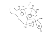
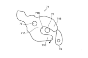
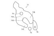
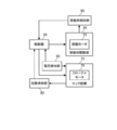
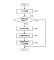
- FIG. 3 is a partially enlarged side view of a rear portion of an automobile equipped with the moving body moving device according to the present embodiment. It is a figure which shows the full latch state in a lock mechanism. It is a figure which shows a mode that a lock mechanism changes from a full latch state to a half latch state. It is a figure which shows the half latch state in a lock mechanism. It is a figure which shows the unlatched state in a lock mechanism. It is a block diagram with which a control system of a mobile unit moving device is explained. 7 is a flowchart for explaining a drive control of a latch in the moving device moving apparatus.
- the moving body moving apparatus 1 As an example of the moving body moving apparatus 1, an automobile whose back door is moved and controlled is illustrated.
- the moving body moving apparatus 1 includes a shutter and a sliding door installed in a structure such as a store or a garage.
- the present invention is also applicable to a device that controls the movement of a folding door or a folding eave arranged above an opening in the front of a structure.
- FIG. 1 is a schematic side view of an automobile equipped with a moving body moving device 1 of the present embodiment.
- the moving body moving apparatus 1 includes an opening member 10 as an example of a base body, a moving body 20, a moving body driving unit 30, a control unit 50, and a moving body detecting unit 60 (see FIG. 4). ), a lock mechanism 70 (see FIG. 2), a position detector 80 (see FIG. 4), and a voltage detector 90 (see FIG. 4).
- the moving body moving device 1 is a device that moves the moving body 20 with respect to the opening 11 of the opening member 10.
- the opening member 10 is provided at a rear portion with respect to the traveling direction of the vehicle body in the automobile using the moving body moving device 1 of the present embodiment.
- the opening member 10 is a vehicle body used in this automobile, and the opening portion 11 is formed by the edge portion of the opening member 10.
- the shape of the opening 11 may be any shape such as a rectangular shape or a circular shape.
- the moving body 20 is a back door of an automobile and transits to an open state (see FIG. 1) or a closed state (see FIG. 2).
- the open state of the moving body 20 is a state in which the opening 11 is opened, and in the rear part of the vehicle, an object such as luggage can be put in and out of the rear luggage compartment from the outside through the opening 11. ..
- the closed state of the moving body 20 is a state in which the opening 11 is closed. In other words, the closed state can be a state in which the moving body 20 is located at a position that prevents an object such as luggage from moving through the opening 11 to the opposite side. Further, the open state can be a state in which the moving body 20 is located at a position that allows the target object to move to the opposite side through the opening 11.
- the upper side portion of the moving body 20 is rotatably attached to the upper edge side of the opening 11 of the opening member 10 via a shaft portion serving as a hinge.
- the moving body 20 swivels around the shaft so that the lower side moves up and down, and contacts or separates from the opening 11 to transition the moving body 20 to the open state or the closed state.
- the position change of the moving body 20 is realized by the turning mechanism described above, but the mechanism for changing the position of the moving body 20 is not limited to turning, and the moving body 20 is opened or closed. Any mechanism may be used as long as it can transit to the state.
- the mobile body 20 may be of any type as long as it can transit to the open state or the closed state, and may be, for example, a slide door.
- the moving body drive unit 30 moves the moving body 20 in the opening direction and the closing direction with respect to the opening 11 of the opening member 10.
- two moving body drive units 30 are provided, one on each of the left and right ends of the moving body 20 and on both the left and right edges of the opening 11.
- the two moving body drive units 30 move as long as the moving body 20 can be moved in a direction that opens the moving body 20 (opening direction) and a direction that closes the moving body 20 (closing direction).
- the body drive units 30 may drive the moving body 20 in the same direction and with the same drive amount. Further, if each of the two moving body driving units 30 can move the moving body 20 in the opening direction and the closing direction, the moving body 20 can be driven with different driving amounts even if driving in different directions. You can In the present embodiment, each moving body drive unit 30 is provided to perform the same drive in synchronization.
- the moving body drive unit 30 is provided so as to be passed between the opening member 10 and the moving body 20 so that the moving body 20 can move relative to the opening member 10.
- each of the moving body driving units 30 swivels with respect to the opening member 10 so as to be driven while swiveling following the swiveling of the moving body 20. It is possible to install.
- each moving body driving unit 30 has an expanding and contracting rod-shaped appearance, is arranged on one end side of the moving body driving unit 30, and is connected to the opening member 10 side, and a driving main body unit, It has an advancing/retreating portion which is disposed on the other end side of the moving body drive unit 30 and is connected to the moving body 20 side.
- the advancing/retreating part is attached so as to be retractable from the other end side of the drive body part.
- the moving body drive unit 30 advances and retreats the moving body drive unit in the longitudinal direction of the moving body drive unit 30 to fully close the moving body 20, that is, a position where the opening 11 is completely closed. It can be moved to a fully open position, that is, a position where the opening 11 is opened to the maximum extent.
- Each moving body drive unit 30 moves the moving body 20 in the opening direction or the closing direction by converting the rotational movement of a motor or the like into a linear expansion/contraction movement.
- the moving body drive unit 30 was provided at each of the left and right ends of the rear part of the automobile, one in total, but the number of mobile units to be used is not particularly limited. Further, the structure, shape, and arrangement position of the moving body drive unit 30 are not particularly limited as long as the moving body 20 can be moved.
- the moving body drive unit 30 can employ a known driving unit that can drive the moving body 20.
- the moving body drive unit 30 includes a main body tubular portion 31, a slide tubular portion 32, a moving motor 33 (see FIG. 4), a spindle (not shown), a spindle nut (not shown), and a biasing member (not shown). Omitted) etc.
- the main body cylinder portion 31, the moving motor 33, the spindle, the urging member and the like correspond to the drive main body portion
- the slide cylinder portion 32 and the spindle nut correspond to the advancing and retracting portion.
- the body tube portion 31 has one end side rotatably fixed to the opening member 10 and the other end side open. Inside the main body tubular portion 31, a slide tubular portion 32 is arranged so as to be slidable in the longitudinal direction so as to project and retract from the other end side of the main body tubular portion 31.
- the moving motor 33 is driven to move the advancing/retreating part in the longitudinal direction with respect to the drive main body part to extend and contract the moving body drive part 30.
- the moving motor 33 is a DC motor or an AC motor.
- the movement motor 33 is connected to the control unit 50, and the control unit 50 controls both forward rotation and reverse rotation driving.
- the slide tubular portion 32 is biased by the biasing member from one end side of the main body tubular portion 31 toward the other end side.
- a spindle nut is provided inside the slide cylinder portion 32 in which a spindle that rotates around an axis by the rotation of the moving motor 33 is screwed.
- the moving body drive unit 30 is configured so that the main body cylinder portion 31 and the slide cylinder portion 32 do not rotate with each other due to the rotation of the spindle.
- the moving motor 33 rotates in one of the forward and reverse directions
- the spindle rotates in one direction around the forward and reverse axes
- the spindle nut screwed to the spindle moves along the longitudinal direction of the spindle.
- the slide cylinder portion 32 having the spindle nut moves forward and backward, that is, slides in the longitudinal direction.
- the moving body drive unit 30 moves so as to expand and contract, and the moving body 20 operates in accordance with the length that the slide cylinder portion 32 advances from the main body cylinder portion 31.
- FIG. 2 is a partially enlarged side view of a rear portion of an automobile equipped with the moving body moving device according to the present embodiment.
- FIG. 3A is a diagram showing a fully latched state in the lock mechanism.
- FIG. 3B is a diagram showing how the lock mechanism transitions from the full latch state to the half latch state.
- FIG. 3C is a diagram showing a half-latch state in the lock mechanism.
- FIG. 3D is a diagram showing an unlatched state in the lock mechanism.
- the lock mechanism 70 is a mechanism provided for locking the moving body 20 in the closed state with respect to the opening 11, and includes a latch 71, a striker 72, and a rotating shaft 73. , A pole 74, and a closure motor 75 (see FIG. 4).
- the latch 71 is a member that can be engaged with the striker 72, and is provided at the inner lower end of the moving body 20.
- the latch 71 has a base 71A, a first arm 71B extending from the upper end of the base 71A, and a second arm 71C extending from the lower end of the base 71A.
- the first arm 71B and the second arm 71C extend from the base 71A in the same direction (direction from left to right in FIG. 3A).
- the latch 71 is a feature that corresponds to the "engagement portion" according to this invention.
- the striker 72 is a member that can be engaged with the latch 71, and has a rod-shaped portion that can be inserted into a recess 71D formed by the base 71A of the latch 71, the first arm 71B, and the second arm 71C. There is.
- the rod-shaped portion of the striker 72 is, for example, a portion parallel to the left-right direction in FIG.
- the striker 72 is a feature that corresponds to the "engaged portion" according to this invention.
- the striker 72 is configured such that, at the lower edge portion of the opening 11 of the opening member 10 of the moving body 20, when the moving body 20 is in the closed state, the rod-shaped portion engages with the latch 71 in the full latch state. It is provided in the position.
- the striker 72 is provided on the moving body 20 side.
- the latch 71 is configured to be rotatable around a rotation shaft 73.
- the latch 71 is rotated, for example, by the driving force of the closure motor 75 to be in a full latch state (state of FIG. 3A), a half latch state (state of FIG. 3C), and an unlatch state (state of FIG. 3D). Transition.
- the full-latch state is a state in which the striker 72 is locked by the latch 71. More specifically, the full-latch state is a fully-engaged state in which the striker 72 engages so as not to be disengaged from the recess 71D of the latch 71.
- the half-latch state is a state in which the striker 72 can be easily disengaged from the recess 71D of the latch 71 when an external force is applied, and the striker 72 engages with the latch 71 (position in the full-latch state). ) Is ready to move.
- the unlatched state is a state in which the engagement between the latch 71 and the striker 72 is completely released.
- the latch 71 in the unlatched position is in a state in which the striker 72 can be received in the recess 71D.
- the latch 71 may be biased by a biasing member (not shown) so as to rotate clockwise in FIGS. 3A to 3D.
- a biasing member not shown
- the rotation of the pole 74 described later can be controlled, and the latch 71 can be rotated from the full latch state to the unlatch state by the urging force of the urging member.
- the pole 74 is a member capable of restricting the rotation of the latch 71, and is provided at a position where it can come into contact with either the first arm 71B or the second arm 71C of the latch 71.
- the pawl 74 is rotatably provided, and is driven by the closure motor 75 from the upstream side in the clockwise direction to the first position (see FIG. 3A), the second position (see FIG. 3C), and the third position (see FIG. 3C). 3D) (see FIG. 3D).
- the closure motor 75 is a DC motor or an AC motor, and changes the state of the latch 71 in the lock mechanism 70 by rotating the latch 71 and the pole 74.
- the closure motor 75 is connected to the control unit 50, and the control unit 50 controls the rotation drive of both forward rotation and reverse rotation.
- the closure motor 75 is a feature that corresponds to the "drive unit" according to this invention.
- the striker 72 is inserted into the recess 71D of the latch 71 by the movement of the moving body 20 by the moving body driving unit 30 in a state where the latch 71 is positioned at the unlatched position.
- the driving force of the closure motor 75 causes the latch 71 to rotate counterclockwise.
- the lock mechanism 70 enters the half-latch state.
- the latch 71 may be forcibly moved from the position in the unlatch state to the position in the half-latch state by the movement of the moving body 20 by the moving body drive unit 30.
- lock mechanism 70 may have any structure as long as it can be driven by the closure motor 75.
- FIG. 4 is a block diagram showing a control system of the moving body moving apparatus 1.
- the control system includes a control unit 50, a moving body detection unit 60, a position detection unit 80, and a voltage detection unit 90.
- the control system of the moving body moving apparatus 1 controls the moving body 20 driven by the moving body drive unit 30 including the moving motor 33.
- the moving body detection unit 60 detects the movement of the position of the moving body 20 by detecting the operation of the moving body drive unit 30, and outputs the movement information of the moving body 20 which is the detection result to the control unit 50. ..
- the moving body detection unit 60 includes a Hall element, and magnetically detects the rotation state of the moving motor 33 to detect the operation of the moving body drive unit 30 and thus the movement of the position of the moving body 20.
- magnets are arranged at different intervals in the circumferential direction on a disk provided on the rotary shaft of the moving motor 33, and the Hall element of the moving body detection unit 60 is arranged at a position facing this.
- the Hall element captures the magnet that moves with the rotation of the rotary shaft of the moving motor 33 and generates a pulse.
- the control unit 50 calculates the position of the moving body 20 based on the count value obtained by counting the pulses, and calculates the drive speed of the moving body 20 based on the change in the count value.
- the moving body detection unit 60 counts the captured pulses, and the control unit 50 uses the count value as movement information of the moving body 20 to calculate the pulse count value for calculating the position and drive speed of the moving body 20 in the control unit 50. Make it available. Note that the moving body detection unit 60 calculates not only the number of pulses but also the position and drive speed of the moving body 20 based on the count value, and then outputs the calculation result to the control unit 50. You can
- the moving body detection unit 60 may have any configuration as long as it can detect the information on the movement of the position of the moving body 20, for example, directly without detecting the operation of the moving body drive unit 30. Alternatively, the movement of the position of the moving body 20 may be detected.
- the detection method is not limited to magnetic detection using a Hall element, and any method may be used as long as it can generate a count value according to the position of the moving body 20.
- the moving body detection unit 60 has been described here as being provided separately from the control unit 50 described later, the moving body detection unit 60 may be incorporated in the control unit 50.
- the control unit 50 stores a preset count value according to the output result of the moving body detection unit 60, for example. It may be obtained from.
- the position detector 80 detects the position of the latch 71. Specifically, the position detection unit 80 is provided in, for example, the lock mechanism 70, detects the unlatched state of the lock mechanism 70, and outputs the detection result to the control unit 50. The position detection unit 80 detects whether or not the latch 71 is engaged with the striker 72, for example, based on the rotating state of the latch 71.
- the position detection unit 80 shifts to a position where the latch 71 is not engaged with the striker 72, that is, in the state of FIG. 3D, transitions to an OFF state, and a position where the latch 71 is engaged with the striker 72, that is, In the states of FIGS. 3A to 3C, a detection switch that transitions to the ON state is included.
- the lock mechanism 70 is provided with a link mechanism (not shown), and the detection switch is switched between the ON state and the OFF state in accordance with the rotating state of the latch 71 through the link mechanism.
- the control unit 50 determines whether or not the latch 71 is engaged with the striker 72 based on the signal in the ON state and the signal in the OFF state output from the position detection unit 80.
- the position detection unit 80 may include a switch capable of detecting the unlatch state and the full latch state.
- the position detection unit 80 may be any type as long as it can detect the latched state of the lock mechanism 70.
- the position detection unit 80 may not be provided in the mobile unit moving device 1. In this case, the mobile unit moving apparatus 1 may be able to obtain the latched state detection signal from the outside.
- the voltage detector 90 measures the voltage value applied to the closure motor 75.
- the voltage detection unit 90 is, for example, a voltage detection circuit provided in the control unit 50, and measures the voltage value applied to the closure motor 75 from the terminal of the closure motor 75 or the like.
- the voltage detector 90 may be of any type as long as it can measure the voltage value applied to the closure motor 75.
- the control unit 50 includes a CPU (Central Processing Unit), a ROM (Read Only Memory), A RAM (Random Access Memory) and the like are provided.
- the CPU reads out a program according to the processing content from the ROM, expands it in the RAM, and centrally controls the operation of each block of the mobile unit 1 in cooperation with the expanded program.
- various data stored in the storage unit (not shown) is referred to.
- the storage unit (not shown) is composed of, for example, a nonvolatile semiconductor memory (so-called flash memory) or a hard disk drive.
- the control unit 50 may be incorporated in, for example, an ECU (Electronic Control Unit) that controls each unit of the vehicle, or may be mounted in the moving body drive unit 30.
- the control unit 50 controls the moving body drive unit 30 so that the moving body 20 moves between the open state and the closed state. Further, the control unit 50 controls the engagement operation and the release operation of the latch 71 and the striker 72 by the closure motor 75.
- the control unit 50 does not have to be integrated, and a plurality of control elements forming the control unit 50 may control the moving body drive unit 30 and the lock mechanism, respectively.
- the control unit 50 controls the release operation of the latch 71 and the striker 72 when the moving body 20 transits from the closed state to the open state. Specifically, the control unit 50 controls the lock mechanism 70 so that the engagement between the latch 71 and the striker 72 is released. The control unit 50 controls the closure motor 75 so as to move the latch 71 from the position in the full latch state shown in FIG. 3A to the position in the unlatch state shown in FIG. 3D. The control unit 50 controls the movement motor 33 based on the detection result of the position detection unit 80 so as to move the moving body 20 toward the open state.
- the signal of the position detection unit 80 is switched from the ON state to the OFF state.
- the moving body 20 is controlled to move toward the open state when the signal of the position detection unit 80 is switched from the ON state to the OFF state.
- the control unit 50 controls the engagement operation between the latch 71 and the striker 72 when the moving body 20 transits from the open state to the closed state. Specifically, the control unit 50 controls the lock mechanism 70 so that the latch 71 and the striker 72 are engaged with each other. The control unit 50 controls the moving motor 33 so as to move the moving body 20 toward the closed state.
- the control unit 50 moves the latch 71 to the unlatched position. 75 may be controlled. After that, the control unit 50 controls the moving motor 33 to move the moving body 20 toward the closed state.
- the standby position is, for example, a position on the downstream side in the clockwise direction with respect to the position shown in FIG. 3D, and the recess 71D of the latch 71 cannot receive the striker 72 and cannot engage with it.
- the position of the latch 71 in the unlatch state can be, for example, an intermediate position between the position in the full latch state and the standby position.
- the control unit 50 drives the closure motor 75 to cause the latch 71 to transition from the unlatch state to the full latch state. As a result, the moving body 20 is locked in the closed state.
- the control unit 50 detects the closure motor 75 based on the detection result of the position detection unit 80. May be driven. Specifically, the striker 72 enters the recess 71D of the latch 71 and presses the latch 71, whereby the latch 71 transitions from the unlatch state to the half-latch state.
- the signal of the position detection unit 80 switches from the OFF state to the ON state.
- the closure motor 75 is controlled so that the latch 71 changes from the half latch state to the full latch state.
- the control unit 50 may control the closure motor 75 based on the detection result of the moving body detection unit 60 instead of the detection result of the position detection unit 80.
- control unit 50 controls the closure motor 75 based on the preset drive time when the latch 71 moves from the movement start position to the predetermined position. Specifically, the control unit 50 controls the closure motor 75 for the drive time required for the latch 71 to move from the movement start position to the predetermined position.
- the movement start position of the latch 71 is the position in the full latch state when the moving body 20 is in the closed state.
- the movement start position of the latch 71 may be the position in the unlatched state when the moving body 20 is in the open state, or the standby position described above.
- the predetermined position can be a position in the unlatch state where the latch 71 can open or receive the striker 72 when the movement start position of the latch 71 is the full latch state position or the standby position. .. Further, the predetermined position may be, for example, a position in a full latch state when the movement start position of the latch 71 is a position in an unlatch state. The predetermined position may be a position that is arbitrarily determined.
- the control unit 50 controls the closure motor 75 so as to adjust the position of the latch 71 when it is determined that the position detection unit 80 is abnormal during the movement of the latch 71 from the movement start position to the predetermined position.
- the position detection unit 80 is abnormal when, for example, it is possible to determine that the position detection unit 80 has failed because the signal of the position detection unit 80 does not change.
- the latch 71 moves between the position in the fully latched state and the position in the unlatched state
- the signal of the position detection unit 80 switches between the ON state and the OFF state.
- the latch 71 moves between the position in the fully latched state and the position in the unlatched state
- the position detection unit 80 is out of order
- the signal of the position detection unit 80 does not change. Therefore, it is also possible to determine that the position detection unit 80 has failed because the signal of the position detection unit 80 does not change.
- the position detection unit 80 when the position detection unit 80 is abnormal, the voltage of the closure motor 75 changes due to the ambient temperature of the moving body moving apparatus 1 or the operating environment of the moving body moving apparatus 1, and the latch 71 is kept in a predetermined state. There is also a case where it can be determined that it has not moved to the position.
- the voltage applied to the closure motor 75 decreases. Further, in the moving body moving apparatus 1, there is a case where the electric power of the battery is consumed in a portion other than the moving motor 33 and the closure motor 75 such as the operation of the air conditioner in the vehicle body. In this case, the voltage applied to the closure motor 75 becomes relatively low.
- the movement amount of the latch 71 changes based on the drive amount of the closure motor 75 in the preset drive time.
- a situation occurs in which the latch 71 does not move to the position assumed by the latch 71.
- the latch 71 moves from the position in the full-latch state to the position in the unlatch state, if the amount of movement to the position in the unlatch state is insufficient, the signal from the position detector 80 naturally does not change. In such a case, it can be determined that the latch 71 has not moved to the predetermined position.
- the latch 71 moves from the standby position to the position in the unlatch state, if the latch 71 moves past the position in the unlatch state and moves to the position in the half-latch state, the signal of the position detector 80 is turned on. .. That is, also in this case, it can be determined that the latch 71 has not moved to the predetermined position.
- control unit 50 determines from the detection result of the position detection unit 80 that the position of the latch 71 is not the position in the unlatched state, and thus the determination criterion for moving the moving body 20 cannot be satisfied.
- the control unit 50 determines that the position detection unit 80 is abnormal, the position of the latch 71 is adjusted.
- the control unit 50 performs necessary driving based on the first initial voltage of the closure motor 75 and the reference electricity amount at the movement start position. Calculate time.
- the first initial voltage is an initial voltage applied to the closure motor 75 at the movement start position when the latch 71 moves from the movement start position to the current position, and is a value based on the detection result of the voltage detection unit 90. ..
- the reference amount of electricity is an amount of electricity obtained by multiplying the time required for the past movement from the movement start position of the latch 71 to a predetermined position by the second initial voltage in the closure motor 75 at the movement start position during the movement. Is.
- the past movement is the latest movement, for example, of the past movement history of the latch 71 when the position detection unit 80 is not abnormal.
- the reference amount of electricity in consideration of aging deterioration of the closure motor 75 and the like.
- a preset initial value of the reference electricity amount may be used.
- the reference amount of electricity is not limited to the above-mentioned past movement and may be the above-mentioned initial value.
- the control unit 50 may calculate the reference amount of electricity at the timing when it is determined that the position detection unit 80 is abnormal, or may be calculated at the timing of the past movement.
- the control unit 50 stores the calculated reference electricity amount in, for example, a storage unit (not shown).
- the control unit 50 calculates the difference value between the current moving electricity amount obtained by multiplying the first initial voltage and the drive time of the closure motor 75 during the movement of the latch 71 from the movement start position to the current position, and the reference electricity amount. To do. Then, based on the difference value and the first initial voltage, the control unit 50 controls the closure motor 75, which is required to move the latch 71 from the current position to the predetermined position where the latch 71 should originally be located. Calculate the required drive time.
- the control unit 50 drives the closure motor 75 for the required driving time.
- the latch 71 moves from the current position to the predetermined position.
- the control unit 50 drives the closure motor 75 so as to move the latch 71 by the shortage.
- the control unit 50 drives the closure motor 75 so as to return the latch 71 by the amount of passing the predetermined position.
- the latch 71 can be moved to the predetermined position. Therefore, even when the voltage applied to the closure motor 75 changes, the latch 71 of the lock mechanism 70 driven by the closure motor 75 can be controlled to be located at a predetermined position.
- the control unit 50 may determine that the position detection unit 80 is out of order. By doing so, the position detection unit 80 can accurately determine whether or not there is a failure. Further, in this case, the control unit 50 may output a notification command for notifying the surroundings that the position detection unit 80 is out of order. By doing so, it is possible to promptly inform the user of the failure of the position detection unit 80.
- FIG. 5 is a flowchart for explaining the drive control of the latch 71 in the mobile unit moving device 1.
- the control in FIG. 5 is executed, for example, when an operation instruction for moving the moving body 20 is received.
- control unit 50 controls the closure motor 75 to drive the latch 71 (step S101).
- control unit 50 determines whether the position detection unit 80 has an abnormality (step S102).
- step S102 If the result of determination is that there is no abnormality in the position detection unit 80 (step S102, NO), this control ends. On the other hand, when the position detection unit 80 has an abnormality (YES in step S102), the control unit 50 calculates the reference electricity amount (step S103).
- control unit 50 calculates the required drive time of the closure motor 75 based on the calculated reference electricity amount (step S104). Then, the control unit 50 controls the closure motor 75 so as to drive the latch 71 for the calculated required driving time (step S105). Then, this control ends. After step S105, the movement control of the moving body 20 and the control of moving the latch 71 to the fully latched position or the like are appropriately performed.
- the latch 71 can be moved to the predetermined position. You can That is, even when the voltage applied to the closure motor 75 changes, the latch 71 of the lock mechanism 70 driven by the closure motor 75 can be controlled to be located at a predetermined position. As a result, the engaging operation and the releasing operation of the latch 71 and the striker 72 can be performed with high accuracy.
- the reference amount of electricity is calculated based on the time required for the latest movement when the position detection unit 80 is not abnormal in the past movement history of the latch 71, the aged deterioration of the closure motor 75 is considered. It is possible to calculate the reference amount of electricity. As a result, an accurate required drive time can be calculated.
- the position detection unit 80 determines the abnormality of the position detection unit 80 based on the signal fluctuation based on only the unlatched position, but the present invention is not limited to this.
- the position detection unit 80 may determine the abnormality of the position detection unit 80 based on a signal change based on at least one of the unlatched position, the half latched position, and the fully latched position.
- the control in the case where the movement start position of the latch 71 is the position in the full latch state or the standby position has been illustrated, but the present invention is not limited to this, and the movement start position of the latch 71 is It may be in the unlatched position.
- the position detection unit 80 only needs to be able to detect whether or not the lock mechanism 70 is in the fully latched state.
- the latch 71 moves from the unlatched position to the fully latched position, if the voltage applied to the closure motor 75 changes, and the latch 71 does not move sufficiently to the fully latched position, the opening member of the moving body 20 is opened. The lock on 10 becomes loose.
- the signal of the position detection unit 80 does not change because the latch 71 has not moved to the position of the full latch state. Therefore, the control unit 50 determines that the position detection unit 80 is abnormal, and calculates the required drive time from the current position to the predetermined position. Then, the controller 50 drives the closure motor 75 for the required drive time to move the latch 71 to a predetermined position (position in the full latch state). As a result, the accuracy of movement of the latch 71 can be improved.
- control unit 50 controls the moving body drive unit 30 and the lock mechanism 70, but the present invention is not limited to this, and the plurality of control units may control the moving body drive unit and the lock mechanism. The mechanism may be controlled separately.
- the moving body moving device according to the present invention is useful as a moving body moving device capable of controlling the engaging portion of the lock mechanism driven by the driving portion to be located at a predetermined position even when the voltage changes. is there.
Landscapes
- Engineering & Computer Science (AREA)
- Mechanical Engineering (AREA)
- Power-Operated Mechanisms For Wings (AREA)
- Lock And Its Accessories (AREA)
Abstract
移動体移動装置は、基体に対して開位置と閉位置との間で移動する移動体と、被係合部と、被係合部に係合する係合部と、係合作動及び解除作動を行う駆動部と、係合部の位置を検知する位置検知部とを有するロック機構と、駆動部を制御する制御部と、駆動部の電圧を測定する電圧検知部と、を備えた移動体移動装置であって、制御部は、係合部の移動開始位置から所定位置までの移動に要した時間に対して、該移動の初期の電圧を乗じた基準電気量を算出し、移動開始位置から所定位置までの移動において位置検知部が異常であると判断したときに、該移動の際の移動開始位置からの移動の移動初期電圧と基準電気量から必要駆動時間を算出して、駆動部を必要駆動時間だけ駆動させることで、電圧が変化した場合でも、駆動部によって駆動するロック機構の係合部を所定の位置に位置するように制御することができる。
Description
本発明は、移動体移動装置に関する。
基体の開口部を開状態または閉状態とする移動体については、閉位置において移動体の被係合部がラッチ等のロック機構の係合部と係合して移動体がロックされる。このとき、係合部は、位置検知部からの情報に基づいて駆動部が駆動し、被係合部と係合可能な所定の位置へと移動する。
しかし、位置検知部の故障により係合部が、被係合部と係合可能な所定の位置へと移動できない場合には、移動体の被係合部とロック機構の係合部とが係合することができず、移動体をロック状態とすることができず、また、過剰な移動によってモータ等に障害が生じることも考えられる。
このような問題に対しては、例えば特許文献1には、ロック機構であるクロージャのモータによる復帰回動時に、復帰確認スイッチが故障しても、一旦全閉位置まで閉じてからモータの一定時間の逆回転によってラッチを所定の位置に復帰させる自動ドア閉止装置が提案されている。
しかし、このような一定時間のモータの回転により、所定の位置にラッチを移動させる装置を用いた場合には、温度や作動環境によって電圧が変化してしまうと、移動後のラッチの位置が所定の位置とは異なる位置となる場合がある。
本発明の目的は、電圧が変化した場合でも、駆動部によって駆動するロック機構の係合部を所定の位置に位置するように制御することが可能な移動体移動装置を提供することである。
本発明の移動体移動装置は、
基体に対して開位置と閉位置との間で移動する移動体と、
前記基体及び前記移動体の一方に設けられた被係合部と、
前記基体及び前記移動体の他方に設けられて前記被係合部に係合する係合部と、前記係合部と、前記被係合部との係合作動及び解除作動を行う駆動部と、前記係合部の位置を検知する位置検知部とを有するロック機構と、
前記駆動部による係合作動と解除作動とを制御する制御部と、
前記駆動部の電圧を測定する電圧検知部と、
を備えた移動体移動装置であって、
前記制御部は、
前記係合部の移動開始位置から所定位置までの移動に要した時間に対して、該移動の初期の電圧を乗じた基準電気量を算出し、
前記移動開始位置から前記所定位置までの移動において前記位置検知部が異常であると判断したときに、該移動の際の前記移動開始位置からの移動の移動初期電圧と前記基準電気量から必要駆動時間を算出して、前記駆動部を前記必要駆動時間だけ駆動させる。
基体に対して開位置と閉位置との間で移動する移動体と、
前記基体及び前記移動体の一方に設けられた被係合部と、
前記基体及び前記移動体の他方に設けられて前記被係合部に係合する係合部と、前記係合部と、前記被係合部との係合作動及び解除作動を行う駆動部と、前記係合部の位置を検知する位置検知部とを有するロック機構と、
前記駆動部による係合作動と解除作動とを制御する制御部と、
前記駆動部の電圧を測定する電圧検知部と、
を備えた移動体移動装置であって、
前記制御部は、
前記係合部の移動開始位置から所定位置までの移動に要した時間に対して、該移動の初期の電圧を乗じた基準電気量を算出し、
前記移動開始位置から前記所定位置までの移動において前記位置検知部が異常であると判断したときに、該移動の際の前記移動開始位置からの移動の移動初期電圧と前記基準電気量から必要駆動時間を算出して、前記駆動部を前記必要駆動時間だけ駆動させる。
本発明によれば、電圧が変化した場合でも、駆動部によって駆動するロック機構の係合部を所定の位置に位置するように制御することができる。
以下、本実施の形態を図面に基づいて詳細に説明する。なお、本実施の形態では、移動体移動装置1の一例として、バックドアを移動制御する自動車を例示するが、移動体移動装置1は、店舗やガレージ等の構造物に設置されるシャッター、引き戸、開き扉、または、構造物正面の開口の上方に配置される折りたたみ式の庇の移動を制御する装置にも適用可能である。
[移動体移動装置の全体構成]
図1は、本実施の形態の移動体移動装置1を備えた自動車の概略側面図である。
図1は、本実施の形態の移動体移動装置1を備えた自動車の概略側面図である。
図1に示すように、移動体移動装置1は、基体の一例としての開口部材10と、移動体20と、移動体駆動部30と、制御部50と、移動体検知部60(図4参照)と、ロック機構70(図2参照)と、位置検知部80(図4参照)と、電圧検知部90(図4参照)とを備える。
移動体移動装置1は、開口部材10の開口部11に対して移動体20を移動する装置である。
[開口部材]
開口部材10は、本実施の形態の移動体移動装置1を用いた自動車において、車体の進行方向に対して後部に設けられている。開口部材10は、この自動車に用いられる車体であり、開口部材10の縁部によって開口部11が形成されている。開口部11の形状は、矩形状、円形状等、どのような形状であっても良い。
開口部材10は、本実施の形態の移動体移動装置1を用いた自動車において、車体の進行方向に対して後部に設けられている。開口部材10は、この自動車に用いられる車体であり、開口部材10の縁部によって開口部11が形成されている。開口部11の形状は、矩形状、円形状等、どのような形状であっても良い。
[移動体]
移動体20は、自動車のバックドアであり、開状態(図1参照)または、閉状態(図2参照)に遷移する。移動体20における開状態は、開口部11を開放した状態であり、車両の後部においては、荷物等の対象物を、開口部11を介して外部から後部荷室に入出可能とする状態である。移動体20における閉状態は、開口部11を閉塞した状態である。換言すると、閉状態は、荷物等の対象物が開口部11を通って反対側へ移動することを阻害する位置に移動体20があるときの状態とすることができる。また、開状態は、当該対象物が開口部11を通って反対側へ移動することを許容する位置に移動体20があるときの状態とすることができる。
移動体20は、自動車のバックドアであり、開状態(図1参照)または、閉状態(図2参照)に遷移する。移動体20における開状態は、開口部11を開放した状態であり、車両の後部においては、荷物等の対象物を、開口部11を介して外部から後部荷室に入出可能とする状態である。移動体20における閉状態は、開口部11を閉塞した状態である。換言すると、閉状態は、荷物等の対象物が開口部11を通って反対側へ移動することを阻害する位置に移動体20があるときの状態とすることができる。また、開状態は、当該対象物が開口部11を通って反対側へ移動することを許容する位置に移動体20があるときの状態とすることができる。
本実施の形態において、移動体20の上辺部は、開口部材10における開口部11の上縁部側にヒンジとしての軸部を介して回動可能に取り付けられている。移動体20は、軸部を中心に下辺部側が上下動するように旋回し、開口部11から接触または離間することにより、移動体20を開状態または閉状態に遷移させる。本実施の形態では、移動体20の位置変更が上記の旋回機構によって実現されているが、移動体20の位置変更のための機構は、旋回に限定されず、移動体20を開状態または閉状態に遷移させることができればいかなる機構であっても良い。
なお、移動体20は、開状態または閉状態に遷移可能なものである限り、どのようなものでも良く、例えば、スライドドアであっても良い。
[移動体駆動部]
移動体駆動部30は、開口部材10の開口部11に対して移動体20を開方向と閉方向とに移動させる。移動体駆動部30は、複数あっても良い。本実施の形態では、移動体駆動部30は、移動体20の左右両端および開口部11の左右の両縁に1つずつの計2つ設けられている。それぞれの移動体駆動部30が駆動することにより移動体20を移動させることで、移動体20は、開口部材10に対して相対移動して、開状態または閉状態に遷移する。
移動体駆動部30は、開口部材10の開口部11に対して移動体20を開方向と閉方向とに移動させる。移動体駆動部30は、複数あっても良い。本実施の形態では、移動体駆動部30は、移動体20の左右両端および開口部11の左右の両縁に1つずつの計2つ設けられている。それぞれの移動体駆動部30が駆動することにより移動体20を移動させることで、移動体20は、開口部材10に対して相対移動して、開状態または閉状態に遷移する。
2つの移動体駆動部30は、移動体20を開状態とする方向(開方向)と、移動体20を閉状態とする方向(閉方向)とに移動体20を移動可能であれば、移動体駆動部30のそれぞれが同方向であって同一駆動量で移動体20を駆動しても良い。また、2つの移動体駆動部30のそれぞれが、開方向と閉方向とに移動体20を移動可能であれば、異なる方向の駆動であっても、異なる駆動量で移動体20を駆動するようにしても良い。本実施の形態においては、各移動体駆動部30が同一の駆動を同期して行うように設けられている。
移動体駆動部30は、開口部材10と移動体20とに渡されて、移動体20が開口部材10に対して相対移動可能に設けられている。移動体20が開口部材10に対して旋回移動するために、移動体駆動部30のそれぞれは、移動体20の旋回に追随して旋回しながら駆動可能なように、開口部材10に対して旋回可能に取り付けられている。
具体的には、各移動体駆動部30は、伸縮する棒状の外観を有しており、移動体駆動部30の一端部側に配置され、開口部材10側に接続される駆動本体部と、移動体駆動部30の他端部側に配置され、移動体20側に接続される進退部とを有する。進退部は、駆動本体部の他端部側から出没可能に取り付けられている。
移動体駆動部30は、駆動本体部に対して進退部を、移動体駆動部30の長手方向に進退させて移動体20を全閉位置、つまり、開口部11を完全に閉塞する位置と、全開位置、つまり、開口部11を最大限に開放する位置とに移動できる。各移動体駆動部30は、モータ等の回転運動を直線方向の伸縮運動に変換することにより、移動体20を開方向または閉方向に移動させる。
移動体駆動部30は、自動車後部の左右の両端にそれぞれ1つずつの計2個設けられていたが、その使用個数は特に限定されない。また、移動体駆動部30は、移動体20の移動を可能とするものであれば、その構造、形状や配置位置に付いては特に限定されない。移動体駆動部30は、移動体20を駆動させることができる公知の駆動部を採用することができる。
本実施の形態では、移動体駆動部30は、本体筒部31、スライド筒部32、移動モータ33(図4参照)、スピンドル(図示省略)、スピンドルナット(図示省略)、付勢部材(図示省略)等を有する。移動体駆動部30では、本体筒部31、移動モータ33、スピンドル、付勢部材等が駆動本体部に対応し、スライド筒部32、スピンドルナットが進退部に対応する。
本体筒部31は、一端部側が開口部材10に旋回可能に固定され、他端部側が開口している。本体筒部31の内側には、スライド筒部32が、本体筒部31の他端部側から出没するように、長手方向にスライド移動可能に配置される。
移動モータ33は、駆動して、駆動本体部に対し、進退部を長手方向に移動させて移動体駆動部30を伸縮させる。移動モータ33は、直流モータまたは交流モータである。移動体移動装置1が自動車に適用される場合には、自動車の直流電源を用いることを考慮して、移動モータ33として直流モータを適用することが望ましい。なお、移動モータ33は、制御部50に接続され、制御部50により、正回転、逆回転の双方の回転駆動が制御される。
スライド筒部32は、本体筒部31の一端側から他端側に向けて付勢部材により付勢されている。スライド筒部32の内部には、移動モータ33の回転により軸回りに回転するスピンドルが螺合されたスピンドルナットが設けられている。
移動体駆動部30は、本体筒部31とスライド筒部32とが、スピンドルの回転によって互いに供回りしないように構成されている。移動モータ33が正逆の一方に回転すると、スピンドルが正逆軸回りの一方に回転し、スピンドルに螺合するスピンドルナットがスピンドルの長手方向に沿って移動する。これに伴い、スピンドルナットを有するスライド筒部32が進退移動、つまり、長手方向にスライド移動する。これにより、移動体駆動部30が、伸縮するように可動し、本体筒部31からスライド筒部32が進出する長さに対応して、移動体20が作動する。
[ロック機構]
図2は、本実施の形態の移動体移動装置を備えた自動車後部の部分拡大側面図である。図3Aは、ロック機構におけるフルラッチ状態を示す図である。図3Bは、ロック機構におけるフルラッチ状態からハーフラッチ状態に遷移する様子を示す図である。図3Cは、ロック機構におけるハーフラッチ状態を示す図である。図3Dは、ロック機構におけるアンラッチ状態を示す図である。
図2は、本実施の形態の移動体移動装置を備えた自動車後部の部分拡大側面図である。図3Aは、ロック機構におけるフルラッチ状態を示す図である。図3Bは、ロック機構におけるフルラッチ状態からハーフラッチ状態に遷移する様子を示す図である。図3Cは、ロック機構におけるハーフラッチ状態を示す図である。図3Dは、ロック機構におけるアンラッチ状態を示す図である。
図2および図3Aに示すように、ロック機構70は、開口部11に対して移動体20を閉状態でロックするために設けられる機構であり、ラッチ71と、ストライカ72と、回動軸73と、ポール74と、クロージャモータ75(図4参照)とを有する。
ラッチ71は、ストライカ72と係合が可能な部材であり、移動体20の内側下端部に設けられている。ラッチ71は、基部71Aと、基部71Aの上端部から延びる第1アーム71Bと、基部71Aの下端部から延びる第2アーム71Cとを有する。第1アーム71Bおよび第2アーム71Cは、基部71Aから同じ方向(図3Aにおける左から右に向かう方向)にそれぞれ延びている。ラッチ71は、本発明の「係合部」に対応する。
ストライカ72は、ラッチ71と係合が可能な部材であり、ラッチ71の基部71A、第1アーム71Bおよび第2アーム71Cで形成される凹部71Dに入り込むことが可能な棒状の部分を有している。ストライカ72の棒状の部分としては、例えば、図2における左右方向に平行な部分である。ストライカ72は、本発明の「被係合部」に対応する。
ストライカ72は、移動体20において、開口部材10における開口部11の下縁部分において、移動体20が閉状態となった際に、当該棒状の部分がラッチ71にフルラッチ状態で係合するような位置に設けられている。なお、ラッチ71が開口部材10側に設けられる場合、ストライカ72は移動体20側に設けられる。
ラッチ71は、回動軸73を中心に回動可能に構成されている。ラッチ71は、例えば、クロージャモータ75の駆動力により回動することで、フルラッチ状態(図3Aの状態)と、ハーフラッチ状態(図3Cの状態)と、アンラッチ状態(図3Dの状態)とに遷移する。
フルラッチ状態は、ストライカ72がラッチ71によりロックされた状態である。より詳細には、フルラッチ状態は、ストライカ72がラッチ71の凹部71Dから離脱できないように係合する完全係合状態である。
ハーフラッチ状態は、フルラッチ状態のときよりもラッチ71とストライカ72との係合力が弱い状態である。より詳細には、ハーフラッチ状態は、ストライカ72が、外力が負荷されることによりラッチ71の凹部71Dから容易に離脱できる状態であり、ストライカ72がラッチ71と係合する位置(フルラッチ状態の位置)へと移動可能な状態である。
アンラッチ状態は、ラッチ71とストライカ72との係合が完全に解除された状態である。言い換えると、アンラッチ状態の位置のラッチ71は、凹部71D内にストライカ72を受入可能な状態である。
また、ラッチ71は、図示しない付勢部材により、図3A~図3Dにおいて、時計回り方向に回動するように付勢されていても良い。これにより、後述するポール74の回動を制御して、付勢部材の付勢力によりラッチ71をフルラッチ状態からアンラッチ状態に回動させることができる。
ポール74は、ラッチ71の回動を規制することが可能な部材であり、ラッチ71の第1アーム71Bおよび第2アーム71Cの何れかと当接可能な位置に設けられている。ポール74は、回動可能に設けられており、クロージャモータ75の駆動の下、時計回り方向における上流側から第1位置(図3A参照)、第2位置(図3C参照)および第3位置(図3D参照)に位置するように制御される。
クロージャモータ75は、直流モータまたは交流モータであり、ラッチ71およびポール74を回動させることで、ロック機構70におけるラッチ71の状態を変更する。なお、クロージャモータ75は、制御部50に接続され、制御部50により、正回転、逆回転の双方の回転駆動が制御される。クロージャモータ75は、本発明の「駆動部」に対応する。
ここで、ロック機構70における動作の一例について説明する。まず、ロック機構70がフルラッチ状態からアンラッチ状態に遷移する際の動作について説明する。
図3Aに示すように、ポール74が第1位置のとき、フルラッチ状態のラッチ71における第2アーム71Cの先端とポール74とが当接する。これにより、ラッチ71の回動
が規制されてラッチ71のフルラッチ状態が維持される。
が規制されてラッチ71のフルラッチ状態が維持される。
図3Bに示すように、ポール74が第1位置から時計回り方向に回動すると、第2アーム71Cとの当接が解除される。ラッチ71は、クロージャモータ75の駆動力により時計回り方向に回動する。
図3Cに示すように、ポール74がさらに回動して第2位置に位置すると、ポール74とラッチ71の第1アーム71Bとが当接する。このとき、ラッチ71は、ハーフラッチ状態の位置であり、ラッチ71の回動がポール74により規制されることにより、ラッチ71の位置がハーフラッチ状態の位置に維持される。
図3Dに示すように、ポール74がさらに回動して第3位置に位置すると、ポール74とラッチ71の第1アーム71Bとの当接が解除される。これにより、ラッチ71は、クロージャモータ75の駆動力により時計回り方向に回動して、アンラッチ状態の位置に位置する。すなわち、ラッチ71とストライカ72との係合が完全に解除される。
また、ポール74を第2位置から回動させなくても、ハーフラッチ状態のときのラッチ71とストライカ72との係合力は、フルラッチ状態のときと比べて弱くなっている。そのため、移動モータ33の駆動力により、移動体20を開方向に移動させる力によって、ラッチ71とストライカ72との係合を解除させることも可能である。
次に、ロック機構70がアンラッチ状態からフルラッチ状態に遷移する際の動作について説明する。まず、図3Cおよび図3Dに示すように、ラッチ71をアンラッチ状態の位置に位置させた状態で、移動体駆動部30による移動体20の移動により、ラッチ71の凹部71Dにストライカ72が入る。そして、クロージャモータ75の駆動力により、ラッチ71が反時計回りに回動する。これにより、ロック機構70がハーフラッチ状態となる。また、移動体駆動部30による移動体20の移動により、ラッチ71をアンラッチ状態の位置からハーフラッチ状態の位置に強制的に移動させても良い。
そして、クロージャモータ75の駆動力により、図3Aおよび図3Bに示すように、ラッチ71が反時計回り方向に回動して、ラッチ71の凹部71D内にストライカ72を引き込むようにしてロック機構70がフルラッチ状態となる。
なお、ロック機構70は、クロージャモータ75により駆動可能な構成であれば、どのような構成であっても良い。
[制御系の構成]
図4は、移動体移動装置1の制御系を示すブロック図である。
移動体移動装置1において、制御系は、制御部50と、移動体検知部60と、位置検知部80と、電圧検知部90とを備える。移動体移動装置1の制御系は、移動モータ33を備える移動体駆動部30により駆動される移動体20を制御する。
図4は、移動体移動装置1の制御系を示すブロック図である。
移動体移動装置1において、制御系は、制御部50と、移動体検知部60と、位置検知部80と、電圧検知部90とを備える。移動体移動装置1の制御系は、移動モータ33を備える移動体駆動部30により駆動される移動体20を制御する。
[移動体検知部]
移動体検知部60は、例えば移動体駆動部30の動作を検知することで、移動体20の位置の移動を検知し、その検知結果である移動体20の移動情報を制御部50に出力する。
移動体検知部60は、例えば移動体駆動部30の動作を検知することで、移動体20の位置の移動を検知し、その検知結果である移動体20の移動情報を制御部50に出力する。
例えば、移動体検知部60は、ホール素子を含み、移動モータ33の回転状態を磁気的に検知することで、移動体駆動部30の動作ひいては移動体20の位置の移動を検知する。この場合、移動モータ33の回転軸に設けた円盤に、磁石を周方向に異なる間隔で配置し、これに対向する位置に、移動体検知部60のホール素子を配置する。ホール素子により、移動モータ33の回転軸の回転に伴って移動する磁石を捕捉してパルスを発生させる。制御部50は、このパルスをカウントしたカウント値により、移動体20の位置を算出し、カウント値の変化により、移動体20の駆動速度を算出する。
移動体検知部60は、捕捉したパルスをカウントし、制御部50は、カウント値を移動体20の移動情報として、制御部50における移動体20の位置および駆動速度の算出にパルスのカウント値を使用できるようにする。なお、移動体検知部60が、パルスのカウントだけでなく、そのカウント値に基づく移動体20の位置および駆動速度の算出をも行ったうえで、その算出結果を制御部50へと出力するようにしても良い。
また、移動体検知部60は、移動体20の位置の移動に関する情報を検知可能であれば、どのような構成であっても良く、例えば、移動体駆動部30の動作を検知することなく直接的に移動体20の位置の移動を検知しても良い。検知の方式は、ホール素子を用いて磁気的に行うものに限られず、移動体20の位置に応じたカウント値を生成可能であれば、どのような方式であっても良い。また、ここでは移動体検知部60を、後述する制御部50とは別々に設けられるものとして説明したが、移動体検知部60は、制御部50に組み込まれたものであっても良い。
なお、移動体検知部60がカウント値ではない出力値を制御部50に出力する場合、例えば移動体検知部60の出力結果に応じて、予め設定されたカウント値を制御部50が記憶部等から取得するようにしても良い。
[位置検知部]
位置検知部80は、ラッチ71の位置を検知する。具体的には、位置検知部80は、例えば、ロック機構70に設けられ、ロック機構70のアンラッチ状態を検知して、その検知結果を制御部50に出力する。位置検知部80は、例えば、ラッチ71の回動状態に基づいて、ラッチ71がストライカ72に係合したか否かを検知する。
位置検知部80は、ラッチ71の位置を検知する。具体的には、位置検知部80は、例えば、ロック機構70に設けられ、ロック機構70のアンラッチ状態を検知して、その検知結果を制御部50に出力する。位置検知部80は、例えば、ラッチ71の回動状態に基づいて、ラッチ71がストライカ72に係合したか否かを検知する。
位置検知部80は、ラッチ71がストライカ72と係合してない状態の位置、つまり、図3Dの状態のとき、OFF状態に遷移し、ラッチ71がストライカ72と係合した状態の位置、つまり、図3A~図3Cの状態のとき、ON状態に遷移するような検知スイッチを含む。具体的には、ロック機構70には、図示しないリンク機構が設けられ、当該リンク機構を介することにより、ラッチ71の回動状態に応じて、検知スイッチがON状態とOFF状態とに切り替わる。これにより、後述する制御部50が、位置検知部80が出力する、ON状態時の信号およびOFF状態時の信号に基づいて、ラッチ71がストライカ72に係合しているか否かについて判定する。
また、位置検知部80は、アンラッチ状態やフルラッチ状態を検知可能なスイッチを含んでいても良い。
また、位置検知部80は、ロック機構70のラッチ状態を検知可能であれば、どのようなものであっても良い。
また、位置検知部80は、移動体移動装置1に設けられていなくても良い。この場合、移動体移動装置1が、外部からラッチ状態の検知信号を取得できるようにすれば良い。
[電圧検知部]
電圧検知部90は、クロージャモータ75に印加される電圧値を測定する。具体的には、電圧検知部90は、例えば制御部50内に設けられる電圧検知回路であり、クロージャモータ75の端子等から、クロージャモータ75に印加される電圧値を測定する。なお、電圧検知部90は、クロージャモータ75に印加される電圧値を測定可能であれば、どのようなものであっても良い。
電圧検知部90は、クロージャモータ75に印加される電圧値を測定する。具体的には、電圧検知部90は、例えば制御部50内に設けられる電圧検知回路であり、クロージャモータ75の端子等から、クロージャモータ75に印加される電圧値を測定する。なお、電圧検知部90は、クロージャモータ75に印加される電圧値を測定可能であれば、どのようなものであっても良い。
[制御部]
制御部50は、CPU(Central Processing Unit)、ROM(Read Only Memory)、
RAM(Random Access Memory)等を備える。CPUは、ROMから処理内容に応じたプログラムを読み出してRAMに展開し、展開したプログラムと協働して移動体移動装置1の各ブロックの動作を集中制御する。このとき、記憶部(図示略)に格納されている各種データが参照される。記憶部(図示略)は、例えば不揮発性の半導体メモリ(いわゆるフラッシュメモリ)やハードディスクドライブで構成される。制御部50は、例えば、車両の各部を制御するECU(Electronic Control Unit)に組み込まれても良く、また、移
動体駆動部30に搭載されていても良い。
制御部50は、CPU(Central Processing Unit)、ROM(Read Only Memory)、
RAM(Random Access Memory)等を備える。CPUは、ROMから処理内容に応じたプログラムを読み出してRAMに展開し、展開したプログラムと協働して移動体移動装置1の各ブロックの動作を集中制御する。このとき、記憶部(図示略)に格納されている各種データが参照される。記憶部(図示略)は、例えば不揮発性の半導体メモリ(いわゆるフラッシュメモリ)やハードディスクドライブで構成される。制御部50は、例えば、車両の各部を制御するECU(Electronic Control Unit)に組み込まれても良く、また、移
動体駆動部30に搭載されていても良い。
制御部50は、移動体20が開状態と閉状態との間で移動するように、移動体駆動部30を制御する。また、制御部50は、クロージャモータ75によるラッチ71とストライカ72との係合作動と解除作動とを制御する。制御部50は、一体で有る必要はなく、制御部50を構成する複数の制御要素が、それぞれ移動体駆動部30とロック機構とを制御してもよい。
まず、ラッチ71とストライカ72との解除作動の制御と、移動体20の移動制御について説明する。
制御部50は、移動体20を閉状態から開状態に遷移させる場合、ラッチ71とストライカ72との解除作動を制御する。具体的には、制御部50は、ラッチ71とストライカ72との係合が解除するようにロック機構70の制御を行う。制御部50は、ラッチ71を、図3Aに示すフルラッチ状態の位置から図3Dに示すアンラッチ状態の位置に移動させるように、クロージャモータ75を制御する。制御部50は、位置検知部80の検知結果に基づいて、移動体20を開状態に向けて移動させるように移動モータ33を制御する。
クロージャモータ75の駆動により、ラッチ71が図3Aに示す位置から、図3Dに示す位置まで回転すると、位置検知部80の信号が、上述のON状態からOFF状態に切り替わる。移動体20は、位置検知部80の信号がON状態からOFF状態に切り替わったことをもって開状態に向けて移動するように制御される。
次に、ラッチ71とストライカ72との係合作動の制御と、移動体20の移動制御について説明する。
制御部50は、移動体20を開状態から閉状態に遷移させる場合、ラッチ71とストライカ72との係合作動を制御する。具体的には、制御部50は、ラッチ71とストライカ72とが係合するようにロック機構70の制御を行う。制御部50は、移動体20を閉状態に向けて移動させるように移動モータ33を制御する。
なお、移動体20が開状態であるとき、ラッチ71の位置が、アンラッチ状態以外の待機位置で待機している場合、制御部50は、ラッチ71をアンラッチ状態の位置に移動するようにクロージャモータ75を制御しても良い。その後、制御部50は、移動体20を閉状態に向けて移動させるように移動モータ33を制御する。
待機位置は、例えば図3Dに示す位置よりも時計回り方向の下流側の位置であり、ラッチ71の凹部71Dがストライカ72を受入不能、かつ、係合不能な位置である。ラッチ71のアンラッチ状態の位置は、例えば、フルラッチ状態の位置と待機位置との中間の位置とすることができる。
移動体20が移動してストライカ72がアンラッチ状態のラッチ71の凹部71Dに入り込んだ後、制御部50は、クロージャモータ75を駆動させて、ラッチ71をアンラッチ状態からフルラッチ状態に遷移させる。これにより、移動体20が閉状態でロックされる。
また、制御部50は、移動体20の移動に起因して、ラッチ71がアンラッチ状態からハーフラッチ状態に強制的に移動するような場合、位置検知部80の検知結果に基づいて、クロージャモータ75を駆動させても良い。具体的には、ストライカ72がラッチ71の凹部71Dに入り込んで、ラッチ71を押圧することで、ラッチ71がアンラッチ状態からハーフラッチ状態に遷移する。
そうすると、位置検知部80の信号が、OFF状態からON状態に切り替わる。これにより、ラッチ71がハーフラッチ状態からフルラッチ状態になるようにクロージャモータ75が制御される。なお、制御部50は、位置検知部80の検知結果ではなく、移動体検知部60の検知結果に基づいて、クロージャモータ75を制御しても良い。
また、制御部50は、ラッチ71の移動開始位置から所定位置までの移動において、予め設定された駆動時間に基づいて、クロージャモータ75を制御する。具体的には、制御部50は、ラッチ71が、移動開始位置から所定位置まで移動するのに必要となる駆動時間だけ、クロージャモータ75を制御する。
ラッチ71の移動開始位置は、移動体20が閉状態である場合、フルラッチ状態の位置である。ラッチ71の移動開始位置は、移動体20が開状態である場合、アンラッチ状態の位置であっても良いし、上記の待機位置であっても良い。
所定位置は、ラッチ71の移動開始位置がフルラッチ状態の位置、または、待機位置である場合、ラッチ71がストライカ72を開放可能、または、受入可能な位置であるアンラッチ状態の位置とすることができる。また、所定位置は、ラッチ71の移動開始位置がアンラッチ状態の位置である場合、例えば、フルラッチ状態の位置とすることができる。なお、所定位置は、任意に定めた位置であっても良い。
そして、制御部50は、ラッチ71の移動開始位置から所定位置までの移動において、位置検知部80が異常であると判断した場合、ラッチ71の位置を調整するようにクロージャモータ75を制御する。
位置検知部80が異常であるとは、例えば、位置検知部80の信号が変動しないことにより、位置検知部80が故障したと判断可能な場合が挙げられる。
例えば、ラッチ71がフルラッチ状態の位置とアンラッチ状態の位置との間を移動した際、位置検知部80が正常である場合、位置検知部80の信号がON状態とOFF状態との間で切り替わる。しかし、ラッチ71がフルラッチ状態の位置とアンラッチ状態の位置との間を移動した際、位置検知部80が故障している場合には、位置検知部80の信号に変動がない。そのため、位置検知部80の信号が変動しないことをもって、位置検知部80が故障したと判断することも可能である。
また、位置検知部80が異常であるとは、例えば、移動体移動装置1の周囲の温度や、移動体移動装置1の作動環境によって、クロージャモータ75の電圧が変化して、ラッチ71が所定位置に移動していないと判断可能な場合も挙げられる。
例えば、移動体移動装置1の周囲の温度が低くなると、クロージャモータ75に印加される電圧が低くなる。また、移動体移動装置1においては、車体内でのエアコンの作動など、移動モータ33やクロージャモータ75以外の部分でバッテリーの電力を消費する場合がある。この場合、相対的にクロージャモータ75に印加される電圧が低くなる。
このように、クロージャモータ75に印加される電圧が変化すると、予め設定された駆動時間におけるクロージャモータ75の駆動量に基づくラッチ71の移動量が変化する。その結果、ラッチ71が想定した位置にラッチ71が移動しない状況が発生する。具体的には、ラッチ71がフルラッチ状態の位置からアンラッチ状態の位置に移動する際、アンラッチ状態の位置への移動量が不足するような場合、位置検知部80からの信号は当然変化しない。このような場合、ラッチ71が所定位置に移動していないと判断可能である。
また、ラッチ71が、上記の待機位置からアンラッチ状態の位置に移動する際、ラッチ71がアンラッチ状態の位置を通り越してハーフラッチ状態の位置まで移動すると、位置検知部80の信号がON状態となる。すなわち、この場合についても、ラッチ71が所定位置に移動していないと判断可能である。
これらの場合、制御部50が位置検知部80の検知結果により、ラッチ71の位置がアンラッチ状態の位置ではないと判断するため、移動体20を移動させるための判断基準を満たすことができなくなる。
そこで、本実施の形態では、制御部50により、位置検知部80が異常であると判断した場合、ラッチ71の位置が調整される。
具体的には、制御部50は、ラッチ71の移動開始位置から現在位置までの移動した際、当該移動開始位置での、クロージャモータ75における第1初期電圧と、基準電気量と、から必要駆動時間を算出する。
第1初期電圧は、ラッチ71が移動開始位置から現在位置まで移動する際における、当該移動開始位置でクロージャモータ75に印加された初期電圧であり、電圧検知部90の検知結果に基づく値である。
基準電気量は、ラッチ71の移動開始位置から所定位置までの過去の移動に要した時間に対して、当該移動の際の移動開始位置でのクロージャモータ75における第2初期電圧を乗じた電気量である。
また、上記の過去の移動は、例えばラッチ71の過去の移動履歴のうち、位置検知部80が異常ではないときにおける、最新の移動であることが好ましい。これにより、クロージャモータ75等の経年劣化を考慮した基準電気量を算出することができる。また、過去の移動履歴がない場合、予め設定された基準電気量の初期値を用いても良い。なお、基準電気量は、上記の過去の移動に限定されず、上記の初期値であっても良い。
制御部50は、位置検知部80が異常であると判断したタイミングで、基準電気量を算出しても良いし、当該過去の移動時のタイミングで算出しても良い。制御部50は、算出した基準電気量を、例えば図示しない記憶部等に記憶させる。
制御部50は、第1初期電圧と、移動開始位置から現在位置までラッチ71が移動する間のクロージャモータ75の駆動時間とを乗じた現在移動電気量と、基準電気量との差分値を算出する。そして、当該差分値と、第1初期電圧とに基づいて、制御部50は、ラッチ71が現在位置から、本来ラッチ71が位置すべき所定位置まで移動するのに必要となる、クロージャモータ75の必要駆動時間を算出する。
そして、制御部50は、その必要駆動時間だけクロージャモータ75を駆動させる。これにより、ラッチ71は、現在位置から所定位置まで移動する。具体的には、制御部50は、ラッチ71の移動が不足している場合、ラッチ71を不足分だけ移動させるように、クロージャモータ75を駆動させる。また、制御部50は、ラッチ71の移動が過剰である場合、ラッチ71が所定位置を通り越した分だけ、戻し移動させるように、クロージャモータ75を駆動させる。
このようにすることで、位置検知部80の異常に起因して、ラッチ71が所定位置に移動していないような場合でも、ラッチ71を所定位置に移動させることができる。そのため、クロージャモータ75に印加される電圧が変化した場合でも、クロージャモータ75によって駆動するロック機構70のラッチ71が所定位置に位置するように制御することができる。
また、必要駆動時間が0付近の値となる場合、ラッチ71は略所定位置であることが考えられる。この場合、制御部50は、位置検知部80が故障していると判定しても良い。このようにすることで、位置検知部80が故障の有無を正確に判断することができる。また、この場合、制御部50は、位置検知部80が故障していることを周囲に報知するための報知指令を出力するようにしても良い。このようにすることで、ユーザに位置検知部80の故障を迅速に知らせることができる。
[移動体移動装置におけるラッチの駆動制御]
図5は、移動体移動装置1におけるラッチ71の駆動制御の説明に供するフローチャートである。なお、図5における制御は、例えば移動体20を移動させるための動作指示を受けたときに実行される。
図5は、移動体移動装置1におけるラッチ71の駆動制御の説明に供するフローチャートである。なお、図5における制御は、例えば移動体20を移動させるための動作指示を受けたときに実行される。
図5に示すように、制御部50は、ラッチ71を駆動させるようにクロージャモータ75を制御する(ステップS101)。次に、制御部50は、位置検知部80に異常があるか否かについて判定する(ステップS102)。
判定の結果、位置検知部80に異常がない場合(ステップS102、NO)、本制御は終了する。一方、位置検知部80に異常がある場合(ステップS102、YES)、制御部50は、基準電気量を算出する(ステップS103)。
次に、制御部50は、算出した基準電気量に基づいて、クロージャモータ75の必要駆動時間を算出する(ステップS104)。そして、制御部50は、算出した必要駆動時間だけラッチ71を駆動するようにクロージャモータ75を制御する(ステップS105)。その後、本制御は終了する。なお、ステップS105の後、移動体20の移動制御や、ラッチ71をフルラッチ状態の位置等に移動させる制御が適宜行われる。
以上のように構成された本実施の形態によれば、位置検知部80の異常に起因して、ラッチ71が所定位置に移動していないような場合でも、ラッチ71を所定位置に移動させることができる。すなわち、クロージャモータ75に印加される電圧が変化した場合でも、クロージャモータ75によって駆動するロック機構70のラッチ71が所定位置に位置するように制御することができる。その結果、ラッチ71とストライカ72との係合作動および解除作動を精度良く行うことができる。
また、基準電気量を、ラッチ71の過去の移動履歴のうち、位置検知部80が異常ではないときにおける、最新の移動に要した時間に基づいて算出するので、クロージャモータ75の経年劣化を考慮した基準電気量を算出することができる。その結果、正確な必要駆動時間を算出することができる。
また、必要駆動時間を算出することにより、位置検知部80が故障しているか否かを正確に判定することができる。
なお、上記実施の形態では、位置検知部80がアンラッチ状態の位置のみを基準とした信号変動に基づいて位置検知部80の異常を判断していたが、本発明はこれに限定されない。例えば、位置検知部80が、アンラッチ状態の位置、ハーフラッチ状態の位置およびフルラッチ状態の位置の1つ以上を基準とした信号変動に基づいて位置検知部80の異常を判断しても良い。
また、上記実施の形態では、ラッチ71の移動開始位置がフルラッチ状態の位置、または、待機位置である場合の制御について例示したが、本発明はこれに限定されず、ラッチ71の移動開始位置がアンラッチ状態の位置であっても良い。
この場合、位置検知部80は、ロック機構70がフルラッチ状態であるか否かを検知可能であれば良い。ラッチ71がアンラッチ状態の位置からフルラッチ状態の位置に移動する際、クロージャモータ75に印加される電圧が変化した場合、ラッチ71のフルラッチ状態の位置への移動が不足すると、移動体20の開口部材10に対するロックが緩くなってしまう。
ラッチ71がフルラッチ状態の位置に移動していないため、位置検知部80の信号が変動しない。そのため、制御部50は、位置検知部80が異常であると判断し、現在位置から所定位置までの必要駆動時間を算出する。そして、制御部50は、その必要駆動時間だけクロージャモータ75を駆動させることにより、ラッチ71を所定位置(フルラッチ状態の位置)まで移動させる。これにより、ラッチ71の移動の精度を向上させることができる。
また、上記実施の形態では、制御部50が、移動体駆動部30およびロック機構70を制御していたが、本発明はこれに限定されず、複数の制御部が、移動体駆動部およびロック機構のそれぞれを別々に制御する構成であっても良い。
今回開示された実施の形態はすべての点で例示であって制限的なものではないと考えられるべきである。本発明の範囲は上記した説明ではなくて特許請求の範囲によって示され、特許請求の範囲と均等の意味および範囲内でのすべての変更が含まれることが意図される。
以上、本発明の実施の形態について説明した。なお、以上の説明は本発明の好適な実施の形態の例証であり、本発明の範囲はこれに限定されない。つまり、上記装置の構成や各部分の形状についての説明は一例であり、本発明の範囲においてこれらの例に対する様々な変更や追加が可能であることは明らかである。
本発明に係る移動体移動装置は、電圧が変化した場合でも、駆動部によって駆動するロック機構の係合部を所定の位置に位置するように制御することが可能な移動体移動装置として有用である。
1 移動体移動装置
10 開口部材
11 開口部
20 移動体
30 移動体駆動部
31 本体筒部
32 スライド筒部
33 移動モータ
50 制御部
60 移動体検知部
70 ロック機構
71 ラッチ
71A 基部
71B 第1アーム
71C 第2アーム
71D 凹部
72 ストライカ
73 回動軸
74 ポール
75 クロージャモータ
80 位置検知部
90 電圧検知部
10 開口部材
11 開口部
20 移動体
30 移動体駆動部
31 本体筒部
32 スライド筒部
33 移動モータ
50 制御部
60 移動体検知部
70 ロック機構
71 ラッチ
71A 基部
71B 第1アーム
71C 第2アーム
71D 凹部
72 ストライカ
73 回動軸
74 ポール
75 クロージャモータ
80 位置検知部
90 電圧検知部
Claims (3)
- 基体に対して開位置と閉位置との間で移動する移動体と、
前記基体及び前記移動体の一方に設けられた被係合部と、
前記基体及び前記移動体の他方に設けられて前記被係合部に係合する係合部と、前記係合部と、前記被係合部との係合作動及び解除作動を行う駆動部と、前記係合部の位置を検知する位置検知部とを有するロック機構と、
前記駆動部による係合作動と解除作動とを制御する制御部と、
前記駆動部の電圧を測定する電圧検知部と、
を備えた移動体移動装置であって、
前記制御部は、
前記係合部の移動開始位置から所定位置までの移動に要した時間に対して、該移動の初期の電圧を乗じた基準電気量を算出し、
前記移動開始位置から前記所定位置までの移動において前記位置検知部が異常であると判断したときに、該移動の際の前記移動開始位置からの移動の移動初期電圧と前記基準電気量から必要駆動時間を算出して、前記駆動部を前記必要駆動時間だけ駆動させる、
移動体移動装置。 - 前記制御部は、前記係合部の過去の移動履歴のうち、前記位置検知部が異常ではないと判断したときにおける、最新の移動に要した時間に基づいて、前記基準電気量を算出する、
請求項1に記載の移動体移動装置。 - 前記必要駆動時間は、前記係合部が、現在位置から前記所定位置まで移動するのに必要となる駆動時間である、
請求項1または請求項2に記載の移動体移動装置。
Priority Applications (2)
| Application Number | Priority Date | Filing Date | Title |
|---|---|---|---|
| CN201980022628.2A CN111919009B (zh) | 2018-12-12 | 2019-12-12 | 移动体移动装置 |
| US17/312,977 US12497807B2 (en) | 2018-12-12 | 2019-12-12 | Mobile body moving device |
Applications Claiming Priority (2)
| Application Number | Priority Date | Filing Date | Title |
|---|---|---|---|
| JP2018232326A JP6895943B2 (ja) | 2018-12-12 | 2018-12-12 | 移動体移動装置 |
| JP2018-232326 | 2018-12-12 |
Publications (1)
| Publication Number | Publication Date |
|---|---|
| WO2020122190A1 true WO2020122190A1 (ja) | 2020-06-18 |
Family
ID=71076496
Family Applications (1)
| Application Number | Title | Priority Date | Filing Date |
|---|---|---|---|
| PCT/JP2019/048749 Ceased WO2020122190A1 (ja) | 2018-12-12 | 2019-12-12 | 移動体移動装置 |
Country Status (4)
| Country | Link |
|---|---|
| US (1) | US12497807B2 (ja) |
| JP (1) | JP6895943B2 (ja) |
| CN (1) | CN111919009B (ja) |
| WO (1) | WO2020122190A1 (ja) |
Families Citing this family (2)
| Publication number | Priority date | Publication date | Assignee | Title |
|---|---|---|---|---|
| US11371269B2 (en) * | 2019-02-01 | 2022-06-28 | Kiekert Ag | Activation device for at least two spatially separated motor vehicle closure units |
| DE102021105648A1 (de) * | 2021-03-09 | 2022-09-15 | ABUS August Bremicker Söhne Kommanditgesellschaft | Verfahren zum Betreiben eines Fahrzeugschlosses |
Citations (1)
| Publication number | Priority date | Publication date | Assignee | Title |
|---|---|---|---|---|
| JP2016050411A (ja) * | 2014-08-29 | 2016-04-11 | 株式会社ハイレックスコーポレーション | 開閉体駆動制御装置 |
Family Cites Families (12)
| Publication number | Priority date | Publication date | Assignee | Title |
|---|---|---|---|---|
| JPH082381Y2 (ja) | 1990-02-22 | 1996-01-24 | 株式会社大井製作所 | 自動ドア閉止装置 |
| DE19600224C1 (de) * | 1996-01-05 | 1997-02-13 | Daimler Benz Ag | Schließeinrichtung für Fahrzeuge, insbesondere für Fahrzeugtüren |
| JP3706285B2 (ja) * | 1999-12-16 | 2005-10-12 | シロキ工業株式会社 | スライドドア |
| DE10043574A1 (de) * | 2000-05-19 | 2001-11-22 | Witte Velbert Gmbh & Co Kg | Antriebsanordnung für insbesondere ein nockengesteuertes Drehfallenschloß |
| JP4905739B2 (ja) * | 2010-03-08 | 2012-03-28 | 隆志 矢野 | 自動車のドア装置 |
| JP5826641B2 (ja) * | 2012-01-18 | 2015-12-02 | アイシン機工株式会社 | ドアラッチ解除力伝達機構 |
| US10273725B2 (en) * | 2014-05-13 | 2019-04-30 | Ford Global Technologies, Llc | Customer coaching method for location of E-latch backup handles |
| JP6308031B2 (ja) * | 2014-06-03 | 2018-04-11 | アイシン精機株式会社 | 車両用ドアロック装置 |
| DE102014109111A1 (de) * | 2014-06-30 | 2015-12-31 | Kiekert Ag | Haubenschloss mit Steuerscheibe |
| MX2017009959A (es) * | 2015-02-12 | 2018-07-06 | Gecom Corp | Dispositivo de cerradura de puerta de vehiculo. |
| KR101795252B1 (ko) * | 2016-05-11 | 2017-11-08 | 현대자동차주식회사 | 차량용 트렁크 래치 모듈 |
| DE102019114540A1 (de) * | 2019-05-29 | 2020-12-03 | Brose Schließsysteme GmbH & Co. Kommanditgesellschaft | Funktionskomponente einer Kraftfahrzeugschlossanordnung |
-
2018
- 2018-12-12 JP JP2018232326A patent/JP6895943B2/ja active Active
-
2019
- 2019-12-12 CN CN201980022628.2A patent/CN111919009B/zh active Active
- 2019-12-12 US US17/312,977 patent/US12497807B2/en active Active
- 2019-12-12 WO PCT/JP2019/048749 patent/WO2020122190A1/ja not_active Ceased
Patent Citations (1)
| Publication number | Priority date | Publication date | Assignee | Title |
|---|---|---|---|---|
| JP2016050411A (ja) * | 2014-08-29 | 2016-04-11 | 株式会社ハイレックスコーポレーション | 開閉体駆動制御装置 |
Also Published As
| Publication number | Publication date |
|---|---|
| JP6895943B2 (ja) | 2021-06-30 |
| US20220049526A1 (en) | 2022-02-17 |
| CN111919009B (zh) | 2021-08-24 |
| CN111919009A (zh) | 2020-11-10 |
| US12497807B2 (en) | 2025-12-16 |
| JP2020094381A (ja) | 2020-06-18 |
Similar Documents
| Publication | Publication Date | Title |
|---|---|---|
| US20200248493A1 (en) | Opening and closing body control device | |
| US9812997B2 (en) | Opening control device in a vehicle door | |
| US5640807A (en) | Powered vehicle door closing system | |
| JP2010121321A (ja) | 開閉体制御装置 | |
| JP6704888B2 (ja) | 開閉体駆動装置 | |
| WO2020090853A1 (ja) | 開閉体開閉装置 | |
| US12077996B2 (en) | Closure latch assembly and electronic control systems for the closure latch assembly | |
| US11739569B2 (en) | System to isolate two motor driving circuits driving a single motor and method for isolation | |
| JP6895943B2 (ja) | 移動体移動装置 | |
| JP6941125B2 (ja) | 開閉体駆動機構 | |
| WO2020218353A1 (ja) | 開閉体駆動機構 | |
| CN116044264A (zh) | 开闭体开闭装置 | |
| JP7741756B2 (ja) | 開閉体開閉装置 | |
| WO2020105652A1 (ja) | 開閉体開閉装置 | |
| JP2021139138A (ja) | 車両用開閉体制御装置 | |
| JP2007271520A (ja) | 位置計測装置 | |
| JP2019178502A (ja) | 移動体移動装置 | |
| JPH0732148U (ja) | 自動車用ドアロックの閉鎖装置 |
Legal Events
| Date | Code | Title | Description |
|---|---|---|---|
| 121 | Ep: the epo has been informed by wipo that ep was designated in this application |
Ref document number: 19896234 Country of ref document: EP Kind code of ref document: A1 |
|
| NENP | Non-entry into the national phase |
Ref country code: DE |
|
| 122 | Ep: pct application non-entry in european phase |
Ref document number: 19896234 Country of ref document: EP Kind code of ref document: A1 |
|
| WWG | Wipo information: grant in national office |
Ref document number: 17312977 Country of ref document: US |