WO2020122132A1 - スライドレールユニット及びスライドレールユニットの製造方法 - Google Patents
スライドレールユニット及びスライドレールユニットの製造方法 Download PDFInfo
- Publication number
- WO2020122132A1 WO2020122132A1 PCT/JP2019/048524 JP2019048524W WO2020122132A1 WO 2020122132 A1 WO2020122132 A1 WO 2020122132A1 JP 2019048524 W JP2019048524 W JP 2019048524W WO 2020122132 A1 WO2020122132 A1 WO 2020122132A1
- Authority
- WO
- WIPO (PCT)
- Prior art keywords
- sheets
- rail
- main body
- reinforcing
- sheet
- Prior art date
- Legal status (The legal status is an assumption and is not a legal conclusion. Google has not performed a legal analysis and makes no representation as to the accuracy of the status listed.)
- Ceased
Links
Images




Classifications
-
- C—CHEMISTRY; METALLURGY
- C08—ORGANIC MACROMOLECULAR COMPOUNDS; THEIR PREPARATION OR CHEMICAL WORKING-UP; COMPOSITIONS BASED THEREON
- C08J—WORKING-UP; GENERAL PROCESSES OF COMPOUNDING; AFTER-TREATMENT NOT COVERED BY SUBCLASSES C08B, C08C, C08F, C08G or C08H
- C08J5/00—Manufacture of articles or shaped materials containing macromolecular substances
- C08J5/24—Impregnating materials with prepolymers which can be polymerised in situ, e.g. manufacture of prepregs
- C08J5/241—Impregnating materials with prepolymers which can be polymerised in situ, e.g. manufacture of prepregs using inorganic fibres
- C08J5/243—Impregnating materials with prepolymers which can be polymerised in situ, e.g. manufacture of prepregs using inorganic fibres using carbon fibres
-
- A—HUMAN NECESSITIES
- A47—FURNITURE; DOMESTIC ARTICLES OR APPLIANCES; COFFEE MILLS; SPICE MILLS; SUCTION CLEANERS IN GENERAL
- A47B—TABLES; DESKS; OFFICE FURNITURE; CABINETS; DRAWERS; GENERAL DETAILS OF FURNITURE
- A47B88/00—Drawers for tables, cabinets or like furniture; Guides for drawers
- A47B88/40—Sliding drawers; Slides or guides therefor
-
- F—MECHANICAL ENGINEERING; LIGHTING; HEATING; WEAPONS; BLASTING
- F16—ENGINEERING ELEMENTS AND UNITS; GENERAL MEASURES FOR PRODUCING AND MAINTAINING EFFECTIVE FUNCTIONING OF MACHINES OR INSTALLATIONS; THERMAL INSULATION IN GENERAL
- F16C—SHAFTS; FLEXIBLE SHAFTS; ELEMENTS OR CRANKSHAFT MECHANISMS; ROTARY BODIES OTHER THAN GEARING ELEMENTS; BEARINGS
- F16C29/00—Bearings for parts moving only linearly
- F16C29/04—Ball or roller bearings
Definitions
- the present disclosure relates to a slide rail unit and a method for manufacturing the slide rail unit.
- An example of a typical slide rail unit is a guide device that supports a drawer of furniture or a table so that it can move back and forth.
- Such a slide rail unit may be applied to an ottoman arranged in a train or an aircraft seat. The ottoman is used by passengers to rest their feet.
- Patent Document 1 discloses a slide rail unit used for furniture.
- This slide rail unit includes an outer rail, a center rail, an inner rail, a plurality of balls, and a cage.
- the outer rail is fixed to the furniture body and applied to the slide part of the furniture drawer.
- the inner rail is assembled so as to be movable relative to the outer rail.
- the inner rail is fixed to the drawer and assembled in the center rail so as to be relatively movable.
- the plurality of balls are rolling elements arranged between the rails.
- the cage is arranged to arrange the balls at predetermined intervals.
- the drawer is in a state of protruding from the furniture body.
- the inner rail is housed in the center rail and the center rail is housed in the outer rail due to the rolling of the plurality of balls.
- the drawer returns to the state of being housed in the furniture body.
- Such a slide rail unit is required to have strength and rigidity to withstand use in a state where it is pulled out by the maximum amount, and also dimensional accuracy to make the pulling operation smooth. Therefore, the outer rail, the center rail, and the inner rail included in the slide rail unit described in Patent Document 1 are precisely formed by roll forming a metal plate material such as SPCC.
- Such furniture is required to be lighter. Particularly in furniture having a plurality of drawers, reducing the weight of the slide rail unit attached to each drawer leads to reducing the weight of the entire furniture. Further, reducing the weight of the slide rail unit applied to equipment such as an ottoman arranged in a seat of a train or an aircraft also leads to improvement of fuel efficiency.
- the present disclosure aims to reduce the weight of the slide rail unit.
- a slide rail unit is a long first rail, and includes a first rail having a first facing surface extending along a longitudinal direction of the first rail, and the first rail.
- a second elongated rail extending along one rail, the second rail having a second facing surface facing the first facing surface, the first facing surface and the second facing surface.
- a rolling element arranged between the and.
- the second rail is assembled so as to be movable relative to the first rail.
- At least one of the first facing surface and the second facing surface is defined by a reinforcing portion formed of a fiber reinforced resin material.
- a method is a method for manufacturing a slide rail unit.
- the slide rail unit includes a first rail, a second rail extending along the first rail, and a plurality of rolling elements arranged between the first rail and the second rail. , Is provided.
- the method includes stacking a plurality of sheets made of fiber reinforced resin, and arranging the stacked plurality of sheets in a mold to form a molded body.
- Laminating the plurality of sheets includes laminating the plurality of sheets such that the orientation directions of the fibers are symmetrical with respect to the center of the plurality of sheets in the laminating direction.
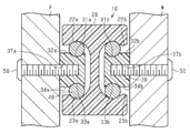
- FIG. 4 is a cross-sectional view taken along line 4-4 of FIG. 1, showing a state in which the slide rail unit of FIG. 1 is attached to furniture.
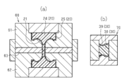
- the schematic diagram explaining the laminated structure of the outer rail of FIG. 7A is a diagram illustrating a method of manufacturing the outer rail of FIG. 2, and FIG. 7B is a diagram illustrating a method of manufacturing the inner rail of FIG. FIG.
- FIG. 8A is a diagram illustrating a test for measuring peel strength
- FIG. 8B is a graph showing actual measured values of peel strength.
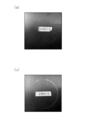
- 9(a) and 9(b) are photographs of the surface of the test piece after the test for abrasion durability.
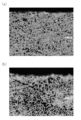
- 10(a) and 10(b) are photographs of the surface layer cross section of the test piece after the test for wear durability.
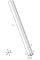
- the slide rail unit 10 of this embodiment will be described with reference to FIGS. 1 to 4.
- the slide rail unit 10 is used as a guide device that supports a drawer of furniture so as to be able to reciprocate.
- the example of the slide rail unit 10 attached to the right side of the drawer of furniture is demonstrated.
- the slide rail unit 10 will be defined as upward, downward, left, right, front and rear directions as shown in FIG.
- the terms “first”, “second”, etc. are used to distinguish similar components, and not necessarily in any particular contiguous or chronological order. It is not used to represent Further, in the specification, “left”, “right”, “front”, “rear”, “top”, “bottom”, “side (side)” “top”, “bottom”, “height”, etc. The terms are used to indicate their relative arrangement or configuration in the illustrated state and not necessarily their permanent relative position or their in-use position. Further, in the description of the stepwise numerical range, a range in which the upper limit and the lower limit are arbitrarily combined is also assumed.
- the slide rail unit 10 includes a long outer rail 20, two long inner rails 30, a plurality of balls 40, an outer rail side rack 81, and an inner rail side.
- the rack 82, the cage 83, and the pinion 84 are provided.
- the longitudinal direction of the slide rail unit 10, the outer rail 20, and the inner rail 30 is the front-back direction.
- One of the outer rail 20 and the inner rail 30 is the first rail, and the other is the second rail.
- the outer rail 20 is the first rail and the inner rail 30 is the second rail.
- the plurality of balls 40 are rolling elements arranged between the outer rail 20 and the inner rail 30.
- the outer rail side rack 81, the inner rail side rack 82, the cage 83, and the pinion 84 are arranged in order to arrange the plurality of balls 40 at predetermined intervals.
- the shape of the slide rail unit 10 is left-right asymmetrical, and is substantially point-symmetrical around the front, rear, left, and right center points.
- the number of the member or portion arranged on the left side of FIG. The numbers will be described by adding "b”.
- the left inner rail 30 is “30a”
- the right inner rail 30 is “30b”.
- both the inner rails 30a and 30b are collectively described, they are simply referred to as "inner rail 30".
- the outer rail 20 has a substantially H-shaped cross section.
- the outer rail 20 has a flat upper surface, a flat lower surface, and grooves 21a and 21b extending in the longitudinal direction.
- the grooves 21a and 21b are open on the left surface and the right surface of the outer rail 20, respectively. Further, the grooves 21a and 21b are open to the front surface and the rear surface of the outer rail 20.
- Each groove 21 has a first surface 22 facing downward and a second surface 23 facing upward.
- Each groove 21 has a curved surface that is smoothly connected from the first surface 22 to the second surface 23. This curved surface is the rolling surface of the ball 40.
- the ball 40 is arranged so as to roll along the curved surface along the longitudinal direction of the outer rail 20.
- FIG. 2 shows a state of the slide rail unit 10 in the process of being manufactured, more specifically, a state before a machining step of machining the outer rail 20, which will be described later.
- the outer rail 20 becomes the shape shown in FIG. 1 by going through the processing steps from the state of FIG.
- the shape of the outer rail 20 is left-right asymmetric, and is substantially point-symmetric with respect to the front, rear, left, and right center points.
- the outer rail 20 has a recessed portion 26b recessed upward from the first surface 22b and a recessed portion 27b recessed downward from the second surface 23b in the groove 21b.
- the recesses 26b and 27b extend forward from the vicinity of the center of the groove 21b in the longitudinal direction.
- the outer rail 20 has a recess 26a recessed upward from the first surface 22a and a recess 27a recessed downward from the second surface 23a in the groove 21a.
- the recesses 26a and 27a extend forward from the vicinity of the center of the groove 21a in the longitudinal direction.
- An outer rail side rack 81 is attached to each of the recesses 26 and 27.
- the inner rails 30a and 30b are assembled in the grooves 21a and 21b, respectively.
- the inner rail 30a has the same shape as the inner rail 30b.
- the inner rails 30a and 30b are assembled in the outer rail 20 in a state in which the upper, lower, left, right, front, and rear are inverted from each other. That is, the inner rails 30a and 30b are arranged so as to be point-symmetric with respect to the center of the outer rail 20 in the longitudinal direction.
- each inner rail 30 has a substantially rectangular cross-sectional shape.
- the inner rail 30b has an upper surface and a lower surface.
- the left half of the upper surface is the curved surface 31b, and the right half of the upper surface is the flat surface 32b.
- the right edge of the curved surface 31b is connected to the left edge of the flat surface 32b.
- the left half of the lower surface is the curved surface 33b, and the right half of the lower surface is the flat surface 34b.
- the right end edge of the curved surface 33b is connected to the left end edge of the flat surface 34b.
- the curved surfaces 31b and 33b are rolling surfaces of the ball 40.
- the ball 40 is arranged so as to roll along the longitudinal direction of the inner rail 30b.
- the inner rail 30b has a recess 35b recessed downward from the flat surface 32b and a recess 36b recessed upward from the flat surface 34b.
- the recesses 35b and 36b extend rearward from the vicinity of the center in the longitudinal direction.
- An inner rail side rack 82 is attached to each of the recesses 35b and 36b.
- the inner rail 30b has a plurality of holes 37b opened on the right side of the inner rail 30b.
- the plurality of holes 37b are arranged at intervals in the longitudinal direction. Since the inner rail 30a has the same shape as the inner rail 30b, the description thereof will be omitted.
- the inner rail 30a is fixed to the furniture main body F by a plurality of fixing members 50, such as screws, which are inserted into the plurality of holes 37a.
- the inner rail 30b is fixed to the drawer W by a plurality of fixing members 50, such as screws, which are respectively inserted in the plurality of holes 37b.
- the plurality of balls 40 are longitudinally arranged between the first surface 22 of the outer rail 20 and the curved surface 31 of the inner rail 30, and between the second surface 23 of the outer rail 20 and the curved surface 33 of the inner rail 30. It is arranged at intervals.
- a pinion 84 is arranged between the outer rail side rack 81 and the inner rail side rack 82. The pinion 84 meshes with the racks 81 and 82. When the inner rail 30 moves relative to the outer rail 20 along the longitudinal direction, the pinion 84 rotates along the racks 81 and 82 and the ball 40 rolls.
- the outer rail 20 and the inner rail 30 are a laminated body in which a plurality of sheet materials are laminated.
- One sheet material includes a plurality of sheets or layers made of fiber reinforced resin laminated in the thickness direction.
- the ball 40, the outer rail side rack 81, the inner rail side rack 82, the cage 83 and the pinion 84 are made of metal, for example.
- the ball 40 may be entirely made of metal.
- the ball 40 may include a synthetic resin core and a metal layer coated on the surface thereof. Alternatively, the ball 40 may include a metal core and a resin layer coated on the surface thereof.
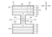
- FIGS. 5 and 6 are schematic diagrams illustrating a laminated structure.
- FIG. 5 schematically shows the structure of the outer rail 20
- FIG. 6 schematically shows the structure of the inner rail 30.
- the conventionally known fiber-reinforced resin can be used as the material of the outer rail 20 and the inner rail 30.
- fibers constituting the fiber-reinforced resin include carbon fibers, glass fibers, various ceramic fibers, boron fibers, metal fibers such as copper or stainless steel, amorphous fibers, organic fibers such as aromatic polyamide, or a mixture thereof. It is a woven fabric.
- carbon fiber has high flexural rigidity due to its high elastic modulus, and has a low specific gravity of about 1.8.
- a conventionally known thermosetting resin can be appropriately used as the reinforcing resin.
- thermosetting resins are epoxy resins, phenolic resins, polyester resins, vinyl ester resins, or unsaturated polyester resins.
- the outer rail 20 includes an outer body portion 24 that is a first body portion and an outer reinforcement portion 25 that is a first reinforcement portion.
- the outer body portion 24 includes a plurality of outer body sheets made of fiber reinforced resin and extending in the longitudinal direction of the outer rail 20. These outer body sheets are laminated in a direction intersecting the first surface 22 and the second surface 23, which are the rolling surfaces of the balls 40.
- the outer body sheet is the first body sheet.
- Outer surfaces, excluding the upper surface, the lower surface, the front surface, and the rear surface, of the plurality of outer surfaces of the outer body portion 24 are defined by the outer reinforcing portion 25.
- the outer reinforcing portion 25 is a first reinforcing portion and includes a plurality of reinforcing sheets made of fiber reinforced resin extending in the longitudinal direction. These reinforcing sheets are laminated in a direction intersecting with the outer surface of the outer body 24.
- the inner rail 30 includes an inner body portion 38 that is a second body portion and an inner reinforcement portion 39 that is a second reinforcement portion.
- the inner body portion 38 includes a plurality of inner body sheets made of fiber reinforced resin and extending in the longitudinal direction of the inner rail 30. These inner body sheets are laminated in a direction along the curved surfaces 31 and 33 which are rolling surfaces of the ball 40.
- the inner body sheet is the second body sheet.
- the inner reinforcing portion 39 defines an upper surface of the inner rail 30 including the curved surface 31 and a lower surface of the inner rail 30 including the curved surface 33.
- the inner reinforcing portion 39 includes a plurality of inner reinforcing sheets made of fiber reinforced resin and extending in the longitudinal direction. These inner reinforcing sheets are laminated in a direction intersecting the outer surface of the inner body portion 38.
- the inner rail 30b is shown in FIG. 6, the inner rail 30a also has the same structure as the inner rail 30b.
- Each sheet material forming the outer rail 20 and the inner rail 30 includes a plurality of laminated sheets or a plurality of layers. Each sheet is formed by cutting a prepreg sheet into a predetermined size. The prepreg sheet includes a plurality of fiber bundles aligned in one direction. Each fiber bundle is an assembly of filaments. A sheet in which the fibers of the sheet are oriented along the longitudinal direction of the outer rail 20 and the inner rail 30 is called a 0° oriented sheet, and a sheet in which the fibers of the sheet are oriented perpendicular to the longitudinal direction is oriented at 90°.
- the sheet in which the fibers of the sheet are oriented so as to intersect at 45° to the longitudinal direction is referred to as a ⁇ 45° oriented sheet (+45° oriented sheet and ⁇ 45° oriented sheet).
- the outer reinforcement 25 has a laminated structure that allows the balls 40 to roll smoothly. Further, the inner reinforcing portion 39 has a laminated structure in consideration of smoothly rolling the balls 40 and further reinforcing the rolling surface.
- FIG. 5 schematically shows a plurality of sheet materials 101 to 107 that form the outer rail 20.
- the laminated body in which the sheet materials 101 to 106 are laminated constitutes the outer body portion 24, and the sheet material 107 constitutes the outer reinforcing portion 25.
- All of the plurality of outer reinforcing sheets included in the sheet material 107 are 0° oriented sheets in which the fiber orientation direction is oriented along the longitudinal direction of the outer rail 20. That is, the orientation direction of the fibers of the outer reinforcing portion 25 coincides with the rolling direction of the ball 40. Therefore, the ball 40 rolls smoothly along the rolling surface defined by the outer reinforcing portion 25.
- the outer reinforcing sheet is a so-called light weight fiber reinforced resin having a smaller fiber basis weight than the outer body sheet.
- the fiber weight of the outer reinforcing sheet can be 10 to 180 g/m 2 .
- the fiber areal weight is increased.
- the larger the number of filaments contained in one fiber bundle the larger the fiber bundle diameter.
- the fiber areal weight is preferably 180 g/m 2 or less.
- the basis weight should be less than 150 g/m 2 .
- the fiber areal weight is preferably 25 g/m 2 or more, more preferably 50 g/m 2 or more.
- the fiber areal weight is 50 g/m 2 or more and 140 g/m 2 or less, not only the resin-coated surface of the ball but also the surface of the outer reinforcing portion 25 is worn even if the surface is a metal ball. The effect of suppressing
- FIG. 6 schematically shows a plurality of sheet materials 111 to 119 that form the inner rail 30.
- the laminated body of the sheet materials 111 to 118 constitutes the inner body portion 38, and the sheet material 119 constitutes the inner reinforcing portion 39.
- the plurality of inner reinforcing sheets included in the sheet material 119 are all 0° oriented sheets in which the fiber orientation direction is oriented along the longitudinal direction of the inner rail 30. Therefore, the ball 40 rolls smoothly along the rolling surface defined by the inner body portion 38.
- the fiber weight of the inner reinforcing sheet is preferably smaller than the fiber weight of the inner body sheet.
- the fiber areal weight of the inner reinforcing sheet is preferably in the same numerical range as the fiber areal weight of the outer reinforcing sheet. This reduces the sliding resistance with the ball 40. Further, abrasion of the surface of the inner reinforcing portion 39 due to rolling of the balls 40 is suppressed.
- the plurality of inner body sheets included in the sheet materials 111 to 119 are generally stacked in the direction along the curved surfaces 31 and 33.
- the direction along the curved surfaces 31 and 33 is the left-right direction shown in FIG. 6.
- a laminated body in which a plurality of sheets or sheet materials are laminated generally tends to cause warpage in the laminating direction.
- the inner reinforcing sheets of the inner body portion 38 are laminated in the left-right direction. Therefore, even if a warp occurs in the stacking direction, the plurality of fixing members 50 can suppress the warp of the inner body portion 38.
- the inner body sheets are laminated in the left-right direction, the stress from the balls 40 rolling along the curved surfaces 31 and 33 easily acts between the layers of the inner body sheet.
- the inner reinforcing sheets that define the curved surfaces 31 and 33 are stacked in a direction perpendicular to the stacking direction of the inner body sheets. Therefore, the laminated cross section of the sheet material is not exposed to the outside.
- the inner reinforcing portion 39 suppresses delamination of the inner body sheet that forms the inner body portion 38.
- the inner reinforcing portion 39 not only smoothly rolls the ball 40, but also reinforces the rolling surface.
- the outer body portion 24 and the inner body portion 38 are designed in a laminated structure that gives rigidity to the outer rail 20 and the inner rail 30, for example, bending rigidity and torsional rigidity. These laminated structures are also designed in consideration of suppressing warpage after molding and machining.
- the laminated body may have anisotropy due to the laminated structure and warpage may occur. Further, warpage may occur even if the shape of the laminated body is asymmetrical to the left and right, and warpage may occur also by performing machining after molding with a die.
- the properties of the outer rail 20, such as bending rigidity or torsional rigidity may change.
- the inner rail 30 the plurality of sheets forming the outer rail 20 and the inner rail 30 are laminated such that the orientation directions of the fibers are different in order to suppress the warpage of each of the sheets.
- the plurality of sheets are laminated so as to satisfy the following conditions.
- a plurality of regions in which a plurality of first sheet materials are laminated are included, and a plurality of first sheet materials constituting each region are laminated so that the orientation directions of fibers are symmetrical with respect to the center in the laminating direction. Being (symmetrically stacked).
- Each of the first sheet materials should include a plurality of sheets or a plurality of layers that are laminated (pseudo-isotropic lamination) so as to have isotropicity as a whole by the combination of the orientation directions of the fibers.
- ⁇ Condition 2-2> A second sheet material is laminated in a plurality of regions, and the second sheet material is laminated so as to have anisotropy (non-pseudo isotropic) in consideration of warpage due to machining after molding. Including a plurality of (laminated) sheets or a plurality of layers.
- the outer body 24 includes an upper region 100 above the groove 21, an intermediate region 200 sandwiched between the grooves 21 a and 21 b, and a lower region below the groove 21.
- the upper region 100, the middle region 200, and the lower region are examples of the plurality of first regions.
- Each of the sheet materials 106 and 107 includes two sheet materials that are symmetrically arranged.
- the sheet materials 102 to 106 are first sheet materials, and the sheet materials 101 and 107 are second sheet materials.
- Each sheet material includes a plurality of sheets or a plurality of layers stacked in the thickness direction.
- the upper region 100 includes the sheet materials 102 to 106 stacked in order from the top.
- the sheet materials 102 to 106 are stacked symmetrically with respect to the center of the sheet material 104 in the stacking direction (vertical direction) (symmetrical stacking). More specifically, the upper halves of the sheet materials 102, 103 and the sheet material 104 and the lower halves of the sheet materials 105, 106 and the sheet material 104 are symmetrical with respect to the center of the sheet material 104 in the thickness direction. ing.
- the lower region includes the sheet materials 106, 105, 104, 103 and 102 stacked in order from the top.
- the sheet materials 106 to 102 in the lower area are laminated vertically symmetrically with respect to the sheet materials 102 to 106 in the upper area 100 (symmetrical lamination).
- the two sheet materials included in the sheet material 106 are stacked in the left-right direction in a state of being abutted against each other at the center in the left-right direction. That is, the two sheet materials forming the sheet material 106 are laminated so as to be bilaterally symmetrical (symmetrical lamination).
- the orientations of a plurality of sheets (for example, four sheets) included in the sheet material 102 are 0° orientation, +45° orientation, ⁇ 45° orientation, and 90° orientation in order from the top.
- the orientations of the plurality of sheets (for example, four sheets) included in the sheet material 103 are 90° orientation, ⁇ 45° orientation, +45° orientation, and 0° orientation in this order from the top.
- the orientations of the plurality of sheets (for example, three sheets) included in the upper half of the sheet material 104 are 0° orientation, ⁇ 45° orientation, and +45° orientation in this order from the top.
- the orientations of the plurality of sheets (for example, four sheets) included in the sheet material 105 are 0° orientation, +45° orientation, ⁇ 45° orientation, and 90° orientation in this order from the top.
- the orientation of the plurality of sheets (for example, four sheets) included in the sheet material 106 is 90° orientation, ⁇ 45° orientation, +45° orientation, and 0° orientation in this order from the top.
- the orientations of the plurality of sheets (for example, three sheets) included in the lower half of the sheet material 104 are +45° orientation, ⁇ 45° orientation, and 0° orientation in this order from the top.
- each sheet material has a plurality of sheets (that is, a multiple of 4 or 3) as one set of 4 or 3 sheets laminated in the above orientation. Sheet) is preferable.
- a plurality of sheets having the same orientation may be a single layer and a plurality of layers having different orientations may be laminated.
- the sheet material 102 includes a plurality of sheets (for example, four sheets or four layers) that are a combination of 0° orientation, 90° orientation, and ⁇ 45° orientation. Thereby, the sheet materials 102 are laminated so as to have isotropicity as a whole. Similar to the sheet material 102, the sheet materials 103, 105 and 106 are also laminated so as to have isotropicity as a whole. Therefore, the sheet materials 102 to 106 are the first sheet materials that satisfy the condition 2-1.
- the plurality of first sheets cut out from the prepreg sheet which is an anisotropic material are laminated so as to have isotropicity, and further the plurality of first sheet materials are symmetrically laminated to form a mold. The occurrence of warpage after being suppressed is suppressed.
- the outer rail 20 having a left-right asymmetrical shape it is machined, for example, cut and drilled after being molded with a mold. Even a laminated body satisfying the conditions 1 and 2-1 may warp due to the asymmetrical shape and warp due to machining.
- the outer body portion 24 of the present embodiment further includes a second sheet material for further anisotropy in the laminated body satisfying the condition 1 and the condition 2-1 so as to further satisfy the condition 2-2. It is stacked.
- the plurality of sheets included in the sheet materials 101 and 104 in the upper region 100 are laminated so as to have anisotropy. Due to the presence of the sheet materials 101 and 104, the upper region 100 has anisotropy as a whole.
- a plurality of sheets (for example, three sheets or three layers) included in the sheet material 101 have 0° orientation, 90° orientation, and 0° orientation in this order from the top, and a plurality of sheets (for example, six sheets) included in the sheet material 104.
- the sheets of () are, in order from the top, 0° orientation, ⁇ 45° orientation, +45° orientation, +45° orientation, ⁇ 45° orientation, and 0° orientation.
- the outer body portion 24 has anisotropy as a whole.
- a plurality of sheet materials and sheets included in the inner body portion 38 are also laminated so as to satisfy the above-mentioned condition 1, condition 2-1 and condition 2-2.
- the inner body portion 38 includes an inner region 300 sandwiched between the curved surfaces 31b and 33b and an outer region 400 sandwiched between the flat surfaces 32b and 34b. Areas 300 and 400 are examples of a plurality of second areas.
- the sheet materials 111 to 115 in the inner region 300 are laminated such that the fiber orientation directions are bilaterally symmetrical with respect to the center of the sheet material 113 in the laminating direction (horizontal direction) ( Symmetrical stacking). More specifically, the left halves of the sheet members 111 and 112 and the sheet member 113 and the right halves of the sheet members 114 and 115 and the sheet member 113 are symmetrical with respect to the center of the sheet member 113 in the left-right direction. ing.
- the sheet materials 116 and 117 in the outer region 400 are laminated such that the orientation directions of the fibers are bilaterally symmetrical with respect to the boundary between the sheet materials 116 and 117.
- the plurality of sheets included in the sheet materials 112 and 114 in the inner area 300 are laminated so as to have isotropicity, and the plurality of sheets included in the sheet materials 116 and 117 in the outer area 400 are included.
- the sheets are laminated so as to be isotropic.
- the inner rail 30 has a left-right asymmetrical shape, like the outer rail 20. Further, when the inner rail 30 is manufactured, warping occurs because it is machined, for example, cut and drilled after being molded with a mold. In order to suppress such warpage, a plurality of sheets included in the sheet materials 111, 113, and 115 in the inner region 300 are laminated so as to have anisotropy so as to satisfy the condition 2-2.
- the inner region 300 as a whole has anisotropy due to the presence of the sheet materials 111, 113, and 115 that are the second sheet materials.
- the outer region 400 is provided with the sheet material 118 that is the second sheet material, so that the entire outer area 400 has anisotropy. As a result, the inner body portion 38b has anisotropy as a whole.
- the method for manufacturing the outer rail 20 includes a cutting process, a laminating process, a molding process, and a processing process.
- a cutting step a plurality of sheets are formed by appropriately cutting a prepreg sheet in which the fiber reinforced resin is aligned in one direction into a predetermined size.
- the laminating step a plurality of sheets are laminated to form a sheet material, and further a plurality of sheet materials are laminated.
- the molding step a plurality of laminated sheet materials are placed in a mold to mold a molded body.
- the processing step the molded body taken out from the mold is subjected to mechanical processing, for example, cutting processing and drilling processing.
- a plurality of outer body sheets are laminated so that the outer body portion 24 has the above-mentioned laminated structure.
- a plurality of outer reinforcing sheets forming the outer reinforcing portion 25 are laminated and arranged in advance on the inner surface of the mold 60 shown in FIG. 7A.
- a plurality of inner body sheets are laminated so that the inner body portion 38 has the above-described laminated structure.
- a plurality of inner reinforcing sheets constituting the inner reinforcing portion 39 are laminated and arranged in advance on the inner surface of the mold 70 shown in FIG. 7B.
- the outer reinforcing sheet and the inner reinforcing sheet are laminated in consideration of the machining allowance in the polishing step in the subsequent processing step.
- a plurality of laminated outer body sheets are placed in a mold 60 in which a plurality of outer reinforcing sheets are placed, and the die is clamped.
- a mold body (laminate) in which a plurality of outer body sheets and a plurality of outer reinforcing sheets are integrated is molded by clamping and heating the mold 60.
- the mold 60 has an undercut portion for forming the groove 21 of the outer rail 20. Therefore, it is not necessary to cut the shape of the groove 21 in the processing step described later, or it is possible to reduce the portion to be cut.
- the mold 60 may include a slide mold 63 in addition to the upper mold 61 and the lower mold 62, as shown in FIG. 7A, for example. In this case, the molded body can be easily demolded.
- a plurality of laminated inner body sheets are arranged in a mold 70 in which a plurality of inner reinforcing sheets are arranged, and the mold is clamped.
- a molded body (laminate) in which a plurality of inner body sheets and a plurality of inner reinforcing sheets are integrated is molded.
- recesses 26 and 27 for mounting the outer rail side rack 81 are formed on the outer rail 20, and recesses 35 and 36 for mounting the inner rail side rack 82 are formed on the inner rail 30. Further, if necessary, a cutting process for adjusting the shape of the groove 21 of the outer rail 20 is performed.
- the machining includes a boring process for boring a hole 37 and a polishing process for polishing the surface of the outer rail 20 and the surface of the inner rail 30.
- the outer rail 20 and the inner rail 30 are entirely made of fiber reinforced resin.
- the inner rail 30 is arranged in the groove 21 of the outer rail 20.
- a plurality of balls 40 are arranged between the first surface 22 of the outer rail 20 and the curved surface 31 of the inner rail 30, and between the second surface 23 of the outer rail 20 and the curved surface 33 of the inner rail 30.
- the first surface 22 and the second surface 23 are first opposing surfaces
- the curved surfaces 31 and 33 are second opposing surfaces.
- the first and second facing surfaces that are in contact with the balls 40 are defined by the reinforcing portion (outer reinforcing portion 25 and inner reinforcing portion 39) in which a plurality of reinforcing sheets made of fiber reinforced resin are laminated.
- the plurality of reinforcing sheets forming the outer reinforcing portion 25 and the inner reinforcing portion 39 are made of fiber reinforced resin and extend in the longitudinal direction of the outer rail 20 and the inner rail 30. Since these reinforcing sheets are laminated in the direction perpendicular to the facing surface, the laminated cross sections of the plurality of reinforcing sheets are not exposed on the facing surface. Therefore, the sliding resistance of the ball 40 on the facing surface can be reduced.
- the plurality of inner body sheets forming the inner body portion 38 are made of fiber reinforced resin and extend in the longitudinal direction. These inner body sheets are stacked in the direction along the curved surfaces 31 and 33 on which the balls 40 roll. Further, the plurality of inner reinforcing sheets forming the inner reinforcing portion 39 defining the curved surfaces 31 and 33 are made of fiber reinforced resin and extend in the longitudinal direction. These inner reinforcing sheets are laminated in a direction perpendicular to the curved surfaces 31, 33. That is, the laminating direction of the inner reinforcing sheet forming the inner reinforcing portion 39 is perpendicular to the laminating direction of the inner body sheet forming the inner body portion 38.
- the stress from the ball 40 acts on the opposing surfaces (curved surfaces 31, 33), delamination of the inner body sheet is suppressed. Further, the presence of the inner reinforcing portion 39 increases the strength of the curved surfaces 31 and 33 which are the rolling surfaces of the ball 40.
- the inner reinforcement sheet forming the inner reinforcement portion 39 has a smaller fiber basis weight than the inner body sheet forming the inner body portion 38.
- the outer reinforcement sheet forming the outer reinforcement portion 25 has a smaller fiber basis weight than the outer body sheet forming the outer body portion 24.
- the outer rail 20 and the inner rail 30 having the left-right asymmetrical shape have a region in which a plurality of first sheet materials are symmetrically stacked and a second sheet material in which a plurality of sheets are anisotropically stacked. Including. Therefore, the occurrence of warpage in the outer rail 20 and the inner rail 30 can be suppressed. In addition, it is possible to suppress the occurrence of warpage due to machining after molding with a mold. Therefore, dimensional accuracy can be improved even with an asymmetric rail.
- the mold 60 used when manufacturing the outer rail 20 includes an upper mold 61, a lower mold 62, and a slide mold 63. Therefore, even if the mold 60 has an undercut portion for forming the groove 21 of the outer rail 20, the mold can be easily removed.
- the above embodiments can be modified as follows.
- the above-described embodiments and the following modified examples can be applied in combination with each other within a technically consistent range.
- the shapes of the outer rail 20 and the inner rail 30 can be arbitrarily changed.
- two long rails corresponding to each other may have a rectangular cross-sectional shape, and balls as rolling elements may be arranged between the two planes.
- the outer rail 20 does not have to have one of the grooves 21a and 21b.
- one inner rail 30 may be assembled in one groove 21 of the outer rail 20 so as to be relatively movable.
- the slide rail unit 10 may be applied not only to a guide device for pulling out furniture, but also to an ottoman installed on a train or an aircraft seat.
- -Parts of the outer rail 20 and the inner rail 30 may be formed of a metal material.
- only the outer reinforcing portion 25 and the inner reinforcing portion 39 that define the facing surface may be made of fiber reinforced resin, and the other portions may be made of metal. Even in this case, the weight of the slide rail unit 10 can be reduced as compared with the case where the whole is made of a metal material.
- Only one of the outer reinforcing portion 25 and the inner reinforcing portion 39 may be made of fiber reinforced resin, and the other portions may be made of metal. Even in this case, the weight of the slide rail unit 10 can be reduced as compared with the case where the whole is made of a metal material.
- the slide rail unit 10 does not need to include the outer reinforcing portion 25.
- the outer body sheets made of fiber reinforced resin that define the rolling surfaces (the first surface 22 and the second surface 23) of the outer rail 20 are stacked in a direction perpendicular to the rolling surfaces. Therefore, the outer body sheet is unlikely to be affected by the stress from the balls 40.
- the stacking direction of the inner body sheets that form the inner body portion 38 may be perpendicular to the rolling surfaces (curved surfaces 31, 33).
- the outer reinforcing portion 25 may be arranged only on the portion of the first surface 22 and the second surface 23 on which the ball 40 rolls.
- the inner reinforcing portion 39 may not define the flat surfaces 32 and 34, but may define only the curved surfaces 31 and 33.
- the laminated structure of the outer rail 20 and the laminated structure of the inner rail 30 can be arbitrarily changed. For example, if the above condition 1, condition 2-1 and condition 2-2 are satisfied and the laminated structure is capable of suppressing the warp of the outer rail 20 and the inner rail 30, any sheet material is laminated so as to have anisotropy. You may.
- the rolling element for relatively moving the outer rail 20 and the inner rail 30 is not limited to the ball 40, but may be, for example, a roller. (Verification example 1) The inventor verified the effect of reinforcement by disposing the inner reinforcement portion 39 on the inner rail 30.
- a test piece imitating the inner rail was molded.
- the test piece has the inner reinforcing portion 39 on the upper surface but does not have the inner reinforcing portion 39 on the lower surface.
- the molded inner rail was divided at the middle in the vertical direction to obtain two divided pieces. The two pieces are shown in FIG. 8(a).
- the split piece on the left side of FIG. 8A is a verification piece having an inner reinforcing portion 39 defining the curved surface 31, and the split piece on the right side of FIG. 8A is an inner reinforcing portion defining the curved surface 33. Control piece without 39.
- the ball 40 was placed on the curved surfaces 31 and 33 of the two divided pieces, and a load was applied from above with the ball 40 in contact with the bottom of the rolling surface at one point. The load applied was gradually increased, and the displacement amount (mm) of the inner body sheet at the inner body portion 38 at that time was measured.
- FIG. 8B the horizontal axis represents the displacement amount (mm) and the vertical axis represents the test force (N).
- the result of the verification piece having the inner reinforcing portion 39 is shown by a solid line in FIG. 8B, and the result of the control piece having no inner reinforcing portion 39 is shown by a dotted line in FIG. 8B. According to FIG. 8B, it can be seen that the verification piece having the inner reinforcing portion 39 has a strength of about 700 N higher than that of the control piece.
- the sheet material forming the reinforcing portion is formed of a so-called light weight fiber reinforced resin having a smaller fiber basis weight than the sheet material forming the main body portion.
- the surface is made smooth and the rolling of the balls 40 is made smooth, and the wear of the surface is suppressed.
- Verification Example 2 it was verified how smooth the surface is and how much the surface wear is suppressed by changing the fiber areal weight of the fiber reinforced resin of the test piece.
- the two test pieces have different basis weights because the surface layer of 0.3 mm is formed of different prepreg sheets.
- the other parts of the two test pieces have the same structure.
- ⁇ Measurement of surface roughness> The surface roughness of two test pieces was measured. The measuring method of the surface roughness is as follows.
- Table 1 shows the measurement results of surface roughness.
- the amount of wear is considered to be equivalent to the difference in height of the bearing races of the test piece before and after the test (hereinafter referred to as wear depth). Therefore, the wear depth of the two test pieces was measured with a laser microscope and used as an index of wear durability.
- the test machine, test conditions, and measurement method used are as follows.
- ⁇ Abrasion durability tester Thrust tester (FJ-5HL)
- Bearing material SUJ2 (Use 6 bearings per test piece, use new bearing for each test piece)
- -Test method Three test points were extracted from the bearing race. The wear depth at each test location was measured with a laser microscope. For each test piece, the average value of the measured values at three locations was calculated.
- FIGS. 9(a) and 9(b) show surface photographs of the test piece after the test
- FIGS. 10(a) and 10( show photographs of surface cross-sections of the test piece after the test taken with a microscope. Shown in b). The microscope photograph was taken at a magnification of 1000 times using VHX-6000 as a device to be used.
- 9(a) and 10(a) are photographs of the first test piece having a basis weight of 100 g/m 2
- FIGS. 9(b) and 10(b) are second tests having a basis weight of 150 g/m 2 .
- a photo of one piece is a photo of one piece.
- the cross section of the carbon fiber of each test piece and the resin appear.
- the carbon fibers of the first test piece in FIG. 10(a) are arranged more evenly than the carbon fibers of the second test piece in FIG. 10(b).
- the sheet of the second test piece contains a larger number of fiber bundles than the sheet of the first test piece due to the increased fiber basis weight. Therefore, the number of boundary portions between fiber bundles is large. Furthermore, since the fibers of the sheet of the second test piece are clogged, it is difficult to arrange the fibers uniformly. For these reasons, it is considered that the first test piece in which the carbon fibers are arranged more uniformly exerted the stress when the load of the bearing was applied.
Landscapes
- Chemical & Material Sciences (AREA)
- Engineering & Computer Science (AREA)
- Materials Engineering (AREA)
- Chemical Kinetics & Catalysis (AREA)
- Manufacturing & Machinery (AREA)
- Health & Medical Sciences (AREA)
- Inorganic Chemistry (AREA)
- Medicinal Chemistry (AREA)
- Polymers & Plastics (AREA)
- Organic Chemistry (AREA)
- General Engineering & Computer Science (AREA)
- Mechanical Engineering (AREA)
- Bearings For Parts Moving Linearly (AREA)
- Drawers Of Furniture (AREA)
Abstract
スライドレールユニットは、長尺状の第1のレールであって、前記第1のレールの長手方向に沿って延びる第1対向面を有する第1のレールと、前記第1のレールに沿って延びる長尺状の第2のレールであって、前記第1対向面に対向する第2対向面を有する第2のレールと、前記第1対向面と前記第2対向面との間に配置される転動体と、を備える。前記第2のレールは、前記第1のレールに対して相対移動可能に組み付けられ、前記第1対向面及び前記第2対向面のうち少なくとも一方の対向面は、繊維強化樹脂材料で形成された補強部によって画定されている。
Description
本開示は、スライドレールユニット及びスライドレールユニットの製造方法に関する。
典型的なスライドレールユニットの例は、家具の引き出しまたはテーブルを進退移動可能に支承する案内装置である。こうしたスライドレールユニットは、電車または航空機の座席に配置されるオットマンに適用されることがある。オットマンは、乗客が足を載せるために使用される。
特許文献1は、家具に使用されるスライドレールユニットを開示している。このスライドレールユニットは、アウタレールと、センターレールと、インナレールと、複数のボールと、ケージとを備えている。アウタレールは、家具本体に固定されて、家具の引き出しのスライド部に適用される。インナレールは、アウタレールに対して相対移動可能に組み付けられる。インナレールは、引き出しに固定されて、センターレール内に相対移動可能に組み付けられる。複数のボールは、レールの間に配置された転動体である。ケージは、ボールを所定の間隔で配列させるために配置される。引き出しを家具本体から引き出すときには、複数のボールの転動により、インナレールがセンターレールから引き出されるとともにセンターレールがアウタレールから引き出される。その結果、引き出しが家具本体から突出した状態となる。引き出しを家具本体内に押し入れるときには、複数のボールの転動により、インナレールがセンターレール内に収容されるとともにセンターレールがアウタレール内に収容される。その結果、引き出しは家具本体内に収容された状態に戻る。
こうしたスライドレールユニットには、最大量引き出された状態での使用に耐えるための強度及び剛性が要求されるとともに、引き出し操作をスムーズにするための寸法精度が要求される。そのため、特許文献1に記載のスライドレールユニットが備えるアウタレール、センターレール及びインナレールは、SPCCのような金属板材をロールフォーミング加工することによって精密に成形されている。
一方で、こうした家具は、軽量化することが要望される。特に複数の引き出しを有する家具において、各引き出しに取り付けられるスライドレールユニットを軽量化すると、家具全体の軽量化に繋がる。また、電車または航空機の座席に配置されるオットマンのような設備に適用されるスライドレールユニットを軽量化することは、燃費効率の向上にも繋がる。
本開示は、スライドレールユニットを軽量化することを目的としている。
本開示の一態様に係るスライドレールユニットは、長尺状の第1のレールであって、前記第1のレールの長手方向に沿って延びる第1対向面を有する第1のレールと、前記第1のレールに沿って延びる長尺状の第2のレールであって、前記第1対向面に対向する第2対向面を有する第2のレールと、前記第1対向面と前記第2対向面との間に配置される転動体と、を備える。前記第2のレールは、前記第1のレールに対して相対移動可能に組み付けられる。前記第1対向面及び前記第2対向面のうち少なくとも一方の対向面は、繊維強化樹脂材料で形成された補強部によって画定されている。
本開示の一態様に係る方法は、スライドレールユニットの製造方法である。前記スライドレールユニットは、第1のレールと、前記第1のレールに沿って延びる第2のレールと、前記第1のレールと前記第2のレールとの間に配置される複数の転動体と、を備える。前記方法は、繊維強化樹脂製の複数のシートを積層することと、積層された前記複数のシートを金型に配置して成形体を成形することと、含む。前記複数のシートを積層することは、前記複数のシートの積層方向における中央を基準として、繊維の配向方向が対称となるように、前記複数のシートを積層することを含む。
以下、本実施形態のスライドレールユニット10を図1~図4に従って説明する。
スライドレールユニット10は、家具の引き出しを往復移動可能に支承する案内装置として使用される。以下では、家具の引き出しの右側に取り付けられたスライドレールユニット10の例について説明する。説明の便宜上、スライドレールユニット10について、図1に示すように上、下、左、右、前及び後の各方向を規定する。
スライドレールユニット10は、家具の引き出しを往復移動可能に支承する案内装置として使用される。以下では、家具の引き出しの右側に取り付けられたスライドレールユニット10の例について説明する。説明の便宜上、スライドレールユニット10について、図1に示すように上、下、左、右、前及び後の各方向を規定する。
明細書および請求の範囲において、「第1」、「第2」などの用語は、同様な構成要素を区別するために使用するものであり、必ずしも特定の連続する、または時系列に従った順番を表すために使用するのではない。また、明細書において、「左」、「右」、「前」、「後」、「頂」、「底」、「側(面)」「上」、「下」、「高さ」などの用語は、図示された状態での相対的な配置または構成を示すために使用するものであり、必ずしも恒久的な相対位置または使用時の位置を表わすものではない。また、段階的な数値範囲の記載においては、上限及び下限を任意に組み合わせた範囲も想定される。
明細書及び/又は特許請求の範囲に開示された全ての特徴は、当初の開示の目的のために、ならびに、実施形態及び/又は特許請求の範囲における特徴の組み合わせから独立して特許請求の範囲に記載の発明を限定する目的のために、互いに別個にかつ独立して開示されることを意図したものである。全ての数値範囲又は構成要素の集合を表す記載は、当初の開示の目的のため、ならびに特許請求の範囲に記載の発明を限定する目的のために、特に数値範囲の限定として、全ての可能な中間値又は中間的構成要素を開示するものである。
開示された実施形態は、本発明の範囲を限定するものと見なされるべきではなく、同等の機能または同じ機能を果たす別個の実施形態の特徴は、補正された請求項の範囲内で開示された実施形態間で交換することができる。端点による数値範囲の列挙は、その範囲内のすべての数を含む。例えば、1から5は、1、1.5、2、2.75、3、3.80、4、および5を含む。
図1及び図4に示すように、スライドレールユニット10は、長尺状のアウタレール20と、長尺状の2つのインナレール30と、複数のボール40と、アウタレール側ラック81と、インナレール側ラック82と、ケージ83と、ピニオン84とを備えている。スライドレールユニット10、アウタレール20及びインナレール30の長手方向は前後方向である。アウタレール20及びインナレール30のいずれか一方が第1のレールであり、他方が第2のレールである。本実施形態では、アウタレール20が第1のレールであり、インナレール30が第2のレールである。複数のボール40は、アウタレール20とインナレール30の間に配置される転動体である。アウタレール側ラック81、インナレール側ラック82、ケージ83及びピニオン84は、複数のボール40を所定間隔で配置するために配置される。
スライドレールユニット10の形状は、左右非対称であって、前後左右の中心点を中心としてほぼ点対称である。以下では、右と左にそれぞれ配置される2つの部材または部分のうち、図1の左側に配置される部材または部分の番号には「a」を付し、右側に配置される部材または部分の番号には「b」を付して説明する。例えば、左側のインナレール30は「30a」であり、右側のインナレール30は「30b」である。また、インナレール30a,30bの両方をまとめて説明する場合には単に「インナレール30」とする。
図2に示すように、アウタレール20は略H形状の断面を有する。アウタレール20は、平坦な上面と、平坦な下面と、長手方向に延びる溝21a,21bとを有する。溝21a,21bは、それぞれアウタレール20の左面と右面とに開口している。さらに、溝21a,21bは、アウタレール20の前面と後面とに開口している。各溝21は、下方を向いた第1面22と、上方を向いた第2面23とを有する。各溝21は、第1面22から第2面23までなめらかにつながった湾曲面を有する。この湾曲面は、ボール40の転動面である。ボール40は、この湾曲面に沿って、アウタレール20の長手方向に沿って転動するように配置される。
図2は、スライドレールユニット10の製造途中の状態、より詳細には、後に説明する、アウタレール20を機械加工する加工工程前の状態を示す。アウタレール20は、図2の状態から加工工程を経ることによって、図1に示す形状になる。アウタレール20の形状は、左右非対称であって、前後左右の中心点を中心としてほぼ点対称である。
図1に示すように、アウタレール20は、溝21b内において、第1面22bから上方に凹む凹部26bと、第2面23bから下方に凹む凹部27bとを有する。凹部26b,27bは、長手方向における溝21bの中央付近から前方に向けて延びる。また、アウタレール20は、溝21a内において、第1面22aから上方に凹む凹部26aと、第2面23aから下方に凹む凹部27aとを有する。凹部26a,27aは、長手方向における溝21aの中央付近から前方に向けて延びる。各凹部26,27には、アウタレール側ラック81が取り付けられる。
図1及び図3に示すように、インナレール30a,30bは、それぞれ溝21a,21b内に組み付けられている。インナレール30aはインナレール30bと同じ形状を有する。インナレール30a,30bは、互いに上下左右前後が反転した状態で、アウタレール20内に組み付けられている。つまり、インナレール30a,30bは、アウタレール20の長手方向における中央を中心として点対称となるように配置されている。
図3に示すように、各インナレール30は、略矩形の断面形状を有する。インナレール30bは上面と下面とを有する。上面の左半分は湾曲面31bであり、上面の右半部分は平坦面32bである。湾曲面31bの右端縁は平坦面32bの左端縁とつながっている。下面の左半分は湾曲面33bであり、下面の右半分は平坦面34bである。湾曲面33bの右端縁は平坦面34bの左端縁とつながっている。湾曲面31b,33bはボール40の転動面である。ボール40は、インナレール30bの長手方向に沿って転動するように配置される。
インナレール30bは、平坦面32bから下方に凹む凹部35bと、平坦面34bから上方へ凹む凹部36bとを有する。凹部35b,36bは、長手方向における中央付近から後方に向けて延びる。各凹部35b,36bには、インナレール側ラック82が取り付けられる。インナレール30bは、インナレール30bの右面に開口する複数の穴37bを有する。複数の穴37bは、長手方向に間隔をあけて配置されている。インナレール30aはインナレール30bと同じ形状を有するため、説明は省略する。
図4に示すように、インナレール30aは、複数の穴37aにそれぞれに挿入された複数の固定部材50、例えばネジによって、家具本体Fに固定されている。インナレール30bは、複数の穴37bにそれぞれに挿入された複数の固定部材50、例えばネジによって、引き出しWに固定されている。
複数のボール40は、アウタレール20の第1面22とインナレール30の湾曲面31との間、及び、アウタレール20の第2面23とインナレール30の湾曲面33との間に、長手方向に間隔をあけて配置されている。アウタレール側ラック81とインナレール側ラック82との間には、ピニオン84が配置されている。ピニオン84はラック81,82と噛合している。インナレール30が長手方向に沿ってアウタレール20に対して相対移動するときには、ピニオン84がラック81,82に沿って回転するとともにボール40が転動する。
アウタレール20及びインナレール30は、複数のシート材が積層された積層体である。一のシート材は、厚さ方向に積層された繊維強化樹脂製の複数のシートまたは複数の層を含む。ボール40、アウタレール側ラック81、インナレール側ラック82、ケージ83及びピニオン84は、例えば、金属製である。ボール40は、全体が金属製であってもよい。ボール40は、合成樹脂製のコアと、その表面にコーティングされた金属層とを含んでもよい。あるいは、ボール40は、金属製のコアと、その表面にコーティングされた樹脂層とを含んでもよい。
次に、アウタレール20及びインナレール30の積層構造及び作用について、図5及び図6に従って説明する。図5及び図6は積層構造について説明する模式図である。図5はアウタレール20の構造を模式的に示しており、図6はインナレール30の構造を模式的に示している。
アウタレール20及びインナレール30の材料には、従来から知られた繊維強化樹脂を使用することができる。繊維強化樹脂を構成する繊維の例は、炭素繊維、ガラス繊維、各種セラミックス繊維、ボロン繊維、銅またはステンレスのような金属繊維、アモルファス繊維、芳香族ポリアミドのような有機繊維、あるいは、それらの混織物である。特に、炭素繊維は、高い弾性率に起因する高い曲げ剛性を備え、比重が1.8前後と軽い。また、強化樹脂としては、従来公知の熱硬化性樹脂を適宜使用することができる。熱硬化性樹脂の例は、エポキシ樹脂、フェノール樹脂、ポリエステル樹脂、ビニルエステル樹脂、または不飽和ポリエステル樹脂である。
図5に示すように、アウタレール20は、第1本体部であるアウタ本体部24と、第1補強部であるアウタ補強部25とを備える。アウタ本体部24は、アウタレール20の長手方向に延びる繊維強化樹脂製の複数のアウタ本体シートを含む。これらアウタ本体シートは、ボール40の転動面である第1面22及び第2面23に対して交差する方向に積層されている。アウタ本体シートは、第1本体シートである。
アウタ本体部24が有する複数の外面のうち、上面、下面、前面及び後面を除く外面は、アウタ補強部25によって画定されている。アウタ補強部25は第1補強部であり、長手方向に延びる繊維強化樹脂製の複数の補強シートを含む。これら補強シートは、アウタ本体部24の外面に対して交差する方向に積層されている。
図6に示すように、インナレール30は、第2本体部であるインナ本体部38と、第2補強部であるインナ補強部39とを備える。インナ本体部38は、インナレール30の長手方向に延びる繊維強化樹脂製の複数のインナ本体シートを含む。これらインナ本体シートは、ボール40の転動面である湾曲面31,33に沿う方向に積層されている。インナ本体シートは、第2本体シートである。
インナ本体部38が有する複数の外面のうち、左面、右面、前面及び後面を除く外面はインナ補強部39によって画定されている。より詳細には、インナ補強部39は、湾曲面31を含むインナレール30の上面と、湾曲面33を含むインナレール30の下面とを画定している。インナ補強部39は、長手方向に延びる繊維強化樹脂製の複数のインナ補強シートを含む。これらインナ補強シートは、インナ本体部38の外面に対して交差する方向に積層されている。図6ではインナレール30bを示しているが、インナレール30aもインナレール30bと同様の構造を有する。
アウタレール20及びインナレール30を構成する各シート材は、積層された複数のシートまたは複数の層を含む。各シートは、プリプレグシートを所定の大きさに切ることによって形成される。プリプレグシートは、一方向に引き揃えられた複数の繊維束を含む。各繊維束は、フィラメントの集合体である。シートの繊維がアウタレール20及びインナレール30の長手方向に沿って配向されているシートを0゜配向のシートといい、シートの繊維が長手方向に対して垂直に配向されているシートを90゜配向のシートといい、シートの繊維が長手方向に対して45゜で交差するように配向されているシートを±45゜配向のシート(+45゜配向のシート及び-45゜配向のシート)という。これらシートを適宜に組み合わせて積層することによって、異なる性質のシート材が形成される。
アウタ補強部25は、ボール40を滑らかに転動させることを考慮した積層構造を有する。また、インナ補強部39は、ボール40を滑らかに転動させるとともに転動面をより補強することを考慮した積層構造を有する。
図5では、アウタレール20を構成する複数のシート材101~107を模式的に示している。シート材101~106のを積層した積層体がアウタ本体部24を構成し、シート材107がアウタ補強部25を構成する。
シート材107が含む複数のアウタ補強シートは、すべて、繊維の配向方向がアウタレール20の長手方向に沿って配向されている、0゜配向のシートである。すなわち、アウタ補強部25の繊維の配向方向はボール40の転動方向と一致している。そのため、ボール40はアウタ補強部25が画定する転動面に沿って、滑らかに転動する。
また、アウタ補強シートは、アウタ本体シートより繊維目付量が少ない、いわゆる薄目付の繊維強化樹脂である。例えばアウタ本体シートの繊維目付量が300g/m2である場合に、アウタ補強シートの繊維目付量を10~180g/m2とすることができる。一の繊維束に含まれるフィラメントの数を多くすると、繊維目付量が多くなる。一の繊維束に含まれるフィラメントの数を多くすると、繊維束径が大きくなる。繊維束径の大きな繊維束を並べてシートにすると、その表面の粗さは、繊維束径が小さな繊維束を並べたシートの表面の粗さより、粗くなる。そのため、表面の粗度を小さくするためには、繊維目付量を180g/m2以下にするとよい。
さらに、目付量が多いと、シートが厚くなるので、シートに含まれる繊維が均一に並びにくくなる。そうすると、繊維束は目付量が少ない場合よりも均一に並び難くなる。これにより、目付量が多い場合は少ない場合よりもボール40による荷重を均一に受け難くなるため、シートが摩耗しやすくなる。樹脂の強度は繊維の強度より弱いためである。シートの耐摩耗性を高くするには、目付量を150g/m2未満にするとよい。
ただし、繊維目付量が少なくなると、その分、樹脂の含有量が高くなることがある。よって、繊維目付量が少なくなりすぎると、シートは摩耗しやすくなる。そのため、繊維目付量は25g/m2以上にすることが好ましく、50g/m2以上にすることがより好ましい。特に、繊維目付量が50g/m2以上140g/m2以下であると、表面が樹脂コーティングされたボールだけでなく、表面が金属製のボールであっても、アウタ補強部25の表面の摩耗を抑制する効果が大きい。
図6では、インナレール30を構成する複数のシート材111~119を模式的に示している。シート材111~118の積層体はインナ本体部38を構成し、シート材119はインナ補強部39を構成する。
シート材119が含む複数のインナ補強シートは、すべて、繊維の配向方向がインナレール30の長手方向に沿って配向されている、0゜配向のシートである。そのため、ボール40はインナ本体部38が画定する転動面に沿って、滑らかに転動する。
インナ補強シートの繊維目付量は、インナ本体シートの繊維目付量より少ないことが好ましい。例えば、インナ補強シートの繊維目付量は、アウタ補強シートの繊維目付量と同じ数値範囲であることが好ましい。これにより、ボール40との摺動抵抗が軽減される。また、ボール40の転動によるインナ補強部39の表面の摩耗が抑制される。
シート材111~119に含まれる複数のインナ本体シートは、概ね、湾曲面31,33に沿う方向に積層されている。ここで、湾曲面31,33に沿う方向とは、図6に示す左右方向である。複数のシートまたはシート材を積層した積層体は、一般的に積層方向の反りが発生しやすい。この点、インナ本体部38のインナ補強シートは左右方向に積層される。そのため、積層方向に反りが発生したとしても、複数の固定部材50によって、インナ本体部38の反りを抑制することができる。
インナ本体シートが左右方向に積層されていることから、湾曲面31,33に沿って転動するボール40からの応力がインナ本体シートの層間に作用しやすい。この点、湾曲面31,33を画定するインナ補強シートは、インナ本体シートの積層方向に垂直な方向に積層されている。そのため、シート材の積層断面が外部に露出しない。これにより、インナ補強部39はインナ本体部38を構成するインナ本体シートの層間剥離を抑制する。インナ補強部39は、ボール40を滑らかに転動させるだけでなく、転動面を補強する。
アウタ本体部24及びインナ本体部38は、それぞれ、アウタレール20及びインナレール30に剛性、例えば曲げ剛性及び捩り剛性を付与するような積層構造に設計される。これら積層構造は、さらに、成形して機械加工した後の反りを抑制することも考慮して設計されている。
プリプレグシートから切り出された複数のシートを積層した積層体では、その積層構造に起因して積層体が異方性を有し、反りが発生する場合がある。また、積層体の形状が左右非対称であっても反りが発生することがあるし、金型での成形後に機械加工をすることによっても反りが発生することがある。そして、アウタレール20で反りが発生すると、アウタレール20の性質、例えば曲げ剛性または捩り剛性が変化するおそれがある。これは、インナレール30でも同様である。そのため、アウタレール20及びインナレール30を構成する複数のシートは、各々の反りを抑制するために、繊維の配向方向が異なるように、積層されている。具体的には、複数のシートは、以下の条件を満たすように積層されている。
<条件1>複数の第1シート材を積層した領域を複数含み、各領域を構成する複数の第1シート材は、積層方向における中央を基準として、繊維の配向方向が対称となるように積層(対称積層)されること。
<条件2-1>各第1シート材は、繊維の配向方向の組み合わせにより全体として等方性を有するように積層(疑似等方積層)された複数のシートまたは複数の層を含むこと。
<条件2-2>複数の領域には第2シート材が積層され、第2シート材は、成形後の機械加工による反りを考慮して、異方性を有するように積層(非疑似等方積層)された複数のシートまたは複数の層を含むこと。
<条件2-2>複数の領域には第2シート材が積層され、第2シート材は、成形後の機械加工による反りを考慮して、異方性を有するように積層(非疑似等方積層)された複数のシートまたは複数の層を含むこと。
以下、図5を参照して、具体例を挙げながらアウタ本体部24について説明する。アウタ本体部24は、溝21より上方の上側領域100と、溝21a,21bに挟まれた中間領域200と、溝21より下方の下側領域と、を含む。上側領域100,中間領域200及び下側領域は、複数の第1領域の例である。シート材106,107の各々は、左右対称に配置された2つのシート材を含む。シート材102~106は第1シート材であり、シート材101,107は第2シート材である。各シート材は、厚さ方向に積層された複数のシートまたは複数の層を含む。
条件1を満たすために、上側領域100は、上から順に積層された、シート材102~106を含む。シート材102~106は、シート材104の積層方向(上下方向)における中央を基準として、上下対称となるように積層されている(対称積層)。より詳細には、シート材102,103及びシート材104の上半分と、シート材105,106及びシート材104の下半分とが、シート材104の厚さ方向の中央を基準として、対称になっている。
下側領域は、上から順に積層された、シート材106,105,104,103,102を含む。下側領域のシート材106~102は、上側領域100のシート材102~106に対して、上下対称となるように積層されている(対称積層)。さらに、中間領域200では、シート材106に含まれる2つのシート材が、左右方向における中央で互いに突き合わされた状態で、左右方向に積層されている。すなわち、シート材106を構成する2つのシート材は、左右対称となるように積層されている(対称積層)。
例えば、上側領域100について説明すると、シート材102に含まれる複数(例えば4枚)のシートの配向は、上から順に、0゜配向、+45゜配向、-45゜配向、90゜配向となっている。シート材103に含まれる複数(例えば4枚)のシートの配向は、上から順に、90゜配向、-45゜配向、+45゜配向、0゜配向となっている。シート材104の上半分に含まれる複数(例えば3枚)のシートの配向は、上から順に、0゜配向、-45゜配向、+45゜配向となっている。シート材105に含まれる複数(例えば4枚)のシートの配向は、上から順に、0゜配向、+45゜配向、-45゜配向、90゜配向となっている。シート材106に含まれる複数(例えば4枚)のシートの配向は、上から順に、90゜配向、-45゜配向、+45゜配向、0゜配向となっている。シート材104の下半分に含まれる複数(例えば3枚)のシートの配向は、上から順に、+45゜配向、-45゜配向、0゜配向となっている。各シート材に含まれるシートの枚数は変更できるが、上記配向の順に積層された4枚または3枚のシートを1セットとして、各シート材が複数セットのシート(すなわち、4または3の倍数のシート)を含むとよい。あるいは、同じ配向の複数のシートを一層として、配向が異なる複数の層を積層してもよい。
シート材102は、0゜配向、90゜配向、±45゜配向の組み合わせとなる複数(例えば4枚または4層)のシートを含む。これにより、シート材102は、全体として等方性を有するように積層されている。シート材103,105,106も、シート材102と同様に、全体として等方性を有するように積層されている。したがって、シート材102~106は、条件2-1を満たす第1シート材である。
このように、異方性材料であるプリプレグシートから切り出された複数の第1シートを等方性を有するように積層し、さらに複数の第1シート材を対称積層することによって、金型で成形した後の反りの発生が抑制される。
左右非対称形状を有するアウタレール20を製造する際には、金型で成形した後に、機械加工、例えば切削加工及び穴開け加工が施される。条件1及び条件2-1を満たす積層体であっても、左右非対称形状であることによる反り、及び機械加工による反りが発生することがある。この点、本実施形態のアウタ本体部24は、さらに条件2-2を満たすように、条件1及び条件2-1を満たす積層体に、さらに異方性を付与するための第2シート材を積層している。例えば、上側領域100のシート材101,104に含まれる複数のシートは、異方性を有するように積層されている。こうしたシート材101,104の存在によって、上側領域100は、全体として、異方性を有する。例えば、シート材101に含まれる複数(例えば3枚または3層)のシートは、上から順に、0゜配向、90゜配向、0゜配向であり、シート材104に含まれる複数(例えば6枚)のシートは、上から順に、0゜配向、-45゜配向、+45゜配向、+45゜配向、-45゜配向、0゜配向である。これにより、アウタ本体部24は、全体として異方性を有する。その結果、左右非対称形状のアウタレール20を製造する際に、金型で成形した後に機械加工を行っても、アウタレール20の反りの発生が抑制される。
図6に示すように、インナ本体部38が含む複数のシート材及びシートも同様に上記条件1、条件2-1及び条件2-2を満たすように積層されている。インナ本体部38は、湾曲面31b,33bに挟まれた内側領域300と、平坦面32b,34bに挟まれた外側領域400と、を含む。領域300,400は複数の第2領域の例である。
条件1を満たすために、内側領域300のシート材111~115は、シート材113の積層方向(左右方向)における中央を基準として、繊維の配向方向が左右対称となるように積層されている(対称積層)。より詳細には、シート材111,112及びシート材113の左半分と、シート材114,115及びシート材113の右半分とが、シート材113の左右方向の中央を基準として、左右対称になっている。また、外側領域400のシート材116,117は、シート材116,117の境界を基準として、繊維の配向方向が左右対称となるように積層されている。
条件2-1を満たすように、内側領域300のシート材112,114が含む複数のシートは、等方性を有するように積層されており、外側領域400のシート材116,117が含む複数のシートは、等方性を有するように積層されている。
また、インナレール30は、アウタレール20と同様に、左右非対称の形状を有する。さらに、インナレール30を製造する際には、金型で成形した後に機械加工、例えば切削加工及び穴開け加工を施すために、反りが発生する。こうした反りを抑制するためには、条件2-2を満たすように、内側領域300のシート材111,113,115が含む複数のシートは、異方性を有するように積層されている。第2シート材であるシート材111,113,115の存在によって、内側領域300はその全体として異方性を有する。また、外側領域400は、第2シート材であるシート材118を備えることによって、その全体が異方性を有する。これにより、インナ本体部38bは、全体として異方性を有する。
このように、上記条件1,条件2-1及び条件2-2を満たすようにシートを積層することにより、アウタレール20及びインナレール30の反りが抑制される。
さらに、アウタレール20の溝21a,21bの各々にインナレール30が配置されているため、スライドレールユニット10全体の反りが抑制される。
さらに、アウタレール20の溝21a,21bの各々にインナレール30が配置されているため、スライドレールユニット10全体の反りが抑制される。
次に、アウタレール20及びインナレール30の製造方法を図7に従って簡単に説明する。
アウタレール20の製造方法は、切り出し工程、積層工程、成形工程及び加工工程を含む。切り出し工程では、繊維強化樹脂が一方向に引き揃えられたプリプレグシートを所定の大きさに適宜切り出すことによって、複数のシートを形成する。積層工程では、複数のシートを積層してシート材を形成し、さらに、複数のシート材を積層する。成形工程では、積層された複数のシート材を金型に配置して、成形体を成形する。加工工程では、金型から取り出した成形体に機械加工、例えば、切削加工及び穴開け加工を施す。
アウタレール20の製造方法は、切り出し工程、積層工程、成形工程及び加工工程を含む。切り出し工程では、繊維強化樹脂が一方向に引き揃えられたプリプレグシートを所定の大きさに適宜切り出すことによって、複数のシートを形成する。積層工程では、複数のシートを積層してシート材を形成し、さらに、複数のシート材を積層する。成形工程では、積層された複数のシート材を金型に配置して、成形体を成形する。加工工程では、金型から取り出した成形体に機械加工、例えば、切削加工及び穴開け加工を施す。
積層工程では、アウタ本体部24が上述した積層構造となるように、複数のアウタ本体シートを積層する。また、アウタ補強部25を構成する複数のアウタ補強シートを積層して、図7(a)に示す金型60の内面にあらかじめ配置しておく。同様に、インナ本体部38が上述した積層構造となるように、複数のインナ本体シートを積層する。また、インナ補強部39を構成する複数のインナ補強シートを積層して、図7(b)に示す金型70の内面にあらかじめ配置しておく。なお、アウタ補強シート及びインナ補強シートは、後の加工工程における研磨工程での加工代分を考慮して積層する。
成形工程では、積層された複数のアウタ本体シートを、複数のアウタ補強シートが配置された金型60内に配置して、型締めする。この金型60を型締めして加熱することによって、複数のアウタ本体シートと複数のアウタ補強シートとが一体化された成形体(積層体)が成形される。金型60は、アウタレール20の溝21を形成するためのアンダーカット部を有する。そのため、後に説明する加工工程で、溝21の形状に切削加工する必要がなくなるか、または、切削加工する部分を少なくすることができる。金型60は、例えば図7(a)に示すように、上型61及び下型62に加えてスライド型63を備えてもよい。この場合、成形体を容易に脱型することができる。
また、図7(b)に示すように、積層された複数のインナ本体シートを、複数のインナ補強シートが配置された金型70内に配置して、型締めする。この金型70を加熱することによって、複数のインナ本体シートと複数のインナ補強シートとが一体化された成形体(積層体)が成形される。
加工工程では、アウタレール20にアウタレール側ラック81を取り付けるための凹部26,27を形成し、インナレール30にインナレール側ラック82を取り付けるための凹部35,36を形成する。さらに、必要に応じて、アウタレール20の溝21の形状を整えるための切削加工を行う。機械加工は、穴37を開けるための穴開け加工と、アウタレール20の表面及びインナレール30の表面を研磨する研磨加工と、を含む。
次に、スライドレールユニット10の効果について以下に説明する。
(1)アウタレール20及びインナレール30の全体は繊維強化樹脂で形成されている。
(1)アウタレール20及びインナレール30の全体は繊維強化樹脂で形成されている。
そのため、スライドレールユニット10が金属製である場合に比べて軽量化することができる。
(2)アウタレール20の溝21にインナレール30が配置されている。アウタレール20の第1面22とインナレール30の湾曲面31との間、及び、アウタレール20の第2面23とインナレール30の湾曲面33との間には、複数のボール40が配置されている。第1面22及び第2面23は第1対向面であり、湾曲面31,33は第2対向面である。そして、ボール40に接する第1及び第2対向面は、繊維強化樹脂製の複数の補強シートが積層された補強部(アウタ補強部25及びインナ補強部39)によって画定されている。アウタ補強部25及びインナ補強部39を構成する複数の補強シートは、繊維強化樹脂製であって、アウタレール20及びインナレール30の長手方向に延びる。これら補強シートは、対向面に垂直な方向に積層されているので、複数の補強シートの積層断面が対向面に露出しない。そのため、対向面でのボール40の摺動抵抗を軽減することができる。
(2)アウタレール20の溝21にインナレール30が配置されている。アウタレール20の第1面22とインナレール30の湾曲面31との間、及び、アウタレール20の第2面23とインナレール30の湾曲面33との間には、複数のボール40が配置されている。第1面22及び第2面23は第1対向面であり、湾曲面31,33は第2対向面である。そして、ボール40に接する第1及び第2対向面は、繊維強化樹脂製の複数の補強シートが積層された補強部(アウタ補強部25及びインナ補強部39)によって画定されている。アウタ補強部25及びインナ補強部39を構成する複数の補強シートは、繊維強化樹脂製であって、アウタレール20及びインナレール30の長手方向に延びる。これら補強シートは、対向面に垂直な方向に積層されているので、複数の補強シートの積層断面が対向面に露出しない。そのため、対向面でのボール40の摺動抵抗を軽減することができる。
(3)インナ本体部38を構成する複数のインナ本体シートは、繊維強化樹脂製であって、長手方向に延びる。これらインナ本体シートは、ボール40が転動する湾曲面31,33に沿う方向に積層されている。また、湾曲面31,33を画定するインナ補強部39を構成する複数のインナ補強シートは、繊維強化樹脂製であって、長手方向に延びる。これらインナ補強シートは、湾曲面31,33に垂直な方向に積層されている。つまり、インナ補強部39を構成するインナ補強シートの積層方向は、インナ本体部38を構成するインナ本体シートの積層方向に対して垂直である。
そのため、ボール40からの応力が対向面(湾曲面31,33)に作用したとしても、インナ本体シートの層間剥離が抑制される。また、インナ補強部39の存在により、ボール40の転動面である湾曲面31,33の強度が増す。
(4)インナ補強部39を構成するインナ補強シートはインナ本体部38を構成するインナ本体シートより繊維目付量が少ない。アウタ補強部25を構成するアウタ補強シートはアウタ本体部24を構成するアウタ本体シートより繊維目付量が少ない。このように繊維目付量の調整をすることによって、シートの表面粗度を小さくすることができる。
その結果、ボール40の転動面である対向面(アウタレール20の第1面22及び第2面23並びにインナレール30の湾曲面31,33)でのボール40の摺動抵抗を軽減させて、転動をより滑らかにすることができる。また、転動時に生じる騒音の発生を抑制することができる。
(5)左右非対称形状を有するアウタレール20及びインナレール30は、複数の第1シート材が対称積層された領域と、複数のシートが異方性を有するように積層された第2シート材とを含む。そのため、アウタレール20及びインナレール30における反りの発生を抑制することができる。また、金型で成形した後に機械加工を行うことによる反りの発生を抑制することができる。したがって、非対称形状のレールであっても、寸法精度を向上させることができる。
(6)アウタレール20を製造する際に使用される金型60は、上型61、下型62及びスライド型63を備える。そのため、金型60がアウタレール20の溝21を形成するためのアンダーカット部を有していても、脱型が容易に行える。
上記各実施形態は、次のように変更することができる。なお、上記各実施形態及び以下の変更例は、技術的に矛盾しない範囲で互いに組み合わせて適用することができる。
・アウタレール20及びインナレール30の形状は任意に変更することができる。例えば、互いに対応する2つの長尺状のレールが矩形の断面形状を有して、2つの平面の間に転動体としてのボールが配置されていてもよい。
・アウタレール20及びインナレール30の形状は任意に変更することができる。例えば、互いに対応する2つの長尺状のレールが矩形の断面形状を有して、2つの平面の間に転動体としてのボールが配置されていてもよい。
・アウタレール20は、溝21a,21bのうち、一方を備えなくてもよい。この場合、アウタレール20が有する1つの溝21に1本のインナレール30を相対移動可能に組み付けるとよい。
・スライドレールユニット10は、家具の引き出しの案内装置に適用される他、電車または航空機の座席に設置されるオットマンに適用してもよい。
・アウタレール20及びインナレール30の一部が金属材料で形成されていてもよい。例えば、対向面を画定するアウタ補強部25及びインナ補強部39のみが繊維強化樹脂製であり、他の部分がすべて金属製であってもよい。この場合であっても、全体が金属材料で形成されている場合に比べて、スライドレールユニット10を軽量化することができる。
・アウタレール20及びインナレール30の一部が金属材料で形成されていてもよい。例えば、対向面を画定するアウタ補強部25及びインナ補強部39のみが繊維強化樹脂製であり、他の部分がすべて金属製であってもよい。この場合であっても、全体が金属材料で形成されている場合に比べて、スライドレールユニット10を軽量化することができる。
・アウタ補強部25及びインナ補強部39のいずれか一方のみが繊維強化樹脂製であり、他の部分がすべて金属製であってもよい。この場合であっても、全体が金属材料で形成されている場合に比べて、スライドレールユニット10を軽量化することができる。
・スライドレールユニット10がアウタ補強部25を備えなくてもよい。アウタレール20が有する転動面(第1面22及び第2面23)を画定する繊維強化樹脂製のアウタ本体シートは、転動面に垂直な方向に積層されている。そのため、アウタ本体シートはボール40からの応力による影響を受けにくい。
・インナ本体部38を構成するインナ本体シートの積層方向を、転動面(湾曲面31,33)に垂直な方向にしてもよい。
・アウタ補強部25は、第1面22及び第2面23のうちボール40が転動する部分のみに配置されていてもよい。
・アウタ補強部25は、第1面22及び第2面23のうちボール40が転動する部分のみに配置されていてもよい。
・インナ補強部39が平坦面32,34を画定せず、湾曲面31,33のみを画定してもよい。
・アウタレール20の積層構造及びインナレール30の積層構造は、任意に変更することができる。例えば、上記条件1、条件2-1及び条件2-2を充足し、アウタレール20及びインナレール30の反りを抑制可能な積層構造であれば、任意のシート材を異方性を有するように積層してもよい。
・アウタレール20の積層構造及びインナレール30の積層構造は、任意に変更することができる。例えば、上記条件1、条件2-1及び条件2-2を充足し、アウタレール20及びインナレール30の反りを抑制可能な積層構造であれば、任意のシート材を異方性を有するように積層してもよい。
・アウタレール20とインナレール30とを相対移動させるための転動体はボール40に限らず、例えば、ローラーでもよい。
(検証例1)
発明者は、インナレール30にインナ補強部39を配置することによる補強の効果について検証した。
(検証例1)
発明者は、インナレール30にインナ補強部39を配置することによる補強の効果について検証した。
検証のために、インナレールを模した試験片を成形した。試験片は、上面にインナ補強部39を有するが下面にはインナ補強部39を有さない。成形したインナレールを上下方向における中間で分割し、2つの分割片を得た。2つの分割片を図8(a)に示す。図8(a)の左側の分割片は、湾曲面31を画定するインナ補強部39を有する検証片であり、図8(a)の右側の分割片は、湾曲面33を画定するインナ補強部39を有さない対照片である。
2つの分割片の湾曲面31,33上にそれぞれボール40を置き、ボール40を転動面の底に一点接触させた状態で、上方から負荷を掛けた。掛ける負荷を徐々に大きくしていき、その際のインナ本体部38でのインナ本体シートの変位量(mm)を測定した。
その結果を図8(b)に示している。図8(b)は、横軸が変位量(mm)、縦軸が試験力(N)を示している。インナ補強部39を有する検証片の結果を図8(b)に実線で示し、インナ補強部39を有さない対照片の結果を図8(b)に点線で示す。図8(b)によれば、インナ補強部39を有する検証片のほうが、対照片よりも、約700N強度が高いことがわかる。
(検証例2)
補強部を構成するシート材は、本体部を構成するシート材より繊維目付量が少ない、いわゆる薄目付の繊維強化樹脂で形成されている。これにより、表面を平滑にしてボール40の転動を滑らかにするとともに、表面の摩耗を抑制している。検証例2では、試験片の繊維強化樹脂の繊維目付量を変えることによって、表面がどの程度平滑になり、表面の摩耗がどの程度抑制されるかについて検証した。
<試験片の作成>
繊維束径及び樹脂含有量Rcが同じであり、目付量が異なる2種類のプリプレグシートを使用して、2つの試験片(第1及び第2試験片)を成形した。第1試験片に使用したプリプレグシートは、エポキシ樹脂を含浸させた炭素繊維樹脂P3252Sー10(東レ株式会社製、樹脂含有量Rc=33%、目付量100g/m2)である。第2試験片に使用したプリプレグシートは、P3252S-15(東レ株式会社製、樹脂含有量Rc=33%、目付量150g/m2)である。2つの試験片は、互いに異なるプリプレグシートで表層0.3mmが形成されることにより、目付量が異なっている。2つの試験片のその他の部位は、同じ構造を有する。
<表面粗度の測定>
2つの試験片の表面粗さを測定した。表面粗さの測定方法は、以下のとおりである。
・使用機器:Mitutoyo SJ-120
・測定条件:フィルタ=GAUSS、λc=0.8、λs=NONE、任意長さ=1.8、測定速度=0.5
・測定方法:各試験片の3カ所の表面粗さを、表層の繊維方向に対して、平行と垂直の2パターンについて、それぞれ3回ずつ測定した。各試験片につき、3箇所での平均値を算出した。
補強部を構成するシート材は、本体部を構成するシート材より繊維目付量が少ない、いわゆる薄目付の繊維強化樹脂で形成されている。これにより、表面を平滑にしてボール40の転動を滑らかにするとともに、表面の摩耗を抑制している。検証例2では、試験片の繊維強化樹脂の繊維目付量を変えることによって、表面がどの程度平滑になり、表面の摩耗がどの程度抑制されるかについて検証した。
<試験片の作成>
繊維束径及び樹脂含有量Rcが同じであり、目付量が異なる2種類のプリプレグシートを使用して、2つの試験片(第1及び第2試験片)を成形した。第1試験片に使用したプリプレグシートは、エポキシ樹脂を含浸させた炭素繊維樹脂P3252Sー10(東レ株式会社製、樹脂含有量Rc=33%、目付量100g/m2)である。第2試験片に使用したプリプレグシートは、P3252S-15(東レ株式会社製、樹脂含有量Rc=33%、目付量150g/m2)である。2つの試験片は、互いに異なるプリプレグシートで表層0.3mmが形成されることにより、目付量が異なっている。2つの試験片のその他の部位は、同じ構造を有する。
<表面粗度の測定>
2つの試験片の表面粗さを測定した。表面粗さの測定方法は、以下のとおりである。
・使用機器:Mitutoyo SJ-120
・測定条件:フィルタ=GAUSS、λc=0.8、λs=NONE、任意長さ=1.8、測定速度=0.5
・測定方法:各試験片の3カ所の表面粗さを、表層の繊維方向に対して、平行と垂直の2パターンについて、それぞれ3回ずつ測定した。各試験片につき、3箇所での平均値を算出した。
表面粗度の測定結果を表1に示す。

<摩耗耐久性試験方法>
2つの試験片について、摩耗耐久性を試験した。摩耗耐久性試験機を使用し、各試験片の表面でベアリングを回転させた後の、ベアリング軌道部に生じた摩耗量を測定した。摩耗量は、試験前後の試験片のベアリング軌道部の高低差(以下、摩耗深さと言う。)と等価と考えられる。そのため、2つの試験片の摩耗深さをレーザ顕微鏡で測定して、摩耗耐久性の指標とした。使用した試験機、試験条件、測定方法は、以下のとおりである。
・摩耗耐久性試験機:スラスト試験機(FJ-5HL)
・試験条件:回転速度=255±3rpm、耐久回転数=31万回、荷重=100N、ベアリング材質=SUJ2(1試験片につき、6個使用、試験片毎に新品のベアリングを使用)
・試験方法:ベアリング軌道部から試験箇所を3点抽出した。各試験箇所での摩耗深さをレーザ顕微鏡で測定した。各試験片につき、3箇所での測定値の平均値を算出した。
・レーザ顕微鏡:OLYMPUS-OLS4100を使用して倍率=20倍で測定
表面粗度の測定結果を表2に示す。

図9(a)及び図9(b)にそれぞれ示すように、第1及び第2試験片の表面には、ベアリングの軌跡が残っている。この軌跡を目視したときに、軌跡が明瞭であるほど、摩耗量が多いといえる。図9(a)及び図9(b)を見ると、第1試験片よりも第2試験片の方が、軌跡を明瞭に視認できる。これに加えて、第2試験片の平均摩耗深さ(53.12μm)は、第1試験片の平均摩耗深さ(26.42μm)よりも深い。これらの結果から、目付量が100g/m2の第1試験片は、目付量が150g/m2の第2試験片よりも、耐摩耗性に優れることが実証された。
図10(a)及び図10(b)には、各試験片の炭素繊維の断面と樹脂(写真の黒色部分)とが現れている。これらを見ると、図10(a)の第1試験片の炭素繊維は、図10(b)の第2試験片の炭素繊維よりも均等に配置されている。第2試験片のシートは、繊維目付量が多くなるために、第1試験片のシートよりも、より多くの繊維束を含んでいる。そのため、繊維束同士の境界部分の数が多くなっている。さらに、第2試験片のシートでは繊維が詰まっているため、繊維が均一に配置されにくい。こうした理由から、炭素繊維の配置がより均等な第1試験片の方が、ベアリングの荷重を受けた場合の応力が均等に作用したと考えられる。
図10(a)及び図10(b)には、各試験片の炭素繊維の断面と樹脂(写真の黒色部分)とが現れている。これらを見ると、図10(a)の第1試験片の炭素繊維は、図10(b)の第2試験片の炭素繊維よりも均等に配置されている。第2試験片のシートは、繊維目付量が多くなるために、第1試験片のシートよりも、より多くの繊維束を含んでいる。そのため、繊維束同士の境界部分の数が多くなっている。さらに、第2試験片のシートでは繊維が詰まっているため、繊維が均一に配置されにくい。こうした理由から、炭素繊維の配置がより均等な第1試験片の方が、ベアリングの荷重を受けた場合の応力が均等に作用したと考えられる。
以上の結果から、目付量を100g/m2以上150g/m2未満にすると、摩耗耐久性に優れる。
Claims (9)
- 長尺状の第1のレールであって、前記第1のレールの長手方向に沿って延びる第1対向面を有する第1のレールと、
前記第1のレールに沿って延びる長尺状の第2のレールであって、前記第1対向面に対向する第2対向面を有する第2のレールと、
前記第1対向面と前記第2対向面との間に配置される転動体と、
を備え、
前記第2のレールは、前記第1のレールに対して相対移動可能に組み付けられ、
前記第1対向面及び前記第2対向面のうち少なくとも一方の対向面は、繊維強化樹脂材料で形成された補強部によって画定されている、スライドレールユニット。 - 前記補強部は、前記長手方向に延びる繊維強化樹脂製の複数の補強シートであって、前記少なくとも一方の対向面に垂直な方向に積層される複数の補強シートを含む、
請求項1に記載のスライドレールユニット。 - 前記第2のレールは、
第2本体部と、
前記第2本体部に沿って配置された前記補強部であって、前記第2対向面を画定する前記補強部と、を備え、
前記複数の補強シートは、前記第2対向面に垂直な方向に積層される複数の第2補強シートであり、
前記第2本体部は、前記長手方向に延びる繊維強化樹脂製の複数の第2本体シートであって、前記第2対向面に沿う方向に積層された複数の第2本体シートを含む、
請求項2に記載のスライドレールユニット。 - 前記第1のレールは、
第1本体部と、
前記第1本体部に沿って配置された第1補強部であって、前記第1対向面を画定する第2補強部と、を備え、
前記第1本体部は、前記長手方向に延びる繊維強化樹脂製の複数の第1本体シートであって、積層された複数の第1本体シートを含み、
前記第1補強部は、前記長手方向に延びる繊維強化樹脂製の複数の第1補強シートであって、前記第1対向面に垂直な方向に積層される複数の第1補強シートを含み、
前記第1補強シートは前記第1本体シートより繊維目付量が少なく、
前記第2補強シートは前記第2本体シートより繊維目付量が少ない、
請求項3に記載のスライドレールユニット。 - 前記第1補強シート及び前記第2補強シートは、前記長手方向に沿って配向された繊維を含む、
請求項4に記載のスライドレールユニット。 - 前記補強部は、前記第1対向面を画定する第1補強部であり、
前記第1のレールは、
第1本体部と、
前記第1本体部に沿って配置された前記第1補強部と、を有し、
前記第2のレールは、
第2本体部と、
前記第2本体部に沿って配置された第2補強部であって、前記第2対向面を画定する第2補強部と、を有し、
前記第1本体部は、前記長手方向に延びる繊維強化樹脂製の複数の第1本体シートであって、繊維の配向方向が互いに異なるように積層された複数の第1本体シートを含み、
前記第1本体部は、前記複数の第1本体シートの積層方向における中央を基準として、繊維の配向方向が対称となるように前記複数の第1本体シートが積層された第1領域を有し、
前記第2本体部は、前記長手方向に延びる繊維強化樹脂製の複数の第2本体シートであって、繊維の配向方向が互いに異なるように積層された複数の第2本体シートを含み、
前記第2本体部は、前記複数の第2本体シートの積層方向における中央を基準として、繊維の配向方向が対称となるように前記複数の第2本体シートが積層された第2領域を有する、
請求項1に記載のスライドレールユニット。 - 前記第1のレールは、
非対称形状を有する第1本体部と、
前記第1本体部に沿って配置された前記補強部であって、前記第1対向面を画定する前記補強部と、を備え、
前記第2のレールは、
非対称形状を有する第2本体部と、
前記第2本体部に沿って配置された第2補強部であって、前記第2対向面を画定する第2補強部と、を備え、
前記第1及び第2本体部の各々は、前記長手方向に延びる繊維強化樹脂製の複数の第1シート材が積層された領域を含み、前記領域を構成する前記複数の第1シート材は、積層方向における中央を基準として、繊維の配向方向が対称となるように積層され、
前記各第1シート材は、繊維の配向方向の組み合わせにより全体として等方性を有するように積層された複数のシートを含み、
前記領域には第2シート材が積層され、
前記第2シート材は、異方性を有するように積層された複数のシートを含む、
請求項1に記載のスライドレールユニット。 - スライドレールユニットの製造方法であって、前記スライドレールユニットは、
第1のレールと、
前記第1のレールに沿って延びる第2のレールと、
前記第1のレールと前記第2のレールとの間に配置される複数の転動体と、を備え、
前記方法は、
繊維強化樹脂製の複数のシートを積層することと、
積層された前記複数のシートを金型に配置して成形体を成形することと、含み、
前記複数のシートを積層することは、前記複数のシートの積層方向における中央を基準として、繊維の配向方向が対称となるように、前記複数のシートを積層することを含む、
スライドレールユニットの製造方法。 - 前記スライドレールユニットは非対称形状を有し、
前記複数のシートを積層することは、
前記複数のシートのうちの一部を、繊維の配向方向の組み合わせにより全体として等方性を有するように積層することと、
前記複数のシートのうちの残りを、繊維の配向方向の組み合わせにより異方性を有するように積層することと、を含む、
請求項8に記載のスライドレールユニットの製造方法。
Priority Applications (2)
| Application Number | Priority Date | Filing Date | Title |
|---|---|---|---|
| JP2020559293A JP7344903B2 (ja) | 2018-12-12 | 2019-12-11 | スライドレールユニット及びスライドレールユニットの製造方法 |
| CN201980081256.0A CN113195913B (zh) | 2018-12-12 | 2019-12-11 | 滑轨单元及滑轨单元的制造方法 |
Applications Claiming Priority (2)
| Application Number | Priority Date | Filing Date | Title |
|---|---|---|---|
| JP2018232292 | 2018-12-12 | ||
| JP2018-232292 | 2018-12-12 |
Publications (1)
| Publication Number | Publication Date |
|---|---|
| WO2020122132A1 true WO2020122132A1 (ja) | 2020-06-18 |
Family
ID=71076447
Family Applications (1)
| Application Number | Title | Priority Date | Filing Date |
|---|---|---|---|
| PCT/JP2019/048524 Ceased WO2020122132A1 (ja) | 2018-12-12 | 2019-12-11 | スライドレールユニット及びスライドレールユニットの製造方法 |
Country Status (3)
| Country | Link |
|---|---|
| JP (1) | JP7344903B2 (ja) |
| CN (1) | CN113195913B (ja) |
| WO (1) | WO2020122132A1 (ja) |
Cited By (1)
| Publication number | Priority date | Publication date | Assignee | Title |
|---|---|---|---|---|
| WO2024235634A1 (de) | 2023-05-15 | 2024-11-21 | Accuride International Gmbh | Teleskopschiene |
Families Citing this family (1)
| Publication number | Priority date | Publication date | Assignee | Title |
|---|---|---|---|---|
| CN113775647A (zh) * | 2021-09-13 | 2021-12-10 | 广东欧拉五金科技有限公司 | 一种钢珠滑轨用防止出现钢珠错位的装置 |
Citations (4)
| Publication number | Priority date | Publication date | Assignee | Title |
|---|---|---|---|---|
| JPS54126818U (ja) * | 1978-02-22 | 1979-09-04 | ||
| JP2003083403A (ja) * | 2001-09-11 | 2003-03-19 | Tsubakimoto Chain Co | 伝動装置用合成樹脂ガイド |
| JP2017219177A (ja) * | 2016-06-10 | 2017-12-14 | 日本精工株式会社 | 一軸アクチュエータ |
| JP2018044657A (ja) * | 2016-09-16 | 2018-03-22 | Thk株式会社 | 運動案内装置の製造方法 |
Family Cites Families (18)
| Publication number | Priority date | Publication date | Assignee | Title |
|---|---|---|---|---|
| US5775786A (en) * | 1997-02-05 | 1998-07-07 | Haworth, Inc. | Drawer slide |
| JP3600760B2 (ja) * | 1999-08-24 | 2004-12-15 | 住友ゴム工業株式会社 | ラケットフレーム |
| JP4088093B2 (ja) * | 2002-04-02 | 2008-05-21 | 三菱レイヨン株式会社 | 繊維強化樹脂成形体の成形方法 |
| US20050266221A1 (en) * | 2004-05-28 | 2005-12-01 | Panolam Industries International, Inc. | Fiber-reinforced decorative laminate |
| CN101080580B (zh) * | 2004-12-17 | 2011-03-30 | Thk株式会社 | 运动引导装置以及运动引导装置的润滑方法 |
| WO2007125745A1 (ja) * | 2006-04-28 | 2007-11-08 | Thk Co., Ltd. | スライドレールユニット |
| DE102006042999B3 (de) * | 2006-09-14 | 2007-10-25 | Federal-Mogul Deva Gmbh | Gleitelement, Verfahren und Vorrichtung zu dessen Herstellung |
| JP2008229453A (ja) * | 2007-03-19 | 2008-10-02 | Nitto Denko Corp | スパイラル型膜エレメント及びその製造方法 |
| JP4938547B2 (ja) * | 2007-05-10 | 2012-05-23 | 日本トムソン株式会社 | 内面シールを備えた直動案内ユニット |
| JP5308367B2 (ja) * | 2009-11-26 | 2013-10-09 | グローブライド株式会社 | 釣糸ガイド |
| JP5593713B2 (ja) * | 2010-01-28 | 2014-09-24 | 日本精工株式会社 | 直動案内装置 |
| CN102806667B (zh) * | 2011-05-31 | 2015-08-26 | 美津浓科技股份有限公司 | 基板收纳盒用纤维增强树脂制支承杆的制造方法 |
| JP2014133841A (ja) * | 2013-01-11 | 2014-07-24 | Mitsubishi Chemicals Corp | プリプレグおよび複合材料 |
| JP6233048B2 (ja) * | 2014-01-22 | 2017-11-22 | 株式会社ジェイテクト | ラックハウジングの製造方法、およびラックハウジング |
| JP6550786B2 (ja) * | 2015-02-23 | 2019-07-31 | 株式会社ジェイテクト | 軌道輪及び製造方法 |
| WO2017006806A1 (ja) * | 2015-07-03 | 2017-01-12 | Thk株式会社 | 案内装置及びこの案内装置を用いた什器 |
| JP6211669B2 (ja) * | 2015-11-30 | 2017-10-11 | Thk株式会社 | 運動案内装置およびアクチュエータ |
| CN105370732B (zh) * | 2015-12-18 | 2018-08-14 | 浙江威肯特智能机械有限公司 | 一种直线导轨 |
-
2019
- 2019-12-11 WO PCT/JP2019/048524 patent/WO2020122132A1/ja not_active Ceased
- 2019-12-11 CN CN201980081256.0A patent/CN113195913B/zh active Active
- 2019-12-11 JP JP2020559293A patent/JP7344903B2/ja active Active
Patent Citations (4)
| Publication number | Priority date | Publication date | Assignee | Title |
|---|---|---|---|---|
| JPS54126818U (ja) * | 1978-02-22 | 1979-09-04 | ||
| JP2003083403A (ja) * | 2001-09-11 | 2003-03-19 | Tsubakimoto Chain Co | 伝動装置用合成樹脂ガイド |
| JP2017219177A (ja) * | 2016-06-10 | 2017-12-14 | 日本精工株式会社 | 一軸アクチュエータ |
| JP2018044657A (ja) * | 2016-09-16 | 2018-03-22 | Thk株式会社 | 運動案内装置の製造方法 |
Cited By (2)
| Publication number | Priority date | Publication date | Assignee | Title |
|---|---|---|---|---|
| WO2024235634A1 (de) | 2023-05-15 | 2024-11-21 | Accuride International Gmbh | Teleskopschiene |
| DE102023112727A1 (de) | 2023-05-15 | 2024-11-21 | Accuride International Gmbh | Teleskopschiene |
Also Published As
| Publication number | Publication date |
|---|---|
| CN113195913A (zh) | 2021-07-30 |
| JPWO2020122132A1 (ja) | 2021-10-21 |
| CN113195913B (zh) | 2023-02-21 |
| JP7344903B2 (ja) | 2023-09-14 |
Similar Documents
| Publication | Publication Date | Title |
|---|---|---|
| JP5349277B2 (ja) | ゴルフクラブヘッド及びその製造方法 | |
| JP7344903B2 (ja) | スライドレールユニット及びスライドレールユニットの製造方法 | |
| US9506004B2 (en) | Sliding member and method of manufacturing same | |
| Sheikh-Ahmad et al. | Machining damage in edge trimming of CFRP | |
| Haddad et al. | Machinability and surface quality during high speed trimming of multi directional CFRP | |
| KR101616015B1 (ko) | 끊어지지 않는 복합소재 섬유층을 포함하는 부시 베어링 및 슬라이딩 베어링 | |
| WO2018117181A1 (ja) | 複合構造体およびその製造方法 | |
| Mohammadi et al. | Mode-II fatigue response of AS4/8552 carbon/epoxy composite laminates interleaved by electrospun nanofibers | |
| CN104981629A (zh) | 滚珠丝杠用树脂螺母及其制造方法 | |
| DE112008001526T5 (de) | Flexible 3D-Textilstruktur und Verfahren zu ihrer Herstellung | |
| Pathak et al. | Optimization of machining parameters during milling on glass fiber-reinforced textile composite | |
| Kim et al. | Influence of fabrication and interference-fit techniques on tensile and fatigue properties of pin-loaded glass fiber reinforced plastics composites | |
| Chen et al. | Process evaluation, tensile properties and fatigue resistance of chopped and continuous fiber reinforced thermoplastic composites by 3D printing | |
| Risteska et al. | The effect of textile structure reinforcement on polymer composite material mechanical behavior | |
| TW201829157A (zh) | 加工品之製造方法及加工品 | |
| JP6310981B2 (ja) | 運動案内装置の製造方法 | |
| JP6496829B2 (ja) | 孔を有する成形体、及びその製造方法 | |
| JP2016147964A (ja) | 繊維強化熱可塑性樹脂部材 | |
| KR101229626B1 (ko) | 초음파 피닝 장치 및 방법 | |
| EP2781540A1 (en) | A method of making a laminate component and method of removing voids from a pre-preg ply and a pre-preg component | |
| EP3594515A1 (en) | Linear guide and process to produce such a linear guide | |
| Khodadadi et al. | Static and fatigue behavior of kenaf/glass fiber hybrid composites with a central hole under tensile loading | |
| Chen et al. | Major factors in rapid prototyping of mechanisms | |
| Liu et al. | The tribological properties of multilayer hybrid PTFE/Nomex fabric/phenolic resin composite with two fabric structure under water lubrication | |
| Murugan et al. | Influence of stacking sequence on mechanical properties and vibration characteristics of glass/carbon hybrid plates with different fabric areal densities |
Legal Events
| Date | Code | Title | Description |
|---|---|---|---|
| 121 | Ep: the epo has been informed by wipo that ep was designated in this application |
Ref document number: 19896936 Country of ref document: EP Kind code of ref document: A1 |
|
| ENP | Entry into the national phase |
Ref document number: 2020559293 Country of ref document: JP Kind code of ref document: A |
|
| NENP | Non-entry into the national phase |
Ref country code: DE |
|
| 122 | Ep: pct application non-entry in european phase |
Ref document number: 19896936 Country of ref document: EP Kind code of ref document: A1 |