WO2020122099A1 - Control device, and failure determining method - Google Patents
Control device, and failure determining method Download PDFInfo
- Publication number
- WO2020122099A1 WO2020122099A1 PCT/JP2019/048397 JP2019048397W WO2020122099A1 WO 2020122099 A1 WO2020122099 A1 WO 2020122099A1 JP 2019048397 W JP2019048397 W JP 2019048397W WO 2020122099 A1 WO2020122099 A1 WO 2020122099A1
- Authority
- WO
- WIPO (PCT)
- Prior art keywords
- switching circuit
- voltage
- failure
- semiconductor switches
- control unit
- Prior art date
Links
Images


Classifications
-
- H—ELECTRICITY
- H02—GENERATION; CONVERSION OR DISTRIBUTION OF ELECTRIC POWER
- H02H—EMERGENCY PROTECTIVE CIRCUIT ARRANGEMENTS
- H02H7/00—Emergency protective circuit arrangements specially adapted for specific types of electric machines or apparatus or for sectionalised protection of cable or line systems, and effecting automatic switching in the event of an undesired change from normal working conditions
- H02H7/20—Emergency protective circuit arrangements specially adapted for specific types of electric machines or apparatus or for sectionalised protection of cable or line systems, and effecting automatic switching in the event of an undesired change from normal working conditions for electronic equipment
-
- H—ELECTRICITY
- H02—GENERATION; CONVERSION OR DISTRIBUTION OF ELECTRIC POWER
- H02H—EMERGENCY PROTECTIVE CIRCUIT ARRANGEMENTS
- H02H7/00—Emergency protective circuit arrangements specially adapted for specific types of electric machines or apparatus or for sectionalised protection of cable or line systems, and effecting automatic switching in the event of an undesired change from normal working conditions
- H02H7/08—Emergency protective circuit arrangements specially adapted for specific types of electric machines or apparatus or for sectionalised protection of cable or line systems, and effecting automatic switching in the event of an undesired change from normal working conditions for dynamo-electric motors
- H02H7/0833—Emergency protective circuit arrangements specially adapted for specific types of electric machines or apparatus or for sectionalised protection of cable or line systems, and effecting automatic switching in the event of an undesired change from normal working conditions for dynamo-electric motors for electric motors with control arrangements
- H02H7/0844—Fail safe control, e.g. by comparing control signal and controlled current, isolating motor on commutation error
-
- F—MECHANICAL ENGINEERING; LIGHTING; HEATING; WEAPONS; BLASTING
- F02—COMBUSTION ENGINES; HOT-GAS OR COMBUSTION-PRODUCT ENGINE PLANTS
- F02N—STARTING OF COMBUSTION ENGINES; STARTING AIDS FOR SUCH ENGINES, NOT OTHERWISE PROVIDED FOR
- F02N11/00—Starting of engines by means of electric motors
- F02N11/08—Circuits or control means specially adapted for starting of engines
-
- H—ELECTRICITY
- H02—GENERATION; CONVERSION OR DISTRIBUTION OF ELECTRIC POWER
- H02H—EMERGENCY PROTECTIVE CIRCUIT ARRANGEMENTS
- H02H1/00—Details of emergency protective circuit arrangements
- H02H1/0007—Details of emergency protective circuit arrangements concerning the detecting means
-
- H—ELECTRICITY
- H03—ELECTRONIC CIRCUITRY
- H03K—PULSE TECHNIQUE
- H03K17/00—Electronic switching or gating, i.e. not by contact-making and –breaking
-
- H—ELECTRICITY
- H03—ELECTRONIC CIRCUITRY
- H03K—PULSE TECHNIQUE
- H03K17/00—Electronic switching or gating, i.e. not by contact-making and –breaking
- H03K17/51—Electronic switching or gating, i.e. not by contact-making and –breaking characterised by the components used
- H03K17/56—Electronic switching or gating, i.e. not by contact-making and –breaking characterised by the components used by the use, as active elements, of semiconductor devices
- H03K17/687—Electronic switching or gating, i.e. not by contact-making and –breaking characterised by the components used by the use, as active elements, of semiconductor devices the devices being field-effect transistors
-
- B—PERFORMING OPERATIONS; TRANSPORTING
- B60—VEHICLES IN GENERAL
- B60R—VEHICLES, VEHICLE FITTINGS, OR VEHICLE PARTS, NOT OTHERWISE PROVIDED FOR
- B60R16/00—Electric or fluid circuits specially adapted for vehicles and not otherwise provided for; Arrangement of elements of electric or fluid circuits specially adapted for vehicles and not otherwise provided for
- B60R16/02—Electric or fluid circuits specially adapted for vehicles and not otherwise provided for; Arrangement of elements of electric or fluid circuits specially adapted for vehicles and not otherwise provided for electric constitutive elements
Definitions
- the present disclosure relates to a control device and a failure determination method.
- This application claims the priority based on Japanese application No. 2018-231892 filed on December 11, 2018, and incorporates all the contents described in the Japanese application.
- Patent Document 1 discloses a vehicle control device in which a failure diagnosis unit is provided in each semiconductor switch in a switching circuit in which a plurality of semiconductor switches are arranged in parallel to control a large current supplied to a load. ..
- the failure diagnosis unit diagnoses whether or not there is a malfunction in the semiconductor switch by determining the consistency between the ON/OFF control signal input to the semiconductor switch and the output level of the semiconductor switch.
- a control device includes a switching circuit, and a starter having a capacitor connected to one end of the switching circuit by controlling on/off of the switching circuit, and a starter having the other end of the switching circuit.
- a control device for a vehicle that opens and closes between an on-vehicle battery and a voltage detection unit that detects a voltage at the one end, and controls the switching circuit from on to off, thereby switching the switching circuit from on to off.
- a control unit that determines whether or not there is a failure in the switching circuit based on the voltage detected by the voltage detection unit when a predetermined time has elapsed after the control.
- a failure determination method includes a switching circuit, and a starter having a capacitor connected to one end of the switching circuit by controlling ON/OFF of the switching circuit, and a starter having the other end of the switching circuit.
- FIG. 1 is a circuit block diagram illustrating a configuration example of a vehicle current control system according to a first embodiment. It is a block diagram which shows the structural example of a control apparatus.
- 3 is a timing chart showing a failure determination method according to the first embodiment. It is explanatory drawing which shows the diagnostic method of a short circuit failure. It is a timing chart which shows the diagnostic method of a short circuit failure. It is explanatory drawing which shows the diagnosing method of an open failure.
- 6 is a timing chart showing a method of diagnosing an open failure. 6 is a flowchart showing a processing procedure of the failure determination method according to the first embodiment.
- 7 is a timing chart showing a method of diagnosing a short circuit failure according to the second embodiment.
- 9 is a timing chart showing a method of diagnosing an open failure according to the second embodiment.
- 9 is a flowchart showing a processing procedure of a failure determination method according to the second embodiment.
- 9 is a flowchart showing a processing procedure of a failure determination method according to the second embodiment.
- 9 is a flowchart showing a processing procedure of a failure determination method according to the third embodiment.
- An object of the present disclosure is to provide a control device capable of promptly determining the presence/absence of a failure in a switching circuit when a capacitor is connected to a circuit to be controlled to be switched, without waiting for the capacitor to be completely discharged. And to provide a failure determination method.
- a control device includes a switching circuit, a starter having a capacitor connected to one end of the switching circuit by controlling ON/OFF of the switching circuit, and the other end of the switching circuit.
- a control device for a vehicle that opens and closes between a vehicle-mounted battery that is connected to, a voltage detection unit that detects a voltage at the one end, and a switching circuit that controls the switching circuit from on to off, thereby turning on the switching circuit.
- a control unit that determines whether or not there is a failure in the switching circuit based on the voltage detected by the voltage detection unit when a predetermined time has elapsed after the control from OFF to OFF.
- the control unit can determine whether or not there is a failure in the switching circuit in a short time. For example, by setting the predetermined time to a time shorter than the time required to complete the discharge of the capacitor charged by the vehicle-mounted battery, the control unit completely discharges the capacitor charged by the vehicle-mounted battery. Therefore, it is possible to determine whether or not there is a failure in the switching circuit in a time shorter than the time required for this.
- the control unit controls the switching circuit from on to off. When the switching circuit is on, the capacitor and the vehicle-mounted battery are connected and the capacitor is in a charged state.
- the control unit determines whether or not there is a failure in the switching circuit based on the voltage at the one end of the switching circuit when a predetermined time has elapsed after controlling the switching circuit from ON to OFF. judge.
- the predetermined time is shorter than the time required to completely discharge the capacitor charged by the vehicle-mounted battery.
- the threshold value is, for example, the voltage of the capacitor when a predetermined time has elapsed after the switching circuit was controlled from ON to OFF, and is a numerical value for determining whether the switching circuit normally turned from ON to OFF. Therefore, the control unit can determine whether or not there is a failure in the switching circuit before a predetermined time elapses, that is, before the discharge of the capacitor is completed.
- the switching circuit has a plurality of semiconductor switches connected in parallel, and the control unit opens and closes the starter and the vehicle-mounted battery by simultaneously turning on and off the plurality of semiconductor switches.
- the control unit controls all or part of the plurality of semiconductor switches from on to off while the switching circuit is on, and turns all or part of the plurality of semiconductor switches from on to off. It is preferable that the presence/absence of a failure of the plurality of semiconductor switches is determined based on the voltage detected by the voltage detection unit when the predetermined time has elapsed after the control.
- the switching circuit has a plurality of semiconductor switches connected in parallel. Therefore, the control device can open and close a circuit through which a large current that cannot be controlled by one semiconductor switch flows.
- the control unit can determine whether or not there is a failure in the plurality of semiconductor switches.
- the control unit controls the plurality of semiconductor switches to be off while the switching circuit is on, and controls the plurality of semiconductor switches to be off when the predetermined time has elapsed.
- the voltage detected by the detection unit is larger than a predetermined threshold value, it is preferable to determine that the semiconductor switch is short-circuited and has a short circuit failure.
- the control unit controls the voltage detected by the voltage detection unit when the switching circuit is on and the semiconductor switches to be off when the switching circuit is on.
- a short-circuit failure in which the semiconductor switch is short-circuited A configuration that determines that there is is preferable.
- the control unit controls one of the semiconductor switches to be turned on and another of the plurality of semiconductor switches to be turned off, and the control unit controls the one semiconductor switch to be turned on when the predetermined time has elapsed.
- the voltage detected by the voltage detection unit is less than a predetermined threshold value, it is preferable to determine that the semiconductor switch is an open failure in which the one semiconductor switch is not turned on.
- the control unit controls the voltage detected by the voltage detection unit when the switching circuit is on, one semiconductor switch to be turned on, and a plurality of other semiconductor switches to be turned off.
- the difference from the voltage detected by the voltage detection unit when the predetermined time has elapsed after controlling one semiconductor switch to be turned on is equal to or higher than a predetermined threshold voltage, the one semiconductor switch is turned on.
- a configuration in which it is determined that the open failure does not occur is preferable.
- control unit determines the open failure of each of the plurality of semiconductor switches by selectively turning on each of the plurality of semiconductor switches.
- control unit sets the length of the predetermined time based on the voltage detected by the voltage detection unit when the switching circuit is in the ON state.
- control unit sets the length of the predetermined time to be shorter as the voltage detected by the voltage detection unit is higher when the switching circuit is in the ON state.
- the failure determination method includes a starter having a switching circuit, the starter having a capacitor connected to one end of the switching circuit by controlling ON/OFF of the switching circuit, and the other end of the switching circuit.
- a failure determination method for determining a failure of a vehicle control device that opens and closes a vehicle-mounted battery connected to a vehicle part comprising: controlling the switching circuit from ON to OFF; and turning the switching circuit from ON to OFF. The step of detecting the voltage of the one end when a predetermined time has elapsed after the control is performed, and the step of determining the presence or absence of a failure of the switching circuit based on the detected voltage.
- the control unit controls the voltage detected by the voltage detection unit in a state where the switching circuit is on, and all or a part of the plurality of semiconductor switches from on to off for the predetermined time. It is preferable that the presence/absence of a failure of the plurality of semiconductor switches be determined by comparing a difference between the voltage detected by the voltage detection unit and the predetermined threshold voltage when is passed.
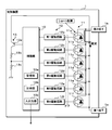
- FIG. 1 is a circuit block diagram illustrating a configuration example of a vehicle current control system according to the first embodiment.
- the vehicle current control system according to the first embodiment includes a vehicle control device 1, a starter generator 2, an in-vehicle battery 3, and a load 4.
- the control device 1 includes a control unit 10, a switching circuit 11, a drive unit 12, and a voltage detection unit 13.
- the first terminal 1a is connected to one end of the switching circuit 11, and the second terminal 1b is connected to the other end of the switching circuit 11.
- the first terminal 1a is connected to one end of the starter generator 2 and the other end of the starter generator 2 is grounded.
- the starter generator 2 has a power generating function in addition to a starter function for starting the vehicle engine, and includes a motor 21 for starting the engine and a capacitor 22.
- One end of the capacitor 22 is connected to the first terminal 1a, and the other end of the capacitor 22 is grounded.
- the positive terminal of the vehicle-mounted battery 3 is connected to the second terminal 1b, and the negative electrode of the vehicle-mounted battery 3 is grounded.
- one end of the load 4 is connected to the second terminal 1b, and the other end of the load 4 is grounded.
- the load 4 is an in-vehicle device such as an interior light, an air conditioner, a car navigation device, or the like.
- the starter generator 2 is connected to the vehicle-mounted battery 3 and the load 4 via the control device 1.
- the control device 1 opens and closes between the starter generator 2 and the vehicle-mounted battery 3.
- the starter generator 2 including the capacitor 22 and the vehicle battery 3 are connected.
- the vehicle-mounted battery 3 and the capacitor 22 are charged by the power generation of the starter generator 2.
- the capacitor 22 is charged by the on-vehicle battery 3 when the capacitor 22 and the on-vehicle battery 3 are connected.
- the control device 1 opens the circuit and disconnects the starter generator 2 and the vehicle-mounted battery 3.
- the motor 21 When the engine is started in this state, the motor 21 is driven by the starter battery (not shown) connected to the starter generator 2, and the engine is started. Although a large amount of electric power is required to drive the motor 21, the starter generator 2 and the vehicle-mounted battery 3 and the load 4 are disconnected, so it is possible to avoid problems such as a drop in the voltage on the load 4 side.
- the control device 1 closes the circuit, and the starter generator 2 and the vehicle-mounted battery 3 are connected.
- FIG. 2 is a block diagram showing a configuration example of the control device 1.
- the switching circuit 11 has first to sixth semiconductor switches 11a, 11b, 11c, 11d, 11e, 11f connected in parallel. .., 11f are preferably MOSFETs (Metal-Oxide-Semiconductor Field-Effect Transistors), IGBTs (Insulated Gate Bipolar Transistors), and the like.
- MOSFETs Metal-Oxide-Semiconductor Field-Effect Transistors
- IGBTs Insulated Gate Bipolar Transistors
- description will be made assuming that the first to sixth semiconductor switches 11a,..., 11f are N-channel MOSFETs.
- the drains of the first to sixth semiconductor switches 11a,..., 11f are connected to the second terminal 1b, and the sources are connected to the first terminal 1a.
- the switching circuit 11 in which six semiconductor switches are connected in parallel is described, but the number of semiconductor switches is not particularly limited to six.
- the driving unit 12 includes first to sixth driving circuits 12a, 12b, 12c, 12d, 12e, and 12f for turning on/off the first to sixth semiconductor switches 11a,..., 11f, the operation of which is controlled by the control unit 10. Controlled.
- the output terminals of the first to sixth drive circuits 12a,..., 12f are connected to the gates of the first to sixth semiconductor switches 11a,..., 11f, and the first to sixth drive circuits 12a,. By applying the drive voltage to the gate, the first to sixth semiconductor switches 11a,..., 11f are turned on and off.
- the first drive circuit 12a includes, for example, a first transistor and a second transistor connected in series, and the gate of the first semiconductor switch 11a is connected to the connection point of the first transistor and the second transistor.
- the control unit 10 is a computer having a CPU, a storage unit 10a, a clock unit 10b, an input/output unit 10c, and the like, which are not shown.
- the storage unit 10a stores information for determining whether or not there is a failure in the first to sixth semiconductor switches 11a,..., 11f. Details of the information will be described later.
- the storage unit 10a also stores the failure diagnosis results of the first to sixth semiconductor switches 11a,..., 11f.
- the input/output unit 10c externally outputs a signal or data indicating a failure of the first to sixth semiconductor switches 11a,..., 11f or the presence/absence of a failure.
- the voltage detection unit 13 includes a transistor switch 13a and voltage dividing resistors 13b and 13c connected in series.
- the control unit 10 can detect the voltage of the first terminal 1a, that is, the first terminal 1a of the switching circuit 11, by turning on the transistor switch 13a and acquiring the divided voltage.
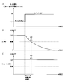
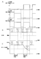
- FIG. 3 is a timing chart showing the failure determination method according to the first embodiment.
- the horizontal axis represents time.
- the vertical axis in FIG. 3A indicates the on/off state of the first to sixth semiconductor switches 11a,..., 11f, and the vertical axis in FIG. 3B indicates the voltage VBATT of the first terminal 1a detected by the voltage detection unit 13. ing.
- the voltage V0 indicates a predetermined voltage of the vehicle-mounted battery 3.
- the predetermined voltage is a rated voltage, which is a constant that does not change depending on the state of the vehicle-mounted battery 3.
- the voltage of the first terminal 1a is the predetermined voltage V0 of the vehicle-mounted battery 3 and the voltage of the capacitor 22 is also the voltage V0.
- the capacitor 22 is discharged (see the white arrow in FIG. 1), and the voltage VBATT at the first terminal 1a exponentially decreases. ..
- the predetermined time is shorter than the time required to complete the discharge of the capacitor 22 charged by the vehicle-mounted battery 3.
- the threshold voltage is the difference between the voltage V0 and the voltage VBATT of the first terminal 1a detected when the fully charged capacitor 22 starts discharging and a predetermined diagnosis waiting time (predetermined time) elapses.
- a value obtained by subtracting the threshold voltage from the voltage V0 is called a threshold.
- the storage unit 10a of the control unit 10 stores the threshold voltage and the diagnostic waiting time.
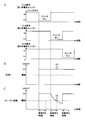
- FIG. 4 is an explanatory diagram showing a method of diagnosing a short circuit failure
- FIG. 5 is a timing chart showing a method of diagnosing a short circuit failure.
- the horizontal axis represents time.
- the vertical axis in FIG. 5A represents the voltage level of the input signal output from the control unit 10 to the first to sixth drive circuits 12a,..., 12f
- the vertical axis in FIGS. 5B and 5C represents the first terminal 1a.
- the voltage VBATT is shown.
- 5B shows changes in the voltage VBATT when the first to sixth semiconductor switches 11a,..., 11f are normal
- FIG. 5C shows a short-circuit failure in any of the first to sixth semiconductor switches 11a,.
- the change in the voltage VBATT during the operation is shown.
- the control unit 10 controls all the first to sixth semiconductor switches 11a,..., 11f from on to off.
- the switching circuit 11 is turned off. Therefore, the capacitor 22 and the vehicle-mounted battery 3 are disconnected, the capacitor 22 is discharged, and the voltage of the capacitor 22 decreases as shown in FIG. 5B.
- control unit 10 uses the voltage V2 of the first terminal 1a when a predetermined diagnostic waiting time has elapsed after controlling the first to sixth semiconductor switches 11a,..., 11f from ON to OFF, It is possible to determine whether or not there is a short circuit failure in the first to sixth semiconductor switches 11a,..., 11f.
- FIG. 6 is an explanatory diagram showing a method of diagnosing an open fault
- FIG. 7 is a timing chart showing a method of diagnosing an open fault.
- the vertical axis in FIG. 7A represents the voltage level of the input signal output from the control unit 10 to the first to third drive circuits 12c
- the vertical axis in FIGS. 7B and 7C represents the voltage VBATT of the first terminal 1a.
- 7B shows a change in the voltage VBATT when the first to third semiconductor switches 11a, 11b, 11c are normal
- FIG. 7C shows a change in the voltage VBATT when the second semiconductor switch 11b has an open failure. Shows.
- the control unit 10 controls any one of the first to sixth semiconductor switches 11a,..., 11f to be turned on. For example, as shown in FIG. 7A, only the first semiconductor switch 11a is controlled to be turned on. The other second to sixth semiconductor switches 11b, 11c, 11d, 11e and 11f are off.
- the first semiconductor switch 11a is normally turned on, the capacitor 22 and the vehicle-mounted battery 3 are connected and the capacitor 22 is charged. The charging of the capacitor 22 is completed in a short time, and the battery of the capacitor 22 becomes the voltage of the vehicle-mounted battery 3. Therefore, as shown in FIG. 7B, the voltage of the first terminal 1a becomes the voltage V0.
- the second semiconductor switch 11b is controlled to be turned on.
- the switching circuit 11 does not turn on. Therefore, the capacitor 22 and the vehicle-mounted battery 3 are disconnected, the capacitor 22 is discharged, and the voltage of the capacitor 22 decreases as shown in FIG. 7C.
- the control unit 10 uses the voltage V2 of the first terminal 1a at the time when a predetermined diagnostic waiting time has elapsed after controlling the second semiconductor switch 11b to be turned on, and short-circuits the second semiconductor switch 11b. The presence or absence of can be determined. Similarly, the control unit 10 uses the voltage V2 of the first terminal 1a when a predetermined diagnostic waiting time has elapsed after controlling one of the first to sixth semiconductor switches 11a,..., 11f to be turned on. , 1 to 6 semiconductor switches 11a,...
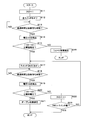
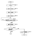
- FIG. 8 is a flowchart showing the processing procedure of the failure determination method according to the first embodiment.
- the control unit 10 substitutes 1 into the variable IND (step S11).
- the variable IND indicates one of the first to sixth semiconductor switches 11a,..., 11f by a numerical value.
- control unit 10 controls the first to sixth semiconductor switches 11a,..., 11f from on to off (step S12).
- the control unit 10 determines whether or not the elapsed time after controlling the first to sixth semiconductor switches 11a,..., 11f from on to off is equal to or longer than a predetermined diagnostic waiting time (step S13). When it is determined that the elapsed time is not longer than the diagnosis waiting time (step S13: NO), the control unit 10 returns the process to step S13 and continues the diagnosis process.
- the control unit 10 causes the voltage detection unit 13 to detect the voltage V2 (step S14).
- the voltage V2 indicates the voltage VBATT of the first terminal 1a detected when the elapsed time for waiting for diagnosis has elapsed as shown in FIG.
- the control unit 10 determines whether the absolute value of the difference between the voltage V0 of the vehicle-mounted battery 3 and the voltage V2 detected in step S14 is equal to or higher than the threshold voltage (step S15). When it is determined that the absolute value is less than the threshold voltage (step S15: NO), the control unit 10 definitely diagnoses that the first to sixth semiconductor switches 11a,..., 11f have a short circuit failure (step S16). ), processing is completed. When it is determined that the absolute value is equal to or higher than the threshold voltage (step S15: YES), the control unit 10 controls one of the first to sixth semiconductor switches 11a,..., 11f indicated by the variable IND from off to on.
- Step S17 it is determined whether or not the elapsed time after the ON control is longer than or equal to a predetermined diagnostic waiting time (step S18).
- a predetermined diagnostic waiting time step S18: NO
- the control unit 10 returns the process to step S18 and continues the diagnosis process.
- step S18 When it is determined that the elapsed time is equal to or longer than the diagnostic waiting time (step S18: YES), the control unit 10 causes the voltage detection unit 13 to detect the voltage V2 (step S19).
- control unit 10 determines whether the absolute value of the difference between the voltage V0 of the vehicle-mounted battery 3 and the voltage V2 detected in step S19 is equal to or higher than the threshold voltage (step S20). When it is determined that the absolute value is equal to or higher than the threshold voltage (step S20: YES), the control unit 10 determines that one of the first to sixth semiconductor switches 11a,..., 11f indicated by the variable IND has an open failure. Diagnosis is made (step S21), and the process ends.
- step S20 When it is determined in step S20 that the absolute value is less than the threshold voltage (step S20: NO), the control unit 10 increments the variable IND by 1 (step S22). Then, the control unit 10 determines whether or not the variable IND is larger than the number of the first to sixth semiconductor switches 11a,..., 11f (step S23). When it is determined that the variable IND is equal to or less than the number of switches (step S23: NO), the control unit 10 returns the process to step S17 and diagnoses the open failure of the other first to sixth semiconductor switches 11a,..., 11f. continue. When it is determined that the variable IND is larger than the number of switches (step S23: YES), the control unit 10 ends the process.
- the control unit 10 may store the failure determination result shown in FIG. 8 in the storage unit 10a. Further, the control unit 10 may be configured to externally output the failure determination result via the input/output unit 10c. Further, in the first embodiment, an example in which the absolute value of the difference between the voltage V0 of the vehicle-mounted battery 3 and the voltage V2 detected in step S14 or step S19 is greater than or equal to the threshold voltage has been described. It may be configured to determine whether or not the voltage V2 detected in step S14 is less than or equal to the threshold value (see FIG. 3).
- the control unit 10 that executes the process of step S15 causes a short-circuit failure in the first to sixth semiconductor switches 11a,..., 11f. If it is determined that the voltage V2 is equal to or lower than a predetermined threshold value, it is possible to determine that the first to sixth semiconductor switches 11a,..., 11f are not short-circuited.
- the control unit 10 that executes the process of step S20 opens one of the first to sixth semiconductor switches 11a,..., 11f indicated by the variable IND.
- the voltage V2 is higher than the threshold value, it may be determined that one of the first to sixth semiconductor switches 11a,..., 11f indicated by the variable IND does not have an open failure. ..
- the control device 1 and the failure determination method according to the first embodiment configured as described above when the capacitor 22 is connected to the circuit to be controlled to be switched, it is not necessary to wait until the capacitor 22 is completely discharged. Also, it is possible to quickly determine whether or not the switching circuit 11 has a failure.
- the switching circuit 11 can open and close a circuit through which a large current that cannot be controlled by one semiconductor switch flows. it can.
- FIG. 9 is a timing chart showing a method of diagnosing a short circuit failure according to the second embodiment.
- 9A to 9C are views similar to FIGS. 5A to 5C.
- the control unit 10 When determining the presence or absence of a short circuit failure, the control unit 10 first detects the voltage V1 of the first terminal 1a. That is, the current voltage of the vehicle-mounted battery 3 is detected.
- the control device 1 according to the second embodiment determines whether or not there is a failure in the switching circuit 11 by using not the rated voltage V0 of the vehicle-mounted battery 3 but the current voltage V1 of the vehicle-mounted battery 3.
- the control unit 10 controls all the first to sixth semiconductor switches 11a,..., 11f from on to off.
- the capacitor 22 and the vehicle-mounted battery 3 are disconnected, the capacitor 22 is discharged, and the voltage of the capacitor 22 is changed as shown in FIG. 9B. That is, the voltage VBATT at the first terminal 1a decreases.
- the voltage of the capacitor 22 that is, the voltage VBATT of the first terminal 1a does not decrease as shown in FIG. 9C.
- the control unit 10 controls the voltage V1 of the first terminal 1a before switching control, and controls the first to sixth semiconductor switches 11a,..., 11f from ON to OFF when a predetermined diagnostic waiting time elapses. Whether or not there is a short circuit failure in the first to sixth semiconductor switches 11a,..., 11f can be determined using the magnitude of the difference from the voltage V2 at the 1-terminal 1a.
- FIG. 10 is a timing chart showing a method of diagnosing an open failure according to the second embodiment.
- 10A, 10B, and 10C are views similar to FIG. 7.
- the presence or absence of the open failure is determined in the same manner as in the first embodiment, but the voltage V1 of the first terminal 1a immediately before turning on the first to sixth semiconductor switches 11a,..., 11f is detected. The points are different.
- the control unit 10 Immediately before turning on each of the first to sixth semiconductor switches 11a,..., 11f one by one, the control unit 10 temporarily sets all the first to sixth semiconductor switches 11a,..., 11f as shown in FIG. 10A. Is turned on (the input signal is at the low level Lo), and the voltage V1 of the first terminal 1a is detected.
- the control unit 10 controls the voltage V1 of the first terminal 1a before the switching control and one of the first to sixth semiconductor switches 11a,... Whether or not there is an open failure in each of the first to sixth semiconductor switches 11a,..., 11f can be determined using the magnitude of the difference from the voltage V2 at the first terminal 1a.
- 11 and 12 are flowcharts showing the processing procedure of the failure determination method according to the second embodiment.
- the control unit 10 substitutes 1 into the variable IND (step S211). Then, the controller 10 turns on the first to sixth semiconductor switches 11a,..., 11f (step S212), and causes the voltage detector 13 to detect the voltage V1 of the first terminal 1a (step S213). Next, the control unit 10 detects the voltage of the first terminal 1a after the elapse of a predetermined diagnostic waiting time by executing the same processing as Steps S12 to 14 of the first embodiment in Steps S214 to S216.
- the control unit 10 determines whether the absolute value of the difference between the voltage V1 detected in step S213 and the voltage V2 detected in step S216 is equal to or more than the threshold voltage (step S217). When it is determined that the absolute value is less than the threshold voltage (step S217: NO), the control unit 10 definitely diagnoses that the first to sixth semiconductor switches 11a,..., 11f have a short circuit failure (step S218). ), processing is completed. When it is determined that the absolute value is equal to or higher than the threshold voltage (step S217: YES), the control unit 10 turns on the first to sixth semiconductor switches 11a,..., 11f (step S219), and causes the voltage detection unit 13 to operate. The voltage V1 of the first terminal 1a is detected (step S220).
- control unit 10 controls the switches other than one of the first to sixth semiconductor switches 11a,..., 11f indicated by the variable IND to be turned off, and the elapsed time after performing the switching control waits for a predetermined diagnosis. It is determined whether it is time or more (step S222). When it is determined that the elapsed time is not longer than the diagnosis waiting time (step S222: NO), the control unit 10 returns the process to step S222 and continues the diagnosis process.
- control unit 10 When it is determined that the elapsed time is equal to or longer than the diagnostic waiting time (step S222: YES), the control unit 10 causes the voltage detection unit 13 to detect the voltage V2 (step S223).
- the control unit 10 determines whether the absolute value of the difference between the voltage V1 detected in step S220 and the voltage V2 detected in step S223 is equal to or more than the threshold voltage (step S224).
- step S224 YES
- processing is completed.
- the processing of steps S226 and S227 when the absolute value is less than the threshold voltage is the same as the processing of steps S22 and S23 of the first embodiment.
- control device 1 and the failure determination method according to the second embodiment configured as described above have the same effects as those of the first embodiment, and further, the failure of the switching circuit 11 can be detected without depending on the voltage level of the vehicle-mounted battery 3. The presence or absence can be determined.
- FIG. 13 is a flowchart showing the processing procedure of the failure determination method according to the third embodiment.
- the control unit 10 substitutes 1 into the variable IND (step S310). Then, the controller 10 turns on the first to sixth semiconductor switches 11a,..., 11f (step S311), and causes the voltage detector 13 to detect the voltage V1 of the first terminal 1a (step S312). Next, the control unit 10 determines the diagnostic waiting time based on the detected voltage V1 (step S313). For example, the control unit 10 determines the threshold voltage so that the diagnosis waiting time becomes shorter as the voltage V1 is higher. Then, the control unit 10 controls the first to sixth semiconductor switches 11a,..., 11f from on to off (step S314). The subsequent processing is the same as steps S13 to S23 of the first embodiment.
- the presence or absence of the failure of the switching circuit 11 can be determined more quickly by using the diagnostic waiting time according to the voltage level of the vehicle-mounted battery 3. can do.
- the threshold voltage may be changed based on the voltage V1 detected in step S312, or both the threshold voltage and the diagnosis waiting time may be changed. May be.
- Control device 1a 1st terminal 1b 2nd terminal 2 Starter generator 3 Vehicle-mounted battery 4 Load 10 Control part 10a Storage part 10b Timing part 10c Input/output part 11 Switching circuit 11a 1st semiconductor switch 11b 2nd semiconductor switch 11c 3rd semiconductor Switch 11d Fourth semiconductor switch 11e Fifth semiconductor switch 11f Sixth semiconductor switch 12 Driving unit 12a First driving circuit 12b Second driving circuit 12c Third driving circuit 12d Fourth driving circuit 12e Fifth driving circuit 12f Sixth driving circuit 13 Voltage detector 13b, 13c Voltage dividing resistor 21 Motor 22 Capacitor
Abstract
A control device of a vehicle is provided with a switching circuit, and by controlling the turning on and off of the switching circuit, opens and closes a connection between a starter having a capacitor, connected to one end portion of the switching circuit, and a vehicle-mounted battery connected to another end portion of the switching circuit. The control device is provided with: a voltage detecting unit for detecting the voltage of said one end portion; and a control unit which controls the switching circuit from on to off, and determines the presence or absence of a failure in the switching circuit on the basis of the voltage detected by the voltage detecting unit when a prescribed length of time has elapsed after the switching circuit has been controlled from on to off.
Description
本開示は制御装置及び故障判定方法に関する。
本出願は、2018年12月11日出願の日本出願第2018-231892号に基づく優先権を主張し、前記日本出願に記載された全ての記載内容を援用するものである。 The present disclosure relates to a control device and a failure determination method.
This application claims the priority based on Japanese application No. 2018-231892 filed on December 11, 2018, and incorporates all the contents described in the Japanese application.
特許文献1には、負荷に供給する大電流を制御するために複数の半導体スイッチを並列してなるスイッチング回路において、各半導体スイッチに故障診断ユニットを設けてなる車両用制御装置が開示されている。故障診断ユニットは半導体スイッチに入力されるオンオフ制御信号と、半導体スイッチの出力レベルとの整合性を判断することによって、半導体スイッチの動作不良の有無を診断する。
Patent Document 1 discloses a vehicle control device in which a failure diagnosis unit is provided in each semiconductor switch in a switching circuit in which a plurality of semiconductor switches are arranged in parallel to control a large current supplied to a load. .. The failure diagnosis unit diagnoses whether or not there is a malfunction in the semiconductor switch by determining the consistency between the ON/OFF control signal input to the semiconductor switch and the output level of the semiconductor switch.
本態様に係る制御装置は、スイッチング回路を備え、該スイッチング回路のオンオフを制御することによって、前記スイッチング回路の一端部に接続されるコンデンサを有するスタータと、前記スイッチング回路の他端部に接続される車載バッテリとの間を開閉する車両用の制御装置であって、前記一端部の電圧を検出する電圧検出部と、前記スイッチング回路をオンからオフに制御し、前記スイッチング回路をオンからオフに制御してから所定時間が経過したときに前記電圧検出部によって検出された電圧に基づいて、前記スイッチング回路の故障の有無を判定する制御部とを備える。
A control device according to this aspect includes a switching circuit, and a starter having a capacitor connected to one end of the switching circuit by controlling on/off of the switching circuit, and a starter having the other end of the switching circuit. A control device for a vehicle that opens and closes between an on-vehicle battery and a voltage detection unit that detects a voltage at the one end, and controls the switching circuit from on to off, thereby switching the switching circuit from on to off. And a control unit that determines whether or not there is a failure in the switching circuit based on the voltage detected by the voltage detection unit when a predetermined time has elapsed after the control.
本態様に係る故障判定方法は、スイッチング回路を備え、該スイッチング回路のオンオフを制御することによって、前記スイッチング回路の一端部に接続されるコンデンサを有するスタータと、前記スイッチング回路の他端部に接続される車載バッテリとの間を開閉する車両用の制御装置の故障を判定する故障判定方法であって、前記スイッチング回路をオンからオフに制御するステップと、前記スイッチング回路をオンからオフに制御してから所定時間が経過したときに前記一端部の電圧を検出するステップと、検出された電圧に基づいて、前記スイッチング回路の故障の有無を判定するステップとを備える。
A failure determination method according to this aspect includes a switching circuit, and a starter having a capacitor connected to one end of the switching circuit by controlling ON/OFF of the switching circuit, and a starter having the other end of the switching circuit. A failure determination method for determining a failure of a vehicle control device that opens and closes between an on-vehicle battery and a step of controlling the switching circuit from on to off, and controlling the switching circuit from on to off. And a step of detecting the voltage at the one end when a predetermined time has elapsed, and a step of determining whether or not there is a failure in the switching circuit based on the detected voltage.
[本開示が解決しようとする課題]
特許文献1に係る車両用制御装置においては、開閉制御対象の回路にコンデンサが接続されている場合、そのコンデンサの容量が大きいと、コンデンサの放電に時間を要し、スイッチング回路の故障診断に時間を要するという技術的問題がある。
例えば、コンデンサを有するスタータと、車載バッテリとの間をスイッチング回路によって開閉するように構成した場合、オン状態にあるスイッチング回路がオフになってもコンデンサが放電され、電圧が低下するまでに時間がかかり、結果としてスイッチング回路が正常に動作しているか否かの診断に時間を要することになる。 [Problems to be solved by the present disclosure]
In the vehicle control device according toPatent Document 1, when a capacitor is connected to the circuit to be controlled to be opened and closed, if the capacitance of the capacitor is large, it takes time to discharge the capacitor, and it takes time to diagnose the failure of the switching circuit. There is a technical problem that requires
For example, when a switching circuit is used to open and close between a starter having a capacitor and an in-vehicle battery, even if the switching circuit in the on state is turned off, the capacitor is discharged and it takes time until the voltage drops. As a result, it takes time to diagnose whether the switching circuit is operating normally.
特許文献1に係る車両用制御装置においては、開閉制御対象の回路にコンデンサが接続されている場合、そのコンデンサの容量が大きいと、コンデンサの放電に時間を要し、スイッチング回路の故障診断に時間を要するという技術的問題がある。
例えば、コンデンサを有するスタータと、車載バッテリとの間をスイッチング回路によって開閉するように構成した場合、オン状態にあるスイッチング回路がオフになってもコンデンサが放電され、電圧が低下するまでに時間がかかり、結果としてスイッチング回路が正常に動作しているか否かの診断に時間を要することになる。 [Problems to be solved by the present disclosure]
In the vehicle control device according to
For example, when a switching circuit is used to open and close between a starter having a capacitor and an in-vehicle battery, even if the switching circuit in the on state is turned off, the capacitor is discharged and it takes time until the voltage drops. As a result, it takes time to diagnose whether the switching circuit is operating normally.
本開示の目的は、開閉制御対象の回路にコンデンサが接続されている場合において、コンデンサが完全に放電するまで待機しなくても、スイッチング回路の故障の有無を速やかに判定することができる制御装置及び故障判定方法を提供することにある。
An object of the present disclosure is to provide a control device capable of promptly determining the presence/absence of a failure in a switching circuit when a capacitor is connected to a circuit to be controlled to be switched, without waiting for the capacitor to be completely discharged. And to provide a failure determination method.
[本開示の効果]
本開示によれば、開閉制御対象の回路にコンデンサが接続されている場合において、コンデンサが完全に放電するまで待機しなくても、スイッチング回路の故障の有無を速やかに判定することができる制御装置及び故障判定方法を提供することができる。 [Effect of the present disclosure]
According to the present disclosure, when a capacitor is connected to a circuit to be controlled to open and close, it is possible to quickly determine whether or not there is a failure in the switching circuit without waiting for the capacitor to be completely discharged. And a failure determination method can be provided.
[本開示の実施形態の説明]
最初に本開示の実施態様を列記して説明する。また、以下に記載する実施形態の少なくとも一部を任意に組み合わせてもよい。 [Description of Embodiments of the Present Disclosure]
First, embodiments of the present disclosure will be listed and described. Further, at least a part of the embodiments described below may be arbitrarily combined.
最初に本開示の実施態様を列記して説明する。また、以下に記載する実施形態の少なくとも一部を任意に組み合わせてもよい。 [Description of Embodiments of the Present Disclosure]
First, embodiments of the present disclosure will be listed and described. Further, at least a part of the embodiments described below may be arbitrarily combined.
(1)本態様に係る制御装置は、スイッチング回路を備え、該スイッチング回路のオンオフを制御することによって、前記スイッチング回路の一端部に接続されるコンデンサを有するスタータと、前記スイッチング回路の他端部に接続される車載バッテリとの間を開閉する車両用の制御装置であって、前記一端部の電圧を検出する電圧検出部と、前記スイッチング回路をオンからオフに制御し、前記スイッチング回路をオンからオフに制御してから所定時間が経過したときに前記電圧検出部によって検出された電圧に基づいて、前記スイッチング回路の故障の有無を判定する制御部とを備える。
(1) A control device according to the present aspect includes a switching circuit, a starter having a capacitor connected to one end of the switching circuit by controlling ON/OFF of the switching circuit, and the other end of the switching circuit. A control device for a vehicle that opens and closes between a vehicle-mounted battery that is connected to, a voltage detection unit that detects a voltage at the one end, and a switching circuit that controls the switching circuit from on to off, thereby turning on the switching circuit. And a control unit that determines whether or not there is a failure in the switching circuit based on the voltage detected by the voltage detection unit when a predetermined time has elapsed after the control from OFF to OFF.
本態様にあっては、制御部は、短い時間でスイッチング回路の故障の有無を判定することができる。例えば、所定時間を、前記車載バッテリによって充電された前記コンデンサの放電を完了させるために要する時間よりも短い時間に設定することによって、制御部は、車載バッテリによって充電されたコンデンサを完全に放電させるために要する時間よりも短い時間でスイッチング回路の故障の有無を判定することができる。
スイッチング回路の故障の有無を判断する際、制御部は、スイッチング回路をオンからオフに制御する。スイッチング回路がオンのとき、コンデンサと車載バッテリとが接続され、コンデンサは充電された状態になっている。上記スイッチング回路の制御により、スイッチング回路が正常にオフになった場合、コンデンサは車載バッテリから切断され、コンデンサは放電を開始し、スイッチング回路の一端部の電圧が低下する。
コンデンサが放電し、スイッチング回路の一端部の電圧が基準電位に低下した場合、スイッチング回路は正常にオンからオフに制御されたと判断できる。しかし、コンデンサの容量が大きい程、コンデンサの放電に時間を要し、スイッチング回路の故障の有無の判定にも時間を要することになる。
そこで、本態様にあっては、制御部は、スイッチング回路をオンからオフに制御してから所定時間が経過したときのスイッチング回路の一端部の電圧に基づいて、当該スイッチング回路の故障の有無が判定する。所定時間は、車載バッテリによって充電されたコンデンサを完全に放電させるために要する時間よりも短い。当該閾値は、例えばスイッチング回路がオンからオフに制御されてから所定時間が経過したときのコンデンサの電圧であり、スイッチング回路が正常のオンからオフになったかどうかを判定するための数値である。
従って、制御部は、所定時間が経過する前、つまりコンデンサの放電が完了する前にスイッチング回路の故障の有無を判定することができる。 In this aspect, the control unit can determine whether or not there is a failure in the switching circuit in a short time. For example, by setting the predetermined time to a time shorter than the time required to complete the discharge of the capacitor charged by the vehicle-mounted battery, the control unit completely discharges the capacitor charged by the vehicle-mounted battery. Therefore, it is possible to determine whether or not there is a failure in the switching circuit in a time shorter than the time required for this.
When determining whether or not there is a failure in the switching circuit, the control unit controls the switching circuit from on to off. When the switching circuit is on, the capacitor and the vehicle-mounted battery are connected and the capacitor is in a charged state. When the switching circuit is normally turned off by the control of the switching circuit, the capacitor is disconnected from the vehicle-mounted battery, the capacitor starts discharging, and the voltage at one end of the switching circuit decreases.
When the capacitor is discharged and the voltage at the one end of the switching circuit drops to the reference potential, it can be determined that the switching circuit is normally controlled from ON to OFF. However, the larger the capacity of the capacitor, the longer it takes to discharge the capacitor, and the longer it takes to determine whether or not there is a failure in the switching circuit.
Therefore, in this aspect, the control unit determines whether or not there is a failure in the switching circuit based on the voltage at the one end of the switching circuit when a predetermined time has elapsed after controlling the switching circuit from ON to OFF. judge. The predetermined time is shorter than the time required to completely discharge the capacitor charged by the vehicle-mounted battery. The threshold value is, for example, the voltage of the capacitor when a predetermined time has elapsed after the switching circuit was controlled from ON to OFF, and is a numerical value for determining whether the switching circuit normally turned from ON to OFF.
Therefore, the control unit can determine whether or not there is a failure in the switching circuit before a predetermined time elapses, that is, before the discharge of the capacitor is completed.
(2)前記スイッチング回路は並列接続された複数の半導体スイッチを有し、前記制御部は前記複数の半導体スイッチを同時的にオンオフさせることによって、前記スタータと前記車載バッテリとの間を開閉するようにしてあり、前記制御部は、前記スイッチング回路がオンの状態で、前記複数の半導体スイッチの全部又は一部をオンからオフに制御し、前記複数の半導体スイッチの全部又は一部をオンからオフに制御してから前記所定時間が経過したときに前記電圧検出部によって検出された電圧に基づいて、前記複数の半導体スイッチの故障の有無を判定する構成が好ましい。
(2) The switching circuit has a plurality of semiconductor switches connected in parallel, and the control unit opens and closes the starter and the vehicle-mounted battery by simultaneously turning on and off the plurality of semiconductor switches. The control unit controls all or part of the plurality of semiconductor switches from on to off while the switching circuit is on, and turns all or part of the plurality of semiconductor switches from on to off. It is preferable that the presence/absence of a failure of the plurality of semiconductor switches is determined based on the voltage detected by the voltage detection unit when the predetermined time has elapsed after the control.
本態様にあっては、スイッチング回路は並列接続された複数の半導体スイッチを有する。このため、制御装置は、一つの半導体スイッチでは制御できない大電流が流れる回路を開閉することができる。制御部は、かかる複数の半導体スイッチの故障の有無を判定することができる。
In this aspect, the switching circuit has a plurality of semiconductor switches connected in parallel. Therefore, the control device can open and close a circuit through which a large current that cannot be controlled by one semiconductor switch flows. The control unit can determine whether or not there is a failure in the plurality of semiconductor switches.
(3)前記制御部は、前記スイッチング回路がオンの状態で、前記複数の半導体スイッチをオフに制御し、前記複数の半導体スイッチをオフに制御してから前記所定時間が経過したときに前記電圧検出部によって検出された電圧が、所定の閾値より大きい場合、前記半導体スイッチがショートしたショート故障であると判定する構成が好ましい。
(3) The control unit controls the plurality of semiconductor switches to be off while the switching circuit is on, and controls the plurality of semiconductor switches to be off when the predetermined time has elapsed. When the voltage detected by the detection unit is larger than a predetermined threshold value, it is preferable to determine that the semiconductor switch is short-circuited and has a short circuit failure.
本態様にあっては、半導体スイッチのショート故障の有無を判定することができる。
In this aspect, it is possible to determine whether there is a short circuit failure in the semiconductor switch.
(4)前記制御部は、前記スイッチング回路がオンの状態で前記電圧検出部にて検出された電圧と、前記スイッチング回路がオンの状態で、前記複数の半導体スイッチをオフに制御し、前記複数の半導体スイッチをオフに制御してから前記所定時間が経過したときに前記電圧検出部によって検出された電圧との差分が、所定の閾値電圧未満である場合、前記半導体スイッチがショートしたショート故障であると判定する構成が好ましい。
(4) The control unit controls the voltage detected by the voltage detection unit when the switching circuit is on and the semiconductor switches to be off when the switching circuit is on. When the difference from the voltage detected by the voltage detection unit when the predetermined time has elapsed after controlling the semiconductor switch to be OFF is less than a predetermined threshold voltage, a short-circuit failure in which the semiconductor switch is short-circuited A configuration that determines that there is is preferable.
本態様にあっては、車載バッテリの電圧レベルに依存ずることなく、半導体スイッチのショート故障の有無を判定することができる。
In this aspect, it is possible to determine whether or not there is a short circuit failure in the semiconductor switch without depending on the voltage level of the vehicle-mounted battery.
(5)前記制御部は、一の前記半導体スイッチをオン、他の複数の前記半導体スイッチをオフに制御し、前記一の半導体スイッチをオンに制御してから前記所定時間が経過したときに前記電圧検出部によって検出された電圧が、所定の閾値未満である場合、前記一の半導体スイッチがオンにならないオープン故障であると判定する構成が好ましい。
(5) The control unit controls one of the semiconductor switches to be turned on and another of the plurality of semiconductor switches to be turned off, and the control unit controls the one semiconductor switch to be turned on when the predetermined time has elapsed. When the voltage detected by the voltage detection unit is less than a predetermined threshold value, it is preferable to determine that the semiconductor switch is an open failure in which the one semiconductor switch is not turned on.
本態様にあっては、半導体スイッチのオープン故障の有無を判定することができる。
In this mode, it is possible to determine whether there is an open failure in the semiconductor switch.
(6)前記制御部は、前記スイッチング回路がオンの状態で前記電圧検出部にて検出された電圧と、一の前記半導体スイッチをオン、他の複数の前記半導体スイッチをオフに制御し、前記一の半導体スイッチをオンに制御してから前記所定時間が経過したときに前記電圧検出部によって検出された電圧との差分が、所定の閾値電圧以上である場合、前記一の半導体スイッチがオンにならないオープン故障であると判定する構成が好ましい。
(6) The control unit controls the voltage detected by the voltage detection unit when the switching circuit is on, one semiconductor switch to be turned on, and a plurality of other semiconductor switches to be turned off. When the difference from the voltage detected by the voltage detection unit when the predetermined time has elapsed after controlling one semiconductor switch to be turned on is equal to or higher than a predetermined threshold voltage, the one semiconductor switch is turned on. A configuration in which it is determined that the open failure does not occur is preferable.
本態様にあっては、車載バッテリの電圧レベルに依存ずることなく、半導体スイッチのオープン故障の有無を判定することができる。
In this aspect, it is possible to determine whether or not there is an open failure in the semiconductor switch without depending on the voltage level of the vehicle-mounted battery.
(7)前記制御部は、前記複数の半導体スイッチそれぞれを一つずつ選択的にオンに制御することによって、前記複数の半導体スイッチそれぞれのオープン故障を判定する構成が好ましい。
(7) It is preferable that the control unit determines the open failure of each of the plurality of semiconductor switches by selectively turning on each of the plurality of semiconductor switches.
本態様にあっては、複数の半導体スイッチそれぞれのオープン故障の有無を判定することができる。
In this aspect, it is possible to determine whether or not there is an open failure in each of the plurality of semiconductor switches.
(8)前記制御部は、前記スイッチング回路がオンの状態のときに前記電圧検出部にて検出された電圧に基づいて、前記所定時間の長さを設定する構成が好ましい。
(8) It is preferable that the control unit sets the length of the predetermined time based on the voltage detected by the voltage detection unit when the switching circuit is in the ON state.
本態様にあっては、車載バッテリの電圧レベルに応じた所定時間を用いて半導体スイッチの故障の有無を判定することができる。
In this aspect, it is possible to determine the presence/absence of a failure of the semiconductor switch by using a predetermined time period according to the voltage level of the vehicle-mounted battery.
(9)前記制御部は、前記スイッチング回路がオンの状態のときに前記電圧検出部にて検出された電圧が大きい程、前記所定時間の長さを短く設定する構成が好ましい。
(9) It is preferable that the control unit sets the length of the predetermined time to be shorter as the voltage detected by the voltage detection unit is higher when the switching circuit is in the ON state.
本態様にあっては、車載バッテリの電圧レベルに応じた所定時間を用いて、より速やかに半導体スイッチの故障の有無を判定することができる。
In this aspect, it is possible to more promptly determine the presence/absence of a semiconductor switch failure by using a predetermined time period according to the voltage level of the vehicle-mounted battery.
(10)本態様に係る故障判定方法は、スイッチング回路を備え、該スイッチング回路のオンオフを制御することによって、前記スイッチング回路の一端部に接続されるコンデンサを有するスタータと、前記スイッチング回路の他端部に接続される車載バッテリとの間を開閉する車両用の制御装置の故障を判定する故障判定方法であって、前記スイッチング回路をオンからオフに制御するステップと、前記スイッチング回路をオンからオフに制御してから所定時間が経過したときに前記一端部の電圧を検出するステップと、検出された電圧に基づいて、前記スイッチング回路の故障の有無を判定するステップとを備える。
(10) The failure determination method according to this aspect includes a starter having a switching circuit, the starter having a capacitor connected to one end of the switching circuit by controlling ON/OFF of the switching circuit, and the other end of the switching circuit. A failure determination method for determining a failure of a vehicle control device that opens and closes a vehicle-mounted battery connected to a vehicle part, the method comprising: controlling the switching circuit from ON to OFF; and turning the switching circuit from ON to OFF. The step of detecting the voltage of the one end when a predetermined time has elapsed after the control is performed, and the step of determining the presence or absence of a failure of the switching circuit based on the detected voltage.
本態様にあっては、態様(1)と同様、車載バッテリによって充電されたコンデンサを完全に放電させるために要する時間よりも短い時間でスイッチング回路の故障の有無を判定することができる。
In this mode, similarly to the mode (1), it is possible to determine the presence/absence of a failure in the switching circuit in a time shorter than the time required to completely discharge the capacitor charged by the vehicle-mounted battery.
(11)前記制御部は、前記スイッチング回路がオンの状態で前記電圧検出部にて検出された電圧、及び前記複数の半導体スイッチの全部又は一部をオンからオフに制御してから前記所定時間が経過したときに前記電圧検出部によって検出された電圧との差分と、所定の閾値電圧とを比較することによって、前記複数の半導体スイッチの故障の有無を判定する構成が好ましい。
(11) The control unit controls the voltage detected by the voltage detection unit in a state where the switching circuit is on, and all or a part of the plurality of semiconductor switches from on to off for the predetermined time. It is preferable that the presence/absence of a failure of the plurality of semiconductor switches be determined by comparing a difference between the voltage detected by the voltage detection unit and the predetermined threshold voltage when is passed.
本態様にあっては、車載バッテリの電圧レベルに依存ずることなく、半導体スイッチの故障の有無を判定することができる。
In this aspect, it is possible to determine whether or not the semiconductor switch has failed without depending on the voltage level of the vehicle-mounted battery.
[本開示の実施形態の詳細]
本開示の実施形態に係る制御装置及び故障判定方法の具体例を、以下に図面を参照しつつ説明する。なお、本発明はこれらの例示に限定されるものではなく、請求の範囲によって示され、請求の範囲と均等の意味及び範囲内でのすべての変更が含まれることが意図される。 [Details of the embodiment of the present disclosure]
Specific examples of the control device and the failure determination method according to the embodiment of the present disclosure will be described below with reference to the drawings. It should be noted that the present invention is not limited to these exemplifications, and is shown by the scope of the claims, and is intended to include meanings equivalent to the scope of the claims and all modifications within the scope.
以下、本開示をその実施形態を示す図面に基づいて具体的に説明する。
(実施形態1)
図1は、実施形態1に係る車両用電流制御システムの構成例を説明する回路ブロック図である。実施形態1に係る車両用電流制御システムは、車両用の制御装置1と、スタータ・ジェネレータ2と、車載バッテリ3と、負荷4とを備える。制御装置1は、制御部10と、スイッチング回路11と、駆動部12と、電圧検出部13とを備える。スイッチング回路11の一端部には第1端子1aが接続され、スイッチング回路11の他端部には第2端子1bが接続されている。第1端子1aはスタータ・ジェネレータ2の一端部に接続され、スタータ・ジェネレータ2の他端部は接地されている。スタータ・ジェネレータ2は、車両のエンジンを始動させるスタータ機能に加え、発電機能を有し、エンジン始動用のモータ21と、コンデンサ22とを備える。コンデンサ22の一端部は第1端子1aに接続され、コンデンサ22の他端は接地されている。第2端子1bには、車載バッテリ3の正極が接続され、車載バッテリ3の負極は接地されている。また、第2端子1bには、負荷4の一端部が接続され、負荷4の他端部は接地されている。負荷4は、車内灯、エアコンディショナー、カーナビゲーション装置等の車載機器である。 Hereinafter, the present disclosure will be specifically described based on the drawings showing the embodiments.
(Embodiment 1)
FIG. 1 is a circuit block diagram illustrating a configuration example of a vehicle current control system according to the first embodiment. The vehicle current control system according to the first embodiment includes avehicle control device 1, a starter generator 2, an in-vehicle battery 3, and a load 4. The control device 1 includes a control unit 10, a switching circuit 11, a drive unit 12, and a voltage detection unit 13. The first terminal 1a is connected to one end of the switching circuit 11, and the second terminal 1b is connected to the other end of the switching circuit 11. The first terminal 1a is connected to one end of the starter generator 2 and the other end of the starter generator 2 is grounded. The starter generator 2 has a power generating function in addition to a starter function for starting the vehicle engine, and includes a motor 21 for starting the engine and a capacitor 22. One end of the capacitor 22 is connected to the first terminal 1a, and the other end of the capacitor 22 is grounded. The positive terminal of the vehicle-mounted battery 3 is connected to the second terminal 1b, and the negative electrode of the vehicle-mounted battery 3 is grounded. Further, one end of the load 4 is connected to the second terminal 1b, and the other end of the load 4 is grounded. The load 4 is an in-vehicle device such as an interior light, an air conditioner, a car navigation device, or the like.
(実施形態1)
図1は、実施形態1に係る車両用電流制御システムの構成例を説明する回路ブロック図である。実施形態1に係る車両用電流制御システムは、車両用の制御装置1と、スタータ・ジェネレータ2と、車載バッテリ3と、負荷4とを備える。制御装置1は、制御部10と、スイッチング回路11と、駆動部12と、電圧検出部13とを備える。スイッチング回路11の一端部には第1端子1aが接続され、スイッチング回路11の他端部には第2端子1bが接続されている。第1端子1aはスタータ・ジェネレータ2の一端部に接続され、スタータ・ジェネレータ2の他端部は接地されている。スタータ・ジェネレータ2は、車両のエンジンを始動させるスタータ機能に加え、発電機能を有し、エンジン始動用のモータ21と、コンデンサ22とを備える。コンデンサ22の一端部は第1端子1aに接続され、コンデンサ22の他端は接地されている。第2端子1bには、車載バッテリ3の正極が接続され、車載バッテリ3の負極は接地されている。また、第2端子1bには、負荷4の一端部が接続され、負荷4の他端部は接地されている。負荷4は、車内灯、エアコンディショナー、カーナビゲーション装置等の車載機器である。 Hereinafter, the present disclosure will be specifically described based on the drawings showing the embodiments.
(Embodiment 1)
FIG. 1 is a circuit block diagram illustrating a configuration example of a vehicle current control system according to the first embodiment. The vehicle current control system according to the first embodiment includes a
このように構成された車両用電流制御システムでは、制御装置1を介してスタータ・ジェネレータ2が車載バッテリ3及び負荷4に接続される。制御装置1は、スタータ・ジェネレータ2と、車載バッテリ3との間を開閉する。
車両のエンジンが動作し、スタータ・ジェネレータ2が発電を行っている場合、コンデンサ22を含むスタータ・ジェネレータ2と、車載バッテリ3とが接続される。スタータ・ジェネレータ2の発電によって車載バッテリ3及びコンデンサ22は充電される。スタータ・ジェネレータ2が発電していないときも、コンデンサ22及び車載バッテリ3が接続されている状態にある場合、コンデンサ22は車載バッテリ3によって充電される。
車両のエンジンが停止した場合、制御装置1は回路を開き、スタータ・ジェネレータ2と、車載バッテリ3とを切断する。この状態でエンジンを始動する場合、スタータ・ジェネレータ2に接続された図示しないスタータ用バッテリによってモータ21が駆動し、エンジンが始動される。モータ21の駆動には大きな電力が必要であるが、スタータ・ジェネレータ2と、車載バッテリ3及び負荷4は切断されているため、負荷4側の電圧が低下する等の不具合を避けることができる。エンジンが始動すると、制御装置1は回路を閉じ、スタータ・ジェネレータ2と、車載バッテリ3とが接続される。 In the vehicle current control system configured as described above, thestarter generator 2 is connected to the vehicle-mounted battery 3 and the load 4 via the control device 1. The control device 1 opens and closes between the starter generator 2 and the vehicle-mounted battery 3.
When the engine of the vehicle is operating and thestarter generator 2 is generating electricity, the starter generator 2 including the capacitor 22 and the vehicle battery 3 are connected. The vehicle-mounted battery 3 and the capacitor 22 are charged by the power generation of the starter generator 2. Even when the starter generator 2 is not generating power, the capacitor 22 is charged by the on-vehicle battery 3 when the capacitor 22 and the on-vehicle battery 3 are connected.
When the engine of the vehicle is stopped, thecontrol device 1 opens the circuit and disconnects the starter generator 2 and the vehicle-mounted battery 3. When the engine is started in this state, the motor 21 is driven by the starter battery (not shown) connected to the starter generator 2, and the engine is started. Although a large amount of electric power is required to drive the motor 21, the starter generator 2 and the vehicle-mounted battery 3 and the load 4 are disconnected, so it is possible to avoid problems such as a drop in the voltage on the load 4 side. When the engine starts, the control device 1 closes the circuit, and the starter generator 2 and the vehicle-mounted battery 3 are connected.
車両のエンジンが動作し、スタータ・ジェネレータ2が発電を行っている場合、コンデンサ22を含むスタータ・ジェネレータ2と、車載バッテリ3とが接続される。スタータ・ジェネレータ2の発電によって車載バッテリ3及びコンデンサ22は充電される。スタータ・ジェネレータ2が発電していないときも、コンデンサ22及び車載バッテリ3が接続されている状態にある場合、コンデンサ22は車載バッテリ3によって充電される。
車両のエンジンが停止した場合、制御装置1は回路を開き、スタータ・ジェネレータ2と、車載バッテリ3とを切断する。この状態でエンジンを始動する場合、スタータ・ジェネレータ2に接続された図示しないスタータ用バッテリによってモータ21が駆動し、エンジンが始動される。モータ21の駆動には大きな電力が必要であるが、スタータ・ジェネレータ2と、車載バッテリ3及び負荷4は切断されているため、負荷4側の電圧が低下する等の不具合を避けることができる。エンジンが始動すると、制御装置1は回路を閉じ、スタータ・ジェネレータ2と、車載バッテリ3とが接続される。 In the vehicle current control system configured as described above, the
When the engine of the vehicle is operating and the
When the engine of the vehicle is stopped, the
図2は、制御装置1の構成例を示すブロック図である。スイッチング回路11は並列接続された第1乃至第6半導体スイッチ11a、11b、11c、11d、11e、11fを有する。第1乃至第6半導体スイッチ11a、…、11fは、例えばMOSFET(Metal-Oxide-Semiconductor Field-Effect Transistor)、IGBT(Insulated Gate Bipolar Transistor)等を用いると良い。以下、第1乃至第6半導体スイッチ11a、…、11fがNチャンネル型のMOSFETであるとして説明する。第1乃至第6半導体スイッチ11a、…、11fのドレインは第2端子1bに接続され、ソースは第1端子1aに接続されている。
なお、本実施形態1では、6つの半導体スイッチを並列接続してなるスイッチング回路11を説明するが、半導体スイッチの数は特に6つに限定されるものでは無い。 FIG. 2 is a block diagram showing a configuration example of thecontrol device 1. The switching circuit 11 has first to sixth semiconductor switches 11a, 11b, 11c, 11d, 11e, 11f connected in parallel. .., 11f are preferably MOSFETs (Metal-Oxide-Semiconductor Field-Effect Transistors), IGBTs (Insulated Gate Bipolar Transistors), and the like. Hereinafter, description will be made assuming that the first to sixth semiconductor switches 11a,..., 11f are N-channel MOSFETs. The drains of the first to sixth semiconductor switches 11a,..., 11f are connected to the second terminal 1b, and the sources are connected to the first terminal 1a.
In addition, in the first embodiment, the switchingcircuit 11 in which six semiconductor switches are connected in parallel is described, but the number of semiconductor switches is not particularly limited to six.
なお、本実施形態1では、6つの半導体スイッチを並列接続してなるスイッチング回路11を説明するが、半導体スイッチの数は特に6つに限定されるものでは無い。 FIG. 2 is a block diagram showing a configuration example of the
In addition, in the first embodiment, the switching
駆動部12は、第1乃至第6半導体スイッチ11a、…、11fをオンオフさせるための第1乃至第6駆動回路12a、12b、12c、12d、12e、12fを備え、その動作は制御部10によって制御される。第1乃至第6駆動回路12a、…、12fの出力端子は第1乃至第6半導体スイッチ11a、…、11fのゲートに接続されており、第1乃至第6駆動回路12a、…、12fはゲート駆動電圧をゲートに印加することによって、第1乃至第6半導体スイッチ11a、…、11fをオンオフさせる。
第1駆動回路12aは、例えば直列接続された第1トランジスタ及び第2トランジスタを備え、第1半導体スイッチ11aのゲートは、第1トランジスタ及び第2トランジスタの接続箇所に接続されている。制御部10からローレベルの入力信号が第1駆動回路12aに入力されると、第1及び第2トランジスタはオフ状態になり、第1半導体スイッチ11aのゲートには、第1半導体スイッチ11aをオンにするゲート駆動電圧が印加される。制御部10からハイレベルの入力信号が第1駆動回路12aに入力されると、第1及び第2トランジスタはオン状態になり、第1半導体スイッチ11aのゲートには、第1半導体スイッチ11aをオフにするゲート駆動電圧が印加される。他の第2乃至第6駆動回路12b、12c、12d、12e、12f及び第2乃至第6半導体スイッチ11b、11c、11d、11e、11fの動作も同様である。 The drivingunit 12 includes first to sixth driving circuits 12a, 12b, 12c, 12d, 12e, and 12f for turning on/off the first to sixth semiconductor switches 11a,..., 11f, the operation of which is controlled by the control unit 10. Controlled. The output terminals of the first to sixth drive circuits 12a,..., 12f are connected to the gates of the first to sixth semiconductor switches 11a,..., 11f, and the first to sixth drive circuits 12a,. By applying the drive voltage to the gate, the first to sixth semiconductor switches 11a,..., 11f are turned on and off.
Thefirst drive circuit 12a includes, for example, a first transistor and a second transistor connected in series, and the gate of the first semiconductor switch 11a is connected to the connection point of the first transistor and the second transistor. When a low level input signal is input from the control unit 10 to the first drive circuit 12a, the first and second transistors are turned off and the gate of the first semiconductor switch 11a turns on the first semiconductor switch 11a. A gate drive voltage is applied. When a high level input signal is input from the control unit 10 to the first drive circuit 12a, the first and second transistors are turned on and the gate of the first semiconductor switch 11a turns off the first semiconductor switch 11a. A gate drive voltage is applied. The operations of the other second to sixth drive circuits 12b, 12c, 12d, 12e, 12f and the second to sixth semiconductor switches 11b, 11c, 11d, 11e, 11f are also the same.
第1駆動回路12aは、例えば直列接続された第1トランジスタ及び第2トランジスタを備え、第1半導体スイッチ11aのゲートは、第1トランジスタ及び第2トランジスタの接続箇所に接続されている。制御部10からローレベルの入力信号が第1駆動回路12aに入力されると、第1及び第2トランジスタはオフ状態になり、第1半導体スイッチ11aのゲートには、第1半導体スイッチ11aをオンにするゲート駆動電圧が印加される。制御部10からハイレベルの入力信号が第1駆動回路12aに入力されると、第1及び第2トランジスタはオン状態になり、第1半導体スイッチ11aのゲートには、第1半導体スイッチ11aをオフにするゲート駆動電圧が印加される。他の第2乃至第6駆動回路12b、12c、12d、12e、12f及び第2乃至第6半導体スイッチ11b、11c、11d、11e、11fの動作も同様である。 The driving
The
制御部10は、図示しないCPU、記憶部10a、計時部10b及び入出力部10c等を有するコンピュータである。記憶部10aは、第1乃至第6半導体スイッチ11a、…、11fの故障の有無を判断するための情報を記憶している。当該情報の詳細は後述する。また、記憶部10aは第1乃至第6半導体スイッチ11a、…、11fの故障診断結果を記憶する。入出力部10cは、第1乃至第6半導体スイッチ11a、…、11fの故障、又は故障の有無を示す信号又はデータを外部出力する。
電圧検出部13は、直列接続されたトランジスタスイッチ13a及び分圧抵抗13b、13cを備え、当該直列回路の一端は第1端子1aに接続され、他端は接地されている。制御部10は、トランジスタスイッチ13aをオンにし、分圧された電圧を取得することによって、第1端子1a、即ちスイッチング回路11の第1端子1aの電圧を検出することができる。 Thecontrol unit 10 is a computer having a CPU, a storage unit 10a, a clock unit 10b, an input/output unit 10c, and the like, which are not shown. The storage unit 10a stores information for determining whether or not there is a failure in the first to sixth semiconductor switches 11a,..., 11f. Details of the information will be described later. The storage unit 10a also stores the failure diagnosis results of the first to sixth semiconductor switches 11a,..., 11f. The input/output unit 10c externally outputs a signal or data indicating a failure of the first to sixth semiconductor switches 11a,..., 11f or the presence/absence of a failure.
Thevoltage detection unit 13 includes a transistor switch 13a and voltage dividing resistors 13b and 13c connected in series. One end of the series circuit is connected to the first terminal 1a and the other end is grounded. The control unit 10 can detect the voltage of the first terminal 1a, that is, the first terminal 1a of the switching circuit 11, by turning on the transistor switch 13a and acquiring the divided voltage.
電圧検出部13は、直列接続されたトランジスタスイッチ13a及び分圧抵抗13b、13cを備え、当該直列回路の一端は第1端子1aに接続され、他端は接地されている。制御部10は、トランジスタスイッチ13aをオンにし、分圧された電圧を取得することによって、第1端子1a、即ちスイッチング回路11の第1端子1aの電圧を検出することができる。 The
The
図3は、実施形態1に係る故障判定方法を示すタイミングチャートである。横軸は時間を示す。図3A中の縦軸は第1乃至第6半導体スイッチ11a、…、11fのオンオフ状態を示し、図3B中の縦軸は電圧検出部13にて検出される第1端子1aの電圧VBATTを示している。図3B中、電圧V0は車載バッテリ3の所定電圧を示している。所定電圧は定格の電圧であり、車載バッテリ3の状態によって変化しない定数である。
第1乃至第6半導体スイッチ11a、…、11fがオンの状態にある場合、第1端子1aの電圧は車載バッテリ3の所定の電圧V0であり、コンデンサ22の電圧も電圧V0となっている。第1乃至第6半導体スイッチ11a、…、11fがオンからオフになった場合、コンデンサ22が放電し(図1中白抜き矢印参照)、第1端子1aの電圧VBATTは指数関数的に低下する。 FIG. 3 is a timing chart showing the failure determination method according to the first embodiment. The horizontal axis represents time. The vertical axis in FIG. 3A indicates the on/off state of the first tosixth semiconductor switches 11a,..., 11f, and the vertical axis in FIG. 3B indicates the voltage VBATT of the first terminal 1a detected by the voltage detection unit 13. ing. In FIG. 3B, the voltage V0 indicates a predetermined voltage of the vehicle-mounted battery 3. The predetermined voltage is a rated voltage, which is a constant that does not change depending on the state of the vehicle-mounted battery 3.
When the first tosixth semiconductor switches 11a,..., 11f are in the ON state, the voltage of the first terminal 1a is the predetermined voltage V0 of the vehicle-mounted battery 3 and the voltage of the capacitor 22 is also the voltage V0. When the first to sixth semiconductor switches 11a,..., 11f are turned on from off, the capacitor 22 is discharged (see the white arrow in FIG. 1), and the voltage VBATT at the first terminal 1a exponentially decreases. ..
第1乃至第6半導体スイッチ11a、…、11fがオンの状態にある場合、第1端子1aの電圧は車載バッテリ3の所定の電圧V0であり、コンデンサ22の電圧も電圧V0となっている。第1乃至第6半導体スイッチ11a、…、11fがオンからオフになった場合、コンデンサ22が放電し(図1中白抜き矢印参照)、第1端子1aの電圧VBATTは指数関数的に低下する。 FIG. 3 is a timing chart showing the failure determination method according to the first embodiment. The horizontal axis represents time. The vertical axis in FIG. 3A indicates the on/off state of the first to
When the first to
所定時間は、車載バッテリ3によって充電されたコンデンサ22の放電を完了させるために要する時間よりも短い時間である。
閾値電圧は、満充電のコンデンサ22が放電を開始し、所定の診断待ち時間(所定時間)が経過したときに検出される第1端子1aの電圧VBATTと、電圧V0との差分である。また電圧V0から閾値電圧を減算した値を閾値と呼ぶ。制御部10の記憶部10aは、上記閾値電圧及び診断待ち時間を記憶している。 The predetermined time is shorter than the time required to complete the discharge of thecapacitor 22 charged by the vehicle-mounted battery 3.
The threshold voltage is the difference between the voltage V0 and the voltage VBATT of the first terminal 1a detected when the fully chargedcapacitor 22 starts discharging and a predetermined diagnosis waiting time (predetermined time) elapses. A value obtained by subtracting the threshold voltage from the voltage V0 is called a threshold. The storage unit 10a of the control unit 10 stores the threshold voltage and the diagnostic waiting time.
閾値電圧は、満充電のコンデンサ22が放電を開始し、所定の診断待ち時間(所定時間)が経過したときに検出される第1端子1aの電圧VBATTと、電圧V0との差分である。また電圧V0から閾値電圧を減算した値を閾値と呼ぶ。制御部10の記憶部10aは、上記閾値電圧及び診断待ち時間を記憶している。 The predetermined time is shorter than the time required to complete the discharge of the
The threshold voltage is the difference between the voltage V0 and the voltage VBATT of the first terminal 1a detected when the fully charged
図4は、ショート故障の診断方法を示す説明図、図5は、ショート故障の診断方法を示すタイミングチャートである。図5中、横軸は時間を示している。図5A中の縦軸は制御部10から第1乃至第6駆動回路12a、…、12fへ出力される入力信号の電圧レベルを示し、図5B及び図5C中の縦軸は第1端子1aの電圧VBATTを示している。図5Bは、第1乃至第6半導体スイッチ11a、…、11fが正常なときの電圧VBATTの変化を示し、図5Cは、第1乃至第6半導体スイッチ11a、…、11fのいずれかがショート故障しているときの電圧VBATTの変化を示している。
FIG. 4 is an explanatory diagram showing a method of diagnosing a short circuit failure, and FIG. 5 is a timing chart showing a method of diagnosing a short circuit failure. In FIG. 5, the horizontal axis represents time. The vertical axis in FIG. 5A represents the voltage level of the input signal output from the control unit 10 to the first to sixth drive circuits 12a,..., 12f, and the vertical axis in FIGS. 5B and 5C represents the first terminal 1a. The voltage VBATT is shown. 5B shows changes in the voltage VBATT when the first to sixth semiconductor switches 11a,..., 11f are normal, and FIG. 5C shows a short-circuit failure in any of the first to sixth semiconductor switches 11a,. The change in the voltage VBATT during the operation is shown.
ショート故障の有無を判定する場合、制御部10は、全ての第1乃至第6半導体スイッチ11a、…、11fをオンからオフへ制御する。正常に第1乃至第6半導体スイッチ11a、…、11fの全てがオフになると、スイッチング回路11がオフになる。従って、コンデンサ22と、車載バッテリ3とが切断され、コンデンサ22は放電し、図5Bに示すように、コンデンサ22の電圧が低下する。
When determining whether there is a short circuit failure, the control unit 10 controls all the first to sixth semiconductor switches 11a,..., 11f from on to off. When all the first to sixth semiconductor switches 11a,..., 11f are normally turned off, the switching circuit 11 is turned off. Therefore, the capacitor 22 and the vehicle-mounted battery 3 are disconnected, the capacitor 22 is discharged, and the voltage of the capacitor 22 decreases as shown in FIG. 5B.
一方、第1乃至第6半導体スイッチ11a、…、11fのいずれかがショート故障している場合、スイッチング回路11はオフにならない。従って、コンデンサ22と、車載バッテリ3とが接続された状態が維持され、図5Cに示すようにコンデンサ22の電圧が低下しない。
On the other hand, when any of the first to sixth semiconductor switches 11a,..., 11f has a short circuit failure, the switching circuit 11 is not turned off. Therefore, the state where the capacitor 22 and the vehicle-mounted battery 3 are connected is maintained, and the voltage of the capacitor 22 does not drop as shown in FIG. 5C.
このため、制御部10は、第1乃至第6半導体スイッチ11a、…、11fをオンからオフに制御してから所定の診断待ち時間が経過したときの第1端子1aの電圧V2を用いて、第1乃至第6半導体スイッチ11a、…、11fのショート故障の有無を判定することができる。
Therefore, the control unit 10 uses the voltage V2 of the first terminal 1a when a predetermined diagnostic waiting time has elapsed after controlling the first to sixth semiconductor switches 11a,..., 11f from ON to OFF, It is possible to determine whether or not there is a short circuit failure in the first to sixth semiconductor switches 11a,..., 11f.
図6は、オープン故障の診断方法を示す説明図、図7は、オープン故障の診断方法を示すタイミングチャートである。ここでは、第1乃至第3半導体スイッチ11a、11b、11cの動作を示しているが、第4乃至第6半導体スイッチ11d、11e、11fについても同様である。図7A中の縦軸は制御部10から第1乃至第3駆動回路12cへ出力される入力信号の電圧レベルを示し、図7B及び図7C中の縦軸は第1端子1aの電圧VBATTを示している。図7Bは、第1乃至第3半導体スイッチ11a、11b、11cが正常なときの電圧VBATTの変化を示し、図7Cは、第2半導体スイッチ11bがオープン故障しているときの電圧VBATTの変化を示している。
FIG. 6 is an explanatory diagram showing a method of diagnosing an open fault, and FIG. 7 is a timing chart showing a method of diagnosing an open fault. Here, the operation of the first to third semiconductor switches 11a, 11b, 11c is shown, but the same applies to the fourth to sixth semiconductor switches 11d, 11e, 11f. The vertical axis in FIG. 7A represents the voltage level of the input signal output from the control unit 10 to the first to third drive circuits 12c, and the vertical axis in FIGS. 7B and 7C represents the voltage VBATT of the first terminal 1a. ing. 7B shows a change in the voltage VBATT when the first to third semiconductor switches 11a, 11b, 11c are normal, and FIG. 7C shows a change in the voltage VBATT when the second semiconductor switch 11b has an open failure. Shows.
オープン故障の有無を判定する場合、制御部10は、第1乃至第6半導体スイッチ11a、…、11fのいずれか一つをオンに制御する。例えば、図7Aに示すように第1半導体スイッチ11aのみをオンに制御する。他の第2乃至第6半導体スイッチ11b、11c、11d、11e、11fはオフの状態である。正常に第1半導体スイッチ11aがオンになると、コンデンサ22と、車載バッテリ3とが接続され、コンデンサ22は充電される。コンデンサ22の充電は短時間で完了し、コンデンサ22のバッテリは車載バッテリ3の電圧となる。このため、図7Bに示すように、第1端子1aの電圧は電圧V0となる。
When determining whether there is an open failure, the control unit 10 controls any one of the first to sixth semiconductor switches 11a,..., 11f to be turned on. For example, as shown in FIG. 7A, only the first semiconductor switch 11a is controlled to be turned on. The other second to sixth semiconductor switches 11b, 11c, 11d, 11e and 11f are off. When the first semiconductor switch 11a is normally turned on, the capacitor 22 and the vehicle-mounted battery 3 are connected and the capacitor 22 is charged. The charging of the capacitor 22 is completed in a short time, and the battery of the capacitor 22 becomes the voltage of the vehicle-mounted battery 3. Therefore, as shown in FIG. 7B, the voltage of the first terminal 1a becomes the voltage V0.
同様にして、次は第2半導体スイッチ11bのみをオンに制御する。第2半導体スイッチ11bがオープン故障している場合、スイッチング回路11はオンにならない。従って、コンデンサ22と、車載バッテリ3とが切断された状態となり、コンデンサ22は放電し、図7Cに示すように、コンデンサ22の電圧が低下する。
Similarly, next, only the second semiconductor switch 11b is controlled to be turned on. When the second semiconductor switch 11b has an open failure, the switching circuit 11 does not turn on. Therefore, the capacitor 22 and the vehicle-mounted battery 3 are disconnected, the capacitor 22 is discharged, and the voltage of the capacitor 22 decreases as shown in FIG. 7C.
このため、制御部10は、第2半導体スイッチ11bをオンに制御してから所定の診断待ち時間が経過したときの第1端子1aの電圧V2を用いて、第2半導体スイッチ11bそれぞれのショート故障の有無を判定することができる。制御部10は、同様にして第1乃至第6半導体スイッチ11a、…、11fの一つをオンに制御してから所定の診断待ち時間が経過したときの第1端子1aの電圧V2を用いて、第1乃至第6半導体スイッチ11a、…、11fそれぞれのオープン故障の有無を判定することができる。
Therefore, the control unit 10 uses the voltage V2 of the first terminal 1a at the time when a predetermined diagnostic waiting time has elapsed after controlling the second semiconductor switch 11b to be turned on, and short-circuits the second semiconductor switch 11b. The presence or absence of can be determined. Similarly, the control unit 10 uses the voltage V2 of the first terminal 1a when a predetermined diagnostic waiting time has elapsed after controlling one of the first to sixth semiconductor switches 11a,..., 11f to be turned on. , 1 to 6 semiconductor switches 11a,...
図8は、実施形態1に係る故障判定方法の処理手順を示すフローチャートである。制御部10は、変数INDに1を代入する(ステップS11)。変数INDは、第1乃至第6半導体スイッチ11a、…、11fのいずれかを数値によって示している。例えば、変数IND=1は、第1半導体スイッチ11aを示し、変数IND=2は第2半導体スイッチ11bを示している。
FIG. 8 is a flowchart showing the processing procedure of the failure determination method according to the first embodiment. The control unit 10 substitutes 1 into the variable IND (step S11). The variable IND indicates one of the first to sixth semiconductor switches 11a,..., 11f by a numerical value. For example, the variable IND=1 indicates the first semiconductor switch 11a, and the variable IND=2 indicates the second semiconductor switch 11b.
そして、制御部10は、第1乃至第6半導体スイッチ11a、…、11fをオンからオフに制御する(ステップS12)。制御部10は、第1乃至第6半導体スイッチ11a、…、11fをオンからオフに制御してからの経過時間が所定の診断待ち時間以上であるか否かを判定する(ステップS13)。経過時間が診断待ち時間以上でないと判定した場合(ステップS13:NO)、制御部10は処理をステップS13へ戻し、上記診断処理を継続する。
Then, the control unit 10 controls the first to sixth semiconductor switches 11a,..., 11f from on to off (step S12). The control unit 10 determines whether or not the elapsed time after controlling the first to sixth semiconductor switches 11a,..., 11f from on to off is equal to or longer than a predetermined diagnostic waiting time (step S13). When it is determined that the elapsed time is not longer than the diagnosis waiting time (step S13: NO), the control unit 10 returns the process to step S13 and continues the diagnosis process.
経過時間が診断待ち時間以上であると判定した場合(ステップS13:YES)、制御部10は、電圧検出部13にて電圧V2を検出する(ステップS14)。電圧V2は、図5に示すように上記診断待ち経過時間が経過したときに検出される第1端子1aの電圧VBATTを示している。
When it is determined that the elapsed time is equal to or longer than the diagnostic waiting time (step S13: YES), the control unit 10 causes the voltage detection unit 13 to detect the voltage V2 (step S14). The voltage V2 indicates the voltage VBATT of the first terminal 1a detected when the elapsed time for waiting for diagnosis has elapsed as shown in FIG.
次いで、制御部10は、車載バッテリ3の電圧V0と、ステップS14で検出した電圧V2との差分の絶対値が閾値電圧以上であるか否かを判定する(ステップS15)。当該絶対値が閾値電圧未満であると判定した場合(ステップS15:NO)、制御部10は、第1乃至第6半導体スイッチ11a、…、11fはショート故障していると確定診断し(ステップS16)、処理を終える。当該絶対値が閾値電圧以上であると判定した場合(ステップS15:YES)、制御部10は変数INDが示す第1乃至第6半導体スイッチ11a、…、11fの一つをオフからオンに制御し(ステップS17)、オン制御してからの経過時間が所定の診断待ち時間以上であるか否かを判定する(ステップS18)。経過時間が診断待ち時間以上でないと判定した場合(ステップS18:NO)、制御部10は処理をステップS18へ戻し、上記診断処理を継続する。
Next, the control unit 10 determines whether the absolute value of the difference between the voltage V0 of the vehicle-mounted battery 3 and the voltage V2 detected in step S14 is equal to or higher than the threshold voltage (step S15). When it is determined that the absolute value is less than the threshold voltage (step S15: NO), the control unit 10 definitely diagnoses that the first to sixth semiconductor switches 11a,..., 11f have a short circuit failure (step S16). ), processing is completed. When it is determined that the absolute value is equal to or higher than the threshold voltage (step S15: YES), the control unit 10 controls one of the first to sixth semiconductor switches 11a,..., 11f indicated by the variable IND from off to on. (Step S17), it is determined whether or not the elapsed time after the ON control is longer than or equal to a predetermined diagnostic waiting time (step S18). When it is determined that the elapsed time is not longer than the diagnosis waiting time (step S18: NO), the control unit 10 returns the process to step S18 and continues the diagnosis process.
経過時間が診断待ち時間以上であると判定した場合(ステップS18:YES)、制御部10は、電圧検出部13にて電圧V2を検出する(ステップS19)。
When it is determined that the elapsed time is equal to or longer than the diagnostic waiting time (step S18: YES), the control unit 10 causes the voltage detection unit 13 to detect the voltage V2 (step S19).
次いで、制御部10は、車載バッテリ3の電圧V0と、ステップS19で検出した電圧V2との差分の絶対値が閾値電圧以上であるか否かを判定する(ステップS20)。当該絶対値が閾値電圧以上であると判定した場合(ステップS20:YES)、制御部10は、変数INDが示す第1乃至第6半導体スイッチ11a、…、11fの一つがオープン故障であると確定診断し(ステップS21)、処理を終える。
Next, the control unit 10 determines whether the absolute value of the difference between the voltage V0 of the vehicle-mounted battery 3 and the voltage V2 detected in step S19 is equal to or higher than the threshold voltage (step S20). When it is determined that the absolute value is equal to or higher than the threshold voltage (step S20: YES), the control unit 10 determines that one of the first to sixth semiconductor switches 11a,..., 11f indicated by the variable IND has an open failure. Diagnosis is made (step S21), and the process ends.
なお、ここでは、オープン故障が一つでも発見された場合、処理を終える例を説明したが、全ての第1乃至第6半導体スイッチ11a、…、11fそれぞれのオープン故障の有無を判定するように構成しても良い。
Although an example of terminating the processing when one open failure is found is described here, it is determined whether or not there is an open failure in each of the first to sixth semiconductor switches 11a,..., 11f. It may be configured.
ステップS20で上記絶対値が閾値電圧未満であると判定した場合(ステップS20:NO)、制御部10は、変数INDを1インクリメントする(ステップS22)。そして、制御部10は、変数INDが第1乃至第6半導体スイッチ11a、…、11fの数よりも大きいか否かを判定する(ステップS23)。変数INDがスイッチ数以下であると判定した場合(ステップS23:NO)、制御部10は処理をステップS17へ戻し、他の第1乃至第6半導体スイッチ11a、…、11fのオープン故障の診断を継続する。変数INDがスイッチ数より大きいと判定した場合(ステップS23:YES)、制御部10は処理を終える。
When it is determined in step S20 that the absolute value is less than the threshold voltage (step S20: NO), the control unit 10 increments the variable IND by 1 (step S22). Then, the control unit 10 determines whether or not the variable IND is larger than the number of the first to sixth semiconductor switches 11a,..., 11f (step S23). When it is determined that the variable IND is equal to or less than the number of switches (step S23: NO), the control unit 10 returns the process to step S17 and diagnoses the open failure of the other first to sixth semiconductor switches 11a,..., 11f. continue. When it is determined that the variable IND is larger than the number of switches (step S23: YES), the control unit 10 ends the process.
なお、制御部10は、図8に示す故障判定結果を記憶部10aに記憶させると良い。また、制御部10は、故障判定結果を、入出力部10cを介して外部出力するように構成すると良い。
また、本実施形態1では、車載バッテリ3の電圧V0と、ステップS14又はステップS19で検出した電圧V2との差分の絶対値が閾値電圧以上であるか否かを判定する例を説明したが、ステップS14で検出した電圧V2が閾値以下であるか否かを判定するように構成しても良い(図3参照)。
詳細には、ステップS15の処理を実行する制御部10は、ステップS14で検出した電圧V2が、所定の閾値よりも大きい場合、第1乃至第6半導体スイッチ11a、…、11fはショート故障していると判定し、電圧V2が所定の閾値以下である場合、第1乃至第6半導体スイッチ11a、…、11fはショート故障していないと判定するように構成しても良い。
ステップS20の処理を実行する制御部10は、ステップS19で検出した電圧V2が、所定の閾値以下である場合、変数INDが示す第1乃至第6半導体スイッチ11a、…、11fの一つがオープン故障であると判定し、電圧V2が閾値より大きい場合、上記変数INDが示す第1乃至第6半導体スイッチ11a、…、11fの一つはオープン故障していないと判定するように構成しても良い。 Thecontrol unit 10 may store the failure determination result shown in FIG. 8 in the storage unit 10a. Further, the control unit 10 may be configured to externally output the failure determination result via the input/output unit 10c.
Further, in the first embodiment, an example in which the absolute value of the difference between the voltage V0 of the vehicle-mountedbattery 3 and the voltage V2 detected in step S14 or step S19 is greater than or equal to the threshold voltage has been described. It may be configured to determine whether or not the voltage V2 detected in step S14 is less than or equal to the threshold value (see FIG. 3).
Specifically, when the voltage V2 detected in step S14 is higher than a predetermined threshold, thecontrol unit 10 that executes the process of step S15 causes a short-circuit failure in the first to sixth semiconductor switches 11a,..., 11f. If it is determined that the voltage V2 is equal to or lower than a predetermined threshold value, it is possible to determine that the first to sixth semiconductor switches 11a,..., 11f are not short-circuited.
When the voltage V2 detected in step S19 is less than or equal to a predetermined threshold value, thecontrol unit 10 that executes the process of step S20 opens one of the first to sixth semiconductor switches 11a,..., 11f indicated by the variable IND. When the voltage V2 is higher than the threshold value, it may be determined that one of the first to sixth semiconductor switches 11a,..., 11f indicated by the variable IND does not have an open failure. ..
また、本実施形態1では、車載バッテリ3の電圧V0と、ステップS14又はステップS19で検出した電圧V2との差分の絶対値が閾値電圧以上であるか否かを判定する例を説明したが、ステップS14で検出した電圧V2が閾値以下であるか否かを判定するように構成しても良い(図3参照)。
詳細には、ステップS15の処理を実行する制御部10は、ステップS14で検出した電圧V2が、所定の閾値よりも大きい場合、第1乃至第6半導体スイッチ11a、…、11fはショート故障していると判定し、電圧V2が所定の閾値以下である場合、第1乃至第6半導体スイッチ11a、…、11fはショート故障していないと判定するように構成しても良い。
ステップS20の処理を実行する制御部10は、ステップS19で検出した電圧V2が、所定の閾値以下である場合、変数INDが示す第1乃至第6半導体スイッチ11a、…、11fの一つがオープン故障であると判定し、電圧V2が閾値より大きい場合、上記変数INDが示す第1乃至第6半導体スイッチ11a、…、11fの一つはオープン故障していないと判定するように構成しても良い。 The
Further, in the first embodiment, an example in which the absolute value of the difference between the voltage V0 of the vehicle-mounted
Specifically, when the voltage V2 detected in step S14 is higher than a predetermined threshold, the
When the voltage V2 detected in step S19 is less than or equal to a predetermined threshold value, the
このように構成された実施形態1に係る制御装置1及び故障判定方法によれば、開閉制御対象の回路にコンデンサ22が接続されている場合において、コンデンサ22が完全に放電するまで待機しなくても、スイッチング回路11の故障の有無を速やかに判定することができる。
According to the control device 1 and the failure determination method according to the first embodiment configured as described above, when the capacitor 22 is connected to the circuit to be controlled to be switched, it is not necessary to wait until the capacitor 22 is completely discharged. Also, it is possible to quickly determine whether or not the switching circuit 11 has a failure.
また、スイッチング回路11を構成する第1乃至第6半導体スイッチ11a、…、11fのショート故障及びオープン故障の有無を判定することができる。なお、スイッチング回路11は、並列接続された第1乃至第6半導体スイッチ11a、…、11fによってスイッチング回路11を構成することによって、一つの半導体スイッチでは制御できない大電流が流れる回路を開閉することができる。
Further, it is possible to determine whether the first to sixth semiconductor switches 11a,..., 11f forming the switching circuit 11 have a short circuit failure or an open circuit failure. By configuring the switching circuit 11 by the first to sixth semiconductor switches 11a,..., 11f connected in parallel, the switching circuit 11 can open and close a circuit through which a large current that cannot be controlled by one semiconductor switch flows. it can.
更に、第1乃至第6半導体スイッチ11a、…、11fそれぞれのオープン故障の有無を判定することができる。
Furthermore, it is possible to determine whether or not there is an open failure in each of the first to sixth semiconductor switches 11a,..., 11f.
(実施形態2)
実施形態2に係る制御装置1及び故障診断方法は、故障判定の処理手順のみが実施形態1と異なるため、以下では主に上記相違点を説明する。その他の工程及び作用効果は実施形態1と同様であるため、対応する箇所には同様の符号を付して詳細な説明を省略する。
図9は、実施形態2に係るショート故障の診断方法を示すタイミングチャートである。図9A乃至図9Cは図5A乃至図5Cと同様の図である。ショート故障の有無を判定する場合、制御部10は、まず、第1端子1aの電圧V1を検出する。つまり、現在の車載バッテリ3の電圧を検出する。実施形態2の制御装置1は、車載バッテリ3の定格の電圧V0では無く、現時点の車載バッテリ3の電圧V1を用いて、スイッチング回路11の故障の有無を判定する。 (Embodiment 2)
Since thecontrol device 1 and the failure diagnosis method according to the second embodiment are different from the first embodiment only in the processing procedure of the failure determination, the differences will be mainly described below. The other steps and effects are the same as those in the first embodiment, and therefore, corresponding parts will be denoted by the same reference numerals and detailed description thereof will be omitted.
FIG. 9 is a timing chart showing a method of diagnosing a short circuit failure according to the second embodiment. 9A to 9C are views similar to FIGS. 5A to 5C. When determining the presence or absence of a short circuit failure, thecontrol unit 10 first detects the voltage V1 of the first terminal 1a. That is, the current voltage of the vehicle-mounted battery 3 is detected. The control device 1 according to the second embodiment determines whether or not there is a failure in the switching circuit 11 by using not the rated voltage V0 of the vehicle-mounted battery 3 but the current voltage V1 of the vehicle-mounted battery 3.
実施形態2に係る制御装置1及び故障診断方法は、故障判定の処理手順のみが実施形態1と異なるため、以下では主に上記相違点を説明する。その他の工程及び作用効果は実施形態1と同様であるため、対応する箇所には同様の符号を付して詳細な説明を省略する。
図9は、実施形態2に係るショート故障の診断方法を示すタイミングチャートである。図9A乃至図9Cは図5A乃至図5Cと同様の図である。ショート故障の有無を判定する場合、制御部10は、まず、第1端子1aの電圧V1を検出する。つまり、現在の車載バッテリ3の電圧を検出する。実施形態2の制御装置1は、車載バッテリ3の定格の電圧V0では無く、現時点の車載バッテリ3の電圧V1を用いて、スイッチング回路11の故障の有無を判定する。 (Embodiment 2)
Since the
FIG. 9 is a timing chart showing a method of diagnosing a short circuit failure according to the second embodiment. 9A to 9C are views similar to FIGS. 5A to 5C. When determining the presence or absence of a short circuit failure, the
制御部10は、実施形態1と同様、全ての第1乃至第6半導体スイッチ11a、…、11fをオンからオフへ制御する。正常に第1乃至第6半導体スイッチ11a、…、11fの全てがオフになると、コンデンサ22と、車載バッテリ3とが切断され、コンデンサ22は放電し、図9Bに示すように、コンデンサ22の電圧、つまり第1端子1aの電圧VBATTが低下する。一方、第1乃至第6半導体スイッチ11a、…、11fのいずれかがショート故障している場合、図9Cに示すように、コンデンサ22の電圧、つまり第1端子1aの電圧VBATTは低下しない。
Like the first embodiment, the control unit 10 controls all the first to sixth semiconductor switches 11a,..., 11f from on to off. When all the first to sixth semiconductor switches 11a,..., 11f are normally turned off, the capacitor 22 and the vehicle-mounted battery 3 are disconnected, the capacitor 22 is discharged, and the voltage of the capacitor 22 is changed as shown in FIG. 9B. That is, the voltage VBATT at the first terminal 1a decreases. On the other hand, when any of the first to sixth semiconductor switches 11a,..., 11f has a short circuit failure, the voltage of the capacitor 22, that is, the voltage VBATT of the first terminal 1a does not decrease as shown in FIG. 9C.
制御部10は、スイッチング制御前の第1端子1aの電圧V1と、第1乃至第6半導体スイッチ11a、…、11fをオンからオフに制御してから所定の診断待ち時間が経過したときの第1端子1aの電圧V2との差分の大きさを用いて、第1乃至第6半導体スイッチ11a、…、11fのショート故障の有無を判定することができる。
The control unit 10 controls the voltage V1 of the first terminal 1a before switching control, and controls the first to sixth semiconductor switches 11a,..., 11f from ON to OFF when a predetermined diagnostic waiting time elapses. Whether or not there is a short circuit failure in the first to sixth semiconductor switches 11a,..., 11f can be determined using the magnitude of the difference from the voltage V2 at the 1-terminal 1a.
図10は、実施形態2に係るオープン故障の診断方法を示すタイミングチャートである。図10A、図10B及び図10Cは図7と同様の図である。実施形態2では、実施形態1と同様にしてオープン故障の有無を判定するが、第1乃至第6半導体スイッチ11a、…、11fそれぞれをオンにする直前の第1端子1aの電圧V1を検出する点が異なる。第1乃至第6半導体スイッチ11a、…、11fそれぞれを一つずつオンにする直前、制御部10は、図10Aに示すように、一旦、全ての第1乃至第6半導体スイッチ11a、…、11fをオン(入力信号はローレベルLo)にし、第1端子1aの電圧V1を検出する。制御部10は、スイッチング制御前の第1端子1aの電圧V1と、第1乃至第6半導体スイッチ11a、…、11fの一つをオンに制御してから所定の診断待ち時間が経過したときの第1端子1aの電圧V2との差分の大きさを用いて、第1乃至第6半導体スイッチ11a、…、11fそれぞれのオープン故障の有無を判定することができる。
FIG. 10 is a timing chart showing a method of diagnosing an open failure according to the second embodiment. 10A, 10B, and 10C are views similar to FIG. 7. In the second embodiment, the presence or absence of the open failure is determined in the same manner as in the first embodiment, but the voltage V1 of the first terminal 1a immediately before turning on the first to sixth semiconductor switches 11a,..., 11f is detected. The points are different. Immediately before turning on each of the first to sixth semiconductor switches 11a,..., 11f one by one, the control unit 10 temporarily sets all the first to sixth semiconductor switches 11a,..., 11f as shown in FIG. 10A. Is turned on (the input signal is at the low level Lo), and the voltage V1 of the first terminal 1a is detected. The control unit 10 controls the voltage V1 of the first terminal 1a before the switching control and one of the first to sixth semiconductor switches 11a,... Whether or not there is an open failure in each of the first to sixth semiconductor switches 11a,..., 11f can be determined using the magnitude of the difference from the voltage V2 at the first terminal 1a.
図11及び図12は、実施形態2に係る故障判定方法の処理手順を示すフローチャートである。制御部10は、変数INDに1を代入する(ステップS211)。そして、制御部10は、第1乃至第6半導体スイッチ11a、…、11fをオンにし(ステップS212)、電圧検出部13にて第1端子1aの電圧V1を検出する(ステップS213)。次いで、制御部10は、実施形態1のステップS12~14と同様の処理をステップS214~ステップS216で実行することによって、所定の診断待ち時間経過後の第1端子1aの電圧を検出する。
11 and 12 are flowcharts showing the processing procedure of the failure determination method according to the second embodiment. The control unit 10 substitutes 1 into the variable IND (step S211). Then, the controller 10 turns on the first to sixth semiconductor switches 11a,..., 11f (step S212), and causes the voltage detector 13 to detect the voltage V1 of the first terminal 1a (step S213). Next, the control unit 10 detects the voltage of the first terminal 1a after the elapse of a predetermined diagnostic waiting time by executing the same processing as Steps S12 to 14 of the first embodiment in Steps S214 to S216.
次いで、制御部10は、ステップS213で検出した電圧V1と、ステップS216で検出した電圧V2との差分の絶対値が閾値電圧以上であるか否かを判定する(ステップS217)。当該絶対値が閾値電圧未満であると判定した場合(ステップS217:NO)、制御部10は、第1乃至第6半導体スイッチ11a、…、11fはショート故障していると確定診断し(ステップS218)、処理を終える。当該絶対値が閾値電圧以上であると判定した場合(ステップS217:YES)、制御部10は、第1乃至第6半導体スイッチ11a、…、11fをオンにし(ステップS219)、電圧検出部13にて第1端子1aの電圧V1を検出する(ステップS220)。次いで、制御部10は、変数INDが示す第1乃至第6半導体スイッチ11a、…、11fの一つ以外のスイッチをオフに制御し、当該スイッチング制御を行ってからの経過時間が所定の診断待ち時間以上であるか否かを判定する(ステップS222)。経過時間が診断待ち時間以上でないと判定した場合(ステップS222:NO)、制御部10は処理をステップS222へ戻し、上記診断処理を継続する。
Next, the control unit 10 determines whether the absolute value of the difference between the voltage V1 detected in step S213 and the voltage V2 detected in step S216 is equal to or more than the threshold voltage (step S217). When it is determined that the absolute value is less than the threshold voltage (step S217: NO), the control unit 10 definitely diagnoses that the first to sixth semiconductor switches 11a,..., 11f have a short circuit failure (step S218). ), processing is completed. When it is determined that the absolute value is equal to or higher than the threshold voltage (step S217: YES), the control unit 10 turns on the first to sixth semiconductor switches 11a,..., 11f (step S219), and causes the voltage detection unit 13 to operate. The voltage V1 of the first terminal 1a is detected (step S220). Next, the control unit 10 controls the switches other than one of the first to sixth semiconductor switches 11a,..., 11f indicated by the variable IND to be turned off, and the elapsed time after performing the switching control waits for a predetermined diagnosis. It is determined whether it is time or more (step S222). When it is determined that the elapsed time is not longer than the diagnosis waiting time (step S222: NO), the control unit 10 returns the process to step S222 and continues the diagnosis process.
経過時間が診断待ち時間以上であると判定した場合(ステップS222:YES)、制御部10は、電圧検出部13にて電圧V2を検出する(ステップS223)。
When it is determined that the elapsed time is equal to or longer than the diagnostic waiting time (step S222: YES), the control unit 10 causes the voltage detection unit 13 to detect the voltage V2 (step S223).
次いで、制御部10は、ステップS220で検出した電圧V1と、ステップS223で検出した電圧V2との差分の絶対値が閾値電圧以上であるか否かを判定する(ステップS224)。当該絶対値が閾値電圧以上であると判定した場合(ステップS224:YES)、変数INDが示す第1乃至第6半導体スイッチ11a、…、11fの一つがオープン故障であると確定診断し(ステップS225)、処理を終える。当該絶対値が閾値電圧未満である場合のステップS226及びステップS227の処理は実施形態1のステップS22及びステップS23と同様の処理である。
Next, the control unit 10 determines whether the absolute value of the difference between the voltage V1 detected in step S220 and the voltage V2 detected in step S223 is equal to or more than the threshold voltage (step S224). When it is determined that the absolute value is equal to or higher than the threshold voltage (step S224: YES), it is definitely diagnosed that one of the first to sixth semiconductor switches 11a,..., 11f indicated by the variable IND has an open failure (step S225). ), processing is completed. The processing of steps S226 and S227 when the absolute value is less than the threshold voltage is the same as the processing of steps S22 and S23 of the first embodiment.
このように構成された実施形態2に係る制御装置1及び故障判定方法は、実施形態1と同様の効果を有し、更に車載バッテリ3の電圧レベルに依存ずることなく、スイッチング回路11の故障の有無を判定することができる。
The control device 1 and the failure determination method according to the second embodiment configured as described above have the same effects as those of the first embodiment, and further, the failure of the switching circuit 11 can be detected without depending on the voltage level of the vehicle-mounted battery 3. The presence or absence can be determined.
(実施形態3)
実施形態3に係る制御装置1及び故障診断方法は、故障判定の処理手順のみが実施形態1と異なるため、以下では主に上記相違点を説明する。その他の工程及び作用効果は実施形態1と同様であるため、対応する箇所には同様の符号を付して詳細な説明を省略する。 (Embodiment 3)
Since thecontrol device 1 and the failure diagnosis method according to the third embodiment are different from the first embodiment only in the processing procedure of failure determination, the above-mentioned differences will be mainly described below. The other steps and effects are the same as those in the first embodiment, and therefore, corresponding parts will be denoted by the same reference numerals and detailed description thereof will be omitted.
実施形態3に係る制御装置1及び故障診断方法は、故障判定の処理手順のみが実施形態1と異なるため、以下では主に上記相違点を説明する。その他の工程及び作用効果は実施形態1と同様であるため、対応する箇所には同様の符号を付して詳細な説明を省略する。 (Embodiment 3)
Since the
図13は、実施形態3に係る故障判定方法の処理手順を示すフローチャートである。制御部10は、変数INDに1を代入する(ステップS310)。そして、制御部10は、第1乃至第6半導体スイッチ11a、…、11fをオンにし(ステップS311)、電圧検出部13にて第1端子1aの電圧V1を検出する(ステップS312)。次いで、制御部10は、検出された電圧V1に基づいて診断待ち時間を決定する(ステップS313)。例えば、制御部10は、電圧V1が大きい程、診断待ち時間が短くなるように当該閾値電圧を決定する。そして、制御部10は、第1乃至第6半導体スイッチ11a、…、11fをオンからオフに制御する(ステップS314)。
以下の処理は、実施形態1のステップS13~ステップS23と同様である。 FIG. 13 is a flowchart showing the processing procedure of the failure determination method according to the third embodiment. Thecontrol unit 10 substitutes 1 into the variable IND (step S310). Then, the controller 10 turns on the first to sixth semiconductor switches 11a,..., 11f (step S311), and causes the voltage detector 13 to detect the voltage V1 of the first terminal 1a (step S312). Next, the control unit 10 determines the diagnostic waiting time based on the detected voltage V1 (step S313). For example, the control unit 10 determines the threshold voltage so that the diagnosis waiting time becomes shorter as the voltage V1 is higher. Then, the control unit 10 controls the first to sixth semiconductor switches 11a,..., 11f from on to off (step S314).
The subsequent processing is the same as steps S13 to S23 of the first embodiment.
以下の処理は、実施形態1のステップS13~ステップS23と同様である。 FIG. 13 is a flowchart showing the processing procedure of the failure determination method according to the third embodiment. The
The subsequent processing is the same as steps S13 to S23 of the first embodiment.
このように構成された実施形態3に係る制御装置1及び故障判定方法によれば、車載バッテリ3の電圧レベルに応じた診断待ち時間を用いて、より速やかにスイッチング回路11の故障の有無を判定することができる。
According to the control device 1 and the failure determination method according to the third embodiment configured as described above, the presence or absence of the failure of the switching circuit 11 can be determined more quickly by using the diagnostic waiting time according to the voltage level of the vehicle-mounted battery 3. can do.
なお、実施形態3では診断待ち時間を決定する例を説明したが、ステップS312で検出した電圧V1に基づいて、閾値電圧を変更しても良いし、閾値電圧及び診断待ち時間の双方を変更しても良い。
In the third embodiment, the example in which the diagnosis waiting time is determined has been described, but the threshold voltage may be changed based on the voltage V1 detected in step S312, or both the threshold voltage and the diagnosis waiting time may be changed. May be.
1 制御装置
1a 第1端子
1b 第2端子
2 スタータ・ジェネレータ
3 車載バッテリ
4 負荷
10 制御部
10a 記憶部
10b 計時部
10c 入出力部
11 スイッチング回路
11a 第1半導体スイッチ
11b 第2半導体スイッチ
11c 第3半導体スイッチ
11d 第4半導体スイッチ
11e 第5半導体スイッチ
11f 第6半導体スイッチ
12 駆動部
12a 第1駆動回路
12b 第2駆動回路
12c 第3駆動回路
12d 第4駆動回路
12e 第5駆動回路
12f 第6駆動回路
13 電圧検出部
13b、13c 分圧抵抗
21 モータ
22 コンデンサ
DESCRIPTION OFSYMBOLS 1 Control device 1a 1st terminal 1b 2nd terminal 2 Starter generator 3 Vehicle-mounted battery 4 Load 10 Control part 10a Storage part 10b Timing part 10c Input/output part 11 Switching circuit 11a 1st semiconductor switch 11b 2nd semiconductor switch 11c 3rd semiconductor Switch 11d Fourth semiconductor switch 11e Fifth semiconductor switch 11f Sixth semiconductor switch 12 Driving unit 12a First driving circuit 12b Second driving circuit 12c Third driving circuit 12d Fourth driving circuit 12e Fifth driving circuit 12f Sixth driving circuit 13 Voltage detector 13b, 13c Voltage dividing resistor 21 Motor 22 Capacitor
1a 第1端子
1b 第2端子
2 スタータ・ジェネレータ
3 車載バッテリ
4 負荷
10 制御部
10a 記憶部
10b 計時部
10c 入出力部
11 スイッチング回路
11a 第1半導体スイッチ
11b 第2半導体スイッチ
11c 第3半導体スイッチ
11d 第4半導体スイッチ
11e 第5半導体スイッチ
11f 第6半導体スイッチ
12 駆動部
12a 第1駆動回路
12b 第2駆動回路
12c 第3駆動回路
12d 第4駆動回路
12e 第5駆動回路
12f 第6駆動回路
13 電圧検出部
13b、13c 分圧抵抗
21 モータ
22 コンデンサ
DESCRIPTION OF
Claims (10)
- スイッチング回路を備え、該スイッチング回路のオンオフを制御することによって、前記スイッチング回路の一端部に接続されるコンデンサを有するスタータと、前記スイッチング回路の他端部に接続される車載バッテリとの間を開閉する車両用の制御装置であって、
前記一端部の電圧を検出する電圧検出部と、
前記スイッチング回路をオンからオフに制御し、前記スイッチング回路をオンからオフに制御してから所定時間が経過したときに前記電圧検出部によって検出された電圧に基づいて、前記スイッチング回路の故障の有無を判定する制御部と
を備える制御装置。 A switching circuit is provided, and a starter having a capacitor connected to one end of the switching circuit and a vehicle-mounted battery connected to the other end of the switching circuit are opened and closed by controlling on/off of the switching circuit. A control device for a vehicle that:
A voltage detection unit that detects the voltage at the one end,
Whether there is a failure in the switching circuit based on the voltage detected by the voltage detection unit when a predetermined time has elapsed after controlling the switching circuit from on to off and controlling the switching circuit from on to off And a control unit for determining. - 前記スイッチング回路は並列接続された複数の半導体スイッチを有し、
前記制御部は前記複数の半導体スイッチを同時的にオンオフさせることによって、前記スタータと前記車載バッテリとの間を開閉するようにしてあり、
前記制御部は、
前記スイッチング回路がオンの状態で、前記複数の半導体スイッチの全部又は一部をオンからオフに制御し、前記複数の半導体スイッチの全部又は一部をオンからオフに制御してから前記所定時間が経過したときに前記電圧検出部によって検出された電圧に基づいて、前記複数の半導体スイッチの故障の有無を判定する
請求項1に記載の制御装置。 The switching circuit has a plurality of semiconductor switches connected in parallel,
The control unit is configured to open and close between the starter and the vehicle-mounted battery by simultaneously turning on and off the plurality of semiconductor switches,
The control unit is
When the switching circuit is in the ON state, all or part of the plurality of semiconductor switches are controlled from ON to OFF, and the predetermined time is controlled from all or part of the plurality of semiconductor switches from ON to OFF. The control device according to claim 1, wherein the presence or absence of a failure in the plurality of semiconductor switches is determined based on the voltage detected by the voltage detection unit when the time has elapsed. - 前記制御部は、
前記スイッチング回路がオンの状態で、前記複数の半導体スイッチをオフに制御し、前記複数の半導体スイッチをオフに制御してから前記所定時間が経過したときに前記電圧検出部によって検出された電圧が、所定の閾値より大きい場合、前記半導体スイッチがショートしたショート故障であると判定する
請求項2に記載の制御装置。 The control unit is
When the switching circuit is in the on state, the plurality of semiconductor switches are controlled to be turned off, and the voltage detected by the voltage detection unit when the predetermined time has passed after the plurality of semiconductor switches was controlled to be turned off. The control device according to claim 2, wherein when the semiconductor switch is larger than a predetermined threshold value, it is determined that the semiconductor switch has a short circuit. - 前記制御部は、
前記スイッチング回路がオンの状態で前記電圧検出部にて検出された電圧と、前記スイッチング回路がオンの状態で、前記複数の半導体スイッチをオフに制御し、前記複数の半導体スイッチをオフに制御してから前記所定時間が経過したときに前記電圧検出部によって検出された電圧との差分が、所定の閾値電圧未満である場合、前記半導体スイッチがショートしたショート故障であると判定する
請求項2に記載の制御装置。 The control unit is
When the switching circuit is on, the voltage detected by the voltage detection unit, and when the switching circuit is on, the semiconductor switches are controlled to be off, and the semiconductor switches are controlled to be off. The difference between the voltage detected by the voltage detection unit and the voltage detected by the voltage detection unit when the predetermined time has elapsed is less than a predetermined threshold voltage, and it is determined that the semiconductor switch has a short-circuit failure. The control device described. - 前記制御部は、
一の前記半導体スイッチをオン、他の複数の前記半導体スイッチをオフに制御し、前記一の半導体スイッチをオンに制御してから前記所定時間が経過したときに前記電圧検出部によって検出された電圧が、所定の閾値未満である場合、前記一の半導体スイッチがオンにならないオープン故障であると判定する
請求項2から請求項4のいずれか1項に記載の制御装置。 The control unit is
One semiconductor switch is turned on, the other semiconductor switches are controlled to be turned off, and the voltage detected by the voltage detection unit when the predetermined time has elapsed after controlling the one semiconductor switch to be turned on. Is less than a predetermined threshold value, it is determined that there is an open failure in which the one semiconductor switch does not turn on. - 前記制御部は、
前記スイッチング回路がオンの状態で前記電圧検出部にて検出された電圧と、一の前記半導体スイッチをオン、他の複数の前記半導体スイッチをオフに制御し、前記一の半導体スイッチをオンに制御してから前記所定時間が経過したときに前記電圧検出部によって検出された電圧との差分が、所定の閾値電圧以上である場合、前記一の半導体スイッチがオンにならないオープン故障であると判定する
請求項2から請求項4のいずれか1項に記載の制御装置。 The control unit is
The voltage detected by the voltage detection unit in a state where the switching circuit is on, one semiconductor switch is turned on, another plurality of semiconductor switches are turned off, and the one semiconductor switch is turned on. Then, when the difference from the voltage detected by the voltage detection unit when the predetermined time has elapsed is greater than or equal to a predetermined threshold voltage, it is determined that the one semiconductor switch is an open failure that does not turn on. The control device according to any one of claims 2 to 4. - 前記制御部は、
前記複数の半導体スイッチそれぞれを一つずつ選択的にオンに制御することによって、前記複数の半導体スイッチそれぞれのオープン故障を判定する
請求項5又は請求項6に記載の制御装置。 The control unit is
The control device according to claim 5, wherein the open failure of each of the plurality of semiconductor switches is determined by selectively controlling each of the plurality of semiconductor switches to be turned on one by one. - 前記制御部は、
前記スイッチング回路がオンの状態のときに前記電圧検出部にて検出された電圧に基づいて、前記所定時間の長さを設定する
請求項2~請求項7までのいずれか一項に記載の制御装置。 The control unit is
The control according to any one of claims 2 to 7, wherein the length of the predetermined time is set based on a voltage detected by the voltage detection unit when the switching circuit is in an on state. apparatus. - 前記制御部は、
前記スイッチング回路がオンの状態のときに前記電圧検出部にて検出された電圧が大きい程、前記所定時間の長さを短く設定する
請求項8に記載の制御装置。 The control unit is
The control device according to claim 8, wherein the greater the voltage detected by the voltage detection unit when the switching circuit is in the on state, the shorter the length of the predetermined time is set. - スイッチング回路を備え、該スイッチング回路のオンオフを制御することによって、前記スイッチング回路の一端部に接続されるコンデンサを有するスタータと、前記スイッチング回路の他端部に接続される車載バッテリとの間を開閉する車両用の制御装置の故障を判定する故障判定方法であって、
前記スイッチング回路をオンからオフに制御するステップと、
前記スイッチング回路をオンからオフに制御してから所定時間が経過したときに前記一端部の電圧を検出するステップと、
検出された電圧に基づいて、前記スイッチング回路の故障の有無を判定するステップと
を備える故障判定方法。 A switching circuit is provided, and a starter having a capacitor connected to one end of the switching circuit and a vehicle-mounted battery connected to the other end of the switching circuit are opened and closed by controlling on/off of the switching circuit. A failure determination method for determining a failure of a control device for a vehicle,
Controlling the switching circuit from on to off,
Detecting a voltage at the one end when a predetermined time has elapsed after controlling the switching circuit from on to off,
A step of judging whether or not there is a failure in the switching circuit based on the detected voltage.
Priority Applications (3)
| Application Number | Priority Date | Filing Date | Title |
|---|---|---|---|
| CN201980077565.0A CN113167204B (en) | 2018-12-11 | 2019-12-11 | Control device and failure determination method |
| JP2020559270A JP7042425B2 (en) | 2018-12-11 | 2019-12-11 | Control device and failure determination method |
| US17/413,016 US11855448B2 (en) | 2018-12-11 | 2019-12-11 | Control device and failure determination method for determining a failure in a switching circuit |
Applications Claiming Priority (2)
| Application Number | Priority Date | Filing Date | Title |
|---|---|---|---|
| JP2018-231892 | 2018-12-11 | ||
| JP2018231892 | 2018-12-11 |
Publications (1)
| Publication Number | Publication Date |
|---|---|
| WO2020122099A1 true WO2020122099A1 (en) | 2020-06-18 |
Family
ID=71077359
Family Applications (1)
| Application Number | Title | Priority Date | Filing Date |
|---|---|---|---|
| PCT/JP2019/048397 WO2020122099A1 (en) | 2018-12-11 | 2019-12-11 | Control device, and failure determining method |
Country Status (4)
| Country | Link |
|---|---|
| US (1) | US11855448B2 (en) |
| JP (1) | JP7042425B2 (en) |
| CN (1) | CN113167204B (en) |
| WO (1) | WO2020122099A1 (en) |
Cited By (1)
| Publication number | Priority date | Publication date | Assignee | Title |
|---|---|---|---|---|
| JP7151613B2 (en) | 2019-04-26 | 2022-10-12 | 株式会社オートネットワーク技術研究所 | Control device |
Citations (4)
| Publication number | Priority date | Publication date | Assignee | Title |
|---|---|---|---|---|
| US20090096285A1 (en) * | 2007-10-11 | 2009-04-16 | Lear Corporation | Dual energy-storage for a vehicle system |
| WO2014068883A1 (en) * | 2012-10-29 | 2014-05-08 | 三洋電機株式会社 | Vehicle power supply device |
| JP2015009742A (en) * | 2013-07-01 | 2015-01-19 | 本田技研工業株式会社 | Vehicle power supply device |
| JP2017183764A (en) * | 2016-03-28 | 2017-10-05 | 矢崎総業株式会社 | Power supply shut-off device |
Family Cites Families (10)
| Publication number | Priority date | Publication date | Assignee | Title |
|---|---|---|---|---|
| JP2005039385A (en) | 2003-07-16 | 2005-02-10 | Bosch Automotive Systems Corp | Control unit for vehicle |
| JP4728303B2 (en) * | 2007-08-31 | 2011-07-20 | パナソニック株式会社 | Charging circuit, battery pack including the same, and charging system |
| JP5910172B2 (en) * | 2012-03-01 | 2016-04-27 | 株式会社Gsユアサ | Switch failure diagnosis device, battery pack, switch failure diagnosis program, switch failure diagnosis method |
| JP5983171B2 (en) * | 2012-08-10 | 2016-08-31 | 株式会社Gsユアサ | Switch failure diagnosis device, power storage device |
| JP5669799B2 (en) * | 2012-09-28 | 2015-02-18 | 富士フイルム株式会社 | Image processing apparatus, radiographic imaging system, image processing program, and image processing method |
| CN104276044B (en) * | 2013-07-01 | 2017-11-03 | 本田技研工业株式会社 | Vehicle power source device |
| JP5859490B2 (en) * | 2013-07-01 | 2016-02-10 | 本田技研工業株式会社 | Vehicle power supply |
| JP6209917B2 (en) * | 2013-09-19 | 2017-10-11 | 株式会社豊田自動織機 | Power supply |
| JP2017050999A (en) * | 2015-09-02 | 2017-03-09 | 株式会社オートネットワーク技術研究所 | Power supply |
| JP7151613B2 (en) * | 2019-04-26 | 2022-10-12 | 株式会社オートネットワーク技術研究所 | Control device |
-
2019
- 2019-12-11 WO PCT/JP2019/048397 patent/WO2020122099A1/en active Application Filing
- 2019-12-11 CN CN201980077565.0A patent/CN113167204B/en active Active
- 2019-12-11 JP JP2020559270A patent/JP7042425B2/en active Active
- 2019-12-11 US US17/413,016 patent/US11855448B2/en active Active
Patent Citations (4)
| Publication number | Priority date | Publication date | Assignee | Title |
|---|---|---|---|---|
| US20090096285A1 (en) * | 2007-10-11 | 2009-04-16 | Lear Corporation | Dual energy-storage for a vehicle system |
| WO2014068883A1 (en) * | 2012-10-29 | 2014-05-08 | 三洋電機株式会社 | Vehicle power supply device |
| JP2015009742A (en) * | 2013-07-01 | 2015-01-19 | 本田技研工業株式会社 | Vehicle power supply device |
| JP2017183764A (en) * | 2016-03-28 | 2017-10-05 | 矢崎総業株式会社 | Power supply shut-off device |
Cited By (1)
| Publication number | Priority date | Publication date | Assignee | Title |
|---|---|---|---|---|
| JP7151613B2 (en) | 2019-04-26 | 2022-10-12 | 株式会社オートネットワーク技術研究所 | Control device |
Also Published As
| Publication number | Publication date |
|---|---|
| CN113167204A (en) | 2021-07-23 |
| JPWO2020122099A1 (en) | 2021-12-02 |
| US20220294209A1 (en) | 2022-09-15 |
| JP7042425B2 (en) | 2022-03-28 |
| US11855448B2 (en) | 2023-12-26 |
| CN113167204B (en) | 2022-07-15 |
Similar Documents
| Publication | Publication Date | Title |
|---|---|---|
| KR101637768B1 (en) | Method for Diagnosing Leakage of Electric Parts and Servicing Guide of Driving State for Vehicle in Battery Management System | |
| JP5751282B2 (en) | Control device | |
| US9744926B2 (en) | Vehicular power supply apparatus | |
| KR101562016B1 (en) | Apparatus and Method for diagnosis of cell balancing switch | |
| JP2006320176A (en) | Method and device for diagnosing inverter | |
| JP2011078165A (en) | Voltage monitoring apparatus | |
| US20200108731A1 (en) | Control device and control method | |
| KR101307916B1 (en) | Apparatus for operating door lock of vehicle and control method thereof | |
| KR102134825B1 (en) | Apparatus and method for controlling a power relay assembly | |
| JP7221193B2 (en) | Secondary battery system | |
| WO2020122099A1 (en) | Control device, and failure determining method | |
| JP2001201548A (en) | Battery voltage detecting device and method | |
| US20200195016A1 (en) | Precharge controller | |
| JP2014139058A (en) | Power control apparatus for vehicle | |
| US11571988B2 (en) | High-voltage relay system for vehicle and diagnostic method therefor | |
| WO2020217958A1 (en) | Control device | |
| KR20160148933A (en) | Diagnostic method of smart power relay assembly | |
| US20220024514A1 (en) | Auxiliary power supply apparatus and electric power steering system | |
| JP2000245054A (en) | Judging device for imperfect current application | |
| WO2020209132A1 (en) | Control device for power supply device | |
| KR102030827B1 (en) | Stater moter driver and diagnosis method thereof | |
| JP2018011446A (en) | Power supply unit | |
| US10505491B2 (en) | Electronic control apparatus for a power supply system with a rotating electrical machine | |
| WO2022097452A1 (en) | Failure detection device for switching element | |
| US20230155185A1 (en) | Control apparatus and battery pack |
Legal Events
| Date | Code | Title | Description |
|---|---|---|---|
| 121 | Ep: the epo has been informed by wipo that ep was designated in this application |
Ref document number: 19894414 Country of ref document: EP Kind code of ref document: A1 |
|
| ENP | Entry into the national phase |
Ref document number: 2020559270 Country of ref document: JP Kind code of ref document: A |
|
| NENP | Non-entry into the national phase |
Ref country code: DE |
|
| 122 | Ep: pct application non-entry in european phase |
Ref document number: 19894414 Country of ref document: EP Kind code of ref document: A1 |