WO2020122021A1 - 排熱回り込み防止方法、及び間仕切り - Google Patents
排熱回り込み防止方法、及び間仕切り Download PDFInfo
- Publication number
- WO2020122021A1 WO2020122021A1 PCT/JP2019/048110 JP2019048110W WO2020122021A1 WO 2020122021 A1 WO2020122021 A1 WO 2020122021A1 JP 2019048110 W JP2019048110 W JP 2019048110W WO 2020122021 A1 WO2020122021 A1 WO 2020122021A1
- Authority
- WO
- WIPO (PCT)
- Prior art keywords
- partition
- air conditioner
- exhaust heat
- communication device
- passage
- Prior art date
- Legal status (The legal status is an assumption and is not a legal conclusion. Google has not performed a legal analysis and makes no representation as to the accuracy of the status listed.)
- Ceased
Links
Images




Classifications
-
- H—ELECTRICITY
- H05—ELECTRIC TECHNIQUES NOT OTHERWISE PROVIDED FOR
- H05K—PRINTED CIRCUITS; CASINGS OR CONSTRUCTIONAL DETAILS OF ELECTRIC APPARATUS; MANUFACTURE OF ASSEMBLAGES OF ELECTRICAL COMPONENTS
- H05K7/00—Constructional details common to different types of electric apparatus
- H05K7/20—Modifications to facilitate cooling, ventilating, or heating
- H05K7/20709—Modifications to facilitate cooling, ventilating, or heating for server racks or cabinets; for data centers, e.g. 19-inch computer racks
- H05K7/20718—Forced ventilation of a gaseous coolant
- H05K7/20745—Forced ventilation of a gaseous coolant within rooms for removing heat from cabinets, e.g. by air conditioning device
-
- F—MECHANICAL ENGINEERING; LIGHTING; HEATING; WEAPONS; BLASTING
- F24—HEATING; RANGES; VENTILATING
- F24F—AIR-CONDITIONING; AIR-HUMIDIFICATION; VENTILATION; USE OF AIR CURRENTS FOR SCREENING
- F24F13/00—Details common to, or for air-conditioning, air-humidification, ventilation or use of air currents for screening
- F24F13/08—Air-flow control members, e.g. louvres, grilles, flaps or guide plates
-
- F—MECHANICAL ENGINEERING; LIGHTING; HEATING; WEAPONS; BLASTING
- F24—HEATING; RANGES; VENTILATING
- F24F—AIR-CONDITIONING; AIR-HUMIDIFICATION; VENTILATION; USE OF AIR CURRENTS FOR SCREENING
- F24F3/00—Air-conditioning systems in which conditioned primary air is supplied from one or more central stations to distributing units in the rooms or spaces where it may receive secondary treatment; Apparatus specially designed for such systems
- F24F3/044—Systems in which all treatment is given in the central station, i.e. all-air systems
Definitions
- the present invention relates to power saving in a machine room, and particularly to power saving of an air conditioner.
- Non-Patent Document 1 is "Isle Capping (registered trademark)" that clearly separates the cool air discharged from the air conditioner and the hot air discharged from the communication device.
- Non-Patent Document 1 is a method for forming a space surrounding a cold aisle, which is a passage in which the air intake surfaces of communication devices face each other, and preventing exhaust heat from flowing around. is there.
- Non-Patent Document 1 a high effect can be expected for preventing the exhaust heat from wrapping around, but the equipment of the ceiling part and the equipment of both side surfaces of the space forming the cold aisle are installed. It is necessary, and the installation cost is often high.
- the present invention has been made in view of the above points, and is a waste heat wraparound prevention technology that can be realized at low cost and enables simple operation in a machine room in which an air conditioner and a plurality of ICT devices are installed.
- the purpose is to provide.
- a method for preventing exhaust heat from flowing into a machine room in which an air conditioner and an ICT device are installed Provided is a method for preventing exhaust heat from flowing in, wherein a partition is installed on the side of the passage between two ICT devices installed so that their intake surfaces face each other facing the air conditioner.
- the present invention is applied to the cooling of the communication device installed in the communication machine room, but the present invention is not limited to the communication machine room and the communication device, It is applicable to various machine rooms and various ICT (Information and Communications Technology) devices.
- a machine room include a communication machine room, a computer room, a server room, and the like.
- the ICT device include a switching device, a communication device such as a switch and a router, a server, a computer, a patch panel, a patch panel control robot, and the like.
- the present embodiment assumes a double floor type communication machine room, the present invention is also applicable to the case of using a floor that is not a double floor type.
- the communication device is mounted on a rack, but such a form is an example.
- the communication device itself may have a shape like a rack, the communication device itself may be stacked without using a rack or the like, or another form.
- the rack on which the communication device is mounted may be referred to as a “communication device”.
- Such a “communication device” is also an example of the ICT device.
- a row of racks on which communication devices are mounted may be referred to as a "communication device”.
- Such a “communication device” is also an example of the ICT device.
- the communication machine room according to the present embodiment adopts the double floor system, and the cool air discharged from the air conditioner passes through the double floor and exits to the upper part, and the intake surface of the communication device. Sucked from.
- the communication device turns the cool air into warm air, and the warm air is discharged from the communication device.
- the warm air (exhaust heat) discharged from the communication device passes through the double floor space and returns to the air conditioner.
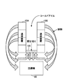
- FIG. 1 is a diagram showing an image of an exhaust heat flow of a communication device.
- FIG. 1 is a plan view of an air conditioner 20 and communication devices 10A and 10B in a communication machine room as seen from above.
- the communication device 10A and the communication device 10B each include four racks. The number of racks is an example.
- the communication device 10A and the communication device 10B are installed such that the intake surfaces (the right surface of the communication device 10A and the left surface of the communication device 10B) that suck in cool air face each other.
- the passage between the intake surface of the communication device 10A and the intake surface of the communication device 10B is called a cold aisle.
- the air conditioner 20 and the communication device 10A so that the front surface (the surface facing the communication devices 10A and 10B) of the air conditioner 20 and the intake surface of the communication devices 10A and 10B are perpendicular to each other. 10B is arranged.
- “vertical” does not have to be strictly vertical. “Vertical” may be restated as “substantially vertical”, “substantially vertical” or the like.
- FIG. 2 is a side view of the air conditioner 20 and the communication devices 10A and 10B as viewed from the side.
- the cool air delivered from the air conditioner 20 rises, is delivered from the floor surface of the cold aisle, is sucked in from the intake surfaces of the communication devices 10A and 10B, and exhaust heat is exhausted from the back faces of the communication devices 10A and 10B.
- Partition installation example 1 Therefore, in the present embodiment, as shown in FIG. 3, a partition 100 is installed at the entrance of the cold aisle on the side facing the air conditioner 20. That is, as shown in FIG. 3, a partition 100 is provided between the cold aisle side corner of the air conditioner 20 side end surface of the communication device 10A and the cold aisle side corner of the air conditioner 20 side end surface of the communication device 10B. Set up. As can be seen by comparing FIG. 1 and FIG. 3, by installing the partition 100, it is possible to prevent the exhaust heat from the air conditioner 20 side from flowing into the intake surface.
- FIG. 4 is a perspective view of the air conditioner 20 and the communication devices 10A and 10B when the partition 100 is installed, as viewed obliquely from above.
- the partition 100 is installed at the entrance of the passage (cold aisle) on the side facing the air conditioner 20.
- the partition 100 has a rectangular shape, the lower end of which is in contact with the floor, and its height is the same as the height of the communication devices 10A and 10B.
- the lower end of the partition 100 need not be in contact with the floor surface as long as it is possible to prevent exhaust heat from flowing into the intake surface.
- the height of the partition 100 may be higher or lower than the height of the communication devices 10A and 10B within a certain threshold range. Further, the thickness of the partition 100 is not particularly limited as long as it can maintain its shape.
- the structure of the partition 100 is such that a person can enter and leave the passage between the communication devices 10A and 10B and work on the communication devices 10A and 10B.
- a goodwill type, a roll screen type, a bellows type structure or the like can be used.
- a double door system or a single door system that opens and closes may be used.
- making the structure of the partition 100 into a structure that allows the partition 100 to enter and exit is an example, and may be a structure (fixed structure) in which the partition 100 cannot enter and exit.
- the material of the partition 100 may be any material to prevent exhaust heat from wrapping around, but it is preferable to use a material that ensures flame resistance, flame retardancy, and heat resistance.
- any method can be used.
- a portion indicated by C the right end corner portion of the end face of the communication device 10A on the air conditioner side
- a portion indicated by D the air conditioner of the communication device 10B
- a member to which the partition 100 is attached may be provided on both the left end corner portion of the side end surface) or C and D, and the partition 100 may be attached to the member.
- the partition 100 is shown to be a member without a window, but this is an example.
- a window may be provided in a portion that does not affect the prevention of exhaust heat from flowing around.
- FIG. 5 shows an example in which there is no gap between the partition 100 and the sides of the communication devices 10A and 10B, there may be a gap in a range that does not affect the prevention of exhaust heat wraparound.
- FIG. 6 is a diagram showing another example of the partition 100.
- the partition 100 shown in FIG. 6 includes a front partition 110 installed on the front surface of the air conditioner 20 corresponding to the partition 100 described with reference to FIG. Moreover, it has an upper partition 120 installed on the air conditioner 20 side of the communication devices 10A and 10B. By additionally providing the upper partition 120, it is possible to prevent exhaust heat from entering from the upper part, and obtain a higher effect of preventing exhaust heat from entering.
- the front partition 110 is the same as the partition 100 described in the first partition example.
- the upper partition 120 is made movable by adopting a roll screen type or the like so as not to affect workability, for example.
- the movable structure is an example, and a non-movable structure such as a plate or a sheet may be used.
- the thickness of the upper partition 120 is not particularly limited as long as it can maintain its shape.
- any method can be used.
- a portion indicated by E the right end corner portion of the upper surface of the communication device 10A
- a portion indicated by F the left end corner portion of the upper surface of the communication device 10B
- both E and F a member for attaching the upper partition 120
- the front partition 110 and the upper partition 120 may be connected to each other, or may be separated via a certain gap (a range that does not affect the prevention of exhaust heat wraparound). Further, the front partition 110 and the upper partition 120 may be an integral member.
- FIG. 7 shows an example in which there is no gap between the upper partition 120 and the sides of the communication devices 10A and 10B, but there may be a gap in a range that does not affect the prevention of exhaust heat wraparound.
- the depth of the upper partition 120 (L in FIG. 7) can be determined as a length that can effectively prevent the exhaust heat wraparound by observing the exhaust heat wraparound from the upper part.
- the depth of the upper partition 120 may be about one rack, as shown in FIG. Note that the depth of the upper partition 120 is about one rack, which is only an example.
- the partition is installed not in the entire cold aisle but only in the portion that is easily affected by the circulation of exhaust heat. As a result, it is possible to realize a low price and to prevent exhaust heat from wrapping around, which enables simple operation. In addition, safety is improved because a closed space is not formed. As a result, it contributes to the improvement of air conditioning efficiency in the communication machine room.
- (Section 4) A partition for preventing exhaust heat from flowing into a machine room in which an air conditioner and an ICT device are installed, A partition installed on the side facing the air conditioner in the passage between the two ICT devices installed so that the intake surfaces face each other.
- path is a cold aisle, The said partition is a partition provided in the entrance of the side facing the said air conditioner in the said cold aisle.
- the partition according to claim 4 or 5 further comprising an upper partition installed on a part of the passage on the side of the air conditioner.
Landscapes
- Engineering & Computer Science (AREA)
- General Engineering & Computer Science (AREA)
- Computer Hardware Design (AREA)
- Physics & Mathematics (AREA)
- Thermal Sciences (AREA)
- Microelectronics & Electronic Packaging (AREA)
- Chemical & Material Sciences (AREA)
- Combustion & Propulsion (AREA)
- Mechanical Engineering (AREA)
- Cooling Or The Like Of Electrical Apparatus (AREA)
- Central Air Conditioning (AREA)
- Air-Flow Control Members (AREA)
Abstract
空調機とICT装置とが設置される機械室において、吸気面同士が向い合うように設置された2つのICT装置の間の通路における前記空調機に面した側に間仕切りを設置するようにする。
Description
本発明は、機械室における省電力化に関し、特に、空調機の省電力化に関連するものである。
データセンタや通信機械室では、運用する通信装置の故障を防ぐため、通信装置が発する熱への対策を講じる必要があり、多くの場合、空調機を使用して通信装置を冷却する。
一方、省電力の観点からは、空調機が使用する電力量を削減するため、空調を効率的に使用することが望ましい。空調効率を向上させる気流設計方法の一つに、空調機が吐き出す冷気と、通信装置が排出する熱気とを明確に区分けする「アイルキャッピング(登録商標)」がある(非特許文献1)。
非特許文献1に開示されている「アイルキャッピング(登録商標)」は、通信装置の吸気面同士を向かい合わせた通路であるコールドアイルを囲った空間を作り、排熱の回り込みを防止する方法である。
http://www.ntt-f.co.jp/service/data_center/aco_aislecapping/、平成30年12月10日検索
非特許文献1に開示されている方法によれば、排熱の回り込み防止に対しては高い効果が期待できるが、コールドアイルを形成する空間の天井部分の設備及び両側面部分の設備を設置する必要があり、設置工事費用が高額になることが多い。
また、常時閉じた空間になるため、通信装置のメンテナンス等の作業時には出入りの度に開閉が必要となり、運用が煩雑となる。
本発明は、上記の点に鑑みてなされたものであり、空調機と複数のICT装置とが設置される機械室において、低価格で実現でき、簡易な運用を可能とする排熱回り込み防止技術を提供することを目的とする。
開示の技術によれば、空調機とICT装置とが設置される機械室における排熱回り込み防止方法であって、
吸気面同士が向い合うように設置された2つのICT装置の間の通路における前記空調機に面した側に間仕切りを設置する排熱回り込み防止方法が提供される。
吸気面同士が向い合うように設置された2つのICT装置の間の通路における前記空調機に面した側に間仕切りを設置する排熱回り込み防止方法が提供される。
開示の技術によれば、低価格で実現でき、簡易な運用を可能とする排熱回り込み防止技術を提供することができる。
以下、図面を参照して本発明の実施の形態を説明する。以下で説明する実施の形態は一例に過ぎず、本発明が適用される実施の形態は、以下の実施の形態に限られるわけではない。
例えば、以下の実施の形態では、通信機械室に設置された通信装置の冷却に対して本発明を適用することを想定しているが、本発明は、通信機械室及び通信装置に限らず、各種の機械室、及び各種のICT(Information and Communications Technology)装置に適用可能である。そのような機械室として、例えば、通信機械室、コンピュータルーム、サーバルーム等がある。ICT装置としては、例えば、交換機、スイッチ、ルータ等の通信装置、サーバ、コンピュータ、パッチパネル、パッチパネル制御ロボット等がある。また、本実施の形態では、二重床方式の通信機械室を想定しているが、本発明は二重床方式でない床を使用する場合にも適用可能である。
また、本実施の形態では、通信装置は、ラックに搭載されていることを想定しているが、そのような形態は一例である。例えば、通信装置自体がラックのような形状を有する形態であってもよいし、ラック等を使用せずに通信装置自体を積み上げるような形態であってもよいし、その他の形態であってもよい。また、通信装置が搭載されたラックを「通信装置」と称しても良い。このような「通信装置」もICT装置の一例である。また、通信装置が搭載されたラックの列を「通信装置」と称しても良い。このような「通信装置」もICT装置の一例である。
(通信装置の排熱の課題について)
上述したとおり、本実施の形態に係る通信機械室は、二重床方式を採用しており、空調機が排出した冷気は二重床内を通過して上部に出て、通信装置の吸気面から吸い込まれる。通信装置により冷気は暖気となり、暖気が通信装置から排出される。通信装置から排出された暖気(排熱)は二重床上空間を通過し空調機に戻る。
上述したとおり、本実施の形態に係る通信機械室は、二重床方式を採用しており、空調機が排出した冷気は二重床内を通過して上部に出て、通信装置の吸気面から吸い込まれる。通信装置により冷気は暖気となり、暖気が通信装置から排出される。通信装置から排出された暖気(排熱)は二重床上空間を通過し空調機に戻る。
図1は、通信装置の排熱の気流イメージを示す図である。図1は、通信機械室における空調機20、及び通信装置10A、10Bを上から見た平面図である。通信装置10Aと通信装置10Bはそれぞれ4つのラックからなる。なお、ラックの数は例である。
通信装置10Aと通信装置10Bは、冷気を吸い込む吸気面(通信装置10Aの右側の面、通信装置10Bの左側の面)が向い合せに設置されている。通信装置10Aの吸気面と通信装置10Bの吸気面との間の通路をコールドアイルと呼ぶ。
図1に示すように、空調機20の正面(通信装置10A、10Bに向かう側の面)と、通信装置10A、10Bの吸気面とが垂直になるように空調機20、及び通信装置10A、10Bが配置されている。ただし、「垂直」とは厳密な垂直である必要はない。「垂直」を「ほぼ垂直」、「略垂直」等と言い換えても良い。
図2は、空調機20、及び通信装置10A、10Bを横から見た側面図である。空調機20から送出された冷気は上昇し、コールドアイルの床面から送出され、通信装置10A、10Bの吸気面から吸い込まれ、通信装置10A、10Bの背面から排熱が排出される。
図1に示したように、通信装置10A、10Bの排熱は空調機20に向けて戻るため、一部の排熱は空調機20に近い側の通信装置10A、10Bの吸気面の部分へ回り込むことがある。そのため、その部分における通信装置10A、10Bの冷気の吸気が阻害されることがある。
(間仕切りの設置例1)
そこで、本実施の形態では、図3に示すように、コールドアイルの空調機20に面した側の出入口に間仕切り100を設置する。すなわち、図3のように、通信装置10Aの空調機20側の端面のコールドアイル側の角部分と、通信装置10Bの空調機20側の端面のコールドアイル側の角部分との間に間仕切り100を設置する。図1と図3を比較してわかるように、間仕切り100を設置することで、空調機20側からの排熱の吸気面への回り込みを防止することができる。
そこで、本実施の形態では、図3に示すように、コールドアイルの空調機20に面した側の出入口に間仕切り100を設置する。すなわち、図3のように、通信装置10Aの空調機20側の端面のコールドアイル側の角部分と、通信装置10Bの空調機20側の端面のコールドアイル側の角部分との間に間仕切り100を設置する。図1と図3を比較してわかるように、間仕切り100を設置することで、空調機20側からの排熱の吸気面への回り込みを防止することができる。
図4は、間仕切り100を設置した場合における、空調機20、通信装置10A、10Bを斜め上から見た斜視図である。
図4に示すように、間仕切り100は、空調機20に面した側の通路(コールドアイル)の出入口に設置する。
図4に示す例では、間仕切り100は、長方形の形状であり、その下端が床面に接し、その高さは通信装置10A、10Bの高さと同じである。ただし、これは一例である。排熱の吸気面への回り込みを防止できるのであれば、間仕切り100の下端が床面に接していなくてもよい。また、間仕切り100の高さは、ある閾値の範囲内で、通信装置10A、10Bの高さよりも高くてもよいし、低くてもよい。また、間仕切り100の厚さは特に限定はなく、形状を保つことができる程度の厚さがあればよい。
間仕切り100の構造は、人が通信装置10Aと10B間の通路に出入りして、通信装置10A、10Bに対する作業をすることを可能とするために、出入り可能な構造とする。具体的には、のれん式、ロールスクリーン式、ジャバラ式等の構造を用いることができる。また、両開き又は片開きで開閉する扉の方式であってもよい。なお、間仕切り100の構造を出入り可能な構造とすることは例であり、間仕切り100が出入り不可能な構造(固定構造)であってもよい。
また、間仕切り100の材質ついて、排熱の回り込み防止のためにはどのような材質であってもよいが、防炎性・難燃性・耐熱性を確保する材質とすることが望ましい。
また、間仕切りを図4に示す位置に設置する方法としては、任意の方法を用いることができる。例えば、図5(間仕切り100を空調機20の側から見た正面図)のCで示す部分(通信装置10Aの空調機側端面の右端角部分)あるいはDで示す部分(通信装置10Bの空調機側端面の左端角部分)あるいはCとDの両方に、間仕切り100を取り付ける部材を備え、その部材に間仕切り100を取り付けるようにすることができる。
なお、図5の例では、間仕切り100が窓のない部材であることが示されているが、これは例である。例えば、排熱回り込み防止に影響のない部分に窓を設けても良い。また、図5は、間仕切り100と通信装置10A、10Bの横との間に隙間がない例を示しているが、排熱回り込み防止に影響のない範囲で隙間があってもよい。
(間仕切りの設置例2)
図6は、間仕切り100の他の例を示す図である。図6に示す間仕切り100は、間仕切りの設置例1として図4等で説明した間仕切り100に相当する空調機20の前面に設置される前部間仕切り110と、通信装置10A、10Bの吸気面上部(かつ、通信装置10A、10Bの空調機20の側)に設置される上部間仕切り120を有する。上部間仕切り120を追加で備えることで、上部からの排熱回り込みを防ぐことができ、より高い排熱回り込み防止効果を得ることができる。
図6は、間仕切り100の他の例を示す図である。図6に示す間仕切り100は、間仕切りの設置例1として図4等で説明した間仕切り100に相当する空調機20の前面に設置される前部間仕切り110と、通信装置10A、10Bの吸気面上部(かつ、通信装置10A、10Bの空調機20の側)に設置される上部間仕切り120を有する。上部間仕切り120を追加で備えることで、上部からの排熱回り込みを防ぐことができ、より高い排熱回り込み防止効果を得ることができる。
前部間仕切り110は、間仕切りの例1で説明した間仕切り100と同様のものである。上部間仕切り120は、例えば、作業性に影響を与えないようにするために、ロールスクリーン式等を採用することで可動式とする。ただし、可動式であることは例であり、板あるいはシートのような非可動式の構造を用いても良い。上部間仕切り120の厚さは特に限定はなく、形状を保つことができる程度の厚さがあればよい。
上部間仕切り120を図6に示す位置に設置する方法としては、任意の方法を用いることができる。例えば、図7(上から見た平面図)のEで示す部分(通信装置10Aの上面の右端角部分)あるいはFで示す部分(通信装置10Bの上面の左端角部分)あるいはEとFの両方に、上部間仕切り120を取り付ける部材を備え、その部材に上部間仕切り120を取り付けるようにしてもよい。なお、前部間仕切り110と上部間仕切り120とは接続されていてもよいし、ある程度の隙間(排熱回り込み防止に影響のない範囲)を介して切り離されていてもよい。また、前部間仕切り110と上部間仕切り120が一体の部材であってもよい。
図7は、上部間仕切り120と通信装置10A、10Bの横との間に隙間がない例を示しているが、排熱回り込み防止に影響のない範囲で隙間があってもよい。
上部間仕切り120の奥行の長さ(図7のL)は、例えば、上部からの排熱回り込みを観測することで、その排熱回り込みを効果的に防止できる長さとして決定することができる。例えば、上部間仕切り120の奥行の長さは、図7に示すように、1ラック分程度の長さとしてもよい。なお、上部間仕切り120の奥行の長さが1ラック分程度の長さであることは一例に過ぎない。
(実施の形態の効果)
以上説明したとおり、本実施の形態では、コールドアイル全体ではなく、排熱の回り込みの影響を受けやすい部分のみに間仕切りを設置することとした。これにより、低価格を実現し、かつ、簡易な運用を可能とする排熱の回り込み防止を実現できる。また、閉じた空間を形成しないため、安全性も向上する。結果として、通信機械室における空調効率改善に寄与する。
以上説明したとおり、本実施の形態では、コールドアイル全体ではなく、排熱の回り込みの影響を受けやすい部分のみに間仕切りを設置することとした。これにより、低価格を実現し、かつ、簡易な運用を可能とする排熱の回り込み防止を実現できる。また、閉じた空間を形成しないため、安全性も向上する。結果として、通信機械室における空調効率改善に寄与する。
すなわち、通信装置の吸気面への排熱の回り込みを簡易な構造で防ぐことができ、機械室の作業性を低下させることなく空調効率を改善することが可能となる。
(実施の形態のまとめ)
本明細書には、少なくとも下記の事項が開示されている。
(第1項)
空調機とICT装置とが設置される機械室における排熱回り込み防止方法であって、
吸気面同士が向い合うように設置された2つのICT装置の間の通路における前記空調機に面した側に間仕切りを設置する排熱回り込み防止方法。
(第2項)
前記通路はコールドアイルであり、当該コールドアイルにおける前記空調機に面した側の出入口に前記間仕切りを設置する
第1項に記載の排熱回り込み防止方法。
(第3項)
前記通路における前記空調機の側の一部の上部に上部間仕切りを更に設置する
第1項又は第2項に記載の排熱回り込み防止方法。
(第4項)
空調機とICT装置とが設置される機械室における排熱回り込み防止のための間仕切りであって、
吸気面同士が向い合うように設置された2つのICT装置の間の通路における前記空調機に面した側に設置される間仕切り。
(第5項)
前記通路はコールドアイルであり、前記間仕切りは、当該コールドアイルにおける前記空調機に面した側の出入口に設置される
第4項に記載の間仕切り。
(第6項)
前記通路における前記空調機の側の一部の上部に設置される上部間仕切りを更に有する
第4項又は第5項に記載の間仕切り。
本明細書には、少なくとも下記の事項が開示されている。
(第1項)
空調機とICT装置とが設置される機械室における排熱回り込み防止方法であって、
吸気面同士が向い合うように設置された2つのICT装置の間の通路における前記空調機に面した側に間仕切りを設置する排熱回り込み防止方法。
(第2項)
前記通路はコールドアイルであり、当該コールドアイルにおける前記空調機に面した側の出入口に前記間仕切りを設置する
第1項に記載の排熱回り込み防止方法。
(第3項)
前記通路における前記空調機の側の一部の上部に上部間仕切りを更に設置する
第1項又は第2項に記載の排熱回り込み防止方法。
(第4項)
空調機とICT装置とが設置される機械室における排熱回り込み防止のための間仕切りであって、
吸気面同士が向い合うように設置された2つのICT装置の間の通路における前記空調機に面した側に設置される間仕切り。
(第5項)
前記通路はコールドアイルであり、前記間仕切りは、当該コールドアイルにおける前記空調機に面した側の出入口に設置される
第4項に記載の間仕切り。
(第6項)
前記通路における前記空調機の側の一部の上部に設置される上部間仕切りを更に有する
第4項又は第5項に記載の間仕切り。
以上、本実施の形態について説明したが、本発明はかかる特定の実施形態に限定されるものではなく、特許請求の範囲に記載された本発明の要旨の範囲内において、種々の変形・変更が可能である。
10A、10B 通信装置
20 空調機
100 間仕切り
110 前部間仕切り
120 上部間仕切り
20 空調機
100 間仕切り
110 前部間仕切り
120 上部間仕切り
Claims (6)
- 空調機とICT装置とが設置される機械室における排熱回り込み防止方法であって、
吸気面同士が向い合うように設置された2つのICT装置の間の通路における前記空調機に面した側に間仕切りを設置する排熱回り込み防止方法。 - 前記通路はコールドアイルであり、当該コールドアイルにおける前記空調機に面した側の出入口に前記間仕切りを設置する
請求項1に記載の排熱回り込み防止方法。 - 前記通路における前記空調機の側の一部の上部に上部間仕切りを更に設置する
請求項1又は2に記載の排熱回り込み防止方法。 - 空調機とICT装置とが設置される機械室における排熱回り込み防止のための間仕切りであって、
吸気面同士が向い合うように設置された2つのICT装置の間の通路における前記空調機に面した側に設置される間仕切り。 - 前記通路はコールドアイルであり、前記間仕切りは、当該コールドアイルにおける前記空調機に面した側の出入口に設置される
請求項4に記載の間仕切り。 - 前記通路における前記空調機の側の一部の上部に設置される上部間仕切りを更に有する
請求項4又は5に記載の間仕切り。
Priority Applications (1)
| Application Number | Priority Date | Filing Date | Title |
|---|---|---|---|
| US17/312,544 US20220061190A1 (en) | 2018-12-12 | 2019-12-09 | Waste heat wraparound prevention method and partition |
Applications Claiming Priority (2)
| Application Number | Priority Date | Filing Date | Title |
|---|---|---|---|
| JP2018-232929 | 2018-12-12 | ||
| JP2018232929A JP2020094743A (ja) | 2018-12-12 | 2018-12-12 | 排熱回り込み防止方法、及び間仕切り |
Publications (1)
| Publication Number | Publication Date |
|---|---|
| WO2020122021A1 true WO2020122021A1 (ja) | 2020-06-18 |
Family
ID=71077235
Family Applications (1)
| Application Number | Title | Priority Date | Filing Date |
|---|---|---|---|
| PCT/JP2019/048110 Ceased WO2020122021A1 (ja) | 2018-12-12 | 2019-12-09 | 排熱回り込み防止方法、及び間仕切り |
Country Status (3)
| Country | Link |
|---|---|
| US (1) | US20220061190A1 (ja) |
| JP (1) | JP2020094743A (ja) |
| WO (1) | WO2020122021A1 (ja) |
Citations (4)
| Publication number | Priority date | Publication date | Assignee | Title |
|---|---|---|---|---|
| US20050193761A1 (en) * | 2004-03-04 | 2005-09-08 | Vogel Marlin R. | Data center room cold aisle deflector |
| JP2011190987A (ja) * | 2010-03-15 | 2011-09-29 | Taisei Corp | 空調システム |
| KR101491307B1 (ko) * | 2013-08-30 | 2015-02-10 | (주) 아이커머 | 데이터센터의 공조 시스템 |
| JP2016196980A (ja) * | 2015-04-03 | 2016-11-24 | 株式会社竹中工務店 | 空調システム |
Family Cites Families (8)
| Publication number | Priority date | Publication date | Assignee | Title |
|---|---|---|---|---|
| JP3835615B2 (ja) * | 2002-11-21 | 2006-10-18 | 株式会社Nttファシリティーズ | 電算機室用空調システム |
| JP4795402B2 (ja) * | 2008-07-18 | 2011-10-19 | 株式会社Nttファシリティーズ | 電算機室用空調システム |
| JP5557755B2 (ja) * | 2011-01-14 | 2014-07-23 | エヌ・ティ・ティ・コムウェア株式会社 | 機器収容システム用エンドキャップ |
| US11246231B2 (en) * | 2012-02-10 | 2022-02-08 | Chatsworth Products, Inc. | Door closer mechanism for hot/cold aisle air containment room |
| US9255417B2 (en) * | 2014-03-12 | 2016-02-09 | Panduit Corp. | Independent aisle containment system |
| WO2015138866A1 (en) * | 2014-03-13 | 2015-09-17 | Upsite Technologies, Inc. | Adjustable airflow barrier system |
| WO2018097730A1 (en) * | 2016-11-28 | 2018-05-31 | Solo30 B.V. | Datacentre |
| US9888606B1 (en) * | 2016-12-19 | 2018-02-06 | Microsoft Technology Licensing, Llc | Automated panel for cold aisle containment |
-
2018
- 2018-12-12 JP JP2018232929A patent/JP2020094743A/ja active Pending
-
2019
- 2019-12-09 US US17/312,544 patent/US20220061190A1/en not_active Abandoned
- 2019-12-09 WO PCT/JP2019/048110 patent/WO2020122021A1/ja not_active Ceased
Patent Citations (4)
| Publication number | Priority date | Publication date | Assignee | Title |
|---|---|---|---|---|
| US20050193761A1 (en) * | 2004-03-04 | 2005-09-08 | Vogel Marlin R. | Data center room cold aisle deflector |
| JP2011190987A (ja) * | 2010-03-15 | 2011-09-29 | Taisei Corp | 空調システム |
| KR101491307B1 (ko) * | 2013-08-30 | 2015-02-10 | (주) 아이커머 | 데이터센터의 공조 시스템 |
| JP2016196980A (ja) * | 2015-04-03 | 2016-11-24 | 株式会社竹中工務店 | 空調システム |
Also Published As
| Publication number | Publication date |
|---|---|
| JP2020094743A (ja) | 2020-06-18 |
| US20220061190A1 (en) | 2022-02-24 |
Similar Documents
| Publication | Publication Date | Title |
|---|---|---|
| JP4843578B2 (ja) | 空調システム | |
| EP3849293A1 (en) | Closed cold pool system | |
| US9615488B1 (en) | Datacenter aisle containment structure | |
| US20110237174A1 (en) | Device for cooling and conditioning an environment containing a plurality of heat emitting bodies, particularly for server rooms and the like | |
| JP5264432B2 (ja) | ラック間通路遮蔽構造 | |
| CN105792602A (zh) | 机柜及其通风方法 | |
| US20110250831A1 (en) | Air-conditioning system and air conditioner thereof | |
| CN102386571B (zh) | 变压器的冷却装置 | |
| KR101402056B1 (ko) | 엘리베이터 홀도어의 디스플레이용 환기장치 | |
| CN105828580A (zh) | 一种可单独调节机柜散热的组合机柜 | |
| JP2020094743A (ja) | 排熱回り込み防止方法、及び間仕切り | |
| JP6275950B2 (ja) | 情報通信機械室の空調システム | |
| WO2014025043A1 (ja) | ラック列通路遮蔽構造 | |
| JP2011172357A (ja) | スイッチギヤの換気装置 | |
| JP2013210170A (ja) | 空調システム | |
| JP2011129008A (ja) | 発熱機器用のラック空調装置ユニット及びラック空調装置 | |
| JP2010168769A (ja) | ラック間通路遮へい構造 | |
| JP6081731B2 (ja) | 情報処理機器室の空調システム | |
| JP2014031974A (ja) | 情報処理機器室の空調システム | |
| CN207459035U (zh) | 一种便于维护的储能电池柜 | |
| JP3820176B2 (ja) | 熱電素子を用いたコンピュータの個別分散型冷却装置 | |
| JP5659373B2 (ja) | 気流制御板 | |
| JP2021034421A (ja) | 通路閉塞装置 | |
| JP6430723B2 (ja) | サーバー室内の空調の効率化構造 | |
| JP2011134803A (ja) | 電子機器収納ラック群の冷却装置及び方法 |
Legal Events
| Date | Code | Title | Description |
|---|---|---|---|
| 121 | Ep: the epo has been informed by wipo that ep was designated in this application |
Ref document number: 19894866 Country of ref document: EP Kind code of ref document: A1 |
|
| NENP | Non-entry into the national phase |
Ref country code: DE |
|
| 122 | Ep: pct application non-entry in european phase |
Ref document number: 19894866 Country of ref document: EP Kind code of ref document: A1 |