WO2020121978A1 - Outer layer cladding material for heat exchanger having exceptional corrosion resistance in root portion, and heat exchanger - Google Patents
Outer layer cladding material for heat exchanger having exceptional corrosion resistance in root portion, and heat exchanger Download PDFInfo
- Publication number
- WO2020121978A1 WO2020121978A1 PCT/JP2019/047912 JP2019047912W WO2020121978A1 WO 2020121978 A1 WO2020121978 A1 WO 2020121978A1 JP 2019047912 W JP2019047912 W JP 2019047912W WO 2020121978 A1 WO2020121978 A1 WO 2020121978A1
- Authority
- WO
- WIPO (PCT)
- Prior art keywords
- heat exchanger
- brazing
- corrosion resistance
- clad material
- potential
- Prior art date
Links
Images

Classifications
-
- B—PERFORMING OPERATIONS; TRANSPORTING
- B23—MACHINE TOOLS; METAL-WORKING NOT OTHERWISE PROVIDED FOR
- B23K—SOLDERING OR UNSOLDERING; WELDING; CLADDING OR PLATING BY SOLDERING OR WELDING; CUTTING BY APPLYING HEAT LOCALLY, e.g. FLAME CUTTING; WORKING BY LASER BEAM
- B23K1/00—Soldering, e.g. brazing, or unsoldering
-
- B—PERFORMING OPERATIONS; TRANSPORTING
- B23—MACHINE TOOLS; METAL-WORKING NOT OTHERWISE PROVIDED FOR
- B23K—SOLDERING OR UNSOLDERING; WELDING; CLADDING OR PLATING BY SOLDERING OR WELDING; CUTTING BY APPLYING HEAT LOCALLY, e.g. FLAME CUTTING; WORKING BY LASER BEAM
- B23K35/00—Rods, electrodes, materials, or media, for use in soldering, welding, or cutting
- B23K35/22—Rods, electrodes, materials, or media, for use in soldering, welding, or cutting characterised by the composition or nature of the material
- B23K35/24—Selection of soldering or welding materials proper
- B23K35/28—Selection of soldering or welding materials proper with the principal constituent melting at less than 950 degrees C
-
- C—CHEMISTRY; METALLURGY
- C22—METALLURGY; FERROUS OR NON-FERROUS ALLOYS; TREATMENT OF ALLOYS OR NON-FERROUS METALS
- C22C—ALLOYS
- C22C21/00—Alloys based on aluminium
-
- F—MECHANICAL ENGINEERING; LIGHTING; HEATING; WEAPONS; BLASTING
- F28—HEAT EXCHANGE IN GENERAL
- F28F—DETAILS OF HEAT-EXCHANGE AND HEAT-TRANSFER APPARATUS, OF GENERAL APPLICATION
- F28F19/00—Preventing the formation of deposits or corrosion, e.g. by using filters or scrapers
- F28F19/02—Preventing the formation of deposits or corrosion, e.g. by using filters or scrapers by using coatings, e.g. vitreous or enamel coatings
- F28F19/06—Preventing the formation of deposits or corrosion, e.g. by using filters or scrapers by using coatings, e.g. vitreous or enamel coatings of metal
-
- F—MECHANICAL ENGINEERING; LIGHTING; HEATING; WEAPONS; BLASTING
- F28—HEAT EXCHANGE IN GENERAL
- F28F—DETAILS OF HEAT-EXCHANGE AND HEAT-TRANSFER APPARATUS, OF GENERAL APPLICATION
- F28F21/00—Constructions of heat-exchange apparatus characterised by the selection of particular materials
- F28F21/08—Constructions of heat-exchange apparatus characterised by the selection of particular materials of metal
-
- F—MECHANICAL ENGINEERING; LIGHTING; HEATING; WEAPONS; BLASTING
- F28—HEAT EXCHANGE IN GENERAL
- F28F—DETAILS OF HEAT-EXCHANGE AND HEAT-TRANSFER APPARATUS, OF GENERAL APPLICATION
- F28F9/00—Casings; Header boxes; Auxiliary supports for elements; Auxiliary members within casings
- F28F9/02—Header boxes; End plates
Definitions
- the present invention relates to a heat exchanger multilayer clad material and a heat exchanger that have excellent corrosion resistance at the root after brazing.
- the header plate material for the heat exchanger an aluminum alloy composed of three layers, in which a core material, a brazing material for joining with other members, and a sacrificial material in contact with cooling water are laminated, is used (for example, see Patent Documents 1 to 3).
- the header plate material is required to have high strength, and an Al—Mn alloy is used for the core material, and the strength is improved by adding elements such as Mg and Cu.
- Mg forms an oxide film by combining with oxygen in the atmosphere during brazing and reduces the brazing property.
- Cu condenses into fillets formed at the joint between the header plate and the tube to make the electric potential noble, so that the tube near the joint where the electric potential is relatively base is penetrated early, which reduces corrosion resistance.
- a brazing sheet has been proposed in which the distribution of the Si-based precipitate and the eutectic phase of the brazing material after brazing is appropriately adjusted to significantly improve the corrosion resistance (see Patent Document 4).
- the present invention has been made in view of the above circumstances, and an object of the present invention is to provide a multilayer clad material for a heat exchanger and a heat exchanger that have high strength and excellent corrosion resistance at the root.
- the first mode is that each is made of an aluminum alloy, and at least a brazing material and a core material are laminated to form a brazing target material.
- a multilayer clad material for a heat exchanger to be brazed When the potential of the core material is E1, the potential of the eutectic braze of the fillet formed at the joint between the brazing target material and the multilayer clad material for heat exchanger is E3, and the potential of the brazing target material is E2, E3 ⁇ E1 ⁇ E2, and the potential difference ⁇ E A between E3 and E2 is 105 mV or more, and the potential difference ⁇ E B between E3 and E1 is 80 mV or more.
- Another aspect of the invention of a multilayer clad material for a heat exchanger having excellent corrosion resistance of a root portion is the invention of the above aspect, in which the core material is mass%, Mn: 1.2 to 2.0%, Cu: 0. 3 to 1.0%, Si: 0.5 to 1.2%, with the balance being Al and inevitable impurities.
- Another aspect of the invention is a multilayer clad material for a heat exchanger, which has excellent corrosion resistance of a rooted portion, in the invention of the above aspect, the brazing filler metal is mass%, Si: 5.0 to 12.0%, Zn: 1 0.0 to 5.0%, with the balance being Al and unavoidable impurities.
- the invention of a multilayer clad material for a heat exchanger having excellent corrosion resistance of a rooted portion of another aspect is that in the invention of the aspect, a sacrificial material is laminated on the other surface side of the core material on which a brazing material is laminated. Is characterized by.
- Another aspect of the invention of a multilayer clad material for a heat exchanger having excellent corrosion resistance of a root portion is the invention of the above aspect, in which the sacrificial material is mass%, Mn: 1.2 to 2.0%, Si:0. 0.5 to 1.2%, Zn: 0.05 to 0.5%, with the balance being Al and inevitable impurities.
- the sacrificial material is arranged in contact with the packing when used for a heat exchanger.
- the sacrificial material is an Al—Mn—Si-based compound having a circle equivalent diameter of 0.1 ⁇ m to 0.5 ⁇ m. 1 to 100/ ⁇ m 2 .
- Another aspect of the invention of a multilayer clad material for a heat exchanger, which has excellent corrosion resistance of a rooted portion, is the same as the multilayer clad material for a heat exchanger according to the invention of the above aspect, to which a working strain of 2 to 8% is applied during brazing.
- the erosion rate of the wax is 10% or less of the plate thickness.
- the recrystallized grain size of the core material after brazing is 40 ⁇ m or more in the direction horizontal to the rolling direction. ..
- the brazing holding temperature is 590°C to 610°C in the above aspect of the invention.
- the core material to be brazed is an Al—Mn-based alloy, and in a mass %, Cu:0. 0.1 to 1.0% is contained.
- the material is used as a header plate, and the brazing target material is a tube material.
- the header plate made of the multilayer clad material for heat exchangers of any of the above aspects and the tube to be brazed are joined by brazing.
- each component is shown by mass %.
- the potential difference ⁇ E A between E3 and E2 is 105 mV or more
- the potential difference ⁇ E B between E3 and E1 is 80 mV or more.
- the eutectic braze does not preferentially corrode, but corrodes the core material. Therefore, the relationship of each potential is defined as above.
- the potential can be measured, for example, by the following method.
- the potential is the pitting potential obtained by the following method. For example, 10 mm 2 of the measurement portion of each portion subjected to the heat treatment for brazing and the conductive portion were exposed, and the other portions were covered with an insulating paint.
- an aqueous solution containing 2.67% of AlCl 3 is used, platinum is used for the counter electrode, and saturated calomel is used for the reference electrode. Since the saturated calomel reference electrode affects the aqueous solution used, the aqueous solution saturated with KCl was bypassed. The atmosphere is flushed with N 2 gas for 20 minutes to eliminate the effect of dissolved oxygen.
- the temperature of the aqueous solution is kept at 40° C. in a constant temperature bath. After holding at the natural potential for about 5 minutes, the speed is set to 0.5 mV/sec and the potential is swept by 1000 mV. As the pitting potential, the electric potential at the point connecting the respective tangents to the passive state holding current density and the subsequent point where the current flows is selected, and the potential difference is calculated based on the obtained potential. In some samples containing Zn, passivation could not be confirmed depending on the added amount of Zn, and in that case, a potential of 1 mA/cm 2 was selected.
- Mn (Heartwood) Mn: 1.2-2.0% Mn is contained in order to improve the strength of the core material.
- the Mn content is less than 1.2%, the Mn content is so small that the strength of the material after brazing decreases, and the pressure resistance of the heat exchanger becomes insufficient, and the desired effect cannot be obtained.
- the Mn content exceeds 2.0%, the manufacturability (castability, rollability) deteriorates. For this reason, when Mn is contained, it is desirable to set it within the above range. For the same reason, it is desirable that the lower limit of the Mn content is 1.5% and the upper limit thereof is 1.8%.
- Si 0.5-1.2% Si is contained to improve the strength of the core material.
- Si content if the Si content is less than 0.5%, the Si content is small and the strength of the material after brazing is reduced, so that the pressure resistance of the heat exchanger is insufficient and the desired effect cannot be obtained.
- Si content exceeds 1.2%, the melting point is lowered and the brazing property is lowered. Therefore, when Si is contained, it is desirable to set it within the above range. For the same reason, it is desirable that the Si content has a lower limit of 0.8% and an upper limit of 1.0%.
- Cu 0.3-1.0% Cu is contained to improve the strength of the core material. However, if the Cu content is less than 0.3%, the content is too small to obtain the desired effect. On the other hand, when the Cu content exceeds 1.0%, the melting point decreases. For this reason, when Cu is contained, it is desirable to set it within the above range. For the same reason, it is desirable that the lower limit of the Cu content be 0.7% and the upper limit thereof be 0.9%.
- the recrystallized grain size of the core material after brazing is 40 ⁇ m or more and the recrystallized grain size is less than 40 ⁇ m in the direction horizontal to the rolling direction, the molten braze will corrode into the core material during brazing, and it will be necessary for fillet formation. Can't get Therefore, the recrystallized grain size is set to 40 ⁇ m or more.
- the homogenizing temperature of the core material is appropriately selected. For example, it can be selected at 500° C. to 600° C. for 1 to 10 hours. As the brazing holding temperature, 600° C. ⁇ 5 minutes can be shown as an example.
- the recrystallized grain size may be 200 ⁇ m so that the strength does not decrease after brazing.
- brazing material In the clad material of the present invention, a brazing material having an appropriate composition is used.
- the composition of the brazing material is not limited to a particular one, but the following can be shown as suitable components.
- Si: 5.0-12.0% Si improves brazeability.
- the Si content of the brazing material be within the above range.
- the lower limit of the Si content be 6% and the upper limit thereof be 9%.
- Zn 1.0-5.0% Zn improves the corrosion resistance and is included. However, if the content is less than 1.0%, the content is small, the potential of the fillet formed at the joint between the core material and the brazing target material becomes noble, and the potential difference between the fillet and the brazing target material becomes small, so sufficient corrosion resistance is obtained. I can't get it. On the other hand, when the Zn content exceeds 5.0%, the electric potential becomes base and the corrosion weight loss increases. Therefore, it is desirable that the Zn content of the brazing material be within the above range. For the same reason, it is preferable that the Zn content has a lower limit of 2.0% and an upper limit of 4.0%.
- Zn is added to the brazing material as a clad material having excellent corrosion resistance even in a material in which a large amount of Cu is added to the core material.
- Zn which has a base material potential, can provide a sacrificial anode action.
- Zn is concentrated in the fillet formed at the joint between the clad material and the material to be brazed, the potential of which has become noble due to the concentration of Cu, so that the potential of the fillet becomes base.
- a potential difference of E3 ⁇ E1 ⁇ E2 can be obtained. Therefore, it is possible to solve the deterioration of the corrosion resistance due to Cu added to the core material for increasing the strength.
- the clad material of the present invention may be a stack of sacrificial materials.
- the sacrificial material of the present invention is not limited to a specific composition, but the following can be shown as suitable components.
- Mn 1.2-2.0% Mn improves the strength of the sacrificial material and further improves the corrosion resistance, so it is contained. However, if the Mn content is less than 1.2%, the strength of the material after brazing decreases, and the pressure resistance of the heat exchanger becomes insufficient, and the desired effect cannot be obtained. On the other hand, if the Mn content exceeds 2.0%, the manufacturability (castability, rollability) deteriorates. Therefore, it is desirable that the Mn content be within the above range. For the same reason, it is desirable that the lower limit of the Mn content is 1.5% and the upper limit thereof is 1.8%.
- Si 0.5-1.2% Si is contained because it improves the strength of the sacrificial material and further improves the corrosion resistance.
- the Si content is less than 0.5%, the Si content is small and the strength of the material after brazing is reduced, so that the pressure resistance of the heat exchanger is insufficient and the desired effect cannot be obtained.
- it exceeds 1.2% the melting point is lowered, resulting in poor brazing. Therefore, it is desirable that the Si content be within the above range. For the same reason, it is desirable that the Si content has a lower limit of 0.8% and an upper limit of 1.0%.
- Zn 0.05-0.5% Zn is contained because it improves the corrosion resistance. However, if the Zn content is less than 0.05%, the content is too small to obtain the desired effect. On the other hand, when the Zn content exceeds 0.5%, the electric potential becomes base and the corrosion weight loss increases. Therefore, the Zn content is set within the above range. For the same reason, it is desirable that the lower limit of the Zn content be 0.3% and the upper limit thereof be 0.5%.
- Al-Mn-Si compound having a circle equivalent diameter of 0.1 ⁇ m to 0.5 ⁇ m: 1 to 100/ ⁇ m 2 If the size of the above compound is less than the equivalent circle diameter of 0.1 ⁇ m, the strength of the material after brazing decreases, and the pressure resistance of the heat exchanger becomes insufficient, and the desired effect cannot be obtained. If the equivalent circle diameter exceeds 0.5 ⁇ m, the corrosion resistance of the sacrificial material deteriorates, and the strength of the material after brazing decreases, so that the pressure resistance of the heat exchanger becomes insufficient and the desired effect cannot be obtained.
- the corrosion resistance after brazing is reduced, and the strength of the material is reduced, so that the pressure resistance of the heat exchanger is insufficient and the desired effect cannot be obtained.
- it exceeds 100 pieces/ ⁇ m 2 the corrosion resistance of the sacrificial material deteriorates, and the strength of the material after brazing decreases, so that the pressure resistance of the heat exchanger becomes insufficient and the desired effect cannot be obtained.
- the temperature of the subsequent heat treatment is preferably as low as possible in order to suppress the growth of the compound.
- the heat treatment may be performed in a batch annealing furnace at 300° C. to 450° C. for 1 to 10 hours.
- the size and number of compounds can be measured, for example, by the following method.
- a cross section parallel to the rolling direction of the brazed material is processed by using an ion milling method.
- the distribution state of the Al—Mn—Si compound in the sacrificial material is observed using a general-purpose scanning electron microscope. It is desirable to use an FE-SEM as the facility for observation so that the magnification is 10,000 to 50,000 times.
- a photograph containing at least 20 pieces in one visual field is taken, for example, about 10 visual fields.
- the area of the Al-Mn-Si-based compound was binarized in the obtained photograph and obtained by separating the particles and the base material.
- the equivalent circle diameter is calculated from the area of the obtained compound.
- a tube material is typically mentioned.
- an Al-Mn-based alloy can be used, and a material containing Cu: 0.1 to 1.0% by mass% can be shown. Since the material brazed to the header plate is generally a tube material, the above materials are typically mentioned. Al-Mn alloy is often used as the core material of the tube material, and when Cu:0.1-1.0% is contained, the potential balance is established between the header and the fillet (it becomes the most precious). ..
- the brazing object material is not limited to the above.
- the present invention by appropriately determining the potentials of the core material, the material to be brazed, and the eutectic braze, it is possible to obtain excellent corrosion resistance while maintaining high strength.
- the aluminum alloy for the core material, the aluminum alloy for the sacrificial material, and the aluminum alloy for the brazing material are cast by semi-continuous casting.
- the aluminum alloy for the core material for example, Mn: 1.2 to 2.0%, Cu: 0.3 to 1.0%, Si: 0.5 to 1.2%, and the balance is mass%.
- An alloy having a composition of Al and inevitable impurities can be used.
- an aluminum alloy for brazing material for example, an alloy containing, by mass%, Si: 5.0 to 12.0% and Zn: 1.0 to 5.0%, with the balance being Al and inevitable impurities. Can be used.
- the aluminum alloy for sacrificial material contains, for example, Mn: 1.2 to 2.0%, Si: 0.5 to 1.2%, and Zn: 0.05 to 0.5% in mass%.
- An alloy having a composition in which the balance is Al and inevitable impurities can be used.
- the compositions of the aluminum alloy for core material, the aluminum alloy for brazing material and the aluminum alloy for sacrificial material are not limited to those described above. Further, in the present invention, the sacrificial material may not be used.
- the obtained core material can be selected at 500° C. to 600° C. for 1 hour to 10 hours and homogenized.
- the brazing material can be selected and homogenized at 400° C. to 500° C. for 1 hour to 10 hours.
- the sacrificial material shall not be homogenized.
- a sacrificial material is combined with one surface of the ingot of the core material and a brazing material is combined with the other surface, and hot rolling is performed using a device of a hot rough rolling mill or a hot finish rolling mill, and an aluminum alloy clad material.
- the present invention is not limited to a specific clad rate.
- cold rolling is performed using a device of a cold finish rolling mill to a predetermined thickness.
- heat treatment is performed in a batch annealing furnace in order to set the quality of the material to O.
- the temperature of the heat treatment can be selected in the range of 300° C. to 450° C. and the time can be selected in the range of 1 to 10 hours.
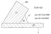
- FIG. 1 shows a cross-sectional view of the structure of the multilayer clad material 20 for a heat exchanger obtained as described above.
- the brazing material 20B is laminated on one surface of the core material 20A, and the sacrificial material 20C is laminated on the other surface of the core material 20A.
- the multilayer clad material 20 for a heat exchanger is used as a three-layer clad material for a header plate of a heat exchanger.
- the heat exchanger multilayer clad material 20 is, for example, pressed into a header plate shape, then combined with the tube material 3 and brazed, as shown in FIG.
- the brazing material 20B is melted by brazing, and is brazed to the combined tube material 3. At that time, a wax reservoir (fillet 21) is formed, and the vicinity of the fillet is called a rooted portion.
- the brazing is performed, for example, by heating the members combined in the shape of the heat exchanger from room temperature to 590 to 610° C., and after reaching a predetermined temperature, holding for 1 to 10 minutes. Then, it is a step of cooling to room temperature at a cooling rate of 30 to 150° C./min.
- all brazing conditions are not limited to particular ones.
- the surface of the sacrificial material 20C is caulked and joined to the resin tank, and packing is used at the joint interface to prevent cooling water leakage.
- packing for example, a rubber-shaped O-shaped one is used.
- the potential of the core material 20A is E1
- the potential of the tube material 3 is E2
- the potential of the eutectic braze in the fillet 21 is E3
- the relation of E3 ⁇ E1 ⁇ E2 is satisfied
- the potential difference ⁇ E between E3 and E2 is satisfied.
- A satisfies 105 mV or more
- the potential difference ⁇ E B between E3 and E1 satisfies 80 mV or more.
- the sacrificial material 20C contains 1 to 100 pieces/ ⁇ m 2 of Al—Mn—Si compound having a circle equivalent diameter of 0.1 ⁇ m to 0.5 ⁇ m, and the recrystallized grain size of the core material 20A is horizontal in the rolling direction. 40 ⁇ m or more in all directions.
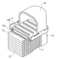
- FIG. 3 shows an assembled body for a heat exchanger in which the header plate 10 made of the multilayer clad material 20 for the heat exchanger is assembled.
- the header plate 10 has an air-side surface 10a made of a brazing material and a refrigerant-side surface 10b made of a sacrificial material, and many tubes 11 are fitted from the air-side surface 10a side. The tip of the tube 11 is projected beyond the surface 10b on the refrigerant side. Fins 12 are arranged between the tubes 11 on the air side and are in close contact with the tubes 11.
- a resin tank 14 is arranged on the refrigerant side of the header plate 10 so as to cover the protruding portion of the tube 11, and a rubber packing 13 seals between the resin tank 14 and the header plate 10.
- the tank may be made of an aluminum alloy material, and the aluminum alloy material of the present invention may be used as the material.
- the assembled body can be brazed by a conventional method. It should be noted that the present invention is not particularly limited in terms of heating conditions, atmosphere, type of flux, etc. in brazing.
- the fins 12 are brazed to the tube 11, the aluminum alloy brazing material of the header plate 10 is melted, the flow of the brazing is appropriately suppressed, and the fitting of the tube 11 is well performed. To be done.
- the refrigerant flows into each tube 11 through the inside of the resin tank 14. At this time, the header plate 10 in contact with the refrigerant exhibits good corrosion resistance regardless of whether it is alkaline or acidic due to the eutectic phase.
- the excellent multilayer clad material for heat exchanger is used for the header plate, but the present invention is not limited to the header plate.
- An aluminum alloy for a core material, an aluminum alloy for a sacrificial material, and an aluminum alloy for a brazing material having the compositions shown in Table 1 (the balance being Al and unavoidable impurities) were melted by a semi-continuous casting method.
- the obtained core material was selected at 550 to 600° C. for 5 to 10 hours and homogenized.
- the sacrificial material was not homogenized.
- the brazing material was homogenized at 400 to 500° C. for 1 to 10 hours.
- the sacrificial material is combined with one surface of the ingot of the core material and the brazing material on the other surface, and hot rolling is performed using a device of a hot rough rolling machine or a hot finish rolling machine.
- Brazing material 10%: 80%: Laminated with a clad ratio of 10%.
- cold rolling was performed to a thickness of 1 to 2 mm using a device of a cold finish rolling mill.
- heat treatment was performed at 300° C. to 450° C. for 1 to 10 hours in a batch annealing furnace in order to set the material quality to O.
- the multilayer clad material for a heat exchanger was processed by a press or the like so as to be used as a header plate, and, for example, after being assembled with an object to be brazed (Al—Mn tube material), they were joined by brazing.
- Al—Mn tube material Al—Mn tube material
- the temperature was raised from room temperature to 600° C., and after reaching 600° C., it was held for 5 minutes. Then, it was cooled to 300°C at 60°C/min.
- the obtained test materials were evaluated as follows and shown in Table 1 or Table 2.
- the speed was set to 0.5 mV/sec and the potential was swept by 1000 mV.
- the potential at the point connecting the respective tangents of the passive state holding current density and the point where the subsequent current flowed was selected.
- Potential differences ⁇ E A and ⁇ E B were calculated based on the obtained potentials, and those with ⁇ E A of 105 mV or more and ⁇ E B of 80 mV or more were evaluated as ⁇ , and the others were evaluated as x.
- the one having ⁇ E A of 120 mV or more and ⁇ E B of 100 mV or more was marked with ⁇ .
- Wax erosion rate A predetermined work strain (2 to 8%) was applied to the material before brazing, heat treatment equivalent to brazing was performed, and a cross section parallel to the rolling direction was mechanically polished. Polishing was performed using a coarse-grained polishing paper, and gradually polished to a mirror-finished state. The wax erosion rate was calculated from the following formula using a general-purpose optical microscope (magnification 50 times).
- E ⁇ t 0 ⁇ (l 1 +l 2 ) ⁇ t C ⁇ 100
- E wax erosion rate
- t 0 thickness of brazing sheet before heating
- t C minimum thickness of brazing sheet after heating which is not subjected to brazing corrosion
- l 1 , l 2 skin material thickness Satoshi
- ⁇ means that E is 10% or less
- x means that E is higher than 10%.
- the heat treatment equivalent to brazing is not particularly limited, but refers to performing heat treatment equivalent to brazing.
- the cross section parallel to the rolling direction of the brazed material was processed by using the ion milling method.
- the distribution state of the Al—Mn—Si compound in the sacrificial material was observed using a general-purpose scanning electron microscope.
- the equivalent circle diameter was calculated from the area of the obtained compound.
- the number of Al-Mn-Si-based compounds having a circle equivalent diameter of 0.1 ⁇ m to 0.5 ⁇ m of 1 to 100/ ⁇ m 2 is ⁇ or more, of which 80 to 100/ ⁇ m 2 is further included.
- Corrosion resistance for sacrificial material/packing; Corrosion resistance under packing No leakage after prescribed corrosion test (heat exchanger internal OY water circulation test).
- “O” indicates that there is no leakage from the gap between the sacrificial material and the packing in the corrosion test
- X indicates that leakage has occurred. ⁇ was given to the better ones.
Abstract
This outer layer cladding material for a heat exchanger exhibits the potential difference relationship E3 < E1 < E2, where E1 is the potential of a core material, E3 is the potential of eutectic solder of a filet formed at a joining part of a material to be soldered and the outer layer cladding material of the heat exchanger, and E2 is the potential of the material to be soldered. In addition, the potential difference ΔEA between E3 and E2 is 105 mV or higher, and the potential difference ΔEB between E3 and E1 is 80 mV or higher.
Description
この発明は、ろう付後において根付部の耐食性に優れた熱交換器用多層クラッド材および熱交換器に関するものである。
The present invention relates to a heat exchanger multilayer clad material and a heat exchanger that have excellent corrosion resistance at the root after brazing.
熱交換器用ヘッダープレート材料は、心材に、他部材との接合のためのろう材、冷却水に接する犠牲材を張り合わせた三層からなるアルミニウム合金が使用される(例えば特許文献1~3参照)。ヘッダープレート材料は、高強度が求められており、心材にAl-Mn系合金を使用し、Mg、Cuの元素を添加することで強度を向上させている。しかしながら、Mgはろう付中に大気中の酸素と結合することで酸化皮膜を形成し、ろう付性を低下させる。また、Cuは、ヘッダープレートとチューブの接合部にできるフィレットに凝縮することで電位を貴とするため、相対的に電位が卑となる接合部近傍のチューブが早期に貫通してしまうという耐食性低下の問題がある。また、ろう付後におけるろうのSi系析出物および共晶相の分布を適切な状態とすることで耐食性を大幅に向上させたブレージングシートが提案されている(特許文献4参照)。
As the header plate material for the heat exchanger, an aluminum alloy composed of three layers, in which a core material, a brazing material for joining with other members, and a sacrificial material in contact with cooling water are laminated, is used (for example, see Patent Documents 1 to 3). . The header plate material is required to have high strength, and an Al—Mn alloy is used for the core material, and the strength is improved by adding elements such as Mg and Cu. However, Mg forms an oxide film by combining with oxygen in the atmosphere during brazing and reduces the brazing property. Further, Cu condenses into fillets formed at the joint between the header plate and the tube to make the electric potential noble, so that the tube near the joint where the electric potential is relatively base is penetrated early, which reduces corrosion resistance. There is a problem. In addition, a brazing sheet has been proposed in which the distribution of the Si-based precipitate and the eutectic phase of the brazing material after brazing is appropriately adjusted to significantly improve the corrosion resistance (see Patent Document 4).
近年、熱交換器の軽量化のために、薄肉化及び高強度化が求められており、さらには耐食性に優れた合金が求められる。そのため、心材にCuを多量に添加している材料でも耐食性に優れた合金であることが求められている。
また、冷却水側に張り合わされる犠牲材には、心材への腐食進展を防止するため、Znを添加することにより面状へ腐食が進展する。しかし、熱交換器の構造上犠牲材の表面にはパッキンが貼り合わされており、そのすき間に冷却水が留まり、腐食が早期に面状に進展するため、冷却水が漏れてしまう課題がある。 In recent years, in order to reduce the weight of heat exchangers, thinning and high strength are required, and further, alloys having excellent corrosion resistance are required. Therefore, even a material in which a large amount of Cu is added to the core material is required to be an alloy excellent in corrosion resistance.
In addition, in the sacrificial material bonded to the cooling water side, in order to prevent the corrosion from progressing to the core material, the addition of Zn causes the corrosion to progress in a planar manner. However, due to the structure of the heat exchanger, packing is attached to the surface of the sacrificial material, cooling water stays in the gap, and corrosion progresses in a planar manner at an early stage, which causes a problem that the cooling water leaks.
本発明は、上記事情を背景としてなされたものであり、高強度で根付部の耐食性に優れた熱交換器用多層クラッド材および熱交換器を提供することを目的とする。
The present invention has been made in view of the above circumstances, and an object of the present invention is to provide a multilayer clad material for a heat exchanger and a heat exchanger that have high strength and excellent corrosion resistance at the root.
すなわち、本発明の根付部の耐食性に優れた熱交換器用多層クラッド材のうち、第1の形態は、それぞれがアルミニウム合金からなり、少なくともろう材と心材とが積層されて、ろう付対象材とろう付される熱交換器用多層クラッド材であって、
心材の電位をE1、ろう付対象材と熱交換器用多層クラッド材との接合部に形成されるフィレットの共晶ろうの電位をE3とし、ろう付対象材の電位がE2であるとき、E3<E1<E2の電位差の関係を有し、かつE3とE2の電位差ΔEAが105mV以上かつE3とE1の電位差ΔEBが80mV以上であることを特徴とする。 That is, among the multilayer clad materials for heat exchangers having excellent corrosion resistance of the rooted portion of the present invention, the first mode is that each is made of an aluminum alloy, and at least a brazing material and a core material are laminated to form a brazing target material. A multilayer clad material for a heat exchanger to be brazed,
When the potential of the core material is E1, the potential of the eutectic braze of the fillet formed at the joint between the brazing target material and the multilayer clad material for heat exchanger is E3, and the potential of the brazing target material is E2, E3<E1<E2, and the potential difference ΔE A between E3 and E2 is 105 mV or more, and the potential difference ΔE B between E3 and E1 is 80 mV or more.
他の形態の根付部の耐食性に優れた熱交換器用多層クラッド材の発明は、前記形態の発明において、前記心材は、質量%で、Mn:1.2~2.0%、Cu:0.3~1.0%、Si:0.5~1.2%を含有し、残部がAlと不可避不純物からなる組成を有する。
Another aspect of the invention of a multilayer clad material for a heat exchanger having excellent corrosion resistance of a root portion is the invention of the above aspect, in which the core material is mass%, Mn: 1.2 to 2.0%, Cu: 0. 3 to 1.0%, Si: 0.5 to 1.2%, with the balance being Al and inevitable impurities.
他の形態の根付部の耐食性に優れた熱交換器用多層クラッド材の発明は、前記形態の発明において、前記ろう材は、質量%で、Si:5.0~12.0%、Zn:1.0~5.0%を含有し、残部がAlと不可避不純物からなる組成を有する。
Another aspect of the invention is a multilayer clad material for a heat exchanger, which has excellent corrosion resistance of a rooted portion, in the invention of the above aspect, the brazing filler metal is mass%, Si: 5.0 to 12.0%, Zn: 1 0.0 to 5.0%, with the balance being Al and unavoidable impurities.
他の形態の根付部の耐食性に優れた熱交換器用多層クラッド材の発明は、前記形態の発明において、ろう材が積層されている前記心材の他面側に、犠牲材が積層されていることを特徴とする。
The invention of a multilayer clad material for a heat exchanger having excellent corrosion resistance of a rooted portion of another aspect is that in the invention of the aspect, a sacrificial material is laminated on the other surface side of the core material on which a brazing material is laminated. Is characterized by.
他の形態の根付部の耐食性に優れた熱交換器用多層クラッド材の発明は、前記形態の発明において、前記犠牲材は、質量%で、Mn:1.2~2.0%、Si:0.5~1.2%、Zn:0.05~0.5%を含有し、残部がAlと不可避不純物からなる組成を有する。
Another aspect of the invention of a multilayer clad material for a heat exchanger having excellent corrosion resistance of a root portion is the invention of the above aspect, in which the sacrificial material is mass%, Mn: 1.2 to 2.0%, Si:0. 0.5 to 1.2%, Zn: 0.05 to 0.5%, with the balance being Al and inevitable impurities.
他の形態の根付部の耐食性に優れた熱交換器用多層クラッド材の発明は、前記形態の発明において、前記犠牲材は、熱交換器用として使用される際にパッキンと接触して配置される。
In another aspect of the invention of the multilayer clad material for a heat exchanger having excellent corrosion resistance of the root portion, in the invention of the above aspect, the sacrificial material is arranged in contact with the packing when used for a heat exchanger.
他の形態の根付部の耐食性に優れた熱交換器用多層クラッド材の発明は、前記形態の発明において、前記犠牲材は、円相当直径0.1μm~0.5μmのAl-Mn-Si系化合物を1~100個/μm2含む。
Another aspect of the invention is a multilayer clad material for a heat exchanger having excellent corrosion resistance of a root portion, in the invention of the above aspect, the sacrificial material is an Al—Mn—Si-based compound having a circle equivalent diameter of 0.1 μm to 0.5 μm. 1 to 100/μm 2 .
他の形態の根付部の耐食性に優れた熱交換器用多層クラッド材の発明は、前記形態の発明において、ろう付時に2~8%の加工ひずみが加えられた当該熱交換器用多層クラッド材へのろうの侵食率が板厚の10%以下である。
Another aspect of the invention of a multilayer clad material for a heat exchanger, which has excellent corrosion resistance of a rooted portion, is the same as the multilayer clad material for a heat exchanger according to the invention of the above aspect, to which a working strain of 2 to 8% is applied during brazing. The erosion rate of the wax is 10% or less of the plate thickness.
他の形態の根付部の耐食性に優れた熱交換器用多層クラッド材の発明は、前記形態の発明において、ろう付後の心材の再結晶粒径が、圧延方向に水平な方向について40μm以上である。
In another aspect of the invention of the multilayer clad material for a heat exchanger having excellent corrosion resistance of the root portion, in the invention of the above aspect, the recrystallized grain size of the core material after brazing is 40 μm or more in the direction horizontal to the rolling direction. ..
他の形態の根付部の耐食性に優れた熱交換器用多層クラッド材の発明は、前記形態の発明において、ろう付保持温度が、590℃~610℃である。
In another aspect of the invention of the multilayer clad material for a heat exchanger having excellent corrosion resistance of the rooted portion, the brazing holding temperature is 590°C to 610°C in the above aspect of the invention.
他の形態の根付部の耐食性に優れた熱交換器用多層クラッド材の発明は、前記形態の発明において、前記ろう付対象の心材が、Al-Mn系合金であり、質量%で、Cu:0.1~1.0%を含有する。
In another aspect of the invention of a multilayer clad material for a heat exchanger having excellent corrosion resistance of a rooted portion, in the invention of the aspect, the core material to be brazed is an Al—Mn-based alloy, and in a mass %, Cu:0. 0.1 to 1.0% is contained.
他の形態の根付部の耐食性に優れた熱交換器用多層クラッド材の発明は、前記形態の発明において、ヘッダープレートとして用いられ、前記ろう付対象材がチューブ材料である。
In another aspect of the invention of the multilayer clad material for a heat exchanger having excellent corrosion resistance of the rooted portion, in the above aspect of the invention, the material is used as a header plate, and the brazing target material is a tube material.
本発明の熱交換器のうち、第1の形態は、前記形態のいずれかの熱交換器用多層クラッド材からなるヘッダープレートと、ろう付対象材であるチューブとがろうによって接合されている。
In the first aspect of the heat exchanger of the present invention, the header plate made of the multilayer clad material for heat exchangers of any of the above aspects and the tube to be brazed are joined by brazing.
以下に、本発明で規定する内容について説明する。なお、各成分における数値は質量%で示されている。
共晶ろうの電位;E3<心材の電位;E1<ろう付対象材の電位;E2
E3とE2の電位差ΔEA105mV以上、E3とE1の電位差ΔEBが80mV以上
E3とE2の電位差が105mV未満である場合、ろう付対象材が腐食してしまい、E3とE1の電位差80mV未満の場合は共晶ろうが優先腐食せずに心材まで腐食してしまう。このため、各電位の関係を上記に定める。
上記の電位バランスを得るために、温度、時間を適正に管理した所定のろう付を行うのが望ましい。ろう付は例えば600℃×5分行うのが望ましいが、本発明としてはこの数値に限定されるものではない。 The contents specified in the present invention will be described below. In addition, the numerical value in each component is shown by mass %.
Eutectic brazing potential; E3 <core material potential; E1 <brazing target potential; E2
The potential difference ΔE A between E3 and E2 is 105 mV or more, the potential difference ΔE B between E3 and E1 is 80 mV or more. In this case, the eutectic braze does not preferentially corrode, but corrodes the core material. Therefore, the relationship of each potential is defined as above.
In order to obtain the above potential balance, it is desirable to perform a predetermined brazing in which the temperature and time are properly controlled. Brazing is preferably performed at 600° C. for 5 minutes, but the present invention is not limited to this value.
電位は、例えば以下の方法により測定することができる。
電位は以下の方法で測定し得られた孔食電位とする。ろう付熱処理が施された各部位の例えば測定部10mm2および導通する部分のみ暴露し、その他は絶縁塗料にて被覆した。測定はAlCl3を2.67%含有した水溶液を用い、対極に白金、照合電極に飽和カロメルを用いる。飽和カロメル照合電極は使用した水溶液に影響してしまうため、KClが飽和した水溶液をバイパスした。溶存酸素の影響を排除するために雰囲気はN2ガスを20分流入する。試験中水溶液の温度は恒温槽にて40℃に保持する。
自然電位にて5分程度保持した後、速度を0.5mV/秒として自然電位より1000mV掃引する。孔食電位は不働態保持電流密度とその後の電流が流れた点のそれぞれの接線を結ぶ点の電位を選択し、得られた電位を基に、電位差を算出する。
Znを含んだサンプルはZnの添加量によっては不働態化を確認できないものもあるので、その場合は1mA/cm2の電位を選定した。 The potential can be measured, for example, by the following method.
The potential is the pitting potential obtained by the following method. For example, 10 mm 2 of the measurement portion of each portion subjected to the heat treatment for brazing and the conductive portion were exposed, and the other portions were covered with an insulating paint. For the measurement, an aqueous solution containing 2.67% of AlCl 3 is used, platinum is used for the counter electrode, and saturated calomel is used for the reference electrode. Since the saturated calomel reference electrode affects the aqueous solution used, the aqueous solution saturated with KCl was bypassed. The atmosphere is flushed with N 2 gas for 20 minutes to eliminate the effect of dissolved oxygen. During the test, the temperature of the aqueous solution is kept at 40° C. in a constant temperature bath.
After holding at the natural potential for about 5 minutes, the speed is set to 0.5 mV/sec and the potential is swept by 1000 mV. As the pitting potential, the electric potential at the point connecting the respective tangents to the passive state holding current density and the subsequent point where the current flows is selected, and the potential difference is calculated based on the obtained potential.
In some samples containing Zn, passivation could not be confirmed depending on the added amount of Zn, and in that case, a potential of 1 mA/cm 2 was selected.
(心材)
Mn:1.2~2.0%
Mnは、心材の強度を向上させるため含有させる。ただし、Mn含有量が1.2%未満であると、含有量が少なく、ろう付後の材料の強度が低下するため熱交換器の耐圧強度不足となり所望の効果が得られない。一方、Mn含有量が、2.0%を超えると、製造性(鋳造性,圧延性)が悪化する。このため、Mnを含有する場合、上記範囲内とするのが望ましい。
なお、同様の理由で、Mn含有量は、下限を1.5%、上限を1.8%とするのが望ましい。 (Heartwood)
Mn: 1.2-2.0%
Mn is contained in order to improve the strength of the core material. However, if the Mn content is less than 1.2%, the Mn content is so small that the strength of the material after brazing decreases, and the pressure resistance of the heat exchanger becomes insufficient, and the desired effect cannot be obtained. On the other hand, if the Mn content exceeds 2.0%, the manufacturability (castability, rollability) deteriorates. For this reason, when Mn is contained, it is desirable to set it within the above range.
For the same reason, it is desirable that the lower limit of the Mn content is 1.5% and the upper limit thereof is 1.8%.
Si:0.5~1.2%
Siは、心材の強度を向上させるため含有させる。ただし、Si含有量が0.5%未満であると、含有量が少なく、ろう付後の材料の強度が低下するため熱交換器の耐圧強度不足となり所望の効果が得られない。一方、Si含有量が、1.2%を超えると、融点が低下してろう付性が低下する。このため、Siを含有する場合、上記範囲内とするのが望ましい。
なお、同様の理由で、Si含有量は、下限を0.8%、上限を1.0%とするのが望ましい。 Si: 0.5-1.2%
Si is contained to improve the strength of the core material. However, if the Si content is less than 0.5%, the Si content is small and the strength of the material after brazing is reduced, so that the pressure resistance of the heat exchanger is insufficient and the desired effect cannot be obtained. On the other hand, when the Si content exceeds 1.2%, the melting point is lowered and the brazing property is lowered. Therefore, when Si is contained, it is desirable to set it within the above range.
For the same reason, it is desirable that the Si content has a lower limit of 0.8% and an upper limit of 1.0%.
Cu:0.3~1.0%
Cuは、心材の強度を向上させるため含有させる。ただし、Cu含有量が0.3%未満であると、含有量が少なく、所望の効果が得られない。一方、Cu含有量が、1.0%を超えると、融点が低下する。このため、Cuを含有する場合、上記範囲内とするのが望ましい。
なお、同様の理由で、Cu含有量は、下限を0.7%、上限を0.9%とするのが望ましい。 Cu: 0.3-1.0%
Cu is contained to improve the strength of the core material. However, if the Cu content is less than 0.3%, the content is too small to obtain the desired effect. On the other hand, when the Cu content exceeds 1.0%, the melting point decreases. For this reason, when Cu is contained, it is desirable to set it within the above range.
For the same reason, it is desirable that the lower limit of the Cu content be 0.7% and the upper limit thereof be 0.9%.
ろう付後の心材の再結晶粒径が、圧延方向に水平な方向について、40μm以上
再結晶粒が40μm未満であると、ろう付時に溶融ろうが心材へろう侵食し、フィレット形成に必要なろうを得ることができない。このため、上記再結晶粒径を40μm以上とする。
40μm以上の再結晶粒を得るために心材の均質化処理温度を適宜選定する。例えば、500℃~600℃で1~10時間の間で選定することができる。
ろう付保持温度としては、600℃×5分を一例として示すことができる。
なお、ろう付後の強度低下が生じないように、上記再結晶粒径を200μmとするものであってもよい。 If the recrystallized grain size of the core material after brazing is 40 μm or more and the recrystallized grain size is less than 40 μm in the direction horizontal to the rolling direction, the molten braze will corrode into the core material during brazing, and it will be necessary for fillet formation. Can't get Therefore, the recrystallized grain size is set to 40 μm or more.
In order to obtain recrystallized grains of 40 μm or more, the homogenizing temperature of the core material is appropriately selected. For example, it can be selected at 500° C. to 600° C. for 1 to 10 hours.
As the brazing holding temperature, 600° C.×5 minutes can be shown as an example.
The recrystallized grain size may be 200 μm so that the strength does not decrease after brazing.
再結晶粒径の測定は以下の方法にて採取することができる。ろう付を施した材料の圧延方向に平行な断面に対して、機械研磨を行った。粒度の粗い研磨紙を用いて研磨し、徐々に粒度の細かい研磨紙を用いて鏡面状態に仕上げた。結晶粒を観察するために、鏡面状態に仕上げた面にバーカー氏液(HBF4:H2O=1:30)を用いて陽極酸化し、偏光光学顕微鏡にて倍率を50倍にして写真を撮影した。得られた再結晶粒に例えばJISG0551に記載される切断法を用いて結晶粒径を測定した。
The recrystallized grain size can be measured by the following method. Mechanical polishing was performed on a cross section of the brazed material parallel to the rolling direction. Polishing was performed using a coarse-grained polishing paper, and gradually polished to a mirror-finished state. In order to observe the crystal grains, Barker's solution (HBF 4 : H 2 O = 1:30) was used to anodize the mirror-finished surface, and the photograph was taken at a magnification of 50 with a polarizing optical microscope. I took a picture. The crystal grain size of the obtained recrystallized grains was measured by using, for example, the cutting method described in JIS G 0551.
(ろう材)
本発明のクラッド材では、適宜組成のろう材が用いられる。ろう材の組成は特定のものに限定されるものではないが、好適な成分として以下のものを示すことができる。 (Brazed material)
In the clad material of the present invention, a brazing material having an appropriate composition is used. The composition of the brazing material is not limited to a particular one, but the following can be shown as suitable components.
Si:5.0~12.0%
Siは、ろう付性を向上させる。ただし、Si含有量が5.0%未満であると、形成するフィレットのサイズが小さく、所望の根付部の耐食性について所望の効果が得られない。また、12.0%を超えても所定のろう付性が得られない。このため、ろう材のSi含有量を上記範囲内とするのが望ましい。なお、同様の理由で、Si含有量は、下限を6%、上限を9%とするのが望ましい。 Si: 5.0-12.0%
Si improves brazeability. However, if the Si content is less than 5.0%, the size of the fillet to be formed is small, and the desired effect cannot be obtained with respect to the corrosion resistance of the desired root part. Further, even if it exceeds 12.0%, a predetermined brazing property cannot be obtained. Therefore, it is desirable that the Si content of the brazing material be within the above range. For the same reason, it is desirable that the lower limit of the Si content be 6% and the upper limit thereof be 9%.
Zn:1.0~5.0%
Znは、耐食性を向上させるので含有させる。ただし、1.0%未満では含有量が少なく、心材とろう付対象材の接合部に形成されるフィレットの電位が貴となり、フィレットとろう付対象材の電位差が小さくなるため、十分な耐食性が得られない。一方、Zn含有量が、5.0%を超えると、電位の卑化が生じ腐食減量が増加する。このため、ろう材のZn含有量を上記範囲内とするのが望ましい。なお、同様の理由で、Zn含有量は、下限を2.0%、上限を4.0%とするのが望ましい。 Zn: 1.0-5.0%
Zn improves the corrosion resistance and is included. However, if the content is less than 1.0%, the content is small, the potential of the fillet formed at the joint between the core material and the brazing target material becomes noble, and the potential difference between the fillet and the brazing target material becomes small, so sufficient corrosion resistance is obtained. I can't get it. On the other hand, when the Zn content exceeds 5.0%, the electric potential becomes base and the corrosion weight loss increases. Therefore, it is desirable that the Zn content of the brazing material be within the above range. For the same reason, it is preferable that the Zn content has a lower limit of 2.0% and an upper limit of 4.0%.
なお、心材にCuを多量に添加している材料でも耐食性に優れたクラッド材としてろう材にZnを添加している。材料の電位を卑とするZnは、犠牲陽極作用を付与することができる。Cuの濃縮により電位が貴となったクラッド材とろう付対象材との接合部にできたフィレットにZnが濃縮することで、フィレットの電位を卑とする。
接合部にできたフィレットの電位を卑とすることにより、E3<E1<E2の電位差を有することができる。そのため、高強度化のため心材に添加したCuによる耐食性の低下を解決することができる。 Note that Zn is added to the brazing material as a clad material having excellent corrosion resistance even in a material in which a large amount of Cu is added to the core material. Zn, which has a base material potential, can provide a sacrificial anode action. Zn is concentrated in the fillet formed at the joint between the clad material and the material to be brazed, the potential of which has become noble due to the concentration of Cu, so that the potential of the fillet becomes base.
By setting the potential of the fillet formed at the joint to be base, a potential difference of E3<E1<E2 can be obtained. Therefore, it is possible to solve the deterioration of the corrosion resistance due to Cu added to the core material for increasing the strength.
(犠牲材)
本発明のクラッド材では、犠牲材を積層したものとすることができる。本発明の犠牲材は特定の組成に限定されるものではないが、好適な成分として以下のものを示すことができる。 (Sacrificial material)
The clad material of the present invention may be a stack of sacrificial materials. The sacrificial material of the present invention is not limited to a specific composition, but the following can be shown as suitable components.
Mn:1.2~2.0%
Mnは犠牲材の強度を向上させ、さらに耐食性を向上させるので含有させる。ただし、Mn含有量が1.2%未満であると、ろう付後の材料の強度が低下するため熱交換器の耐圧強度不足となり所望の効果が得られない。一方、Mn含有量が2.0%を超えると、製造性(鋳造性,圧延性)が悪化する。このため、Mn含有量を上記範囲とするのが望ましい。なお、同様の理由で、Mn含有量は、下限を1.5%、上限を1.8%とするのが望ましい。 Mn: 1.2-2.0%
Mn improves the strength of the sacrificial material and further improves the corrosion resistance, so it is contained. However, if the Mn content is less than 1.2%, the strength of the material after brazing decreases, and the pressure resistance of the heat exchanger becomes insufficient, and the desired effect cannot be obtained. On the other hand, if the Mn content exceeds 2.0%, the manufacturability (castability, rollability) deteriorates. Therefore, it is desirable that the Mn content be within the above range. For the same reason, it is desirable that the lower limit of the Mn content is 1.5% and the upper limit thereof is 1.8%.
Si:0.5~1.2%
Siは、犠牲材の強度を向上させ、さらに耐食性を向上させるので含有させる。ただし。Si含有量が0.5%未満であると、含有量が少なく、ろう付後の材料の強度が低下するため熱交換器の耐圧強度不足となり所望の効果が得られない。一方、1.2%を超えると、融点が低下し、ろう付不良となる。このため、Si含有量を上記範囲とするのが望ましい。なお、同様の理由で、Si含有量は、下限を0.8%、上限を1.0%とするのが望ましい。 Si: 0.5-1.2%
Si is contained because it improves the strength of the sacrificial material and further improves the corrosion resistance. However. When the Si content is less than 0.5%, the Si content is small and the strength of the material after brazing is reduced, so that the pressure resistance of the heat exchanger is insufficient and the desired effect cannot be obtained. On the other hand, if it exceeds 1.2%, the melting point is lowered, resulting in poor brazing. Therefore, it is desirable that the Si content be within the above range. For the same reason, it is desirable that the Si content has a lower limit of 0.8% and an upper limit of 1.0%.
Zn:0.05~0.5%
Znは耐食性を向上させるので含有させる。ただし、Zn含有量が0.05%未満であると、含有量が少なく、所望の効果が得られない。一方、Zn含有量が0.5%を超えると、電位卑化が生じ腐食減量が増加する。このため、Zn含有量を上記範囲内とする。なお、同様の理由で、Zn含有量は、下限を0.3%、上限を0.5%とするのが望ましい。 Zn: 0.05-0.5%
Zn is contained because it improves the corrosion resistance. However, if the Zn content is less than 0.05%, the content is too small to obtain the desired effect. On the other hand, when the Zn content exceeds 0.5%, the electric potential becomes base and the corrosion weight loss increases. Therefore, the Zn content is set within the above range. For the same reason, it is desirable that the lower limit of the Zn content be 0.3% and the upper limit thereof be 0.5%.
円相当直径0.1μm~0.5μmのAl-Mn-Si系化合物:1~100個/μm2
上記化合物の大きさが円相当径0.1μm未満であると、ろう付後の材料の強度が低下するため熱交換器の耐圧強度不足となり所望の効果が得られない。円相当径0.5μmを超えると、犠牲材の耐食性が低下し、またろう付後の材料の強度が低下するため熱交換器の耐圧強度不足となり所望の効果が得られない。
上記化合物の個数は1個/μm2未満であると、ろう付後の耐食性が低下し、また材料の強度が低下するため熱交換器の耐圧強度不足となり所望の効果が得られない。100個/μm2を超えると、犠牲材の耐食性が低下し、また、ろう付後の材料の強度が低下するため熱交換器の耐圧強度不足となり所望の効果が得られない。
上記化合物の大きさを得るために、犠牲材には均質化処理を施さないのが望ましい。また、その後の熱処理の温度は化合物の成長を抑制するために出来る限り低温で行われるのが望ましい。例えば、材料の質別をOとする熱処理では、バッチ焼鈍炉で300℃~450℃で1~10時間で熱処理を行うことが挙げられる。 Al-Mn-Si compound having a circle equivalent diameter of 0.1 μm to 0.5 μm: 1 to 100/μm 2
If the size of the above compound is less than the equivalent circle diameter of 0.1 μm, the strength of the material after brazing decreases, and the pressure resistance of the heat exchanger becomes insufficient, and the desired effect cannot be obtained. If the equivalent circle diameter exceeds 0.5 μm, the corrosion resistance of the sacrificial material deteriorates, and the strength of the material after brazing decreases, so that the pressure resistance of the heat exchanger becomes insufficient and the desired effect cannot be obtained.
If the number of the above compounds is less than 1/μm 2 , the corrosion resistance after brazing is reduced, and the strength of the material is reduced, so that the pressure resistance of the heat exchanger is insufficient and the desired effect cannot be obtained. When it exceeds 100 pieces/μm 2 , the corrosion resistance of the sacrificial material deteriorates, and the strength of the material after brazing decreases, so that the pressure resistance of the heat exchanger becomes insufficient and the desired effect cannot be obtained.
To obtain the size of the above compounds, it is desirable that the sacrificial material not be homogenized. Further, the temperature of the subsequent heat treatment is preferably as low as possible in order to suppress the growth of the compound. For example, in the heat treatment in which the quality of the material is O, the heat treatment may be performed in a batch annealing furnace at 300° C. to 450° C. for 1 to 10 hours.
化合物の大きさ、個数については、例えば、以下の方法により測定することができる。
ろう付を施した材料の圧延方向に平行な断面に、イオンミリング法を用いて加工を施す。汎用の走査型電子顕微鏡を用いて犠牲材のAl-Mn-Si系化合物の分布状態を観察する。観察する設備は例えばFE-SEMを用いて倍率は10000倍~50000倍が観察できるものが望ましい。Al-Mn-Si系化合物は1視野中に最低20個が含まれる写真を、例えば10視野程度撮影する。Al-Mn-Si系化合物の面積は得られた写真に対して二値化し、粒子と素地を分離することで得た。得られた化合物の面積より、円相当直径を算出する。 The size and number of compounds can be measured, for example, by the following method.
A cross section parallel to the rolling direction of the brazed material is processed by using an ion milling method. The distribution state of the Al—Mn—Si compound in the sacrificial material is observed using a general-purpose scanning electron microscope. It is desirable to use an FE-SEM as the facility for observation so that the magnification is 10,000 to 50,000 times. For the Al—Mn—Si compound, a photograph containing at least 20 pieces in one visual field is taken, for example, about 10 visual fields. The area of the Al-Mn-Si-based compound was binarized in the obtained photograph and obtained by separating the particles and the base material. The equivalent circle diameter is calculated from the area of the obtained compound.
パッキンとの接触面などでの犠牲材の腐食を低減するため、犠牲材に添加されたZn量およびマトリクスより電位の卑なAl-Mn-Si系化合物に注目した。Zn量を低減し、Al-Mn-Si系化合物の大きさおよび分布状態を所定の範囲にすることで防食機能を付与し、パッキンなどと接触する犠牲材の耐食性を向上させている。
In order to reduce the corrosion of the sacrificial material on the contact surface with the packing, we focused on the amount of Zn added to the sacrificial material and the Al-Mn-Si-based compound, which has a lower potential than the matrix. The amount of Zn is reduced, and the size and distribution of the Al-Mn-Si-based compound are set within a predetermined range to impart a corrosion protection function and improve the corrosion resistance of the sacrificial material that comes into contact with the packing or the like.
ろう付対象材
ろう付対象材としては、チューブ材料が代表的に挙げられる。ろう付対象材には、例えばAl-Mn系合金を用いることができ、質量%で、Cu:0.1~1.0%を含有するものを示すことができる。
ヘッダープレートにろう付されるのは、一般的にはチューブ材であるため、代表的に上記材料が挙げられる。チューブ材料の心材はAl-Mn系合金が使用されることが多く、Cu:0.1~1.0%を含有している場合では、ヘッダおよびフィレットと電位バランスが成り立つ(最も貴となる)。
但し、本発明としては、ろう付対象材が上記に限定されるものではない。 Material to be brazed As a material to be brazed, a tube material is typically mentioned. As the material to be brazed, for example, an Al-Mn-based alloy can be used, and a material containing Cu: 0.1 to 1.0% by mass% can be shown.
Since the material brazed to the header plate is generally a tube material, the above materials are typically mentioned. Al-Mn alloy is often used as the core material of the tube material, and when Cu:0.1-1.0% is contained, the potential balance is established between the header and the fillet (it becomes the most precious). ..
However, in the present invention, the brazing object material is not limited to the above.
本発明によれば、心材と、ろう付対象材と共晶ろうの電位を適切に定めることで、高い強度を有したままで、優れた耐食性を得ることができる。
According to the present invention, by appropriately determining the potentials of the core material, the material to be brazed, and the eutectic braze, it is possible to obtain excellent corrosion resistance while maintaining high strength.
例えば半連続鋳造により、心材用アルミニウム合金、犠牲材用アルミニウム合金、およびろう材用アルミニウム合金を鋳造する。
心材用アルミニウム合金としては、例えば、質量%で、Mn:1.2~2.0%、Cu:0.3~1.0%、Si:0.5~1.2%を含有し、残部がAlと不可避不純物からなる組成を有する合金を用いることができる。
ろう材用アルミニウム合金として、例えば、質量%で、Si:5.0~12.0%、Zn:1.0~5.0%を含有し、残部がAlと不可避不純物からなる組成を有する合金を用いることができる。
犠牲材用アルミニウム合金としては、例えば、質量%で、Mn:1.2~2.0%、Si:0.5~1.2%、Zn:0.05~0.5%を含有し、残部がAlと不可避不純物からなる組成を有する合金を用いることができる。
なお、心材用アルミニウム合金、ろう材用アルミニウム合金および犠牲材用アルミニウム合金の組成は、上記で記載したものに限定されるものではない。また、本発明としては、犠牲材を用いないものとしてもよい。 For example, the aluminum alloy for the core material, the aluminum alloy for the sacrificial material, and the aluminum alloy for the brazing material are cast by semi-continuous casting.
As the aluminum alloy for the core material, for example, Mn: 1.2 to 2.0%, Cu: 0.3 to 1.0%, Si: 0.5 to 1.2%, and the balance is mass%. An alloy having a composition of Al and inevitable impurities can be used.
As an aluminum alloy for brazing material, for example, an alloy containing, by mass%, Si: 5.0 to 12.0% and Zn: 1.0 to 5.0%, with the balance being Al and inevitable impurities. Can be used.
The aluminum alloy for sacrificial material contains, for example, Mn: 1.2 to 2.0%, Si: 0.5 to 1.2%, and Zn: 0.05 to 0.5% in mass%. An alloy having a composition in which the balance is Al and inevitable impurities can be used.
The compositions of the aluminum alloy for core material, the aluminum alloy for brazing material and the aluminum alloy for sacrificial material are not limited to those described above. Further, in the present invention, the sacrificial material may not be used.
得られた心材は500℃~600℃で1時間~10時間の範囲で選択し、均質化処理を行うことができる。ろう材については400℃~500℃で1時間~10時間の範囲で選択し均質化を行うことができる。犠牲材については均質化処理を行わないものとする。
心材に均質化処理を行うことで、Mn等の析出物を制御してAl-Mn-Si系化合物の分布状態を適正なものとする。 The obtained core material can be selected at 500° C. to 600° C. for 1 hour to 10 hours and homogenized. The brazing material can be selected and homogenized at 400° C. to 500° C. for 1 hour to 10 hours. The sacrificial material shall not be homogenized.
By subjecting the core material to homogenization treatment, precipitates such as Mn are controlled so that the distribution state of the Al—Mn—Si-based compound becomes appropriate.
心材の鋳塊の一方の面に犠牲材を、他方の面にろう材を組み合わせて、熱間粗圧延機あるいは熱間仕上げ圧延機の装置を用いて熱間圧延を行い、アルミニウム合金のクラッド材を作製する。クラッド材の構成は、例えば、犠牲材:心材:ろう材=5~15%:70~90%:5~15%とすることができる。ただし、本発明としては、クラッド率が特定のものに限定されるものではない。さらに所定の厚さまで冷間仕上げ圧延機の装置を用いて冷間圧延を行う。その後、材料の質別をOとするためにバッチ焼鈍炉にて熱処理を行う。熱処理の温度は300℃~450℃で時間は1~10時間の範囲で選択することができる。
A sacrificial material is combined with one surface of the ingot of the core material and a brazing material is combined with the other surface, and hot rolling is performed using a device of a hot rough rolling mill or a hot finish rolling mill, and an aluminum alloy clad material. To make. The structure of the clad material can be, for example, sacrificial material:core material:brazing material=5 to 15%:70 to 90%:5 to 15%. However, the present invention is not limited to a specific clad rate. Further, cold rolling is performed using a device of a cold finish rolling mill to a predetermined thickness. Then, heat treatment is performed in a batch annealing furnace in order to set the quality of the material to O. The temperature of the heat treatment can be selected in the range of 300° C. to 450° C. and the time can be selected in the range of 1 to 10 hours.
図1は、上記で得られた熱交換器用多層クラッド材20の構成断面図を示すものである。心材20Aの片面にろう材20Bが積層され、心材20Aの他面に犠牲材20Cが積層されている。
FIG. 1 shows a cross-sectional view of the structure of the multilayer clad material 20 for a heat exchanger obtained as described above. The brazing material 20B is laminated on one surface of the core material 20A, and the sacrificial material 20C is laminated on the other surface of the core material 20A.
当該熱交換器用多層クラッド材20は熱交換器のヘッダープレート用三層クラッド材として使用される。当該熱交換器用多層クラッド材20は、ヘッダープレート形状に例えばプレス加工された後、図2に示すように、チューブ材3と組み合わされ、ろう付が施される。チューブ材3としては、Al-Mn系合金で、質量%で、Cu:0.1~1.0%を含有するものを用いることができる。ろう付にてろう材20Bが溶融し、組み合わされているチューブ材3とろう付接合される。その際にろう溜まり(フィレット21)が形成され、そのフィレット近傍を根付部と呼ぶ。ろう付は、例えば、熱交換器形状に組み合わされた部材を室温から590~610℃まで加熱し、所定の温度に到達した後、1~10分保持される。その後30~150℃/分の冷却速度で室温まで冷却される工程である。ただし、本発明としては、ろう付の全ての条件が特定のものに限定されるものではない。
ろう付後は、犠牲材20C面は樹脂タンクとかしめ接合されるが、その接合界面にて冷却水漏れ防止のためパッキンが使用される。パッキンは例えばゴム質のO型形状に加工されたものが使用される。 The multilayer cladmaterial 20 for a heat exchanger is used as a three-layer clad material for a header plate of a heat exchanger. The heat exchanger multilayer clad material 20 is, for example, pressed into a header plate shape, then combined with the tube material 3 and brazed, as shown in FIG. As the tube material 3, it is possible to use an Al-Mn-based alloy containing Cu: 0.1 to 1.0% by mass. The brazing material 20B is melted by brazing, and is brazed to the combined tube material 3. At that time, a wax reservoir (fillet 21) is formed, and the vicinity of the fillet is called a rooted portion. The brazing is performed, for example, by heating the members combined in the shape of the heat exchanger from room temperature to 590 to 610° C., and after reaching a predetermined temperature, holding for 1 to 10 minutes. Then, it is a step of cooling to room temperature at a cooling rate of 30 to 150° C./min. However, in the present invention, all brazing conditions are not limited to particular ones.
After brazing, the surface of thesacrificial material 20C is caulked and joined to the resin tank, and packing is used at the joint interface to prevent cooling water leakage. As the packing, for example, a rubber-shaped O-shaped one is used.
ろう付後は、犠牲材20C面は樹脂タンクとかしめ接合されるが、その接合界面にて冷却水漏れ防止のためパッキンが使用される。パッキンは例えばゴム質のO型形状に加工されたものが使用される。 The multilayer clad
After brazing, the surface of the
図2に示すように、心材20Aの電位をE1、チューブ材3の電位をE2、フィレット21における共晶ろうの電位をE3として、E3<E1<E2の関係を満たし、E3とE2の電位差ΔEAが105mV以上、E3とE1の電位差ΔEBが80mV以上を満たしている。
また、犠牲材20Cは、円相当直径0.1μm~0.5μmのAl-Mn-Si系化合物を1~100個/μm2含んでおり、心材20Aの再結晶粒径が、圧延方向に水平な方向について40μm以上を満たしている。 As shown in FIG. 2, assuming that the potential of thecore material 20A is E1, the potential of the tube material 3 is E2, and the potential of the eutectic braze in the fillet 21 is E3, the relation of E3<E1<E2 is satisfied, and the potential difference ΔE between E3 and E2 is satisfied. A satisfies 105 mV or more, and the potential difference ΔE B between E3 and E1 satisfies 80 mV or more.
Thesacrificial material 20C contains 1 to 100 pieces/μm 2 of Al—Mn—Si compound having a circle equivalent diameter of 0.1 μm to 0.5 μm, and the recrystallized grain size of the core material 20A is horizontal in the rolling direction. 40 μm or more in all directions.
また、犠牲材20Cは、円相当直径0.1μm~0.5μmのAl-Mn-Si系化合物を1~100個/μm2含んでおり、心材20Aの再結晶粒径が、圧延方向に水平な方向について40μm以上を満たしている。 As shown in FIG. 2, assuming that the potential of the
The
上記熱交換器用多層クラッド材20からなるヘッダープレート10を組み付けた熱交換器用組み付け体を図3に示す。
ヘッダープレート10は、ろう材により構成される空気側の面10aと犠牲材により構成される冷媒側の面10bとを有し、空気側の面10a側から多数のチューブ11が嵌合され、該チューブ11の先端が冷媒側の面10bを超えて突き出されている。各チューブ11間には、空気側でフィン12が配置されてチューブ11に密着している。ヘッダープレート10の冷媒側には、上記チューブ11の突き出し部分を覆うように、樹脂タンク14が配置され、該樹脂タンク14とヘッダープレート10との間がゴムパッキン13によってシールされている。なお、タンクはアルミニウム合金材料で構成することも可能であり、該材料に本発明のアルミニウム合金材料を使用することも可能である。
上記組み付け体は、常法によりろう付することができる。なお、ろう付における加熱条件や雰囲気、フラックスの種別などについては本発明としては特に限定をされるものではない。 FIG. 3 shows an assembled body for a heat exchanger in which theheader plate 10 made of the multilayer clad material 20 for the heat exchanger is assembled.
Theheader plate 10 has an air-side surface 10a made of a brazing material and a refrigerant-side surface 10b made of a sacrificial material, and many tubes 11 are fitted from the air-side surface 10a side. The tip of the tube 11 is projected beyond the surface 10b on the refrigerant side. Fins 12 are arranged between the tubes 11 on the air side and are in close contact with the tubes 11. A resin tank 14 is arranged on the refrigerant side of the header plate 10 so as to cover the protruding portion of the tube 11, and a rubber packing 13 seals between the resin tank 14 and the header plate 10. The tank may be made of an aluminum alloy material, and the aluminum alloy material of the present invention may be used as the material.
The assembled body can be brazed by a conventional method. It should be noted that the present invention is not particularly limited in terms of heating conditions, atmosphere, type of flux, etc. in brazing.
ヘッダープレート10は、ろう材により構成される空気側の面10aと犠牲材により構成される冷媒側の面10bとを有し、空気側の面10a側から多数のチューブ11が嵌合され、該チューブ11の先端が冷媒側の面10bを超えて突き出されている。各チューブ11間には、空気側でフィン12が配置されてチューブ11に密着している。ヘッダープレート10の冷媒側には、上記チューブ11の突き出し部分を覆うように、樹脂タンク14が配置され、該樹脂タンク14とヘッダープレート10との間がゴムパッキン13によってシールされている。なお、タンクはアルミニウム合金材料で構成することも可能であり、該材料に本発明のアルミニウム合金材料を使用することも可能である。
上記組み付け体は、常法によりろう付することができる。なお、ろう付における加熱条件や雰囲気、フラックスの種別などについては本発明としては特に限定をされるものではない。 FIG. 3 shows an assembled body for a heat exchanger in which the
The
The assembled body can be brazed by a conventional method. It should be noted that the present invention is not particularly limited in terms of heating conditions, atmosphere, type of flux, etc. in brazing.
上記ろう付に際し、チューブ11にフィン12がろう付されるとともに、ヘッダープレート10のアルミニウム合金ろう材は溶融し、ろうの流動が適度に抑制されており、チューブ11の嵌合部と良好に接合される。
上記ろう付体を用いた熱交換器では、冷媒が樹脂タンク14内部を通して各チューブ11に流れる。この際に、冷媒に接するヘッダープレート10では、共晶相によってアルカリ性、酸性を問わず良好な耐食性を示す。 During the brazing, thefins 12 are brazed to the tube 11, the aluminum alloy brazing material of the header plate 10 is melted, the flow of the brazing is appropriately suppressed, and the fitting of the tube 11 is well performed. To be done.
In the heat exchanger using the brazed body, the refrigerant flows into eachtube 11 through the inside of the resin tank 14. At this time, the header plate 10 in contact with the refrigerant exhibits good corrosion resistance regardless of whether it is alkaline or acidic due to the eutectic phase.
上記ろう付体を用いた熱交換器では、冷媒が樹脂タンク14内部を通して各チューブ11に流れる。この際に、冷媒に接するヘッダープレート10では、共晶相によってアルカリ性、酸性を問わず良好な耐食性を示す。 During the brazing, the
In the heat exchanger using the brazed body, the refrigerant flows into each
なお、上記実施形態では、優れた熱交換器用多層クラッド材をヘッダープレートに用いるものとして説明したが、本発明としては、その用途がヘッダープレートに限定されるものではない。
In the above embodiment, the excellent multilayer clad material for heat exchanger is used for the header plate, but the present invention is not limited to the header plate.
次に、本発明の実施例を説明する。
表1に示す組成(残部がAlと不可避不純物)を有する心材用アルミニウム合金、犠牲材用アルミニウム合金、およびろう材用アルミニウム合金を半連続鋳造法により溶製した。
得られた心材は550~600℃で5~10時間の範囲で選択し、均質化処理を行った。犠牲材については均質化処理を行わなかった。一方、ろう材には400~500℃で1~10時間の均質化処理を施した。 Next, examples of the present invention will be described.
An aluminum alloy for a core material, an aluminum alloy for a sacrificial material, and an aluminum alloy for a brazing material having the compositions shown in Table 1 (the balance being Al and unavoidable impurities) were melted by a semi-continuous casting method.
The obtained core material was selected at 550 to 600° C. for 5 to 10 hours and homogenized. The sacrificial material was not homogenized. On the other hand, the brazing material was homogenized at 400 to 500° C. for 1 to 10 hours.
心材の鋳塊の一方の面に犠牲材を、他方の面にろう材を組み合わせて、熱間粗圧延機あるいは熱間仕上げ圧延機の装置を用いて熱間圧延を行い、犠牲材:心材:ろう材=10%:80%:10%のクラッド率で積層した。さらに1~2mmの厚さまで冷間仕上げ圧延機の装置を用いて冷間圧延を行った。その後、材料の質別をOとするためにバッチ焼鈍炉で300℃~450℃で1~10時間の熱処理を施した。
The sacrificial material is combined with one surface of the ingot of the core material and the brazing material on the other surface, and hot rolling is performed using a device of a hot rough rolling machine or a hot finish rolling machine. Brazing material = 10%: 80%: Laminated with a clad ratio of 10%. Further, cold rolling was performed to a thickness of 1 to 2 mm using a device of a cold finish rolling mill. Then, heat treatment was performed at 300° C. to 450° C. for 1 to 10 hours in a batch annealing furnace in order to set the material quality to O.
上記熱交換器用多層クラッド材をヘッダープレートとして用いるためにプレス等にて加工し、例えばろう付対象体(Al-Mn系のチューブ材)と組みわせた後、ろう付にて接合した。
ろう付工程として、室温から600℃まで加熱し、600℃に到達した後5分保持した。その後60℃/分で300℃まで冷却した。
得られた供試材について以下の評価を行い、表1または表2に示した。 The multilayer clad material for a heat exchanger was processed by a press or the like so as to be used as a header plate, and, for example, after being assembled with an object to be brazed (Al—Mn tube material), they were joined by brazing.
As a brazing step, the temperature was raised from room temperature to 600° C., and after reaching 600° C., it was held for 5 minutes. Then, it was cooled to 300°C at 60°C/min.
The obtained test materials were evaluated as follows and shown in Table 1 or Table 2.
[電気化学測定]
ろう付して得られた材料を50mmL×20mmwに切出し、測定部10mm2および導通する部分のみ暴露し、その他は絶縁塗料にて被覆した。測定はAlCl3を2.67%含有した水溶液を用い、対極に白金、照合電極に飽和カロメルを用いた。飽和カロメル照合電極は使用した水溶液に影響してしまうため、KClが飽和した水溶液をバイパスした。溶存酸素の影響を排除するために雰囲気はN2ガスを20分流入した。試験中水溶液の温度は恒温槽にて40℃に保持した。
自然電位にて5分程度保持した後、速度を0.5mV/秒として自然電位より1000mV掃引した。孔食電位は不働態保持電流密度とその後の電流が流れた点のそれぞれの接線を結ぶ点の電位を選択した。得られた電位をもとに電位差ΔEAおよびΔEBを算出し、ΔEAが105mV以上でかつΔEBが80mV以上のものを〇とし、それ以外を×とした。また更に良好なものとしてΔEAが120mV以上でかつΔEBが100mV以上のものを◎とした。 [Electrochemical measurement]
The material obtained by brazing was cut out into 50 mmL×20 mmw, and only the measuringpart 10 mm 2 and a conductive part were exposed, and the others were covered with an insulating paint. For the measurement, an aqueous solution containing 2.67% of AlCl 3 was used, platinum was used for the counter electrode, and saturated calomel was used for the reference electrode. Since the saturated calomel reference electrode affects the aqueous solution used, the aqueous solution saturated with KCl was bypassed. The atmosphere was flushed with N 2 gas for 20 minutes in order to eliminate the influence of dissolved oxygen. During the test, the temperature of the aqueous solution was kept at 40° C. in a constant temperature bath.
After holding at the natural potential for about 5 minutes, the speed was set to 0.5 mV/sec and the potential was swept by 1000 mV. As the pitting potential, the potential at the point connecting the respective tangents of the passive state holding current density and the point where the subsequent current flowed was selected. Potential differences ΔE A and ΔE B were calculated based on the obtained potentials, and those with ΔE A of 105 mV or more and ΔE B of 80 mV or more were evaluated as ◯, and the others were evaluated as x. In addition, as a more preferable one, the one having ΔE A of 120 mV or more and ΔE B of 100 mV or more was marked with ⊚.
ろう付して得られた材料を50mmL×20mmwに切出し、測定部10mm2および導通する部分のみ暴露し、その他は絶縁塗料にて被覆した。測定はAlCl3を2.67%含有した水溶液を用い、対極に白金、照合電極に飽和カロメルを用いた。飽和カロメル照合電極は使用した水溶液に影響してしまうため、KClが飽和した水溶液をバイパスした。溶存酸素の影響を排除するために雰囲気はN2ガスを20分流入した。試験中水溶液の温度は恒温槽にて40℃に保持した。
自然電位にて5分程度保持した後、速度を0.5mV/秒として自然電位より1000mV掃引した。孔食電位は不働態保持電流密度とその後の電流が流れた点のそれぞれの接線を結ぶ点の電位を選択した。得られた電位をもとに電位差ΔEAおよびΔEBを算出し、ΔEAが105mV以上でかつΔEBが80mV以上のものを〇とし、それ以外を×とした。また更に良好なものとしてΔEAが120mV以上でかつΔEBが100mV以上のものを◎とした。 [Electrochemical measurement]
The material obtained by brazing was cut out into 50 mmL×20 mmw, and only the measuring
After holding at the natural potential for about 5 minutes, the speed was set to 0.5 mV/sec and the potential was swept by 1000 mV. As the pitting potential, the potential at the point connecting the respective tangents of the passive state holding current density and the point where the subsequent current flowed was selected. Potential differences ΔE A and ΔE B were calculated based on the obtained potentials, and those with ΔE A of 105 mV or more and ΔE B of 80 mV or more were evaluated as ◯, and the others were evaluated as x. In addition, as a more preferable one, the one having ΔE A of 120 mV or more and ΔE B of 100 mV or more was marked with ⊚.
[ろう侵食率]
ろう付する前の材料について、所定の加工ひずみ(2~8%)を加え、ろう付相当熱処理を施し、圧延方向に平行な断面に対して、機械研磨を行った。粒度の粗い研磨紙を用いて研磨し、徐々に粒度の細かい研磨紙を用いて鏡面状態に仕上げた。汎用の光学顕微鏡(倍率50倍)を用いてろう侵食率を下記式より算出した。
E={t0-(l1+l2)-tC}×100
ここでE:ろう侵食率、t0:加熱前のブレージングシートの厚さ、tC:加熱後のブレージングシートのろう侵食をうけていない部分の最小厚さ、l1、l2:皮材厚さとする。実施例のろうの侵食率では、Eが10%以下のものを〇、Eが10%より高いものを×とした。更にEが5%以下のものを◎とした。
ろう付相当熱処理は、特に限定されるものではないが、ろう付と同等の熱処理を行うことを指す。 [Wax erosion rate]
A predetermined work strain (2 to 8%) was applied to the material before brazing, heat treatment equivalent to brazing was performed, and a cross section parallel to the rolling direction was mechanically polished. Polishing was performed using a coarse-grained polishing paper, and gradually polished to a mirror-finished state. The wax erosion rate was calculated from the following formula using a general-purpose optical microscope (magnification 50 times).
E={t 0 −(l 1 +l 2 )−t C }×100
Here, E: wax erosion rate, t 0 : thickness of brazing sheet before heating, t C : minimum thickness of brazing sheet after heating which is not subjected to brazing corrosion, l 1 , l 2 : skin material thickness Satoshi Regarding the erosion rate of wax in the examples, ◯ means that E is 10% or less, and x means that E is higher than 10%. Furthermore, the case where E was 5% or less was marked with ⊚.
The heat treatment equivalent to brazing is not particularly limited, but refers to performing heat treatment equivalent to brazing.
[再結晶粒径測定]
ろう付を施した材料の圧延方向に平行な断面に対して、機械研磨を行った。粒度の粗い研磨紙を用いて研磨し、徐々に粒度の細かい研磨紙を用いて鏡面状態に仕上げた。結晶粒径の測定は汎用の光学顕微鏡(倍率50倍)を用いて再結晶粒が見られる写真を撮影した。得られた再結晶粒に例えば切断法を用いて結晶粒径を測定した。
実施例では、心材の再結晶粒径が40μm以上のものを○、それ以外を×とした。更に100μm以上のものを◎とした。 [Recrystallized grain size measurement]
Mechanical polishing was performed on a cross section of the brazed material parallel to the rolling direction. Polishing was performed using a coarse-grained polishing paper, and gradually polished to a mirror-finished state. The crystal grain size was measured by taking a picture of recrystallized grains using a general-purpose optical microscope (magnification: 50 times). The crystal grain size of the obtained recrystallized grains was measured by, for example, a cutting method.
In the examples, those having a recrystallized grain size of the core material of 40 μm or more are marked with ◯, and the others are marked with x. Further, those having a thickness of 100 μm or more are marked with ⊚.
[化合物観察]
ろう付を施した材料の圧延方向に平行な断面に、イオンミリング法を用いて加工を施した。汎用の走査型電子顕微鏡を用いて犠牲材のAl-Mn-Si系化合物の分布状態を観察した。得られた化合物の面積より、円相当直径を算出した。実施例では、円相当直径0.1μm~0.5μmのAl-Mn-Si系化合物が1~100個/μm2のものを○以上とし、そのうちで、さらに80~100個/μm2のものを◎とした。それ以外を×とした。 [Observation of compounds]
The cross section parallel to the rolling direction of the brazed material was processed by using the ion milling method. The distribution state of the Al—Mn—Si compound in the sacrificial material was observed using a general-purpose scanning electron microscope. The equivalent circle diameter was calculated from the area of the obtained compound. In the examples, the number of Al-Mn-Si-based compounds having a circle equivalent diameter of 0.1 μm to 0.5 μm of 1 to 100/μm 2 is ◯ or more, of which 80 to 100/μm 2 is further included. Was marked as ◎. Others were marked with x.
(耐食性等)
ヘッダー/チューブ/フィレットに対する“耐食性”;根付部
測定した電位をもとに電位差ΔEAおよびΔEBを算出し、ΔEAが105mV以上でかつΔEBが80mV以上のものを〇とし、それ以外を×とした。また更に良好なものとしてΔEAが120mV以上でかつΔEBが100mV以上のものを◎とした。 (Corrosion resistance, etc.)
"Corrosion resistance" for headers/tubes/fillets; rooted parts Potential differences ΔE A and ΔE B are calculated based on the measured potential, and those with ΔE A of 105 mV or more and ΔE B of 80 mV or more are evaluated as ◯, and other than that It was set to x. In addition, as a more preferable one, the one having ΔE A of 120 mV or more and ΔE B of 100 mV or more was marked with ⊚.
犠牲材/パッキンに対する“耐食性”;パッキン下耐食性
所定の腐食試験後(熱交換器内部OY水循環試験)において、洩れがないこと。実施例では、腐食試験により犠牲材とパッキンとのすき間から漏れがないものについて○および漏れが発生したものは×とした。更に良好なものに対しては◎とした。 "Corrosion resistance" for sacrificial material/packing; Corrosion resistance under packing No leakage after prescribed corrosion test (heat exchanger internal OY water circulation test). In the examples, “O” indicates that there is no leakage from the gap between the sacrificial material and the packing in the corrosion test, and “X” indicates that leakage has occurred. ◎ was given to the better ones.
所定の腐食試験後(熱交換器内部OY水循環試験)において、洩れがないこと。実施例では、腐食試験により犠牲材とパッキンとのすき間から漏れがないものについて○および漏れが発生したものは×とした。更に良好なものに対しては◎とした。 "Corrosion resistance" for sacrificial material/packing; Corrosion resistance under packing No leakage after prescribed corrosion test (heat exchanger internal OY water circulation test). In the examples, “O” indicates that there is no leakage from the gap between the sacrificial material and the packing in the corrosion test, and “X” indicates that leakage has occurred. ◎ was given to the better ones.

以上、本発明について上記実施形態および実施例に基づいて説明を行ったが、本発明は上記説明の内容に限定されるものではなく、本発明の範囲を逸脱しない限りは、実施形態および実施例に対する適宜の変更が可能である。
Although the present invention has been described above based on the above-described embodiments and examples, the present invention is not limited to the contents of the above description, and the embodiments and examples are not departing from the scope of the present invention. Can be changed appropriately.
3 チューブ材
4 フィン
10 熱交換器用ヘッダープレート
11 チューブ
12 フィン
13 ゴムパッキン
20 熱交換器用多層クラッド材
20A 心材
20B ろう材
20C 犠牲材
21 フィレット 3 Tube Material 4Fin 10 Heat Exchanger Header Plate 11 Tube 12 Fin 13 Rubber Packing 20 Heat Exchanger Multilayer Clad Material 20A Core Material 20B Brazing Material 20C Sacrificial Material 21 Fillet
4 フィン
10 熱交換器用ヘッダープレート
11 チューブ
12 フィン
13 ゴムパッキン
20 熱交換器用多層クラッド材
20A 心材
20B ろう材
20C 犠牲材
21 フィレット 3 Tube Material 4
Claims (13)
- それぞれがアルミニウム合金からなり、少なくともろう材と心材とが積層されて、ろう付対象材とろう付される熱交換器用多層クラッド材であって、
心材の電位をE1、ろう付対象材と熱交換器用多層クラッド材との接合部に形成されるフィレットの共晶ろうの電位をE3とし、ろう付対象材の電位がE2であるとき、E3<E1<E2の電位差の関係を有し、かつE3とE2の電位差ΔEAが105mV以上かつE3とE1の電位差ΔEBが80mV以上であることを特徴とする根付部の耐食性に優れた熱交換器用多層クラッド材。 Each is made of an aluminum alloy, at least a brazing material and a core material are laminated, and a multilayer clad material for a heat exchanger to be brazed with a material to be brazed,
When the potential of the core material is E1, the potential of the eutectic braze of the fillet formed at the joint between the brazing target material and the multilayer clad material for heat exchanger is E3, and the potential of the brazing target material is E2, E3< For a heat exchanger having a relation of potential difference of E1<E2, and having a potential difference ΔE A of E3 and E2 of 105 mV or more and a potential difference ΔE B of E3 and E1 of 80 mV or more, which is excellent in corrosion resistance of the root portion. Multi-layer clad material. - 前記心材は、質量%で、Mn:1.2~2.0%、Cu:0.3~1.0%、Si:0.5~1.2%を含有し、残部がAlと不可避不純物からなる組成を有する請求項1記載の根付部の耐食性に優れた熱交換器用多層クラッド材。 The core material contains, by mass%, Mn: 1.2 to 2.0%, Cu: 0.3 to 1.0%, Si: 0.5 to 1.2%, the balance being Al and inevitable impurities. The multilayer clad material for a heat exchanger according to claim 1, wherein the multi-layer clad material has excellent corrosion resistance.
- 前記ろう材は、質量%で、Si:5.0~12.0%、Zn:1.0~5.0%を含有し、残部がAlと不可避不純物からなる組成を有する請求項1または2に記載の根付部の耐食性に優れた熱交換器用多層クラッド材。 The brazing material has a composition containing Si: 5.0 to 12.0% and Zn: 1.0 to 5.0% by mass% and the balance being Al and inevitable impurities. The multilayer clad material for heat exchangers, which has excellent corrosion resistance at the rooted part.
- ろう材が積層されている前記心材の他面側に、犠牲材が積層されていることを特徴とする請求項1~3のいずれか1項に記載の根付部の耐食性に優れた熱交換器用多層クラッド材。 A heat exchanger having excellent corrosion resistance of a root part according to any one of claims 1 to 3, wherein a sacrificial material is laminated on the other surface side of the core material on which a brazing material is laminated. Multi-layer clad material.
- 前記犠牲材は、質量%で、Mn:1.2~2.0%、Si:0.5~1.2%、Zn:0.05~0.5%を含有し、残部がAlと不可避不純物からなる組成を有する請求項4記載の根付部の耐食性に優れた熱交換器用多層クラッド材。 The sacrificial material contains, by mass%, Mn: 1.2 to 2.0%, Si: 0.5 to 1.2%, Zn: 0.05 to 0.5%, and the balance is Al, which is unavoidable. The multilayer clad material for a heat exchanger according to claim 4, which has a composition of impurities and is excellent in corrosion resistance of the rooted portion.
- 前記犠牲材は、熱交換器用として使用される際にパッキンと接触して配置される請求項4または5に記載の根付部の耐食性に優れた熱交換器用多層クラッド材。 The multi-layer clad material for a heat exchanger according to claim 4 or 5, wherein the sacrificial material is placed in contact with the packing when used for a heat exchanger.
- 前記犠牲材は、円相当直径0.1μm~0.5μmのAl-Mn-Si系化合物を1~100個/μm2含む請求項1~6のいずれか1項に記載の根付部の耐食性に優れた熱交換器用多層クラッド材。 The corrosion resistance of the root part according to any one of claims 1 to 6, wherein the sacrificial material contains 1 to 100 pieces of Al-Mn-Si compound having a circle-equivalent diameter of 0.1 µm to 0.5 µm/µm 2. Excellent multi-layer clad material for heat exchangers.
- ろう付時に2~8%の加工ひずみが加えられた当該熱交換器用多層クラッド材へのろうの侵食率が板厚の10%以下である請求項1~7のいずれか1項に記載の根付部の耐食性に優れた熱交換器用多層クラッド材。 The netsuke according to any one of claims 1 to 7, wherein an erosion rate of the brazing to the multilayer clad material for heat exchanger to which a processing strain of 2 to 8% is applied during brazing is 10% or less of a plate thickness. Multi-layer clad material for heat exchangers with excellent corrosion resistance.
- ろう付後の心材の再結晶粒径が、圧延方向に水平な方向について40μm以上である請求項1~8のいずれか1項に記載の根付部の耐食性に優れた熱交換器用多層クラッド材。 The multilayer clad material for a heat exchanger according to any one of claims 1 to 8, wherein the recrystallized grain size of the core material after brazing is 40 μm or more in the direction horizontal to the rolling direction.
- 前記ろう付の保持温度が、590℃~610℃である請求項9記載の根付部の耐食性に優れた熱交換器用多層クラッド材。 The multilayer clad material for a heat exchanger according to claim 9, wherein the brazing holding temperature is 590°C to 610°C.
- 前記ろう付対象材が、Al-Mn系合金であり、質量%で、Cu:0.1~1.0%を含有する請求項1~10のいずれか1項に記載の根付部の耐食性に優れた熱交換器用多層クラッド材。 11. The corrosion resistance of the rooted part according to claim 1, wherein the material to be brazed is an Al—Mn-based alloy and contains Cu: 0.1 to 1.0% by mass %. Excellent multi-layer clad material for heat exchangers.
- ヘッダープレートとして用いられ、前記ろう付対象材がチューブ材料である請求項1~11のいずれか1項に記載の根付部の耐食性に優れた熱交換器用多層クラッド材。 A multilayer clad material for a heat exchanger, which is used as a header plate and whose brazing target material is a tube material, which is excellent in corrosion resistance of a rooted portion according to any one of claims 1 to 11.
- 請求項1~12のいずれか1項に記載の熱交換器用多層クラッド材からなるヘッダープレートと、ろう付対象材であるチューブとが共晶ろうによって接合されている熱交換器。 A heat exchanger in which a header plate made of the multilayer clad material for a heat exchanger according to any one of claims 1 to 12 and a tube to be brazed are joined by eutectic brazing.
Applications Claiming Priority (2)
| Application Number | Priority Date | Filing Date | Title |
|---|---|---|---|
| JP2018232519A JP2020093279A (en) | 2018-12-12 | 2018-12-12 | Multilayer clad material for heat exchanger excellent in corrosion resistance of base part, and heat exchanger |
| JP2018-232519 | 2018-12-12 |
Publications (1)
| Publication Number | Publication Date |
|---|---|
| WO2020121978A1 true WO2020121978A1 (en) | 2020-06-18 |
Family
ID=71075764
Family Applications (1)
| Application Number | Title | Priority Date | Filing Date |
|---|---|---|---|
| PCT/JP2019/047912 WO2020121978A1 (en) | 2018-12-12 | 2019-12-06 | Outer layer cladding material for heat exchanger having exceptional corrosion resistance in root portion, and heat exchanger |
Country Status (2)
| Country | Link |
|---|---|
| JP (1) | JP2020093279A (en) |
| WO (1) | WO2020121978A1 (en) |
Citations (5)
| Publication number | Priority date | Publication date | Assignee | Title |
|---|---|---|---|---|
| JPH03124394A (en) * | 1989-10-05 | 1991-05-27 | Furukawa Alum Co Ltd | Brazing sheet for refrigerant passage for heat exchanger made of al |
| JPH08143997A (en) * | 1994-11-22 | 1996-06-04 | Furukawa Electric Co Ltd:The | Aluminum alloy fin material for low temperature brazing and brazing sheet, and production of heat exchanger made of aluminum alloy, and heat exchanger made of aluminum alloy |
| JP2005515301A (en) * | 2002-01-18 | 2005-05-26 | ペシネイ ロールド プロダクツ | Non-recrystallized layer and related alloys and methods |
| JP2011042853A (en) * | 2009-08-24 | 2011-03-03 | Mitsubishi Alum Co Ltd | Heat exchanger made from aluminum alloy superior in corrosion resistance and durability |
| JP2018095925A (en) * | 2016-12-14 | 2018-06-21 | 株式会社Uacj | Aluminum alloy brazing sheet and production method thereof |
-
2018
- 2018-12-12 JP JP2018232519A patent/JP2020093279A/en active Pending
-
2019
- 2019-12-06 WO PCT/JP2019/047912 patent/WO2020121978A1/en active Application Filing
Patent Citations (5)
| Publication number | Priority date | Publication date | Assignee | Title |
|---|---|---|---|---|
| JPH03124394A (en) * | 1989-10-05 | 1991-05-27 | Furukawa Alum Co Ltd | Brazing sheet for refrigerant passage for heat exchanger made of al |
| JPH08143997A (en) * | 1994-11-22 | 1996-06-04 | Furukawa Electric Co Ltd:The | Aluminum alloy fin material for low temperature brazing and brazing sheet, and production of heat exchanger made of aluminum alloy, and heat exchanger made of aluminum alloy |
| JP2005515301A (en) * | 2002-01-18 | 2005-05-26 | ペシネイ ロールド プロダクツ | Non-recrystallized layer and related alloys and methods |
| JP2011042853A (en) * | 2009-08-24 | 2011-03-03 | Mitsubishi Alum Co Ltd | Heat exchanger made from aluminum alloy superior in corrosion resistance and durability |
| JP2018095925A (en) * | 2016-12-14 | 2018-06-21 | 株式会社Uacj | Aluminum alloy brazing sheet and production method thereof |
Also Published As
| Publication number | Publication date |
|---|---|
| JP2020093279A (en) | 2020-06-18 |
Similar Documents
| Publication | Publication Date | Title |
|---|---|---|
| US8663817B2 (en) | Aluminum alloy strips for brazed heat exchanger tubes | |
| JP3869846B2 (en) | Aluminum alloy plate and heat exchanger | |
| JP6452626B2 (en) | Aluminum alloy clad material and method for producing the same, heat exchanger using the aluminum alloy clad material, and method for producing the same | |
| JP6492017B2 (en) | Aluminum alloy material and manufacturing method thereof, and aluminum alloy clad material and manufacturing method thereof | |
| JP5336967B2 (en) | Aluminum alloy clad material | |
| JP2011224656A (en) | Aluminum alloy brazing sheet and heat exchanger | |
| WO2015146322A1 (en) | Brazing sheet formed of aluminum alloy | |
| JP6604699B2 (en) | Aluminum alloy clad material and method for producing the same | |
| JP2007327094A (en) | Clad material of high-strength aluminum alloy excellent in brazability for heat exchanger | |
| JP2018099726A (en) | Brazing method for aluminum alloy brazing sheet | |
| JP6286335B2 (en) | Aluminum alloy brazing sheet | |
| JP2017171996A (en) | Aluminum alloy material for heat exchanger and manufacturing method therefor, aluminum alloy clad material for heat exchanger and manufacturing method therefor | |
| JP6803827B2 (en) | Aluminum alloy material for heat exchanger and heat exchanger | |
| JP2007277707A (en) | Aluminum alloy clad material for heat exchanger having excellent strength and brazability | |
| JP2011068933A (en) | Aluminum alloy clad material for heat exchanger | |
| JP2008280544A (en) | Fin material excellent in strength, sacrificial anode effect and corrosion resistance, and heat exchanger | |
| EP3321384A1 (en) | Aluminum alloy cladding material, manufacturing method therefor, and heat exchanger using said aluminum alloy cladding material | |
| JP2004017116A (en) | Aluminum alloy brazing sheet for brazed pipe making tubes, and its producing method | |
| JP6178483B1 (en) | Aluminum alloy brazing sheet | |
| WO2020121978A1 (en) | Outer layer cladding material for heat exchanger having exceptional corrosion resistance in root portion, and heat exchanger | |
| JP6415144B2 (en) | Aluminum alloy clad material and heat exchanger | |
| JP4263160B2 (en) | Aluminum alloy clad material and heat exchanger tube and heat exchanger using the same | |
| JP2018099725A (en) | Aluminum alloy brazing sheet | |
| JP6738666B2 (en) | Aluminum alloy heat exchanger excellent in corrosion resistance in atmospheric environment and method of manufacturing aluminum alloy heat exchanger | |
| JP2020100881A (en) | Aluminum alloy clad material for heat exchanger, and heat exchanger |
Legal Events
| Date | Code | Title | Description |
|---|---|---|---|
| 121 | Ep: the epo has been informed by wipo that ep was designated in this application |
Ref document number: 19897015 Country of ref document: EP Kind code of ref document: A1 |
|
| NENP | Non-entry into the national phase |
Ref country code: DE |
|
| 122 | Ep: pct application non-entry in european phase |
Ref document number: 19897015 Country of ref document: EP Kind code of ref document: A1 |