WO2020121913A1 - 光源ユニット、表示装置及びフィルム - Google Patents
光源ユニット、表示装置及びフィルム Download PDFInfo
- Publication number
- WO2020121913A1 WO2020121913A1 PCT/JP2019/047418 JP2019047418W WO2020121913A1 WO 2020121913 A1 WO2020121913 A1 WO 2020121913A1 JP 2019047418 W JP2019047418 W JP 2019047418W WO 2020121913 A1 WO2020121913 A1 WO 2020121913A1
- Authority
- WO
- WIPO (PCT)
- Prior art keywords
- film
- light
- light source
- layer
- angle
- Prior art date
- Legal status (The legal status is an assumption and is not a legal conclusion. Google has not performed a legal analysis and makes no representation as to the accuracy of the status listed.)
- Ceased
Links
Images



Classifications
-
- G—PHYSICS
- G02—OPTICS
- G02B—OPTICAL ELEMENTS, SYSTEMS OR APPARATUS
- G02B6/00—Light guides; Structural details of arrangements comprising light guides and other optical elements, e.g. couplings
- G02B6/0001—Light guides; Structural details of arrangements comprising light guides and other optical elements, e.g. couplings specially adapted for lighting devices or systems
- G02B6/0011—Light guides; Structural details of arrangements comprising light guides and other optical elements, e.g. couplings specially adapted for lighting devices or systems the light guides being planar or of plate-like form
- G02B6/0033—Means for improving the coupling-out of light from the light guide
- G02B6/005—Means for improving the coupling-out of light from the light guide provided by one optical element, or plurality thereof, placed on the light output side of the light guide
- G02B6/0051—Diffusing sheet or layer
-
- G—PHYSICS
- G02—OPTICS
- G02F—OPTICAL DEVICES OR ARRANGEMENTS FOR THE CONTROL OF LIGHT BY MODIFICATION OF THE OPTICAL PROPERTIES OF THE MEDIA OF THE ELEMENTS INVOLVED THEREIN; NON-LINEAR OPTICS; FREQUENCY-CHANGING OF LIGHT; OPTICAL LOGIC ELEMENTS; OPTICAL ANALOGUE/DIGITAL CONVERTERS
- G02F1/00—Devices or arrangements for the control of the intensity, colour, phase, polarisation or direction of light arriving from an independent light source, e.g. switching, gating or modulating; Non-linear optics
- G02F1/01—Devices or arrangements for the control of the intensity, colour, phase, polarisation or direction of light arriving from an independent light source, e.g. switching, gating or modulating; Non-linear optics for the control of the intensity, phase, polarisation or colour
- G02F1/13—Devices or arrangements for the control of the intensity, colour, phase, polarisation or direction of light arriving from an independent light source, e.g. switching, gating or modulating; Non-linear optics for the control of the intensity, phase, polarisation or colour based on liquid crystals, e.g. single liquid crystal display cells
- G02F1/133—Constructional arrangements; Operation of liquid crystal cells; Circuit arrangements
- G02F1/1333—Constructional arrangements; Manufacturing methods
- G02F1/1335—Structural association of cells with optical devices, e.g. polarisers or reflectors
- G02F1/133504—Diffusing, scattering, diffracting elements
- G02F1/133507—Films for enhancing the luminance
-
- F—MECHANICAL ENGINEERING; LIGHTING; HEATING; WEAPONS; BLASTING
- F21—LIGHTING
- F21S—NON-PORTABLE LIGHTING DEVICES; SYSTEMS THEREOF; VEHICLE LIGHTING DEVICES SPECIALLY ADAPTED FOR VEHICLE EXTERIORS
- F21S2/00—Systems of lighting devices, not provided for in main groups F21S4/00 - F21S10/00 or F21S19/00, e.g. of modular construction
-
- G—PHYSICS
- G02—OPTICS
- G02B—OPTICAL ELEMENTS, SYSTEMS OR APPARATUS
- G02B1/00—Optical elements characterised by the material of which they are made; Optical coatings for optical elements
- G02B1/04—Optical elements characterised by the material of which they are made; Optical coatings for optical elements made of organic materials, e.g. plastics
-
- G—PHYSICS
- G02—OPTICS
- G02B—OPTICAL ELEMENTS, SYSTEMS OR APPARATUS
- G02B5/00—Optical elements other than lenses
- G02B5/20—Filters
- G02B5/26—Reflecting filters
-
- G—PHYSICS
- G02—OPTICS
- G02B—OPTICAL ELEMENTS, SYSTEMS OR APPARATUS
- G02B5/00—Optical elements other than lenses
- G02B5/20—Filters
- G02B5/28—Interference filters
-
- G—PHYSICS
- G02—OPTICS
- G02B—OPTICAL ELEMENTS, SYSTEMS OR APPARATUS
- G02B5/00—Optical elements other than lenses
- G02B5/30—Polarising elements
- G02B5/3083—Birefringent or phase retarding elements
-
- G—PHYSICS
- G02—OPTICS
- G02B—OPTICAL ELEMENTS, SYSTEMS OR APPARATUS
- G02B6/00—Light guides; Structural details of arrangements comprising light guides and other optical elements, e.g. couplings
- G02B6/0001—Light guides; Structural details of arrangements comprising light guides and other optical elements, e.g. couplings specially adapted for lighting devices or systems
- G02B6/0011—Light guides; Structural details of arrangements comprising light guides and other optical elements, e.g. couplings specially adapted for lighting devices or systems the light guides being planar or of plate-like form
- G02B6/0033—Means for improving the coupling-out of light from the light guide
- G02B6/005—Means for improving the coupling-out of light from the light guide provided by one optical element, or plurality thereof, placed on the light output side of the light guide
- G02B6/0053—Prismatic sheet or layer; Brightness enhancement element, sheet or layer
-
- G—PHYSICS
- G02—OPTICS
- G02B—OPTICAL ELEMENTS, SYSTEMS OR APPARATUS
- G02B6/00—Light guides; Structural details of arrangements comprising light guides and other optical elements, e.g. couplings
- G02B6/0001—Light guides; Structural details of arrangements comprising light guides and other optical elements, e.g. couplings specially adapted for lighting devices or systems
- G02B6/0011—Light guides; Structural details of arrangements comprising light guides and other optical elements, e.g. couplings specially adapted for lighting devices or systems the light guides being planar or of plate-like form
- G02B6/0033—Means for improving the coupling-out of light from the light guide
- G02B6/005—Means for improving the coupling-out of light from the light guide provided by one optical element, or plurality thereof, placed on the light output side of the light guide
- G02B6/0055—Reflecting element, sheet or layer
-
- G—PHYSICS
- G02—OPTICS
- G02B—OPTICAL ELEMENTS, SYSTEMS OR APPARATUS
- G02B6/00—Light guides; Structural details of arrangements comprising light guides and other optical elements, e.g. couplings
- G02B6/0001—Light guides; Structural details of arrangements comprising light guides and other optical elements, e.g. couplings specially adapted for lighting devices or systems
- G02B6/0011—Light guides; Structural details of arrangements comprising light guides and other optical elements, e.g. couplings specially adapted for lighting devices or systems the light guides being planar or of plate-like form
- G02B6/0033—Means for improving the coupling-out of light from the light guide
- G02B6/0056—Means for improving the coupling-out of light from the light guide for producing polarisation effects, e.g. by a surface with polarizing properties or by an additional polarizing elements
-
- G—PHYSICS
- G02—OPTICS
- G02B—OPTICAL ELEMENTS, SYSTEMS OR APPARATUS
- G02B6/00—Light guides; Structural details of arrangements comprising light guides and other optical elements, e.g. couplings
- G02B6/0001—Light guides; Structural details of arrangements comprising light guides and other optical elements, e.g. couplings specially adapted for lighting devices or systems
- G02B6/0011—Light guides; Structural details of arrangements comprising light guides and other optical elements, e.g. couplings specially adapted for lighting devices or systems the light guides being planar or of plate-like form
- G02B6/0066—Light guides; Structural details of arrangements comprising light guides and other optical elements, e.g. couplings specially adapted for lighting devices or systems the light guides being planar or of plate-like form characterised by the light source being coupled to the light guide
- G02B6/0073—Light emitting diode [LED]
-
- G—PHYSICS
- G02—OPTICS
- G02B—OPTICAL ELEMENTS, SYSTEMS OR APPARATUS
- G02B6/00—Light guides; Structural details of arrangements comprising light guides and other optical elements, e.g. couplings
- G02B6/0001—Light guides; Structural details of arrangements comprising light guides and other optical elements, e.g. couplings specially adapted for lighting devices or systems
- G02B6/0011—Light guides; Structural details of arrangements comprising light guides and other optical elements, e.g. couplings specially adapted for lighting devices or systems the light guides being planar or of plate-like form
- G02B6/0081—Mechanical or electrical aspects of the light guide and light source in the lighting device peculiar to the adaptation to planar light guides, e.g. concerning packaging
- G02B6/0086—Positioning aspects
- G02B6/0088—Positioning aspects of the light guide or other optical sheets in the package
-
- G—PHYSICS
- G02—OPTICS
- G02F—OPTICAL DEVICES OR ARRANGEMENTS FOR THE CONTROL OF LIGHT BY MODIFICATION OF THE OPTICAL PROPERTIES OF THE MEDIA OF THE ELEMENTS INVOLVED THEREIN; NON-LINEAR OPTICS; FREQUENCY-CHANGING OF LIGHT; OPTICAL LOGIC ELEMENTS; OPTICAL ANALOGUE/DIGITAL CONVERTERS
- G02F1/00—Devices or arrangements for the control of the intensity, colour, phase, polarisation or direction of light arriving from an independent light source, e.g. switching, gating or modulating; Non-linear optics
- G02F1/01—Devices or arrangements for the control of the intensity, colour, phase, polarisation or direction of light arriving from an independent light source, e.g. switching, gating or modulating; Non-linear optics for the control of the intensity, phase, polarisation or colour
- G02F1/13—Devices or arrangements for the control of the intensity, colour, phase, polarisation or direction of light arriving from an independent light source, e.g. switching, gating or modulating; Non-linear optics for the control of the intensity, phase, polarisation or colour based on liquid crystals, e.g. single liquid crystal display cells
- G02F1/133—Constructional arrangements; Operation of liquid crystal cells; Circuit arrangements
- G02F1/1333—Constructional arrangements; Manufacturing methods
- G02F1/1335—Structural association of cells with optical devices, e.g. polarisers or reflectors
- G02F1/133528—Polarisers
- G02F1/133536—Reflective polarizers
-
- G—PHYSICS
- G02—OPTICS
- G02F—OPTICAL DEVICES OR ARRANGEMENTS FOR THE CONTROL OF LIGHT BY MODIFICATION OF THE OPTICAL PROPERTIES OF THE MEDIA OF THE ELEMENTS INVOLVED THEREIN; NON-LINEAR OPTICS; FREQUENCY-CHANGING OF LIGHT; OPTICAL LOGIC ELEMENTS; OPTICAL ANALOGUE/DIGITAL CONVERTERS
- G02F1/00—Devices or arrangements for the control of the intensity, colour, phase, polarisation or direction of light arriving from an independent light source, e.g. switching, gating or modulating; Non-linear optics
- G02F1/01—Devices or arrangements for the control of the intensity, colour, phase, polarisation or direction of light arriving from an independent light source, e.g. switching, gating or modulating; Non-linear optics for the control of the intensity, phase, polarisation or colour
- G02F1/13—Devices or arrangements for the control of the intensity, colour, phase, polarisation or direction of light arriving from an independent light source, e.g. switching, gating or modulating; Non-linear optics for the control of the intensity, phase, polarisation or colour based on liquid crystals, e.g. single liquid crystal display cells
- G02F1/133—Constructional arrangements; Operation of liquid crystal cells; Circuit arrangements
- G02F1/1333—Constructional arrangements; Manufacturing methods
- G02F1/1335—Structural association of cells with optical devices, e.g. polarisers or reflectors
- G02F1/1336—Illuminating devices
- G02F1/133602—Direct backlight
- G02F1/133606—Direct backlight including a specially adapted diffusing, scattering or light controlling members
-
- G—PHYSICS
- G02—OPTICS
- G02F—OPTICAL DEVICES OR ARRANGEMENTS FOR THE CONTROL OF LIGHT BY MODIFICATION OF THE OPTICAL PROPERTIES OF THE MEDIA OF THE ELEMENTS INVOLVED THEREIN; NON-LINEAR OPTICS; FREQUENCY-CHANGING OF LIGHT; OPTICAL LOGIC ELEMENTS; OPTICAL ANALOGUE/DIGITAL CONVERTERS
- G02F1/00—Devices or arrangements for the control of the intensity, colour, phase, polarisation or direction of light arriving from an independent light source, e.g. switching, gating or modulating; Non-linear optics
- G02F1/01—Devices or arrangements for the control of the intensity, colour, phase, polarisation or direction of light arriving from an independent light source, e.g. switching, gating or modulating; Non-linear optics for the control of the intensity, phase, polarisation or colour
- G02F1/13—Devices or arrangements for the control of the intensity, colour, phase, polarisation or direction of light arriving from an independent light source, e.g. switching, gating or modulating; Non-linear optics for the control of the intensity, phase, polarisation or colour based on liquid crystals, e.g. single liquid crystal display cells
- G02F1/133—Constructional arrangements; Operation of liquid crystal cells; Circuit arrangements
- G02F1/1333—Constructional arrangements; Manufacturing methods
- G02F1/1335—Structural association of cells with optical devices, e.g. polarisers or reflectors
- G02F1/1336—Illuminating devices
- G02F1/133615—Edge-illuminating devices, i.e. illuminating from the side
Definitions
- the present invention relates to a light source unit, a display device and a film.
- the light sources used for display devices such as liquid crystal displays
- surface light source devices that spread the light incident from at least one light source in a plane and emit it are used.
- the surface light source device include an edge type including at least a light source and a light guide plate that spreads the light of the light source in a planar shape, and a direct type that emits light in a direction facing the light source.
- an angle range of about ⁇ 45° is a visible range when the front direction is 0°, and light emitted at a larger angle than this is a loss.
- the light emitted from the light guide plate is uncontrolledly diffused, so that the angle at which the intensity of the light emitted from the light guide plate is the largest is generally not the front direction but the oblique direction. Is. This is because the light that has entered the end portion of the light guide plate from the light source spreads in the surface of the light guide plate while being reflected in the oblique direction, so that the light in the oblique direction is more likely to be emitted than in the front direction.
- the direct type surface light source device has a plurality of light sources arranged in order to obtain a surface light source, and spreads the light emitted from the light source not only in the front but also in an oblique direction by using a lens or the like to suppress light unevenness between the light sources.
- a diffusion sheet or the like By passing through a diffusion sheet or the like, the unevenness is eliminated, and by arranging a plurality of diffusion sheets or prism sheets, the light is condensed in the front direction to improve the front brightness.
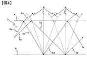
- FIG. 4 shows a part of the cross section of the light guide plate.
- Reference numeral 4 denotes an exit surface of the light guide plate
- 5 denotes a surface opposite to the exit surface of the light guide plate
- the medium on the exit surface side of the light guide plate is air as an example.
- the lights 6a and 7a that are reflected on the inside of the light guide plate in an oblique direction and are spread on the surface 6a has a small incident angle to the emission surface 4
- 7a has a large incident angle to the emission surface 4.
- 7d is the specular reflected light component
- 9 is the light in the front direction of the diffuse reflected light component.
- the light inside the light guide plate spreads on the surface while being reflected in an oblique direction, and part of the light 6c, 8 and 9 is emitted from the light guide plate to obtain light emitted on the surface.
- the light having a smaller incident angle on the emission surface 4 than the light 7a that is, light like 6a
- the light emitted obliquely to the outside of the light guide plate that is, 6c).
- the distribution of the light emitted from the light guide plate is emitted not only in the front direction but also in the oblique direction, so that the intensity of the light in the front direction decreases. ..
- the conventional method by arranging a diffusion sheet or a prism sheet on the exit surface side of the light guide plate, the direction of the oblique light emitted from the light guide plate is converted to the front direction. It corresponded.
- the diffusion sheet or the prism sheet because of the structure of the diffusion sheet or the prism sheet, it is not possible to collect all the light that enters at a shallow angle (light with a small incident angle), so even if the diffusion sheet or the prism sheet is used, it is emitted from the light guide plate. It was not possible to condense all the oblique light in the front direction.
- the present invention is intended to solve the above problems. That is, it is to provide a light source unit, a display device, and a film capable of further improving the light converging property and the front luminance as compared with the related art.
- the present invention has the following composition. That is, a light source unit having a light source and a film, wherein the light source has an emission band at a wavelength of 450 nm to 650 nm, and the film is incident from the light source at an angle of 0° with respect to a normal line of the film surface.
- the average transmittance of light having a wavelength of 450 nm to 650 nm is 70% or more, and the P-waves of light incident from the light source at angles of 20°, 40°, and 70° with respect to the normal to the film surface are
- the average reflectance (%) at a wavelength of 450 nm to 650 nm is Rp20, Rp40, and Rp70, the relationship of Rp20 ⁇ Rp40 ⁇ Rp70 is satisfied, and Rp70 is 30% or more, and the normal line of the film surface from the light source.
- the brightness of light incident at an angle of 0° is La (0°)
- the brightness of light incident at an angle of 70° with respect to the normal to the film surface is La (70°)
- the brightness of the light emitted from the film after entering the film at an angle of 0° with respect to the normal to the film surface is Lb (0°)
- a light source unit that satisfies the following expressions (1) and (2) when the brightness of light emitted from the film is Lb (70°).
- the present invention it is possible to obtain a light source unit, a display device, and a film capable of further improving the light converging property and the front luminance as compared with the conventional one.
- the schematic diagram which shows the angle dependence of the reflectance of the conventional transparent film of P wave and S wave The schematic diagram which shows the angle dependence of the reflectance of the P wave and S wave of the conventional reflective film.
- Schematic diagram illustrating a method for obtaining a conventional surface light source using a light guide plate Schematic diagram explaining the effect obtained when the film of the present invention is arranged on the emission surface side of the light guide plate.
- the present inventors provide a light source unit having a light source and a film, wherein the light source has an emission band at a wavelength of 450 nm to 650 nm, and the film is 0° with respect to a normal line of the film surface from the light source.
- Rp20 ⁇ Rp40 ⁇ Rp70 Satisfying the relationship of Rp20 ⁇ Rp40 ⁇ Rp70, where Rp20, Rp40, and Rp70 are the average reflectance (%) of the P-wave wavelength of 450 nm to 650 nm, and Rp70 is 30% or more.
- the luminance of light incident at an angle of 0° with respect to the surface normal is La (0°)
- the luminance of light incident at an angle of 70° with respect to the normal of the film surface is La (70°)
- the brightness of light emitted from the film at an angle of 0° with respect to the normal to the film surface after being incident on the film from the light source is Lb (0°), and is 70 to the normal to the film surface.
- an edge-type light guide is obtained by using a light source unit that satisfies the relationships of the following expressions (1) and (2). It has been found that light emitted from a light plate or a direct type diffusion sheet is condensed on the front surface to improve the front brightness. Lb(0°)/La(0°) ⁇ 0.8 (1) Lb(70°)/La(70°) ⁇ 1.0 (2).
- an electric field component is an electromagnetic wave whose P component is parallel to the incident surface (linearly polarized light that oscillates parallel to the incident surface), and an S wave is an electric field component is incident on the incident surface.
- FIG. 1 shows the conventional transparent film
- FIG. 2 shows the conventional reflective film
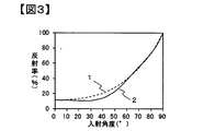
- FIG. 3 shows the film of the present invention.
- the reflectance of P-wave and S-wave having a wavelength of 550 nm when light enters each film from the air.
- the angle dependence of is shown.
- a wavelength of 550 nm is shown here as an example, the relationships shown in FIGS. 1 to 3 have an arbitrary wavelength.
- the conventional transparent film shows a tendency that the P-wave reflectance decreases with an increase in the incident angle, and then becomes 0% and then increases.
- the reflectance of the S wave increases as the incident angle increases.
- the reflectance of is increasing.
- the difference in the reflectance depending on the incident angle between the conventional reflective film and the film of the present invention is the difference in the refractive index in the direction parallel to the film surface of the two types of layers alternately laminated (in-plane refractive index Difference) and the difference in the refractive index in the direction perpendicular to the film surface (difference in the in-plane refractive index). That is, since the conventional reflective film is designed to reflect light by increasing the difference in the in-plane refractive index and the difference in the in-plane refractive index between the two types of layers that are alternately laminated, both the P wave and the S wave are incident. It has a constant reflectance even at an angle of 0 degree, and the reflectance of both P-wave and S-wave increases as the incident angle increases.
- FIG. 5 in which the film of the present invention is arranged on the light guide plate is shown as a schematic diagram for explaining the effect obtained when the film of the present invention is arranged on the emission surface side of the light guide plate. Since the light 6a has a small incident angle on the emission surface 4, most of the light 6a is conventionally emitted to the outside of the light guide plate as shown in FIG. 4, but the film of the present invention has a high reflectance for light in an oblique direction. Therefore, by arranging the film of the present invention on the exit surface side of the light guide plate, it is possible to return the light to the light guide plate by reflecting 6c, which allows the light emitted from the light guide plate to be collected on the front surface more than before. The brightness can be improved.
- the light 6b, 7b, 10b reflected by the film of the present invention and the exit surface of the light guide plate is reflected by the exit surface 5 of the light guide plate.
- 6d, 7d, and 10d are specular reflected light components
- 8, 9 and 11 are light in the front direction of the diffuse reflected light component. Since the film of the present invention has a high transmittance for the light in the front direction, the light 8, 9 and 11 can be transmitted without being reflected. Therefore, when the film of the present invention is used on the emission surface side of the light guide plate, the light emitted from the light guide plate in the front direction is 8, 9, and 11, so that the light emitted from the light guide plate is reduced compared to the conventional case. The light can be condensed on the front surface to improve the brightness.
- the structure of the light guide plate and the traveling direction of light inside the light guide plate described above are examples for explaining the effect of the film of the present invention, and the oblique light emitted from the light guide plate by using the present film. If the concept of reflecting the light back to the light guide plate and transmitting the light in the front direction emitted from the light guide plate is the same, even if the structure of the light guide plate or the traveling direction of the light inside the light guide plate is different from the above description, The function of converging the light emitted from the light plate to the front is exhibited.
- the surface 5 of the light guide plate on the side opposite to the emission surface is a flat surface, but it may be a rough surface or have an uneven shape.
- the film of the present invention does not necessarily have to be arranged right above the light guide plate, and one or more sheets such as a diffusion sheet may be arranged between the light guide plate and the film of the present invention.
- the film of the present invention when used not only for the light guide plate but also for the light source and the direct type surface light source device that emits light in the direction opposite to the light source, the film is emitted obliquely in the conventional manner due to the above effects. Since the light can be converted to the front direction, the emitted light can be focused on the front surface and the brightness can be improved.
- the light source unit of the present invention is a light source unit having a light source and a film, and it is necessary that the light source has an emission band at a wavelength of 450 nm to 650 nm.
- the emission band means an emission spectrum of a light source, a wavelength showing the maximum intensity of the emission spectrum is set as an emission peak wavelength of the light source, and an intensity of 5% or more of the emission intensity at the emission peak wavelength of the light source is shown. It represents the wavelength range of the lowest wavelength and the longest wavelength.
- the luminance of light incident from the light source at an angle of 0° with respect to the normal to the film surface is La (0°)
- the light incident at an angle of 70° with respect to the normal to the film surface is La (0°)
- the brightness of light emitted from the film at an angle of 0° with respect to the normal to the film surface after being incident on the film from the light source is Lb (0°)
- the film surface method is satisfied.
- Lb(0°)/La(0°) in the equation (1) means the brightness maintenance rate (or brightness improvement rate) in the front direction, and the higher the value, the brightness maintenance rate (or brightness improvement rate) in the front direction. ) Is high.
- (0°)/La(0°)>1 light stronger than light incident from the light source at an angle of 0° with respect to the normal to the film surface is 0° to the normal to the film surface. Indicates that the light is emitted at an angle.
- Lb(0°)/La(0°) is preferably more than 1.0, more preferably 1.1 or more, still more preferably 1.2 or more.
- Lb(70°)/La(70°) in the equation (2) means the transmittance of light in the oblique direction, and the smaller the value, the less the light in the oblique direction is transmitted.
- Lb(70°)/La(70°) is preferably smaller than 0.8, more preferably smaller than 0.7.
- the azimuth angle variation of Lb(70°)/La(70°) is 0.3 or less.
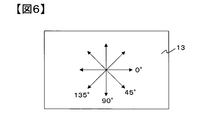
- the azimuth variation is Lb (70°) measured at each azimuth (0°, 45°, 90°, 135°) with the azimuth in the longitudinal direction of the light source unit being 0° as shown in FIG. /La (70°) represents the difference between the maximum value and the minimum value.
- a prism sheet which is a general light-condensing film, has unevenness in azimuth angle due to its light-collecting property, so multiple sheets are laminated to eliminate such unevenness, but it is still impossible to completely eliminate unevenness in azimuth angle. Can not.
- the film of the present invention has a small azimuth unevenness, a single sheet can have a light collecting effect.
- the azimuth variation of Lb(70°)/La(70°) is preferably 0.1 or less, more preferably 0.01 or less.
- the stretching include stretching so as to reduce the difference in orientation state between the longitudinal direction and the width direction of the film.
- a light guide plate unit in which the above-mentioned film is arranged on the exit surface side of the light guide plate, a light source unit having the light guide plate unit and a light source, a display device using the light source unit, and a plurality of light sources are provided.
- Examples thereof include an installed substrate, a light source unit in which the above-mentioned film is arranged on the emission surface side of the substrate, and a display device using the light source unit.
- the display device include a liquid crystal display device and an organic EL (Electro-Luminescence) display device.
- Examples of the configuration of the light source unit of the present invention include a light source unit configured to have a configuration such as a reflection film/light guide plate/diffusion sheet/prism sheet and installed to the side of the light guide plate to spread and emit light from a light source, and a plurality of light source units.
- An example is a substrate on which a light source is installed and a light source unit that irradiates light in a direction facing the light source with a structure such as a reflective film/diffuser/prism sheet on the exit surface side of the substrate.
- the reflective film may be a film that diffusely reflects or specularly reflects, and a film having particularly high diffuse reflectance is preferable, and a white reflective film is preferable.
- the number of the diffusion film or the prism sheet is one, and a configuration in which two or more sheets are used may be adopted.
- the light source include a white light source, a red, blue, and green monochromatic light source, and a combination of two types of these monochromatic light sources.
- the light emission band has a range of 450 nm to 650 nm, and the light emission method is an LED (Light Emitting Diode), Examples include CCFL (Cold Cathode Fluorescent Lamp) and organic EL.
- the film of the present invention is preferably used by arranging it on the emission surface side of the light guide plate if it is a light source unit using a light guide plate.
- a light source and a light source unit that emits light in a direction facing the light source are preferably used by being disposed on the emission surface side of the diffusion plate. Further, it is preferable not only to install the device with an air gap, but also to bond it to another member with an adhesive agent or an adhesive agent.
- An example of the configuration of a display device using the light source unit of the present invention has a configuration in which a diffusion sheet/prism sheet/polarization reflection film is arranged in this order, and the film of the present invention is provided between the diffusion sheet and the polarization reflection film.
- An example of the display device is a display device. With such a configuration, it is possible to condense in the front direction the emitted light that has been erased by the diffusion sheet but has strong oblique light. Further, even if a polarizing plate or a liquid crystal cell is installed on the viewing side of the polarized reflection film, it is possible to suppress the occurrence of rainbow unevenness in which the display screen becomes iridescent.
- a display device having a structure in which a reflection film/light guide plate/diffusion sheet/prism sheet/polarization reflection film is arranged in that order, and the film of the present invention is arranged between the diffusion sheet and the polarization reflection film
- a display device having a structure in which a reflection film/light source/diffusion sheet/prism sheet/polarization reflection film is arranged in that order, and the film of the present invention is arranged between the diffusion sheet and the polarization reflection film. It is mentioned as an aspect.
- An example of the configuration of the display device of the present invention is a display device including an infrared sensor.
- a display device provided with an infrared sensor can have an authentication function for identifying a user by authenticating a fingerprint, a face, an iris of an eye, or the like with infrared rays.
- an infrared sensor can be provided with a function of operating the display device by detecting movements of the user's fingers, hands, eyes, and the like. It is preferable that the display device member between the infrared sensor that receives infrared light and the object to be discriminated has high infrared parallel light transmittance.
- the film of the present invention preferably has a maximum parallel light transmittance of 50% or more, and more preferably 70%, of light incident at an angle of 0° with respect to the normal line of the film surface at a wavelength of 800 nm to 1600 nm.
- the above is more preferably 80% or more, and particularly preferably 85% or more.
- the emission/reception wavelength of the infrared sensor is in the range of 800 nm to 1600 nm, and examples of peak wavelengths include 850 nm, 905 nm, 940 nm, 950 nm, 1200 nm, 1550 nm.
- the structure of the light source unit used for the display device having the infrared sensor is a light source that spreads the light of the light source installed beside the light guide plate on the surface and emits it with a structure such as a reflection film/light guide plate/diffusion sheet/film of the present invention.
- Examples thereof include a unit and a substrate on which a plurality of light sources are installed, and a light source unit that irradiates light in a direction facing the light source with a configuration such as a reflection film/diffusion plate/film of the present invention on the emission surface side of the substrate.
- the display device member between the infrared sensor and the object to be discriminated has a high infrared parallel light transmittance and an infrared scattering rate (infrared haze). Is preferably low.
- the prism sheet which is shaped like a triangle (prism) on a flat substrate, exerts its condensing effect not only on visible light but also on infrared light. Further, when light (visible light/infrared light) is incident from the surface of the base material, a light-collecting effect is exhibited, but light (visible light/infrared light) incident from the prism surface is diffused. Further, it has a high reflectance for light having an incident angle of 0° which is incident from the surface of the base material. Therefore, when the infrared information detected by the infrared sensor passes through the prism sheet, the infrared information is disturbed due to phenomena such as light collection, diffusion, and reflection. When the infrared information is disturbed, there is a problem that the detection accuracy of the infrared sensor decreases. When such a phenomenon occurs, it is not preferable to use the prism sheet.
- the film of the present invention in the film of the present invention, light incident at an angle of 0° with respect to the normal to the film surface does not disturb infrared information because not only visible light transmittance but also infrared parallel light transmittance is high. Therefore, when the film of the present invention is used in a display device having an infrared sensor, it is possible to achieve both improved brightness and improved infrared detection accuracy.
- the display device of the present invention is preferably provided with a viewing angle control layer.
- the viewing angle control layer is preferably arranged in the display device further on the emission surface side than the position where the film of the present invention is arranged.
- An example of the viewing angle control layer is a liquid crystal layer, in which liquid crystal molecules in the liquid crystal layer change in orientation from an oblique direction to a horizontal direction or are oriented from a horizontal direction to an oblique direction in response to electric current to the liquid crystal molecules. It is preferable that the liquid crystal molecule has a characteristic of changing.
- the viewing angle is controlled to the front when the alignment of the liquid crystal layer is in the oblique direction and to the wide angle when the alignment of the liquid crystal layer is in the horizontal direction.
- the film of the present invention comprises three or more layers in which a layer (A layer) made of the thermoplastic resin A and a layer (B layer) made of a thermoplastic resin B different from the thermoplastic resin A are alternately laminated. It is preferable that the multilayer laminated film is
- the term “different” of the thermoplastic resin B different from the thermoplastic resin A as used herein means that any of crystalline/amorphous, optical property and thermal property is different.
- the difference in optical properties means that the refractive index differs by 0.01 or more, and the difference in thermal properties means that the melting point or the glass transition temperature differs by 1° C. or more.
- thermoplastic resins when one resin has a melting point and the other resin does not have a melting point, or when one resin has a crystallization temperature and the other resin has a crystallization temperature. If not, it means having different thermal properties.
- thermoplastic resins having different properties it is possible to give the film a function which cannot be achieved by a single layer film of each thermoplastic resin.
- thermoplastic resin used in the film of the present invention examples include polyolefins such as polyethylene, polypropylene, and poly(4-methylpentene-1), and examples of cycloolefins include ring-opening metathesis polymerization, addition polymerization, and the like of norbornenes.
- Aliphatic polyolefins that are addition copolymers with olefins, biodegradable polymers such as polylactic acid and polybutylsuccinate, polyamides such as nylon 6, nylon 11, nylon 12, nylon 66, aramids, polymethylmethacrylate, Polyvinyl chloride, polyvinylidene chloride, polyvinyl alcohol, polyvinyl butyral, ethylene vinyl acetate copolymer, polyacetal, polyglycolic acid, polystyrene, styrene copolymer polymethylmethacrylate, polycarbonate, polypropylene terephthalate, polyethylene terephthalate, polybutylene terephthalate, polyethylene-2 Polyester such as 6-naphthalate, polyether sulfone, polyether ether ketone, modified polyphenylene ether, polyphenylene sulfide, polyetherimide, polyimide, polyarylate, tetrafluoroethylene resin, trifluoroethylene resin
- polyester from the viewpoints of strength, heat resistance and transparency, it is particularly preferable to use polyester, and as the polyester, polymerization from a monomer having aromatic dicarboxylic acid or aliphatic dicarboxylic acid and diol as main constituent components
- the polyester obtained by is preferable.
- aromatic dicarboxylic acid for example, terephthalic acid, isophthalic acid, phthalic acid, 1,4-naphthalenedicarboxylic acid, 1,5-naphthalenedicarboxylic acid, 2,6-naphthalenedicarboxylic acid, 4,4′-diphenyl
- aromatic dicarboxylic acid for example, terephthalic acid, isophthalic acid, phthalic acid, 1,4-naphthalenedicarboxylic acid, 1,5-naphthalenedicarboxylic acid, 2,6-naphthalenedicarboxylic acid, 4,4′-diphenyl
- dicarboxylic acid 4,4'-diphenyl ether dicarboxylic acid
- 4,4'-diphenyl sulfone dicarboxylic acid 4,4'-diphenyl sulfone dicarboxylic acid.
- aliphatic dicarboxylic acid examples include adipic acid, suberic acid, sebacic acid, dimer acid, dodecanedioic acid, cyclohexanedicarboxylic acid and ester derivatives thereof. Of these, terephthalic acid and 2,6-naphthalenedicarboxylic acid are preferred. These acid components may be used alone or in combination of two or more, and further, an oxy acid such as hydroxybenzoic acid may be partially copolymerized.
- diol component examples include ethylene glycol, 1,2-propanediol, 1,3-propanediol, neopentyl glycol, 1,3-butanediol, 1,4-butanediol and 1,5-pentanediol. 1,6-hexanediol, 1,2-cyclohexanedimethanol, 1,3-cyclohexanedimethanol, 1,4-cyclohexanedimethanol, diethylene glycol, triethylene glycol, polyalkylene glycol, 2,2-bis(4- Hydroxyethoxyphenyl)propane, isosorbate, spiroglycol and the like can be mentioned. Among them, ethylene glycol is preferably used. These diol components may be used alone or in combination of two or more.
- polyesters polyethylene terephthalate and its copolymers, polyethylene naphthalate and its copolymers, polybutylene terephthalate and its copolymers, polybutylene naphthalate and its copolymers, and further polyhexamethylene terephthalate and its copolymers. It is preferred to use polymers and polyesters selected from polyhexamethylene naphthalate and copolymers thereof.
- thermoplastic resins having different properties used is that the absolute value of the difference in the glass transition temperature of each thermoplastic resin is 20° C. or less. Preferably. This is because when the absolute value of the difference in glass transition temperature is larger than 20° C., drawing defects are likely to occur during production of the multilayer laminated film.
- thermoplastic resins having different properties to be used is that the absolute value of the difference between SP values (also referred to as solubility parameters) of the respective thermoplastic resins is It is particularly preferably 1.0 or less.
- the absolute value of the difference in SP value is 1.0 or less, delamination becomes difficult to occur.
- the polymers having different properties are preferably composed of combinations providing the same basic skeleton.
- the basic skeleton referred to here is a repeating unit that constitutes a resin.
- the other thermoplastic resin is used from the viewpoint of easily realizing a highly accurate laminated structure.
- the resin preferably contains ethylene terephthalate, which has the same basic skeleton as polyethylene terephthalate.
- the polyester resins having different optical properties are resins containing the same basic skeleton, the stacking accuracy is high and further delamination at the stacking interface is less likely to occur.
- Copolymers are desirable in order to have the same basic skeleton and different properties. That is, for example, when one resin is polyethylene terephthalate, the other resin is a resin composed of an ethylene terephthalate unit and another repeating unit having an ester bond.
- the ratio of other repeating units (sometimes referred to as the amount of copolymerization) is preferably 5 mol% or more from the viewpoint of obtaining different properties, while the difference in the adhesiveness between layers and the difference in heat flow characteristics are small. 90 mol% or less is preferable because it is excellent in thickness accuracy and thickness uniformity. More preferably, it is 10 mol% or more and 80 mol% or less.
- the A layer and the B layer are each made of a blend or alloy of plural kinds of thermoplastic resins.
- thermoplastic resins By blending or alloying a plurality of types of thermoplastic resins, it is possible to obtain performance that cannot be obtained with one type of thermoplastic resin.
- the thermoplastic resin A and/or the thermoplastic resin B is preferably polyester, and the thermoplastic resin A contains polyethylene terephthalate as a main component and the thermoplastic resin.
- B comprises terephthalic acid as a dicarboxylic acid component and ethylene glycol as a diol component, and further, at least one of naphthalenedicarboxylic acid, cyclohexanedicarboxylic acid as a dicarboxylic acid component, cyclohexanedimethanol, spiroglycol, and isosorbide as a diol component.
- thermoplastic resin A means that it accounts for 70% by weight or more of the entire resin constituting the layer A.
- main component of the thermoplastic resin B means that it accounts for 35% by weight or more of the whole resin constituting the B layer.
- the film of the present invention has an average transmittance of 70% or more at a wavelength of 450 nm to 650 nm of light when incident at an angle of 0° with respect to the normal to the film surface, and is 20° with respect to the normal to the film surface.
- Rp20 ⁇ Rp40 ⁇ Rp70 where Rp20, Rp40, and Rp70 are the average reflectances (%) of wavelengths 450 nm to 650 nm of the respective P-waves when incident at 40° and 70°.
- Rp70 is 30% or more.
- the film of the present invention is a multilayer laminated film in which A layers and B layers are alternately laminated, and the difference in the in-plane refractive index between the A layer and the B layer is small and the difference in the in-plane refractive index between the A layer and the B layer. Is preferably large.
- the difference in in-plane refractive index between the A layer and the B layer is preferably 0.03 or less, more preferably 0.02 or less, and further preferably 0.01 or less.
- the difference in the in-plane refractive index between the A layer and the B layer is preferably more than 0.03, more preferably 0.06 or more, still more preferably 0.09 or more.
- the resin constituting the A layer and the B layer is a thermoplastic resin and one layer (the A layer) is constituted.
- the thermoplastic resin containing crystalline polyester as a main component, and the thermoplastic resin forming the other layer (B layer) has a melting point of 20° C. or more lower than that of the amorphous polyester or the polyester forming the A layer.
- the difference between the in-plane refractive indices of the A layer and the B layer is 0.04 or less, and the difference between the glass transition temperatures of the resins forming the A layer and the B layer is 20° C. or less. Can be mentioned.
- thermoplastic resin In order to reduce the in-plane refractive index difference between the A layer and the B layer and increase the in-plane refractive index difference, one thermoplastic resin is strongly oriented in a direction parallel to the film surface (parallel to the film surface). While the refractive index in the direction perpendicular to the film surface is large and the refractive index in the direction perpendicular to the film surface is small), the other thermoplastic resin maintains the isotropic property (direction parallel to the film surface and perpendicular to the film surface). It is important that the refractive index is the same).
- thermoplastic resin forming the layer A is a crystalline polyester, it can be strongly oriented in a direction parallel to the film surface, and the thermoplastic resin forming the layer B is an amorphous polyester or A
- the crystalline polyester having a melting point lower than that of the layer by 20° C. or more can be isotropic.
- the A layer is oriented and crystallized by using a crystalline resin, and the B layer is made to be amorphous.
- the refractive index is isotropic and the refractive index is high.
- the refractive index in the direction parallel to the film surface (in-plane direction) increases, and the refractive index in the direction perpendicular to the film surface (perpendicular direction) decreases.
- thermoplastic resin used in the A layer has a low aromatic content orientation.
- a crystalline resin may be used, and as the amorphous resin used for the layer B, an amorphous resin having a high aromatic content or a crystalline resin having a melting point of 20° C. or more lower than that of the orientation/crystalline resin may be laminated. preferable.
- the glass transition temperature of the orientation/crystalline resin is low, and the amorphous resin or the orientation/ The glass transition temperature of a crystalline resin having a melting point lower than that of the crystalline resin by 20° C. or more tends to be high.
- a film having desired reflection performance may not be obtained. Therefore, by setting the difference in glass transition temperature of the thermoplastic resin constituting the multilayer stack to 20° C. or less, it becomes easy to sufficiently orient the resin to be oriented and to set Rp to 30% or more.
- an oriented/crystalline thermoplastic resin and an amorphous resin, or a crystalline resin having a melting point lower than that of the oriented/crystalline resin by 20° C. or more is formed at a film stretching temperature at which orientation/crystallization is accelerated. Therefore, the transparency in the direction perpendicular to the film surface and the excellent reflection performance in the oblique direction to the film surface can both be easily achieved.
- the difference between the glass transition temperatures of the A layer and the B layer is more preferably 15° C. or higher, and even more preferably 5° C. or lower. As the difference in glass transition temperature becomes smaller, it becomes easier to adjust the film stretching conditions, and it becomes easier to improve the optical performance.
- the thermoplastic resin constituting the layer B contains a structure derived from alkylene glycol having a number average molecular weight of 200 or more.
- the thermoplastic resin constituting the layer B contains a structure derived from alkylene glycol having a number average molecular weight of 200 or more.
- the in-plane average refractive index of each layer constituting the laminated film can be increased and the glass transition temperature can be easily lowered.
- alkylene glycol examples include polyethylene glycol, polytrimethylene glycol, polytetramethylene glycol and the like.
- the molecular weight of the alkylene glycol is more preferably 200 or more, further preferably 300 or more and 2000 or less.
- the molecular weight of the alkylene glycol is less than 200, alkylene glycol is not sufficiently incorporated into the polymer due to its high volatility during the synthesis of the thermoplastic resin, and as a result, the effect of lowering the glass transition temperature is sufficient. May not be obtained.
- the molecular weight of the alkylene glycol is larger than 2000, the reactivity may decrease during the production of the thermoplastic resin, and the film may not be suitable for production.
- the thermoplastic resin constituting the layer B contains a structure derived from two or more kinds of aromatic dicarboxylic acids and two or more kinds of alkyl diols, and an alkylene glycol having a number average molecular weight of 200 or more. It is preferable to include a structure derived from By including such a structure in the B layer, a high refractive index comparable to the in-plane refractive index of the A layer, which is an oriented crystalline resin, is realized in an amorphous state, and it is co-stretched with a crystalline thermoplastic resin. It is necessary to indicate possible glass transition temperatures. It is difficult to satisfy all these requirements with a single dicarboxylic acid or alkylene diol.
- the film of the present invention preferably has a P-wave reflectance of 30% or more, and more preferably 50%, in the wavelength range of 400 nm to 700 nm when incident at an angle of 70° with respect to the normal to the film surface. Or more, and more preferably 70% or more.
- the film of the present invention has a property that the reflection wavelength band shifts to the lower wavelength side as the incident angle increases.
- the reflectance of P waves in the wavelength range of 400 nm to 700 nm when incident at an angle of 70° with respect to the normal to the film surface is 30% or more, so that even at an incident angle of 70° or more. It can have a sufficient reflectance in the wavelength range of 450 nm to 650 nm which is the emission band of the light source.
- the average reflectance Rp70 of the P-wave wavelength 450 nm to 650 nm when incident at an angle of 70° with respect to the normal to the film surface, and the average reflectance Rp70 at an angle of 70° with respect to the normal to the film surface is preferably 1 or more, more preferably 1.2 or more, further preferably 1.5 or more. Since the reflectance of P-wave when it is incident at an angle of 70° is high, the effect of condensing and improving the brightness when using the film of the present invention is high.
- the average reflectance Rp40 of the P-wave wavelength of 450 nm to 650 nm when incident at an angle of 40° with respect to the normal to the film surface, and the average reflectance Rp40 at an angle of 40° with respect to the normal to the film surface is preferably 1 or more, more preferably 1.2 or more, and further preferably 1.5 or more.
- the method for adjusting the reflectance in the desired wavelength range is as follows: the difference in the in-plane refractive index between the A layer and the B layer, the number of layers, the layer thickness distribution, and the film forming conditions (for example, draw ratio, draw speed, draw temperature, heat treatment temperature, heat treatment time). ) Adjustment and the like.
- the A layer and the B layer it is preferable that the A layer is made of a crystalline thermoplastic resin and the B layer is made of a resin containing an amorphous thermoplastic resin as a main component.
- the resin containing an amorphous thermoplastic resin as a main component means that the weight ratio of the amorphous thermoplastic resin is 70% or more.
- the number of laminated layers is preferably 101 layers or more, more preferably 401 layers or more, and further preferably 601.
- the number of layers is at least 5,000, and the upper limit is about 5,000 from the viewpoint of increasing the size of the laminating apparatus.
- the optical thicknesses of the adjacent A layer and B layer satisfy the following expression (A).
- ⁇ is the reflection wavelength
- n A is the in-plane refractive index of the A layer
- d A is the thickness of the A layer
- n B is the in-plane refractive index of the B layer
- d B is the thickness of the B layer.
- the layer thickness distribution is a constant layer thickness distribution from one side of the film to the opposite side, a layer thickness distribution that increases or decreases from one side of the film to the opposite side, or from one side of the film.
- a layer thickness distribution that decreases after the layer thickness increases toward the film center, a layer thickness distribution that increases after the layer thickness decreases from one side of the film toward the film center, and the like are preferable.
- the layer thickness distribution can be changed in a linear manner, a geometrical ratio, a difference sequence, or continuously varying, or about 10 to 50 layers have almost the same layer thickness, and the layer thickness is stepwise. Those that change are preferred.
- a layer having a layer thickness of 3 ⁇ m or more can be preferably provided as a protective layer on both surface layers of the multilayer laminated film.
- the thickness of the protective layer is preferably 5 ⁇ m or more, more preferably 10 ⁇ m or more. By increasing the thickness of the protective layer, it is possible to suppress flow marks during film formation, suppress the deformation of the thin film layer in the multilayer laminated film after laminating with another film or a molded product and the laminating process, and press resistance. Can be mentioned.
- the thickness of the multilayer laminated film is not particularly limited, but is preferably 20 ⁇ m to 300 ⁇ m, for example. If it is less than 20 ⁇ m, the film may have a poor rigidity and may be poor in handleability. On the other hand, when it exceeds 300 ⁇ m, the film may be too stiff and the moldability may be deteriorated.
- the film of the present invention needs to have an average transmittance of 70% or more at a wavelength of light of 450 nm to 650 nm when incident at an angle of 0° with respect to the normal to the film surface. It is more preferably 85% or more, still more preferably 90% or more. It is preferable that the transmittance of light incident perpendicularly to the film surface is higher, because the light-collecting effect when the film of the present invention is used is higher. As a method of increasing the transmittance of light incident perpendicularly to the film surface, the difference in the in-plane refractive index between the A layer and the B layer is reduced, and a primer layer, a hard coat layer, or an antireflection layer is provided on the film surface. Is preferred. By providing a layer having a refractive index lower than that of the resin on the film surface, it is possible to increase the transmittance of light that is vertically incident on the film surface.
- the film of the present invention has a primer layer, a hard coat layer, an abrasion resistant layer, an anti-scratch layer, an antireflection layer, a color correction layer, an ultraviolet absorbing layer, a light stabilizing layer (HALS), a heat ray absorbing layer on the surface of the film. It may have a functional layer such as a printing layer, a gas barrier layer and an adhesive layer. These layers may be one layer or multiple layers, and one layer may have a plurality of functions. Further, the multilayer laminated film may contain additives such as an ultraviolet absorber, a light stabilizer (HALS), a heat ray absorber, a crystal nucleating agent and a plasticizer.
- HALS light stabilizer
- the film of the present invention preferably has a retardation of 2000 nm or less.
- the resin is selected so that the difference in the refractive index in either direction becomes small, they are orthogonal to each other.
- the refractive index in the direction becomes large. As a result, it may be difficult to achieve transparency in the direction perpendicular to the film surface.
- the retardation which is a parameter relating to the anisotropy of the alignment state
- the phase difference is preferably 1000 nm or less, more preferably 500 nm or less.
- a laminated structure having three or more layers can be produced by the following method.
- a thermoplastic resin is supplied from two extruders, an extruder A corresponding to the A layer and an extruder B corresponding to the B layer, and the polymer from each flow path is a multi-manifold type feed block which is a known laminating device.
- a method of using a square mixer or a comb-type feed block alone is used to laminate three or more layers.
- melt is melt-extruded into a sheet using a T-type die or the like, and then cooled and solidified on a casting drum to obtain an unstretched multilayer laminated film.
- the methods described in JP2007-307893A, JP46919910A, and JP48164419A are preferable.
- the unstretched multilayer laminated film is stretched and heat-treated.
- a stretching method it is preferable to perform biaxial stretching by a known sequential biaxial stretching method or a simultaneous biaxial stretching method.
- the stretching temperature is preferably in the range of not less than the glass transition temperature of the unstretched multilayer laminated film to not more than the glass transition temperature +80°C.
- the stretching ratio is preferably in the range of 2 to 8 times in the longitudinal direction and in the width direction, more preferably in the range of 3 to 6 times, and it is preferable to reduce the difference in the stretching ratio between the longitudinal direction and the width direction.
- the stretching in the longitudinal direction is preferably performed by utilizing the speed change between the rolls of the longitudinal stretching machine.
- the stretching in the width direction uses a known tenter method. That is, the film is conveyed while being gripped by both ends of the film, and is stretched in the width direction by widening the clip interval between both ends of the film. In addition, it is also preferable that the stretching in the tenter is simultaneous
- the unstretched film cast on the cooling roll is guided to a simultaneous biaxial tenter, conveyed while gripping both ends of the film with clips, and stretched simultaneously and/or stepwise in the longitudinal direction and the width direction. Stretching in the longitudinal direction is achieved by increasing the distance between the clips of the tenter, and in the width direction by increasing the distance between the rails on which the clips run. It is preferable that the tenter clip to be stretched and heat treated in the present invention is driven by a linear motor system. In addition, there are a pantograph method, a screw method, and the like. Among them, the linear motor method is excellent in that the stretching ratio can be freely changed because each clip has a high degree of freedom.
- the heat treatment temperature is preferably in the range of the stretching temperature or higher to the melting point of the thermoplastic resin of the layer A-10°C or less, and it is also preferable to carry out a cooling step in the range of heat treatment temperature-30°C or less after the heat treatment.
- a cooling step in the range of heat treatment temperature-30°C or less after the heat treatment.
- the relaxation rate is preferably in the range of 1% to 10%, more preferably in the range of 1% to 5%.
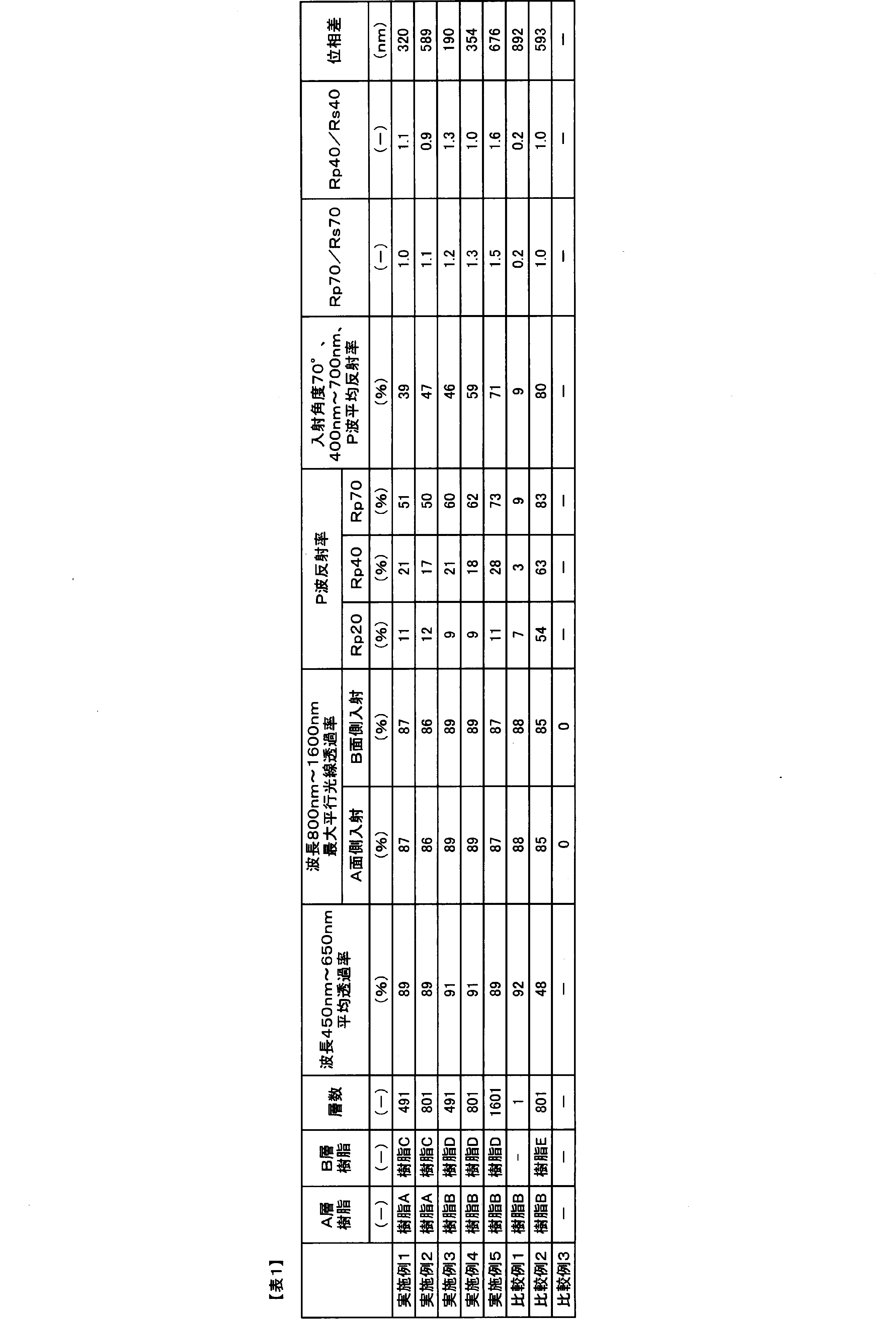
- the film of the present invention will be described with reference to specific examples. Even when a thermoplastic resin other than the thermoplastic resins specifically exemplified below is used, the film of the present invention can be obtained in the same manner by considering the description of the present specification including the following examples. .. [Measurement method of physical properties and evaluation method of effect] The method of evaluating physical properties and the method of evaluating effects are as follows.
- Main orientation axis direction The sample size was 10 cm ⁇ 10 cm, and the sample was cut out at the center of the film width direction.
- the main orientation axis direction was determined using a molecular orientation meter MOA-2001 manufactured by KS Systems Co., Ltd. (currently Oji Scientific Instruments Co., Ltd.).
- Rp20, Rp40, and Rp70 are obtained as average reflectances of P waves in the wavelength range of 450 nm to 650 nm at incident angles of 20°, 40°, and 70°, and Rs20, Rs40 as average reflectances of S waves, Rs70 was calculated, and Rp40/Rs40 and Rp70/Rs70 were calculated. Further, the inclination directions of 20°, 40°, and 70° were the directions along the main alignment axis of the film.
- Refractive index A resin pellet vacuum dried at 70° C. for 48 hours was melted at 280° C., pressed with a pressing machine, and then rapidly cooled to form a sheet having a thickness of 500 ⁇ m.
- the refractive index of the prepared sheet was measured using an Abbe refractometer (NAR-4T) manufactured by Atago Co. and a NaD ray lamp.
- Phase difference A phase difference measuring device (KOBRA-21ADH) manufactured by Oji Scientific Instruments was used. A film sample cut out with a size of 3.5 cm ⁇ 3.5 cm was placed in the apparatus, and the retardation at a wavelength of 590 nm at an incident angle of 0° was measured.
- Backlight 1 32-inch white LED edge type backlight, light emission band of 425 nm to 652 nm
- Backlight 2 43-inch white LED direct backlight, light emission band of 418 nm to 658 nm
- the brightness was measured by using BM-7 manufactured by Topcon and an angle variable unit to measure the light receiving angles of +70°, ⁇ 70°, and 0°, and the brightness of 70° was an average value of +70° and ⁇ 70°.
- the azimuth angle inclined to the light receiving angle of 70° is the longitudinal direction of the backlight, and the luminances La (0°) and La (70°) of the incident light at angles of 0° and 70° with respect to the normal to the film surface of the present invention.
- the luminance of light emitted at angles of 0° and 70° with respect to the normal line of the film surface of the present invention from Lb(0°) and Lb(70°) to the formulas (1) and (2). was calculated.
- a coating liquid for forming a laminated film composed of resin)/(polyester resin having a glass transition temperature of 82° C.)/silica particles having an average particle diameter of 100 nm was applied. After that, the both ends are guided to a tenter which holds them with clips, laterally stretched 3.5 times at 100°C, then heat-treated at 210°C and relaxed in the width direction by 5%, cooled at 100°C, and then a multilayer with a thickness of 60 ⁇ m. A laminated film was obtained. Table 1 shows the physical properties of the obtained film.
- a coating liquid for forming a laminated film composed of resin)/(polyester resin having a glass transition temperature of 82° C.)/silica particles having an average particle diameter of 100 nm was applied. After that, the both ends are guided to a tenter that holds them with clips, laterally stretched 3.5 times at 100°C, then heat-treated at 210°C and relaxed in the width direction by 5%, and cooled at 100°C. A laminated film was obtained. Table 1 shows the physical properties of the obtained film.
- Example 5 The two multilayer laminated films prepared in Example 4 were laminated with a laminator using a 25 ⁇ m thick acrylic optical adhesive. Table 1 shows the physical properties of the produced film.
- Resin B was used as the thermoplastic resin. It is melted at 280°C in an extruder, passed through 5 FSS type leaf disk filters, then fed to a T-die, shaped into a sheet, and then subjected to electrostatic application voltage of 8 kV with a wire, while being subjected to surface temperature. An unstretched film was obtained by rapid cooling and solidification on a casting drum kept at 25°C. This unstretched film was longitudinally stretched at 90° C. and a draw ratio of 3.3 times, and both surfaces of the film were subjected to corona discharge treatment in air, and the treated surfaces on both sides of the film (polyester having a glass transition temperature of 18° C.
- a coating liquid for forming a laminated film composed of resin)/(polyester resin having a glass transition temperature of 82° C.)/silica particles having an average particle diameter of 100 nm was applied. After that, the both ends are guided to a tenter which holds them with clips, and transversely stretched 3.5 times at 100° C., then heat treatment at 210° C. and 5% width direction relaxation are performed, and after cooling at 100° C., a film having a thickness of 50 ⁇ m Got Table 1 shows the physical properties of the obtained film.
- Example 2 A multilayer laminated film having a thickness of 110 ⁇ m was obtained in the same manner as in Example 4 except that the resin E was used as the thermoplastic resin forming the layer B. Table 1 shows the physical properties of the obtained film.
- Table 2 shows the backlight configuration, the position where the film is arranged, and the measured front luminance (in the table, the front relative luminance represents the front luminance when the luminance of the conventional configuration without a film is 100%). .. As shown in Table 2, it can be seen that the light source unit using the film of the present invention has improved front brightness as compared with the conventional backlight configuration and the configuration using the conventional film.
- the brightness was measured using a 43-inch white LED direct type backlight (backlight 2).
- the light source is a conventional direct type backlight (a light source is installed on a substrate, and a white reflective film in which the light source position is hollowed out is installed on the substrate) (1)
- the films of Example 1, Example 4, Example 5, Comparative Example 1, and Comparative Example 2 are arranged at the positions shown in Table 3, respectively, the front luminance of the entire light source unit, the luminance incident on the film, and the emission from the film.
- Table 3 shows the backlight configuration, the position where the film is arranged, and the measured front luminance (in the table, the front relative luminance represents the front luminance when the luminance of the conventional configuration without the film is 100%). ..
- the present invention relates to a light source unit, a display device, and a film with front luminance further improved than before.
Landscapes
- Physics & Mathematics (AREA)
- General Physics & Mathematics (AREA)
- Optics & Photonics (AREA)
- Nonlinear Science (AREA)
- Crystallography & Structural Chemistry (AREA)
- Mathematical Physics (AREA)
- Chemical & Material Sciences (AREA)
- Engineering & Computer Science (AREA)
- Microelectronics & Electronic Packaging (AREA)
- General Engineering & Computer Science (AREA)
- Planar Illumination Modules (AREA)
- Optical Elements Other Than Lenses (AREA)
- Liquid Crystal (AREA)
- Polarising Elements (AREA)
Abstract
Description
Lb(0°)/La(0°)≧0.8 ・・・(1)
Lb(70°)/La(70°)<1.0 ・・・(2)
Lb(0°)/La(0°)≧0.8 ・・・(1)
Lb(70°)/La(70°)<1.0 ・・・(2)。
Lb(0°)/La(0°)≧0.8 ・・・(1)
Lb(70°)/La(70°)<1.0 ・・・(2)。

[物性の測定方法ならびに効果の評価方法]
物性値の評価方法ならびに効果の評価方法は次の通りである。
サンプルサイズを10cm×10cmとし、フィルム幅方向中央において、サンプルを切り出した。KSシステムズ(株)製(現王子計測機器(株))の分子配向計MOA-2001を用いて、主配向軸方向を求めた。
日立製作所(株)製 分光光度計(U-4100 Spectrophotomater)の標準構成(固体測定システム)にて、入射角度φ=0°における波長450~1600nmの透過率を1nm刻みで測定し、450nm~650nmの平均透過率と波長800nm~1600nmの最小透過率を求めた。測定条件:スリットは2nm(可視)/自動制御(赤外)とし、ゲインは2と設定し、走査速度を600nm/分とした。
日立製作所(株)製 分光光度計(U-4100 Spectrophotomater)に付属の角度可変反射ユニットとグランテーラ偏光子を取り付け、入射角度φ=0°における波長800nm~1600nmの範囲において1nm刻みで透過率を測定し、その最大値を求めた。この測定におけるサンプルに対する光の入射面は、両方の面(便宜上、両方の面をそれぞれA面、B面と呼ぶ)それぞれで行った。サンプルと積分球入口との距離は14cmであった。
日立製作所(株)製 分光光度計(U-4100 Spectrophotomater)に付属の角度可変反射ユニットとグランテーラ偏光子を取り付け、入射角度φ=20°、40°、70°における波長400~700nmの範囲において1nm刻みでP波とS波それぞれの反射率を測定した。得られた反射率から入射角度20°、40°、70°における波長450nm~650nmの範囲におけるP波の平均反射率としてRp20、Rp40、Rp70を求め、S波の平均反射率としてRs20、Rs40、Rs70を求め、さらに、Rp40/Rs40、Rp70/Rs70を算出した。また、20°、40°、70°の傾斜方向はフィルムの主配向軸に沿う方向とした。
樹脂ペレットを電子天秤で5mg計量し、アルミパッキンで挟み込みセイコーインスツルメント社(株)ロボットDSC-RDC220示差走査熱量計を用いて、JIS-K-7122(1987年)に従い、25℃から300℃まで20℃/分で昇温して測定を行った。データ解析は同社製ディスクセッションSSC/5200を用いた。得られたDSCデータからガラス転移点温度(Tg)、融点(Tm)を求めた。
70℃48時間、真空乾燥した樹脂ペレットを280℃で溶融後、プレス機を用いてプレスし、その後急冷することで、厚み500μmのシートを作成した。作成したシートをアタゴ社製 アッベ屈折率計(NAR-4T)とNaD線ランプを用いて屈折率を測定した。
溶媒としてオルトクロロフェノールを用いて、温度100℃で20分溶解した後、温度25℃でオストワルド粘度計を用いて測定した溶液粘度から算出した。
王子計測機器(株)製 位相差測定装置(KOBRA-21ADH)を用いた。3.5cm×3.5cmで切り出したフィルムサンプルを装置に設置し、入射角0°における波長590nmのレタデーションを測定した。
浜松フォトニクス製ミニ分光光度器(C10083MMD)にNA0.22の光ファイ
バーを取り付け、光源の光を計測した。得られた発光スペクトルの350nm~800nmの波長範囲について、最大強度を示す波長を光源の発光ピーク波長とし、光源の発光ピーク波長での発光強度の5%以上の強度を示す最も低波長の波長と最も長波長の波長の波長範囲を光源の発光帯域とした。
光源ユニットには以下の2つのバックライトを用いた。
バックライト1:32インチ白色LEDエッジ型バックライト、光源の発光帯域425nm~652nm
バックライト2:43インチ白色LED直下型バックライト、光源の発光帯域418nm~658nm
輝度の測定はトプコン製BM-7と角度可変ユニットを用いて受光角度+70°、-70°、0°の輝度を測定し、70°の輝度は+70°と-70°の平均値とした。受光角度70°に傾斜させる方位角はバックライトの長手方向とし本発明のフィルム面の法線に対して0°、70°の角度で入射する光の輝度La(0°)、La(70°)と、本発明のフィルム面の法線に対して0°、70°の角度で出射される光の輝度をLb(0°)、Lb(70°)から式(1)、式(2)を算出した。さらに、バックライトの長手方向の方位角を0°とし、右回りに45°、90°、135°それぞれの方位角で70°に傾斜させて測定した輝度Lb(70°)/La(70°)の最大値と最小値の差を算出した。
樹脂A:IV=0.67のポリエチレンテレフタレートの共重合体(イソフタル酸成分を酸成分全体に対して10mol%共重合したポリエチレンテレフタレート)、屈折率1.57、Tg75℃、Tm230℃
樹脂B:IV=0.65のポリエチレンテレフタレート、屈折率1.58、Tg78℃、Tm254℃
樹脂C:IV=0.67のポリエチレンテレフタレートの共重合体(2,6-ナフタレンジカルボン酸成分を酸成分全体に対して60mol%共重合したポリエチレンテレフタレート)に数平均分子量2000である、テレフタル酸、ブチレン基、エチルヘキシル基を有する芳香族エステルを樹脂全体に対して10重量%ブレンドしたポリエステル。屈折率1.62、Tg90℃
樹脂D:IV=0.64のポリエチレンナフタレートの共重合体(2,6-ナフタレンジカルボン酸成分を酸成分全体に対して80mol%、イソフタル酸成分を酸成分全体に対して20mol%、分子量400のポリエチレングリコールをジオール成分全体に対して5mol%共重合したポリエチレンナフタレート)Tg85℃、Tm215℃
樹脂E:IV=0.73のポリエチレンテレフタレートの共重合体(シクロヘキサンジメタノール成分をジオール成分全体に対して33mol%共重合したポリエチレンテレフタレート)、屈折率1.57、Tg80℃。
A層を構成する熱可塑性樹脂として樹脂Aを、B層を構成する熱可塑性樹脂として樹脂Cを用いた。樹脂Aおよび樹脂Cを、それぞれ、押出機にて280℃で溶融させ、FSSタイプのリーフディスクフィルタを5枚介した後、ギアポンプにて吐出比(積層比)が樹脂A/樹脂C=1.3になるように計量しながら、特開2007-307893号公報に記載されている方法で積層を行い、入射角70°でのP波の反射波長が400nm~600nmの範囲になるように設計した493層フィードブロック(A層が247層、B層が246層)にて交互に合流させた。次いで、Tダイに供給し、シート状に成形した後、ワイヤーで8kVの静電印可電圧をかけながら、表面温度25℃に保たれたキャスティングドラム上で急冷固化し、未延伸多層積層フィルムを得た。この未延伸フィルムを、95℃、延伸倍率3.6倍で縦延伸を行い、フィルムの両面に空気中でコロナ放電処理を施し、そのフィルム両面の処理面に(ガラス転移温度が18℃のポリエステル樹脂)/(ガラス転移温度が82℃のポリエステル樹脂)/平均粒径100nmのシリカ粒子からなる積層形成膜塗液を塗布した。その後、両端部をクリップで把持するテンターに導き110℃、3.7倍横延伸した後、210℃で熱処理及び5%の幅方向リラックスを実施し、100℃で冷却した後、厚み60μmの多層積層フィルムを得た。得られたフィルムの物性を表1に示す。
A層を構成する熱可塑性樹脂として樹脂Aを、B層を構成する熱可塑性樹脂として樹脂Cを用いた。樹脂Aおよび樹脂Cを、それぞれ、押出機にて280℃で溶融させ、FSSタイプのリーフディスクフィルタを5枚介した後、ギアポンプにて吐出比(積層比)が樹脂A/樹脂C=1.5になるように計量しながら、特開2007-307893号公報に記載されている方法で積層を行い、入射角70°でのP波の反射波長が400nm~1000nmの範囲になるように設計した801層フィードブロック(A層が401層、B層が400層)にて交互に合流させた。次いで、Tダイに供給し、シート状に成形した後、ワイヤーで8kVの静電印可電圧をかけながら、表面温度25℃に保たれたキャスティングドラム上で急冷固化し、未延伸多層積層フィルムを得た。この未延伸フィルムを、95℃、延伸倍率3.6倍で縦延伸を行い、フィルムの両面に空気中でコロナ放電処理を施し、そのフィルム両面の処理面に(ガラス転移温度が18℃のポリエステル樹脂)/(ガラス転移温度が82℃のポリエステル樹脂)/平均粒径100nmのシリカ粒子からなる積層形成膜塗液を塗布した。その後、両端部をクリップで把持するテンターに導き110℃、3.7倍横延伸した後、210℃で熱処理及び5%の幅方向リラックスを実施し、100℃で冷却した後、厚み110μmの多層積層フィルムを得た。得られたフィルムの物性を表1に示す。
A層を構成する熱可塑性樹脂として樹脂Bを、B層を構成する熱可塑性樹脂として樹脂Dを用いた。樹脂Bおよび樹脂Dを、それぞれ、押出機にて280℃で溶融させ、FSSタイプのリーフディスクフィルタを5枚介した後、ギアポンプにて吐出比(積層比)が樹脂B/樹脂D=1.3になるように計量しながら、特開2007-307893号公報に記載されている方法で積層を行い、入射角70°でのP波の反射波長が400nm~600nmの範囲になるように設計した493層フィードブロック(A層が247層、B層が246層)にて交互に合流させた。次いで、Tダイに供給し、シート状に成形した後、ワイヤーで8kVの静電印可電圧をかけながら、表面温度25℃に保たれたキャスティングドラム上で急冷固化し、未延伸多層積層フィルムを得た。この未延伸フィルムを、90℃、延伸倍率3.3倍で縦延伸を行い、フィルムの両面に空気中でコロナ放電処理を施し、そのフィルム両面の処理面に(ガラス転移温度が18℃のポリエステル樹脂)/(ガラス転移温度が82℃のポリエステル樹脂)/平均粒径100nmのシリカ粒子からなる積層形成膜塗液を塗布した。その後、両端部をクリップで把持するテンターに導き100℃、3.5倍横延伸した後、210℃で熱処理及び5%の幅方向リラックスを実施し、100℃で冷却した後、厚み60μmの多層積層フィルムを得た。得られたフィルムの物性を表1に示す。
A層を構成する熱可塑性樹脂として樹脂Bを、B層を構成する熱可塑性樹脂として樹脂Dを用いた。樹脂Bおよび樹脂Dを、それぞれ、押出機にて280℃で溶融させ、FSSタイプのリーフディスクフィルタを5枚介した後、ギアポンプにて吐出比(積層比)が樹脂B/樹脂D=1.5になるように計量しながら、特開2007-307893号公報に記載されている方法で積層を行い、入射角70°でのP波の反射波長が400nm~1000nmの範囲になるように設計した801層フィードブロック(A層が401層、B層が400層)にて交互に合流させた。次いで、Tダイに供給し、シート状に成形した後、ワイヤーで8kVの静電印可電圧をかけながら、表面温度25℃に保たれたキャスティングドラム上で急冷固化し、未延伸多層積層フィルムを得た。この未延伸フィルムを、90℃、延伸倍率3.3倍で縦延伸を行い、フィルムの両面に空気中でコロナ放電処理を施し、そのフィルム両面の処理面に(ガラス転移温度が18℃のポリエステル樹脂)/(ガラス転移温度が82℃のポリエステル樹脂)/平均粒径100nmのシリカ粒子からなる積層形成膜塗液を塗布した。その後、両端部をクリップで把持するテンターに導き100℃、3.5倍横延伸した後、210℃で熱処理及び5%の幅方向リラックスを実施し、100℃で冷却した後、厚み110μmの多層積層フィルムを得た。得られたフィルムの物性を表1に示す。
実施例4で作成した多層積層フィルム2枚について、厚み25μmのアクリル系光学粘着剤を用いてラミネーターで貼り合わせた。作成したフィルムの物性を表1に示す。
熱可塑性樹脂として樹脂Bを用いた。押出機にて280℃で溶融させ、FSSタイプのリーフディスクフィルタを5枚介した後、Tダイに供給し、シート状に成形した後、ワイヤーで8kVの静電印可電圧をかけながら、表面温度25℃に保たれたキャスティングドラム上で急冷固化し、未延伸フィルムを得た。この未延伸フィルムを、90℃、延伸倍率3.3倍で縦延伸を行い、フィルムの両面に空気中でコロナ放電処理を施し、そのフィルム両面の処理面に(ガラス転移温度が18℃のポリエステル樹脂)/(ガラス転移温度が82℃のポリエステル樹脂)/平均粒径100nmのシリカ粒子からなる積層形成膜塗液を塗布した。その後、両端部をクリップで把持するテンターに導き100℃、3.5倍横延伸した後、210℃で熱処理及び5%の幅方向リラックスを実施し、100℃で冷却した後、厚み50μmのフィルムを得た。得られたフィルムの物性を表1に示す。
B層を構成する熱可塑性樹脂として樹脂Eを用いたこと以外は、実施例4と同様の方法にて厚み110μmの多層積層フィルムを得た。得られたフィルムの物性を表1に示す。
(実施例6~8、比較例4~6)
32インチの白色LEDエッジ型バックライト(バックライト1)を用いて輝度を測定した。従来のエッジ型バックライト(導光板の側面に光源を設置)の構成である(1)白色反射フィルム/導光板、(2)白色反射フィルム/導光板/拡散シート、(3)白色反射フィルム/導光板/拡散シート/プリズムシートの各構成に対して、実施例1、実施例4、実施例5、比較例1、比較例2のフィルムをそれぞれ表2に記載した位置に配した際の光源ユニット全体の正面輝度とフィルムに入射する輝度とフィルムから出射される輝度を測定した。表2にバックライト構成、フィルムを配した位置と測定した正面輝度を示す(なお、表中、正面相対輝度とは、フィルム無しの従来構成の輝度を100%としたときの正面輝度を表す)。表2に示す通り、本発明のフィルムを用いた光源ユニットは、従来のバックライト構成や従来のフィルムを用いた構成に対して正面輝度が向上していることが分かる。
43インチの白色LED直下型バックライト(バックライト2)を用いて輝度を測定した。光源が従来の直下型バックライト(基板上に光源を設置し、光源位置をくり抜いた白色反射フィルムを基板上に設置)の構成である(1)白色反射フィルム/拡散板の構成に対して、実施例1、実施例4、実施例5、比較例1、比較例2のフィルムをそれぞれ表3に記載した位置に配した際の光源ユニット全体の正面輝度とフィルムに入射する輝度とフィルムから出射される輝度を測定した。表3にバックライト構成、フィルムを配した位置と測定した正面輝度を示す(なお、表中、正面相対輝度とは、フィルム無しの従来構成の輝度を100%としたときの正面輝度を表す)。

2:P波反射率
3:導光板
4:導光板の出射面
5:導光板の出射面の反対側
6a:導光板内部を斜め方向に反射しながら面上に拡がっている光
6b:導光板の出射面で反射された光
6c:導光板の外側に出射された光
6d:導光板の出射面の反対側で反射された光の正反射光成分
7a:導光板内部を斜め方向に反射しながら面上に拡がっている光
7b:導光板の出射面で反射された光
7d:導光板の出射面の反対側で反射された光の正反射光成分
8:導光板の出射面の反対側で反射された光の拡散反射成分のうち正面方向の光
9:導光板の出射面の反対側で反射された光の拡散反射成分のうち正面方向の光
10b:本発明のフィルムによって反射された光
10d:導光板の出射面の反対側で反射された光の正反射光成分
11:導光板の出射面の反対側で反射された光の拡散反射成分のうち正面方向の光
12:本発明のフィルム
13:光源ユニット
Claims (20)
- 光源とフィルムを有する光源ユニットであって、
前記光源が波長450nm~650nmに発光帯域を備えており、
前記フィルムが、前記光源から前記フィルム面の法線に対して0°の角度で入射する光の波長450nm~650nmの平均透過率が70%以上であり、
前記光源から前記フィルム面の法線に対して20°、40°、70°の角度で入射する光のそれぞれのP波の波長450nm~650nmの平均反射率(%)をRp20、Rp40、Rp70とした場合にRp20≦Rp40<Rp70の関係を満足し、かつRp70が30%以上であり、
前記光源から前記フィルム面の法線に対して0°の角度で入射する光の輝度をLa(0°)、前記フィルム面の法線に対して70°の角度で入射する光の輝度をLa(70°)、前記光源から前記フィルムに入射された後に前記フィルム面の法線に対して0°の角度で前記フィルムから出射される光の輝度をLb(0°)、前記フィルム面の法線に対して70°の角度で前記フィルムから出射される光の輝度をLb(70°)とした場合に以下の式(1)、(2)の関係を満足する光源ユニット。
Lb(0°)/La(0°)≧0.8 ・・・(1)
Lb(70°)/La(70°)<1.0 ・・・(2) - 前記Lb(70°)/La(70°)の方位角ばらつきが0.3以下である請求項1に記載の光源ユニット。
- 前記フィルムが、前記フィルム面の法線に対して0°の角度で入射する光の波長800nm~1600nmの最大平行光線透過率が50%以上である請求項1または2に記載の光源ユニット。
- 導光板を有し、導光板の出射面側に前記フィルムを配してなる請求項1~3のいずれかに記載の光源ユニット。
- 複数の光源が設置された基板とその基板の出射面側に前記フィルムを配してなる請求項1~4のいずれかに記載の光源ユニット。
- 請求項1~5のいずれかに記載の光源ユニットを用いた表示装置。
- 請求項1~5のいずれかに記載の光源ユニットを用いた表示装置であって、拡散シート/プリズムシート/偏光反射フィルムをその順に配してなる構成を有し、前記フィルムを拡散シートと偏光反射フィルムの間に配してなる表示装置。
- 反射フィルム/導光板/拡散シート/プリズムシート/偏光反射フィルムをその順に配してなる構成を有する請求項7に記載の表示装置。
- 反射フィルム/光源/拡散シート/プリズムシート/偏光反射フィルムをその順に配してなる構成を有する請求項7に記載の表示装置。
- 赤外線センサーを備える請求項6~9のいずれかに記載の表示装置。
- 視野角制御層を備える請求項6~9のいずれかに記載の表示装置。
- 表示装置に用いられるフィルムであって、フィルム面の法線に対して0°の角度で入射したときの光の波長450nm~650nmの平均透過率が70%以上であり、フィルム面の法線に対して20°、40°、70°の角度で入射したときのそれぞれのP波の波長450nm~650nmの平均反射率(%)をRp20、Rp40、Rp70とした場合にRp20≦Rp40<Rp70の関係を満足し、かつRp70が30%以上であるフィルム。
- フィルム面の法線に対して70°の角度で入射したときの波長400nm~700nmの範囲におけるP波の平均反射率が30%以上である請求項12に記載のフィルム。
- フィルム面の法線に対して70°の角度で入射したときのP波の波長450nm~650nmの平均反射率Rp70と、フィルム面の法線に対して70°の角度で入射したときのS波の波長450nm~650nmの平均反射率Rs70の比Rp70/Rs70が1以上である請求項12または13に記載のフィルム。
- フィルム面の法線に対して40°の角度で入射したときのP波の波長450nm~650nmの平均反射率Rp40とフィルム面の法線に対して40°の角度で入射したときのS波の波長450nm~650nmの平均反射率Rs40の比Rp40/Rs40が1以上である請求項12~14のいずれかに記載のフィルム。
- 位相差が2000nm以下である請求項12~15のいずれかに記載のフィルム。
- 異なる複数の熱可塑性樹脂を含む層が交互に積層されている請求項12~16のいずれかに記載のフィルム。
- 一方の層(A層)を構成する熱可塑性樹脂が結晶性ポリエステルを含み、もう一方の層(B層)を構成する熱可塑性樹脂が非晶性ポリエステル又はA層を構成するポリエステルよりも融点が20℃以上低い結晶性ポリエステルであり、かつA層とB層の面内屈折率の差が0.04以下、ガラス転移温度の差が20℃以下である請求項17に記載のフィルム。
- B層を構成する熱可塑性樹脂が、数平均分子量200以上のアルキレングリコールに由来する構造を含んでなる請求項18に記載のフィルム。
- B層を構成する熱可塑性樹脂が、2種類以上の芳香族ジカルボン酸と2種類以上のアルキルジオールに由来する構造を含んでおり、かつ、少なくとも数平均分子量200以上のアルキレングリコールに由来する構造を含んでいる請求項18または19に記載のフィルム。
Priority Applications (4)
| Application Number | Priority Date | Filing Date | Title |
|---|---|---|---|
| KR1020217012794A KR102872118B1 (ko) | 2018-12-12 | 2019-12-04 | 광원 유닛, 표시 장치 및 필름 |
| JP2019567748A JP7400474B2 (ja) | 2018-12-12 | 2019-12-04 | 光源ユニット、表示装置及びフィルム |
| CN201980064101.6A CN112771417B (zh) | 2018-12-12 | 2019-12-04 | 光源单元、显示装置和膜 |
| US17/294,067 US20210405439A1 (en) | 2018-12-12 | 2019-12-04 | Light source unit, display device, and film |
Applications Claiming Priority (4)
| Application Number | Priority Date | Filing Date | Title |
|---|---|---|---|
| JP2018232194 | 2018-12-12 | ||
| JP2018-232194 | 2018-12-12 | ||
| JP2019-156653 | 2019-08-29 | ||
| JP2019156653 | 2019-08-29 |
Publications (1)
| Publication Number | Publication Date |
|---|---|
| WO2020121913A1 true WO2020121913A1 (ja) | 2020-06-18 |
Family
ID=71075310
Family Applications (1)
| Application Number | Title | Priority Date | Filing Date |
|---|---|---|---|
| PCT/JP2019/047418 Ceased WO2020121913A1 (ja) | 2018-12-12 | 2019-12-04 | 光源ユニット、表示装置及びフィルム |
Country Status (6)
| Country | Link |
|---|---|
| US (1) | US20210405439A1 (ja) |
| JP (1) | JP7400474B2 (ja) |
| KR (1) | KR102872118B1 (ja) |
| CN (1) | CN112771417B (ja) |
| TW (1) | TWI894131B (ja) |
| WO (1) | WO2020121913A1 (ja) |
Cited By (4)
| Publication number | Priority date | Publication date | Assignee | Title |
|---|---|---|---|---|
| JP2022142855A (ja) * | 2021-03-17 | 2022-10-03 | 東レ株式会社 | 積層フィルム |
| JP2022179920A (ja) * | 2021-05-24 | 2022-12-06 | 東レ株式会社 | 多層積層フィルム |
| WO2023054117A1 (ja) * | 2021-09-29 | 2023-04-06 | 東レ株式会社 | 多層積層フィルム及び投影画像表示部材 |
| US20240359387A1 (en) * | 2021-09-17 | 2024-10-31 | Toray Industries, Inc. | Laminated film |
Families Citing this family (1)
| Publication number | Priority date | Publication date | Assignee | Title |
|---|---|---|---|---|
| WO2025094080A1 (en) * | 2023-10-31 | 2025-05-08 | 3M Innovative Properties Company | Optical construction, backlight, and display system |
Citations (5)
| Publication number | Priority date | Publication date | Assignee | Title |
|---|---|---|---|---|
| JP2015225423A (ja) * | 2014-05-27 | 2015-12-14 | 京セラディスプレイ株式会社 | 表示装置 |
| WO2018083953A1 (ja) * | 2016-11-07 | 2018-05-11 | 東レ株式会社 | 光源ユニット |
| JP2018081250A (ja) * | 2016-11-18 | 2018-05-24 | 東レ株式会社 | 光源ユニット、ならびにそれを含むディスプレイおよび照明 |
| JP2018087975A (ja) * | 2016-11-18 | 2018-06-07 | 東レ株式会社 | 光源ユニット |
| US20180157083A1 (en) * | 2016-12-05 | 2018-06-07 | Samsung Display Co., Ltd. | Display device |
Family Cites Families (11)
| Publication number | Priority date | Publication date | Assignee | Title |
|---|---|---|---|---|
| EP0962807B1 (en) | 1993-12-21 | 2008-12-03 | Minnesota Mining And Manufacturing Company | Multilayered optical film |
| JPH091648A (ja) * | 1995-04-21 | 1997-01-07 | Toray Ind Inc | ポリエステルフィルムおよびそれからなる光反射板 |
| TWI448643B (zh) | 2007-05-20 | 2014-08-11 | 3M Innovative Properties Co | 背光與利用背光之顯示系統 |
| EP2491442A1 (en) | 2009-10-24 | 2012-08-29 | 3M Innovative Properties Company | Immersed reflective polarizer with angular confinement in selected planes of incidence |
| EP2493689A2 (en) | 2009-10-27 | 2012-09-05 | 3M Innovative Properties Company | Optical film with anti-warp surface |
| JP2015087765A (ja) | 2013-09-26 | 2015-05-07 | 大日本印刷株式会社 | プリズムシート、面光源装置、映像源ユニット、及び液晶表示装置 |
| WO2015098906A1 (ja) * | 2013-12-24 | 2015-07-02 | 富士フイルム株式会社 | 光学シート部材及び表示装置 |
| CN106062597B (zh) * | 2014-03-19 | 2019-05-17 | 帝人株式会社 | 液晶显示器偏振片用反射偏振膜、包含其的液晶显示器用偏振片、液晶显示器用光学构件以及液晶显示器 |
| US10670864B2 (en) | 2015-10-27 | 2020-06-02 | Maxell, Ltd. | Information display device |
| US10838289B2 (en) * | 2016-07-12 | 2020-11-17 | Panasonic Intellectual Property Management Co., Ltd. | Light source device and projection display apparatus including plural light sources, and a lens condensing light from the plural light sources into one spot |
| EP3778223A4 (en) * | 2018-04-10 | 2022-01-26 | Toray Industries, Inc. | LAYERED FOIL AND INDICATOR |
-
2019
- 2019-12-04 JP JP2019567748A patent/JP7400474B2/ja active Active
- 2019-12-04 KR KR1020217012794A patent/KR102872118B1/ko active Active
- 2019-12-04 WO PCT/JP2019/047418 patent/WO2020121913A1/ja not_active Ceased
- 2019-12-04 US US17/294,067 patent/US20210405439A1/en not_active Abandoned
- 2019-12-04 CN CN201980064101.6A patent/CN112771417B/zh active Active
- 2019-12-06 TW TW108144645A patent/TWI894131B/zh active
Patent Citations (5)
| Publication number | Priority date | Publication date | Assignee | Title |
|---|---|---|---|---|
| JP2015225423A (ja) * | 2014-05-27 | 2015-12-14 | 京セラディスプレイ株式会社 | 表示装置 |
| WO2018083953A1 (ja) * | 2016-11-07 | 2018-05-11 | 東レ株式会社 | 光源ユニット |
| JP2018081250A (ja) * | 2016-11-18 | 2018-05-24 | 東レ株式会社 | 光源ユニット、ならびにそれを含むディスプレイおよび照明 |
| JP2018087975A (ja) * | 2016-11-18 | 2018-06-07 | 東レ株式会社 | 光源ユニット |
| US20180157083A1 (en) * | 2016-12-05 | 2018-06-07 | Samsung Display Co., Ltd. | Display device |
Cited By (6)
| Publication number | Priority date | Publication date | Assignee | Title |
|---|---|---|---|---|
| JP2022142855A (ja) * | 2021-03-17 | 2022-10-03 | 東レ株式会社 | 積層フィルム |
| JP7687003B2 (ja) | 2021-03-17 | 2025-06-03 | 東レ株式会社 | 積層フィルム |
| JP2022179920A (ja) * | 2021-05-24 | 2022-12-06 | 東レ株式会社 | 多層積層フィルム |
| US20240359387A1 (en) * | 2021-09-17 | 2024-10-31 | Toray Industries, Inc. | Laminated film |
| WO2023054117A1 (ja) * | 2021-09-29 | 2023-04-06 | 東レ株式会社 | 多層積層フィルム及び投影画像表示部材 |
| JP7332057B1 (ja) * | 2021-09-29 | 2023-08-23 | 東レ株式会社 | 多層積層フィルム及び投影画像表示部材 |
Also Published As
| Publication number | Publication date |
|---|---|
| JPWO2020121913A1 (ja) | 2021-10-21 |
| KR20210100597A (ko) | 2021-08-17 |
| TW202028782A (zh) | 2020-08-01 |
| TWI894131B (zh) | 2025-08-21 |
| CN112771417B (zh) | 2023-05-02 |
| US20210405439A1 (en) | 2021-12-30 |
| JP7400474B2 (ja) | 2023-12-19 |
| CN112771417A (zh) | 2021-05-07 |
| KR102872118B1 (ko) | 2025-10-16 |
Similar Documents
| Publication | Publication Date | Title |
|---|---|---|
| JP7400474B2 (ja) | 光源ユニット、表示装置及びフィルム | |
| US11383498B2 (en) | Layered film and display device | |
| JP5867203B2 (ja) | 多層積層フィルムおよびこれを用いた窓部材、合わせガラス | |
| JP5609086B2 (ja) | 偏光反射体 | |
| KR101792319B1 (ko) | 1 축 연신 다층 적층 필름 | |
| CN109716208B (zh) | 具有针对斜角度处的低颜色定制的厚度分布的单分组反射偏振器 | |
| US20070047080A1 (en) | Methods of producing multilayer reflective polarizer | |
| JP5782302B2 (ja) | 多層延伸フィルム | |
| KR102749234B1 (ko) | 적층체 및 그의 제조 방법, 도광판 유닛, 광원 유닛, 표시 장치, 투영 화상 표시 부재, 투영 화상 표시 장치 그리고 표시 화면용 필터 | |
| US20240375375A1 (en) | Multilayer laminated film and projected image display member | |
| JP6891493B2 (ja) | 多層積層フィルム | |
| JP2022140986A (ja) | 積層体 |
Legal Events
| Date | Code | Title | Description |
|---|---|---|---|
| ENP | Entry into the national phase |
Ref document number: 2019567748 Country of ref document: JP Kind code of ref document: A |
|
| 121 | Ep: the epo has been informed by wipo that ep was designated in this application |
Ref document number: 19896113 Country of ref document: EP Kind code of ref document: A1 |
|
| ENP | Entry into the national phase |
Ref document number: 20217012794 Country of ref document: KR Kind code of ref document: A |
|
| NENP | Non-entry into the national phase |
Ref country code: DE |
|
| 122 | Ep: pct application non-entry in european phase |
Ref document number: 19896113 Country of ref document: EP Kind code of ref document: A1 |