WO2020121913A1 - Light source unit, display device, and film - Google Patents
Light source unit, display device, and film Download PDFInfo
- Publication number
- WO2020121913A1 WO2020121913A1 PCT/JP2019/047418 JP2019047418W WO2020121913A1 WO 2020121913 A1 WO2020121913 A1 WO 2020121913A1 JP 2019047418 W JP2019047418 W JP 2019047418W WO 2020121913 A1 WO2020121913 A1 WO 2020121913A1
- Authority
- WO
- WIPO (PCT)
- Prior art keywords
- film
- light
- light source
- layer
- angle
- Prior art date
Links
- 238000002834 transmittance Methods 0.000 claims abstract description 32
- 229920005992 thermoplastic resin Polymers 0.000 claims description 66
- -1 alkylene glycol Chemical compound 0.000 claims description 50
- 238000009792 diffusion process Methods 0.000 claims description 30
- 230000009477 glass transition Effects 0.000 claims description 30
- 229920000728 polyester Polymers 0.000 claims description 24
- LYCAIKOWRPUZTN-UHFFFAOYSA-N ethylene glycol Natural products OCCO LYCAIKOWRPUZTN-UHFFFAOYSA-N 0.000 claims description 23
- 238000002844 melting Methods 0.000 claims description 13
- 230000008018 melting Effects 0.000 claims description 13
- WGCNASOHLSPBMP-UHFFFAOYSA-N hydroxyacetaldehyde Natural products OCC=O WGCNASOHLSPBMP-UHFFFAOYSA-N 0.000 claims description 12
- 239000000758 substrate Substances 0.000 claims description 11
- 230000010287 polarization Effects 0.000 claims description 8
- 230000014509 gene expression Effects 0.000 claims description 5
- 239000010408 film Substances 0.000 description 272
- 239000010410 layer Substances 0.000 description 162
- 229920005989 resin Polymers 0.000 description 51
- 239000011347 resin Substances 0.000 description 51
- 238000000034 method Methods 0.000 description 29
- 235000019557 luminance Nutrition 0.000 description 23
- 229920000139 polyethylene terephthalate Polymers 0.000 description 15
- 239000005020 polyethylene terephthalate Substances 0.000 description 15
- 229920006038 crystalline resin Polymers 0.000 description 13
- 230000000694 effects Effects 0.000 description 13
- 239000004973 liquid crystal related substance Substances 0.000 description 12
- OFOBLEOULBTSOW-UHFFFAOYSA-N Malonic acid Chemical compound OC(=O)CC(O)=O OFOBLEOULBTSOW-UHFFFAOYSA-N 0.000 description 10
- 229920001577 copolymer Polymers 0.000 description 10
- 230000000052 comparative effect Effects 0.000 description 9
- 238000009826 distribution Methods 0.000 description 9
- 238000010438 heat treatment Methods 0.000 description 9
- 230000000704 physical effect Effects 0.000 description 9
- KKEYFWRCBNTPAC-UHFFFAOYSA-N Terephthalic acid Chemical compound OC(=O)C1=CC=C(C(O)=O)C=C1 KKEYFWRCBNTPAC-UHFFFAOYSA-N 0.000 description 8
- 230000007423 decrease Effects 0.000 description 8
- 238000010586 diagram Methods 0.000 description 8
- 150000002009 diols Chemical class 0.000 description 8
- 239000002253 acid Substances 0.000 description 7
- 125000003118 aryl group Chemical group 0.000 description 6
- 238000005266 casting Methods 0.000 description 6
- QQVIHTHCMHWDBS-UHFFFAOYSA-N isophthalic acid Chemical compound OC(=O)C1=CC=CC(C(O)=O)=C1 QQVIHTHCMHWDBS-UHFFFAOYSA-N 0.000 description 6
- 238000003475 lamination Methods 0.000 description 6
- 238000005259 measurement Methods 0.000 description 6
- 230000003287 optical effect Effects 0.000 description 6
- 229920001225 polyester resin Polymers 0.000 description 6
- 239000004645 polyester resin Substances 0.000 description 6
- VYPSYNLAJGMNEJ-UHFFFAOYSA-N Silicium dioxide Chemical compound O=[Si]=O VYPSYNLAJGMNEJ-UHFFFAOYSA-N 0.000 description 5
- 229920006127 amorphous resin Polymers 0.000 description 5
- 239000011248 coating agent Substances 0.000 description 5
- 238000000576 coating method Methods 0.000 description 5
- 238000001816 cooling Methods 0.000 description 5
- 238000003851 corona treatment Methods 0.000 description 5
- 238000002425 crystallisation Methods 0.000 description 5
- 230000008025 crystallization Effects 0.000 description 5
- 238000010030 laminating Methods 0.000 description 5
- 239000007788 liquid Substances 0.000 description 5
- 239000002245 particle Substances 0.000 description 5
- 208000028659 discharge Diseases 0.000 description 4
- RXOHFPCZGPKIRD-UHFFFAOYSA-N naphthalene-2,6-dicarboxylic acid Chemical compound C1=C(C(O)=O)C=CC2=CC(C(=O)O)=CC=C21 RXOHFPCZGPKIRD-UHFFFAOYSA-N 0.000 description 4
- 229920000642 polymer Polymers 0.000 description 4
- 239000000853 adhesive Substances 0.000 description 3
- 125000001931 aliphatic group Chemical group 0.000 description 3
- 230000008859 change Effects 0.000 description 3
- 238000001514 detection method Methods 0.000 description 3
- MTHSVFCYNBDYFN-UHFFFAOYSA-N diethylene glycol Chemical compound OCCOCCO MTHSVFCYNBDYFN-UHFFFAOYSA-N 0.000 description 3
- 238000005401 electroluminescence Methods 0.000 description 3
- 238000000295 emission spectrum Methods 0.000 description 3
- 238000004519 manufacturing process Methods 0.000 description 3
- 229920003207 poly(ethylene-2,6-naphthalate) Polymers 0.000 description 3
- 239000011112 polyethylene naphthalate Substances 0.000 description 3
- 239000011241 protective layer Substances 0.000 description 3
- PUPZLCDOIYMWBV-UHFFFAOYSA-N (+/-)-1,3-Butanediol Chemical compound CC(O)CCO PUPZLCDOIYMWBV-UHFFFAOYSA-N 0.000 description 2
- 239000002202 Polyethylene glycol Substances 0.000 description 2
- ORLQHILJRHBSAY-UHFFFAOYSA-N [1-(hydroxymethyl)cyclohexyl]methanol Chemical compound OCC1(CO)CCCCC1 ORLQHILJRHBSAY-UHFFFAOYSA-N 0.000 description 2
- WNLRTRBMVRJNCN-UHFFFAOYSA-N adipic acid Chemical compound OC(=O)CCCCC(O)=O WNLRTRBMVRJNCN-UHFFFAOYSA-N 0.000 description 2
- 230000015572 biosynthetic process Effects 0.000 description 2
- WERYXYBDKMZEQL-UHFFFAOYSA-N butane-1,4-diol Chemical compound OCCCCO WERYXYBDKMZEQL-UHFFFAOYSA-N 0.000 description 2
- 239000000470 constituent Substances 0.000 description 2
- 238000007334 copolymerization reaction Methods 0.000 description 2
- QYQADNCHXSEGJT-UHFFFAOYSA-N cyclohexane-1,1-dicarboxylate;hydron Chemical compound OC(=O)C1(C(O)=O)CCCCC1 QYQADNCHXSEGJT-UHFFFAOYSA-N 0.000 description 2
- 230000003247 decreasing effect Effects 0.000 description 2
- 230000032798 delamination Effects 0.000 description 2
- 230000005684 electric field Effects 0.000 description 2
- 238000011156 evaluation Methods 0.000 description 2
- 230000006872 improvement Effects 0.000 description 2
- 238000012423 maintenance Methods 0.000 description 2
- 239000000463 material Substances 0.000 description 2
- 238000002156 mixing Methods 0.000 description 2
- 239000000203 mixture Substances 0.000 description 2
- 239000008188 pellet Substances 0.000 description 2
- XNGIFLGASWRNHJ-UHFFFAOYSA-N phthalic acid Chemical compound OC(=O)C1=CC=CC=C1C(O)=O XNGIFLGASWRNHJ-UHFFFAOYSA-N 0.000 description 2
- 229920003229 poly(methyl methacrylate) Polymers 0.000 description 2
- 229920001707 polybutylene terephthalate Polymers 0.000 description 2
- 229920001223 polyethylene glycol Polymers 0.000 description 2
- 239000004926 polymethyl methacrylate Substances 0.000 description 2
- 229920000098 polyolefin Polymers 0.000 description 2
- CXMXRPHRNRROMY-UHFFFAOYSA-N sebacic acid Chemical compound OC(=O)CCCCCCCCC(O)=O CXMXRPHRNRROMY-UHFFFAOYSA-N 0.000 description 2
- TYFQFVWCELRYAO-UHFFFAOYSA-N suberic acid Chemical compound OC(=O)CCCCCCC(O)=O TYFQFVWCELRYAO-UHFFFAOYSA-N 0.000 description 2
- DNIAPMSPPWPWGF-VKHMYHEASA-N (+)-propylene glycol Chemical compound C[C@H](O)CO DNIAPMSPPWPWGF-VKHMYHEASA-N 0.000 description 1
- DNIAPMSPPWPWGF-GSVOUGTGSA-N (R)-(-)-Propylene glycol Chemical compound C[C@@H](O)CO DNIAPMSPPWPWGF-GSVOUGTGSA-N 0.000 description 1
- MIZLGWKEZAPEFJ-UHFFFAOYSA-N 1,1,2-trifluoroethene Chemical group FC=C(F)F MIZLGWKEZAPEFJ-UHFFFAOYSA-N 0.000 description 1
- YPFDHNVEDLHUCE-UHFFFAOYSA-N 1,3-propanediol Substances OCCCO YPFDHNVEDLHUCE-UHFFFAOYSA-N 0.000 description 1
- QFGCFKJIPBRJGM-UHFFFAOYSA-N 12-[(2-methylpropan-2-yl)oxy]-12-oxododecanoic acid Chemical compound CC(C)(C)OC(=O)CCCCCCCCCCC(O)=O QFGCFKJIPBRJGM-UHFFFAOYSA-N 0.000 description 1
- ISPYQTSUDJAMAB-UHFFFAOYSA-N 2-chlorophenol Chemical compound OC1=CC=CC=C1Cl ISPYQTSUDJAMAB-UHFFFAOYSA-N 0.000 description 1
- UOBYKYZJUGYBDK-UHFFFAOYSA-N 2-naphthoic acid Chemical compound C1=CC=CC2=CC(C(=O)O)=CC=C21 UOBYKYZJUGYBDK-UHFFFAOYSA-N 0.000 description 1
- MMINFSMURORWKH-UHFFFAOYSA-N 3,6-dioxabicyclo[6.2.2]dodeca-1(10),8,11-triene-2,7-dione Chemical group O=C1OCCOC(=O)C2=CC=C1C=C2 MMINFSMURORWKH-UHFFFAOYSA-N 0.000 description 1
- WVDRSXGPQWNUBN-UHFFFAOYSA-N 4-(4-carboxyphenoxy)benzoic acid Chemical compound C1=CC(C(=O)O)=CC=C1OC1=CC=C(C(O)=O)C=C1 WVDRSXGPQWNUBN-UHFFFAOYSA-N 0.000 description 1
- FJKROLUGYXJWQN-UHFFFAOYSA-N 4-hydroxybenzoic acid Chemical compound OC(=O)C1=CC=C(O)C=C1 FJKROLUGYXJWQN-UHFFFAOYSA-N 0.000 description 1
- LLLVZDVNHNWSDS-UHFFFAOYSA-N 4-methylidene-3,5-dioxabicyclo[5.2.2]undeca-1(9),7,10-triene-2,6-dione Chemical compound C1(C2=CC=C(C(=O)OC(=C)O1)C=C2)=O LLLVZDVNHNWSDS-UHFFFAOYSA-N 0.000 description 1
- UUAGPGQUHZVJBQ-UHFFFAOYSA-N Bisphenol A bis(2-hydroxyethyl)ether Chemical compound C=1C=C(OCCO)C=CC=1C(C)(C)C1=CC=C(OCCO)C=C1 UUAGPGQUHZVJBQ-UHFFFAOYSA-N 0.000 description 1
- VGGSQFUCUMXWEO-UHFFFAOYSA-N Ethene Chemical compound C=C VGGSQFUCUMXWEO-UHFFFAOYSA-N 0.000 description 1
- 239000005977 Ethylene Substances 0.000 description 1
- KLDXJTOLSGUMSJ-JGWLITMVSA-N Isosorbide Chemical compound O[C@@H]1CO[C@@H]2[C@@H](O)CO[C@@H]21 KLDXJTOLSGUMSJ-JGWLITMVSA-N 0.000 description 1
- JHWNWJKBPDFINM-UHFFFAOYSA-N Laurolactam Chemical compound O=C1CCCCCCCCCCCN1 JHWNWJKBPDFINM-UHFFFAOYSA-N 0.000 description 1
- 229920000571 Nylon 11 Polymers 0.000 description 1
- 229920000299 Nylon 12 Polymers 0.000 description 1
- 229920002292 Nylon 6 Polymers 0.000 description 1
- 229920002302 Nylon 6,6 Polymers 0.000 description 1
- 239000002033 PVDF binder Substances 0.000 description 1
- ALQSHHUCVQOPAS-UHFFFAOYSA-N Pentane-1,5-diol Chemical compound OCCCCCO ALQSHHUCVQOPAS-UHFFFAOYSA-N 0.000 description 1
- 239000004696 Poly ether ether ketone Substances 0.000 description 1
- 229930182556 Polyacetal Natural products 0.000 description 1
- 239000004952 Polyamide Substances 0.000 description 1
- 239000004695 Polyether sulfone Substances 0.000 description 1
- 239000004697 Polyetherimide Substances 0.000 description 1
- 239000004698 Polyethylene Substances 0.000 description 1
- 229920000954 Polyglycolide Polymers 0.000 description 1
- 239000004642 Polyimide Substances 0.000 description 1
- 239000004734 Polyphenylene sulfide Substances 0.000 description 1
- 239000004743 Polypropylene Substances 0.000 description 1
- 239000004793 Polystyrene Substances 0.000 description 1
- 239000004372 Polyvinyl alcohol Substances 0.000 description 1
- 229920001328 Polyvinylidene chloride Polymers 0.000 description 1
- PPBRXRYQALVLMV-UHFFFAOYSA-N Styrene Natural products C=CC1=CC=CC=C1 PPBRXRYQALVLMV-UHFFFAOYSA-N 0.000 description 1
- XDODWINGEHBYRT-UHFFFAOYSA-N [2-(hydroxymethyl)cyclohexyl]methanol Chemical compound OCC1CCCCC1CO XDODWINGEHBYRT-UHFFFAOYSA-N 0.000 description 1
- LUSFFPXRDZKBMF-UHFFFAOYSA-N [3-(hydroxymethyl)cyclohexyl]methanol Chemical compound OCC1CCCC(CO)C1 LUSFFPXRDZKBMF-UHFFFAOYSA-N 0.000 description 1
- YIMQCDZDWXUDCA-UHFFFAOYSA-N [4-(hydroxymethyl)cyclohexyl]methanol Chemical compound OCC1CCC(CO)CC1 YIMQCDZDWXUDCA-UHFFFAOYSA-N 0.000 description 1
- 238000005299 abrasion Methods 0.000 description 1
- 239000006096 absorbing agent Substances 0.000 description 1
- NIXOWILDQLNWCW-UHFFFAOYSA-N acrylic acid group Chemical group C(C=C)(=O)O NIXOWILDQLNWCW-UHFFFAOYSA-N 0.000 description 1
- 238000012644 addition polymerization Methods 0.000 description 1
- 239000000654 additive Substances 0.000 description 1
- 230000001070 adhesive effect Effects 0.000 description 1
- 239000012790 adhesive layer Substances 0.000 description 1
- 235000011037 adipic acid Nutrition 0.000 description 1
- 239000001361 adipic acid Substances 0.000 description 1
- 150000001336 alkenes Chemical class 0.000 description 1
- 239000000956 alloy Substances 0.000 description 1
- 229910045601 alloy Inorganic materials 0.000 description 1
- 238000005275 alloying Methods 0.000 description 1
- XAGFODPZIPBFFR-UHFFFAOYSA-N aluminium Chemical compound [Al] XAGFODPZIPBFFR-UHFFFAOYSA-N 0.000 description 1
- 229910052782 aluminium Inorganic materials 0.000 description 1
- 238000005280 amorphization Methods 0.000 description 1
- 229920003235 aromatic polyamide Polymers 0.000 description 1
- 230000004888 barrier function Effects 0.000 description 1
- 229920002988 biodegradable polymer Polymers 0.000 description 1
- 239000004621 biodegradable polymer Substances 0.000 description 1
- 230000005540 biological transmission Effects 0.000 description 1
- 239000004305 biphenyl Substances 0.000 description 1
- 238000007796 conventional method Methods 0.000 description 1
- 238000012937 correction Methods 0.000 description 1
- 210000002858 crystal cell Anatomy 0.000 description 1
- 239000003484 crystal nucleating agent Substances 0.000 description 1
- 150000001925 cycloalkenes Chemical class 0.000 description 1
- 238000007405 data analysis Methods 0.000 description 1
- 230000007547 defect Effects 0.000 description 1
- HBGGXOJOCNVPFY-UHFFFAOYSA-N diisononyl phthalate Chemical compound CC(C)CCCCCCOC(=O)C1=CC=CC=C1C(=O)OCCCCCCC(C)C HBGGXOJOCNVPFY-UHFFFAOYSA-N 0.000 description 1
- 239000000539 dimer Substances 0.000 description 1
- 150000002148 esters Chemical class 0.000 description 1
- 239000005038 ethylene vinyl acetate Substances 0.000 description 1
- 239000012467 final product Substances 0.000 description 1
- XXMIOPMDWAUFGU-UHFFFAOYSA-N hexane-1,6-diol Chemical compound OCCCCCCO XXMIOPMDWAUFGU-UHFFFAOYSA-N 0.000 description 1
- 229960002479 isosorbide Drugs 0.000 description 1
- 239000002346 layers by function Substances 0.000 description 1
- 239000004611 light stabiliser Substances 0.000 description 1
- 238000000691 measurement method Methods 0.000 description 1
- 239000000155 melt Substances 0.000 description 1
- 239000000178 monomer Substances 0.000 description 1
- DNIAPMSPPWPWGF-UHFFFAOYSA-N monopropylene glycol Natural products CC(O)CO DNIAPMSPPWPWGF-UHFFFAOYSA-N 0.000 description 1
- KYTZHLUVELPASH-UHFFFAOYSA-N naphthalene-1,2-dicarboxylic acid Chemical compound C1=CC=CC2=C(C(O)=O)C(C(=O)O)=CC=C21 KYTZHLUVELPASH-UHFFFAOYSA-N 0.000 description 1
- ABMFBCRYHDZLRD-UHFFFAOYSA-N naphthalene-1,4-dicarboxylic acid Chemical compound C1=CC=C2C(C(=O)O)=CC=C(C(O)=O)C2=C1 ABMFBCRYHDZLRD-UHFFFAOYSA-N 0.000 description 1
- DFFZOPXDTCDZDP-UHFFFAOYSA-N naphthalene-1,5-dicarboxylic acid Chemical compound C1=CC=C2C(C(=O)O)=CC=CC2=C1C(O)=O DFFZOPXDTCDZDP-UHFFFAOYSA-N 0.000 description 1
- 125000001624 naphthyl group Chemical group 0.000 description 1
- SLCVBVWXLSEKPL-UHFFFAOYSA-N neopentyl glycol Chemical compound OCC(C)(C)CO SLCVBVWXLSEKPL-UHFFFAOYSA-N 0.000 description 1
- 150000002848 norbornenes Chemical class 0.000 description 1
- 239000013307 optical fiber Substances 0.000 description 1
- 238000012856 packing Methods 0.000 description 1
- 125000001997 phenyl group Chemical group [H]C1=C([H])C([H])=C(*)C([H])=C1[H] 0.000 description 1
- 239000004014 plasticizer Substances 0.000 description 1
- 229920001200 poly(ethylene-vinyl acetate) Polymers 0.000 description 1
- 229920000747 poly(lactic acid) Polymers 0.000 description 1
- 229920002037 poly(vinyl butyral) polymer Polymers 0.000 description 1
- 229920001515 polyalkylene glycol Polymers 0.000 description 1
- 229920002647 polyamide Polymers 0.000 description 1
- 229920001230 polyarylate Polymers 0.000 description 1
- 239000004417 polycarbonate Substances 0.000 description 1
- 229920000515 polycarbonate Polymers 0.000 description 1
- 229920006393 polyether sulfone Polymers 0.000 description 1
- 229920002530 polyetherether ketone Polymers 0.000 description 1
- 229920001601 polyetherimide Polymers 0.000 description 1
- 229920000573 polyethylene Polymers 0.000 description 1
- 239000004633 polyglycolic acid Substances 0.000 description 1
- 229920001721 polyimide Polymers 0.000 description 1
- 239000004626 polylactic acid Substances 0.000 description 1
- 238000006116 polymerization reaction Methods 0.000 description 1
- 229920000306 polymethylpentene Polymers 0.000 description 1
- 229920006324 polyoxymethylene Polymers 0.000 description 1
- 229920001955 polyphenylene ether Polymers 0.000 description 1
- 229920000069 polyphenylene sulfide Polymers 0.000 description 1
- 229920001155 polypropylene Polymers 0.000 description 1
- 229920002223 polystyrene Polymers 0.000 description 1
- 229920000166 polytrimethylene carbonate Polymers 0.000 description 1
- 229920002451 polyvinyl alcohol Polymers 0.000 description 1
- 239000004800 polyvinyl chloride Substances 0.000 description 1
- 229920000915 polyvinyl chloride Polymers 0.000 description 1
- 239000005033 polyvinylidene chloride Substances 0.000 description 1
- 229920002981 polyvinylidene fluoride Polymers 0.000 description 1
- 238000003825 pressing Methods 0.000 description 1
- 230000008569 process Effects 0.000 description 1
- 239000000047 product Substances 0.000 description 1
- 230000001737 promoting effect Effects 0.000 description 1
- QQONPFPTGQHPMA-UHFFFAOYSA-N propylene Natural products CC=C QQONPFPTGQHPMA-UHFFFAOYSA-N 0.000 description 1
- 235000013772 propylene glycol Nutrition 0.000 description 1
- 230000009257 reactivity Effects 0.000 description 1
- 238000002310 reflectometry Methods 0.000 description 1
- 230000004044 response Effects 0.000 description 1
- 238000007152 ring opening metathesis polymerisation reaction Methods 0.000 description 1
- 239000002356 single layer Substances 0.000 description 1
- 238000007711 solidification Methods 0.000 description 1
- 230000008023 solidification Effects 0.000 description 1
- 239000002904 solvent Substances 0.000 description 1
- 230000000087 stabilizing effect Effects 0.000 description 1
- 239000002344 surface layer Substances 0.000 description 1
- 238000003786 synthesis reaction Methods 0.000 description 1
- BFKJFAAPBSQJPD-UHFFFAOYSA-N tetrafluoroethene Chemical group FC(F)=C(F)F BFKJFAAPBSQJPD-UHFFFAOYSA-N 0.000 description 1
- 125000000383 tetramethylene group Chemical group [H]C([H])([*:1])C([H])([H])C([H])([H])C([H])([H])[*:2] 0.000 description 1
- 239000010409 thin film Substances 0.000 description 1
- ZIBGPFATKBEMQZ-UHFFFAOYSA-N triethylene glycol Chemical compound OCCOCCOCCO ZIBGPFATKBEMQZ-UHFFFAOYSA-N 0.000 description 1
- 239000006097 ultraviolet radiation absorber Substances 0.000 description 1
- 238000004804 winding Methods 0.000 description 1
Images


Classifications
-
- G—PHYSICS
- G02—OPTICS
- G02B—OPTICAL ELEMENTS, SYSTEMS OR APPARATUS
- G02B6/00—Light guides; Structural details of arrangements comprising light guides and other optical elements, e.g. couplings
- G02B6/0001—Light guides; Structural details of arrangements comprising light guides and other optical elements, e.g. couplings specially adapted for lighting devices or systems
- G02B6/0011—Light guides; Structural details of arrangements comprising light guides and other optical elements, e.g. couplings specially adapted for lighting devices or systems the light guides being planar or of plate-like form
- G02B6/0033—Means for improving the coupling-out of light from the light guide
- G02B6/005—Means for improving the coupling-out of light from the light guide provided by one optical element, or plurality thereof, placed on the light output side of the light guide
- G02B6/0051—Diffusing sheet or layer
-
- G—PHYSICS
- G02—OPTICS
- G02F—OPTICAL DEVICES OR ARRANGEMENTS FOR THE CONTROL OF LIGHT BY MODIFICATION OF THE OPTICAL PROPERTIES OF THE MEDIA OF THE ELEMENTS INVOLVED THEREIN; NON-LINEAR OPTICS; FREQUENCY-CHANGING OF LIGHT; OPTICAL LOGIC ELEMENTS; OPTICAL ANALOGUE/DIGITAL CONVERTERS
- G02F1/00—Devices or arrangements for the control of the intensity, colour, phase, polarisation or direction of light arriving from an independent light source, e.g. switching, gating or modulating; Non-linear optics
- G02F1/01—Devices or arrangements for the control of the intensity, colour, phase, polarisation or direction of light arriving from an independent light source, e.g. switching, gating or modulating; Non-linear optics for the control of the intensity, phase, polarisation or colour
- G02F1/13—Devices or arrangements for the control of the intensity, colour, phase, polarisation or direction of light arriving from an independent light source, e.g. switching, gating or modulating; Non-linear optics for the control of the intensity, phase, polarisation or colour based on liquid crystals, e.g. single liquid crystal display cells
- G02F1/133—Constructional arrangements; Operation of liquid crystal cells; Circuit arrangements
- G02F1/1333—Constructional arrangements; Manufacturing methods
- G02F1/1335—Structural association of cells with optical devices, e.g. polarisers or reflectors
- G02F1/133504—Diffusing, scattering, diffracting elements
- G02F1/133507—Films for enhancing the luminance
-
- F—MECHANICAL ENGINEERING; LIGHTING; HEATING; WEAPONS; BLASTING
- F21—LIGHTING
- F21S—NON-PORTABLE LIGHTING DEVICES; SYSTEMS THEREOF; VEHICLE LIGHTING DEVICES SPECIALLY ADAPTED FOR VEHICLE EXTERIORS
- F21S2/00—Systems of lighting devices, not provided for in main groups F21S4/00 - F21S10/00 or F21S19/00, e.g. of modular construction
-
- G—PHYSICS
- G02—OPTICS
- G02B—OPTICAL ELEMENTS, SYSTEMS OR APPARATUS
- G02B1/00—Optical elements characterised by the material of which they are made; Optical coatings for optical elements
- G02B1/04—Optical elements characterised by the material of which they are made; Optical coatings for optical elements made of organic materials, e.g. plastics
-
- G—PHYSICS
- G02—OPTICS
- G02B—OPTICAL ELEMENTS, SYSTEMS OR APPARATUS
- G02B5/00—Optical elements other than lenses
- G02B5/20—Filters
- G02B5/26—Reflecting filters
-
- G—PHYSICS
- G02—OPTICS
- G02B—OPTICAL ELEMENTS, SYSTEMS OR APPARATUS
- G02B5/00—Optical elements other than lenses
- G02B5/20—Filters
- G02B5/28—Interference filters
-
- G—PHYSICS
- G02—OPTICS
- G02B—OPTICAL ELEMENTS, SYSTEMS OR APPARATUS
- G02B5/00—Optical elements other than lenses
- G02B5/30—Polarising elements
- G02B5/3083—Birefringent or phase retarding elements
-
- G—PHYSICS
- G02—OPTICS
- G02B—OPTICAL ELEMENTS, SYSTEMS OR APPARATUS
- G02B6/00—Light guides; Structural details of arrangements comprising light guides and other optical elements, e.g. couplings
- G02B6/0001—Light guides; Structural details of arrangements comprising light guides and other optical elements, e.g. couplings specially adapted for lighting devices or systems
- G02B6/0011—Light guides; Structural details of arrangements comprising light guides and other optical elements, e.g. couplings specially adapted for lighting devices or systems the light guides being planar or of plate-like form
- G02B6/0033—Means for improving the coupling-out of light from the light guide
- G02B6/005—Means for improving the coupling-out of light from the light guide provided by one optical element, or plurality thereof, placed on the light output side of the light guide
- G02B6/0053—Prismatic sheet or layer; Brightness enhancement element, sheet or layer
-
- G—PHYSICS
- G02—OPTICS
- G02B—OPTICAL ELEMENTS, SYSTEMS OR APPARATUS
- G02B6/00—Light guides; Structural details of arrangements comprising light guides and other optical elements, e.g. couplings
- G02B6/0001—Light guides; Structural details of arrangements comprising light guides and other optical elements, e.g. couplings specially adapted for lighting devices or systems
- G02B6/0011—Light guides; Structural details of arrangements comprising light guides and other optical elements, e.g. couplings specially adapted for lighting devices or systems the light guides being planar or of plate-like form
- G02B6/0033—Means for improving the coupling-out of light from the light guide
- G02B6/005—Means for improving the coupling-out of light from the light guide provided by one optical element, or plurality thereof, placed on the light output side of the light guide
- G02B6/0055—Reflecting element, sheet or layer
-
- G—PHYSICS
- G02—OPTICS
- G02B—OPTICAL ELEMENTS, SYSTEMS OR APPARATUS
- G02B6/00—Light guides; Structural details of arrangements comprising light guides and other optical elements, e.g. couplings
- G02B6/0001—Light guides; Structural details of arrangements comprising light guides and other optical elements, e.g. couplings specially adapted for lighting devices or systems
- G02B6/0011—Light guides; Structural details of arrangements comprising light guides and other optical elements, e.g. couplings specially adapted for lighting devices or systems the light guides being planar or of plate-like form
- G02B6/0033—Means for improving the coupling-out of light from the light guide
- G02B6/0056—Means for improving the coupling-out of light from the light guide for producing polarisation effects, e.g. by a surface with polarizing properties or by an additional polarizing elements
-
- G—PHYSICS
- G02—OPTICS
- G02B—OPTICAL ELEMENTS, SYSTEMS OR APPARATUS
- G02B6/00—Light guides; Structural details of arrangements comprising light guides and other optical elements, e.g. couplings
- G02B6/0001—Light guides; Structural details of arrangements comprising light guides and other optical elements, e.g. couplings specially adapted for lighting devices or systems
- G02B6/0011—Light guides; Structural details of arrangements comprising light guides and other optical elements, e.g. couplings specially adapted for lighting devices or systems the light guides being planar or of plate-like form
- G02B6/0066—Light guides; Structural details of arrangements comprising light guides and other optical elements, e.g. couplings specially adapted for lighting devices or systems the light guides being planar or of plate-like form characterised by the light source being coupled to the light guide
- G02B6/0073—Light emitting diode [LED]
-
- G—PHYSICS
- G02—OPTICS
- G02B—OPTICAL ELEMENTS, SYSTEMS OR APPARATUS
- G02B6/00—Light guides; Structural details of arrangements comprising light guides and other optical elements, e.g. couplings
- G02B6/0001—Light guides; Structural details of arrangements comprising light guides and other optical elements, e.g. couplings specially adapted for lighting devices or systems
- G02B6/0011—Light guides; Structural details of arrangements comprising light guides and other optical elements, e.g. couplings specially adapted for lighting devices or systems the light guides being planar or of plate-like form
- G02B6/0081—Mechanical or electrical aspects of the light guide and light source in the lighting device peculiar to the adaptation to planar light guides, e.g. concerning packaging
- G02B6/0086—Positioning aspects
- G02B6/0088—Positioning aspects of the light guide or other optical sheets in the package
-
- G—PHYSICS
- G02—OPTICS
- G02F—OPTICAL DEVICES OR ARRANGEMENTS FOR THE CONTROL OF LIGHT BY MODIFICATION OF THE OPTICAL PROPERTIES OF THE MEDIA OF THE ELEMENTS INVOLVED THEREIN; NON-LINEAR OPTICS; FREQUENCY-CHANGING OF LIGHT; OPTICAL LOGIC ELEMENTS; OPTICAL ANALOGUE/DIGITAL CONVERTERS
- G02F1/00—Devices or arrangements for the control of the intensity, colour, phase, polarisation or direction of light arriving from an independent light source, e.g. switching, gating or modulating; Non-linear optics
- G02F1/01—Devices or arrangements for the control of the intensity, colour, phase, polarisation or direction of light arriving from an independent light source, e.g. switching, gating or modulating; Non-linear optics for the control of the intensity, phase, polarisation or colour
- G02F1/13—Devices or arrangements for the control of the intensity, colour, phase, polarisation or direction of light arriving from an independent light source, e.g. switching, gating or modulating; Non-linear optics for the control of the intensity, phase, polarisation or colour based on liquid crystals, e.g. single liquid crystal display cells
- G02F1/133—Constructional arrangements; Operation of liquid crystal cells; Circuit arrangements
- G02F1/1333—Constructional arrangements; Manufacturing methods
- G02F1/1335—Structural association of cells with optical devices, e.g. polarisers or reflectors
- G02F1/133528—Polarisers
- G02F1/133536—Reflective polarizers
-
- G—PHYSICS
- G02—OPTICS
- G02F—OPTICAL DEVICES OR ARRANGEMENTS FOR THE CONTROL OF LIGHT BY MODIFICATION OF THE OPTICAL PROPERTIES OF THE MEDIA OF THE ELEMENTS INVOLVED THEREIN; NON-LINEAR OPTICS; FREQUENCY-CHANGING OF LIGHT; OPTICAL LOGIC ELEMENTS; OPTICAL ANALOGUE/DIGITAL CONVERTERS
- G02F1/00—Devices or arrangements for the control of the intensity, colour, phase, polarisation or direction of light arriving from an independent light source, e.g. switching, gating or modulating; Non-linear optics
- G02F1/01—Devices or arrangements for the control of the intensity, colour, phase, polarisation or direction of light arriving from an independent light source, e.g. switching, gating or modulating; Non-linear optics for the control of the intensity, phase, polarisation or colour
- G02F1/13—Devices or arrangements for the control of the intensity, colour, phase, polarisation or direction of light arriving from an independent light source, e.g. switching, gating or modulating; Non-linear optics for the control of the intensity, phase, polarisation or colour based on liquid crystals, e.g. single liquid crystal display cells
- G02F1/133—Constructional arrangements; Operation of liquid crystal cells; Circuit arrangements
- G02F1/1333—Constructional arrangements; Manufacturing methods
- G02F1/1335—Structural association of cells with optical devices, e.g. polarisers or reflectors
- G02F1/1336—Illuminating devices
- G02F1/133602—Direct backlight
- G02F1/133606—Direct backlight including a specially adapted diffusing, scattering or light controlling members
-
- G—PHYSICS
- G02—OPTICS
- G02F—OPTICAL DEVICES OR ARRANGEMENTS FOR THE CONTROL OF LIGHT BY MODIFICATION OF THE OPTICAL PROPERTIES OF THE MEDIA OF THE ELEMENTS INVOLVED THEREIN; NON-LINEAR OPTICS; FREQUENCY-CHANGING OF LIGHT; OPTICAL LOGIC ELEMENTS; OPTICAL ANALOGUE/DIGITAL CONVERTERS
- G02F1/00—Devices or arrangements for the control of the intensity, colour, phase, polarisation or direction of light arriving from an independent light source, e.g. switching, gating or modulating; Non-linear optics
- G02F1/01—Devices or arrangements for the control of the intensity, colour, phase, polarisation or direction of light arriving from an independent light source, e.g. switching, gating or modulating; Non-linear optics for the control of the intensity, phase, polarisation or colour
- G02F1/13—Devices or arrangements for the control of the intensity, colour, phase, polarisation or direction of light arriving from an independent light source, e.g. switching, gating or modulating; Non-linear optics for the control of the intensity, phase, polarisation or colour based on liquid crystals, e.g. single liquid crystal display cells
- G02F1/133—Constructional arrangements; Operation of liquid crystal cells; Circuit arrangements
- G02F1/1333—Constructional arrangements; Manufacturing methods
- G02F1/1335—Structural association of cells with optical devices, e.g. polarisers or reflectors
- G02F1/1336—Illuminating devices
- G02F1/133615—Edge-illuminating devices, i.e. illuminating from the side
Definitions
- the present invention relates to a light source unit, a display device and a film.
- the light sources used for display devices such as liquid crystal displays
- surface light source devices that spread the light incident from at least one light source in a plane and emit it are used.
- the surface light source device include an edge type including at least a light source and a light guide plate that spreads the light of the light source in a planar shape, and a direct type that emits light in a direction facing the light source.
- an angle range of about ⁇ 45° is a visible range when the front direction is 0°, and light emitted at a larger angle than this is a loss.
- the light emitted from the light guide plate is uncontrolledly diffused, so that the angle at which the intensity of the light emitted from the light guide plate is the largest is generally not the front direction but the oblique direction. Is. This is because the light that has entered the end portion of the light guide plate from the light source spreads in the surface of the light guide plate while being reflected in the oblique direction, so that the light in the oblique direction is more likely to be emitted than in the front direction.
- the direct type surface light source device has a plurality of light sources arranged in order to obtain a surface light source, and spreads the light emitted from the light source not only in the front but also in an oblique direction by using a lens or the like to suppress light unevenness between the light sources.
- a diffusion sheet or the like By passing through a diffusion sheet or the like, the unevenness is eliminated, and by arranging a plurality of diffusion sheets or prism sheets, the light is condensed in the front direction to improve the front brightness.
- FIG. 4 shows a part of the cross section of the light guide plate.
- Reference numeral 4 denotes an exit surface of the light guide plate
- 5 denotes a surface opposite to the exit surface of the light guide plate
- the medium on the exit surface side of the light guide plate is air as an example.
- the lights 6a and 7a that are reflected on the inside of the light guide plate in an oblique direction and are spread on the surface 6a has a small incident angle to the emission surface 4
- 7a has a large incident angle to the emission surface 4.
- 7d is the specular reflected light component
- 9 is the light in the front direction of the diffuse reflected light component.
- the light inside the light guide plate spreads on the surface while being reflected in an oblique direction, and part of the light 6c, 8 and 9 is emitted from the light guide plate to obtain light emitted on the surface.
- the light having a smaller incident angle on the emission surface 4 than the light 7a that is, light like 6a
- the light emitted obliquely to the outside of the light guide plate that is, 6c).
- the distribution of the light emitted from the light guide plate is emitted not only in the front direction but also in the oblique direction, so that the intensity of the light in the front direction decreases. ..
- the conventional method by arranging a diffusion sheet or a prism sheet on the exit surface side of the light guide plate, the direction of the oblique light emitted from the light guide plate is converted to the front direction. It corresponded.
- the diffusion sheet or the prism sheet because of the structure of the diffusion sheet or the prism sheet, it is not possible to collect all the light that enters at a shallow angle (light with a small incident angle), so even if the diffusion sheet or the prism sheet is used, it is emitted from the light guide plate. It was not possible to condense all the oblique light in the front direction.
- the present invention is intended to solve the above problems. That is, it is to provide a light source unit, a display device, and a film capable of further improving the light converging property and the front luminance as compared with the related art.
- the present invention has the following composition. That is, a light source unit having a light source and a film, wherein the light source has an emission band at a wavelength of 450 nm to 650 nm, and the film is incident from the light source at an angle of 0° with respect to a normal line of the film surface.
- the average transmittance of light having a wavelength of 450 nm to 650 nm is 70% or more, and the P-waves of light incident from the light source at angles of 20°, 40°, and 70° with respect to the normal to the film surface are
- the average reflectance (%) at a wavelength of 450 nm to 650 nm is Rp20, Rp40, and Rp70, the relationship of Rp20 ⁇ Rp40 ⁇ Rp70 is satisfied, and Rp70 is 30% or more, and the normal line of the film surface from the light source.
- the brightness of light incident at an angle of 0° is La (0°)
- the brightness of light incident at an angle of 70° with respect to the normal to the film surface is La (70°)
- the brightness of the light emitted from the film after entering the film at an angle of 0° with respect to the normal to the film surface is Lb (0°)
- a light source unit that satisfies the following expressions (1) and (2) when the brightness of light emitted from the film is Lb (70°).
- the present invention it is possible to obtain a light source unit, a display device, and a film capable of further improving the light converging property and the front luminance as compared with the conventional one.
- the schematic diagram which shows the angle dependence of the reflectance of the conventional transparent film of P wave and S wave The schematic diagram which shows the angle dependence of the reflectance of the P wave and S wave of the conventional reflective film.
- Schematic diagram illustrating a method for obtaining a conventional surface light source using a light guide plate Schematic diagram explaining the effect obtained when the film of the present invention is arranged on the emission surface side of the light guide plate.
- the present inventors provide a light source unit having a light source and a film, wherein the light source has an emission band at a wavelength of 450 nm to 650 nm, and the film is 0° with respect to a normal line of the film surface from the light source.
- Rp20 ⁇ Rp40 ⁇ Rp70 Satisfying the relationship of Rp20 ⁇ Rp40 ⁇ Rp70, where Rp20, Rp40, and Rp70 are the average reflectance (%) of the P-wave wavelength of 450 nm to 650 nm, and Rp70 is 30% or more.
- the luminance of light incident at an angle of 0° with respect to the surface normal is La (0°)
- the luminance of light incident at an angle of 70° with respect to the normal of the film surface is La (70°)
- the brightness of light emitted from the film at an angle of 0° with respect to the normal to the film surface after being incident on the film from the light source is Lb (0°), and is 70 to the normal to the film surface.
- an edge-type light guide is obtained by using a light source unit that satisfies the relationships of the following expressions (1) and (2). It has been found that light emitted from a light plate or a direct type diffusion sheet is condensed on the front surface to improve the front brightness. Lb(0°)/La(0°) ⁇ 0.8 (1) Lb(70°)/La(70°) ⁇ 1.0 (2).
- an electric field component is an electromagnetic wave whose P component is parallel to the incident surface (linearly polarized light that oscillates parallel to the incident surface), and an S wave is an electric field component is incident on the incident surface.
- FIG. 1 shows the conventional transparent film
- FIG. 2 shows the conventional reflective film
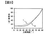
- FIG. 3 shows the film of the present invention.
- the reflectance of P-wave and S-wave having a wavelength of 550 nm when light enters each film from the air.
- the angle dependence of is shown.
- a wavelength of 550 nm is shown here as an example, the relationships shown in FIGS. 1 to 3 have an arbitrary wavelength.
- the conventional transparent film shows a tendency that the P-wave reflectance decreases with an increase in the incident angle, and then becomes 0% and then increases.
- the reflectance of the S wave increases as the incident angle increases.
- the reflectance of is increasing.
- the difference in the reflectance depending on the incident angle between the conventional reflective film and the film of the present invention is the difference in the refractive index in the direction parallel to the film surface of the two types of layers alternately laminated (in-plane refractive index Difference) and the difference in the refractive index in the direction perpendicular to the film surface (difference in the in-plane refractive index). That is, since the conventional reflective film is designed to reflect light by increasing the difference in the in-plane refractive index and the difference in the in-plane refractive index between the two types of layers that are alternately laminated, both the P wave and the S wave are incident. It has a constant reflectance even at an angle of 0 degree, and the reflectance of both P-wave and S-wave increases as the incident angle increases.
- FIG. 5 in which the film of the present invention is arranged on the light guide plate is shown as a schematic diagram for explaining the effect obtained when the film of the present invention is arranged on the emission surface side of the light guide plate. Since the light 6a has a small incident angle on the emission surface 4, most of the light 6a is conventionally emitted to the outside of the light guide plate as shown in FIG. 4, but the film of the present invention has a high reflectance for light in an oblique direction. Therefore, by arranging the film of the present invention on the exit surface side of the light guide plate, it is possible to return the light to the light guide plate by reflecting 6c, which allows the light emitted from the light guide plate to be collected on the front surface more than before. The brightness can be improved.
- the light 6b, 7b, 10b reflected by the film of the present invention and the exit surface of the light guide plate is reflected by the exit surface 5 of the light guide plate.
- 6d, 7d, and 10d are specular reflected light components
- 8, 9 and 11 are light in the front direction of the diffuse reflected light component. Since the film of the present invention has a high transmittance for the light in the front direction, the light 8, 9 and 11 can be transmitted without being reflected. Therefore, when the film of the present invention is used on the emission surface side of the light guide plate, the light emitted from the light guide plate in the front direction is 8, 9, and 11, so that the light emitted from the light guide plate is reduced compared to the conventional case. The light can be condensed on the front surface to improve the brightness.
- the structure of the light guide plate and the traveling direction of light inside the light guide plate described above are examples for explaining the effect of the film of the present invention, and the oblique light emitted from the light guide plate by using the present film. If the concept of reflecting the light back to the light guide plate and transmitting the light in the front direction emitted from the light guide plate is the same, even if the structure of the light guide plate or the traveling direction of the light inside the light guide plate is different from the above description, The function of converging the light emitted from the light plate to the front is exhibited.
- the surface 5 of the light guide plate on the side opposite to the emission surface is a flat surface, but it may be a rough surface or have an uneven shape.
- the film of the present invention does not necessarily have to be arranged right above the light guide plate, and one or more sheets such as a diffusion sheet may be arranged between the light guide plate and the film of the present invention.
- the film of the present invention when used not only for the light guide plate but also for the light source and the direct type surface light source device that emits light in the direction opposite to the light source, the film is emitted obliquely in the conventional manner due to the above effects. Since the light can be converted to the front direction, the emitted light can be focused on the front surface and the brightness can be improved.
- the light source unit of the present invention is a light source unit having a light source and a film, and it is necessary that the light source has an emission band at a wavelength of 450 nm to 650 nm.
- the emission band means an emission spectrum of a light source, a wavelength showing the maximum intensity of the emission spectrum is set as an emission peak wavelength of the light source, and an intensity of 5% or more of the emission intensity at the emission peak wavelength of the light source is shown. It represents the wavelength range of the lowest wavelength and the longest wavelength.
- the luminance of light incident from the light source at an angle of 0° with respect to the normal to the film surface is La (0°)
- the light incident at an angle of 70° with respect to the normal to the film surface is La (0°)
- the brightness of light emitted from the film at an angle of 0° with respect to the normal to the film surface after being incident on the film from the light source is Lb (0°)
- the film surface method is satisfied.
- Lb(0°)/La(0°) in the equation (1) means the brightness maintenance rate (or brightness improvement rate) in the front direction, and the higher the value, the brightness maintenance rate (or brightness improvement rate) in the front direction. ) Is high.
- (0°)/La(0°)>1 light stronger than light incident from the light source at an angle of 0° with respect to the normal to the film surface is 0° to the normal to the film surface. Indicates that the light is emitted at an angle.
- Lb(0°)/La(0°) is preferably more than 1.0, more preferably 1.1 or more, still more preferably 1.2 or more.
- Lb(70°)/La(70°) in the equation (2) means the transmittance of light in the oblique direction, and the smaller the value, the less the light in the oblique direction is transmitted.
- Lb(70°)/La(70°) is preferably smaller than 0.8, more preferably smaller than 0.7.
- the azimuth angle variation of Lb(70°)/La(70°) is 0.3 or less.
- the azimuth variation is Lb (70°) measured at each azimuth (0°, 45°, 90°, 135°) with the azimuth in the longitudinal direction of the light source unit being 0° as shown in FIG. /La (70°) represents the difference between the maximum value and the minimum value.
- a prism sheet which is a general light-condensing film, has unevenness in azimuth angle due to its light-collecting property, so multiple sheets are laminated to eliminate such unevenness, but it is still impossible to completely eliminate unevenness in azimuth angle. Can not.
- the film of the present invention has a small azimuth unevenness, a single sheet can have a light collecting effect.
- the azimuth variation of Lb(70°)/La(70°) is preferably 0.1 or less, more preferably 0.01 or less.
- the stretching include stretching so as to reduce the difference in orientation state between the longitudinal direction and the width direction of the film.
- a light guide plate unit in which the above-mentioned film is arranged on the exit surface side of the light guide plate, a light source unit having the light guide plate unit and a light source, a display device using the light source unit, and a plurality of light sources are provided.
- Examples thereof include an installed substrate, a light source unit in which the above-mentioned film is arranged on the emission surface side of the substrate, and a display device using the light source unit.
- the display device include a liquid crystal display device and an organic EL (Electro-Luminescence) display device.
- Examples of the configuration of the light source unit of the present invention include a light source unit configured to have a configuration such as a reflection film/light guide plate/diffusion sheet/prism sheet and installed to the side of the light guide plate to spread and emit light from a light source, and a plurality of light source units.
- An example is a substrate on which a light source is installed and a light source unit that irradiates light in a direction facing the light source with a structure such as a reflective film/diffuser/prism sheet on the exit surface side of the substrate.
- the reflective film may be a film that diffusely reflects or specularly reflects, and a film having particularly high diffuse reflectance is preferable, and a white reflective film is preferable.
- the number of the diffusion film or the prism sheet is one, and a configuration in which two or more sheets are used may be adopted.
- the light source include a white light source, a red, blue, and green monochromatic light source, and a combination of two types of these monochromatic light sources.
- the light emission band has a range of 450 nm to 650 nm, and the light emission method is an LED (Light Emitting Diode), Examples include CCFL (Cold Cathode Fluorescent Lamp) and organic EL.
- the film of the present invention is preferably used by arranging it on the emission surface side of the light guide plate if it is a light source unit using a light guide plate.
- a light source and a light source unit that emits light in a direction facing the light source are preferably used by being disposed on the emission surface side of the diffusion plate. Further, it is preferable not only to install the device with an air gap, but also to bond it to another member with an adhesive agent or an adhesive agent.
- An example of the configuration of a display device using the light source unit of the present invention has a configuration in which a diffusion sheet/prism sheet/polarization reflection film is arranged in this order, and the film of the present invention is provided between the diffusion sheet and the polarization reflection film.
- An example of the display device is a display device. With such a configuration, it is possible to condense in the front direction the emitted light that has been erased by the diffusion sheet but has strong oblique light. Further, even if a polarizing plate or a liquid crystal cell is installed on the viewing side of the polarized reflection film, it is possible to suppress the occurrence of rainbow unevenness in which the display screen becomes iridescent.
- a display device having a structure in which a reflection film/light guide plate/diffusion sheet/prism sheet/polarization reflection film is arranged in that order, and the film of the present invention is arranged between the diffusion sheet and the polarization reflection film
- a display device having a structure in which a reflection film/light source/diffusion sheet/prism sheet/polarization reflection film is arranged in that order, and the film of the present invention is arranged between the diffusion sheet and the polarization reflection film. It is mentioned as an aspect.
- An example of the configuration of the display device of the present invention is a display device including an infrared sensor.
- a display device provided with an infrared sensor can have an authentication function for identifying a user by authenticating a fingerprint, a face, an iris of an eye, or the like with infrared rays.
- an infrared sensor can be provided with a function of operating the display device by detecting movements of the user's fingers, hands, eyes, and the like. It is preferable that the display device member between the infrared sensor that receives infrared light and the object to be discriminated has high infrared parallel light transmittance.
- the film of the present invention preferably has a maximum parallel light transmittance of 50% or more, and more preferably 70%, of light incident at an angle of 0° with respect to the normal line of the film surface at a wavelength of 800 nm to 1600 nm.
- the above is more preferably 80% or more, and particularly preferably 85% or more.
- the emission/reception wavelength of the infrared sensor is in the range of 800 nm to 1600 nm, and examples of peak wavelengths include 850 nm, 905 nm, 940 nm, 950 nm, 1200 nm, 1550 nm.
- the structure of the light source unit used for the display device having the infrared sensor is a light source that spreads the light of the light source installed beside the light guide plate on the surface and emits it with a structure such as a reflection film/light guide plate/diffusion sheet/film of the present invention.
- Examples thereof include a unit and a substrate on which a plurality of light sources are installed, and a light source unit that irradiates light in a direction facing the light source with a configuration such as a reflection film/diffusion plate/film of the present invention on the emission surface side of the substrate.
- the display device member between the infrared sensor and the object to be discriminated has a high infrared parallel light transmittance and an infrared scattering rate (infrared haze). Is preferably low.
- the prism sheet which is shaped like a triangle (prism) on a flat substrate, exerts its condensing effect not only on visible light but also on infrared light. Further, when light (visible light/infrared light) is incident from the surface of the base material, a light-collecting effect is exhibited, but light (visible light/infrared light) incident from the prism surface is diffused. Further, it has a high reflectance for light having an incident angle of 0° which is incident from the surface of the base material. Therefore, when the infrared information detected by the infrared sensor passes through the prism sheet, the infrared information is disturbed due to phenomena such as light collection, diffusion, and reflection. When the infrared information is disturbed, there is a problem that the detection accuracy of the infrared sensor decreases. When such a phenomenon occurs, it is not preferable to use the prism sheet.
- the film of the present invention in the film of the present invention, light incident at an angle of 0° with respect to the normal to the film surface does not disturb infrared information because not only visible light transmittance but also infrared parallel light transmittance is high. Therefore, when the film of the present invention is used in a display device having an infrared sensor, it is possible to achieve both improved brightness and improved infrared detection accuracy.
- the display device of the present invention is preferably provided with a viewing angle control layer.
- the viewing angle control layer is preferably arranged in the display device further on the emission surface side than the position where the film of the present invention is arranged.
- An example of the viewing angle control layer is a liquid crystal layer, in which liquid crystal molecules in the liquid crystal layer change in orientation from an oblique direction to a horizontal direction or are oriented from a horizontal direction to an oblique direction in response to electric current to the liquid crystal molecules. It is preferable that the liquid crystal molecule has a characteristic of changing.
- the viewing angle is controlled to the front when the alignment of the liquid crystal layer is in the oblique direction and to the wide angle when the alignment of the liquid crystal layer is in the horizontal direction.
- the film of the present invention comprises three or more layers in which a layer (A layer) made of the thermoplastic resin A and a layer (B layer) made of a thermoplastic resin B different from the thermoplastic resin A are alternately laminated. It is preferable that the multilayer laminated film is
- the term “different” of the thermoplastic resin B different from the thermoplastic resin A as used herein means that any of crystalline/amorphous, optical property and thermal property is different.
- the difference in optical properties means that the refractive index differs by 0.01 or more, and the difference in thermal properties means that the melting point or the glass transition temperature differs by 1° C. or more.
- thermoplastic resins when one resin has a melting point and the other resin does not have a melting point, or when one resin has a crystallization temperature and the other resin has a crystallization temperature. If not, it means having different thermal properties.
- thermoplastic resins having different properties it is possible to give the film a function which cannot be achieved by a single layer film of each thermoplastic resin.
- thermoplastic resin used in the film of the present invention examples include polyolefins such as polyethylene, polypropylene, and poly(4-methylpentene-1), and examples of cycloolefins include ring-opening metathesis polymerization, addition polymerization, and the like of norbornenes.
- Aliphatic polyolefins that are addition copolymers with olefins, biodegradable polymers such as polylactic acid and polybutylsuccinate, polyamides such as nylon 6, nylon 11, nylon 12, nylon 66, aramids, polymethylmethacrylate, Polyvinyl chloride, polyvinylidene chloride, polyvinyl alcohol, polyvinyl butyral, ethylene vinyl acetate copolymer, polyacetal, polyglycolic acid, polystyrene, styrene copolymer polymethylmethacrylate, polycarbonate, polypropylene terephthalate, polyethylene terephthalate, polybutylene terephthalate, polyethylene-2 Polyester such as 6-naphthalate, polyether sulfone, polyether ether ketone, modified polyphenylene ether, polyphenylene sulfide, polyetherimide, polyimide, polyarylate, tetrafluoroethylene resin, trifluoroethylene resin
- polyester from the viewpoints of strength, heat resistance and transparency, it is particularly preferable to use polyester, and as the polyester, polymerization from a monomer having aromatic dicarboxylic acid or aliphatic dicarboxylic acid and diol as main constituent components
- the polyester obtained by is preferable.
- aromatic dicarboxylic acid for example, terephthalic acid, isophthalic acid, phthalic acid, 1,4-naphthalenedicarboxylic acid, 1,5-naphthalenedicarboxylic acid, 2,6-naphthalenedicarboxylic acid, 4,4′-diphenyl
- aromatic dicarboxylic acid for example, terephthalic acid, isophthalic acid, phthalic acid, 1,4-naphthalenedicarboxylic acid, 1,5-naphthalenedicarboxylic acid, 2,6-naphthalenedicarboxylic acid, 4,4′-diphenyl
- dicarboxylic acid 4,4'-diphenyl ether dicarboxylic acid
- 4,4'-diphenyl sulfone dicarboxylic acid 4,4'-diphenyl sulfone dicarboxylic acid.
- aliphatic dicarboxylic acid examples include adipic acid, suberic acid, sebacic acid, dimer acid, dodecanedioic acid, cyclohexanedicarboxylic acid and ester derivatives thereof. Of these, terephthalic acid and 2,6-naphthalenedicarboxylic acid are preferred. These acid components may be used alone or in combination of two or more, and further, an oxy acid such as hydroxybenzoic acid may be partially copolymerized.
- diol component examples include ethylene glycol, 1,2-propanediol, 1,3-propanediol, neopentyl glycol, 1,3-butanediol, 1,4-butanediol and 1,5-pentanediol. 1,6-hexanediol, 1,2-cyclohexanedimethanol, 1,3-cyclohexanedimethanol, 1,4-cyclohexanedimethanol, diethylene glycol, triethylene glycol, polyalkylene glycol, 2,2-bis(4- Hydroxyethoxyphenyl)propane, isosorbate, spiroglycol and the like can be mentioned. Among them, ethylene glycol is preferably used. These diol components may be used alone or in combination of two or more.
- polyesters polyethylene terephthalate and its copolymers, polyethylene naphthalate and its copolymers, polybutylene terephthalate and its copolymers, polybutylene naphthalate and its copolymers, and further polyhexamethylene terephthalate and its copolymers. It is preferred to use polymers and polyesters selected from polyhexamethylene naphthalate and copolymers thereof.
- thermoplastic resins having different properties used is that the absolute value of the difference in the glass transition temperature of each thermoplastic resin is 20° C. or less. Preferably. This is because when the absolute value of the difference in glass transition temperature is larger than 20° C., drawing defects are likely to occur during production of the multilayer laminated film.
- thermoplastic resins having different properties to be used is that the absolute value of the difference between SP values (also referred to as solubility parameters) of the respective thermoplastic resins is It is particularly preferably 1.0 or less.
- the absolute value of the difference in SP value is 1.0 or less, delamination becomes difficult to occur.
- the polymers having different properties are preferably composed of combinations providing the same basic skeleton.
- the basic skeleton referred to here is a repeating unit that constitutes a resin.
- the other thermoplastic resin is used from the viewpoint of easily realizing a highly accurate laminated structure.
- the resin preferably contains ethylene terephthalate, which has the same basic skeleton as polyethylene terephthalate.
- the polyester resins having different optical properties are resins containing the same basic skeleton, the stacking accuracy is high and further delamination at the stacking interface is less likely to occur.
- Copolymers are desirable in order to have the same basic skeleton and different properties. That is, for example, when one resin is polyethylene terephthalate, the other resin is a resin composed of an ethylene terephthalate unit and another repeating unit having an ester bond.
- the ratio of other repeating units (sometimes referred to as the amount of copolymerization) is preferably 5 mol% or more from the viewpoint of obtaining different properties, while the difference in the adhesiveness between layers and the difference in heat flow characteristics are small. 90 mol% or less is preferable because it is excellent in thickness accuracy and thickness uniformity. More preferably, it is 10 mol% or more and 80 mol% or less.
- the A layer and the B layer are each made of a blend or alloy of plural kinds of thermoplastic resins.
- thermoplastic resins By blending or alloying a plurality of types of thermoplastic resins, it is possible to obtain performance that cannot be obtained with one type of thermoplastic resin.
- the thermoplastic resin A and/or the thermoplastic resin B is preferably polyester, and the thermoplastic resin A contains polyethylene terephthalate as a main component and the thermoplastic resin.
- B comprises terephthalic acid as a dicarboxylic acid component and ethylene glycol as a diol component, and further, at least one of naphthalenedicarboxylic acid, cyclohexanedicarboxylic acid as a dicarboxylic acid component, cyclohexanedimethanol, spiroglycol, and isosorbide as a diol component.
- thermoplastic resin A means that it accounts for 70% by weight or more of the entire resin constituting the layer A.
- main component of the thermoplastic resin B means that it accounts for 35% by weight or more of the whole resin constituting the B layer.
- the film of the present invention has an average transmittance of 70% or more at a wavelength of 450 nm to 650 nm of light when incident at an angle of 0° with respect to the normal to the film surface, and is 20° with respect to the normal to the film surface.
- Rp20 ⁇ Rp40 ⁇ Rp70 where Rp20, Rp40, and Rp70 are the average reflectances (%) of wavelengths 450 nm to 650 nm of the respective P-waves when incident at 40° and 70°.
- Rp70 is 30% or more.
- the film of the present invention is a multilayer laminated film in which A layers and B layers are alternately laminated, and the difference in the in-plane refractive index between the A layer and the B layer is small and the difference in the in-plane refractive index between the A layer and the B layer. Is preferably large.
- the difference in in-plane refractive index between the A layer and the B layer is preferably 0.03 or less, more preferably 0.02 or less, and further preferably 0.01 or less.
- the difference in the in-plane refractive index between the A layer and the B layer is preferably more than 0.03, more preferably 0.06 or more, still more preferably 0.09 or more.
- the resin constituting the A layer and the B layer is a thermoplastic resin and one layer (the A layer) is constituted.
- the thermoplastic resin containing crystalline polyester as a main component, and the thermoplastic resin forming the other layer (B layer) has a melting point of 20° C. or more lower than that of the amorphous polyester or the polyester forming the A layer.
- the difference between the in-plane refractive indices of the A layer and the B layer is 0.04 or less, and the difference between the glass transition temperatures of the resins forming the A layer and the B layer is 20° C. or less. Can be mentioned.
- thermoplastic resin In order to reduce the in-plane refractive index difference between the A layer and the B layer and increase the in-plane refractive index difference, one thermoplastic resin is strongly oriented in a direction parallel to the film surface (parallel to the film surface). While the refractive index in the direction perpendicular to the film surface is large and the refractive index in the direction perpendicular to the film surface is small), the other thermoplastic resin maintains the isotropic property (direction parallel to the film surface and perpendicular to the film surface). It is important that the refractive index is the same).
- thermoplastic resin forming the layer A is a crystalline polyester, it can be strongly oriented in a direction parallel to the film surface, and the thermoplastic resin forming the layer B is an amorphous polyester or A
- the crystalline polyester having a melting point lower than that of the layer by 20° C. or more can be isotropic.
- the A layer is oriented and crystallized by using a crystalline resin, and the B layer is made to be amorphous.
- the refractive index is isotropic and the refractive index is high.
- the refractive index in the direction parallel to the film surface (in-plane direction) increases, and the refractive index in the direction perpendicular to the film surface (perpendicular direction) decreases.
- thermoplastic resin used in the A layer has a low aromatic content orientation.
- a crystalline resin may be used, and as the amorphous resin used for the layer B, an amorphous resin having a high aromatic content or a crystalline resin having a melting point of 20° C. or more lower than that of the orientation/crystalline resin may be laminated. preferable.
- the glass transition temperature of the orientation/crystalline resin is low, and the amorphous resin or the orientation/ The glass transition temperature of a crystalline resin having a melting point lower than that of the crystalline resin by 20° C. or more tends to be high.
- a film having desired reflection performance may not be obtained. Therefore, by setting the difference in glass transition temperature of the thermoplastic resin constituting the multilayer stack to 20° C. or less, it becomes easy to sufficiently orient the resin to be oriented and to set Rp to 30% or more.
- an oriented/crystalline thermoplastic resin and an amorphous resin, or a crystalline resin having a melting point lower than that of the oriented/crystalline resin by 20° C. or more is formed at a film stretching temperature at which orientation/crystallization is accelerated. Therefore, the transparency in the direction perpendicular to the film surface and the excellent reflection performance in the oblique direction to the film surface can both be easily achieved.
- the difference between the glass transition temperatures of the A layer and the B layer is more preferably 15° C. or higher, and even more preferably 5° C. or lower. As the difference in glass transition temperature becomes smaller, it becomes easier to adjust the film stretching conditions, and it becomes easier to improve the optical performance.
- the thermoplastic resin constituting the layer B contains a structure derived from alkylene glycol having a number average molecular weight of 200 or more.
- the thermoplastic resin constituting the layer B contains a structure derived from alkylene glycol having a number average molecular weight of 200 or more.
- the in-plane average refractive index of each layer constituting the laminated film can be increased and the glass transition temperature can be easily lowered.
- alkylene glycol examples include polyethylene glycol, polytrimethylene glycol, polytetramethylene glycol and the like.
- the molecular weight of the alkylene glycol is more preferably 200 or more, further preferably 300 or more and 2000 or less.
- the molecular weight of the alkylene glycol is less than 200, alkylene glycol is not sufficiently incorporated into the polymer due to its high volatility during the synthesis of the thermoplastic resin, and as a result, the effect of lowering the glass transition temperature is sufficient. May not be obtained.
- the molecular weight of the alkylene glycol is larger than 2000, the reactivity may decrease during the production of the thermoplastic resin, and the film may not be suitable for production.
- the thermoplastic resin constituting the layer B contains a structure derived from two or more kinds of aromatic dicarboxylic acids and two or more kinds of alkyl diols, and an alkylene glycol having a number average molecular weight of 200 or more. It is preferable to include a structure derived from By including such a structure in the B layer, a high refractive index comparable to the in-plane refractive index of the A layer, which is an oriented crystalline resin, is realized in an amorphous state, and it is co-stretched with a crystalline thermoplastic resin. It is necessary to indicate possible glass transition temperatures. It is difficult to satisfy all these requirements with a single dicarboxylic acid or alkylene diol.
- the film of the present invention preferably has a P-wave reflectance of 30% or more, and more preferably 50%, in the wavelength range of 400 nm to 700 nm when incident at an angle of 70° with respect to the normal to the film surface. Or more, and more preferably 70% or more.
- the film of the present invention has a property that the reflection wavelength band shifts to the lower wavelength side as the incident angle increases.
- the reflectance of P waves in the wavelength range of 400 nm to 700 nm when incident at an angle of 70° with respect to the normal to the film surface is 30% or more, so that even at an incident angle of 70° or more. It can have a sufficient reflectance in the wavelength range of 450 nm to 650 nm which is the emission band of the light source.
- the average reflectance Rp70 of the P-wave wavelength 450 nm to 650 nm when incident at an angle of 70° with respect to the normal to the film surface, and the average reflectance Rp70 at an angle of 70° with respect to the normal to the film surface is preferably 1 or more, more preferably 1.2 or more, further preferably 1.5 or more. Since the reflectance of P-wave when it is incident at an angle of 70° is high, the effect of condensing and improving the brightness when using the film of the present invention is high.
- the average reflectance Rp40 of the P-wave wavelength of 450 nm to 650 nm when incident at an angle of 40° with respect to the normal to the film surface, and the average reflectance Rp40 at an angle of 40° with respect to the normal to the film surface is preferably 1 or more, more preferably 1.2 or more, and further preferably 1.5 or more.
- the method for adjusting the reflectance in the desired wavelength range is as follows: the difference in the in-plane refractive index between the A layer and the B layer, the number of layers, the layer thickness distribution, and the film forming conditions (for example, draw ratio, draw speed, draw temperature, heat treatment temperature, heat treatment time). ) Adjustment and the like.
- the A layer and the B layer it is preferable that the A layer is made of a crystalline thermoplastic resin and the B layer is made of a resin containing an amorphous thermoplastic resin as a main component.
- the resin containing an amorphous thermoplastic resin as a main component means that the weight ratio of the amorphous thermoplastic resin is 70% or more.
- the number of laminated layers is preferably 101 layers or more, more preferably 401 layers or more, and further preferably 601.
- the number of layers is at least 5,000, and the upper limit is about 5,000 from the viewpoint of increasing the size of the laminating apparatus.
- the optical thicknesses of the adjacent A layer and B layer satisfy the following expression (A).
- ⁇ is the reflection wavelength
- n A is the in-plane refractive index of the A layer
- d A is the thickness of the A layer
- n B is the in-plane refractive index of the B layer
- d B is the thickness of the B layer.
- the layer thickness distribution is a constant layer thickness distribution from one side of the film to the opposite side, a layer thickness distribution that increases or decreases from one side of the film to the opposite side, or from one side of the film.
- a layer thickness distribution that decreases after the layer thickness increases toward the film center, a layer thickness distribution that increases after the layer thickness decreases from one side of the film toward the film center, and the like are preferable.
- the layer thickness distribution can be changed in a linear manner, a geometrical ratio, a difference sequence, or continuously varying, or about 10 to 50 layers have almost the same layer thickness, and the layer thickness is stepwise. Those that change are preferred.
- a layer having a layer thickness of 3 ⁇ m or more can be preferably provided as a protective layer on both surface layers of the multilayer laminated film.
- the thickness of the protective layer is preferably 5 ⁇ m or more, more preferably 10 ⁇ m or more. By increasing the thickness of the protective layer, it is possible to suppress flow marks during film formation, suppress the deformation of the thin film layer in the multilayer laminated film after laminating with another film or a molded product and the laminating process, and press resistance. Can be mentioned.
- the thickness of the multilayer laminated film is not particularly limited, but is preferably 20 ⁇ m to 300 ⁇ m, for example. If it is less than 20 ⁇ m, the film may have a poor rigidity and may be poor in handleability. On the other hand, when it exceeds 300 ⁇ m, the film may be too stiff and the moldability may be deteriorated.
- the film of the present invention needs to have an average transmittance of 70% or more at a wavelength of light of 450 nm to 650 nm when incident at an angle of 0° with respect to the normal to the film surface. It is more preferably 85% or more, still more preferably 90% or more. It is preferable that the transmittance of light incident perpendicularly to the film surface is higher, because the light-collecting effect when the film of the present invention is used is higher. As a method of increasing the transmittance of light incident perpendicularly to the film surface, the difference in the in-plane refractive index between the A layer and the B layer is reduced, and a primer layer, a hard coat layer, or an antireflection layer is provided on the film surface. Is preferred. By providing a layer having a refractive index lower than that of the resin on the film surface, it is possible to increase the transmittance of light that is vertically incident on the film surface.
- the film of the present invention has a primer layer, a hard coat layer, an abrasion resistant layer, an anti-scratch layer, an antireflection layer, a color correction layer, an ultraviolet absorbing layer, a light stabilizing layer (HALS), a heat ray absorbing layer on the surface of the film. It may have a functional layer such as a printing layer, a gas barrier layer and an adhesive layer. These layers may be one layer or multiple layers, and one layer may have a plurality of functions. Further, the multilayer laminated film may contain additives such as an ultraviolet absorber, a light stabilizer (HALS), a heat ray absorber, a crystal nucleating agent and a plasticizer.
- HALS light stabilizer
- the film of the present invention preferably has a retardation of 2000 nm or less.
- the resin is selected so that the difference in the refractive index in either direction becomes small, they are orthogonal to each other.
- the refractive index in the direction becomes large. As a result, it may be difficult to achieve transparency in the direction perpendicular to the film surface.
- the retardation which is a parameter relating to the anisotropy of the alignment state
- the phase difference is preferably 1000 nm or less, more preferably 500 nm or less.
- a laminated structure having three or more layers can be produced by the following method.
- a thermoplastic resin is supplied from two extruders, an extruder A corresponding to the A layer and an extruder B corresponding to the B layer, and the polymer from each flow path is a multi-manifold type feed block which is a known laminating device.
- a method of using a square mixer or a comb-type feed block alone is used to laminate three or more layers.
- melt is melt-extruded into a sheet using a T-type die or the like, and then cooled and solidified on a casting drum to obtain an unstretched multilayer laminated film.
- the methods described in JP2007-307893A, JP46919910A, and JP48164419A are preferable.
- the unstretched multilayer laminated film is stretched and heat-treated.
- a stretching method it is preferable to perform biaxial stretching by a known sequential biaxial stretching method or a simultaneous biaxial stretching method.
- the stretching temperature is preferably in the range of not less than the glass transition temperature of the unstretched multilayer laminated film to not more than the glass transition temperature +80°C.
- the stretching ratio is preferably in the range of 2 to 8 times in the longitudinal direction and in the width direction, more preferably in the range of 3 to 6 times, and it is preferable to reduce the difference in the stretching ratio between the longitudinal direction and the width direction.
- the stretching in the longitudinal direction is preferably performed by utilizing the speed change between the rolls of the longitudinal stretching machine.
- the stretching in the width direction uses a known tenter method. That is, the film is conveyed while being gripped by both ends of the film, and is stretched in the width direction by widening the clip interval between both ends of the film. In addition, it is also preferable that the stretching in the tenter is simultaneous
- the unstretched film cast on the cooling roll is guided to a simultaneous biaxial tenter, conveyed while gripping both ends of the film with clips, and stretched simultaneously and/or stepwise in the longitudinal direction and the width direction. Stretching in the longitudinal direction is achieved by increasing the distance between the clips of the tenter, and in the width direction by increasing the distance between the rails on which the clips run. It is preferable that the tenter clip to be stretched and heat treated in the present invention is driven by a linear motor system. In addition, there are a pantograph method, a screw method, and the like. Among them, the linear motor method is excellent in that the stretching ratio can be freely changed because each clip has a high degree of freedom.
- the heat treatment temperature is preferably in the range of the stretching temperature or higher to the melting point of the thermoplastic resin of the layer A-10°C or less, and it is also preferable to carry out a cooling step in the range of heat treatment temperature-30°C or less after the heat treatment.
- a cooling step in the range of heat treatment temperature-30°C or less after the heat treatment.
- the relaxation rate is preferably in the range of 1% to 10%, more preferably in the range of 1% to 5%.
- the film of the present invention will be described with reference to specific examples. Even when a thermoplastic resin other than the thermoplastic resins specifically exemplified below is used, the film of the present invention can be obtained in the same manner by considering the description of the present specification including the following examples. .. [Measurement method of physical properties and evaluation method of effect] The method of evaluating physical properties and the method of evaluating effects are as follows.
- Main orientation axis direction The sample size was 10 cm ⁇ 10 cm, and the sample was cut out at the center of the film width direction.
- the main orientation axis direction was determined using a molecular orientation meter MOA-2001 manufactured by KS Systems Co., Ltd. (currently Oji Scientific Instruments Co., Ltd.).
- Rp20, Rp40, and Rp70 are obtained as average reflectances of P waves in the wavelength range of 450 nm to 650 nm at incident angles of 20°, 40°, and 70°, and Rs20, Rs40 as average reflectances of S waves, Rs70 was calculated, and Rp40/Rs40 and Rp70/Rs70 were calculated. Further, the inclination directions of 20°, 40°, and 70° were the directions along the main alignment axis of the film.
- Refractive index A resin pellet vacuum dried at 70° C. for 48 hours was melted at 280° C., pressed with a pressing machine, and then rapidly cooled to form a sheet having a thickness of 500 ⁇ m.
- the refractive index of the prepared sheet was measured using an Abbe refractometer (NAR-4T) manufactured by Atago Co. and a NaD ray lamp.
- Phase difference A phase difference measuring device (KOBRA-21ADH) manufactured by Oji Scientific Instruments was used. A film sample cut out with a size of 3.5 cm ⁇ 3.5 cm was placed in the apparatus, and the retardation at a wavelength of 590 nm at an incident angle of 0° was measured.
- Backlight 1 32-inch white LED edge type backlight, light emission band of 425 nm to 652 nm
- Backlight 2 43-inch white LED direct backlight, light emission band of 418 nm to 658 nm
- the brightness was measured by using BM-7 manufactured by Topcon and an angle variable unit to measure the light receiving angles of +70°, ⁇ 70°, and 0°, and the brightness of 70° was an average value of +70° and ⁇ 70°.
- the azimuth angle inclined to the light receiving angle of 70° is the longitudinal direction of the backlight, and the luminances La (0°) and La (70°) of the incident light at angles of 0° and 70° with respect to the normal to the film surface of the present invention.
- the luminance of light emitted at angles of 0° and 70° with respect to the normal line of the film surface of the present invention from Lb(0°) and Lb(70°) to the formulas (1) and (2). was calculated.
- a coating liquid for forming a laminated film composed of resin)/(polyester resin having a glass transition temperature of 82° C.)/silica particles having an average particle diameter of 100 nm was applied. After that, the both ends are guided to a tenter which holds them with clips, laterally stretched 3.5 times at 100°C, then heat-treated at 210°C and relaxed in the width direction by 5%, cooled at 100°C, and then a multilayer with a thickness of 60 ⁇ m. A laminated film was obtained. Table 1 shows the physical properties of the obtained film.
- a coating liquid for forming a laminated film composed of resin)/(polyester resin having a glass transition temperature of 82° C.)/silica particles having an average particle diameter of 100 nm was applied. After that, the both ends are guided to a tenter that holds them with clips, laterally stretched 3.5 times at 100°C, then heat-treated at 210°C and relaxed in the width direction by 5%, and cooled at 100°C. A laminated film was obtained. Table 1 shows the physical properties of the obtained film.
- Example 5 The two multilayer laminated films prepared in Example 4 were laminated with a laminator using a 25 ⁇ m thick acrylic optical adhesive. Table 1 shows the physical properties of the produced film.
- Resin B was used as the thermoplastic resin. It is melted at 280°C in an extruder, passed through 5 FSS type leaf disk filters, then fed to a T-die, shaped into a sheet, and then subjected to electrostatic application voltage of 8 kV with a wire, while being subjected to surface temperature. An unstretched film was obtained by rapid cooling and solidification on a casting drum kept at 25°C. This unstretched film was longitudinally stretched at 90° C. and a draw ratio of 3.3 times, and both surfaces of the film were subjected to corona discharge treatment in air, and the treated surfaces on both sides of the film (polyester having a glass transition temperature of 18° C.
- a coating liquid for forming a laminated film composed of resin)/(polyester resin having a glass transition temperature of 82° C.)/silica particles having an average particle diameter of 100 nm was applied. After that, the both ends are guided to a tenter which holds them with clips, and transversely stretched 3.5 times at 100° C., then heat treatment at 210° C. and 5% width direction relaxation are performed, and after cooling at 100° C., a film having a thickness of 50 ⁇ m Got Table 1 shows the physical properties of the obtained film.
- Example 2 A multilayer laminated film having a thickness of 110 ⁇ m was obtained in the same manner as in Example 4 except that the resin E was used as the thermoplastic resin forming the layer B. Table 1 shows the physical properties of the obtained film.
- Table 2 shows the backlight configuration, the position where the film is arranged, and the measured front luminance (in the table, the front relative luminance represents the front luminance when the luminance of the conventional configuration without a film is 100%). .. As shown in Table 2, it can be seen that the light source unit using the film of the present invention has improved front brightness as compared with the conventional backlight configuration and the configuration using the conventional film.
- the brightness was measured using a 43-inch white LED direct type backlight (backlight 2).
- the light source is a conventional direct type backlight (a light source is installed on a substrate, and a white reflective film in which the light source position is hollowed out is installed on the substrate) (1)
- the films of Example 1, Example 4, Example 5, Comparative Example 1, and Comparative Example 2 are arranged at the positions shown in Table 3, respectively, the front luminance of the entire light source unit, the luminance incident on the film, and the emission from the film.
- Table 3 shows the backlight configuration, the position where the film is arranged, and the measured front luminance (in the table, the front relative luminance represents the front luminance when the luminance of the conventional configuration without the film is 100%). ..
- the present invention relates to a light source unit, a display device, and a film with front luminance further improved than before.
Abstract
Provided are a light source unit, a display device, and a film such that light collection ability and front surface luminance are improved over the prior art. The light source unit has a light source and a film, the light source has a light-emitting band in the 450-650 nm wavelength range, the film has a mean transmittance of 70% or higher for light in the 450-650 nm wavelength range from the light source and incident at an angle of 0° to the normal to the film surface, the film satisfies the relationship Rp20 ≤ Rp40 < Rp70 with Rp70 being 30% or greater when Rp20, Rp40, and Rp70 represent the mean reflectance (%) for P waves in the 450-650 nm wavelength range for light from the light source incident at angles of 20°, 40°, and 70° to the normal to the film surface, and the light source and the film satisfy specific relationships. Lb(0°)/La(0°) ≥ 0.8 ··· (1) Lb(70°)/La(70°) < 1.0 ··· (2)
Description
本発明は、光源ユニット、表示装置及びフィルムに関する。
The present invention relates to a light source unit, a display device and a film.
液晶ディスプレイなどの表示装置に用いる光源の一つとして、少なくとも一つの光源から入射した光を面状に拡げて射出する面光源装置が用いられている。この面光源装置は、少なくとも光源とその光源の光を面状に拡げる導光板から構成されるエッジ型や光源とその光源に対向する方向に光を照射する直下型などが挙げられる。一般的に表示装置は正面方向を0°とした場合±45°程度の角度範囲が視認範囲であり、これ以上大きな角度で出射された光は損失となる。一方、エッジ型の面光源装置は導光板から出射された光は無制御に拡散されているため、導光板から出射された光の強度が最も大きい角度は、一般的に正面方向ではなく斜め方向である。これは、光源から導光板の端部へ入射された光が、斜め方向に反射しながら導光板の中を面状に拡がるため、正面方向よりも斜め方向の光が出射され易いためである。そこで、従来では導光板の出射面側に拡散シートやプリズムシートを複数枚配することで、導光板から出射される斜め方向の光を正面方向に集光させ正面輝度を向上させていた(特許文献1、特許文献2)。直下型の面光源装置は面光源を得るために光源を複数配置し、光源間の光ムラを抑制するためレンズ等を用いて光源から出射される光を正面だけでなく斜め方向に拡げ、更に拡散シートなどを通過させることでムラを消し、拡散シートやプリズムシートを複数枚配することで正面方向に集光させ正面輝度を向上させていた。
As one of the light sources used for display devices such as liquid crystal displays, surface light source devices that spread the light incident from at least one light source in a plane and emit it are used. Examples of the surface light source device include an edge type including at least a light source and a light guide plate that spreads the light of the light source in a planar shape, and a direct type that emits light in a direction facing the light source. Generally, in a display device, an angle range of about ±45° is a visible range when the front direction is 0°, and light emitted at a larger angle than this is a loss. On the other hand, in the edge type surface light source device, the light emitted from the light guide plate is uncontrolledly diffused, so that the angle at which the intensity of the light emitted from the light guide plate is the largest is generally not the front direction but the oblique direction. Is. This is because the light that has entered the end portion of the light guide plate from the light source spreads in the surface of the light guide plate while being reflected in the oblique direction, so that the light in the oblique direction is more likely to be emitted than in the front direction. Therefore, conventionally, by arranging a plurality of diffusion sheets or prism sheets on the exit surface side of the light guide plate, oblique light emitted from the light guide plate is condensed in the front direction to improve the front brightness (Patent Reference 1, Patent Reference 2). The direct type surface light source device has a plurality of light sources arranged in order to obtain a surface light source, and spreads the light emitted from the light source not only in the front but also in an oblique direction by using a lens or the like to suppress light unevenness between the light sources. By passing through a diffusion sheet or the like, the unevenness is eliminated, and by arranging a plurality of diffusion sheets or prism sheets, the light is condensed in the front direction to improve the front brightness.
しかしながら、拡散シートやプリズムシートはその構造上、浅い角度で侵入する光全ては集光させることはできないため、拡散シートやプリズムシートを用いてもエッジ型の導光板や直下型の拡散シートから出射される全ての斜め方向の光を正面方向に集光させることは困難であった。
However, due to the structure of the diffusion sheet and prism sheet, it is not possible to collect all the light that enters at a shallow angle, so even if a diffusion sheet or prism sheet is used, it will be emitted from the edge-type light guide plate or direct type diffusion sheet. It was difficult to condense all the light in the oblique direction to the front direction.
導光板を用いた従来の面光源を説明する模式図として、導光板の断面の一部を図4に示す。4は導光板の出射面であり、5は導光板の出射面の反対側の面であり、導光板の出射面側の媒質は一例として空気としている。導光板内部を斜め方向に反射しながら面上に拡がっている光6a、7aについて、6aは出射面4への入射角度が小さく、7aは出射面4への入射角度が大きい光である。それぞれの光が出射面4に入射すると、光6aはその反射率に応じて一部の光が反射光6bとなり導光板に戻り、残りの光6cは導光板の外側に出射される。その後、光6bは導光板の出射面の反対側の面5で反射される。この反射光のうち6dは正反射光成分であり、8は拡散反射光成分のうち正面方向の光である。次に、光7aは出射面4への入射角度が大きいため、出射面4に入射すると全反射され、その反射光7bは導光板の出射面の反対側の面5で反射される。この反射光のうち7dは正反射光成分であり、9は拡散反射光成分のうち正面方向の光である。以上のように導光板の内部の光は斜め方向に反射しながら面上に拡がりつつ、その光の一部6c、8、9が導光板から出射されることで面上の出射光を得ることができる。しかしながら、光7aよりも出射面4への入射角度が小さい光(すなわち6aのような光)は出射面4に入射した際に、導光板の外側に斜め方向に出射される光(すなわち6cのような光)が発生するため、この方法では導光板から出射する光の分布が正面方向だけでなく斜め方向にも出射されるので、正面方向の光の強さが低下することが課題である。かかる課題を解決するため、従来の方法では、拡散シートやプリズムシートを導光板の出射面側に配することで、導光板から出射された斜め方向の光の向きを正面方向に変換することで対応していた。しかしながら、拡散シートやプリズムシートはその構造上、浅い角度で侵入する光(入射角度が小さい光)全てを集光させることはできないため、拡散シートやプリズムシートを用いても導光板から出射される全ての斜め方向の光を正面方向に集光させることはできなかった。
As a schematic diagram for explaining a conventional surface light source using a light guide plate, FIG. 4 shows a part of the cross section of the light guide plate. Reference numeral 4 denotes an exit surface of the light guide plate, 5 denotes a surface opposite to the exit surface of the light guide plate, and the medium on the exit surface side of the light guide plate is air as an example. Regarding the lights 6a and 7a that are reflected on the inside of the light guide plate in an oblique direction and are spread on the surface, 6a has a small incident angle to the emission surface 4, and 7a has a large incident angle to the emission surface 4. When the respective lights are incident on the emission surface 4, a part of the light 6a becomes reflected light 6b according to the reflectance thereof and returns to the light guide plate, and the remaining light 6c is emitted to the outside of the light guide plate. After that, the light 6b is reflected by the surface 5 of the light guide plate opposite to the emission surface. Of this reflected light, 6d is the specular reflection light component, and 8 is the light in the front direction of the diffuse reflection light component. Next, since the light 7a has a large incident angle on the emission surface 4, when the light 7a is incident on the emission surface 4, the light 7a is totally reflected, and the reflected light 7b is reflected on the surface 5 opposite to the emission surface of the light guide plate. Of this reflected light, 7d is the specular reflected light component, and 9 is the light in the front direction of the diffuse reflected light component. As described above, the light inside the light guide plate spreads on the surface while being reflected in an oblique direction, and part of the light 6c, 8 and 9 is emitted from the light guide plate to obtain light emitted on the surface. You can However, when the light having a smaller incident angle on the emission surface 4 than the light 7a (that is, light like 6a) is incident on the emission surface 4, the light emitted obliquely to the outside of the light guide plate (that is, 6c). Since such light is generated, in this method, the distribution of the light emitted from the light guide plate is emitted not only in the front direction but also in the oblique direction, so that the intensity of the light in the front direction decreases. .. In order to solve such a problem, in the conventional method, by arranging a diffusion sheet or a prism sheet on the exit surface side of the light guide plate, the direction of the oblique light emitted from the light guide plate is converted to the front direction. It corresponded. However, because of the structure of the diffusion sheet or the prism sheet, it is not possible to collect all the light that enters at a shallow angle (light with a small incident angle), so even if the diffusion sheet or the prism sheet is used, it is emitted from the light guide plate. It was not possible to condense all the oblique light in the front direction.
本発明は前記の課題を解決せんとするものである。すなわち、従来よりもさらに集光性と正面輝度を向上させることのできる光源ユニット、表示装置及びフィルムを提供することである。
The present invention is intended to solve the above problems. That is, it is to provide a light source unit, a display device, and a film capable of further improving the light converging property and the front luminance as compared with the related art.
前述の課題を解決するため、本発明は次の構成を有する。すなわち、光源とフィルムを有する光源ユニットであって、前記光源が波長450nm~650nmに発光帯域を備えており、前記フィルムが、前記光源から前記フィルム面の法線に対して0°の角度で入射する光の波長450nm~650nmの平均透過率が70%以上であり、前記光源から前記フィルム面の法線に対して20°、40°、70°の角度で入射する光のそれぞれのP波の波長450nm~650nmの平均反射率(%)をRp20、Rp40、Rp70とした場合にRp20≦Rp40<Rp70の関係を満足し、かつRp70が30%以上であり、前記光源から前記フィルム面の法線に対して0°の角度で入射する光の輝度をLa(0°)、前記フィルム面の法線に対して70°の角度で入射する光の輝度をLa(70°)、前記光源から前記フィルムに入射された後に前記フィルム面の法線に対して0°の角度で前記フィルムから出射される光の輝度をLb(0°)、前記フィルム面の法線に対して70°の角度で前記フィルムから出射される光の輝度をLb(70°)とした場合に以下の式(1)、(2)の関係を満足する光源ユニット。
Lb(0°)/La(0°)≧0.8 ・・・(1)
Lb(70°)/La(70°)<1.0 ・・・(2) In order to solve the above-mentioned subject, the present invention has the following composition. That is, a light source unit having a light source and a film, wherein the light source has an emission band at a wavelength of 450 nm to 650 nm, and the film is incident from the light source at an angle of 0° with respect to a normal line of the film surface. The average transmittance of light having a wavelength of 450 nm to 650 nm is 70% or more, and the P-waves of light incident from the light source at angles of 20°, 40°, and 70° with respect to the normal to the film surface are When the average reflectance (%) at a wavelength of 450 nm to 650 nm is Rp20, Rp40, and Rp70, the relationship of Rp20≦Rp40<Rp70 is satisfied, and Rp70 is 30% or more, and the normal line of the film surface from the light source. The brightness of light incident at an angle of 0° is La (0°), the brightness of light incident at an angle of 70° with respect to the normal to the film surface is La (70°), and The brightness of the light emitted from the film after entering the film at an angle of 0° with respect to the normal to the film surface is Lb (0°), and at an angle of 70° with respect to the normal to the film surface. A light source unit that satisfies the following expressions (1) and (2) when the brightness of light emitted from the film is Lb (70°).
Lb(0°)/La(0°)≧0.8 (1)
Lb(70°)/La(70°)<1.0 (2)
本発明によって、従来よりもさらに集光性と正面輝度を向上させることのできる光源ユニット、表示装置及びフィルムを得ることができる。
According to the present invention, it is possible to obtain a light source unit, a display device, and a film capable of further improving the light converging property and the front luminance as compared with the conventional one.
本発明者らは、光源とフィルムを有する光源ユニットであって、前記光源が波長450nm~650nmに発光帯域を備えており、前記フィルムが、前記光源から前記フィルム面の法線に対して0°の角度で入射する光の波長450nm~650nmの平均透過率が70%以上であり、前記光源から前記フィルム面の法線に対して20°、40°、70°の角度で入射する光のそれぞれのP波の波長450nm~650nmの平均反射率(%)をRp20、Rp40、Rp70とした場合にRp20≦Rp40<Rp70の関係を満足し、かつRp70が30%以上であり、前記光源から前記フィルム面の法線に対して0°の角度で入射する光の輝度をLa(0°)、前記フィルム面の法線に対して70°の角度で入射する光の輝度をLa(70°)、前記光源から前記フィルムに入射された後に前記フィルム面の法線に対して0°の角度で前記フィルムから出射される光の輝度をLb(0°)、前記フィルム面の法線に対して70°の角度で前記フィルムから出射される光の輝度をLb(70°)とした場合に、以下の式(1)、(2)の関係を満足する光源ユニットを用いることで、エッジ型の導光板や直下型の拡散シートからの出射光を正面に集光させ正面輝度を向上させることを見出した。
Lb(0°)/La(0°)≧0.8 ・・・(1)
Lb(70°)/La(70°)<1.0 ・・・(2)。 The present inventors provide a light source unit having a light source and a film, wherein the light source has an emission band at a wavelength of 450 nm to 650 nm, and the film is 0° with respect to a normal line of the film surface from the light source. Light having an average transmittance of 70% or more at a wavelength of 450 nm to 650 nm, which is incident on the film surface at an angle of 20°, 40°, or 70° with respect to the normal to the film surface. Satisfying the relationship of Rp20≦Rp40<Rp70, where Rp20, Rp40, and Rp70 are the average reflectance (%) of the P-wave wavelength of 450 nm to 650 nm, and Rp70 is 30% or more. The luminance of light incident at an angle of 0° with respect to the surface normal is La (0°), and the luminance of light incident at an angle of 70° with respect to the normal of the film surface is La (70°), The brightness of light emitted from the film at an angle of 0° with respect to the normal to the film surface after being incident on the film from the light source is Lb (0°), and is 70 to the normal to the film surface. When the brightness of the light emitted from the film at an angle of ° is Lb (70°), an edge-type light guide is obtained by using a light source unit that satisfies the relationships of the following expressions (1) and (2). It has been found that light emitted from a light plate or a direct type diffusion sheet is condensed on the front surface to improve the front brightness.
Lb(0°)/La(0°)≧0.8 (1)
Lb(70°)/La(70°)<1.0 (2).
以下これについて詳説する。電磁波(光)が物体に斜め方向から入射した際において、P波とは電界成分が入射面に平行な電磁波(入射面に平行に振動する直線偏光)、S波とは電界成分が入射面に垂直な電磁波(入射面に垂直に振動する直線偏光)を表す。
I will explain this in detail below. When an electromagnetic wave (light) is incident on an object in an oblique direction, an electric field component is an electromagnetic wave whose P component is parallel to the incident surface (linearly polarized light that oscillates parallel to the incident surface), and an S wave is an electric field component is incident on the incident surface. Represents a vertical electromagnetic wave (linearly polarized light oscillating perpendicular to the plane of incidence).
このP波とS波の反射特性について説明する。図1に従来の透明フィルムについて、図2に従来の反射フィルムについて、図3に本発明のフィルムについて、空気中から各フィルムに光が入射した際の波長550nmのP波とS波の反射率の角度依存性について示す。ここでは一例として波長550nmで示したが、任意の波長において図1~3で示した関係性を持つ。
Explain the reflection characteristics of P wave and S wave. FIG. 1 shows the conventional transparent film, FIG. 2 shows the conventional reflective film, and FIG. 3 shows the film of the present invention. The reflectance of P-wave and S-wave having a wavelength of 550 nm when light enters each film from the air. The angle dependence of is shown. Although a wavelength of 550 nm is shown here as an example, the relationships shown in FIGS. 1 to 3 have an arbitrary wavelength.
従来の透明フィルムは、フレネルの式に従い、P波の反射率は入射角度増大とともに低下し、その後、反射率0%となった後、反射率が増大する傾向を示す。S波の反射率は、入射角度増大とともに増大していく。また、従来の反射フィルムは、図2に示すように、P波もS波も入射角度0度で一定の反射率を持ち(=透過率が低く)、入射角度増大とともにP波、S波両方の反射率が増大していく。一方、本発明のフィルムは、入射角度0度では、P波、S波両方の反射率が低く(=透過率が高く)、入射角度増大とともにP波、S波両方の反射率が増大する特徴を持つ。この従来の反射フィルムと本発明のフィルムとの間に見られる入射角度による反射率の差は、交互に積層した2種類の層のフィルム面に平行な方向の屈折率の差(面内屈折率差)とフィルム面に垂直な方向の屈折率の差(面直屈折率差)の設計が異なることによる。すなわち、従来の反射フィルムは、交互に積層した2種類の層の面内屈折率の差および面直屈折率差を大きくすることで光を反射する設計であったため、P波もS波も入射角度0度でも一定の反射率を持ち、入射角度増大とともにP波、S波両方の反射率が増大する。
According to Fresnel's formula, the conventional transparent film shows a tendency that the P-wave reflectance decreases with an increase in the incident angle, and then becomes 0% and then increases. The reflectance of the S wave increases as the incident angle increases. Further, as shown in FIG. 2, the conventional reflection film has a constant reflectance (=low transmittance) for both the P wave and the S wave at an incident angle of 0 degree, and both the P wave and the S wave are increased as the incident angle increases. The reflectance of is increasing. On the other hand, the film of the present invention has a low reflectance for both P-waves and S-waves (=high transmittance) at an incident angle of 0 degree, and the reflectance for both P-waves and S-waves increases as the incident angle increases. have. The difference in the reflectance depending on the incident angle between the conventional reflective film and the film of the present invention is the difference in the refractive index in the direction parallel to the film surface of the two types of layers alternately laminated (in-plane refractive index Difference) and the difference in the refractive index in the direction perpendicular to the film surface (difference in the in-plane refractive index). That is, since the conventional reflective film is designed to reflect light by increasing the difference in the in-plane refractive index and the difference in the in-plane refractive index between the two types of layers that are alternately laminated, both the P wave and the S wave are incident. It has a constant reflectance even at an angle of 0 degree, and the reflectance of both P-wave and S-wave increases as the incident angle increases.
一方、本発明のフィルムは交互に積層した2種類の層の面内屈折率差を小さくし、面直屈折率差を大きくすることで、正面方向の光を透過し、斜め方向の光のみ反射するため、入射角度0度では、交互に積層した2種類の層の面内屈折率差が小さいためP波、S波両方の反射率が低く(=透過率が高く)、入射角度増大とともに、交互に積層した2種類の層の面直屈折率差が大きくなるためP波、S波両方の反射率が増大する。
On the other hand, the film of the present invention transmits the light in the front direction and reflects only the light in the oblique direction by decreasing the in-plane refractive index difference between the two types of layers alternately laminated and increasing the in-plane refractive index difference. Therefore, at an incident angle of 0 degree, the reflectance of both P-wave and S-wave is low (=the transmittance is high) because the difference in the in-plane refractive index between the two types of layers laminated alternately is small, and with the increase of the incident angle, Since the difference in the in-plane refractive index between the two types of layers alternately stacked is large, the reflectance of both P-wave and S-wave is increased.
本発明のフィルムを導光板の出射面側に配した場合に得られる効果について説明する模式図として、導光板の上に本発明のフィルムを配した図5を示す。光6aは出射面4への入射角度が小さいため、従来では図4に示すように大部分6cが導光板の外側に出射されるが、本発明のフィルムは斜め方向の光に対する反射率が高いため、本発明のフィルムを導光板の出射面側に配すことによって6cを反射することで導光板に戻すことができ、このことによって、従来よりも導光板からの出射光を正面に集光させ輝度を向上させることができる。本発明のフィルムと導光板の出射面で反射された光6b、7b、10bは、導光板の出射面5で反射される。この反射光のうち6d、7d、10dは、正反射光成分であり、8、9、11は拡散反射光成分のうち正面方向の光である。本発明のフィルムは正面方向の光に対する透過率が高いため、光8、9、11をほとんど反射せず透過することができる。よって、本発明のフィルムを導光板の出射面側に用いると、導光板からの正面方向に射出される光は8、9、11となるため、従来と比較して導光板からの出射光を正面に集光し、輝度を向上させることができる。
FIG. 5 in which the film of the present invention is arranged on the light guide plate is shown as a schematic diagram for explaining the effect obtained when the film of the present invention is arranged on the emission surface side of the light guide plate. Since the light 6a has a small incident angle on the emission surface 4, most of the light 6a is conventionally emitted to the outside of the light guide plate as shown in FIG. 4, but the film of the present invention has a high reflectance for light in an oblique direction. Therefore, by arranging the film of the present invention on the exit surface side of the light guide plate, it is possible to return the light to the light guide plate by reflecting 6c, which allows the light emitted from the light guide plate to be collected on the front surface more than before. The brightness can be improved. The light 6b, 7b, 10b reflected by the film of the present invention and the exit surface of the light guide plate is reflected by the exit surface 5 of the light guide plate. Of this reflected light, 6d, 7d, and 10d are specular reflected light components, and 8, 9 and 11 are light in the front direction of the diffuse reflected light component. Since the film of the present invention has a high transmittance for the light in the front direction, the light 8, 9 and 11 can be transmitted without being reflected. Therefore, when the film of the present invention is used on the emission surface side of the light guide plate, the light emitted from the light guide plate in the front direction is 8, 9, and 11, so that the light emitted from the light guide plate is reduced compared to the conventional case. The light can be condensed on the front surface to improve the brightness.
なお、上記説明の導光板の構成や導光板内部の光の進行方向は本発明のフィルムの効果を説明するための一例であり、本フィルムを用いることで導光板から出射される斜め方向の光を反射して導光板に戻し、導光板から出射される正面方向の光を透過するコンセプトが一致すれば、導光板の構成や導光板内部の光の進行方向が上記説明と異なっていても導光板から出射される光を正面に集光する機能は発揮される。例えば、上記説明では導光板の出射面の反対側の面5は平らな面であるが、荒れた面であったり、凹凸形状をもっていても良い。また、本発明のフィルムは必ずしも導光板の真上に配する必要はなく、導光板と本発明のフィルムの間に拡散シートなどのシートが1枚又は複数枚配置されていても良い。
Note that the structure of the light guide plate and the traveling direction of light inside the light guide plate described above are examples for explaining the effect of the film of the present invention, and the oblique light emitted from the light guide plate by using the present film. If the concept of reflecting the light back to the light guide plate and transmitting the light in the front direction emitted from the light guide plate is the same, even if the structure of the light guide plate or the traveling direction of the light inside the light guide plate is different from the above description, The function of converging the light emitted from the light plate to the front is exhibited. For example, in the above description, the surface 5 of the light guide plate on the side opposite to the emission surface is a flat surface, but it may be a rough surface or have an uneven shape. Further, the film of the present invention does not necessarily have to be arranged right above the light guide plate, and one or more sheets such as a diffusion sheet may be arranged between the light guide plate and the film of the present invention.
また、導光板だけでなく、光源とその光源に対向する方向に光を照射する直下型の面光源装置に本発明のフィルムを用いた際にも、上述した効果によって従来斜め方向に出射される光を正面方向に変換できるため、出射光を正面に集光し、輝度を向上させることができる。
Further, when the film of the present invention is used not only for the light guide plate but also for the light source and the direct type surface light source device that emits light in the direction opposite to the light source, the film is emitted obliquely in the conventional manner due to the above effects. Since the light can be converted to the front direction, the emitted light can be focused on the front surface and the brightness can be improved.
本発明の光源ユニットは、光源とフィルムを有する光源ユニットであって、前記光源が波長450nm~650nmに発光帯域を備えている必要がある。本発明において、発光帯域とは、光源の発光スペクトルを計測し、発光スペクトルの最大強度を示す波長を光源の発光ピーク波長とし、光源の発光ピーク波長での発光強度の5%以上の強度を示す最も低波長の波長と最も長波長の波長の波長範囲をあらわす。
The light source unit of the present invention is a light source unit having a light source and a film, and it is necessary that the light source has an emission band at a wavelength of 450 nm to 650 nm. In the present invention, the emission band means an emission spectrum of a light source, a wavelength showing the maximum intensity of the emission spectrum is set as an emission peak wavelength of the light source, and an intensity of 5% or more of the emission intensity at the emission peak wavelength of the light source is shown. It represents the wavelength range of the lowest wavelength and the longest wavelength.
本発明の光源ユニットは、光源からフィルム面の法線に対して0°の角度で入射する光の輝度をLa(0°)、フィルム面の法線に対して70°の角度で入射する光の輝度をLa(70°)、光源からフィルムに入射された後に前記フィルム面の法線に対して0°の角度でフィルムから出射される光の輝度をLb(0°)、フィルム面の法線に対して70°の角度でフィルムから出射される光の輝度をLb(70°)とした場合に以下の式(1)、(2)の関係を満足する。
Lb(0°)/La(0°)≧0.8 ・・・(1)
Lb(70°)/La(70°)<1.0 ・・・(2)。 In the light source unit of the present invention, the luminance of light incident from the light source at an angle of 0° with respect to the normal to the film surface is La (0°), and the light incident at an angle of 70° with respect to the normal to the film surface. Is La (70°), the brightness of light emitted from the film at an angle of 0° with respect to the normal to the film surface after being incident on the film from the light source is Lb (0°), the film surface method. When the brightness of the light emitted from the film at an angle of 70° with respect to the line is Lb (70°), the relationships of the following expressions (1) and (2) are satisfied.
Lb(0°)/La(0°)≧0.8 (1)
Lb(70°)/La(70°)<1.0 (2).
式(1)のLb(0°)/La(0°)は正面方向の輝度維持率(あるいは輝度の向上率)を意味し、その値が高いほど正面方向の輝度維持率(あるいは輝度向上率)が高いことを表す。Lb(0°)/La(0°)=1のときは、光源からフィルム面の法線に対して0°の角度で入射した光と同じ強度の光が出射していることを表し、Lb(0°)/La(0°)>1のときは、光源からフィルム面の法線に対して0°の角度で入射した光よりも強い光がフィルム面の法線に対して0°の角度で出射していることを表す。Lb(0°)/La(0°)は1.0を超えることが好ましく、より好ましくは1.1以上であり、更に好ましくは1.2以上である。
Lb(0°)/La(0°) in the equation (1) means the brightness maintenance rate (or brightness improvement rate) in the front direction, and the higher the value, the brightness maintenance rate (or brightness improvement rate) in the front direction. ) Is high. When Lb(0°)/La(0°)=1, it means that the light having the same intensity as the light incident from the light source at an angle of 0° with respect to the normal line of the film surface is emitted. When (0°)/La(0°)>1, light stronger than light incident from the light source at an angle of 0° with respect to the normal to the film surface is 0° to the normal to the film surface. Indicates that the light is emitted at an angle. Lb(0°)/La(0°) is preferably more than 1.0, more preferably 1.1 or more, still more preferably 1.2 or more.
式(2)のLb(70°)/La(70°)は斜め方向の光の透過率を意味し、その値が小さいほど斜め方向の光が透過されていないことを表す。Lb(70°)/La(70°)は好ましくは0.8より小さく、更に好ましくは0.7より小さいことである。
Lb(70°)/La(70°) in the equation (2) means the transmittance of light in the oblique direction, and the smaller the value, the less the light in the oblique direction is transmitted. Lb(70°)/La(70°) is preferably smaller than 0.8, more preferably smaller than 0.7.
また本発明の光源ユニットは、前記Lb(70°)/La(70°)の方位角ばらつきが0.3以下であることが好ましい。ここで方位角ばらつきとは、図6に示すように光源ユニットの長手方向の方位角を0°とし各方位角(0°、45°、90°、135°)で測定したLb(70°)/La(70°)の最大値と最小値の差のことを表す。一般的な集光フィルムであるプリズムシートは、集光性特性に方位角のムラがあるためそのムラを消すために複数枚積層しているが、それでも方位角のムラを完全に解消することはできない。本発明のフィルムは方位角ムラが小さいため1枚で集光効果を持たせることができる。前記Lb(70°)/La(70°)の方位角ばらつきは好ましくは0.1以下であり、さらに好ましくは0.01以下である。方位角のばらつきを小さくするためには、例えば本発明のフィルムの面内方向の屈折率ムラを小さくすることが挙げられ、フィルムの面内方向の屈折率ムラを小さくするにはフィルムの二軸延伸時にフィルム長手方向と幅方向の配向状態の差を小さくするように延伸することが挙げられる。
Further, in the light source unit of the present invention, it is preferable that the azimuth angle variation of Lb(70°)/La(70°) is 0.3 or less. Here, the azimuth variation is Lb (70°) measured at each azimuth (0°, 45°, 90°, 135°) with the azimuth in the longitudinal direction of the light source unit being 0° as shown in FIG. /La (70°) represents the difference between the maximum value and the minimum value. A prism sheet, which is a general light-condensing film, has unevenness in azimuth angle due to its light-collecting property, so multiple sheets are laminated to eliminate such unevenness, but it is still impossible to completely eliminate unevenness in azimuth angle. Can not. Since the film of the present invention has a small azimuth unevenness, a single sheet can have a light collecting effect. The azimuth variation of Lb(70°)/La(70°) is preferably 0.1 or less, more preferably 0.01 or less. In order to reduce the variation in the azimuth angle, for example, it is possible to reduce the refractive index unevenness in the in-plane direction of the film of the present invention. Examples of the stretching include stretching so as to reduce the difference in orientation state between the longitudinal direction and the width direction of the film.
本発明の一態様としては、導光板の出射面側に前述のフィルムを配した導光板ユニット、その導光板ユニットと光源を有する光源ユニット、その光源ユニットを用いた表示装置や、複数の光源が設置された基板とその基板の出射面側に前述のフィルムを配した光源ユニット、その光源ユニットを用いた表示装置などが挙げられる。その表示装置としては液晶表示装置や有機EL(Electro-Luminescence)表示装置などが挙げられる。
As one aspect of the present invention, a light guide plate unit in which the above-mentioned film is arranged on the exit surface side of the light guide plate, a light source unit having the light guide plate unit and a light source, a display device using the light source unit, and a plurality of light sources are provided. Examples thereof include an installed substrate, a light source unit in which the above-mentioned film is arranged on the emission surface side of the substrate, and a display device using the light source unit. Examples of the display device include a liquid crystal display device and an organic EL (Electro-Luminescence) display device.
本発明の光源ユニットの構成の例としては、反射フィルム/導光板/拡散シート/プリズムシートといった構成で導光板の横に設置した光源の光を面上に拡げて出射する光源ユニットや、複数の光源が設置された基板とその基板の出射面側に反射フィルム/拡散板/プリズムシートといった構成で光源に対向する方向に光を照射する光源ユニットが挙げられる。反射フィルムは拡散反射や鏡面反射するフィルムが挙げられ、特に拡散反射性の高いものが好ましく、白色反射フィルムが好ましい。拡散フィルムやプリズムシートは1枚のみである必要はなく、2枚以上用いる構成も取り得る。光源は白色光源や赤色、青色、緑色の単色光源やそれらの単色光源を2種類組み合わせたものが挙げられその発光帯域は450nm~650nmの範囲を備え、発光方式としてはLED(Light Emitting Diode)、CCFL(Cold Cathode Fluorescent Lamp)、有機ELなどが挙げられる。本発明のフィルムはこれらの光源ユニットの構成部材間について、導光板を用いた光源ユニットであれば導光板よりも出射面側に配して使用されることが好ましく、設置位置としてはプリズムシートよりも下側に用いられることが好ましい。光源とその光源に対向する方向に光を照射する光源ユニットであれば拡散板よりも出射面側に配して使用されることが好ましい。また、エアーギャップのある状態で設置するだけでなく、粘着剤や接着剤などで他の部材と貼り合わせて配することも好ましい。
Examples of the configuration of the light source unit of the present invention include a light source unit configured to have a configuration such as a reflection film/light guide plate/diffusion sheet/prism sheet and installed to the side of the light guide plate to spread and emit light from a light source, and a plurality of light source units. An example is a substrate on which a light source is installed and a light source unit that irradiates light in a direction facing the light source with a structure such as a reflective film/diffuser/prism sheet on the exit surface side of the substrate. The reflective film may be a film that diffusely reflects or specularly reflects, and a film having particularly high diffuse reflectance is preferable, and a white reflective film is preferable. It is not necessary that the number of the diffusion film or the prism sheet is one, and a configuration in which two or more sheets are used may be adopted. Examples of the light source include a white light source, a red, blue, and green monochromatic light source, and a combination of two types of these monochromatic light sources. The light emission band has a range of 450 nm to 650 nm, and the light emission method is an LED (Light Emitting Diode), Examples include CCFL (Cold Cathode Fluorescent Lamp) and organic EL. Between the constituent members of the light source unit, the film of the present invention is preferably used by arranging it on the emission surface side of the light guide plate if it is a light source unit using a light guide plate. Is also preferably used on the lower side. A light source and a light source unit that emits light in a direction facing the light source are preferably used by being disposed on the emission surface side of the diffusion plate. Further, it is preferable not only to install the device with an air gap, but also to bond it to another member with an adhesive agent or an adhesive agent.
本発明の光源ユニットを用いた表示装置の構成の例としては、拡散シート/プリズムシート/偏光反射フィルムの順に配してなる構成を有し、本発明のフィルムが拡散シートと偏光反射フィルムの間に配してなる表示装置が挙げられる。このような構成をとることで、拡散シートによってムラ消しはされたが斜め方向の光が強い出射光を正面方向に集光することができる。さらに、偏光反射フィルムの視認側に偏光板や液晶セルを設置しても表示画面が虹色になる虹ムラの発生を抑制することができる。さらに、反射フィルム/導光板/拡散シート/プリズムシート/偏光反射フィルムをその順に配してなる構成を有し、本発明のフィルムが拡散シートと偏光反射フィルムの間に配してなる表示装置や、反射フィルム/光源/拡散シート/プリズムシート/偏光反射フィルムをその順に配してなる構成を有し、本発明のフィルムが拡散シートと偏光反射フィルムの間に配してなる表示装置なども好ましい態様として挙げられる。
An example of the configuration of a display device using the light source unit of the present invention has a configuration in which a diffusion sheet/prism sheet/polarization reflection film is arranged in this order, and the film of the present invention is provided between the diffusion sheet and the polarization reflection film. An example of the display device is a display device. With such a configuration, it is possible to condense in the front direction the emitted light that has been erased by the diffusion sheet but has strong oblique light. Further, even if a polarizing plate or a liquid crystal cell is installed on the viewing side of the polarized reflection film, it is possible to suppress the occurrence of rainbow unevenness in which the display screen becomes iridescent. Further, a display device having a structure in which a reflection film/light guide plate/diffusion sheet/prism sheet/polarization reflection film is arranged in that order, and the film of the present invention is arranged between the diffusion sheet and the polarization reflection film, Also preferred is a display device having a structure in which a reflection film/light source/diffusion sheet/prism sheet/polarization reflection film is arranged in that order, and the film of the present invention is arranged between the diffusion sheet and the polarization reflection film. It is mentioned as an aspect.
本発明の表示装置の構成の例として赤外線センサーを備える表示装置が挙げられる。赤外線センサーを備えた表示装置は指紋や顔、目の虹彩などを赤外線で認証することによって、利用者の判別を行う認証機能を持たせることができる。その他には、赤外線センサーによって利用者の指、手、目などの動きを検知して表示装置の操作を行う機能を持たせることができる。赤外線を受光する赤外線センサーと判別を行う対象との間の表示装置部材は赤外線の平行光線透過率が高いことが好ましい。そのため、本発明のフィルムは、フィルム面の法線に対して0°の角度で入射する光の波長800nm~1600nmの最大平行光線透過率が50%以上であることが好ましく、より好ましくは70%以上、更に好ましくは80%以上、特に好ましくは85%以上である。赤外線センサーの発光・受光波長は800nm~1600nmの範囲が挙げられ、ピーク波長の例として850nm、905nm、940nm、950nm、1200nm、1550nmなどが挙げられる。赤外線センサーを備える表示装置に用いる光源ユニットの構成としては、反射フィルム/導光板/拡散シート/本発明のフィルムといった構成で導光板の横に設置した光源の光を面上に拡げて出射する光源ユニットや、複数の光源が設置された基板とその基板の出射面側に反射フィルム/拡散板/本発明のフィルムといった構成で光源に対向する方向に光を照射する光源ユニットが挙げられる。
An example of the configuration of the display device of the present invention is a display device including an infrared sensor. A display device provided with an infrared sensor can have an authentication function for identifying a user by authenticating a fingerprint, a face, an iris of an eye, or the like with infrared rays. In addition, an infrared sensor can be provided with a function of operating the display device by detecting movements of the user's fingers, hands, eyes, and the like. It is preferable that the display device member between the infrared sensor that receives infrared light and the object to be discriminated has high infrared parallel light transmittance. Therefore, the film of the present invention preferably has a maximum parallel light transmittance of 50% or more, and more preferably 70%, of light incident at an angle of 0° with respect to the normal line of the film surface at a wavelength of 800 nm to 1600 nm. The above is more preferably 80% or more, and particularly preferably 85% or more. The emission/reception wavelength of the infrared sensor is in the range of 800 nm to 1600 nm, and examples of peak wavelengths include 850 nm, 905 nm, 940 nm, 950 nm, 1200 nm, 1550 nm. The structure of the light source unit used for the display device having the infrared sensor is a light source that spreads the light of the light source installed beside the light guide plate on the surface and emits it with a structure such as a reflection film/light guide plate/diffusion sheet/film of the present invention. Examples thereof include a unit and a substrate on which a plurality of light sources are installed, and a light source unit that irradiates light in a direction facing the light source with a configuration such as a reflection film/diffusion plate/film of the present invention on the emission surface side of the substrate.
上記構成に更にプリズムシートや偏光反射フィルムを備える構成も挙げられるが、赤外線センサーと判別を行う対象との間の表示装置部材は赤外線の平行光線透過率が高く、赤外線の散乱率(赤外線ヘイズ)が低いことが好ましい。
There is also a configuration including a prism sheet or a polarized reflection film in the above configuration, but the display device member between the infrared sensor and the object to be discriminated has a high infrared parallel light transmittance and an infrared scattering rate (infrared haze). Is preferably low.
平面状の基材状の上に三角形等の形状(プリズム)を賦形したプリズムシートは、可視光だけでなく赤外線にもその集光効果を及ぼす。また、基材面から光(可視光・赤外線)を入射すると集光効果が発現するが、プリズム面から入射される光(可視光・赤外線)は拡散してしまう。また、基材面から入射した入射角度0°の光に対しては反射率が高い。そのため、赤外線センサーで検知する赤外線情報がプリズムシートを通過すると、集光、拡散、反射といった現象により赤外線情報が乱れてしまう。赤外線情報が乱れると、赤外線センサーの検知精度が落ちる問題が発生する。このような現象が起こる場合はプリズムシートを用いることは好ましくない。
The prism sheet, which is shaped like a triangle (prism) on a flat substrate, exerts its condensing effect not only on visible light but also on infrared light. Further, when light (visible light/infrared light) is incident from the surface of the base material, a light-collecting effect is exhibited, but light (visible light/infrared light) incident from the prism surface is diffused. Further, it has a high reflectance for light having an incident angle of 0° which is incident from the surface of the base material. Therefore, when the infrared information detected by the infrared sensor passes through the prism sheet, the infrared information is disturbed due to phenomena such as light collection, diffusion, and reflection. When the infrared information is disturbed, there is a problem that the detection accuracy of the infrared sensor decreases. When such a phenomenon occurs, it is not preferable to use the prism sheet.
一方、本発明のフィルムは、フィルム面の法線に対して0°の角度で入射する光は可視光線透過率だけでなく、赤外線平行光線透過率も高いため赤外線情報を乱さない。よって、本発明のフィルムを赤外線センサーを備える表示装置に用いると、輝度向上と赤外線検知精度の向上の両立を達成することができる。
On the other hand, in the film of the present invention, light incident at an angle of 0° with respect to the normal to the film surface does not disturb infrared information because not only visible light transmittance but also infrared parallel light transmittance is high. Therefore, when the film of the present invention is used in a display device having an infrared sensor, it is possible to achieve both improved brightness and improved infrared detection accuracy.
また、本発明の表示装置は、視野角制御層を有することが好ましい態様として挙げられる。視野角制御層は、表示装置中において、本発明のフィルムを配した位置よりもさらに出射面側に配置されることが好ましい。視野角制御層の例としては、液晶層であって、その液晶層中の液晶分子が液晶分子への通電に対して、斜め方向から水平方向に配向が変化又は、水平方向から斜め方向に配向が変化する特徴を持つ液晶分子であることが好ましい。このような配向特性を持つ液晶層を配した場合、視野角は、液晶層の配向が斜め方向のときは正面に制御され、液晶層の配向が水平方向のときは広角に制御される。
Moreover, the display device of the present invention is preferably provided with a viewing angle control layer. The viewing angle control layer is preferably arranged in the display device further on the emission surface side than the position where the film of the present invention is arranged. An example of the viewing angle control layer is a liquid crystal layer, in which liquid crystal molecules in the liquid crystal layer change in orientation from an oblique direction to a horizontal direction or are oriented from a horizontal direction to an oblique direction in response to electric current to the liquid crystal molecules. It is preferable that the liquid crystal molecule has a characteristic of changing. When a liquid crystal layer having such alignment characteristics is arranged, the viewing angle is controlled to the front when the alignment of the liquid crystal layer is in the oblique direction and to the wide angle when the alignment of the liquid crystal layer is in the horizontal direction.
本発明のフィルムは、熱可塑性樹脂Aを用いてなる層(A層)と熱可塑性樹脂Aとは異なる熱可塑性樹脂Bを用いてなる層(B層)とが交互に3層以上積層されてなる多層積層フィルムであることが好ましい。ここでいう熱可塑性樹脂Aとは異なる熱可塑性樹脂Bの「異なる」とは、結晶性・非晶性、光学的性質、熱的性質のいずれかが異なることをいう。光学的性質が異なるとは、屈折率が0.01以上異なることをあらわし、熱的性質が異なるとは、融点あるいはガラス転移温度が1℃以上異なっていることを表す。なお、一方の樹脂が融点を有しており、もう一方の樹脂が融点を有していない場合や、一方の樹脂が結晶化温度を有しており、もう一方の樹脂が結晶化温度を有していない場合も異なる熱的性質を有することを表す。異なる性質を持つ熱可塑性樹脂を積層することで、それぞれの熱可塑性樹脂の単一の層のフィルムではなし得ない機能をフィルムに与えることができる。
The film of the present invention comprises three or more layers in which a layer (A layer) made of the thermoplastic resin A and a layer (B layer) made of a thermoplastic resin B different from the thermoplastic resin A are alternately laminated. It is preferable that the multilayer laminated film is The term “different” of the thermoplastic resin B different from the thermoplastic resin A as used herein means that any of crystalline/amorphous, optical property and thermal property is different. The difference in optical properties means that the refractive index differs by 0.01 or more, and the difference in thermal properties means that the melting point or the glass transition temperature differs by 1° C. or more. Note that when one resin has a melting point and the other resin does not have a melting point, or when one resin has a crystallization temperature and the other resin has a crystallization temperature. If not, it means having different thermal properties. By laminating thermoplastic resins having different properties, it is possible to give the film a function which cannot be achieved by a single layer film of each thermoplastic resin.
本発明のフィルムに用いられる熱可塑性樹脂としては、例えば、ポリエチレン、ポリプロピレン、ポリ(4-メチルペンテン-1)などのポリオレフィン、シクロオレフィンとしては、ノルボルネン類の開環メタセシス重合,付加重合,他のオレフィン類との付加共重合体である脂環族ポリオレフィン、ポリ乳酸、ポリブチルサクシネートなどの生分解性ポリマー、ナイロン6、ナイロン11、ナイロン12、ナイロン66などのポリアミド、アラミド、ポリメチルメタクリレート、ポリ塩化ビニル、ポリ塩化ビニリデン、ポリビニルアルコール、ポリビニルブチラール、エチレン酢酸ビニルコポリマー、ポリアセタール、ポリグルコール酸、ポリスチレン、スチレン共重合ポリメタクリル酸メチル、ポリカーボネート、ポリプロピレンテレフタレート、ポリエチレンテレフタレート、ポリブチレンテレフタレート、ポリエチレン-2,6-ナフタレートなどのポリエステル、ポリエーテルサルフォン、ポリエーテルエーテルケトン、変性ポリフェニレンエーテル、ポリフェニレンサルファイド、ポリエーテルイミド、ポリイミド、ポリアリレート、4フッ化エチレン樹脂、3フッ化エチレン樹脂、3フッ化塩化エチレン樹脂、4フッ化エチレン-6フッ化プロピレン共重合体、ポリフッ化ビニリデンなどが挙げられる。これらの中で、強度・耐熱性・透明性の観点から、特にポリエステルを用いることが好ましく、ポリエステルとしては芳香族ジカルボン酸または脂肪族ジカルボン酸とジオールを主たる構成成分とする単量体からの重合により得られるポリエステルが好ましい。
Examples of the thermoplastic resin used in the film of the present invention include polyolefins such as polyethylene, polypropylene, and poly(4-methylpentene-1), and examples of cycloolefins include ring-opening metathesis polymerization, addition polymerization, and the like of norbornenes. Aliphatic polyolefins that are addition copolymers with olefins, biodegradable polymers such as polylactic acid and polybutylsuccinate, polyamides such as nylon 6, nylon 11, nylon 12, nylon 66, aramids, polymethylmethacrylate, Polyvinyl chloride, polyvinylidene chloride, polyvinyl alcohol, polyvinyl butyral, ethylene vinyl acetate copolymer, polyacetal, polyglycolic acid, polystyrene, styrene copolymer polymethylmethacrylate, polycarbonate, polypropylene terephthalate, polyethylene terephthalate, polybutylene terephthalate, polyethylene-2 Polyester such as 6-naphthalate, polyether sulfone, polyether ether ketone, modified polyphenylene ether, polyphenylene sulfide, polyetherimide, polyimide, polyarylate, tetrafluoroethylene resin, trifluoroethylene resin, trifluorochlorination Examples thereof include ethylene resin, tetrafluoroethylene-6-propylene propylene copolymer, and polyvinylidene fluoride. Among these, from the viewpoints of strength, heat resistance and transparency, it is particularly preferable to use polyester, and as the polyester, polymerization from a monomer having aromatic dicarboxylic acid or aliphatic dicarboxylic acid and diol as main constituent components The polyester obtained by is preferable.
ここで、芳香族ジカルボン酸として、例えば、テレフタル酸、イソフタル酸、フタル酸、1,4-ナフタレンジカルボン酸、1,5-ナフタレンジカルボン酸、2,6-ナフタレンジカルボン酸、4,4′-ジフェニルジカルボン酸、4,4′-ジフェニルエーテルジカルボン酸、4,4′-ジフェニルスルホンジカルボン酸などを挙げることができる。脂肪族ジカルボン酸としては、例えば、アジピン酸、スベリン酸、セバシン酸、ダイマー酸、ドデカンジオン酸、シクロヘキサンジカルボン酸とそれらのエステル誘導体などが挙げられる。中でも好ましくはテレフタル酸と2,6-ナフタレンジカルボン酸を挙げることができる。これらの酸成分は1種のみ用いてもよく、2種以上併用してもよく、さらには、ヒドロキシ安息香酸等のオキシ酸などを一部共重合してもよい。
Here, as the aromatic dicarboxylic acid, for example, terephthalic acid, isophthalic acid, phthalic acid, 1,4-naphthalenedicarboxylic acid, 1,5-naphthalenedicarboxylic acid, 2,6-naphthalenedicarboxylic acid, 4,4′-diphenyl Examples thereof include dicarboxylic acid, 4,4'-diphenyl ether dicarboxylic acid and 4,4'-diphenyl sulfone dicarboxylic acid. Examples of the aliphatic dicarboxylic acid include adipic acid, suberic acid, sebacic acid, dimer acid, dodecanedioic acid, cyclohexanedicarboxylic acid and ester derivatives thereof. Of these, terephthalic acid and 2,6-naphthalenedicarboxylic acid are preferred. These acid components may be used alone or in combination of two or more, and further, an oxy acid such as hydroxybenzoic acid may be partially copolymerized.
また、ジオール成分としては、例えば、エチレングリコール、1,2-プロパンジオール、1,3-プロパンジオール、ネオペンチルグリコール、1,3-ブタンジオール、1,4-ブタンジオール、1,5-ペンタンジオール、1,6-ヘキサンジオール、1,2-シクロヘキサンジメタノール、1,3-シクロヘキサンジメタノール、1,4-シクロヘキサンジメタノール、ジエチレングリコール、トリエチレングリコール、ポリアルキレングリコール、2,2-ビス(4-ヒドロキシエトキシフェニル)プロパン、イソソルベート、スピログリコール、などを挙げることができる。中でもエチレングリコールが好ましく用いられる。これらのジオール成分は1種のみ用いてもよく、2種以上併用してもよい。
Examples of the diol component include ethylene glycol, 1,2-propanediol, 1,3-propanediol, neopentyl glycol, 1,3-butanediol, 1,4-butanediol and 1,5-pentanediol. 1,6-hexanediol, 1,2-cyclohexanedimethanol, 1,3-cyclohexanedimethanol, 1,4-cyclohexanedimethanol, diethylene glycol, triethylene glycol, polyalkylene glycol, 2,2-bis(4- Hydroxyethoxyphenyl)propane, isosorbate, spiroglycol and the like can be mentioned. Among them, ethylene glycol is preferably used. These diol components may be used alone or in combination of two or more.
上記ポリエステルのうち、ポリエチレンテレフタレートおよびその共重合体、ポリエチレンナフタレートおよびその共重合体、ポリブチレンテレフタレートおよびその共重合体、ポリブチレンナフタレートおよびその共重合体、さらにはポリヘキサメチレンテレフタレートおよびその共重合体並びにポリヘキサメチレンナフタレートおよびその共重合体の中から選択されるポリエステルを用いることが好ましい。
Among the above polyesters, polyethylene terephthalate and its copolymers, polyethylene naphthalate and its copolymers, polybutylene terephthalate and its copolymers, polybutylene naphthalate and its copolymers, and further polyhexamethylene terephthalate and its copolymers. It is preferred to use polymers and polyesters selected from polyhexamethylene naphthalate and copolymers thereof.
また、本発明のフィルムが前述の多層積層フィルム構成であるとき、用いられる異なる性質を有する熱可塑性樹脂の好ましい組み合わせとしては、各熱可塑性樹脂のガラス転移温度の差の絶対値が20℃以下であることが好ましい。ガラス転移温度の差の絶対値が20℃より大きい場合には多層積層フィルムを製造する際の延伸不良が発生しやすいためである。
Further, when the film of the present invention has the above-mentioned multilayer laminated film constitution, a preferable combination of the thermoplastic resins having different properties used is that the absolute value of the difference in the glass transition temperature of each thermoplastic resin is 20° C. or less. Preferably. This is because when the absolute value of the difference in glass transition temperature is larger than 20° C., drawing defects are likely to occur during production of the multilayer laminated film.
本発明のフィルムが前述の多層積層フィルム構成であるとき、用いられる異なる性質を有する熱可塑性樹脂の好ましい組み合わせとしては、各熱可塑性樹脂のSP値(溶解性パラメータともいう)の差の絶対値が1.0以下であることが特に好ましい。SP値の差の絶対値が1.0以下であると層間剥離が生じにくくなる。より好ましくは、異なる性質を有するポリマーは同一の基本骨格を供えた組み合わせからなることが好ましい。ここでいう基本骨格とは、樹脂を構成する繰り返し単位のことであり、たとえば、一方の熱可塑性樹脂としてポリエチレンテレフタレートを用いる場合は、高精度な積層構造が実現しやすい観点から、他方の熱可塑性樹脂として、ポリエチレンテレフタレートと同一の基本骨格であるエチレンテレフタレートを含むことが好ましい。異なる光学的性質を有するポリエステル樹脂が同一の基本骨格を含む樹脂であると、積層精度が高く、さらに積層界面での層間剥離が生じにくくなるものである。
When the film of the present invention has the above-mentioned multilayer laminated film constitution, a preferred combination of thermoplastic resins having different properties to be used is that the absolute value of the difference between SP values (also referred to as solubility parameters) of the respective thermoplastic resins is It is particularly preferably 1.0 or less. When the absolute value of the difference in SP value is 1.0 or less, delamination becomes difficult to occur. More preferably, the polymers having different properties are preferably composed of combinations providing the same basic skeleton. The basic skeleton referred to here is a repeating unit that constitutes a resin. For example, when polyethylene terephthalate is used as one thermoplastic resin, the other thermoplastic resin is used from the viewpoint of easily realizing a highly accurate laminated structure. The resin preferably contains ethylene terephthalate, which has the same basic skeleton as polyethylene terephthalate. When the polyester resins having different optical properties are resins containing the same basic skeleton, the stacking accuracy is high and further delamination at the stacking interface is less likely to occur.
同一の基本骨格を有し、かつ、異なる性質を具備させるには、共重合体とすることが望ましい。すなわち、例えば、一方の樹脂がポリエチレンテレフタレートの場合、他方の樹脂は、エチレンテレフタレート単位と他のエステル結合を持った繰り返し単位とで構成された樹脂を用いるような態様である。他の繰り返し単位を入れる割合(共重合量ということがある)としては、異なる性質を獲得する必要性から5mol%以上が好ましく、一方、層間の密着性や、熱流動特性の差が小さいため各層の厚みの精度や厚みの均一性に優れることから90mol%以下が好ましい。さらに好ましくは10mol%以上、80mol%以下である。また、A層とB層はそれぞれ、複数種の熱可塑性樹脂がブレンド又はアロイされたものを用いられることも望ましい。複数種の熱可塑性樹脂をブレンド又はアロイとすることで、1種類の熱可塑性樹脂では得られない性能を得ることができる。
Copolymers are desirable in order to have the same basic skeleton and different properties. That is, for example, when one resin is polyethylene terephthalate, the other resin is a resin composed of an ethylene terephthalate unit and another repeating unit having an ester bond. The ratio of other repeating units (sometimes referred to as the amount of copolymerization) is preferably 5 mol% or more from the viewpoint of obtaining different properties, while the difference in the adhesiveness between layers and the difference in heat flow characteristics are small. 90 mol% or less is preferable because it is excellent in thickness accuracy and thickness uniformity. More preferably, it is 10 mol% or more and 80 mol% or less. It is also preferable that the A layer and the B layer are each made of a blend or alloy of plural kinds of thermoplastic resins. By blending or alloying a plurality of types of thermoplastic resins, it is possible to obtain performance that cannot be obtained with one type of thermoplastic resin.
本発明のフィルムが前述の多層積層フィルム構成であるとき、熱可塑性樹脂A及び/又は熱可塑性樹脂Bがポリエステルであることが好ましく、熱可塑性樹脂Aがポリエチレンテレフタレートを主たる成分とし、熱可塑性系樹脂Bがジカルボン酸成分としてテレフタル酸、ジオール成分としてエチレングリコールを含んでなり、さらに、ジカルボン酸成分として、ナフタレンジカルボン酸、シクロヘキサンジカルボン酸、ジオール成分としてシクロヘキサンジメタノール、スピログリコール、イソソルビドのうち少なくとも何れか1つの共重合成分を含んでなるポリエステルを主たる成分とすることも好ましい。なお「熱可塑性樹脂Aの主たる成分」とは、A層を構成する樹脂全体の70重量%以上占めることを表す。また、「熱可塑性樹脂Bの主たる成分」とは、B層を構成する樹脂全体の35重量%以上占めることを表す。
When the film of the present invention has the above-mentioned multilayer laminated film constitution, the thermoplastic resin A and/or the thermoplastic resin B is preferably polyester, and the thermoplastic resin A contains polyethylene terephthalate as a main component and the thermoplastic resin. B comprises terephthalic acid as a dicarboxylic acid component and ethylene glycol as a diol component, and further, at least one of naphthalenedicarboxylic acid, cyclohexanedicarboxylic acid as a dicarboxylic acid component, cyclohexanedimethanol, spiroglycol, and isosorbide as a diol component. It is also preferable to use a polyester containing one copolymerization component as a main component. The "main component of the thermoplastic resin A" means that it accounts for 70% by weight or more of the entire resin constituting the layer A. Further, the "main component of the thermoplastic resin B" means that it accounts for 35% by weight or more of the whole resin constituting the B layer.
本発明のフィルムは、フィルム面の法線に対して0°の角度で入射したときの光の波長450nm~650nmの平均透過率が70%以上であり、フィルム面の法線に対して20°、40°、70°の角度で入射したときのそれぞれのP波の波長450nm~650nmの平均反射率(%)をRp20、Rp40、Rp70とした場合にRp20≦Rp40<Rp70の関係を満足し、かつRp70が30%以上であることが必要である。これらの特性を満足することで、導光板の出射面側に配することで、導光板からの出射光を正面に集光し、輝度を向上させることが可能となる。Rp70は、より好ましくは40%以上であり、さらに好ましくは50%以上であり、特に好ましくは55%以上である。
The film of the present invention has an average transmittance of 70% or more at a wavelength of 450 nm to 650 nm of light when incident at an angle of 0° with respect to the normal to the film surface, and is 20° with respect to the normal to the film surface. , Rp20≦Rp40<Rp70, where Rp20, Rp40, and Rp70 are the average reflectances (%) of wavelengths 450 nm to 650 nm of the respective P-waves when incident at 40° and 70°. Moreover, it is necessary that Rp70 is 30% or more. By satisfying these characteristics, by arranging on the emission surface side of the light guide plate, the light emitted from the light guide plate can be condensed on the front side and the brightness can be improved. Rp70 is more preferably 40% or more, further preferably 50% or more, and particularly preferably 55% or more.
本発明のフィルムの構成の一例を以下に示すが、本発明のフィルムはかかる例に限定して解釈されるものではない。
An example of the constitution of the film of the present invention is shown below, but the film of the present invention is not construed as being limited to such an example.
本発明のフィルムがA層とB層が交互に積層された多層積層フィルムであって、A層とB層の面内屈折率の差が小さく、A層とB層の面直屈折率の差が大きいことが好ましい。ここで、A層とB層の面内屈折率の差としては0.03以下であることが好ましく、より好ましくは0.02以下、さらに好ましくは0.01以下である。A層とB層の面直屈折率の差としては0.03より大きいことが好ましく、より好ましくは0.06以上、さらに好ましくは0.09以上である。A層とB層がこのような面内屈折率差と面直屈折率差を持つことで、正面方向の光は反射せず透過し、斜め方向のP波の光を反射する特性を高めることができる。
The film of the present invention is a multilayer laminated film in which A layers and B layers are alternately laminated, and the difference in the in-plane refractive index between the A layer and the B layer is small and the difference in the in-plane refractive index between the A layer and the B layer. Is preferably large. Here, the difference in in-plane refractive index between the A layer and the B layer is preferably 0.03 or less, more preferably 0.02 or less, and further preferably 0.01 or less. The difference in the in-plane refractive index between the A layer and the B layer is preferably more than 0.03, more preferably 0.06 or more, still more preferably 0.09 or more. By having the in-plane refractive index difference and the in-plane refractive index difference between the A layer and the B layer, it is possible to enhance the characteristics of transmitting the light in the front direction without reflecting it and reflecting the light of the P wave in the oblique direction. You can
A層とB層の面内屈折率差を小さくし面直屈折率差を大きくする方法としては、A層とB層を構成する樹脂が熱可塑性樹脂とし、一方の層(A層)を構成する熱可塑性樹脂が結晶性ポリエステルを主成分とし、もう一方の層(B層)を構成する熱可塑性樹脂が非晶性ポリエステル又はA層を構成するポリエステルよりも融点が20℃以上低い結晶性ポリエステルを主成分とし、かつA層とB層の面内屈折率の差を0.04以下、A層とB層を構成する樹脂のガラス転移温度の差を20℃以下とすることが好ましい方法として挙げられる。
As a method of decreasing the in-plane refractive index difference between the A layer and the B layer and increasing the in-plane refractive index difference, the resin constituting the A layer and the B layer is a thermoplastic resin and one layer (the A layer) is constituted. The thermoplastic resin containing crystalline polyester as a main component, and the thermoplastic resin forming the other layer (B layer) has a melting point of 20° C. or more lower than that of the amorphous polyester or the polyester forming the A layer. As a preferred method, the difference between the in-plane refractive indices of the A layer and the B layer is 0.04 or less, and the difference between the glass transition temperatures of the resins forming the A layer and the B layer is 20° C. or less. Can be mentioned.
A層とB層の面内屈折率差を小さくし面直屈折率差を大きくするためには、一方の熱可塑性樹脂はフィルム面に平行な方向に強く配向されている状態(フィルム面に平行な方向の屈折率が大きく、フィルム面に垂直な方向の屈折率が小さい)とする一方、他方の熱可塑性樹脂は等方性を維持している(フィルム面に平行な方向と垂直な方向の屈折率が同じ)とすることが重要である。A層を構成する熱可塑性樹脂が結晶性ポリエステルであることでフィルム面に平行な方向に強く配向されている状態を取ることができ、B層を構成する熱可塑性樹脂が非晶性ポリエステル又はA層よりも融点が20℃以上低い結晶性ポリエステルであることで等方性を取ることができる。
In order to reduce the in-plane refractive index difference between the A layer and the B layer and increase the in-plane refractive index difference, one thermoplastic resin is strongly oriented in a direction parallel to the film surface (parallel to the film surface). While the refractive index in the direction perpendicular to the film surface is large and the refractive index in the direction perpendicular to the film surface is small), the other thermoplastic resin maintains the isotropic property (direction parallel to the film surface and perpendicular to the film surface). It is important that the refractive index is the same). Since the thermoplastic resin forming the layer A is a crystalline polyester, it can be strongly oriented in a direction parallel to the film surface, and the thermoplastic resin forming the layer B is an amorphous polyester or A The crystalline polyester having a melting point lower than that of the layer by 20° C. or more can be isotropic.
A層とB層の面内屈折率差を小さくし面直屈折率差を大きくするためには、A層に結晶性樹脂を用いてA層を配向結晶化させて、B層に非晶性樹脂を用いてその屈折率は等方性かつ高い屈折率であることが好ましい方法として挙げられる。一般的に、結晶性樹脂は配向・結晶化が進むにつれて、フィルム面に平行な方向(面内方向)の屈折率は大きくなり、フィルム面に垂直な方向(面直方向)の屈折率は小さくなる。また、ベンゼン環やナフタレン環のなどの芳香族を含むと、フィルム面に平行な方向(面内方向)、フィルム面に垂直な方向(面直方向)の屈折率のいずれも高くなる。したがって、多層積層フィルムとして異なる熱可塑性樹脂のフィルム面に平行な方向(面内方向)の屈折率差を小さくするためには、A層に用いる熱可塑性樹脂としては芳香族の含有量が少ない配向・結晶性樹脂を用い、B層に用いる非晶性樹脂としては芳香族の含有量の多い非晶性樹脂又は配向・結晶性樹脂よりも融点が20℃以上低い結晶性樹脂を積層することが好ましい。
In order to reduce the in-plane refractive index difference between the A layer and the B layer and increase the in-plane refractive index difference, the A layer is oriented and crystallized by using a crystalline resin, and the B layer is made to be amorphous. As a method of using a resin, it is preferable that the refractive index is isotropic and the refractive index is high. Generally, as the orientation and crystallization of crystalline resin progresses, the refractive index in the direction parallel to the film surface (in-plane direction) increases, and the refractive index in the direction perpendicular to the film surface (perpendicular direction) decreases. Become. When an aromatic such as a benzene ring or a naphthalene ring is contained, both the refractive index in the direction parallel to the film surface (in-plane direction) and the direction perpendicular to the film surface (perpendicular direction) become high. Therefore, in order to reduce the difference in the refractive index in the direction parallel to the film surface (in-plane direction) of different thermoplastic resins as a multilayer laminated film, the thermoplastic resin used in the A layer has a low aromatic content orientation. A crystalline resin may be used, and as the amorphous resin used for the layer B, an amorphous resin having a high aromatic content or a crystalline resin having a melting point of 20° C. or more lower than that of the orientation/crystalline resin may be laminated. preferable.
一方、芳香族の含有量が増加するに従い、ガラス転移温度は大きくなる傾向があるため、上述の樹脂の組み合わせの場合、配向・結晶性樹脂のガラス転移温度は低く、非晶性樹脂又は配向・結晶性樹脂よりも融点が20℃以上低い結晶性樹脂のガラス転移温度は高くなる傾向がある。その場合、樹脂の選択によっては、配向・結晶化を促進するために最適なフィルムの延伸温度では非晶性樹脂又は配向・結晶性樹脂よりも融点が20℃以上低い結晶性樹脂の延伸が難しく、望む反射性能のフィルムが得られない場合がある。そこで、多層積層を構成する熱可塑性樹脂のガラス転移温度の差が20℃以下とすることで、配向させたい樹脂を十分に配向させRpを30%以上とすることが容易となる。
On the other hand, since the glass transition temperature tends to increase as the aromatic content increases, in the case of the combination of the above resins, the glass transition temperature of the orientation/crystalline resin is low, and the amorphous resin or the orientation/ The glass transition temperature of a crystalline resin having a melting point lower than that of the crystalline resin by 20° C. or more tends to be high. In that case, depending on the selection of the resin, it is difficult to stretch a crystalline resin having a melting point of 20° C. or more lower than that of the amorphous resin or the orientation/crystalline resin at the optimal stretching temperature of the film for promoting the orientation/crystallization. In some cases, a film having desired reflection performance may not be obtained. Therefore, by setting the difference in glass transition temperature of the thermoplastic resin constituting the multilayer stack to 20° C. or less, it becomes easy to sufficiently orient the resin to be oriented and to set Rp to 30% or more.
さらには、配向・結晶性の熱可塑性樹脂と非晶性樹脂又は配向・結晶性樹脂よりも融点が20℃以上低い結晶性樹脂を、配向・結晶化が促進されるフィルム延伸温度で製膜することが容易となるため、フィルム面に垂直な方向の透明性とフィルム面に対して斜め方向での優れた反射性能を両立することが容易となる。より好ましくは、A層とB層のガラス転移温度の差が15℃以上であり、さらに好ましくは5℃以下である。ガラス転移温度の差が小さくなるに従い、フィルム延伸条件の調整が容易となり、光学性能を高めることが容易となる。
Further, an oriented/crystalline thermoplastic resin and an amorphous resin, or a crystalline resin having a melting point lower than that of the oriented/crystalline resin by 20° C. or more is formed at a film stretching temperature at which orientation/crystallization is accelerated. Therefore, the transparency in the direction perpendicular to the film surface and the excellent reflection performance in the oblique direction to the film surface can both be easily achieved. The difference between the glass transition temperatures of the A layer and the B layer is more preferably 15° C. or higher, and even more preferably 5° C. or lower. As the difference in glass transition temperature becomes smaller, it becomes easier to adjust the film stretching conditions, and it becomes easier to improve the optical performance.
本発明のフィルムはB層を構成する熱可塑性樹脂が、数平均分子量200以上のアルキレングリコールに由来する構造を含むことが好ましい。上述のとおり屈折率を高めるためには芳香族を多く含むことが好ましいが、さらにアルキレングリコールに由来する構造を含むことにより屈折率を維持しつつもガラス転移温度を効率的に低下させることが容易となり、結果として前記積層フィルムを構成する各層の面内平均屈折率を高くでき、かつガラス転移温度を低くすることが容易になる。
In the film of the present invention, it is preferable that the thermoplastic resin constituting the layer B contains a structure derived from alkylene glycol having a number average molecular weight of 200 or more. As described above, it is preferable to contain a large amount of aromatics in order to increase the refractive index, but it is easy to efficiently reduce the glass transition temperature while maintaining the refractive index by further containing a structure derived from alkylene glycol. As a result, the in-plane average refractive index of each layer constituting the laminated film can be increased and the glass transition temperature can be easily lowered.
アルキレングリコールとしては、ポリエチレングリコール、ポリトリメチレングリコール、ポリテトラメチレングリコールなどを挙げることができる。また、アルキレングリコールの分子量は200以上であることがより好ましく、300以上2000以下であることがさらに好ましい。アルキレングリコールの分子量が200未満の場合には、熱可塑性樹脂を合成する際に、揮発性の高さからアルキレングリコールが十分にポリマー中に取り込まれず、その結果、ガラス転移温度を低下させる効果が十分に得られない場合がある。また、アルキレングリコールの分子量が2000よりも大きい場合には、熱可塑性樹脂を製造する際に反応性が低下してフィルムを製造に適さない場合がある。
Examples of the alkylene glycol include polyethylene glycol, polytrimethylene glycol, polytetramethylene glycol and the like. The molecular weight of the alkylene glycol is more preferably 200 or more, further preferably 300 or more and 2000 or less. When the molecular weight of the alkylene glycol is less than 200, alkylene glycol is not sufficiently incorporated into the polymer due to its high volatility during the synthesis of the thermoplastic resin, and as a result, the effect of lowering the glass transition temperature is sufficient. May not be obtained. When the molecular weight of the alkylene glycol is larger than 2000, the reactivity may decrease during the production of the thermoplastic resin, and the film may not be suitable for production.
また、本発明のフィルムはB層を構成する熱可塑性樹脂が、2種類以上の芳香族ジカルボン酸と2種類以上のアルキルジオールに由来する構造を含んでおり、少なくとも数平均分子量200以上のアルキレングリコールに由来する構造を含むことが好ましい。B層がこのような構造を含むことによって、配向した結晶性樹脂であるA層の面内屈折率に匹敵する高い屈折率を非晶性で実現し、かつ結晶性の熱可塑性樹脂と共延伸可能なガラス転移温度を示す必要がある。単一のジカルボン酸やアルキレンジオールでは、この要件を全て満足することは難しい。そこで、2種類以上の芳香族ジカルボン酸と2種類以上のアルキレンジオールを含むことで、芳香族ジカルボン酸での高屈折率化を、複数のアルキレンジオールで低ガラス転移温度化を、合わせて4種類以上のジカルボン酸とジオールを含むことで、高いレベルでの非晶化を達成できるものである。
In the film of the present invention, the thermoplastic resin constituting the layer B contains a structure derived from two or more kinds of aromatic dicarboxylic acids and two or more kinds of alkyl diols, and an alkylene glycol having a number average molecular weight of 200 or more. It is preferable to include a structure derived from By including such a structure in the B layer, a high refractive index comparable to the in-plane refractive index of the A layer, which is an oriented crystalline resin, is realized in an amorphous state, and it is co-stretched with a crystalline thermoplastic resin. It is necessary to indicate possible glass transition temperatures. It is difficult to satisfy all these requirements with a single dicarboxylic acid or alkylene diol. Therefore, by including two or more kinds of aromatic dicarboxylic acids and two or more kinds of alkylene diols, it is possible to increase the refractive index of the aromatic dicarboxylic acids and lower the glass transition temperature of the plurality of alkylene diols by a total of four kinds. By containing the above dicarboxylic acid and diol, it is possible to achieve a high level of amorphization.
本発明のフィルムは、フィルム面の法線に対して70°の角度で入射したときの波長400nm~700nmの範囲におけるP波の反射率が30%以上であることが好ましく、より好ましくは50%以上、さらに好ましくは70%以上である。可視光領域である400nm~700nmに渡って反射することで、白色光源を用いた際の集光・輝度向上効果が高くなる。また、本発明のフィルムは入射角度が大きくなるにつれて反射波長帯域が低波長側にシフトする性質を持つ。そのため、フィルム面の法線に対して70°の角度で入射したときの波長400nm~700nmの範囲におけるP波の反射率が30%以上となることで、入射角度70°以上の入射角度においても光源の発光帯域である450nm~650nmの波長範囲に対して十分な反射率を持つことができる。
The film of the present invention preferably has a P-wave reflectance of 30% or more, and more preferably 50%, in the wavelength range of 400 nm to 700 nm when incident at an angle of 70° with respect to the normal to the film surface. Or more, and more preferably 70% or more. By reflecting light in the visible light region of 400 nm to 700 nm, the effect of condensing and improving brightness when using a white light source is enhanced. Further, the film of the present invention has a property that the reflection wavelength band shifts to the lower wavelength side as the incident angle increases. Therefore, the reflectance of P waves in the wavelength range of 400 nm to 700 nm when incident at an angle of 70° with respect to the normal to the film surface is 30% or more, so that even at an incident angle of 70° or more. It can have a sufficient reflectance in the wavelength range of 450 nm to 650 nm which is the emission band of the light source.
また、フィルム面の法線に対して70°の角度で入射したときのP波の波長450nm~650nmの平均反射率Rp70と、フィルム面の法線に対して70°の角度で入射したときのS波の波長450nm~650nmの平均反射率Rs70の比Rp70/Rs70が1以上であることが好ましく、より好ましくは1.2以上、さらに好ましくは1.5以上である。70°の角度で入射したときのP波の反射率が高くなることで、本発明のフィルムを用いた際の集光・輝度向上効果が高くなる。また、フィルム面の法線に対して40°の角度で入射したときのP波の波長450nm~650nmの平均反射率Rp40と、フィルム面の法線に対して40°の角度で入射したときのS波の波長450nm~650nmの平均反射率Rs40の比Rp40/Rs40が1以上であることが好ましく、より好ましくは1.2以上、さらに好ましくは1.5以上である。
Also, the average reflectance Rp70 of the P-wave wavelength 450 nm to 650 nm when incident at an angle of 70° with respect to the normal to the film surface, and the average reflectance Rp70 at an angle of 70° with respect to the normal to the film surface The ratio Rp70/Rs70 of the average reflectance Rs70 of the S-wave wavelength of 450 nm to 650 nm is preferably 1 or more, more preferably 1.2 or more, further preferably 1.5 or more. Since the reflectance of P-wave when it is incident at an angle of 70° is high, the effect of condensing and improving the brightness when using the film of the present invention is high. In addition, the average reflectance Rp40 of the P-wave wavelength of 450 nm to 650 nm when incident at an angle of 40° with respect to the normal to the film surface, and the average reflectance Rp40 at an angle of 40° with respect to the normal to the film surface The ratio Rp40/Rs40 of the average reflectance Rs40 of the S-wave wavelength of 450 nm to 650 nm is preferably 1 or more, more preferably 1.2 or more, and further preferably 1.5 or more.
望ましい波長範囲における反射率を調整する方法は、A層とB層の面直屈折率差、積層数、層厚み分布、製膜条件(例えば延伸倍率、延伸速度、延伸温度、熱処理温度、熱処理時間)の調整等が挙げられる。A層とB層の構成としては、A層が結晶性の熱可塑性樹脂を用いてなり、B層が非晶性の熱可塑性樹脂を主たる成分とする樹脂を用いてなることが好ましい。ここで非晶性の熱可塑性樹脂を主たる成分とする樹脂とは、非晶性の熱可塑性樹脂の重量分率が70%以上であることをいう。反射率が高くなり積層数が少なく済むことから、A層とB層の面直屈折率差は高い方が好ましく、積層数は101層以上が好ましく、より好ましくは401層以上、さらに好ましくは601層以上であり、積層装置の大型化の観点から上限としては5000層程度である。層厚み分布は隣接するA層とB層の光学厚みが下記(A)式を満たすことが好ましい。
The method for adjusting the reflectance in the desired wavelength range is as follows: the difference in the in-plane refractive index between the A layer and the B layer, the number of layers, the layer thickness distribution, and the film forming conditions (for example, draw ratio, draw speed, draw temperature, heat treatment temperature, heat treatment time). ) Adjustment and the like. As a constitution of the A layer and the B layer, it is preferable that the A layer is made of a crystalline thermoplastic resin and the B layer is made of a resin containing an amorphous thermoplastic resin as a main component. Here, the resin containing an amorphous thermoplastic resin as a main component means that the weight ratio of the amorphous thermoplastic resin is 70% or more. Since the reflectance is high and the number of laminated layers is small, it is preferable that the difference in the in-plane refractive index between the A layer and the B layer is high. The number of laminated layers is preferably 101 layers or more, more preferably 401 layers or more, and further preferably 601. The number of layers is at least 5,000, and the upper limit is about 5,000 from the viewpoint of increasing the size of the laminating apparatus. Regarding the layer thickness distribution, it is preferable that the optical thicknesses of the adjacent A layer and B layer satisfy the following expression (A).
ここでλは反射波長、nAはA層の面直屈折率、dAはA層の厚み、nBはB層の面直屈折率、dBはB層の厚みである。
Here, λ is the reflection wavelength, n A is the in-plane refractive index of the A layer, d A is the thickness of the A layer, n B is the in-plane refractive index of the B layer, and d B is the thickness of the B layer.
層厚みの分布はフィルム面の一方から反対側の面へ向かって一定の層厚み分布や、フィルム面の一方から反対側の面へ向かって増加または減少する層厚み分布や、フィルム面の一方からフィルム中心へ向かって層厚みが増加した後減少する層厚み分布や、フィルム面の一方からフィルム中心へ向かって層厚みが減少した後増加する層厚み分布等が好ましい。層厚み分布の変化の仕方としては、線形、等比、階差数列といった連続的に変化するものや、10層から50層程度の層がほぼ同じ層厚みを持ち、その層厚みがステップ状に変化するものが好ましい。
The layer thickness distribution is a constant layer thickness distribution from one side of the film to the opposite side, a layer thickness distribution that increases or decreases from one side of the film to the opposite side, or from one side of the film. A layer thickness distribution that decreases after the layer thickness increases toward the film center, a layer thickness distribution that increases after the layer thickness decreases from one side of the film toward the film center, and the like are preferable. The layer thickness distribution can be changed in a linear manner, a geometrical ratio, a difference sequence, or continuously varying, or about 10 to 50 layers have almost the same layer thickness, and the layer thickness is stepwise. Those that change are preferred.
多層積層フィルムの両表層に保護層として層厚み3μm以上の層を好ましく設けることができる、保護層の厚みは好ましくは5μm以上、より好ましくは10μm以上である。保護層の厚みが厚くなることで、製膜時のフローマークの抑制、他のフィルムや成形体とのラミネート工程及びラミネート工程後における多層積層フィルム中の薄膜層の変形抑制、耐押圧性などが挙げられる。多層積層フィルムの厚みは、特に限られるものではないが、例えば20μm~300μmであることが好ましい。20μm未満であると、フィルムの腰が弱くハンドリング性が悪くなることがある。また、300μmを超えると、フィルムの腰が強すぎて成形性が悪くなることがある。
A layer having a layer thickness of 3 μm or more can be preferably provided as a protective layer on both surface layers of the multilayer laminated film. The thickness of the protective layer is preferably 5 μm or more, more preferably 10 μm or more. By increasing the thickness of the protective layer, it is possible to suppress flow marks during film formation, suppress the deformation of the thin film layer in the multilayer laminated film after laminating with another film or a molded product and the laminating process, and press resistance. Can be mentioned. The thickness of the multilayer laminated film is not particularly limited, but is preferably 20 μm to 300 μm, for example. If it is less than 20 μm, the film may have a poor rigidity and may be poor in handleability. On the other hand, when it exceeds 300 μm, the film may be too stiff and the moldability may be deteriorated.
本発明のフィルムは、フィルム面の法線に対して0°の角度で入射したときの光の波長450nm~650nmの平均透過率が70%以上であること必要である。より好ましくは85%以上、さらに好ましくは90%以上である。フィルム面に垂直に入射する光の透過率が高くなるほど、本発明のフィルムを用いた際の集光効果が高くなるため好ましい。フィルム面に垂直に入射する光の透過率を高くする方法として、A層とB層の面内屈折率差を小さくすることや、フィルム表面にプライマー層、ハードコート層、反射防止層を設けることが好ましい。フィルム表面の樹脂よりも屈折率の低い層を設けることでフィルム面に垂直に入射する光の透過率を高くすることができる。
The film of the present invention needs to have an average transmittance of 70% or more at a wavelength of light of 450 nm to 650 nm when incident at an angle of 0° with respect to the normal to the film surface. It is more preferably 85% or more, still more preferably 90% or more. It is preferable that the transmittance of light incident perpendicularly to the film surface is higher, because the light-collecting effect when the film of the present invention is used is higher. As a method of increasing the transmittance of light incident perpendicularly to the film surface, the difference in the in-plane refractive index between the A layer and the B layer is reduced, and a primer layer, a hard coat layer, or an antireflection layer is provided on the film surface. Is preferred. By providing a layer having a refractive index lower than that of the resin on the film surface, it is possible to increase the transmittance of light that is vertically incident on the film surface.
本発明のフィルムは、フィルムの表面にプライマー層、ハードコート層、耐磨耗性層、傷防止層、反射防止層、色補正層、紫外線吸収層、光安定化層(HALS)、熱線吸収層、印刷層、ガスバリア層、粘着層などの機能性層を有していても良い。これらの層は1層でも多層でも良く、また、1つの層に複数の機能を持たせても良い。また、多層積層フィルム中に、紫外線吸収剤、光安定化剤(HALS)、熱線吸収剤、結晶核剤、可塑剤などの添加剤を有していても良い。
The film of the present invention has a primer layer, a hard coat layer, an abrasion resistant layer, an anti-scratch layer, an antireflection layer, a color correction layer, an ultraviolet absorbing layer, a light stabilizing layer (HALS), a heat ray absorbing layer on the surface of the film. It may have a functional layer such as a printing layer, a gas barrier layer and an adhesive layer. These layers may be one layer or multiple layers, and one layer may have a plurality of functions. Further, the multilayer laminated film may contain additives such as an ultraviolet absorber, a light stabilizer (HALS), a heat ray absorber, a crystal nucleating agent and a plasticizer.
本発明のフィルムは、位相差が2000nm以下であることが好ましい。フィルム面に垂直に入射する光の透過率を高めるためには、最終製品として2つの熱可塑性樹脂の間のフィルム面に平行な方向の屈折率差を小さくすることが必要である。フィルムの幅方向と、幅方向に直交する流れ方向とで配向状態に異方性がある際には、いずれか一方の方向の屈折率の差が小さくなるように樹脂を選択した場合、直交する方向の屈折率が大きくなってしまう。その結果、フィルム面に垂直な方向に対する透明性を達成することが難しい場合がある。そこで、配向状態の異方性に関するパラメーターである位相差を2000nm以下とすることにより、フィルム面内における配向状態の異方性を小さくすることができ、フィルム面に垂直に入射する光の透過率が70%以上とすることが容易となる。好ましくは位相差が1000nm以下であり、さらに好ましくは500nm以下である。位相差が小さくなるほどフィルムの幅方向と直交する流れ方向のいずれでも2つの熱可塑性樹脂の間のフィルム面に平行な方向の屈折率差を小さくすることが容易となり、フィルム面に垂直に入射する光の透過率を高めることが可能となる。また、液晶ディスプレイに用いた際の虹ムラを抑制することも可能である。
The film of the present invention preferably has a retardation of 2000 nm or less. In order to increase the transmittance of light incident perpendicularly to the film surface, it is necessary to reduce the difference in refractive index between the two thermoplastic resins in the direction parallel to the film surface as the final product. When there is anisotropy in the orientation state between the width direction of the film and the flow direction orthogonal to the width direction, when the resin is selected so that the difference in the refractive index in either direction becomes small, they are orthogonal to each other. The refractive index in the direction becomes large. As a result, it may be difficult to achieve transparency in the direction perpendicular to the film surface. Therefore, by setting the retardation, which is a parameter relating to the anisotropy of the alignment state, to 2000 nm or less, the anisotropy of the alignment state in the film plane can be reduced, and the transmittance of light incident perpendicularly to the film plane can be reduced. Is easily 70% or more. The phase difference is preferably 1000 nm or less, more preferably 500 nm or less. As the retardation becomes smaller, it becomes easier to reduce the refractive index difference between the two thermoplastic resins in the direction parallel to the film surface in any of the flow directions orthogonal to the width direction of the film, and the light enters perpendicularly to the film surface. It is possible to increase the light transmittance. It is also possible to suppress rainbow unevenness when used in a liquid crystal display.
本発明のフィルムを製造する具体的な態様の例を以下に記すが、本発明のフィルムはかかる例によって限定して解釈されるものではない。本発明のフィルムが前述の多層積層フィルム構成をとる場合、3層以上の積層構造は、次のような方法で作製することができる。A層に対応する押出機AとB層に対応する押出機Bの2台から熱可塑性樹脂が供給され、それぞれの流路からのポリマーが、公知の積層装置であるマルチマニホールドタイプのフィードブロックとスクエアミキサーを用いる方法、もしくは、コームタイプのフィードブロックのみを用いることにより3層以上に積層する。
Examples of specific modes for producing the film of the present invention are described below, but the film of the present invention is not construed as being limited to such examples. When the film of the present invention has the above-mentioned multilayer laminated film structure, a laminated structure having three or more layers can be produced by the following method. A thermoplastic resin is supplied from two extruders, an extruder A corresponding to the A layer and an extruder B corresponding to the B layer, and the polymer from each flow path is a multi-manifold type feed block which is a known laminating device. A method of using a square mixer or a comb-type feed block alone is used to laminate three or more layers.
次いでその溶融体をT型口金等を用いてシート状に溶融押出し、その後、キャスティングドラム上で冷却固化して未延伸多層積層フィルムを得る方法が挙げられる。A層とB層の積層精度を高める方法としては、特開2007-307893号公報、特許第4691910号公報、特許第4816419号公報に記載されている方法が好ましい。また必要であれば、A層に用いる熱可塑性樹脂とB層に用いる熱可塑性樹脂を乾燥することも好ましい。
Next, there is a method in which the melt is melt-extruded into a sheet using a T-type die or the like, and then cooled and solidified on a casting drum to obtain an unstretched multilayer laminated film. As a method of increasing the stacking accuracy of the A layer and the B layer, the methods described in JP2007-307893A, JP46919910A, and JP48164419A are preferable. Further, if necessary, it is also preferable to dry the thermoplastic resin used for the A layer and the thermoplastic resin used for the B layer.
続いて、この未延伸多層積層フィルムの延伸及び熱処理を施す。延伸方法としては、公知の逐次二軸延伸法、もしくは同時二軸延伸法で二軸延伸されていることが好ましい。延伸温度は未延伸多層積層フィルムのガラス転移点温度以上~ガラス転移点温度+80℃以下の範囲にて行うことが好ましい。延伸倍率は、長手方向、幅方向それぞれ2倍~8倍の範囲が好ましく、より好ましくは3~6倍の範囲であり、長手方向と幅方向の延伸倍率差を小さくすることが好ましい。長手方向の延伸は、縦延伸機ロール間の速度変化を利用して延伸を行うことが好ましい。また、幅方向の延伸は、公知のテンター法を利用する。すなわち、フィルムの両端をクリップで把持しながら搬送して、フィルム両端のクリップ間隔を拡げることで幅方向に延伸する。また、テンターでの延伸は同時二軸延伸を行うことも好ましい。
Next, the unstretched multilayer laminated film is stretched and heat-treated. As a stretching method, it is preferable to perform biaxial stretching by a known sequential biaxial stretching method or a simultaneous biaxial stretching method. The stretching temperature is preferably in the range of not less than the glass transition temperature of the unstretched multilayer laminated film to not more than the glass transition temperature +80°C. The stretching ratio is preferably in the range of 2 to 8 times in the longitudinal direction and in the width direction, more preferably in the range of 3 to 6 times, and it is preferable to reduce the difference in the stretching ratio between the longitudinal direction and the width direction. The stretching in the longitudinal direction is preferably performed by utilizing the speed change between the rolls of the longitudinal stretching machine. Further, the stretching in the width direction uses a known tenter method. That is, the film is conveyed while being gripped by both ends of the film, and is stretched in the width direction by widening the clip interval between both ends of the film. In addition, it is also preferable that the stretching in the tenter is simultaneous biaxial stretching.
同時二軸延伸を行なう場合について説明する。冷却ロール上にキャストされた未延伸フィルムを、同時二軸テンターへ導き、フィルムの両端をクリップで把持しながら搬送して、長手方向と幅方向に同時および/または段階的に延伸する。長手方向の延伸は、テンターのクリップ間の距離を拡げることで、また、幅方向はクリップが走行するレールの間隔を拡げることで達成される。本発明における延伸・熱処理を施すテンタークリップは、リニアモータ方式で駆動することが好ましい。その他、パンタグラフ方式、スクリュー方式などがあるが、中でもリニアモータ方式は、個々のクリップの自由度が高いため延伸倍率を自由に変更できる点で優れている。
Explain the case of performing simultaneous biaxial stretching. The unstretched film cast on the cooling roll is guided to a simultaneous biaxial tenter, conveyed while gripping both ends of the film with clips, and stretched simultaneously and/or stepwise in the longitudinal direction and the width direction. Stretching in the longitudinal direction is achieved by increasing the distance between the clips of the tenter, and in the width direction by increasing the distance between the rails on which the clips run. It is preferable that the tenter clip to be stretched and heat treated in the present invention is driven by a linear motor system. In addition, there are a pantograph method, a screw method, and the like. Among them, the linear motor method is excellent in that the stretching ratio can be freely changed because each clip has a high degree of freedom.
延伸後に熱処理を行うことも好ましい。熱処理温度は、延伸温度以上~A層の熱可塑性樹脂の融点-10℃以下の範囲にて行うことが好ましく、熱処理後に熱処理温度-30℃以下の範囲にて冷却工程を経ることも好ましい。また、フィルムの熱収縮率を小さくするために、熱処理工程中又は冷却工程中にフィルムを幅方向又は及び又は、長手方向に縮める(リラックス)ことも好ましい。リラックスの割合としては1%~10%の範囲が好ましく、より好ましくは1~5%の範囲である。最後に巻取り機にてフィルムを巻き取ることによって本発明のフィルムが製造される。
It is also preferable to perform heat treatment after stretching. The heat treatment temperature is preferably in the range of the stretching temperature or higher to the melting point of the thermoplastic resin of the layer A-10°C or less, and it is also preferable to carry out a cooling step in the range of heat treatment temperature-30°C or less after the heat treatment. In order to reduce the heat shrinkage rate of the film, it is also preferable to shrink (relax) the film in the width direction and/or the longitudinal direction during the heat treatment step or the cooling step. The relaxation rate is preferably in the range of 1% to 10%, more preferably in the range of 1% to 5%. Finally, the film of the present invention is manufactured by winding the film with a winder.
以下、本発明のフィルムを具体的な実施例をあげて説明する。なお、以下に具体的に例示した熱可塑性樹脂以外の熱可塑性樹脂を用いた場合でも下記実施例を含めた本明細書の記載を参酌すれば、同様にして本発明のフィルムを得ることができる。
[物性の測定方法ならびに効果の評価方法]
物性値の評価方法ならびに効果の評価方法は次の通りである。 Hereinafter, the film of the present invention will be described with reference to specific examples. Even when a thermoplastic resin other than the thermoplastic resins specifically exemplified below is used, the film of the present invention can be obtained in the same manner by considering the description of the present specification including the following examples. ..
[Measurement method of physical properties and evaluation method of effect]
The method of evaluating physical properties and the method of evaluating effects are as follows.
(1)主配向軸方向
サンプルサイズを10cm×10cmとし、フィルム幅方向中央において、サンプルを切り出した。KSシステムズ(株)製(現王子計測機器(株))の分子配向計MOA-2001を用いて、主配向軸方向を求めた。 (1) Main orientation axis direction The sample size was 10 cm×10 cm, and the sample was cut out at the center of the film width direction. The main orientation axis direction was determined using a molecular orientation meter MOA-2001 manufactured by KS Systems Co., Ltd. (currently Oji Scientific Instruments Co., Ltd.).
サンプルサイズを10cm×10cmとし、フィルム幅方向中央において、サンプルを切り出した。KSシステムズ(株)製(現王子計測機器(株))の分子配向計MOA-2001を用いて、主配向軸方向を求めた。 (1) Main orientation axis direction The sample size was 10 cm×10 cm, and the sample was cut out at the center of the film width direction. The main orientation axis direction was determined using a molecular orientation meter MOA-2001 manufactured by KS Systems Co., Ltd. (currently Oji Scientific Instruments Co., Ltd.).
(2)波長450nm~650nmの平均透過率
日立製作所(株)製 分光光度計(U-4100 Spectrophotomater)の標準構成(固体測定システム)にて、入射角度φ=0°における波長450~1600nmの透過率を1nm刻みで測定し、450nm~650nmの平均透過率と波長800nm~1600nmの最小透過率を求めた。測定条件:スリットは2nm(可視)/自動制御(赤外)とし、ゲインは2と設定し、走査速度を600nm/分とした。 (2) Average transmittance of wavelength 450 nm to 650 nm Transmission of wavelength 450 to 1600 nm at incident angle φ=0° with standard configuration (solid-state measurement system) of spectrophotometer (U-4100 Spectrophotometer) manufactured by Hitachi, Ltd. The transmittance was measured in steps of 1 nm, and the average transmittance of 450 nm to 650 nm and the minimum transmittance of wavelengths of 800 nm to 1600 nm were obtained. Measurement conditions: slit was 2 nm (visible)/automatic control (infrared), gain was set to 2, and scanning speed was 600 nm/min.
日立製作所(株)製 分光光度計(U-4100 Spectrophotomater)の標準構成(固体測定システム)にて、入射角度φ=0°における波長450~1600nmの透過率を1nm刻みで測定し、450nm~650nmの平均透過率と波長800nm~1600nmの最小透過率を求めた。測定条件:スリットは2nm(可視)/自動制御(赤外)とし、ゲインは2と設定し、走査速度を600nm/分とした。 (2) Average transmittance of wavelength 450 nm to 650 nm Transmission of wavelength 450 to 1600 nm at incident angle φ=0° with standard configuration (solid-state measurement system) of spectrophotometer (U-4100 Spectrophotometer) manufactured by Hitachi, Ltd. The transmittance was measured in steps of 1 nm, and the average transmittance of 450 nm to 650 nm and the minimum transmittance of wavelengths of 800 nm to 1600 nm were obtained. Measurement conditions: slit was 2 nm (visible)/automatic control (infrared), gain was set to 2, and scanning speed was 600 nm/min.
(3)波長800nm~1600nmの最大平行光線透過率
日立製作所(株)製 分光光度計(U-4100 Spectrophotomater)に付属の角度可変反射ユニットとグランテーラ偏光子を取り付け、入射角度φ=0°における波長800nm~1600nmの範囲において1nm刻みで透過率を測定し、その最大値を求めた。この測定におけるサンプルに対する光の入射面は、両方の面(便宜上、両方の面をそれぞれA面、B面と呼ぶ)それぞれで行った。サンプルと積分球入口との距離は14cmであった。 (3) Maximum parallel light transmittance at wavelengths of 800 nm to 1600 nm Attached to the spectrophotometer (U-4100 Spectrophotometer) manufactured by Hitachi Ltd., the angle variable reflection unit and Glan-Taylor polarizer attached, and the wavelength at incident angle φ=0° The transmittance was measured in steps of 1 nm in the range of 800 nm to 1600 nm, and the maximum value was obtained. The light incident surface on the sample in this measurement was performed on both surfaces (for convenience, both surfaces are referred to as A surface and B surface, respectively). The distance between the sample and the inlet of the integrating sphere was 14 cm.
日立製作所(株)製 分光光度計(U-4100 Spectrophotomater)に付属の角度可変反射ユニットとグランテーラ偏光子を取り付け、入射角度φ=0°における波長800nm~1600nmの範囲において1nm刻みで透過率を測定し、その最大値を求めた。この測定におけるサンプルに対する光の入射面は、両方の面(便宜上、両方の面をそれぞれA面、B面と呼ぶ)それぞれで行った。サンプルと積分球入口との距離は14cmであった。 (3) Maximum parallel light transmittance at wavelengths of 800 nm to 1600 nm Attached to the spectrophotometer (U-4100 Spectrophotometer) manufactured by Hitachi Ltd., the angle variable reflection unit and Glan-Taylor polarizer attached, and the wavelength at incident angle φ=0° The transmittance was measured in steps of 1 nm in the range of 800 nm to 1600 nm, and the maximum value was obtained. The light incident surface on the sample in this measurement was performed on both surfaces (for convenience, both surfaces are referred to as A surface and B surface, respectively). The distance between the sample and the inlet of the integrating sphere was 14 cm.
(4)反射率
日立製作所(株)製 分光光度計(U-4100 Spectrophotomater)に付属の角度可変反射ユニットとグランテーラ偏光子を取り付け、入射角度φ=20°、40°、70°における波長400~700nmの範囲において1nm刻みでP波とS波それぞれの反射率を測定した。得られた反射率から入射角度20°、40°、70°における波長450nm~650nmの範囲におけるP波の平均反射率としてRp20、Rp40、Rp70を求め、S波の平均反射率としてRs20、Rs40、Rs70を求め、さらに、Rp40/Rs40、Rp70/Rs70を算出した。また、20°、40°、70°の傾斜方向はフィルムの主配向軸に沿う方向とした。 (4) Reflectivity A variable angle reflection unit and a Glan-Taylor polarizer attached to a spectrophotometer (U-4100 Spectrophotometer) manufactured by Hitachi, Ltd. are attached, and the wavelength 400 at incident angles φ=20°, 40°, 70° The reflectance of each of P wave and S wave was measured in steps of 1 nm in the range of 700 nm. From the obtained reflectances, Rp20, Rp40, and Rp70 are obtained as average reflectances of P waves in the wavelength range of 450 nm to 650 nm at incident angles of 20°, 40°, and 70°, and Rs20, Rs40 as average reflectances of S waves, Rs70 was calculated, and Rp40/Rs40 and Rp70/Rs70 were calculated. Further, the inclination directions of 20°, 40°, and 70° were the directions along the main alignment axis of the film.
日立製作所(株)製 分光光度計(U-4100 Spectrophotomater)に付属の角度可変反射ユニットとグランテーラ偏光子を取り付け、入射角度φ=20°、40°、70°における波長400~700nmの範囲において1nm刻みでP波とS波それぞれの反射率を測定した。得られた反射率から入射角度20°、40°、70°における波長450nm~650nmの範囲におけるP波の平均反射率としてRp20、Rp40、Rp70を求め、S波の平均反射率としてRs20、Rs40、Rs70を求め、さらに、Rp40/Rs40、Rp70/Rs70を算出した。また、20°、40°、70°の傾斜方向はフィルムの主配向軸に沿う方向とした。 (4) Reflectivity A variable angle reflection unit and a Glan-Taylor polarizer attached to a spectrophotometer (U-4100 Spectrophotometer) manufactured by Hitachi, Ltd. are attached, and the wavelength 400 at incident angles φ=20°, 40°, 70° The reflectance of each of P wave and S wave was measured in steps of 1 nm in the range of 700 nm. From the obtained reflectances, Rp20, Rp40, and Rp70 are obtained as average reflectances of P waves in the wavelength range of 450 nm to 650 nm at incident angles of 20°, 40°, and 70°, and Rs20, Rs40 as average reflectances of S waves, Rs70 was calculated, and Rp40/Rs40 and Rp70/Rs70 were calculated. Further, the inclination directions of 20°, 40°, and 70° were the directions along the main alignment axis of the film.
(5)ガラス転移点温度、融点
樹脂ペレットを電子天秤で5mg計量し、アルミパッキンで挟み込みセイコーインスツルメント社(株)ロボットDSC-RDC220示差走査熱量計を用いて、JIS-K-7122(1987年)に従い、25℃から300℃まで20℃/分で昇温して測定を行った。データ解析は同社製ディスクセッションSSC/5200を用いた。得られたDSCデータからガラス転移点温度(Tg)、融点(Tm)を求めた。 (5) Glass transition temperature and melting point Resin pellets were weighed at 5 mg by an electronic balance and sandwiched between aluminum packings. Seiko Instruments Inc. Robot DSC-RDC220 differential scanning calorimeter was used to carry out JIS-K-7122 (1987). The temperature was raised from 25° C. to 300° C. at 20° C./min, and the measurement was performed. For the data analysis, a disk session SSC/5200 manufactured by the same company was used. The glass transition temperature (Tg) and melting point (Tm) were determined from the obtained DSC data.
樹脂ペレットを電子天秤で5mg計量し、アルミパッキンで挟み込みセイコーインスツルメント社(株)ロボットDSC-RDC220示差走査熱量計を用いて、JIS-K-7122(1987年)に従い、25℃から300℃まで20℃/分で昇温して測定を行った。データ解析は同社製ディスクセッションSSC/5200を用いた。得られたDSCデータからガラス転移点温度(Tg)、融点(Tm)を求めた。 (5) Glass transition temperature and melting point Resin pellets were weighed at 5 mg by an electronic balance and sandwiched between aluminum packings. Seiko Instruments Inc. Robot DSC-RDC220 differential scanning calorimeter was used to carry out JIS-K-7122 (1987). The temperature was raised from 25° C. to 300° C. at 20° C./min, and the measurement was performed. For the data analysis, a disk session SSC/5200 manufactured by the same company was used. The glass transition temperature (Tg) and melting point (Tm) were determined from the obtained DSC data.
(6)屈折率
70℃48時間、真空乾燥した樹脂ペレットを280℃で溶融後、プレス機を用いてプレスし、その後急冷することで、厚み500μmのシートを作成した。作成したシートをアタゴ社製 アッベ屈折率計(NAR-4T)とNaD線ランプを用いて屈折率を測定した。 (6) Refractive index A resin pellet vacuum dried at 70° C. for 48 hours was melted at 280° C., pressed with a pressing machine, and then rapidly cooled to form a sheet having a thickness of 500 μm. The refractive index of the prepared sheet was measured using an Abbe refractometer (NAR-4T) manufactured by Atago Co. and a NaD ray lamp.
70℃48時間、真空乾燥した樹脂ペレットを280℃で溶融後、プレス機を用いてプレスし、その後急冷することで、厚み500μmのシートを作成した。作成したシートをアタゴ社製 アッベ屈折率計(NAR-4T)とNaD線ランプを用いて屈折率を測定した。 (6) Refractive index A resin pellet vacuum dried at 70° C. for 48 hours was melted at 280° C., pressed with a pressing machine, and then rapidly cooled to form a sheet having a thickness of 500 μm. The refractive index of the prepared sheet was measured using an Abbe refractometer (NAR-4T) manufactured by Atago Co. and a NaD ray lamp.
(7)IV(固有粘度)の測定方法
溶媒としてオルトクロロフェノールを用いて、温度100℃で20分溶解した後、温度25℃でオストワルド粘度計を用いて測定した溶液粘度から算出した。 (7) Method of measuring IV (intrinsic viscosity) Orthochlorophenol was used as a solvent, dissolved at a temperature of 100° C. for 20 minutes, and then calculated from a solution viscosity measured at a temperature of 25° C. using an Ostwald viscometer.
溶媒としてオルトクロロフェノールを用いて、温度100℃で20分溶解した後、温度25℃でオストワルド粘度計を用いて測定した溶液粘度から算出した。 (7) Method of measuring IV (intrinsic viscosity) Orthochlorophenol was used as a solvent, dissolved at a temperature of 100° C. for 20 minutes, and then calculated from a solution viscosity measured at a temperature of 25° C. using an Ostwald viscometer.
(8)位相差
王子計測機器(株)製 位相差測定装置(KOBRA-21ADH)を用いた。3.5cm×3.5cmで切り出したフィルムサンプルを装置に設置し、入射角0°における波長590nmのレタデーションを測定した。 (8) Phase difference A phase difference measuring device (KOBRA-21ADH) manufactured by Oji Scientific Instruments was used. A film sample cut out with a size of 3.5 cm×3.5 cm was placed in the apparatus, and the retardation at a wavelength of 590 nm at an incident angle of 0° was measured.
王子計測機器(株)製 位相差測定装置(KOBRA-21ADH)を用いた。3.5cm×3.5cmで切り出したフィルムサンプルを装置に設置し、入射角0°における波長590nmのレタデーションを測定した。 (8) Phase difference A phase difference measuring device (KOBRA-21ADH) manufactured by Oji Scientific Instruments was used. A film sample cut out with a size of 3.5 cm×3.5 cm was placed in the apparatus, and the retardation at a wavelength of 590 nm at an incident angle of 0° was measured.
(9)光源の発光帯域の測定
浜松フォトニクス製ミニ分光光度器(C10083MMD)にNA0.22の光ファイ
バーを取り付け、光源の光を計測した。得られた発光スペクトルの350nm~800nmの波長範囲について、最大強度を示す波長を光源の発光ピーク波長とし、光源の発光ピーク波長での発光強度の5%以上の強度を示す最も低波長の波長と最も長波長の波長の波長範囲を光源の発光帯域とした。 (9) Measurement of light emission band of light source An optical fiber with NA 0.22 was attached to a mini spectrophotometer (C10083MMD) manufactured by Hamamatsu Photonics, and light from the light source was measured. In the wavelength range of 350 nm to 800 nm of the obtained emission spectrum, the wavelength showing the maximum intensity is set as the emission peak wavelength of the light source, and the lowest wavelength showing the intensity of 5% or more of the emission intensity at the emission peak wavelength of the light source. The wavelength range of the longest wavelength was set as the light emission band of the light source.
(10)輝度の測定
光源ユニットには以下の2つのバックライトを用いた。
バックライト1:32インチ白色LEDエッジ型バックライト、光源の発光帯域425nm~652nm
バックライト2:43インチ白色LED直下型バックライト、光源の発光帯域418nm~658nm
輝度の測定はトプコン製BM-7と角度可変ユニットを用いて受光角度+70°、-70°、0°の輝度を測定し、70°の輝度は+70°と-70°の平均値とした。受光角度70°に傾斜させる方位角はバックライトの長手方向とし本発明のフィルム面の法線に対して0°、70°の角度で入射する光の輝度La(0°)、La(70°)と、本発明のフィルム面の法線に対して0°、70°の角度で出射される光の輝度をLb(0°)、Lb(70°)から式(1)、式(2)を算出した。さらに、バックライトの長手方向の方位角を0°とし、右回りに45°、90°、135°それぞれの方位角で70°に傾斜させて測定した輝度Lb(70°)/La(70°)の最大値と最小値の差を算出した。 (10) Luminance measurement The following two backlights were used for the light source unit.
Backlight 1: 32-inch white LED edge type backlight, light emission band of 425 nm to 652 nm
Backlight 2: 43-inch white LED direct backlight, light emission band of 418 nm to 658 nm
The brightness was measured by using BM-7 manufactured by Topcon and an angle variable unit to measure the light receiving angles of +70°, −70°, and 0°, and the brightness of 70° was an average value of +70° and −70°. The azimuth angle inclined to the light receiving angle of 70° is the longitudinal direction of the backlight, and the luminances La (0°) and La (70°) of the incident light at angles of 0° and 70° with respect to the normal to the film surface of the present invention. ) And the luminance of light emitted at angles of 0° and 70° with respect to the normal line of the film surface of the present invention from Lb(0°) and Lb(70°) to the formulas (1) and (2). Was calculated. Furthermore, the luminance Lb (70°)/La (70°) measured with the azimuth angle in the longitudinal direction of the backlight set to 0° and tilted clockwise to 70° at the azimuth angles of 45°, 90°, and 135°, respectively. The difference between the maximum value and the minimum value of () was calculated.
(フィルムに用いた樹脂)
樹脂A:IV=0.67のポリエチレンテレフタレートの共重合体(イソフタル酸成分を酸成分全体に対して10mol%共重合したポリエチレンテレフタレート)、屈折率1.57、Tg75℃、Tm230℃
樹脂B:IV=0.65のポリエチレンテレフタレート、屈折率1.58、Tg78℃、Tm254℃
樹脂C:IV=0.67のポリエチレンテレフタレートの共重合体(2,6-ナフタレンジカルボン酸成分を酸成分全体に対して60mol%共重合したポリエチレンテレフタレート)に数平均分子量2000である、テレフタル酸、ブチレン基、エチルヘキシル基を有する芳香族エステルを樹脂全体に対して10重量%ブレンドしたポリエステル。屈折率1.62、Tg90℃
樹脂D:IV=0.64のポリエチレンナフタレートの共重合体(2,6-ナフタレンジカルボン酸成分を酸成分全体に対して80mol%、イソフタル酸成分を酸成分全体に対して20mol%、分子量400のポリエチレングリコールをジオール成分全体に対して5mol%共重合したポリエチレンナフタレート)Tg85℃、Tm215℃
樹脂E:IV=0.73のポリエチレンテレフタレートの共重合体(シクロヘキサンジメタノール成分をジオール成分全体に対して33mol%共重合したポリエチレンテレフタレート)、屈折率1.57、Tg80℃。 (Resin used for film)
Resin A: Polyethylene terephthalate copolymer with IV=0.67 (polyethylene terephthalate obtained by copolymerizing isophthalic acid component with 10 mol% of the entire acid component), refractive index 1.57, Tg 75° C., Tm 230° C.
Resin B: IV=0.65 polyethylene terephthalate, refractive index 1.58, Tg 78° C., Tm 254° C.
Resin C: IV=0.67 polyethylene terephthalate copolymer (polyethylene terephthalate obtained by copolymerizing 2,6-naphthalenedicarboxylic acid component with 60 mol% based on the entire acid component) having a number average molecular weight of 2,000, terephthalic acid, A polyester obtained by blending 10% by weight of an aromatic ester having a butylene group and an ethylhexyl group with respect to the entire resin. Refractive index 1.62, Tg 90°C
Resin D: Polyethylene naphthalate copolymer having IV=0.64 (80 mol% of 2,6-naphthalenedicarboxylic acid component based on the entire acid component, 20 mol% of isophthalic acid component based on the entire acid component, molecular weight of 400) Polyethylene naphthalate obtained by copolymerizing 5% by mol of polyethylene glycol with respect to the entire diol component) Tg 85°C, Tm 215°C
Resin E: Polyethylene terephthalate copolymer having IV=0.73 (polyethylene terephthalate obtained by copolymerizing a cyclohexanedimethanol component with 33 mol% of the entire diol component), refractive index 1.57,Tg 80° C.
樹脂A:IV=0.67のポリエチレンテレフタレートの共重合体(イソフタル酸成分を酸成分全体に対して10mol%共重合したポリエチレンテレフタレート)、屈折率1.57、Tg75℃、Tm230℃
樹脂B:IV=0.65のポリエチレンテレフタレート、屈折率1.58、Tg78℃、Tm254℃
樹脂C:IV=0.67のポリエチレンテレフタレートの共重合体(2,6-ナフタレンジカルボン酸成分を酸成分全体に対して60mol%共重合したポリエチレンテレフタレート)に数平均分子量2000である、テレフタル酸、ブチレン基、エチルヘキシル基を有する芳香族エステルを樹脂全体に対して10重量%ブレンドしたポリエステル。屈折率1.62、Tg90℃
樹脂D:IV=0.64のポリエチレンナフタレートの共重合体(2,6-ナフタレンジカルボン酸成分を酸成分全体に対して80mol%、イソフタル酸成分を酸成分全体に対して20mol%、分子量400のポリエチレングリコールをジオール成分全体に対して5mol%共重合したポリエチレンナフタレート)Tg85℃、Tm215℃
樹脂E:IV=0.73のポリエチレンテレフタレートの共重合体(シクロヘキサンジメタノール成分をジオール成分全体に対して33mol%共重合したポリエチレンテレフタレート)、屈折率1.57、Tg80℃。 (Resin used for film)
Resin A: Polyethylene terephthalate copolymer with IV=0.67 (polyethylene terephthalate obtained by copolymerizing isophthalic acid component with 10 mol% of the entire acid component), refractive index 1.57, Tg 75° C., Tm 230° C.
Resin B: IV=0.65 polyethylene terephthalate, refractive index 1.58, Tg 78° C., Tm 254° C.
Resin C: IV=0.67 polyethylene terephthalate copolymer (polyethylene terephthalate obtained by copolymerizing 2,6-naphthalenedicarboxylic acid component with 60 mol% based on the entire acid component) having a number average molecular weight of 2,000, terephthalic acid, A polyester obtained by blending 10% by weight of an aromatic ester having a butylene group and an ethylhexyl group with respect to the entire resin. Refractive index 1.62, Tg 90°C
Resin D: Polyethylene naphthalate copolymer having IV=0.64 (80 mol% of 2,6-naphthalenedicarboxylic acid component based on the entire acid component, 20 mol% of isophthalic acid component based on the entire acid component, molecular weight of 400) Polyethylene naphthalate obtained by copolymerizing 5% by mol of polyethylene glycol with respect to the entire diol component) Tg 85°C, Tm 215°C
Resin E: Polyethylene terephthalate copolymer having IV=0.73 (polyethylene terephthalate obtained by copolymerizing a cyclohexanedimethanol component with 33 mol% of the entire diol component), refractive index 1.57,
(実施例1)
A層を構成する熱可塑性樹脂として樹脂Aを、B層を構成する熱可塑性樹脂として樹脂Cを用いた。樹脂Aおよび樹脂Cを、それぞれ、押出機にて280℃で溶融させ、FSSタイプのリーフディスクフィルタを5枚介した後、ギアポンプにて吐出比(積層比)が樹脂A/樹脂C=1.3になるように計量しながら、特開2007-307893号公報に記載されている方法で積層を行い、入射角70°でのP波の反射波長が400nm~600nmの範囲になるように設計した493層フィードブロック(A層が247層、B層が246層)にて交互に合流させた。次いで、Tダイに供給し、シート状に成形した後、ワイヤーで8kVの静電印可電圧をかけながら、表面温度25℃に保たれたキャスティングドラム上で急冷固化し、未延伸多層積層フィルムを得た。この未延伸フィルムを、95℃、延伸倍率3.6倍で縦延伸を行い、フィルムの両面に空気中でコロナ放電処理を施し、そのフィルム両面の処理面に(ガラス転移温度が18℃のポリエステル樹脂)/(ガラス転移温度が82℃のポリエステル樹脂)/平均粒径100nmのシリカ粒子からなる積層形成膜塗液を塗布した。その後、両端部をクリップで把持するテンターに導き110℃、3.7倍横延伸した後、210℃で熱処理及び5%の幅方向リラックスを実施し、100℃で冷却した後、厚み60μmの多層積層フィルムを得た。得られたフィルムの物性を表1に示す。 (Example 1)
Resin A was used as the thermoplastic resin forming the A layer, and resin C was used as the thermoplastic resin forming the B layer. Resin A and resin C were each melted at 280° C. by an extruder, and five FSS type leaf disk filters were interposed, and then the discharge ratio (lamination ratio) was resin A/resin C=1. It was designed so that the reflection wavelength of the P wave at the incident angle of 70° was in the range of 400 nm to 600 nm by performing lamination by the method described in JP-A-2007-307893 while measuring so as to be 3. The 493-layer feed blocks (247 layers of A layer and 246 layers of B layer) were joined alternately. Then, it is supplied to a T-die and formed into a sheet, and then rapidly cooled and solidified on a casting drum kept at a surface temperature of 25° C. while applying an electrostatic voltage of 8 kV with a wire to obtain an unstretched multilayer laminated film. It was This unstretched film was longitudinally stretched at 95° C. and a stretch ratio of 3.6 times, subjected to corona discharge treatment on both sides of the film in the air, and treated on both sides of the film (polyester having a glass transition temperature of 18° C. A coating liquid for forming a laminated film composed of resin)/(polyester resin having a glass transition temperature of 82° C.)/silica particles having an average particle diameter of 100 nm was applied. After that, the both ends are guided to a tenter that holds them with clips, and laterally stretched at 110° C. and 3.7 times, then heat treated at 210° C. and 5% width-direction relaxed, and cooled at 100° C., and then a multilayer with a thickness of 60 μm. A laminated film was obtained. Table 1 shows the physical properties of the obtained film.
(実施例2)
A層を構成する熱可塑性樹脂として樹脂Aを、B層を構成する熱可塑性樹脂として樹脂Cを用いた。樹脂Aおよび樹脂Cを、それぞれ、押出機にて280℃で溶融させ、FSSタイプのリーフディスクフィルタを5枚介した後、ギアポンプにて吐出比(積層比)が樹脂A/樹脂C=1.5になるように計量しながら、特開2007-307893号公報に記載されている方法で積層を行い、入射角70°でのP波の反射波長が400nm~1000nmの範囲になるように設計した801層フィードブロック(A層が401層、B層が400層)にて交互に合流させた。次いで、Tダイに供給し、シート状に成形した後、ワイヤーで8kVの静電印可電圧をかけながら、表面温度25℃に保たれたキャスティングドラム上で急冷固化し、未延伸多層積層フィルムを得た。この未延伸フィルムを、95℃、延伸倍率3.6倍で縦延伸を行い、フィルムの両面に空気中でコロナ放電処理を施し、そのフィルム両面の処理面に(ガラス転移温度が18℃のポリエステル樹脂)/(ガラス転移温度が82℃のポリエステル樹脂)/平均粒径100nmのシリカ粒子からなる積層形成膜塗液を塗布した。その後、両端部をクリップで把持するテンターに導き110℃、3.7倍横延伸した後、210℃で熱処理及び5%の幅方向リラックスを実施し、100℃で冷却した後、厚み110μmの多層積層フィルムを得た。得られたフィルムの物性を表1に示す。 (Example 2)
Resin A was used as the thermoplastic resin forming the A layer, and resin C was used as the thermoplastic resin forming the B layer. Resin A and resin C were each melted at 280° C. by an extruder, and five FSS type leaf disk filters were interposed, and then the discharge ratio (lamination ratio) was resin A/resin C=1. It was designed so that the reflection wavelength of the P wave at the incident angle of 70° was in the range of 400 nm to 1000 nm by performing the lamination by the method described in JP-A-2007-307893 while measuring so as to be 5. The 801-layer feed blocks (A layer was 401 layers and B layer was 400 layers) were joined alternately. Then, it is supplied to a T-die and formed into a sheet, and then rapidly cooled and solidified on a casting drum kept at a surface temperature of 25° C. while applying an electrostatic voltage of 8 kV with a wire to obtain an unstretched multilayer laminated film. It was This unstretched film was longitudinally stretched at 95° C. and a stretch ratio of 3.6 times, subjected to corona discharge treatment on both sides of the film in the air, and treated on both sides of the film (polyester having a glass transition temperature of 18° C. A coating liquid for forming a laminated film composed of resin)/(polyester resin having a glass transition temperature of 82° C.)/silica particles having an average particle diameter of 100 nm was applied. After that, both ends are guided to a tenter that holds them with clips, and laterally stretched at 110° C. and 3.7 times, then subjected to heat treatment at 210° C. and 5% width direction relaxation, and cooled at 100° C., and then a multilayer having a thickness of 110 μm. A laminated film was obtained. Table 1 shows the physical properties of the obtained film.
(実施例3)
A層を構成する熱可塑性樹脂として樹脂Bを、B層を構成する熱可塑性樹脂として樹脂Dを用いた。樹脂Bおよび樹脂Dを、それぞれ、押出機にて280℃で溶融させ、FSSタイプのリーフディスクフィルタを5枚介した後、ギアポンプにて吐出比(積層比)が樹脂B/樹脂D=1.3になるように計量しながら、特開2007-307893号公報に記載されている方法で積層を行い、入射角70°でのP波の反射波長が400nm~600nmの範囲になるように設計した493層フィードブロック(A層が247層、B層が246層)にて交互に合流させた。次いで、Tダイに供給し、シート状に成形した後、ワイヤーで8kVの静電印可電圧をかけながら、表面温度25℃に保たれたキャスティングドラム上で急冷固化し、未延伸多層積層フィルムを得た。この未延伸フィルムを、90℃、延伸倍率3.3倍で縦延伸を行い、フィルムの両面に空気中でコロナ放電処理を施し、そのフィルム両面の処理面に(ガラス転移温度が18℃のポリエステル樹脂)/(ガラス転移温度が82℃のポリエステル樹脂)/平均粒径100nmのシリカ粒子からなる積層形成膜塗液を塗布した。その後、両端部をクリップで把持するテンターに導き100℃、3.5倍横延伸した後、210℃で熱処理及び5%の幅方向リラックスを実施し、100℃で冷却した後、厚み60μmの多層積層フィルムを得た。得られたフィルムの物性を表1に示す。 (Example 3)
Resin B was used as the thermoplastic resin forming the A layer, and resin D was used as the thermoplastic resin forming the B layer. Resin B and resin D were each melted at 280° C. in an extruder, and after passing five FSS type leaf disk filters, the discharge ratio (stacking ratio) was resin B/resin D=1. It was designed so that the reflection wavelength of the P wave at the incident angle of 70° was in the range of 400 nm to 600 nm by performing lamination by the method described in JP-A-2007-307893 while measuring so as to be 3. The 493-layer feed blocks (247 layers of A layer and 246 layers of B layer) were joined alternately. Then, it is supplied to a T-die and formed into a sheet, and then rapidly cooled and solidified on a casting drum kept at a surface temperature of 25° C. while applying an electrostatic voltage of 8 kV with a wire to obtain an unstretched multilayer laminated film. It was This unstretched film was longitudinally stretched at 90° C. and a draw ratio of 3.3 times, and both surfaces of the film were subjected to corona discharge treatment in air, and the treated surfaces on both sides of the film (polyester having a glass transition temperature of 18° C. A coating liquid for forming a laminated film composed of resin)/(polyester resin having a glass transition temperature of 82° C.)/silica particles having an average particle diameter of 100 nm was applied. After that, the both ends are guided to a tenter which holds them with clips, laterally stretched 3.5 times at 100°C, then heat-treated at 210°C and relaxed in the width direction by 5%, cooled at 100°C, and then a multilayer with a thickness of 60 μm. A laminated film was obtained. Table 1 shows the physical properties of the obtained film.
(実施例4)
A層を構成する熱可塑性樹脂として樹脂Bを、B層を構成する熱可塑性樹脂として樹脂Dを用いた。樹脂Bおよび樹脂Dを、それぞれ、押出機にて280℃で溶融させ、FSSタイプのリーフディスクフィルタを5枚介した後、ギアポンプにて吐出比(積層比)が樹脂B/樹脂D=1.5になるように計量しながら、特開2007-307893号公報に記載されている方法で積層を行い、入射角70°でのP波の反射波長が400nm~1000nmの範囲になるように設計した801層フィードブロック(A層が401層、B層が400層)にて交互に合流させた。次いで、Tダイに供給し、シート状に成形した後、ワイヤーで8kVの静電印可電圧をかけながら、表面温度25℃に保たれたキャスティングドラム上で急冷固化し、未延伸多層積層フィルムを得た。この未延伸フィルムを、90℃、延伸倍率3.3倍で縦延伸を行い、フィルムの両面に空気中でコロナ放電処理を施し、そのフィルム両面の処理面に(ガラス転移温度が18℃のポリエステル樹脂)/(ガラス転移温度が82℃のポリエステル樹脂)/平均粒径100nmのシリカ粒子からなる積層形成膜塗液を塗布した。その後、両端部をクリップで把持するテンターに導き100℃、3.5倍横延伸した後、210℃で熱処理及び5%の幅方向リラックスを実施し、100℃で冷却した後、厚み110μmの多層積層フィルムを得た。得られたフィルムの物性を表1に示す。 (Example 4)
Resin B was used as the thermoplastic resin forming the A layer, and resin D was used as the thermoplastic resin forming the B layer. Resin B and resin D were each melted at 280° C. in an extruder, and after passing five FSS type leaf disk filters, the discharge ratio (stacking ratio) was resin B/resin D=1. It was designed so that the reflection wavelength of the P wave at the incident angle of 70° was in the range of 400 nm to 1000 nm by performing the lamination by the method described in JP-A-2007-307893 while measuring so as to be 5. The 801-layer feed blocks (A layer was 401 layers and B layer was 400 layers) were joined alternately. Then, it is supplied to a T-die and formed into a sheet, and then rapidly cooled and solidified on a casting drum kept at a surface temperature of 25° C. while applying an electrostatic voltage of 8 kV with a wire to obtain an unstretched multilayer laminated film. It was This unstretched film was longitudinally stretched at 90° C. and a draw ratio of 3.3 times, and both surfaces of the film were subjected to corona discharge treatment in air, and the treated surfaces on both sides of the film (polyester having a glass transition temperature of 18° C. A coating liquid for forming a laminated film composed of resin)/(polyester resin having a glass transition temperature of 82° C.)/silica particles having an average particle diameter of 100 nm was applied. After that, the both ends are guided to a tenter that holds them with clips, laterally stretched 3.5 times at 100°C, then heat-treated at 210°C and relaxed in the width direction by 5%, and cooled at 100°C. A laminated film was obtained. Table 1 shows the physical properties of the obtained film.
(実施例5)
実施例4で作成した多層積層フィルム2枚について、厚み25μmのアクリル系光学粘着剤を用いてラミネーターで貼り合わせた。作成したフィルムの物性を表1に示す。 (Example 5)
The two multilayer laminated films prepared in Example 4 were laminated with a laminator using a 25 μm thick acrylic optical adhesive. Table 1 shows the physical properties of the produced film.
実施例4で作成した多層積層フィルム2枚について、厚み25μmのアクリル系光学粘着剤を用いてラミネーターで貼り合わせた。作成したフィルムの物性を表1に示す。 (Example 5)
The two multilayer laminated films prepared in Example 4 were laminated with a laminator using a 25 μm thick acrylic optical adhesive. Table 1 shows the physical properties of the produced film.
(比較例1)
熱可塑性樹脂として樹脂Bを用いた。押出機にて280℃で溶融させ、FSSタイプのリーフディスクフィルタを5枚介した後、Tダイに供給し、シート状に成形した後、ワイヤーで8kVの静電印可電圧をかけながら、表面温度25℃に保たれたキャスティングドラム上で急冷固化し、未延伸フィルムを得た。この未延伸フィルムを、90℃、延伸倍率3.3倍で縦延伸を行い、フィルムの両面に空気中でコロナ放電処理を施し、そのフィルム両面の処理面に(ガラス転移温度が18℃のポリエステル樹脂)/(ガラス転移温度が82℃のポリエステル樹脂)/平均粒径100nmのシリカ粒子からなる積層形成膜塗液を塗布した。その後、両端部をクリップで把持するテンターに導き100℃、3.5倍横延伸した後、210℃で熱処理及び5%の幅方向リラックスを実施し、100℃で冷却した後、厚み50μmのフィルムを得た。得られたフィルムの物性を表1に示す。 (Comparative Example 1)
Resin B was used as the thermoplastic resin. It is melted at 280°C in an extruder, passed through 5 FSS type leaf disk filters, then fed to a T-die, shaped into a sheet, and then subjected to electrostatic application voltage of 8 kV with a wire, while being subjected to surface temperature. An unstretched film was obtained by rapid cooling and solidification on a casting drum kept at 25°C. This unstretched film was longitudinally stretched at 90° C. and a draw ratio of 3.3 times, and both surfaces of the film were subjected to corona discharge treatment in air, and the treated surfaces on both sides of the film (polyester having a glass transition temperature of 18° C. A coating liquid for forming a laminated film composed of resin)/(polyester resin having a glass transition temperature of 82° C.)/silica particles having an average particle diameter of 100 nm was applied. After that, the both ends are guided to a tenter which holds them with clips, and transversely stretched 3.5 times at 100° C., then heat treatment at 210° C. and 5% width direction relaxation are performed, and after cooling at 100° C., a film having a thickness of 50 μm Got Table 1 shows the physical properties of the obtained film.
(比較例2)
B層を構成する熱可塑性樹脂として樹脂Eを用いたこと以外は、実施例4と同様の方法にて厚み110μmの多層積層フィルムを得た。得られたフィルムの物性を表1に示す。 (Comparative example 2)
A multilayer laminated film having a thickness of 110 μm was obtained in the same manner as in Example 4 except that the resin E was used as the thermoplastic resin forming the layer B. Table 1 shows the physical properties of the obtained film.
(比較例3)100μmのポリエチレンテレフタレートフィルムの片面に頂角90°ピッチ50μmのプリズム層を形成したプリズムシートについて、ポリエチレンテレフタレートフィルム面側(A面)と、プリズム層面側(B面)それぞれの面から波長800nm~1600nmの最大平行光線透過率を測定した。A面、B面どちらからの面から入射しても最大透過率は0%であり、このプリズムシートを赤外線センサーを備える表示装置に用いた場合、赤外線センサーの検知精度を著しく低下させることになる。
(Comparative Example 3) Regarding a prism sheet in which a prism layer having an apex angle of 90° and a pitch of 50 µm is formed on one surface of a 100 µm polyethylene terephthalate film, the polyethylene terephthalate film surface side (A surface) and the prism layer surface side (B surface) respectively The maximum parallel light transmittance at a wavelength of 800 nm to 1600 nm was measured. The maximum transmittance is 0% regardless of whether the light is incident from the surface A or the surface B. When this prism sheet is used in a display device having an infrared sensor, the detection accuracy of the infrared sensor is significantly reduced. ..
(光源ユニットの輝度評価)
(実施例6~8、比較例4~6)
32インチの白色LEDエッジ型バックライト(バックライト1)を用いて輝度を測定した。従来のエッジ型バックライト(導光板の側面に光源を設置)の構成である(1)白色反射フィルム/導光板、(2)白色反射フィルム/導光板/拡散シート、(3)白色反射フィルム/導光板/拡散シート/プリズムシートの各構成に対して、実施例1、実施例4、実施例5、比較例1、比較例2のフィルムをそれぞれ表2に記載した位置に配した際の光源ユニット全体の正面輝度とフィルムに入射する輝度とフィルムから出射される輝度を測定した。表2にバックライト構成、フィルムを配した位置と測定した正面輝度を示す(なお、表中、正面相対輝度とは、フィルム無しの従来構成の輝度を100%としたときの正面輝度を表す)。表2に示す通り、本発明のフィルムを用いた光源ユニットは、従来のバックライト構成や従来のフィルムを用いた構成に対して正面輝度が向上していることが分かる。 (Evaluation of brightness of light source unit)
(Examples 6 to 8 and Comparative Examples 4 to 6)
The brightness was measured using a 32-inch white LED edge type backlight (backlight 1). (1) White reflective film/light guide plate, (2) White reflective film/light guide plate/diffusion sheet, (3) White reflective film/ which has a conventional edge-type backlight (a light source is installed on the side surface of the light guide plate) Light sources when the films of Example 1, Example 4, Example 5, Comparative Example 1, and Comparative Example 2 are arranged at the positions shown in Table 2 for each of the light guide plate/diffusion sheet/prism sheet configuration. The front luminance of the entire unit, the luminance incident on the film, and the luminance emitted from the film were measured. Table 2 shows the backlight configuration, the position where the film is arranged, and the measured front luminance (in the table, the front relative luminance represents the front luminance when the luminance of the conventional configuration without a film is 100%). .. As shown in Table 2, it can be seen that the light source unit using the film of the present invention has improved front brightness as compared with the conventional backlight configuration and the configuration using the conventional film.
(実施例9、比較例7)
43インチの白色LED直下型バックライト(バックライト2)を用いて輝度を測定した。光源が従来の直下型バックライト(基板上に光源を設置し、光源位置をくり抜いた白色反射フィルムを基板上に設置)の構成である(1)白色反射フィルム/拡散板の構成に対して、実施例1、実施例4、実施例5、比較例1、比較例2のフィルムをそれぞれ表3に記載した位置に配した際の光源ユニット全体の正面輝度とフィルムに入射する輝度とフィルムから出射される輝度を測定した。表3にバックライト構成、フィルムを配した位置と測定した正面輝度を示す(なお、表中、正面相対輝度とは、フィルム無しの従来構成の輝度を100%としたときの正面輝度を表す)。 (Example 9, Comparative Example 7)
The brightness was measured using a 43-inch white LED direct type backlight (backlight 2). The light source is a conventional direct type backlight (a light source is installed on a substrate, and a white reflective film in which the light source position is hollowed out is installed on the substrate) (1) In contrast to the structure of the white reflective film/diffusing plate, When the films of Example 1, Example 4, Example 5, Comparative Example 1, and Comparative Example 2 are arranged at the positions shown in Table 3, respectively, the front luminance of the entire light source unit, the luminance incident on the film, and the emission from the film. The brightness was measured. Table 3 shows the backlight configuration, the position where the film is arranged, and the measured front luminance (in the table, the front relative luminance represents the front luminance when the luminance of the conventional configuration without the film is 100%). ..


本発明は、従来よりもさらに正面輝度を向上させた光源ユニット、表示装置及びフィルムに関するものである。
The present invention relates to a light source unit, a display device, and a film with front luminance further improved than before.
1:S波反射率
2:P波反射率
3:導光板
4:導光板の出射面
5:導光板の出射面の反対側
6a:導光板内部を斜め方向に反射しながら面上に拡がっている光
6b:導光板の出射面で反射された光
6c:導光板の外側に出射された光
6d:導光板の出射面の反対側で反射された光の正反射光成分
7a:導光板内部を斜め方向に反射しながら面上に拡がっている光
7b:導光板の出射面で反射された光
7d:導光板の出射面の反対側で反射された光の正反射光成分
8:導光板の出射面の反対側で反射された光の拡散反射成分のうち正面方向の光
9:導光板の出射面の反対側で反射された光の拡散反射成分のうち正面方向の光
10b:本発明のフィルムによって反射された光
10d:導光板の出射面の反対側で反射された光の正反射光成分
11:導光板の出射面の反対側で反射された光の拡散反射成分のうち正面方向の光
12:本発明のフィルム
13:光源ユニット 1: S-wave reflectance 2: P-wave reflectance 3: Light guide plate 4: Emission surface of light guide plate 5: Opposite side of emission surface of light guide plate 6a: Spreads on the surface while reflecting the inside of the light guide plate in an oblique direction Light 6b: Light reflected on the exit surface of the light guide plate 6c: Light emitted to the outside of the light guide plate 6d: Specular reflection light component of light reflected on the opposite side of the exit surface of the light guide plate 7a: Inside the light guide plate 7b: light reflected on the exit surface of the light guide plate 7d: specular reflection light component 8 of light reflected on the opposite side of the exit surface of the light guide plate 8: light guide plate Of the diffuse reflection component of the light reflected on the side opposite to the emission surface of the front light 9: Front light 10b of the diffuse reflection component of the light reflected on the side opposite the emission surface of the light guide plate 10b: the present invention Light reflected by the film 10d: specular reflection light component of light reflected on the side opposite to the emission surface of the light guide plate 11: front diffused reflection component of light reflected on the side opposite to the emission surface of the light guide plate Light 12: Film of the present invention 13: Light source unit
Claims (20)
- 光源とフィルムを有する光源ユニットであって、
前記光源が波長450nm~650nmに発光帯域を備えており、
前記フィルムが、前記光源から前記フィルム面の法線に対して0°の角度で入射する光の波長450nm~650nmの平均透過率が70%以上であり、
前記光源から前記フィルム面の法線に対して20°、40°、70°の角度で入射する光のそれぞれのP波の波長450nm~650nmの平均反射率(%)をRp20、Rp40、Rp70とした場合にRp20≦Rp40<Rp70の関係を満足し、かつRp70が30%以上であり、
前記光源から前記フィルム面の法線に対して0°の角度で入射する光の輝度をLa(0°)、前記フィルム面の法線に対して70°の角度で入射する光の輝度をLa(70°)、前記光源から前記フィルムに入射された後に前記フィルム面の法線に対して0°の角度で前記フィルムから出射される光の輝度をLb(0°)、前記フィルム面の法線に対して70°の角度で前記フィルムから出射される光の輝度をLb(70°)とした場合に以下の式(1)、(2)の関係を満足する光源ユニット。
Lb(0°)/La(0°)≧0.8 ・・・(1)
Lb(70°)/La(70°)<1.0 ・・・(2) A light source unit having a light source and a film,
The light source has an emission band at a wavelength of 450 nm to 650 nm,
The film has an average transmittance of 70% or more at a wavelength of 450 nm to 650 nm of light incident from the light source at an angle of 0° with respect to a normal line to the film surface,
Rp20, Rp40, and Rp70 are the average reflectances (%) of the wavelengths of 450 nm to 650 nm of the respective P waves of the light incident from the light source at the angles of 20°, 40°, and 70° with respect to the normal to the film surface. And satisfy the relationship of Rp20≦Rp40<Rp70, and Rp70 is 30% or more,
The luminance of light incident from the light source at an angle of 0° with respect to the normal to the film surface is La (0°), and the luminance of light incident at an angle of 70° with respect to the normal to the film surface is La. (70°), the brightness of light emitted from the film at an angle of 0° with respect to the normal line of the film surface after entering the film from the light source is Lb (0°), A light source unit that satisfies the following expressions (1) and (2) when the brightness of light emitted from the film at an angle of 70° with respect to a line is Lb (70°).
Lb(0°)/La(0°)≧0.8 (1)
Lb(70°)/La(70°)<1.0 (2) - 前記Lb(70°)/La(70°)の方位角ばらつきが0.3以下である請求項1に記載の光源ユニット。 The light source unit according to claim 1, wherein the azimuth variation of Lb(70°)/La(70°) is 0.3 or less.
- 前記フィルムが、前記フィルム面の法線に対して0°の角度で入射する光の波長800nm~1600nmの最大平行光線透過率が50%以上である請求項1または2に記載の光源ユニット。 The light source unit according to claim 1, wherein the film has a maximum parallel light transmittance of 50% or more at a wavelength of 800 nm to 1600 nm of light incident at an angle of 0° with respect to a normal line to the film surface.
- 導光板を有し、導光板の出射面側に前記フィルムを配してなる請求項1~3のいずれかに記載の光源ユニット。 The light source unit according to any one of claims 1 to 3, further comprising a light guide plate, wherein the film is arranged on an emission surface side of the light guide plate.
- 複数の光源が設置された基板とその基板の出射面側に前記フィルムを配してなる請求項1~4のいずれかに記載の光源ユニット。 The light source unit according to any one of claims 1 to 4, wherein a substrate on which a plurality of light sources are installed and the film are arranged on the emission surface side of the substrate.
- 請求項1~5のいずれかに記載の光源ユニットを用いた表示装置。 A display device using the light source unit according to claim 1.
- 請求項1~5のいずれかに記載の光源ユニットを用いた表示装置であって、拡散シート/プリズムシート/偏光反射フィルムをその順に配してなる構成を有し、前記フィルムを拡散シートと偏光反射フィルムの間に配してなる表示装置。 A display device using the light source unit according to any one of claims 1 to 5, which has a structure in which a diffusion sheet/prism sheet/polarization reflection film is arranged in that order, and the film is a diffusion sheet and a polarization plate. A display device arranged between reflective films.
- 反射フィルム/導光板/拡散シート/プリズムシート/偏光反射フィルムをその順に配してなる構成を有する請求項7に記載の表示装置。 The display device according to claim 7, wherein the display device has a configuration in which a reflection film/light guide plate/diffusion sheet/prism sheet/polarized reflection film is arranged in that order.
- 反射フィルム/光源/拡散シート/プリズムシート/偏光反射フィルムをその順に配してなる構成を有する請求項7に記載の表示装置。 The display device according to claim 7, wherein the display device has a structure in which a reflection film/light source/diffusion sheet/prism sheet/polarized reflection film is arranged in that order.
- 赤外線センサーを備える請求項6~9のいずれかに記載の表示装置。 The display device according to claim 6, further comprising an infrared sensor.
- 視野角制御層を備える請求項6~9のいずれかに記載の表示装置。 The display device according to claim 6, further comprising a viewing angle control layer.
- 表示装置に用いられるフィルムであって、フィルム面の法線に対して0°の角度で入射したときの光の波長450nm~650nmの平均透過率が70%以上であり、フィルム面の法線に対して20°、40°、70°の角度で入射したときのそれぞれのP波の波長450nm~650nmの平均反射率(%)をRp20、Rp40、Rp70とした場合にRp20≦Rp40<Rp70の関係を満足し、かつRp70が30%以上であるフィルム。 A film used for a display device, which has an average transmittance of 70% or more at a wavelength of 450 nm to 650 nm of light when incident at an angle of 0° with respect to the normal to the film surface, On the other hand, when the average reflectance (%) of each P-wave wavelength 450 nm to 650 nm when incident at angles of 20°, 40°, and 70° is Rp20, Rp40, and Rp70, the relation of Rp20≦Rp40<Rp70 And a film having Rp70 of 30% or more.
- フィルム面の法線に対して70°の角度で入射したときの波長400nm~700nmの範囲におけるP波の平均反射率が30%以上である請求項12に記載のフィルム。 The film according to claim 12, which has an average reflectance of P-wave of 30% or more in a wavelength range of 400 nm to 700 nm when incident at an angle of 70° with respect to the normal to the film surface.
- フィルム面の法線に対して70°の角度で入射したときのP波の波長450nm~650nmの平均反射率Rp70と、フィルム面の法線に対して70°の角度で入射したときのS波の波長450nm~650nmの平均反射率Rs70の比Rp70/Rs70が1以上である請求項12または13に記載のフィルム。 Average reflectance Rp70 of wavelength 450 nm to 650 nm of P wave when incident at an angle of 70° to the normal to the film surface, and S wave when incident at an angle of 70° to the normal to the film surface 14. The film according to claim 12, wherein the ratio Rp70/Rs70 of the average reflectance Rs70 of the wavelength of 450 nm to 650 nm is 1 or more.
- フィルム面の法線に対して40°の角度で入射したときのP波の波長450nm~650nmの平均反射率Rp40とフィルム面の法線に対して40°の角度で入射したときのS波の波長450nm~650nmの平均反射率Rs40の比Rp40/Rs40が1以上である請求項12~14のいずれかに記載のフィルム。 The average reflectance Rp40 of the wavelength 450 nm to 650 nm of the P wave when incident at an angle of 40° to the normal to the film surface and the S wave when incident at an angle of 40° to the normal to the film surface The film according to any one of claims 12 to 14, wherein the ratio Rp40/Rs40 of the average reflectance Rs40 at a wavelength of 450 nm to 650 nm is 1 or more.
- 位相差が2000nm以下である請求項12~15のいずれかに記載のフィルム。 The film according to any one of claims 12 to 15, which has a retardation of 2000 nm or less.
- 異なる複数の熱可塑性樹脂を含む層が交互に積層されている請求項12~16のいずれかに記載のフィルム。 The film according to any one of claims 12 to 16, wherein layers containing different thermoplastic resins are alternately laminated.
- 一方の層(A層)を構成する熱可塑性樹脂が結晶性ポリエステルを含み、もう一方の層(B層)を構成する熱可塑性樹脂が非晶性ポリエステル又はA層を構成するポリエステルよりも融点が20℃以上低い結晶性ポリエステルであり、かつA層とB層の面内屈折率の差が0.04以下、ガラス転移温度の差が20℃以下である請求項17に記載のフィルム。 The thermoplastic resin forming one layer (A layer) contains a crystalline polyester, and the thermoplastic resin forming the other layer (B layer) has a melting point higher than that of the amorphous polyester or the polyester forming the A layer. The film according to claim 17, which is a crystalline polyester having a low temperature of 20° C. or higher, a difference in in-plane refractive index of the A layer and the B layer of 0.04 or less, and a glass transition temperature of 20° C. or less.
- B層を構成する熱可塑性樹脂が、数平均分子量200以上のアルキレングリコールに由来する構造を含んでなる請求項18に記載のフィルム。 The film according to claim 18, wherein the thermoplastic resin constituting the layer B comprises a structure derived from an alkylene glycol having a number average molecular weight of 200 or more.
- B層を構成する熱可塑性樹脂が、2種類以上の芳香族ジカルボン酸と2種類以上のアルキルジオールに由来する構造を含んでおり、かつ、少なくとも数平均分子量200以上のアルキレングリコールに由来する構造を含んでいる請求項18または19に記載のフィルム。 The thermoplastic resin constituting the layer B contains a structure derived from two or more kinds of aromatic dicarboxylic acids and two or more kinds of alkyl diols, and at least a structure derived from an alkylene glycol having a number average molecular weight of 200 or more. 20. A film according to claim 18 or 19 comprising.
Priority Applications (4)
| Application Number | Priority Date | Filing Date | Title |
|---|---|---|---|
| CN201980064101.6A CN112771417B (en) | 2018-12-12 | 2019-12-04 | Light source unit, display device, and film |
| KR1020217012794A KR20210100597A (en) | 2018-12-12 | 2019-12-04 | Light source unit, display device and film |
| JP2019567748A JP7400474B2 (en) | 2018-12-12 | 2019-12-04 | Light source unit, display device and film |
| US17/294,067 US20210405439A1 (en) | 2018-12-12 | 2019-12-04 | Light source unit, display device, and film |
Applications Claiming Priority (4)
| Application Number | Priority Date | Filing Date | Title |
|---|---|---|---|
| JP2018-232194 | 2018-12-12 | ||
| JP2018232194 | 2018-12-12 | ||
| JP2019-156653 | 2019-08-29 | ||
| JP2019156653 | 2019-08-29 |
Publications (1)
| Publication Number | Publication Date |
|---|---|
| WO2020121913A1 true WO2020121913A1 (en) | 2020-06-18 |
Family
ID=71075310
Family Applications (1)
| Application Number | Title | Priority Date | Filing Date |
|---|---|---|---|
| PCT/JP2019/047418 WO2020121913A1 (en) | 2018-12-12 | 2019-12-04 | Light source unit, display device, and film |
Country Status (6)
| Country | Link |
|---|---|
| US (1) | US20210405439A1 (en) |
| JP (1) | JP7400474B2 (en) |
| KR (1) | KR20210100597A (en) |
| CN (1) | CN112771417B (en) |
| TW (1) | TW202028782A (en) |
| WO (1) | WO2020121913A1 (en) |
Cited By (1)
| Publication number | Priority date | Publication date | Assignee | Title |
|---|---|---|---|---|
| WO2023054117A1 (en) * | 2021-09-29 | 2023-04-06 | 東レ株式会社 | Multilayer laminated film and projected image display member |
Citations (5)
| Publication number | Priority date | Publication date | Assignee | Title |
|---|---|---|---|---|
| JP2015225423A (en) * | 2014-05-27 | 2015-12-14 | 京セラディスプレイ株式会社 | Display device |
| WO2018083953A1 (en) * | 2016-11-07 | 2018-05-11 | 東レ株式会社 | Light source unit |
| JP2018081250A (en) * | 2016-11-18 | 2018-05-24 | 東レ株式会社 | Light source unit, and display and luminaire including the same |
| US20180157083A1 (en) * | 2016-12-05 | 2018-06-07 | Samsung Display Co., Ltd. | Display device |
| JP2018087975A (en) * | 2016-11-18 | 2018-06-07 | 東レ株式会社 | Light source unit |
Family Cites Families (8)
| Publication number | Priority date | Publication date | Assignee | Title |
|---|---|---|---|---|
| EP0962807B1 (en) | 1993-12-21 | 2008-12-03 | Minnesota Mining And Manufacturing Company | Multilayered optical film |
| EP2160645A2 (en) | 2007-05-20 | 2010-03-10 | 3M Innovative Properties Company | Light recycling hollow cavity type display backlight |
| CN102576114B (en) | 2009-10-24 | 2016-10-26 | 3M创新有限公司 | There is in selected planes of incidence the immersed reflective polarizer of angle limits |
| KR101848939B1 (en) | 2009-10-27 | 2018-04-13 | 쓰리엠 이노베이티브 프로퍼티즈 컴파니 | Optical film with anti-warp surface |
| JP2015087765A (en) | 2013-09-26 | 2015-05-07 | 大日本印刷株式会社 | Prism sheet, surface light source device, video source unit, and liquid crystal display device |
| CN113433699B (en) | 2015-10-27 | 2023-07-04 | 麦克赛尔株式会社 | Head-up display device |
| US10838289B2 (en) * | 2016-07-12 | 2020-11-17 | Panasonic Intellectual Property Management Co., Ltd. | Light source device and projection display apparatus including plural light sources, and a lens condensing light from the plural light sources into one spot |
| JP7276127B2 (en) * | 2018-04-10 | 2023-05-18 | 東レ株式会社 | Laminated film and display device |
-
2019
- 2019-12-04 US US17/294,067 patent/US20210405439A1/en active Pending
- 2019-12-04 WO PCT/JP2019/047418 patent/WO2020121913A1/en active Application Filing
- 2019-12-04 CN CN201980064101.6A patent/CN112771417B/en active Active
- 2019-12-04 JP JP2019567748A patent/JP7400474B2/en active Active
- 2019-12-04 KR KR1020217012794A patent/KR20210100597A/en unknown
- 2019-12-06 TW TW108144645A patent/TW202028782A/en unknown
Patent Citations (5)
| Publication number | Priority date | Publication date | Assignee | Title |
|---|---|---|---|---|
| JP2015225423A (en) * | 2014-05-27 | 2015-12-14 | 京セラディスプレイ株式会社 | Display device |
| WO2018083953A1 (en) * | 2016-11-07 | 2018-05-11 | 東レ株式会社 | Light source unit |
| JP2018081250A (en) * | 2016-11-18 | 2018-05-24 | 東レ株式会社 | Light source unit, and display and luminaire including the same |
| JP2018087975A (en) * | 2016-11-18 | 2018-06-07 | 東レ株式会社 | Light source unit |
| US20180157083A1 (en) * | 2016-12-05 | 2018-06-07 | Samsung Display Co., Ltd. | Display device |
Cited By (2)
| Publication number | Priority date | Publication date | Assignee | Title |
|---|---|---|---|---|
| WO2023054117A1 (en) * | 2021-09-29 | 2023-04-06 | 東レ株式会社 | Multilayer laminated film and projected image display member |
| JP7332057B1 (en) | 2021-09-29 | 2023-08-23 | 東レ株式会社 | Multilayer laminated film and projection image display member |
Also Published As
| Publication number | Publication date |
|---|---|
| US20210405439A1 (en) | 2021-12-30 |
| TW202028782A (en) | 2020-08-01 |
| CN112771417A (en) | 2021-05-07 |
| JP7400474B2 (en) | 2023-12-19 |
| CN112771417B (en) | 2023-05-02 |
| KR20210100597A (en) | 2021-08-17 |
| JPWO2020121913A1 (en) | 2021-10-21 |
Similar Documents
| Publication | Publication Date | Title |
|---|---|---|
| JP5609086B2 (en) | Polarized reflector | |
| JP5867203B2 (en) | Multilayer laminated film, window member using the same, and laminated glass | |
| KR101792319B1 (en) | Uniaxially oriented multi-layer laminate film | |
| US20070047080A1 (en) | Methods of producing multilayer reflective polarizer | |
| US20130088783A1 (en) | Multilayer optical film, method of making the same, and transaction card having the same | |
| US11383498B2 (en) | Layered film and display device | |
| CN109716208B (en) | Single-packet reflective polarizer with thickness profile tailored for low color at oblique angles | |
| JP5782302B2 (en) | Multilayer stretched film | |
| JP5782303B2 (en) | Multilayer stretched film | |
| JP6891493B2 (en) | Multi-layer laminated film | |
| WO2020121913A1 (en) | Light source unit, display device, and film | |
| JP2012088613A (en) | Uniaxially stretched multilayer laminate film and uniaxially stretched multilayer laminate film laminate comprising the same | |
| JP7439752B2 (en) | Laminated body and manufacturing method thereof, light guide plate unit, light source unit, display device, projection image display member, projection image display device, and display screen filter | |
| JP5706246B2 (en) | Multilayer stretched film | |
| WO2023054117A1 (en) | Multilayer laminated film and projected image display member | |
| JP2012237853A (en) | Uniaxially stretched multilayer laminated film |
Legal Events
| Date | Code | Title | Description |
|---|---|---|---|
| ENP | Entry into the national phase |
Ref document number: 2019567748 Country of ref document: JP Kind code of ref document: A |
|
| 121 | Ep: the epo has been informed by wipo that ep was designated in this application |
Ref document number: 19896113 Country of ref document: EP Kind code of ref document: A1 |
|
| NENP | Non-entry into the national phase |
Ref country code: DE |
|
| 122 | Ep: pct application non-entry in european phase |
Ref document number: 19896113 Country of ref document: EP Kind code of ref document: A1 |