JP7439752B2 - Laminated body and manufacturing method thereof, light guide plate unit, light source unit, display device, projection image display member, projection image display device, and display screen filter - Google Patents
Laminated body and manufacturing method thereof, light guide plate unit, light source unit, display device, projection image display member, projection image display device, and display screen filter Download PDFInfo
- Publication number
- JP7439752B2 JP7439752B2 JP2020516927A JP2020516927A JP7439752B2 JP 7439752 B2 JP7439752 B2 JP 7439752B2 JP 2020516927 A JP2020516927 A JP 2020516927A JP 2020516927 A JP2020516927 A JP 2020516927A JP 7439752 B2 JP7439752 B2 JP 7439752B2
- Authority
- JP
- Japan
- Prior art keywords
- layer
- laminate
- film
- multilayer
- laminated film
- Prior art date
- Legal status (The legal status is an assumption and is not a legal conclusion. Google has not performed a legal analysis and makes no representation as to the accuracy of the status listed.)
- Active
Links
- 238000004519 manufacturing process Methods 0.000 title claims description 46
- 239000010410 layer Substances 0.000 claims description 306
- 239000005001 laminate film Substances 0.000 claims description 110
- 229920005992 thermoplastic resin Polymers 0.000 claims description 56
- 238000000034 method Methods 0.000 claims description 54
- 239000000463 material Substances 0.000 claims description 50
- 230000002999 depolarising effect Effects 0.000 claims description 49
- 239000011248 coating agent Substances 0.000 claims description 21
- 238000000576 coating method Methods 0.000 claims description 21
- 230000028161 membrane depolarization Effects 0.000 claims description 21
- 238000002834 transmittance Methods 0.000 claims description 20
- 238000010030 laminating Methods 0.000 claims description 19
- 239000004417 polycarbonate Substances 0.000 claims description 19
- 239000004973 liquid crystal related substance Substances 0.000 claims description 17
- 239000007788 liquid Substances 0.000 claims description 16
- 239000012790 adhesive layer Substances 0.000 claims description 14
- 230000000694 effects Effects 0.000 claims description 14
- 239000002245 particle Substances 0.000 claims description 11
- 229920000515 polycarbonate Polymers 0.000 claims description 6
- 229920003229 poly(methyl methacrylate) Polymers 0.000 claims description 5
- 239000004926 polymethyl methacrylate Substances 0.000 claims description 5
- 239000000758 substrate Substances 0.000 claims description 5
- 239000004372 Polyvinyl alcohol Substances 0.000 claims description 4
- 150000001925 cycloalkenes Chemical class 0.000 claims description 4
- 229920002451 polyvinyl alcohol Polymers 0.000 claims description 4
- 239000010954 inorganic particle Substances 0.000 claims description 2
- 239000010408 film Substances 0.000 description 183
- 229920005989 resin Polymers 0.000 description 43
- 239000011347 resin Substances 0.000 description 43
- 238000003475 lamination Methods 0.000 description 27
- 239000000853 adhesive Substances 0.000 description 21
- 230000001070 adhesive effect Effects 0.000 description 21
- -1 polyethylene Polymers 0.000 description 21
- 230000009477 glass transition Effects 0.000 description 15
- 238000010438 heat treatment Methods 0.000 description 13
- 238000005259 measurement Methods 0.000 description 13
- 230000000704 physical effect Effects 0.000 description 13
- 239000011159 matrix material Substances 0.000 description 12
- 229920001577 copolymer Polymers 0.000 description 11
- 238000002844 melting Methods 0.000 description 11
- 230000008018 melting Effects 0.000 description 11
- 230000003287 optical effect Effects 0.000 description 10
- LYCAIKOWRPUZTN-UHFFFAOYSA-N Ethylene glycol Chemical compound OCCO LYCAIKOWRPUZTN-UHFFFAOYSA-N 0.000 description 9
- 238000009826 distribution Methods 0.000 description 9
- 239000008188 pellet Substances 0.000 description 9
- 230000007423 decrease Effects 0.000 description 8
- 239000011521 glass Substances 0.000 description 8
- 229920000728 polyester Polymers 0.000 description 8
- NIXOWILDQLNWCW-UHFFFAOYSA-N acrylic acid group Chemical group C(C=C)(=O)O NIXOWILDQLNWCW-UHFFFAOYSA-N 0.000 description 7
- 238000001816 cooling Methods 0.000 description 7
- VYPSYNLAJGMNEJ-UHFFFAOYSA-N Silicium dioxide Chemical compound O=[Si]=O VYPSYNLAJGMNEJ-UHFFFAOYSA-N 0.000 description 6
- KKEYFWRCBNTPAC-UHFFFAOYSA-N Terephthalic acid Chemical compound OC(=O)C1=CC=C(C(O)=O)C=C1 KKEYFWRCBNTPAC-UHFFFAOYSA-N 0.000 description 6
- 238000006243 chemical reaction Methods 0.000 description 6
- 230000000052 comparative effect Effects 0.000 description 6
- 238000010586 diagram Methods 0.000 description 6
- 229920001225 polyester resin Polymers 0.000 description 6
- 229920000139 polyethylene terephthalate Polymers 0.000 description 6
- 239000005020 polyethylene terephthalate Substances 0.000 description 6
- 238000013461 design Methods 0.000 description 5
- 230000010287 polarization Effects 0.000 description 5
- 239000004645 polyester resin Substances 0.000 description 5
- OFOBLEOULBTSOW-UHFFFAOYSA-N Malonic acid Chemical compound OC(=O)CC(O)=O OFOBLEOULBTSOW-UHFFFAOYSA-N 0.000 description 4
- PPBRXRYQALVLMV-UHFFFAOYSA-N Styrene Chemical compound C=CC1=CC=CC=C1 PPBRXRYQALVLMV-UHFFFAOYSA-N 0.000 description 4
- 230000008859 change Effects 0.000 description 4
- 238000003851 corona treatment Methods 0.000 description 4
- 238000009792 diffusion process Methods 0.000 description 4
- 150000002009 diols Chemical class 0.000 description 4
- 208000028659 discharge Diseases 0.000 description 4
- 238000005401 electroluminescence Methods 0.000 description 4
- 239000007888 film coating Substances 0.000 description 4
- 238000009501 film coating Methods 0.000 description 4
- 229920000642 polymer Polymers 0.000 description 4
- 229920000098 polyolefin Polymers 0.000 description 4
- YCKRFDGAMUMZLT-UHFFFAOYSA-N Fluorine atom Chemical compound [F] YCKRFDGAMUMZLT-UHFFFAOYSA-N 0.000 description 3
- MTHSVFCYNBDYFN-UHFFFAOYSA-N diethylene glycol Chemical compound OCCOCCO MTHSVFCYNBDYFN-UHFFFAOYSA-N 0.000 description 3
- 239000011737 fluorine Substances 0.000 description 3
- 229910052731 fluorine Inorganic materials 0.000 description 3
- 239000011241 protective layer Substances 0.000 description 3
- 238000002310 reflectometry Methods 0.000 description 3
- 229920001187 thermosetting polymer Polymers 0.000 description 3
- 230000000007 visual effect Effects 0.000 description 3
- PUPZLCDOIYMWBV-UHFFFAOYSA-N (+/-)-1,3-Butanediol Chemical compound CC(O)CCO PUPZLCDOIYMWBV-UHFFFAOYSA-N 0.000 description 2
- UWCWUCKPEYNDNV-LBPRGKRZSA-N 2,6-dimethyl-n-[[(2s)-pyrrolidin-2-yl]methyl]aniline Chemical compound CC1=CC=CC(C)=C1NC[C@H]1NCCC1 UWCWUCKPEYNDNV-LBPRGKRZSA-N 0.000 description 2
- 239000004696 Poly ether ether ketone Substances 0.000 description 2
- 229930182556 Polyacetal Natural products 0.000 description 2
- 239000004952 Polyamide Substances 0.000 description 2
- 239000004695 Polyether sulfone Substances 0.000 description 2
- 239000004697 Polyetherimide Substances 0.000 description 2
- 239000004642 Polyimide Substances 0.000 description 2
- 239000004734 Polyphenylene sulfide Substances 0.000 description 2
- 239000004793 Polystyrene Substances 0.000 description 2
- ATUOYWHBWRKTHZ-UHFFFAOYSA-N Propane Chemical compound CCC ATUOYWHBWRKTHZ-UHFFFAOYSA-N 0.000 description 2
- 239000006096 absorbing agent Substances 0.000 description 2
- 239000002253 acid Substances 0.000 description 2
- WNLRTRBMVRJNCN-UHFFFAOYSA-N adipic acid Chemical compound OC(=O)CCCCC(O)=O WNLRTRBMVRJNCN-UHFFFAOYSA-N 0.000 description 2
- 150000001336 alkenes Chemical class 0.000 description 2
- 230000003190 augmentative effect Effects 0.000 description 2
- WERYXYBDKMZEQL-UHFFFAOYSA-N butane-1,4-diol Chemical compound OCCCCO WERYXYBDKMZEQL-UHFFFAOYSA-N 0.000 description 2
- 238000005266 casting Methods 0.000 description 2
- 125000002091 cationic group Chemical group 0.000 description 2
- 229920002678 cellulose Polymers 0.000 description 2
- 239000001913 cellulose Substances 0.000 description 2
- 238000007796 conventional method Methods 0.000 description 2
- 229920006038 crystalline resin Polymers 0.000 description 2
- 238000002425 crystallisation Methods 0.000 description 2
- 230000008025 crystallization Effects 0.000 description 2
- QYQADNCHXSEGJT-UHFFFAOYSA-N cyclohexane-1,1-dicarboxylate;hydron Chemical compound OC(=O)C1(C(O)=O)CCCCC1 QYQADNCHXSEGJT-UHFFFAOYSA-N 0.000 description 2
- 230000032798 delamination Effects 0.000 description 2
- 238000007607 die coating method Methods 0.000 description 2
- 239000006185 dispersion Substances 0.000 description 2
- 230000005684 electric field Effects 0.000 description 2
- 125000003700 epoxy group Chemical group 0.000 description 2
- 238000007756 gravure coating Methods 0.000 description 2
- 230000002452 interceptive effect Effects 0.000 description 2
- 239000011229 interlayer Substances 0.000 description 2
- QQVIHTHCMHWDBS-UHFFFAOYSA-N isophthalic acid Chemical compound OC(=O)C1=CC=CC(C(O)=O)=C1 QQVIHTHCMHWDBS-UHFFFAOYSA-N 0.000 description 2
- 238000002156 mixing Methods 0.000 description 2
- 239000000203 mixture Substances 0.000 description 2
- RXOHFPCZGPKIRD-UHFFFAOYSA-N naphthalene-2,6-dicarboxylic acid Chemical compound C1=C(C(O)=O)C=CC2=CC(C(=O)O)=CC=C21 RXOHFPCZGPKIRD-UHFFFAOYSA-N 0.000 description 2
- 125000003566 oxetanyl group Chemical group 0.000 description 2
- XNGIFLGASWRNHJ-UHFFFAOYSA-N phthalic acid Chemical compound OC(=O)C1=CC=CC=C1C(O)=O XNGIFLGASWRNHJ-UHFFFAOYSA-N 0.000 description 2
- 229920002647 polyamide Polymers 0.000 description 2
- 229920006267 polyester film Polymers 0.000 description 2
- 229920006393 polyether sulfone Polymers 0.000 description 2
- 229920002530 polyetherether ketone Polymers 0.000 description 2
- 229920001601 polyetherimide Polymers 0.000 description 2
- 229920001721 polyimide Polymers 0.000 description 2
- 229920006254 polymer film Polymers 0.000 description 2
- 229920000306 polymethylpentene Polymers 0.000 description 2
- 229920006324 polyoxymethylene Polymers 0.000 description 2
- 229920000069 polyphenylene sulfide Polymers 0.000 description 2
- 229920002223 polystyrene Polymers 0.000 description 2
- 229920000915 polyvinyl chloride Polymers 0.000 description 2
- 239000004800 polyvinyl chloride Substances 0.000 description 2
- 230000008569 process Effects 0.000 description 2
- 230000009467 reduction Effects 0.000 description 2
- CXMXRPHRNRROMY-UHFFFAOYSA-N sebacic acid Chemical compound OC(=O)CCCCCCCCC(O)=O CXMXRPHRNRROMY-UHFFFAOYSA-N 0.000 description 2
- TYFQFVWCELRYAO-UHFFFAOYSA-N suberic acid Chemical compound OC(=O)CCCCCCC(O)=O TYFQFVWCELRYAO-UHFFFAOYSA-N 0.000 description 2
- 239000002344 surface layer Substances 0.000 description 2
- DNIAPMSPPWPWGF-VKHMYHEASA-N (+)-propylene glycol Chemical compound C[C@H](O)CO DNIAPMSPPWPWGF-VKHMYHEASA-N 0.000 description 1
- DNIAPMSPPWPWGF-GSVOUGTGSA-N (R)-(-)-Propylene glycol Chemical compound C[C@@H](O)CO DNIAPMSPPWPWGF-GSVOUGTGSA-N 0.000 description 1
- MIZLGWKEZAPEFJ-UHFFFAOYSA-N 1,1,2-trifluoroethene Chemical group FC=C(F)F MIZLGWKEZAPEFJ-UHFFFAOYSA-N 0.000 description 1
- YPFDHNVEDLHUCE-UHFFFAOYSA-N 1,3-propanediol Substances OCCCO YPFDHNVEDLHUCE-UHFFFAOYSA-N 0.000 description 1
- QFGCFKJIPBRJGM-UHFFFAOYSA-N 12-[(2-methylpropan-2-yl)oxy]-12-oxododecanoic acid Chemical compound CC(C)(C)OC(=O)CCCCCCCCCCC(O)=O QFGCFKJIPBRJGM-UHFFFAOYSA-N 0.000 description 1
- ISPYQTSUDJAMAB-UHFFFAOYSA-N 2-chlorophenol Chemical compound OC1=CC=CC=C1Cl ISPYQTSUDJAMAB-UHFFFAOYSA-N 0.000 description 1
- MMINFSMURORWKH-UHFFFAOYSA-N 3,6-dioxabicyclo[6.2.2]dodeca-1(10),8,11-triene-2,7-dione Chemical group O=C1OCCOC(=O)C2=CC=C1C=C2 MMINFSMURORWKH-UHFFFAOYSA-N 0.000 description 1
- WSQZNZLOZXSBHA-UHFFFAOYSA-N 3,8-dioxabicyclo[8.2.2]tetradeca-1(12),10,13-triene-2,9-dione Chemical compound O=C1OCCCCOC(=O)C2=CC=C1C=C2 WSQZNZLOZXSBHA-UHFFFAOYSA-N 0.000 description 1
- WVDRSXGPQWNUBN-UHFFFAOYSA-N 4-(4-carboxyphenoxy)benzoic acid Chemical compound C1=CC(C(=O)O)=CC=C1OC1=CC=C(C(O)=O)C=C1 WVDRSXGPQWNUBN-UHFFFAOYSA-N 0.000 description 1
- FJKROLUGYXJWQN-UHFFFAOYSA-N 4-hydroxybenzoic acid Chemical compound OC(=O)C1=CC=C(O)C=C1 FJKROLUGYXJWQN-UHFFFAOYSA-N 0.000 description 1
- LLLVZDVNHNWSDS-UHFFFAOYSA-N 4-methylidene-3,5-dioxabicyclo[5.2.2]undeca-1(9),7,10-triene-2,6-dione Chemical compound C1(C2=CC=C(C(=O)OC(=C)O1)C=C2)=O LLLVZDVNHNWSDS-UHFFFAOYSA-N 0.000 description 1
- 238000012935 Averaging Methods 0.000 description 1
- OYPRJOBELJOOCE-UHFFFAOYSA-N Calcium Chemical compound [Ca] OYPRJOBELJOOCE-UHFFFAOYSA-N 0.000 description 1
- 239000004641 Diallyl-phthalate Substances 0.000 description 1
- 239000004593 Epoxy Substances 0.000 description 1
- VGGSQFUCUMXWEO-UHFFFAOYSA-N Ethene Chemical compound C=C VGGSQFUCUMXWEO-UHFFFAOYSA-N 0.000 description 1
- JOYRKODLDBILNP-UHFFFAOYSA-N Ethyl urethane Chemical compound CCOC(N)=O JOYRKODLDBILNP-UHFFFAOYSA-N 0.000 description 1
- 239000005977 Ethylene Substances 0.000 description 1
- KLDXJTOLSGUMSJ-JGWLITMVSA-N Isosorbide Chemical compound O[C@@H]1CO[C@@H]2[C@@H](O)CO[C@@H]21 KLDXJTOLSGUMSJ-JGWLITMVSA-N 0.000 description 1
- JHWNWJKBPDFINM-UHFFFAOYSA-N Laurolactam Chemical compound O=C1CCCCCCCCCCCN1 JHWNWJKBPDFINM-UHFFFAOYSA-N 0.000 description 1
- FYYHWMGAXLPEAU-UHFFFAOYSA-N Magnesium Chemical compound [Mg] FYYHWMGAXLPEAU-UHFFFAOYSA-N 0.000 description 1
- PEEHTFAAVSWFBL-UHFFFAOYSA-N Maleimide Chemical compound O=C1NC(=O)C=C1 PEEHTFAAVSWFBL-UHFFFAOYSA-N 0.000 description 1
- 229920000877 Melamine resin Polymers 0.000 description 1
- 229920000571 Nylon 11 Polymers 0.000 description 1
- 229920000299 Nylon 12 Polymers 0.000 description 1
- 229920002292 Nylon 6 Polymers 0.000 description 1
- 229920002302 Nylon 6,6 Polymers 0.000 description 1
- 239000002033 PVDF binder Substances 0.000 description 1
- ALQSHHUCVQOPAS-UHFFFAOYSA-N Pentane-1,5-diol Chemical compound OCCCCCO ALQSHHUCVQOPAS-UHFFFAOYSA-N 0.000 description 1
- ISWSIDIOOBJBQZ-UHFFFAOYSA-N Phenol Chemical compound OC1=CC=CC=C1 ISWSIDIOOBJBQZ-UHFFFAOYSA-N 0.000 description 1
- 239000004698 Polyethylene Substances 0.000 description 1
- 229920000954 Polyglycolide Polymers 0.000 description 1
- 239000004721 Polyphenylene oxide Substances 0.000 description 1
- 239000004743 Polypropylene Substances 0.000 description 1
- 229920001328 Polyvinylidene chloride Polymers 0.000 description 1
- ATJFFYVFTNAWJD-UHFFFAOYSA-N Tin Chemical compound [Sn] ATJFFYVFTNAWJD-UHFFFAOYSA-N 0.000 description 1
- RTAQQCXQSZGOHL-UHFFFAOYSA-N Titanium Chemical compound [Ti] RTAQQCXQSZGOHL-UHFFFAOYSA-N 0.000 description 1
- QCWXUUIWCKQGHC-UHFFFAOYSA-N Zirconium Chemical compound [Zr] QCWXUUIWCKQGHC-UHFFFAOYSA-N 0.000 description 1
- ORLQHILJRHBSAY-UHFFFAOYSA-N [1-(hydroxymethyl)cyclohexyl]methanol Chemical compound OCC1(CO)CCCCC1 ORLQHILJRHBSAY-UHFFFAOYSA-N 0.000 description 1
- XDODWINGEHBYRT-UHFFFAOYSA-N [2-(hydroxymethyl)cyclohexyl]methanol Chemical compound OCC1CCCCC1CO XDODWINGEHBYRT-UHFFFAOYSA-N 0.000 description 1
- LUSFFPXRDZKBMF-UHFFFAOYSA-N [3-(hydroxymethyl)cyclohexyl]methanol Chemical compound OCC1CCCC(CO)C1 LUSFFPXRDZKBMF-UHFFFAOYSA-N 0.000 description 1
- YIMQCDZDWXUDCA-UHFFFAOYSA-N [4-(hydroxymethyl)cyclohexyl]methanol Chemical compound OCC1CCC(CO)CC1 YIMQCDZDWXUDCA-UHFFFAOYSA-N 0.000 description 1
- 238000005299 abrasion Methods 0.000 description 1
- 125000003647 acryloyl group Chemical group O=C([*])C([H])=C([H])[H] 0.000 description 1
- 238000012644 addition polymerization Methods 0.000 description 1
- 239000000654 additive Substances 0.000 description 1
- 235000011037 adipic acid Nutrition 0.000 description 1
- 239000001361 adipic acid Substances 0.000 description 1
- 125000002723 alicyclic group Chemical group 0.000 description 1
- 239000000956 alloy Substances 0.000 description 1
- 229910045601 alloy Inorganic materials 0.000 description 1
- 238000005275 alloying Methods 0.000 description 1
- XAGFODPZIPBFFR-UHFFFAOYSA-N aluminium Chemical compound [Al] XAGFODPZIPBFFR-UHFFFAOYSA-N 0.000 description 1
- 229910052782 aluminium Inorganic materials 0.000 description 1
- 229920006127 amorphous resin Polymers 0.000 description 1
- 239000004760 aramid Substances 0.000 description 1
- 229920003235 aromatic polyamide Polymers 0.000 description 1
- 230000004888 barrier function Effects 0.000 description 1
- 229920002988 biodegradable polymer Polymers 0.000 description 1
- 239000004621 biodegradable polymer Substances 0.000 description 1
- 239000004305 biphenyl Substances 0.000 description 1
- QUDWYFHPNIMBFC-UHFFFAOYSA-N bis(prop-2-enyl) benzene-1,2-dicarboxylate Chemical compound C=CCOC(=O)C1=CC=CC=C1C(=O)OCC=C QUDWYFHPNIMBFC-UHFFFAOYSA-N 0.000 description 1
- 229910052791 calcium Inorganic materials 0.000 description 1
- 239000011575 calcium Substances 0.000 description 1
- 150000004649 carbonic acid derivatives Chemical class 0.000 description 1
- UUAGAQFQZIEFAH-UHFFFAOYSA-N chlorotrifluoroethylene Chemical group FC(F)=C(F)Cl UUAGAQFQZIEFAH-UHFFFAOYSA-N 0.000 description 1
- 239000000470 constituent Substances 0.000 description 1
- 238000007334 copolymerization reaction Methods 0.000 description 1
- 238000012937 correction Methods 0.000 description 1
- 239000013078 crystal Substances 0.000 description 1
- 210000002858 crystal cell Anatomy 0.000 description 1
- 239000003484 crystal nucleating agent Substances 0.000 description 1
- 238000007405 data analysis Methods 0.000 description 1
- 230000003247 decreasing effect Effects 0.000 description 1
- 230000007547 defect Effects 0.000 description 1
- 230000001419 dependent effect Effects 0.000 description 1
- 230000006866 deterioration Effects 0.000 description 1
- HBGGXOJOCNVPFY-UHFFFAOYSA-N diisononyl phthalate Chemical compound CC(C)CCCCCCOC(=O)C1=CC=CC=C1C(=O)OCCCCCCC(C)C HBGGXOJOCNVPFY-UHFFFAOYSA-N 0.000 description 1
- 239000000539 dimer Substances 0.000 description 1
- 150000002148 esters Chemical class 0.000 description 1
- 239000005038 ethylene vinyl acetate Substances 0.000 description 1
- 239000012530 fluid Substances 0.000 description 1
- 229910052732 germanium Inorganic materials 0.000 description 1
- GNPVGFCGXDBREM-UHFFFAOYSA-N germanium atom Chemical compound [Ge] GNPVGFCGXDBREM-UHFFFAOYSA-N 0.000 description 1
- XXMIOPMDWAUFGU-UHFFFAOYSA-N hexane-1,6-diol Chemical compound OCCCCCCO XXMIOPMDWAUFGU-UHFFFAOYSA-N 0.000 description 1
- 229960002479 isosorbide Drugs 0.000 description 1
- 239000005340 laminated glass Substances 0.000 description 1
- 239000002346 layers by function Substances 0.000 description 1
- 239000004611 light stabiliser Substances 0.000 description 1
- 229910052749 magnesium Inorganic materials 0.000 description 1
- 239000011777 magnesium Substances 0.000 description 1
- JDSHMPZPIAZGSV-UHFFFAOYSA-N melamine Chemical compound NC1=NC(N)=NC(N)=N1 JDSHMPZPIAZGSV-UHFFFAOYSA-N 0.000 description 1
- 239000000155 melt Substances 0.000 description 1
- DNIAPMSPPWPWGF-UHFFFAOYSA-N monopropylene glycol Natural products CC(O)CO DNIAPMSPPWPWGF-UHFFFAOYSA-N 0.000 description 1
- 238000000465 moulding Methods 0.000 description 1
- KYTZHLUVELPASH-UHFFFAOYSA-N naphthalene-1,2-dicarboxylic acid Chemical compound C1=CC=CC2=C(C(O)=O)C(C(=O)O)=CC=C21 KYTZHLUVELPASH-UHFFFAOYSA-N 0.000 description 1
- ABMFBCRYHDZLRD-UHFFFAOYSA-N naphthalene-1,4-dicarboxylic acid Chemical compound C1=CC=C2C(C(=O)O)=CC=C(C(O)=O)C2=C1 ABMFBCRYHDZLRD-UHFFFAOYSA-N 0.000 description 1
- DFFZOPXDTCDZDP-UHFFFAOYSA-N naphthalene-1,5-dicarboxylic acid Chemical compound C1=CC=C2C(C(=O)O)=CC=CC2=C1C(O)=O DFFZOPXDTCDZDP-UHFFFAOYSA-N 0.000 description 1
- SLCVBVWXLSEKPL-UHFFFAOYSA-N neopentyl glycol Chemical compound OCC(C)(C)CO SLCVBVWXLSEKPL-UHFFFAOYSA-N 0.000 description 1
- 150000002848 norbornenes Chemical class 0.000 description 1
- JRZJOMJEPLMPRA-UHFFFAOYSA-N olefin Natural products CCCCCCCC=C JRZJOMJEPLMPRA-UHFFFAOYSA-N 0.000 description 1
- 239000012788 optical film Substances 0.000 description 1
- 239000004014 plasticizer Substances 0.000 description 1
- 229920003207 poly(ethylene-2,6-naphthalate) Polymers 0.000 description 1
- 229920001200 poly(ethylene-vinyl acetate) Polymers 0.000 description 1
- 229920000747 poly(lactic acid) Polymers 0.000 description 1
- 229920002492 poly(sulfone) Polymers 0.000 description 1
- 229920002037 poly(vinyl butyral) polymer Polymers 0.000 description 1
- 229920002239 polyacrylonitrile Polymers 0.000 description 1
- 229920001515 polyalkylene glycol Polymers 0.000 description 1
- 229920001230 polyarylate Polymers 0.000 description 1
- 229920001707 polybutylene terephthalate Polymers 0.000 description 1
- 229920000573 polyethylene Polymers 0.000 description 1
- 239000011112 polyethylene naphthalate Substances 0.000 description 1
- 239000004633 polyglycolic acid Substances 0.000 description 1
- 239000004626 polylactic acid Substances 0.000 description 1
- 239000011116 polymethylpentene Substances 0.000 description 1
- 229920001955 polyphenylene ether Polymers 0.000 description 1
- 229920006380 polyphenylene oxide Polymers 0.000 description 1
- 229920001155 polypropylene Polymers 0.000 description 1
- 229920001296 polysiloxane Polymers 0.000 description 1
- 229920000166 polytrimethylene carbonate Polymers 0.000 description 1
- 239000011118 polyvinyl acetate Substances 0.000 description 1
- 229920002689 polyvinyl acetate Polymers 0.000 description 1
- 239000005033 polyvinylidene chloride Substances 0.000 description 1
- 229920002981 polyvinylidene fluoride Polymers 0.000 description 1
- 230000002265 prevention Effects 0.000 description 1
- 238000012545 processing Methods 0.000 description 1
- 239000001294 propane Substances 0.000 description 1
- 235000013772 propylene glycol Nutrition 0.000 description 1
- 238000007152 ring opening metathesis polymerisation reaction Methods 0.000 description 1
- 239000000377 silicon dioxide Substances 0.000 description 1
- 239000002356 single layer Substances 0.000 description 1
- 239000002904 solvent Substances 0.000 description 1
- 230000000087 stabilizing effect Effects 0.000 description 1
- 229910052712 strontium Inorganic materials 0.000 description 1
- CIOAGBVUUVVLOB-UHFFFAOYSA-N strontium atom Chemical compound [Sr] CIOAGBVUUVVLOB-UHFFFAOYSA-N 0.000 description 1
- 125000005504 styryl group Chemical group 0.000 description 1
- KDYFGRWQOYBRFD-UHFFFAOYSA-L succinate(2-) Chemical compound [O-]C(=O)CCC([O-])=O KDYFGRWQOYBRFD-UHFFFAOYSA-L 0.000 description 1
- 150000003457 sulfones Chemical class 0.000 description 1
- BFKJFAAPBSQJPD-UHFFFAOYSA-N tetrafluoroethene Chemical group FC(F)=C(F)F BFKJFAAPBSQJPD-UHFFFAOYSA-N 0.000 description 1
- 239000010409 thin film Substances 0.000 description 1
- 229910052718 tin Inorganic materials 0.000 description 1
- 229910052719 titanium Inorganic materials 0.000 description 1
- 239000010936 titanium Substances 0.000 description 1
- ZIBGPFATKBEMQZ-UHFFFAOYSA-N triethylene glycol Chemical compound OCCOCCOCCO ZIBGPFATKBEMQZ-UHFFFAOYSA-N 0.000 description 1
- 238000004804 winding Methods 0.000 description 1
- 229910052726 zirconium Inorganic materials 0.000 description 1
Images


Classifications
-
- G—PHYSICS
- G02—OPTICS
- G02B—OPTICAL ELEMENTS, SYSTEMS OR APPARATUS
- G02B6/00—Light guides; Structural details of arrangements comprising light guides and other optical elements, e.g. couplings
- G02B6/0001—Light guides; Structural details of arrangements comprising light guides and other optical elements, e.g. couplings specially adapted for lighting devices or systems
- G02B6/0011—Light guides; Structural details of arrangements comprising light guides and other optical elements, e.g. couplings specially adapted for lighting devices or systems the light guides being planar or of plate-like form
- G02B6/0066—Light guides; Structural details of arrangements comprising light guides and other optical elements, e.g. couplings specially adapted for lighting devices or systems the light guides being planar or of plate-like form characterised by the light source being coupled to the light guide
- G02B6/0068—Arrangements of plural sources, e.g. multi-colour light sources
-
- G—PHYSICS
- G02—OPTICS
- G02B—OPTICAL ELEMENTS, SYSTEMS OR APPARATUS
- G02B5/00—Optical elements other than lenses
- G02B5/08—Mirrors
- G02B5/0816—Multilayer mirrors, i.e. having two or more reflecting layers
- G02B5/0825—Multilayer mirrors, i.e. having two or more reflecting layers the reflecting layers comprising dielectric materials only
- G02B5/0841—Multilayer mirrors, i.e. having two or more reflecting layers the reflecting layers comprising dielectric materials only comprising organic materials, e.g. polymers
-
- G—PHYSICS
- G02—OPTICS
- G02B—OPTICAL ELEMENTS, SYSTEMS OR APPARATUS
- G02B5/00—Optical elements other than lenses
- G02B5/30—Polarising elements
- G02B5/3083—Birefringent or phase retarding elements
-
- B—PERFORMING OPERATIONS; TRANSPORTING
- B29—WORKING OF PLASTICS; WORKING OF SUBSTANCES IN A PLASTIC STATE IN GENERAL
- B29D—PRODUCING PARTICULAR ARTICLES FROM PLASTICS OR FROM SUBSTANCES IN A PLASTIC STATE
- B29D11/00—Producing optical elements, e.g. lenses or prisms
- B29D11/00634—Production of filters
- B29D11/00644—Production of filters polarizing
-
- B—PERFORMING OPERATIONS; TRANSPORTING
- B29—WORKING OF PLASTICS; WORKING OF SUBSTANCES IN A PLASTIC STATE IN GENERAL
- B29D—PRODUCING PARTICULAR ARTICLES FROM PLASTICS OR FROM SUBSTANCES IN A PLASTIC STATE
- B29D11/00—Producing optical elements, e.g. lenses or prisms
- B29D11/0074—Production of other optical elements not provided for in B29D11/00009- B29D11/0073
- B29D11/00788—Producing optical films
-
- B—PERFORMING OPERATIONS; TRANSPORTING
- B32—LAYERED PRODUCTS
- B32B—LAYERED PRODUCTS, i.e. PRODUCTS BUILT-UP OF STRATA OF FLAT OR NON-FLAT, e.g. CELLULAR OR HONEYCOMB, FORM
- B32B7/00—Layered products characterised by the relation between layers; Layered products characterised by the relative orientation of features between layers, or by the relative values of a measurable parameter between layers, i.e. products comprising layers having different physical, chemical or physicochemical properties; Layered products characterised by the interconnection of layers
- B32B7/02—Physical, chemical or physicochemical properties
- B32B7/023—Optical properties
-
- G—PHYSICS
- G02—OPTICS
- G02B—OPTICAL ELEMENTS, SYSTEMS OR APPARATUS
- G02B1/00—Optical elements characterised by the material of which they are made; Optical coatings for optical elements
- G02B1/10—Optical coatings produced by application to, or surface treatment of, optical elements
- G02B1/11—Anti-reflection coatings
- G02B1/111—Anti-reflection coatings using layers comprising organic materials
-
- G—PHYSICS
- G02—OPTICS
- G02B—OPTICAL ELEMENTS, SYSTEMS OR APPARATUS
- G02B27/00—Optical systems or apparatus not provided for by any of the groups G02B1/00 - G02B26/00, G02B30/00
- G02B27/28—Optical systems or apparatus not provided for by any of the groups G02B1/00 - G02B26/00, G02B30/00 for polarising
- G02B27/286—Optical systems or apparatus not provided for by any of the groups G02B1/00 - G02B26/00, G02B30/00 for polarising for controlling or changing the state of polarisation, e.g. transforming one polarisation state into another
-
- G—PHYSICS
- G02—OPTICS
- G02B—OPTICAL ELEMENTS, SYSTEMS OR APPARATUS
- G02B5/00—Optical elements other than lenses
- G02B5/20—Filters
-
- G—PHYSICS
- G02—OPTICS
- G02B—OPTICAL ELEMENTS, SYSTEMS OR APPARATUS
- G02B5/00—Optical elements other than lenses
- G02B5/30—Polarising elements
- G02B5/3025—Polarisers, i.e. arrangements capable of producing a definite output polarisation state from an unpolarised input state
- G02B5/3033—Polarisers, i.e. arrangements capable of producing a definite output polarisation state from an unpolarised input state in the form of a thin sheet or foil, e.g. Polaroid
- G02B5/3041—Polarisers, i.e. arrangements capable of producing a definite output polarisation state from an unpolarised input state in the form of a thin sheet or foil, e.g. Polaroid comprising multiple thin layers, e.g. multilayer stacks
- G02B5/305—Polarisers, i.e. arrangements capable of producing a definite output polarisation state from an unpolarised input state in the form of a thin sheet or foil, e.g. Polaroid comprising multiple thin layers, e.g. multilayer stacks including organic materials, e.g. polymeric layers
-
- G—PHYSICS
- G02—OPTICS
- G02B—OPTICAL ELEMENTS, SYSTEMS OR APPARATUS
- G02B6/00—Light guides; Structural details of arrangements comprising light guides and other optical elements, e.g. couplings
- G02B6/0001—Light guides; Structural details of arrangements comprising light guides and other optical elements, e.g. couplings specially adapted for lighting devices or systems
- G02B6/0011—Light guides; Structural details of arrangements comprising light guides and other optical elements, e.g. couplings specially adapted for lighting devices or systems the light guides being planar or of plate-like form
- G02B6/0033—Means for improving the coupling-out of light from the light guide
- G02B6/005—Means for improving the coupling-out of light from the light guide provided by one optical element, or plurality thereof, placed on the light output side of the light guide
-
- G—PHYSICS
- G02—OPTICS
- G02F—OPTICAL DEVICES OR ARRANGEMENTS FOR THE CONTROL OF LIGHT BY MODIFICATION OF THE OPTICAL PROPERTIES OF THE MEDIA OF THE ELEMENTS INVOLVED THEREIN; NON-LINEAR OPTICS; FREQUENCY-CHANGING OF LIGHT; OPTICAL LOGIC ELEMENTS; OPTICAL ANALOGUE/DIGITAL CONVERTERS
- G02F1/00—Devices or arrangements for the control of the intensity, colour, phase, polarisation or direction of light arriving from an independent light source, e.g. switching, gating or modulating; Non-linear optics
- G02F1/01—Devices or arrangements for the control of the intensity, colour, phase, polarisation or direction of light arriving from an independent light source, e.g. switching, gating or modulating; Non-linear optics for the control of the intensity, phase, polarisation or colour
- G02F1/13—Devices or arrangements for the control of the intensity, colour, phase, polarisation or direction of light arriving from an independent light source, e.g. switching, gating or modulating; Non-linear optics for the control of the intensity, phase, polarisation or colour based on liquid crystals, e.g. single liquid crystal display cells
- G02F1/133—Constructional arrangements; Operation of liquid crystal cells; Circuit arrangements
- G02F1/1333—Constructional arrangements; Manufacturing methods
- G02F1/1335—Structural association of cells with optical devices, e.g. polarisers or reflectors
- G02F1/133528—Polarisers
-
- H—ELECTRICITY
- H10—SEMICONDUCTOR DEVICES; ELECTRIC SOLID-STATE DEVICES NOT OTHERWISE PROVIDED FOR
- H10K—ORGANIC ELECTRIC SOLID-STATE DEVICES
- H10K59/00—Integrated devices, or assemblies of multiple devices, comprising at least one organic light-emitting element covered by group H10K50/00
- H10K59/50—OLEDs integrated with light modulating elements, e.g. with electrochromic elements, photochromic elements or liquid crystal elements
-
- G—PHYSICS
- G02—OPTICS
- G02B—OPTICAL ELEMENTS, SYSTEMS OR APPARATUS
- G02B6/00—Light guides; Structural details of arrangements comprising light guides and other optical elements, e.g. couplings
- G02B6/0001—Light guides; Structural details of arrangements comprising light guides and other optical elements, e.g. couplings specially adapted for lighting devices or systems
- G02B6/0011—Light guides; Structural details of arrangements comprising light guides and other optical elements, e.g. couplings specially adapted for lighting devices or systems the light guides being planar or of plate-like form
- G02B6/0065—Manufacturing aspects; Material aspects
-
- G—PHYSICS
- G02—OPTICS
- G02F—OPTICAL DEVICES OR ARRANGEMENTS FOR THE CONTROL OF LIGHT BY MODIFICATION OF THE OPTICAL PROPERTIES OF THE MEDIA OF THE ELEMENTS INVOLVED THEREIN; NON-LINEAR OPTICS; FREQUENCY-CHANGING OF LIGHT; OPTICAL LOGIC ELEMENTS; OPTICAL ANALOGUE/DIGITAL CONVERTERS
- G02F1/00—Devices or arrangements for the control of the intensity, colour, phase, polarisation or direction of light arriving from an independent light source, e.g. switching, gating or modulating; Non-linear optics
- G02F1/01—Devices or arrangements for the control of the intensity, colour, phase, polarisation or direction of light arriving from an independent light source, e.g. switching, gating or modulating; Non-linear optics for the control of the intensity, phase, polarisation or colour
- G02F1/13—Devices or arrangements for the control of the intensity, colour, phase, polarisation or direction of light arriving from an independent light source, e.g. switching, gating or modulating; Non-linear optics for the control of the intensity, phase, polarisation or colour based on liquid crystals, e.g. single liquid crystal display cells
- G02F1/133—Constructional arrangements; Operation of liquid crystal cells; Circuit arrangements
- G02F1/1333—Constructional arrangements; Manufacturing methods
- G02F1/1335—Structural association of cells with optical devices, e.g. polarisers or reflectors
- G02F1/13363—Birefringent elements, e.g. for optical compensation
- G02F1/133635—Multifunctional compensators
Description
本発明は、積層体およびその製造方法、導光板ユニット、光源ユニット、表示装置、投影画像表示部材、投影画像表示装置ならびに表示画面用フィルターに関する。 The present invention relates to a laminate, a method for manufacturing the same, a light guide plate unit, a light source unit, a display device, a projection image display member, a projection image display device, and a display screen filter.
多層積層フィルムは異なる複数の熱可塑性樹脂を交互に積層することによってさまざまな性能を持たせることができ、2層~数千層の積層数、数十nm~数十μmの層厚みといった様々な構成をとる。その中で屈折率の異なる複数の熱可塑性樹脂を交互に積層することで正面方向でも斜め方向でも何れの入射角度での光に対しても干渉反射を発現させる多層積層フィルム(特許文献1、2など)が開示されている。
Multilayer laminated films can have a variety of performances by alternately laminating different thermoplastic resins, and can be produced in a variety of ways, such as the number of laminated layers from 2 to several thousand layers, and the layer thickness from several tens of nanometers to several tens of micrometers. Take composition. By alternately laminating multiple thermoplastic resins with different refractive indexes, a multilayer laminated film exhibits interference reflection for light at any angle of incidence, whether from the front or at an angle (
一方近年、例えば拡張現実や複合現実用途におけるヘッドマウントディスプレイ(HMD)やヘッドアップディスプレイ(HUD)においては、現実世界の映像情報に仮想世界の映像情報や文字情報を重ね合わせて表示できる素材が求められている。例えば、現実世界の映像情報は正面から見とおすことができ、仮想世界の映像情報や文字情報は斜めから投影することで表示させるといった、光反射の高い指向性による視認効果を有する素材である。正面方向の入射光に対しては実質的に干渉反射が発現せず、斜め方向の入射光に対して干渉反射を発現させる多層積層フィルムとしては、傾斜角において着色して見える光学フィルムが特許文献3に開示されている。 On the other hand, in recent years, for example, in head-mounted displays (HMD) and head-up displays (HUD) for augmented reality and mixed reality applications, there has been a demand for materials that can display video information and text information from the virtual world superimposed on video information from the real world. It is being For example, it is a material that has a visual effect due to its highly directional light reflection, such that video information in the real world can be viewed from the front, and video information and text information in the virtual world can be displayed by projecting it from an angle. As a multilayer laminated film that exhibits substantially no interference reflection for incident light in the front direction but exhibits interference reflection for incident light in an oblique direction, an optical film that appears colored at an oblique angle is disclosed in patent literature. It is disclosed in 3.
しかしながら特許文献3に開示される多層積層フィルムは、拡張現実や複合現実用途に求められるような、光反射の高い指向性を有するものではなく、同文献においても一貫してカラーシフトフィルムとしての有用性が謳われるにとどまっている。仮に同文献に開示される多層積層フィルムの正面方向の透過性を高めるために、当該フィルムの表面にAR(アンチリフレクション)、AG(アンチグレア)といった反射防止機能を付与したり、当該フィルムの両側へ透明部材を積層すると、斜め方向の光の反射率もさらに低くなる。
However, the multilayer laminated film disclosed in
本発明は、従来よりも高い光反射の指向性による視認効果を有する光学素材を提供することを課題とする。 An object of the present invention is to provide an optical material that has a visual recognition effect due to the directivity of light reflection that is higher than that of the conventional material.
前述の課題と背景技術に鑑みて、本発明者等は、特許文献3では光反射に寄与しないと断じられているS波の光(s偏光)に敢えて踏み込み、本発明に想到した。
In view of the above-mentioned problems and background art, the present inventors ventured into S-wave light (s-polarized light), which is determined in
すなわち本発明は、異なる複数の熱可塑性樹脂が交互に11層以上積層した多層積層フィルムを有する積層体であって、
複屈折を有する層、または、液晶および/またはアスペクト比が1.5以上の粒子を含む偏光解消効果を有する層をさらに有してなり、
前記複屈折を有する層または前記偏光解消効果を有する層の両側に前記多層積層フィルムを有する構成、または、
前記複屈折を有する層または前記偏光解消効果を有する層の両側に接着層を介して前記多層積層フィルムを有する構成を有し、
前記多層積層フィルムの表側の面に垂直に入射する波長400~700nmの光の当該波長領域にわたる平均透過率が50%以上であり、
方位角φn(n:1~5)において前記多層積層フィルムの表側の面の法線に対して20°、70°の角度で波長400~700nmのS波の光を入射したときのそれぞれの当該波長領域にわたる平均反射率をRs20(φn)、Rs70(φn)としたとき、少なくとも1つの方位角φnにおいて
Rs70(φn)-Rs20(φn)≧50(%)
を満足する積層体である。
That is, the present invention is a laminate having a multilayer laminate film in which 11 or more layers of different thermoplastic resins are alternately laminated,
Further comprising a layer having birefringence or a layer having a depolarization effect containing liquid crystal and/or particles having an aspect ratio of 1.5 or more,
A configuration in which the multilayer laminated film is provided on both sides of the layer having birefringence or the layer having a depolarizing effect, or
having a structure in which the multilayer laminated film is provided on both sides of the layer having birefringence or the layer having a depolarization effect via an adhesive layer,
The average transmittance over the wavelength range of light with a wavelength of 400 to 700 nm that is perpendicularly incident on the front surface of the multilayer laminated film is 50% or more,
When S-wave light with a wavelength of 400 to 700 nm is incident at angles of 20° and 70° with respect to the normal to the front surface of the multilayer laminated film at an azimuth angle of φ n (n: 1 to 5), When the average reflectance over the wavelength range is Rs20 (φ n ) and Rs70 (φ n ), Rs70 (φ n ) - Rs20 (φ n ) ≧ 50 (%) at at least one azimuth angle φ n
This is a laminate that satisfies the following.
また本発明は、複屈折を有する層を有する本発明の積層体を製造する方法であって、
基材上に複屈折を有する層を設けた後、前記複屈折を有する層の前記基材を有していない側に多層積層フィルムを積層した後、前記基材を剥離し、その後、前記複屈折を有する層の前記基材を剥離した側に別の多層積層フィルムを積層する、積層体の製造方法である。
The present invention also provides a method for manufacturing the laminate of the present invention having a layer having birefringence, comprising:
After providing a layer having birefringence on a base material, a multilayer laminated film is laminated on the side of the layer having birefringence that does not have the base material, and then the base material is peeled off. This is a method for producing a laminate, in which another multilayer laminate film is laminated on the side of the refractive layer from which the base material has been peeled off.
また本発明は、複屈折を有する層を有する本発明の積層体を製造する方法であって、
複屈折を有する層の片側あるいは両側に多層積層フィルムを積層した後、少なくとも一方向に延伸する工程を有する、積層体の製造方法である。
The present invention also provides a method for manufacturing the laminate of the present invention having a layer having birefringence, comprising:
This is a method for producing a laminate, which includes a step of laminating a multilayer laminate film on one or both sides of a layer having birefringence and then stretching the film in at least one direction.
また本発明は、複屈折を有する層を有する本発明の積層体を製造する方法であって、
多層積層フィルム上に、複屈折を有する層を構成する成分を含む塗液を塗布する工程を含む、積層体の製造方法である。
The present invention also provides a method for manufacturing the laminate of the present invention having a layer having birefringence, comprising:
This is a method for manufacturing a laminate, which includes a step of applying a coating liquid containing a component constituting a layer having birefringence onto a multilayer laminate film.
また本発明は、偏光解消層を有する本発明の積層体を製造する方法であって、
基材上に偏光解消層を設けた後、前記偏光解消層の前記基材を有していない側に多層積層フィルムを積層した後、前記基材を剥離し、その後、前記偏光解消層の前記基材を剥離した側に別の多層積層フィルムを積層する、積層体の製造方法である。
The present invention also provides a method for manufacturing the laminate of the present invention having a depolarizing layer, comprising:
After providing a depolarizing layer on a base material, a multilayer laminated film is laminated on the side of the depolarizing layer that does not have the base material, and then the base material is peeled off. This is a method for producing a laminate, in which another multilayer laminate film is laminated on the side from which the base material has been peeled off.
また本発明は、偏光解消層を有する本発明の積層体を製造する方法であって、
偏光解消層の片側あるいは両側に多層積層フィルムを積層した後、少なくとも一方向に延伸する工程を有する、積層体の製造方法である。
The present invention also provides a method for manufacturing the laminate of the present invention having a depolarizing layer, comprising:
This is a method for producing a laminate, which includes a step of laminating a multilayer laminate film on one or both sides of a depolarizing layer and then stretching the film in at least one direction.
また本発明は、偏光解消層を有する本発明の積層体を製造する方法であって、
多層積層フィルム上に、偏光解消層を構成する成分を含む塗液を塗布する工程を含む、積層体の製造方法である。
The present invention also provides a method for manufacturing the laminate of the present invention having a depolarizing layer, comprising:
This is a method for producing a laminate, which includes a step of applying a coating liquid containing a component constituting a depolarizing layer onto a multilayer laminate film.
また本発明は、導光板の出射面側に本発明の積層体を配してなることを特徴とする、導光板ユニットである。 Further, the present invention is a light guide plate unit characterized in that the laminate of the present invention is disposed on the exit surface side of the light guide plate.
また本発明は、本発明の導光板ユニットと光源とを有してなることを特徴とする、光源ユニットである。 Further, the present invention is a light source unit characterized by comprising the light guide plate unit of the present invention and a light source.
また本発明は、複数の光源が設置された基板の出射面側に本発明の積層体を配してなることを特徴とする、光源ユニットである。 Further, the present invention is a light source unit characterized in that the laminate of the present invention is disposed on the output surface side of a substrate on which a plurality of light sources are installed.
また本発明は、本発明の光源ユニットを用いてなることを特徴とする、表示装置である。 Further, the present invention is a display device characterized by using the light source unit of the present invention.
また本発明は、本発明の積層体を用いてなることを特徴とする、投影画像表示部材である。 The present invention also provides a projection image display member characterized by using the laminate of the present invention.
また本発明は、本発明の投影画像表示部材と、当該投影画像表示部材の表示面の法線に対して20°以上の角度をもって入射される光源を備えたことを特徴とする、投影画像表示装置である。 Further, the present invention provides a projection image display characterized by comprising the projection image display member of the present invention and a light source that enters the projection image display member at an angle of 20° or more with respect to the normal to the display surface of the projection image display member. It is a device.
また本発明は、本発明の積層体を用いてなることを特徴とする、表示画面用フィルターである。 Further, the present invention is a display screen filter characterized by using the laminate of the present invention.
また本発明は、本発明の積層体を画像表示部に用いてなることを特徴とする、表示装置である。 Further, the present invention is a display device characterized by using the laminate of the present invention in an image display section.
本発明によって、正面方向から入射する光には実質的に干渉反射が発現せず透過率が高く、斜め方向に入射してきたP波、S波両方に干渉反射を発現させることによって、従来よりも斜め方向の光に対する反射性能を非常に高くした積層体およびその製造方法を得ることができる。 According to the present invention, there is virtually no interference reflection for light incident from the front, and the transmittance is high, and by causing interference reflection to occur for both P waves and S waves incident obliquely, it is better than conventional methods. It is possible to obtain a laminate with extremely high reflective performance for oblique light and a method for manufacturing the same.
本発明者らは、異なる複数の熱可塑性樹脂が交互に11層以上積層した多層積層フィルムを有する積層体であって、前記多層積層フィルムの表側の面に垂直に入射する波長400~700nmの光の当該波長領域にわたる平均透過率が50%以上であり、方位角φn(n:1~5)において前記多層積層フィルムの表側の面の法線に対して20°、70°の角度で波長400~700nmのS波の光を入射したときのそれぞれの当該波長領域にわたる平均反射率をRs20(φn)、Rs70(φn)としたとき、少なくとも1つの方位角φnにおいて
Rs70(φ)-Rs20(φ)≧50(%)
を満足する積層体によって、正面方向は実質的に干渉反射が発現せず透過率が高く、斜め方向に入射してきたP波、S波両方に干渉反射を発現させることを見出した。以下これについて詳説する。
The present inventors have proposed a laminate having a multilayer laminate film in which 11 or more layers of different thermoplastic resins are alternately laminated, wherein light with a wavelength of 400 to 700 nm is incident perpendicularly to the front surface of the multilayer laminate film. The average transmittance over the wavelength range is 50% or more, and the wavelength at an angle of 20° and 70° with respect to the normal to the front surface of the multilayer laminated film at the azimuth angle φ n (n: 1 to 5). When the average reflectance over the respective wavelength ranges when S-wave light of 400 to 700 nm is incident is Rs20 (φ n ) and Rs70 (φ n ), Rs70 (φ) at at least one azimuth angle φ n -Rs20(φ)≧50(%)
It has been found that a laminate that satisfies the above conditions has high transmittance with virtually no interference reflection in the front direction, and allows interference reflection to occur in both P waves and S waves incident in the oblique direction. This will be explained in detail below.
電磁波(光)が物体の表側の面に対し斜め方向から入射した際において、P波とは電界成分が入射面に平行な電磁波(入射面に平行に振動する直線偏光)、S波とは電界成分が入射面に垂直な電磁波(入射面に垂直に振動する直線偏光)を表す。このP波とS波の反射特性について説明する。図1に従来の透明フィルムについて、図2に従来の反射フィルムについて、図3に本発明の積層体が有する多層積層フィルムについて、空気中から各フィルムに波長550nmのP波とS波の光が入射した際の反射率の角度依存性について示す。ここでは一例として波長550nmで示したが、他の可視光の波長においても、各フィルムはそれぞれ図1~5で示したのと概ね同様の関係性を有する。 When electromagnetic waves (light) enter the front surface of an object from an oblique direction, P waves are electromagnetic waves whose electric field components are parallel to the incident surface (linearly polarized light vibrating parallel to the incident surface), and S waves are electromagnetic waves whose electric field component is parallel to the incident surface. Represents electromagnetic waves whose components are perpendicular to the plane of incidence (linearly polarized light that vibrates perpendicular to the plane of incidence). The reflection characteristics of this P wave and S wave will be explained. Fig. 1 shows a conventional transparent film, Fig. 2 shows a conventional reflective film, and Fig. 3 shows a multilayer laminated film of the laminate of the present invention. The angle dependence of reflectance upon incidence is shown. Although a wavelength of 550 nm is shown here as an example, each film has roughly the same relationships as shown in FIGS. 1 to 5 at other wavelengths of visible light.
図1に示すように従来の透明フィルムはフレネルの式に従いP波に対する反射率は入射角度が増大するとともに低下し、その後、反射率0%となった後、反射率が増大する傾向を示す。S波は入射角度が増大するとともに反射率が増大していく。 As shown in FIG. 1, in accordance with Fresnel's equation, the reflectance of a conventional transparent film for P waves decreases as the incident angle increases, and then, after reaching 0%, the reflectance tends to increase. The reflectance of the S wave increases as the incident angle increases.
また、図2、図3に示すように従来の反射フィルムと本発明の積層体に含まれる多層積層フィルムとの間に見られる入射角度による反射率の差は、異なる複数の熱可塑性樹脂を交互に積層した各層の面内方向の屈折率の層間差(以下、「面内屈折率差」とも呼ぶ。)および各層の厚み方向の屈折率の層間差(以下、「面直屈折率差」とも呼ぶ。)の設計が異なることによる。 In addition, as shown in FIGS. 2 and 3, the difference in reflectance depending on the incident angle between the conventional reflective film and the multilayer laminate film included in the laminate of the present invention can be explained by the difference in reflectance depending on the angle of incidence. The interlayer difference in refractive index in the in-plane direction of each layer laminated on the other hand (hereinafter also referred to as "in-plane refractive index difference") and the interlayer difference in refractive index in the thickness direction of each layer (hereinafter also referred to as "perpendicular refractive index difference") This is due to the difference in the design of the
すなわち、従来の反射フィルムは、隣接する層間の面内屈折率差を大きくすること、また結果として面直屈折率差も大きくなることで正面方向も斜め方向も干渉反射を発現させて光を反射する設計であった。その特性は図2に示すように、入射角度0度であっても一定の高さの反射率を持ち、入射角度増大とともにP波、S波両方の反射率がさらに増大していく。 In other words, conventional reflective films reflect light by increasing the in-plane refractive index difference between adjacent layers, and by increasing the perpendicular refractive index difference as a result, interference reflection occurs both in the front direction and in the diagonal direction. It was designed to As shown in FIG. 2, its characteristics are that it has a constant high reflectance even when the incident angle is 0 degrees, and as the incident angle increases, the reflectance for both P waves and S waves further increases.
一方、本発明の積層体が有する多層積層フィルムは多層積層フィルム内部の隣接する層間の面内屈折率差を小さくすることで実質的に正面方向の干渉反射を発現させず、面直屈折率差を大きくすることで斜め方向に入射してきた光のP波に対して干渉反射を発現させる設計である。すなわち、入射角度0度では、多層積層フィルム内部の隣接する層間の面内屈折率差が小さいため反射率が低く(すなわち透過率が高く)、入射角度増大とともに、S波は空気の屈折率と多層積層フィルム表面の面内屈折率との差に基づくフレネルの式に従い反射率が増大し、P波は多層積層フィルム内部の隣接する層間の面直屈折率差が大きくなるため干渉反射が発現し反射率が増大する特徴を持つ。ここでS波の反射率に寄与するのは多層積層フィルム表面の反射である。図3に示す反射率の角度依存性について、さらに斜め方向の反射率を高くしようとした場合、P波については多層積層フィルム内部の隣接する層間の面直屈折率差をさらに大きくすることや、多層積層フィルムの層数を増やすことで達成されるが、S波については容易ではない。なぜならばS波の反射は多層積層フィルム表面の反射によるものであるため、S波の反射率を高くするためには空気の屈折率と多層積層フィルム表面の面内屈折率の差をさらに大きくする必要がある。しかしながら、空気と多層積層フィルム表面の屈折率差をさらに大きくすると正面方向の反射率も高くなってしまい、正面方向の透過率が低下してしまう。 On the other hand, the multilayer laminate film of the laminate of the present invention substantially prevents interference reflection in the front direction by reducing the in-plane refractive index difference between adjacent layers inside the multilayer laminate film, and the perpendicular refractive index difference The design is such that interference reflection occurs with respect to the P wave of light incident in an oblique direction by increasing . That is, at an incident angle of 0 degrees, the reflectance is low (that is, the transmittance is high) because the in-plane refractive index difference between adjacent layers inside the multilayer laminated film is small, and as the incident angle increases, the S wave changes to the refractive index of air. The reflectance increases according to Fresnel's equation based on the difference between the in-plane refractive index of the surface of the multilayer laminated film, and interference reflection occurs for P waves because the perpendicular refractive index difference between adjacent layers inside the multilayer laminated film increases. It has the characteristic of increasing reflectance. Here, it is the reflection on the surface of the multilayer laminated film that contributes to the S-wave reflectance. Regarding the angular dependence of reflectance shown in FIG. 3, in order to further increase the reflectance in the oblique direction, for P waves, it is necessary to further increase the perpendicular refractive index difference between adjacent layers inside the multilayer laminated film. This can be achieved by increasing the number of layers in the multilayer laminated film, but this is not easy for S waves. This is because reflection of S waves is due to reflection on the surface of a multilayer laminated film, so in order to increase the reflectance of S waves, the difference between the refractive index of air and the in-plane refractive index of the surface of the multilayer laminated film must be further increased. There is a need. However, if the difference in refractive index between the air and the surface of the multilayer laminated film is further increased, the reflectance in the front direction also increases, and the transmittance in the front direction decreases.
また、正面方向の透過率を高くするために多層積層フィルム表面にアンチリフレクション(AR)、アンチグレア(AG)といった反射防止機能を付与した場合や、加工によって多層積層フィルムの両側へ透明部材を積層した場合は、多層積層フィルム表面による反射がほとんど失われる。図3で示した本発明の積層体が有する多層積層フィルムの表面にARコート付与した場合の反射特性の一例を図4に示す。正面方向の反射率については、ARコートによって反射率が低下(すなわち透過率が向上)し、斜め方向の反射率については、P波の干渉反射はARコートの影響を受けないため、P波の反射率は図3と比較してほとんど変わっていない。一方で、S波は表面反射がARコートの影響を受けるため、S波の反射率は図3と比較して著しく低下する。 In addition, in order to increase the transmittance in the front direction, anti-reflection functions such as anti-reflection (AR) and anti-glare (AG) are added to the surface of the multi-layer laminated film, and transparent members are laminated on both sides of the multi-layer laminated film through processing. In this case, most of the reflection from the multilayer laminated film surface is lost. FIG. 4 shows an example of the reflection characteristics when the surface of the multilayer laminate film of the laminate of the present invention shown in FIG. 3 is coated with an AR coating. Regarding the reflectance in the front direction, the AR coating reduces the reflectance (in other words, increases the transmittance), and regarding the reflectance in the oblique direction, the P wave interference reflection is not affected by the AR coating, so the P wave The reflectance is almost unchanged compared to FIG. On the other hand, since surface reflection of S waves is affected by the AR coating, the reflectance of S waves is significantly lower than that in FIG. 3.
図5に本発明の積層体について、空気中から波長550nmのP波とS波の光が入射した際の反射率の角度依存性について示す。本発明の積層体はP波だけでなくS波についても斜め方向で干渉反射が発現しており、図1や図3に示すようなフィルムよりもS波の斜め方向の反射率が高いことが特徴である。 FIG. 5 shows the angular dependence of the reflectance of the laminate of the present invention when P-wave and S-wave light with a wavelength of 550 nm is incident from the air. The laminate of the present invention exhibits interference reflection not only for P waves but also for S waves in an oblique direction, and has a higher reflectance for S waves in an oblique direction than the films shown in FIGS. 1 and 3. It is a characteristic.
本発明の積層体は、前記多層積層フィルムの表側の面に垂直に入射する波長400~700nmの光の当該波長領域にわたる平均透過率が50%以上であることが必要である。当該平均透過率としては、正面方向の透明性向上の観点から70%以上が好ましく、より好ましくは80%以上、さらに好ましくは85%以上、さらに好ましくは88%以上である。当該平均透過率は高ければ高いほど正面方向の視認性が向上して好ましいため最も好ましくは100%である。 The laminate of the present invention needs to have an average transmittance of 50% or more over the wavelength range of light with a wavelength of 400 to 700 nm that is incident perpendicularly to the front surface of the multilayer laminate film. From the viewpoint of improving transparency in the front direction, the average transmittance is preferably 70% or more, more preferably 80% or more, still more preferably 85% or more, and even more preferably 88% or more. The higher the average transmittance is, the better the visibility in the front direction is, so it is most preferably 100%.
また、正面方向の透明性を向上させ、外光の映り込みによる視認性低下を抑制する観点から、前記多層積層フィルムの表側の面に垂直に入射する波長400nm~700nmの光の当該波長領域にわたる平均反射率が30%以下であることが好ましく、より好ましくは20%以下、さらに好ましくは15%以下である。当該平均反射率は低ければ低いほど、正面方向の透明性を向上させ、外光の映り込みによる視認性低下を抑制することが出来るため、最も好ましくは0%である。 In addition, from the viewpoint of improving transparency in the front direction and suppressing deterioration of visibility due to reflection of external light, the wavelength range of light with a wavelength of 400 nm to 700 nm that is incident perpendicularly to the front surface of the multilayer laminated film is covered. The average reflectance is preferably 30% or less, more preferably 20% or less, even more preferably 15% or less. The lower the average reflectance, the more the transparency in the front direction can be improved and the reduction in visibility due to reflection of external light can be suppressed, so it is most preferably 0%.
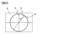
方位角φについて図を用いて説明する。図6は本発明の積層体やフィルムの上面図である。ここで図中4はフィルム面内で任意に選択した方位角0°の方向であり、図中5は方位角0°を基準に右回り(時計回り)に回転させた方位角φ方向であり、図中6が方位角φである。 The azimuth angle φ will be explained using a diagram. FIG. 6 is a top view of the laminate or film of the present invention. Here, 4 in the figure is the direction with an azimuth angle of 0° arbitrarily selected within the film plane, and 5 in the figure is the azimuth angle φ direction rotated clockwise (clockwise) based on the azimuth angle of 0°. , 6 in the figure is the azimuth angle φ.
そして本発明における方位角φn(n:1~5)とは、方位角φから設定される測定点であり、フィルムあるいは積層体の面内の任意の方位角0°を基準に右回り(時計回り)に22.5°ごとに設定した、0°、22.5°、45°、67.5°、90°の5点である。 The azimuth angle φ n (n: 1 to 5) in the present invention is a measurement point set from the azimuth angle φ, and is clockwise ( The points are 0°, 22.5°, 45°, 67.5°, and 90°, which are set every 22.5° (clockwise).
本発明の積層体は、方位角φn(n:1~5)において前記多層積層フィルムの表側の面の法線に対して20°、70°の角度で波長400~700nmのS波の光を入射したときのそれぞれの当該波長領域にわたる平均反射率をRs20(φn)、Rs70(φn)としたとき、少なくとも1つの方位角φnにおいて
Rs70(φn)-Rs20(φn)≧50(%) …(A)
を満足することが必要である。Rs70(φn)-Rs20(φn)の値は、ディスプレイ用途での集光性向上、ヘッドアップディスプレイやヘッドマウントディスプレイ用途での画像表示性向上、覗き見防止用途での視野角制御性向上、加飾フィルム用途での斜め方向での色調や光沢感の変化の大きさ向上といった目的では、60%以上、70%以上、80%以上、90%以上と高くなるほど好ましい。上記関係式(A)を満足することは入射したS波に対して干渉反射が発現していることを意味し、P波のみ干渉反射が発現していた従来品よりも斜め方向の光に対する反射性能が高いことを意味する。また、5点の方位角φnのうち2つ以上の方位角φnで上記関係式(A)を満足することが好ましく、上述した目的では3つ以上、4つ以上、さらには5つの点で上記関係式(A)を満足することが好ましい。上記関係式(A)を満足する方位角φnの点数が多いほど、S波の干渉反射が発現する方位角範囲が広いことを意味し、方位角依存性が小さいマルチアングル性を持つことを意味する。
The laminate of the present invention emits S-wave light with a wavelength of 400 to 700 nm at an angle of 20° and 70° to the normal to the front surface of the multilayer laminate film at an azimuth angle φ n (n: 1 to 5). When the average reflectance over the respective wavelength ranges when incident is Rs20 (φ n ) and Rs70 (φ n ), at least one azimuth angle φ n is Rs70 (φ n ) − Rs20 (φ n ) ≧ 50(%)...(A)
It is necessary to satisfy the following. The value of Rs70 (φ n ) - Rs20 (φ n ) improves light gathering performance in display applications, improves image display performance in head-up displays and head-mounted displays, and improves viewing angle control in applications to prevent prying eyes. For the purpose of improving the magnitude of change in color tone and glossiness in diagonal directions in decorative film applications, the higher the ratio is, the more preferable it is, such as 60% or more, 70% or more, 80% or more, or 90% or more. Satisfying the above relational expression (A) means that interference reflection occurs for the incident S wave, and the reflection for light in an oblique direction is higher than that of the conventional product in which interference reflection occurred only for the P wave. It means high performance. In addition, it is preferable that the above relational expression (A) is satisfied at two or more azimuth angles φ n out of the azimuth angles φ n of the five points, and for the above purpose, three or more, four or more, or even five points It is preferable that the above relational expression (A) be satisfied. The greater the number of azimuth angles φ n that satisfy the above relational expression (A), the wider the azimuth angle range in which S-wave interference reflection occurs, which indicates that the azimuth angle dependence is small and has multi-angle properties. means.
次に、前記多層積層フィルムの表側の面の法線に対して20°、40°、70°の角度で波長400~700nmのP波の光を入射したときのそれぞれの、当該波長領域および方位角φnのn:1~5にわたる平均反射率(%)をRp20、Rp40、Rp70と定義する。すなわち、Rp20、Rp40、Rp70は、ある方位角φnにおける波長400nm~700nmにわたる平均の反射率をさらに5点の方位角φn(n:1~5)で平均したものある。本発明の積層体は、
Rp20≦Rp40<Rp70 …(B)
を満足することが正面透過性を高め斜め反射性を向上させる観点から好ましい。斜め反射性向上の観点からRp70は30%以上であることが好ましく、より好ましくは40%以上、さらに好ましくは50%以上、ディスプレイ用途での集光性向上、ヘッドアップディスプレイやヘッドマウントディスプレイ用途での画像表示性向上、覗き見防止用途での視野角制御性向上、加飾フィルム用途での斜め方向での色調や光沢感の変化の大きさ向上といった目的では、60%以上、70%以上、80%以上と高くなるほど好ましい。
Next, when P-wave light with a wavelength of 400 to 700 nm is incident at angles of 20°, 40°, and 70° with respect to the normal to the front surface of the multilayer laminated film, the corresponding wavelength range and direction are determined. The average reflectance (%) over n: 1 to 5 of the angle φ n is defined as Rp20, Rp40, and Rp70. That is, Rp20, Rp40, and Rp70 are obtained by further averaging the average reflectance over a wavelength of 400 nm to 700 nm at a certain azimuth angle φ n at five azimuth angles φ n (n: 1 to 5). The laminate of the present invention is
Rp20≦Rp40<Rp70…(B)
It is preferable to satisfy the following from the viewpoint of increasing front transmittance and improving oblique reflectivity. From the viewpoint of improving diagonal reflectivity, Rp70 is preferably 30% or more, more preferably 40% or more, even more preferably 50% or more, improving light gathering performance in display applications, head-up displays and head-mounted displays. 60% or more, 70% or more, for the purpose of improving image display performance, improving viewing angle controllability in applications to prevent prying eyes, and improving the magnitude of changes in color tone and glossiness in diagonal directions in decorative film applications. The higher the ratio is, 80% or more, the more preferable it is.
また、斜め方向から視認した際に、鏡のように無色で光沢感のある外観を持たせたい場合は、フィルム面の法線に対して70°の角度で入射したときの波長400nm~700nmのP波の反射率から算出される色調C値が20以下であることが好ましく、より好ましくは15以下、さらに好ましくは10以下、さらに好ましくは5以下である。 In addition, if you want to have a mirror-like colorless and glossy appearance when viewed from an oblique direction, use a wavelength of 400 nm to 700 nm when incident at an angle of 70° to the normal to the film surface. The color tone C value calculated from the reflectance of P waves is preferably 20 or less, more preferably 15 or less, even more preferably 10 or less, and still more preferably 5 or less.
本発明の積層体は、方位角φnにおいて前記多層積層フィルムの表側の面の法線に対して70°の角度で波長240nm~2600nmのS波の光を入射したときの当該波長領域にわたる反射率のうち最大値をRs70(φn)MAX、最小値をRs70(φn)MINとしたとき、少なくとも1つの方位角φnにおいて
Rs70(φn)MAX-Rs70(φn)MIN≧20(%) …(C)
を満足することが好ましい。Rs70(φn)MAX-Rs70(φn)MINの値としては、より好ましくは30%以上、さらに好ましくは40%以上、特に好ましくは50%以上であり、ディスプレイ用途での集光性向上、ヘッドアップディスプレイやヘッドマウントディスプレイ用途での画像表示性向上、覗き見防止用途での視野角制御性向上、加飾フィルム用途での斜め方向での色調や光沢感の変化の大きさ向上といった目的では、60%以上、70%以上、80%以上、90%以上と高くなるほど好ましい。上記関係式(C)を満足することは入射したS波に対する干渉反射が発現していることを意味しP波のみ干渉反射が発現していた従来よりも斜め方向の光に対する反射性能が高いことを意味する。また、5点の方位角φnのうち2つ以上の方位角φnで上記関係式(C)を満足することが好ましく、上述した目的では3つ以上、4つ以上、さらには5つの点で上記関係式(C)を満足することが好ましい。上記関係式(C)を満足する方位角φnの点数が多いほど、S波の干渉反射が発現する方位角範囲が広いことを意味し、方位角依存性が小さいマルチアングル性を持つことを意味する。
In the laminate of the present invention, when S-wave light with a wavelength of 240 nm to 2600 nm is incident at an angle of 70° to the normal to the front surface of the multilayer laminate film at an azimuth angle φ n , the reflection over the wavelength range of 240 nm to 2600 nm is observed. When the maximum value of the rate is Rs70 (φ n ) MAX and the minimum value is Rs70 (φ n ) MIN, Rs70 (φ n ) MAX−Rs70 (φ n ) MIN≧20( %) ...(C)
It is preferable to satisfy the following. The value of Rs70 (φ n ) MAX - Rs70 (φ n ) MIN is more preferably 30% or more, even more preferably 40% or more, and particularly preferably 50% or more, which improves light collection in display applications, For purposes such as improving image display performance in head-up displays and head-mounted displays, improving viewing angle control in applications to prevent prying eyes, and improving the magnitude of changes in color tone and gloss in diagonal directions in decorative film applications. , 60% or more, 70% or more, 80% or more, 90% or more, the more preferable. Satisfying the above relational expression (C) means that interference reflection occurs for the incident S wave, and the reflection performance for oblique light is higher than in the past, where interference reflection occurred only for the P wave. means. In addition, it is preferable that the above relational expression (C) is satisfied at two or more azimuth angles φ n out of the azimuth angles φ n of the five points, and for the above purpose, three or more, four or more, or even five points It is preferable that the above relational expression (C) be satisfied. The greater the number of azimuth angles φ n that satisfy the above relational expression (C), the wider the azimuth angle range in which interference reflection of S waves occurs, indicating that the azimuth angle dependence is small and multi-angle properties are obtained. means.
以下に本発明の積層体が有する多層積層フィルムの一例を示すが、本発明の積層体が有する多層積層フィルムはかかる例に限定して解釈されるものではない。 An example of a multilayer laminate film included in the laminate of the present invention is shown below, but the multilayer laminate film included in the laminate of the present invention is not interpreted as being limited to such examples.
本発明の積層体が有する多層積層フィルムは異なる複数の熱可塑性樹脂が交互に11層以上積層した多層積層フィルムである。その積層構成は、熱可塑性樹脂Aを用いてなる層(A層)と熱可塑性樹脂Aとは異なる熱可塑性樹脂Bを用いてなる層(B層)とが交互に11層以上積層(A/B/A/B・・)されてなる多層積層フィルムや、A層とB層と熱可塑性樹脂Aおよび熱可塑性樹脂Bとは異なる熱可塑性樹脂Cを用いてなる層(C層)とが交互に11層以上積層されてなる多層積層フィルム、例えば、A/B/C/A/B/C・・・のようにA/B/Cユニットが交互に積層されていたり、A/C/B/C/A/C/B/C・・・のようにA/CユニットとB/Cユニットが交互に積層されてなる多層積層フィルム、が好ましい。 The multilayer laminate film included in the laminate of the present invention is a multilayer laminate film in which 11 or more layers of different thermoplastic resins are alternately laminated. The laminated structure consists of 11 or more layers (A/ B/A/B...), or a layer (C layer) made of a layer A, a layer B, and a thermoplastic resin C different from thermoplastic resin A and thermoplastic resin B (layer C). A multilayer laminated film formed by laminating 11 or more layers, for example, A/B/C units are laminated alternately like A/B/C/A/B/C..., or A/C/B A multilayer laminated film in which A/C units and B/C units are alternately laminated like /C/A/C/B/C... is preferred.
ここでいう熱可塑性樹脂A、B、Cが互いに「異なる」とは、結晶性・非晶性、光学的性質、熱的性質のいずれかが異なることをいう。光学的性質が異なるとは、屈折率が0.01以上異なることを言い、熱的性質が異なるとは、融点あるいはガラス転移温度が1℃以上異なっていることを言う。なお、一方の樹脂が融点を有しており、もう一方の樹脂が融点を有していない場合や、一方の樹脂が結晶化温度を有しており、もう一方の樹脂が結晶化温度を有していない場合も、異なる熱的性質を有することを意味する。異なる性質を持つ熱可塑性樹脂を積層することで、それぞれの熱可塑性樹脂の単一の層のフィルムではなし得ない機能をフィルムに与えることができる。 Here, the term "thermoplastic resins A, B, and C" being "different" from each other means that they differ in any of crystallinity/amorphism, optical properties, and thermal properties. Different optical properties mean a difference in refractive index of 0.01 or more, and different thermal properties mean a difference of 1° C. or more in melting point or glass transition temperature. Note that one resin has a melting point and the other does not, or one resin has a crystallization temperature and the other resin has a crystallization temperature. If not, it also means that they have different thermal properties. By laminating thermoplastic resins with different properties, it is possible to provide the film with functions that cannot be achieved with a single layer of each thermoplastic resin.
本発明の積層体が有する多層積層フィルムに用いられる熱可塑性樹脂としては、例えば、ポリエチレン、ポリプロピレン、ポリ(4-メチルペンテン-1)などのポリオレフィン、シクロオレフィンとしては、ノルボルネン類の開環メタセシス重合,付加重合,他のオレフィン類との付加共重合体である脂環族ポリオレフィン、ポリ乳酸、ポリブチルサクシネートなどの生分解性ポリマー、ナイロン6、ナイロン11、ナイロン12、ナイロン66などのポリアミド、アラミド、ポリメチルメタクリレート、ポリ塩化ビニル、ポリ塩化ビニリデン、ポリビニルアルコール、ポリビニルブチラール、エチレン酢酸ビニルコポリマー、ポリアセタール、ポリグルコール酸、ポリスチレン、スチレン共重合ポリメタクリル酸メチル、ポリカーボネート、ポリプロピレンテレフタレート、ポリエチレンテレフタレート、ポリブチレンテレフタレート、ポリエチレン-2,6-ナフタレートなどのポリエステル、ポリエーテルサルフォン、ポリエーテルエーテルケトン、変性ポリフェニレンエーテル、ポリフェニレンサルファイド、ポリエーテルイミド、ポリイミド、ポリアリレート、4フッ化エチレン樹脂、3フッ化エチレン樹脂、3フッ化塩化エチレン樹脂、4フッ化エチレン-6フッ化プロピレン共重合体、ポリフッ化ビニリデンなどが挙げられる。これらの中で、強度・耐熱性・透明性の観点から、特にポリエステルを用いることが好ましく、ポリエステルとしては芳香族ジカルボン酸または脂肪族ジカルボン酸とジオールを主たる構成成分とする単量体からの重合により得られるポリエステルが好ましい。
Examples of thermoplastic resins used in the multilayer laminate film of the laminate of the present invention include polyolefins such as polyethylene, polypropylene, and poly(4-methylpentene-1), and examples of cycloolefins include ring-opening metathesis polymerization of norbornenes. , addition polymerization, alicyclic polyolefins that are addition copolymers with other olefins, biodegradable polymers such as polylactic acid and polybutyl succinate, polyamides such as
ここで、芳香族ジカルボン酸として、例えば、テレフタル酸、イソフタル酸、フタル酸、1,4-ナフタレンジカルボン酸、1,5-ナフタレンジカルボン酸、2,6-ナフタレンジカルボン酸、4,4′-ジフェニルジカルボン酸、4,4′-ジフェニルエーテルジカルボン酸、4,4′-ジフェニルスルホンジカルボン酸などを挙げることができる。脂肪族ジカルボン酸としては、例えば、アジピン酸、スベリン酸、セバシン酸、ダイマー酸、ドデカンジオン酸、シクロヘキサンジカルボン酸とそれらのエステル誘導体などが挙げられる。中でも好ましくはテレフタル酸と2,6-ナフタレンジカルボン酸を挙げることができる。これらの酸成分は1種のみ用いてもよく、2種以上併用してもよく、さらには、ヒドロキシ安息香酸等のオキシ酸などを一部共重合してもよい。 Here, examples of aromatic dicarboxylic acids include terephthalic acid, isophthalic acid, phthalic acid, 1,4-naphthalenedicarboxylic acid, 1,5-naphthalenedicarboxylic acid, 2,6-naphthalenedicarboxylic acid, 4,4'-diphenyl Examples include dicarboxylic acid, 4,4'-diphenyl ether dicarboxylic acid, and 4,4'-diphenylsulfone dicarboxylic acid. Examples of aliphatic dicarboxylic acids include adipic acid, suberic acid, sebacic acid, dimer acid, dodecanedioic acid, cyclohexanedicarboxylic acid, and ester derivatives thereof. Among them, terephthalic acid and 2,6-naphthalene dicarboxylic acid are preferred. These acid components may be used alone or in combination of two or more, and furthermore, oxyacids such as hydroxybenzoic acid may be partially copolymerized.
また、ジオール成分としては、例えば、エチレングリコール、1,2-プロパンジオール、1,3-プロパンジオール、ネオペンチルグリコール、1,3-ブタンジオール、1,4-ブタンジオール、1,5-ペンタンジオール、1,6-ヘキサンジオール、1,2-シクロヘキサンジメタノール、1,3-シクロヘキサンジメタノール、1,4-シクロヘキサンジメタノール、ジエチレングリコール、トリエチレングリコール、ポリアルキレングリコール、2,2-ビス(4-ヒドロキシエトキシフェニル)プロパン、イソソルベート、スピログリコール、などを挙げることができる。中でもエチレングリコールが好ましく用いられる。これらのジオール成分は1種のみ用いてもよく、2種以上併用してもよい。 In addition, examples of diol components include ethylene glycol, 1,2-propanediol, 1,3-propanediol, neopentyl glycol, 1,3-butanediol, 1,4-butanediol, and 1,5-pentanediol. , 1,6-hexanediol, 1,2-cyclohexanedimethanol, 1,3-cyclohexanedimethanol, 1,4-cyclohexanedimethanol, diethylene glycol, triethylene glycol, polyalkylene glycol, 2,2-bis(4- Examples include hydroxyethoxyphenyl)propane, isosorbate, spiroglycol, and the like. Among them, ethylene glycol is preferably used. These diol components may be used alone or in combination of two or more.
上記ポリエステルのうち、ポリエチレンテレフタレートおよびその共重合体、ポリエチレンナフタレートおよびその共重合体、ポリブチレンテレフタレートおよびその共重合体、ポリブチレンナフタレートおよびその共重合体、さらにはポリヘキサメチレンテレフタレートおよびその共重合体ならびにポリヘキサメチレンナフタレートおよびその共重合体の中から選択されるポリエステルを用いることが好ましい。 Among the above polyesters, polyethylene terephthalate and its copolymers, polyethylene naphthalate and its copolymers, polybutylene terephthalate and its copolymers, polybutylene naphthalate and its copolymers, and even polyhexamethylene terephthalate and its copolymers. Preference is given to using polyesters selected among polymers and polyhexamethylene naphthalate and copolymers thereof.
また、本発明の積層体が有する多層積層フィルムが前述の多層積層フィルム構成であるとき、用いられる異なる性質を有する熱可塑性樹脂の好ましい組み合わせとしては、各熱可塑性樹脂のガラス転移温度の差の絶対値が20℃以下であることが好ましい。ガラス転移温度の差の絶対値を20℃以下とすることで、多層積層フィルムを製造する際の延伸不良を抑えることができる。 Further, when the multilayer laminate film of the laminate of the present invention has the above-mentioned multilayer laminate film configuration, a preferable combination of thermoplastic resins having different properties to be used is the absolute difference in glass transition temperature of each thermoplastic resin. Preferably, the value is 20°C or less. By setting the absolute value of the difference in glass transition temperature to 20° C. or less, poor stretching during production of a multilayer laminated film can be suppressed.
本発明の積層体が有する多層積層フィルムが前述の多層積層フィルム構成であるとき、用いられる異なる性質を有する熱可塑性樹脂の好ましい組み合わせとしては、各熱可塑性樹脂のSP値(溶解性パラメータともいう)の差の絶対値が、1.0以下であることが好ましい。SP値の差の絶対値が1.0以下であると層間剥離が生じにくくなる。 When the multilayer laminate film of the laminate of the present invention has the above-mentioned multilayer laminate film configuration, a preferable combination of thermoplastic resins having different properties used is the SP value (also referred to as solubility parameter) of each thermoplastic resin. It is preferable that the absolute value of the difference is 1.0 or less. When the absolute value of the difference in SP value is 1.0 or less, delamination is less likely to occur.
また、異なる性質を有するポリマーは同一の基本骨格を供えた組み合わせからなることが好ましい。ここでいう基本骨格とは、樹脂を構成する繰り返し単位のことであり、たとえば、一方の熱可塑性樹脂としてポリエチレンテレフタレートを用いる場合は、高精度な積層構造が実現しやすい観点から、他方の熱可塑性樹脂として、ポリエチレンテレフタレートと同一の基本骨格であるエチレンテレフタレートを含むことが好ましい。異なる光学的性質を有するポリエステル樹脂同士を同一の基本骨格を含む樹脂同士とすることで、積層精度を高くし、さらに積層界面での層間剥離を抑えることができる。 Further, it is preferable that polymers having different properties are combined with the same basic skeleton. The basic skeleton here refers to the repeating units that make up the resin. For example, when using polyethylene terephthalate as one thermoplastic resin, from the perspective of easily realizing a highly precise laminated structure, It is preferable that the resin contains ethylene terephthalate, which has the same basic skeleton as polyethylene terephthalate. By using polyester resins having different optical properties as resins containing the same basic skeleton, it is possible to increase lamination accuracy and further suppress delamination at the lamination interface.
同一の基本骨格を有し、かつ、異なる性質を具備させるには、共重合体とすることが望ましい。すなわち、例えば、一方の樹脂がポリエチレンテレフタレートの場合、他方の樹脂は、エチレンテレフタレート単位と他のエステル結合を持った繰り返し単位とで構成された樹脂を用いるような態様である。他の繰り返し単位を入れる割合(共重合量ということがある)としては、異なる性質を獲得する必要性から5%以上が好ましく、より好ましくは10%以上である。一方、層間の密着性や、熱流動特性の差が小さいため各層の厚みの精度や厚みの均一性を維持する上では、90%以下が好ましく、より好ましくは80%以下である。 In order to have the same basic skeleton and different properties, it is desirable to form a copolymer. That is, for example, when one resin is polyethylene terephthalate, the other resin is a resin composed of ethylene terephthalate units and other repeating units having ester bonds. The proportion of other repeating units (sometimes referred to as copolymerization amount) is preferably 5% or more, more preferably 10% or more, from the necessity of acquiring different properties. On the other hand, in order to maintain the precision and uniformity of the thickness of each layer because the difference in adhesion between layers and thermal fluid properties is small, the thickness is preferably 90% or less, more preferably 80% or less.
また、A層とB層はそれぞれ、複数種の熱可塑性樹脂がブレンドまたはアロイされ用いられることも望ましい。複数種の熱可塑性樹脂をブレンドまたはアロイさせることで、1種類の熱可塑性樹脂では得られない性能を得ることができる。 Further, it is also desirable that the A layer and the B layer each contain a blend or alloy of a plurality of types of thermoplastic resins. By blending or alloying multiple types of thermoplastic resins, performance that cannot be obtained with a single type of thermoplastic resin can be obtained.
本発明の積層体が有する多層積層フィルムが前述の多層積層フィルム構成であるとき、熱可塑性樹脂Aおよび/または熱可塑性樹脂Bがポリエステルであることが好ましく、熱可塑性樹脂Aがポリエチレンテレフタレートを主たる成分とし、熱可塑性系樹脂Bがジカルボン酸成分としてテレフタル酸、ジオール成分としてエチレングリコールを含んでなり、さらに、ジカルボン酸成分として、ナフタレンジカルボン酸、シクロヘキサンジカルボン酸、ジオール成分としてシクロヘキサンジメタノール、スピログリコール、イソソルビドのうち少なくともいずれか1つの共重合成分を含んでなるポリエステルを主たる成分とすることも好ましい。なお、本発明において「主たる成分」とは、構成する樹脂全体の50質量%を超える成分を表す。 When the multilayer laminate film of the laminate of the present invention has the above-described multilayer laminate film configuration, it is preferable that thermoplastic resin A and/or thermoplastic resin B are polyester, and thermoplastic resin A has polyethylene terephthalate as its main component. The thermoplastic resin B contains terephthalic acid as a dicarboxylic acid component, ethylene glycol as a diol component, naphthalene dicarboxylic acid, cyclohexane dicarboxylic acid as a dicarboxylic acid component, cyclohexanedimethanol, spiroglycol, as a diol component, It is also preferred that the main component be a polyester containing at least one copolymer component of isosorbide. In the present invention, the term "main component" refers to a component that accounts for more than 50% by mass of the entire constituent resin.
本発明の積層体が有する多層積層フィルムは、隣接する層の面内屈折率差が小さく、面直屈折率の差が大きいことが好ましい。ここで、面内屈折率の差としては0.03以下であることが好ましく、より好ましくは0.02以下、さらに好ましくは0.01以下である。面直屈折率の差としては0.03より大きいことが好ましく、より好ましくは0.06以上、さらに好ましくは0.09以上、特に好ましくは0.12以上である。隣接する層がこのような面内屈折率差と面直屈折率差を持つことで、正面方向の光は反射せず透過し、斜め方向のP波の光を反射する特性を高めることができる。多層積層フィルムの各層の面内屈折率はフィルム面内の方位によって異なる屈折率を取り得る。層を構成する熱可塑性樹脂が非晶性樹脂であることや、結晶性樹脂であっても融点よりも10℃以上高い温度で熱処理を行った場合は、その層の屈折率は面内の測定方位や、面内・面直によらず一定の屈折率である等方性と見なすことができるが、結晶性樹脂であり融点以下の温度で熱処理を行った場合は、測定方位によって異なる面内屈折率を取り得る。この面内屈折率の測定方位でのムラは0.03以下であることが好ましくより好ましくは0.02以下、さらに好ましくは0.01以下である。面内屈折率の測定方位でのムラを小さくするには、多層積層フィルムの延伸が長手方向と幅方向に延伸する二軸延伸であって、延伸による長手方向と幅方向への熱可塑性樹脂の配向をバランス化することを採用することができる。面内屈折率の測定方位でのムラが小さくなると、本発明の積層体の各方位角における反射率のムラが小さくなる。
The multilayer laminate film included in the laminate of the present invention preferably has a small in-plane refractive index difference between adjacent layers and a large perpendicular refractive index difference. Here, the difference in in-plane refractive index is preferably 0.03 or less, more preferably 0.02 or less, still more preferably 0.01 or less. The difference in perpendicular refractive index is preferably larger than 0.03, more preferably 0.06 or more, still more preferably 0.09 or more, particularly preferably 0.12 or more. By having such an in-plane refractive index difference and perpendicular refractive index difference between adjacent layers, light in the front direction is transmitted without being reflected, and the property of reflecting P-wave light in an oblique direction can be enhanced. . The in-plane refractive index of each layer of a multilayer laminated film can take a different refractive index depending on the in-plane orientation of the film. If the thermoplastic resin constituting the layer is an amorphous resin, or even if it is a crystalline resin, if it is heat-treated at a
所望の波長範囲における反射率を調整する方法は、隣接する層の面直屈折率差、多層積層フィルムの積層数、各層の層厚み分布、製膜条件(例えば延伸倍率、延伸速度、延伸温度、熱処理温度、熱処理時間)の調整等が挙げられる。 The method of adjusting the reflectance in a desired wavelength range is based on the perpendicular refractive index difference between adjacent layers, the number of laminated layers of the multilayer laminated film, the layer thickness distribution of each layer, film forming conditions (e.g., stretching ratio, stretching speed, stretching temperature, Adjustment of heat treatment temperature, heat treatment time, etc.
A層とB層の2種交互積層の好ましい構成としては、A層が結晶性の熱可塑性樹脂を用いてなり、B層が非晶性の熱可塑性樹脂を主たる成分とする樹脂またはA層の熱可塑性樹脂の融点よりも15℃以上低い融点を持つ結晶性の熱可塑性樹脂を主たる成分とする樹脂を用いてなる組み合わせを挙げることができる。反射率が高くなり積層数が少なく済むことから、A層とB層の面直屈折率差は高い方が好ましく、積層数は101層以上が好ましく、より好ましくは401層以上、さらに好ましくは601層以上であり、積層装置の大型化の観点から上限としては5000層程度である。層厚み分布は隣接するA層とB層の光学厚みが下記(1)式を満たすことが好ましい。 A preferred structure of two types of alternately laminated layers A and B is that the A layer is made of a crystalline thermoplastic resin, and the B layer is made of a resin whose main component is an amorphous thermoplastic resin or the A layer is made of a resin whose main component is an amorphous thermoplastic resin. Examples include combinations using resins whose main component is a crystalline thermoplastic resin having a melting point 15° C. or more lower than the melting point of the thermoplastic resin. Since the reflectance is high and the number of laminated layers is small, it is preferable that the difference in perpendicular refractive index between layer A and layer B is high, and the number of laminated layers is preferably 101 or more, more preferably 401 or more, and even more preferably 601. layer or more, and from the viewpoint of increasing the size of the laminating device, the upper limit is about 5000 layers. Regarding the layer thickness distribution, it is preferable that the optical thicknesses of adjacent layers A and B satisfy the following formula (1).

ここでλは反射波長、nAはA層の面直屈折率、dAはA層の厚み、nBはB層の面直屈折率、dBはB層の厚みである。 Here, λ is the reflection wavelength, n A is the perpendicular refractive index of the A layer, d A is the thickness of the A layer, n B is the perpendicular refractive index of the B layer, and d B is the thickness of the B layer.
層厚みの分布はフィルム面の一方から反対側の面へ向かって一定の層厚み分布や、フィルム面の一方から反対側の面へ向かって増加または減少する層厚み分布や、フィルム面の一方からフィルム中心へ向かって層厚みが増加した後減少する層厚み分布や、フィルム面の一方からフィルム中心へ向かって層厚みが減少した後増加する層厚み分布等が好ましい。層厚み分布の設計としては、線形、等比、階差数列といった連続的に変化するものや、10層から50層程度の層がほぼ同じ層厚みを持ち、その層厚みがステップ状に変化するものが好ましい。 The layer thickness distribution may be a constant layer thickness distribution from one side of the film to the opposite side, a layer thickness distribution that increases or decreases from one side of the film to the opposite side, or a layer thickness distribution that increases or decreases from one side of the film to the other side. A layer thickness distribution in which the layer thickness increases and then decreases toward the center of the film, and a layer thickness distribution in which the layer thickness decreases and then increases from one side of the film toward the center of the film are preferred. Designs for layer thickness distribution include those that change continuously such as linear, geometric, and stepwise progressions, and those that have approximately the same layer thickness between 10 and 50 layers, and the layer thickness changes in a step-like manner. Preferably.
多層積層フィルムにおける両表層部には、保護層として層厚み3μm以上の層を設けることが好ましい。保護層の厚みは好ましくは5μm以上、より好ましくは10μm以上である。このように保護層の厚みを厚くとることで、製膜時の成形不良であるいわゆるフローマークの抑制、他のフィルムや成形体とのラミネート工程およびラミネート工程後における多層積層フィルム中の薄膜層の変形の抑制、耐押圧性の向上などの効果を得ることができる。 It is preferable to provide a layer having a layer thickness of 3 μm or more as a protective layer on both surface layer portions of the multilayer laminated film. The thickness of the protective layer is preferably 5 μm or more, more preferably 10 μm or more. By increasing the thickness of the protective layer in this way, it is possible to suppress so-called flow marks, which are molding defects during film production, and to reduce the thickness of thin film layers in multilayer laminated films during the lamination process with other films or molded bodies, and after the lamination process. Effects such as suppressing deformation and improving pressure resistance can be obtained.
本発明で用いる多層積層フィルムの厚みは、特に限られるものではないが、例えば20μm~300μmであることが好ましい。20μm以上とすることで、フィルムに腰を与えハンドリング性を向上させることができる。また、300μm以下とすることで、フィルムの腰が強すぎて成形性が悪くなるのを抑えることができる。 The thickness of the multilayer laminate film used in the present invention is not particularly limited, but is preferably, for example, 20 μm to 300 μm. By setting the thickness to 20 μm or more, it is possible to give stiffness to the film and improve handling properties. Further, by setting the thickness to 300 μm or less, it is possible to prevent the film from becoming too stiff and having poor moldability.
次に本発明の積層体がS波に対しても干渉反射を発現する原理について、本発明の積層体の一態様として、図7、図9の態様を挙げて説明する。図7、図9は本発明の積層体によるS波の干渉反射を説明する図であり積層体7の断面図である。10aは本発明の積層体に入射するP波を、11aは本発明の積層体に入射するS波を示す。なお、本発明の積層体によって干渉反射されなかった成分や表面反射される成分については図7、図9には記載していない。本発明の積層体に入射したP波10aは多層積層フィルム8aによって干渉反射される。なお、図には記載はしていないが、P波の反射率が100%でない場合は、入射したP波の一部は透過される。また、図には記載していないが、多層積層フィルムの表面でのP波の反射(表面反射)も発生している。一方、S波11aは干渉反射されずに多層積層フィルム8aを透過する。なお、図には記載はしていないが、入射したS波の一部は多層積層フィルムの表面で反射(表面反射)されている。
Next, the principle by which the laminate of the present invention exhibits interference reflection even for S-waves will be explained by citing the embodiments of FIGS. 7 and 9 as one embodiment of the laminate of the present invention. 7 and 9 are cross-sectional views of the
この多層積層フィルム8aを透過したS波11bは、図7においては、複屈折を有する層(以降、「複屈折層」と呼ぶ場合がある)9を通過することでP波12aに変換される。この変換によるP波12aを、入射方向から見て複屈折層9の奥側の多層積層フィルム8bにより干渉反射させることによって、本発明の積層体に入射したP波のみならずS波に対しても干渉反射を発現させている。つまり、図7の態様においては、多層積層フィルムが干渉反射を行っているのは実際にはP波に対してであるが、実質的には積層体に入射したP波とS波の両方が干渉反射に寄与している。
In FIG. 7, the
また、図9においては、S波11bが偏光解消層14を通過することで、P波15aとS波15bに変換される。この変換によるP波15bを、入射方向から見て偏光解消層14の奥側の多層積層フィルム8bにより干渉反射させることによって、本発明の積層体に入射したP波のみならずS波に対しても干渉反射を発現させている。つまり、図9の態様においては、多層積層フィルムが干渉反射を行っているのは実際にはP波に対してであるが、実質的には積層体に入射したP波とS波の一部の両方が干渉反射に寄与している。
Further, in FIG. 9, the
一方、図8は従来技術を用いた場合の一例として多層積層フィルム8a、8bを透明接着剤13で積層した積層体の断面図である。偏光を制御する機能を何ら有しない透明接着剤13を用いた場合は、多層積層フィルムを何枚積層しても積層体に入射したS波に由来する干渉反射は発現しない。
On the other hand, FIG. 8 is a cross-sectional view of a laminate in which
本発明の積層体は、前述の多層積層フィルムと複屈折層を有する積層体であることが好ましく、複屈折を有する層の両側に多層積層フィルムを有する構成、または、複屈折を有する層の両側に接着層を介して多層積層フィルムを有する構成であることが好ましい。多層積層フィルムと複屈折層を有する積層体の好ましい様態の一例として図7の積層体が挙げられる。 The laminate of the present invention is preferably a laminate having the above-mentioned multilayer laminate film and a birefringent layer, and has a structure in which the multilayer laminate film is on both sides of the layer having birefringence, or a structure in which the laminate has the multilayer laminate film on both sides of the layer having birefringence, or both sides of the layer having birefringence. It is preferable to have a multilayer laminated film with an adhesive layer interposed therebetween. A preferred example of a laminate having a multilayer laminate film and a birefringent layer is the laminate shown in FIG.
複屈折層は通過する光の偏光状態を変化させる特徴を有する。複屈折層の面内方向における主配向軸方位を0°としたとき、その主配向軸方位0°に対して偏光の振動方向の方位φが0°<φ<90°の範囲で複屈折層を偏光が通過すると、その偏光の偏光特性が変化する。つまりS波がその振動の方位角φSを0°<φS<90°として複屈折層を通過すると、その一部または全成分がP波に変換される。
A birefringent layer has the characteristic of changing the polarization state of light passing through it. When the main orientation axis direction in the in-plane direction of the birefringent layer is 0°, the birefringent layer is in the range where the orientation φ of the vibration direction of polarized light is 0°<φ<90° with respect to the main
複屈折層を通過することによるS波からP波への変換は、複屈折層の位相差(Re)と、複屈折層の面内方向における主配向軸方位と入射したS波の振動の方位がなす方位角(φS)によって決定される。 The conversion from S wave to P wave by passing through the birefringent layer depends on the phase difference (Re) of the birefringent layer, the main orientation axis direction in the in-plane direction of the birefringent layer, and the vibration direction of the incident S wave. is determined by the azimuth angle (φ S ) formed by
複屈折層の位相差は、波長590nmにおける位相差(Re(590))が100nm~500nmの範囲であることが好ましい。位相差の1/4の波長のS波をP波とS波に変換する効果を持つλ/4板としては、Re(590)がより好ましくは100nm~200nmの範囲、さらに好ましくは100nm~180nm(140±40nm)の範囲である。位相差の1/2の波長のS波をP波に変換する効果を持つλ/2板としては、Re(590)がより好ましくは200nm~400nmの範囲、さらに好ましくは200nm~360nmの範囲、さらに好ましくは240nm~320nm(280±40nm)の範囲である。 The retardation of the birefringent layer is preferably such that the retardation (Re(590)) at a wavelength of 590 nm is in the range of 100 nm to 500 nm. As a λ/4 plate having the effect of converting S waves with a wavelength of 1/4 of the phase difference into P waves and S waves, Re (590) is more preferably in the range of 100 nm to 200 nm, and even more preferably in the range of 100 nm to 180 nm. (140±40 nm). As a λ/2 plate having the effect of converting S waves with a wavelength of 1/2 of the phase difference into P waves, Re (590) is more preferably in the range of 200 nm to 400 nm, and even more preferably in the range of 200 nm to 360 nm. More preferably, the range is 240 nm to 320 nm (280±40 nm).
位相差は複屈折×厚みで算出される。複屈折層の面内方向の複屈折は0.5×10⁻³以上であることが好ましく、より好ましくは1.0×10⁻³以上、さらに好ましくは3.0×10⁻³以上である。 The phase difference is calculated as birefringence x thickness. The in-plane birefringence of the birefringent layer is preferably 0.5×10 −3 or more, more preferably 1.0×10 −3 or more, and even more preferably 3.0×10 −3 or more. .
次に、位相差とS波の偏光変換の一例を説明する。Re(590)が280nmの複屈折層に対して、S波の振動の方位が複屈折層の主配向軸方位に対して方位角φS=45°で通過するとS波の振動の方位は90°変換されP波となる。また、Re(590)が140nmの複屈折層に対して、S波の振動の方位が複屈折層の主配向軸方位に対して方位角φS=45°で通過するとS波は1/2がP波に変換される。この変換効率は方位角φS=45°が最大であり45°から離れるにつれて効果が低くなるため、S波の振動方向の方位と複屈折層の配向軸の方位がなす角φSは0°<φS<90°、90°<φS<180°の範囲であることが好ましく、より好ましくは15°<φS<75°、105°<φS<165°の範囲であり、更に好ましくは30°<φS<60°、120°<φS<150°の範囲である。 Next, an example of phase difference and S-wave polarization conversion will be described. When the S wave vibration direction passes through a birefringent layer with Re(590) of 280 nm at an azimuth angle φ S =45° with respect to the main orientation axis direction of the birefringent layer, the S wave vibration direction is 90 nm. ° converted and becomes a P wave. Furthermore, when the S wave passes through a birefringent layer with Re(590) of 140 nm at an azimuth angle φ S =45° with respect to the main orientation axis direction of the birefringent layer, the S wave is 1/2 is converted into a P wave. This conversion efficiency is maximum at the azimuth angle φ S =45°, and the effect decreases as the distance from 45° increases. Therefore, the angle φ S formed by the azimuth of the vibration direction of the S wave and the azimuth of the orientation axis of the birefringent layer is 0°. <φ S <90°, 90°<φ S <180°, more preferably 15°<φ S <75°, 105°<φ S <165°, even more preferably is in the range of 30°<φ S <60°, 120°<φ S <150°.
本発明の積層体が有する複屈折層は熱可塑性樹脂または液晶を主たる成分とすることが好ましく、熱可塑性樹脂としてはポリビニルアルコール、ポリカーボネート、シクロオレフィン、ポリメチルメタクリレートのいずれかを主たる成分とすることが好ましい。これらの成分により位相差100nm~500nmを比較的容易に得ることができる。ポリビニルアルコール、ポリカーボネート、シクロオレフィン、ポリメチルメタクリレートはフィルムまたはシート状で少なくとも一方方向に延伸することで複屈折を持たせることが好ましく、液晶としては、アクリロイル基、メタクリロイル基、および、スチリル基等のエチレン性不飽和基、エポキシ基、および、オキセタン基等のカチオン性重合性基などが好ましい。液晶の形状としては、棒状、円盤状などが挙げられる。マトリクス中に液晶を分散させた後、基材や多層積層フィルムに塗布し一方方向に配向させることが好ましい。配向方法としては、ローラーを押し付けた後ローラーを回転させるラビング法や、紫外線や可視光線などの光を直線偏光で照射する光配向法などが挙げられる。 The birefringent layer included in the laminate of the present invention preferably contains a thermoplastic resin or liquid crystal as the main component, and the thermoplastic resin may contain polyvinyl alcohol, polycarbonate, cycloolefin, or polymethyl methacrylate as the main component. is preferred. With these components, a retardation of 100 nm to 500 nm can be obtained relatively easily. It is preferable that polyvinyl alcohol, polycarbonate, cycloolefin, and polymethyl methacrylate have birefringence by stretching them in at least one direction in the form of a film or sheet. Cationic polymerizable groups such as ethylenically unsaturated groups, epoxy groups, and oxetane groups are preferred. Examples of the shape of the liquid crystal include a rod shape and a disk shape. After dispersing the liquid crystal in a matrix, it is preferable to apply it to a base material or a multilayer laminated film and orient it in one direction. Examples of the alignment method include a rubbing method in which a roller is pressed and then rotated, and a photoalignment method in which linearly polarized light such as ultraviolet rays or visible light is irradiated.
本発明の積層体が有する複屈折層は一軸配向されていることが好ましい。一軸配向されていると入射角度や方位角に対する位相差の変化量が小さくなるため、入射角度や方位角に対するS波の偏光変換の依存性が小さくなり好ましい。 The birefringent layer included in the laminate of the present invention is preferably uniaxially oriented. Uniaxial alignment is preferable because the amount of change in phase difference with respect to the incident angle and azimuth angle is small, so that the dependence of polarization conversion of the S wave on the incident angle and azimuth angle is small.
本発明の積層体が有する複屈折層の厚みは特に限られるものではないが、例えば1μm~200μmであることが好ましい。複屈折層が熱可塑性樹脂を主たる成分とする場合は5μm~100μmであることがより好ましく、液晶を主たる成分とする場合は、1μm~20μmであることがより好ましい。 The thickness of the birefringent layer included in the laminate of the present invention is not particularly limited, but is preferably 1 μm to 200 μm, for example. When the birefringent layer has a thermoplastic resin as its main component, it is more preferably from 5 μm to 100 μm, and when it has liquid crystal as its main component, it is more preferably from 1 μm to 20 μm.
本発明の積層体は、多層積層フィルムと、液晶および/またはアスペクト比が1.5以上の粒子を含む、偏光解消効果を有する層(以降、「偏光解消層」と呼ぶ場合がある)を有する積層体であって、偏光解消層の両側に多層積層フィルムを有する構成、または、偏光解消層の両側に接着層を介して多層積層フィルムを有する構成であることも好ましい。偏光解消層は通過する直線偏光を楕円または円偏光に変換する効果があるため、S波が偏光解消層を通過するとS波とP波からなる楕円または円偏光に変換される。多層積層フィルムと偏光解消層を有する積層体の好ましい様態の一例として図9が挙げられる。 The laminate of the present invention has a multilayer laminate film and a layer having a depolarizing effect (hereinafter sometimes referred to as a "depolarizing layer") containing a liquid crystal and/or particles having an aspect ratio of 1.5 or more. It is also preferable that the laminate has a structure in which a multilayer laminate film is provided on both sides of a depolarization layer, or a structure in which a multilayer laminate film is provided on both sides of a depolarization layer via an adhesive layer. The depolarization layer has the effect of converting linearly polarized light passing therethrough into elliptically or circularly polarized light, so when S waves pass through the depolarizing layer, they are converted into elliptically or circularly polarized light consisting of S waves and P waves. FIG. 9 is an example of a preferred embodiment of a laminate having a multilayer laminate film and a depolarizing layer.
また、偏光解消層の例としては、液晶やアスペクト比が1.5以上の粒子(以降、「偏光解消材料」と呼ぶ場合がある)がマトリクス中に分散している構成が挙げられる。偏光解消材料は複屈折Δnが0.001以上であることが好ましい。また偏光解消材料のマトリクスにおける分散状態は、偏光解消材料の屈折率の高い方向と屈折率の低い方向がマトリクス中でランダム(整列していない)であることが好ましい。分散状態がランダムである結果、偏光解消層を通過する偏光に対して様々な位相差が生じることで偏光が解消される。 Furthermore, examples of the depolarization layer include a structure in which liquid crystals or particles having an aspect ratio of 1.5 or more (hereinafter sometimes referred to as "depolarization material") are dispersed in a matrix. The depolarizing material preferably has a birefringence Δn of 0.001 or more. Further, it is preferable that the dispersion state of the depolarizing material in the matrix is such that the direction of high refractive index and the direction of low refractive index of the depolarizing material are random (not aligned) in the matrix. As a result of the random dispersion state, various phase differences occur in the polarized light passing through the depolarization layer, thereby depolarizing the light.
ヘイズ低減の観点からマトリクスの屈折率は、偏光解消材料の平均屈折率に対して、その差が0.1以下となることが好ましい。マトリクス中における偏光解消材料の含有量は特に限られるものではないが、例えばマトリクスの全質量に対して、10~90質量%が好ましく、10~60質量%がより好ましく、さらに好ましくは10~40質量%である。偏光解消材料は1種類用いても2種類以上用いてもよい。 From the viewpoint of haze reduction, the difference between the refractive index of the matrix and the average refractive index of the depolarizing material is preferably 0.1 or less. The content of the depolarizing material in the matrix is not particularly limited, but is preferably 10 to 90% by mass, more preferably 10 to 60% by mass, even more preferably 10 to 40% by mass, based on the total mass of the matrix. Mass%. One type or two or more types of depolarization materials may be used.
偏光解消層に用いる液晶はその配向がランダムであるランダム液晶であることが好ましく、アスペクト比1.5以上の粒子は無機粒子であることが好ましい。 The liquid crystal used in the depolarization layer is preferably a random liquid crystal whose orientation is random, and the particles having an aspect ratio of 1.5 or more are preferably inorganic particles.
偏光解消層に用いる液晶としては、アクリロイル基、メタクリロイル基、および、スチリル基等のエチレン性不飽和基、エポキシ基、および、オキセタン基等のカチオン性重合性基などが好ましい。液晶の形状としては、棒状、円盤状などが挙げられる。またキラル剤を添加することも好ましい。キラル剤の含有量は特に限られるものではないが、例えばマトリクスの全質量に対して、0.1~10質量%が挙げられる。 Preferred liquid crystals used in the depolarization layer include ethylenically unsaturated groups such as acryloyl, methacryloyl, and styryl groups, epoxy groups, and cationic polymerizable groups such as oxetane groups. Examples of the shape of the liquid crystal include a rod shape and a disk shape. It is also preferable to add a chiral agent. The content of the chiral agent is not particularly limited, but may be, for example, 0.1 to 10% by mass based on the total mass of the matrix.
アスペクト比1.5以上の粒子としては、セルロース、ポリスチレン、アクリルや、シリカや、ストロンチウム、マグネシウム、カルシウムおよびその炭酸塩、酸化物や、チタン、ジルコニウム、ゲルマニウム、スズおよびその酸化物が挙げられる。その形状としては、針状、棒状、多角柱状、紡錘状などが挙げられる。粒子の大きさは短軸方向の長さが1nm以上、通常100μm以下、好ましくは1000nm以下であり、アスペクト比は2.0以上より好ましくは5.0以上、さらに好ましくは10以上であり、特に上限は設けないが製造限界などから1000程度である。 Examples of particles having an aspect ratio of 1.5 or more include cellulose, polystyrene, acrylic, silica, strontium, magnesium, calcium and carbonates and oxides thereof, titanium, zirconium, germanium, tin and oxides thereof. Its shape includes needle-like, rod-like, polygonal columnar, and spindle-like shapes. The particle size is such that the length in the minor axis direction is 1 nm or more, usually 100 μm or less, preferably 1000 nm or less, and the aspect ratio is 2.0 or more, preferably 5.0 or more, more preferably 10 or more, and especially Although there is no upper limit, it is approximately 1000 due to manufacturing limitations.
マトリクスとしては、樹脂は熱硬化性樹脂、熱可塑性樹脂などが挙げられ、熱硬化性樹脂はエポキシ、熱硬化性ポリイミド、フェノール、メラミン、ジアリルフタレート、シリコーン、ウレタンなどが、熱可塑性樹脂はオレフィン、アクリル、スチレン、ポリエステル、ポリアクリロニトリル、マレイミド、ポリ酢酸ビニル、エチレン・酢酸ビニル共重合体、ポリアミド、ポリ塩化ビニル、ポリアセタール、ポリフェニレンオキシド、ポリフェニレンスルフィド、ポリスルホン、ポリエーテルスルホン、ポリエーテルエーテルケトン、ポリアリルスルホン、ポリエーテルイミド、ポリメチルペンテン、フッ素、セルロースなどがあげられる。樹脂以外としては、ガラスなどが挙げられる。 Examples of the matrix include thermosetting resins and thermoplastic resins; thermosetting resins include epoxy, thermosetting polyimide, phenol, melamine, diallyl phthalate, silicone, and urethane; thermoplastic resins include olefin, Acrylic, styrene, polyester, polyacrylonitrile, maleimide, polyvinyl acetate, ethylene/vinyl acetate copolymer, polyamide, polyvinyl chloride, polyacetal, polyphenylene oxide, polyphenylene sulfide, polysulfone, polyether sulfone, polyether ether ketone, polyallyl Examples include sulfone, polyetherimide, polymethylpentene, fluorine, and cellulose. Examples of materials other than resin include glass.
偏光解消層の製造方法としては、マトリクス中に偏光解消材料を添加してフィルムまたはシート形状に製造することや、マトリクス中に分散させた後、基材や多層積層フィルムに塗布することが好ましい。 As a method for manufacturing the depolarizing layer, it is preferable to add the depolarizing material to a matrix and manufacture it in the form of a film or sheet, or to disperse it in the matrix and then apply it to a base material or a multilayer laminated film.
本発明の積層体は、前述の多層積層フィルムを少なくとも一方の表層に有することが好ましい。 The laminate of the present invention preferably has the above-described multilayer laminate film on at least one surface layer.
本発明の積層体および/または積層体が有する多層積層フィルムは、正面方向の透過率を高くするため、さらにその表面にプライマー層、ハードコート層、反射防止層(AR、AG)を有していてもよい。表面よりも屈折率の低い層を設けることでフィルム面に垂直に入射する光の透過率を高くすることができる。 The laminate and/or the multilayer laminate film of the present invention further has a primer layer, a hard coat layer, and an antireflection layer (AR, AG) on its surface in order to increase transmittance in the front direction. It's okay. By providing a layer having a lower refractive index than the surface, it is possible to increase the transmittance of light incident perpendicularly to the film surface.
本発明の積層体および/または積層体が有する多層積層フィルムは、さらにその表面に耐磨耗性層、傷防止層、色補正層、紫外線吸収層、光安定化層(HALS)、熱線吸収層、印刷層、ガスバリア層、粘着層などの機能性層を上記以外に有していても良い。これらの層は1層でも多層でも良く、また、1つの層に複数の機能を持たせても良い。また、多層積層フィルム中に、紫外線吸収剤、光安定化剤(HALS)、熱線吸収剤、結晶核剤、可塑剤などの添加剤を有していても良い。 The laminate of the present invention and/or the multilayer laminate film possessed by the laminate further includes an abrasion resistant layer, a scratch prevention layer, a color correction layer, an ultraviolet absorbing layer, a light stabilizing layer (HALS), and a heat ray absorbing layer on its surface. , a printed layer, a gas barrier layer, an adhesive layer, and other functional layers other than those described above. These layers may be one layer or multiple layers, and one layer may have multiple functions. Further, the multilayer laminated film may contain additives such as ultraviolet absorbers, light stabilizers (HALS), heat ray absorbers, crystal nucleating agents, and plasticizers.
本発明に含まれる多層積層フィルムを製造する具体的な態様の例を以下に記すが、本発明に含まれる多層積層フィルムはかかる例によって限定して解釈されるものではない。 Examples of specific aspects of manufacturing the multilayer laminate film included in the present invention are described below, but the multilayer laminate film included in the present invention is not to be interpreted as being limited by such examples.
本発明に含まれる多層積層フィルムの積層構成が、熱可塑性樹脂Aを用いてなる層(A層)と熱可塑性樹脂Aとは異なる熱可塑性樹脂Bを用いてなる層(B層)とが交互に11層以上積層(A/B/A/B・・)されてなる多層積層フィルムの場合、A層に対応する押出機AとB層に対応する押出機Bの2台から熱可塑性樹脂が供給され、それぞれの流路からのポリマーが積層される。 The laminated structure of the multilayer laminated film included in the present invention is such that a layer made of thermoplastic resin A (layer A) and a layer made of thermoplastic resin B different from thermoplastic resin A (layer B) are alternately formed. In the case of a multilayer laminated film in which 11 or more layers are laminated (A/B/A/B...), the thermoplastic resin is produced from two extruders: extruder A corresponding to layer A and extruder B corresponding to layer B. The polymers from each channel are stacked.
また、本発明に含まれる多層積層フィルムの積層構成が、A層と、B層と、熱可塑性樹脂A、熱可塑性樹脂Bとは異なる熱可塑性樹脂Cを用いてなる層(C層)とが交互に11層以上積層されてなる多層積層フィルム(例えば、A/B/C/A/B/C・・・のようにA/B/Cユニットが交互に積層されていたり、A/C/B/C/A/C/B/C・・・のようにA/CユニットとB/Cユニットが交互に積層されてなる多層積層フィルム)の場合、A層に対応する押出機AとB層に対応する押出機BとC層に対応する押出機Cの3台から熱可塑性樹脂が供給され、それぞれの流路からのポリマーが積層される。 Further, the laminated structure of the multilayer laminated film included in the present invention includes a layer A, a layer B, and a layer (C layer) using a thermoplastic resin C different from the thermoplastic resin A and the thermoplastic resin B. A multilayer laminated film formed by laminating 11 or more layers alternately (for example, A/B/C units are laminated alternately like A/B/C/A/B/C..., or A/C/ In the case of a multilayer laminated film in which A/C units and B/C units are alternately laminated like B/C/A/C/B/C..., extruders A and B corresponding to layer A are used. Thermoplastic resin is supplied from three extruders B corresponding to the layers and extruders C corresponding to the C layer, and the polymers from the respective flow paths are laminated.
また必要であれば、各熱可塑性樹脂を、押出機に投入する前に乾燥することも好ましい。 Furthermore, if necessary, it is also preferable to dry each thermoplastic resin before charging it into the extruder.
積層は、公知の積層装置であるマルチマニホールドタイプのフィードブロックとスクエアミキサーを用いる方法、もしくは、コームタイプのフィードブロックのみを用いることにより行うことができる。次いでその溶融体をT型口金等を用いてシート状に溶融押出し、その後、キャスティングドラム上で冷却固化して未延伸多層積層フィルムを得ることができる。積層精度を高める方法としては、特開2007-307893号公報、特許第4691910号公報、特許第4816419号公報に記載されている方法が好ましい。 Lamination can be performed by using a multi-manifold type feed block and a square mixer, which are known lamination devices, or by using only a comb type feed block. Next, the melt is extruded into a sheet using a T-shaped nozzle or the like, and then cooled and solidified on a casting drum to obtain an unstretched multilayer laminate film. As a method for increasing the lamination accuracy, methods described in Japanese Patent Application Publication No. 2007-307893, Japanese Patent No. 4691910, and Japanese Patent No. 4816419 are preferable.
続いて、この未延伸多層積層フィルムの延伸および熱処理を施す。延伸方法としては、公知の逐次二軸延伸法、もしくは同時二軸延伸法による二軸延伸を採用することが好ましい。延伸温度は、未延伸多層積層フィルムのガラス転移点温度以上、ガラス転移点温度+80℃以下の範囲にて行うことが好ましい。延伸倍率は、長手方向、幅方向それぞれ2倍~8倍の範囲が好ましく、より好ましくは3~6倍の範囲であり、長手方向と幅方向の延伸倍率差を小さくすることが好ましい。長手方向の延伸は、縦延伸機ロール間の速度変化を利用して延伸を行うことが好ましい。また、幅方向の延伸は、公知のテンター法を利用する。すなわち、フィルムの両端をクリップで把持しながら搬送して、フィルム両端のクリップ間隔を広げることで幅方向に延伸する。 Subsequently, this unstretched multilayer laminate film is stretched and heat treated. As the stretching method, it is preferable to employ biaxial stretching using a known sequential biaxial stretching method or a simultaneous biaxial stretching method. It is preferable that the stretching temperature be within the range of not less than the glass transition temperature of the unstretched multilayer laminate film and not more than +80°C of the glass transition temperature. The stretching ratio is preferably in the range of 2 to 8 times in the longitudinal direction and in the width direction, more preferably in the range of 3 to 6 times, and it is preferable to reduce the difference in the stretching ratio in the longitudinal direction and the width direction. It is preferable that the stretching in the longitudinal direction is carried out using speed changes between the rolls of the longitudinal stretching machine. Further, the stretching in the width direction utilizes a known tenter method. That is, the film is conveyed while gripping both ends with clips, and the film is stretched in the width direction by widening the gap between the clips at both ends of the film.
また、テンターでの延伸は同時二軸延伸を行うことも好ましい。同時二軸延伸を行なう場合について説明する。冷却ロール上にキャストされた未延伸フィルムを、同時二軸テンターへ導き、フィルムの両端をクリップで把持しながら搬送して、長手方向と幅方向に同時および/または段階的に延伸する。長手方向の延伸は、テンターのクリップ間の距離を広げることで、また、幅方向はクリップが走行するレールの間隔を広げることで達成される。本発明における延伸・熱処理を施すテンタークリップは、リニアモータ方式で駆動することが好ましい。その他、パンタグラフ方式、スクリュー方式などがあるが、中でもリニアモータ方式は、個々のクリップの自由度が高いため延伸倍率を自由に変更できる点で優れている。 Moreover, it is also preferable to carry out simultaneous biaxial stretching in a tenter. A case where simultaneous biaxial stretching is performed will be explained. The unstretched film cast on the cooling roll is introduced into a simultaneous biaxial tenter, and the film is conveyed while being held at both ends with clips, and stretched simultaneously and/or in stages in the longitudinal direction and the width direction. Stretching in the longitudinal direction is achieved by increasing the distance between the clips of the tenter, and in the width direction by increasing the distance between the rails on which the clips run. The tenter clip subjected to stretching and heat treatment in the present invention is preferably driven by a linear motor. Other methods include a pantograph method and a screw method, but among them, the linear motor method is superior in that the stretching ratio can be changed freely because each clip has a high degree of freedom.
延伸後に熱処理を行うことも好ましい。熱処理温度は、延伸温度以上、A層の熱可塑性樹脂の融点-10℃以下の範囲にて行うことが好ましく、熱処理後に熱処理温度-30℃以下の範囲にて冷却工程を経ることも好ましい。また、フィルムの熱収縮率を小さくするために、熱処理工程中または冷却工程中にフィルムを幅方向および/または長手方向に縮める(リラックス)ことも好ましい。リラックスの割合としては1%~10%の範囲が好ましく、より好ましくは1~5%の範囲である。 It is also preferable to perform heat treatment after stretching. The heat treatment temperature is preferably carried out in a range of not less than the stretching temperature and not more than -10°C, the melting point of the thermoplastic resin of layer A, and it is also preferable to carry out a cooling step after the heat treatment at a temperature not more than -30°C. Furthermore, in order to reduce the thermal shrinkage rate of the film, it is also preferable to shrink (relax) the film in the width direction and/or length direction during the heat treatment step or cooling step. The relaxation rate is preferably in the range of 1% to 10%, more preferably in the range of 1 to 5%.
最後に巻取り機にてフィルムを巻き取ることによって本発明の積層体が有する多層積層フィルムが製造される。 Finally, the multilayer laminate film included in the laminate of the present invention is manufactured by winding up the film with a winder.
本発明の積層体として、複屈折を有する層の両側に多層積層フィルムを有する構成、または、複屈折を有する層の両側に接着層を介して多層積層フィルムを有する構成の製造方法として具体的な態様の例を以下に記すが、本発明に含まれる積層体の製造方法はかかる例によって限定して解釈されるものではない。 The laminate of the present invention has a multilayer laminate film on both sides of a layer with birefringence, or a multilayer laminate film with an adhesive layer on both sides of a layer with birefringence. Examples of embodiments are described below, but the method for manufacturing a laminate included in the present invention is not interpreted as being limited by such examples.
(1-1)多層積層フィルムと複屈折層を直接または接着層を介して積層する製造方法を、好ましく採用することができる。
この場合、複屈折層はフィルムまたはシート状であることが好ましい。多層積層フィルムと複屈折層の密着力を向上させるため、多層積層フィルムと複屈折層それぞれ、または両方の密着面側にプライマー層を設けることも好ましい。積層方法としてはロールラミネートが好ましく、ラミネート時および/またはラミネート後に熱および/または紫外線を加えることも好ましい。
(1-1) A manufacturing method in which a multilayer laminated film and a birefringent layer are laminated directly or via an adhesive layer can be preferably employed.
In this case, the birefringent layer is preferably in the form of a film or sheet. In order to improve the adhesion between the multilayer laminate film and the birefringent layer, it is also preferable to provide a primer layer on the adhesion surface of each or both of the multilayer laminate film and the birefringent layer. Roll lamination is preferred as the lamination method, and it is also preferred to apply heat and/or ultraviolet rays during and/or after lamination.
(1-2)基材上に複屈折層を設けた後、複屈折層の基材を有していない側に多層積層フィルムを積層した後、基材を剥離し、その後、複屈折層の基材を剥離した側に別の多層積層フィルムを積層する製造方法も、好ましく採用することができる。
基材としてはポリマーフィルム、ガラスなどが挙げられ、ポリオレフィンフィルム、ポリエステルフィルムが好ましい。基材と複屈折層とが剥離し易いように、基材と複屈折層との間に離型層を設けることも好ましい。また、多層積層フィルムと複屈折層の密着力を向上させるため、多層積層フィルムの複屈折層との密着面側にプライマー層を設けることも好ましい。特に、基材と複屈折層の密着力が多層積層フィルムと複屈折層の密着力よりも小さくなるように、離型層やプライマー層を設計することが好ましい。また、多層積層フィルムと複屈折層との間に接着層を用いて積層することも好ましい。積層方法としてはロールラミネートが好ましく、ラミネート時および/またはラミネート後に熱および/または紫外線を加えることも好ましい。
(1-2) After providing a birefringent layer on the base material, a multilayer laminated film is laminated on the side of the birefringent layer that does not have the base material, and then the base material is peeled off. A manufacturing method in which another multilayer laminated film is laminated on the side from which the base material has been peeled can also be preferably employed.
Examples of the base material include polymer films and glass, with polyolefin films and polyester films being preferred. It is also preferable to provide a release layer between the base material and the birefringent layer so that the base material and the birefringent layer can be easily separated. Furthermore, in order to improve the adhesion between the multilayer laminate film and the birefringent layer, it is also preferable to provide a primer layer on the side of the multilayer laminate film that is in close contact with the birefringent layer. In particular, it is preferable to design the release layer and the primer layer so that the adhesive force between the base material and the birefringent layer is smaller than the adhesive force between the multilayer laminate film and the birefringent layer. It is also preferable to laminate the multilayer laminate film and the birefringent layer using an adhesive layer. Roll lamination is preferred as the lamination method, and it is also preferred to apply heat and/or ultraviolet rays during and/or after lamination.
(1-3)複屈折層の片側あるいは両側に多層積層フィルムを積層した後、少なくとも一方向に延伸する工程を有する製造方法も、好ましく採用することができる。
多層積層フィルムと複屈折層の密着力を向上させるため、多層積層フィルムと複屈折層のいずれか、または両方の密着面側にプライマー層を設けることも好ましい。また、多層積層フィルムと複屈折層との間に接着層を用いて積層することも好ましい。積層方法としてはロールラミネートが好ましく、ラミネート時および/またはラミネート後に熱および/または紫外線を加えることも好ましい。延伸方法はロール間の速度変化を利用して延伸を行うことやテンターを用いることが好ましく、延伸方向は長手方向や幅方向への延伸または、斜め方向への延伸などが好ましく、延伸温度は多層積層フィルムおよび/または複屈折を有する層のガラス転移点温度以上、ガラス転移点温度+80℃以下の範囲が好ましく、延伸倍率は1倍より大きく8倍以下が好ましい。
(1-3) A manufacturing method including a step of laminating a multilayer laminated film on one or both sides of the birefringent layer and then stretching the film in at least one direction can also be preferably employed.
In order to improve the adhesion between the multilayer laminate film and the birefringent layer, it is also preferable to provide a primer layer on the adhesion surface of either or both of the multilayer laminate film and the birefringent layer. It is also preferable to laminate the multilayer laminate film and the birefringent layer using an adhesive layer. Roll lamination is preferred as the lamination method, and it is also preferred to apply heat and/or ultraviolet rays during and/or after lamination. As for the stretching method, it is preferable to use speed changes between rolls or a tenter, and the stretching direction is preferably longitudinal direction, width direction stretching, or diagonal direction stretching. The range is preferably higher than the glass transition temperature of the laminated film and/or the layer having birefringence and lower than the glass transition temperature +80°C, and the stretching ratio is preferably greater than 1 times and less than 8 times.
(1-4)多層積層フィルム上に、複屈折層を構成する成分を含む塗液を塗布する工程を含む製造方法も、好ましく採用することができる。
多層積層フィルムと複屈折層の密着力を向上させるため、多層積層フィルムの複屈折層との密着面側にプライマー層を設けることも好ましい。塗布方法としては、バーコート、グラビアコート、ダイコートなどが挙げられる。多層積層フィルム上に、複屈折層を構成する成分を含む塗液を塗布した直後または、多層積層フィルム上に、当該塗液を塗布した後に、複屈折層の多層積層フィルムと積層していない側に別の多層積層フィルムを積層後に、熱および/または紫外線を加えることも好ましい。
(1-4) A manufacturing method including a step of applying a coating liquid containing a component constituting a birefringent layer onto a multilayer laminated film can also be preferably employed.
In order to improve the adhesion between the multilayer laminate film and the birefringent layer, it is also preferable to provide a primer layer on the side of the multilayer laminate film that is in close contact with the birefringent layer. Application methods include bar coating, gravure coating, die coating, and the like. Immediately after applying a coating liquid containing the components constituting the birefringent layer on the multilayer laminated film, or after applying the coating liquid on the multilayer laminated film, the side of the birefringent layer that is not laminated with the multilayer laminated film. It is also preferable to apply heat and/or ultraviolet rays after laminating another multilayer laminated film on the laminate.
次に、本発明の積層体として、偏光解消層の両側に多層積層フィルムを有する構成、または、偏光解消層の両側に接着層を介して多層積層フィルムを有する構成の製造方法として具体的な態様の例を以下に記すが、本発明に含まれる積層体の製造方法はかかる例によって限定して解釈されるものではない。 Next, we will discuss specific aspects of the method for manufacturing the laminate of the present invention having a multilayer laminate film on both sides of a depolarizing layer, or a structure having a multilayer laminate film on both sides of a depolarizing layer via an adhesive layer. Examples will be described below, but the method for manufacturing a laminate included in the present invention is not to be interpreted as being limited by such examples.
(2-1)多層積層フィルムと偏光解消層を直接または接着層を介して積層する製造方法を、好ましく採用することができる。
この場合、偏光解消層はフィルムまたはシート状であることが好ましい。
多層積層フィルムと偏光解消層の密着力を向上させるため、多層積層フィルムと偏光解消層それぞれ、または両方の密着面側にプライマー層を設けることも好ましい。積層方法としてはロールラミネートが好ましく、ラミネート時および/またはラミネート後に熱および/または紫外線を加えることも好ましい。
(2-1) A manufacturing method in which a multilayer laminated film and a depolarizing layer are laminated directly or via an adhesive layer can be preferably employed.
In this case, the depolarizing layer is preferably in the form of a film or sheet.
In order to improve the adhesion between the multilayer laminate film and the depolarizing layer, it is also preferable to provide a primer layer on the adhesion side of each or both of the multilayer laminate film and the depolarizing layer. Roll lamination is preferred as the lamination method, and it is also preferred to apply heat and/or ultraviolet rays during and/or after lamination.
(2-2)基材上に偏光解消層を設けた後、偏光解消層の基材を有していない側に多層積層フィルムを積層した後、基材を剥離し、その後、偏光解消層の基材を剥離した側に別の多層積層フィルムを積層する製造方法も、好ましく採用することができる。
基材としてはポリマーフィルム、ガラスなどが挙げられ、ポリオレフィンフィルム、ポリエステルフィルムが好ましい。基材と偏光解消層が剥離し易いように、基材と複屈折を有する層との間に離型層を設けることも好ましい。また、多層積層フィルムと偏光解消層の密着力を向上させるため、多層積層フィルムの偏光解消層との密着面側にプライマー層を設けることも好ましい。特に、基材と偏光解消層の密着力が多層積層フィルムと偏光解消層の密着力よりも小さくなるように、離型層やプライマー層を設計することが好ましい。また、多層積層フィルムと偏光解消層との間に接着層を用いて積層することも好ましい。積層方法としてはロールラミネートが好ましく、ラミネート時および/またはラミネート後に熱および/または紫外線を加えることも好ましい。
(2-2) After providing a depolarizing layer on the base material, a multilayer laminated film is laminated on the side of the depolarizing layer that does not have the base material, and then the base material is peeled off. A manufacturing method in which another multilayer laminated film is laminated on the side from which the base material has been peeled can also be preferably employed.
Examples of the base material include polymer films and glass, with polyolefin films and polyester films being preferred. It is also preferable to provide a release layer between the base material and the layer having birefringence so that the base material and the depolarizing layer can be easily peeled off. Furthermore, in order to improve the adhesion between the multilayer laminate film and the depolarizing layer, it is also preferable to provide a primer layer on the side of the multilayer laminate film that is in close contact with the depolarizing layer. In particular, it is preferable to design the release layer and the primer layer so that the adhesion between the base material and the depolarization layer is smaller than the adhesion between the multilayer laminate film and the depolarization layer. It is also preferable to laminate the multilayer laminate film and the depolarizing layer using an adhesive layer. Roll lamination is preferred as the lamination method, and it is also preferred to apply heat and/or ultraviolet rays during and/or after lamination.
(2-3)複屈折を有する層の片側あるいは両側に多層積層フィルムを積層した後、少なくとも一方向に延伸する工程を有する製造方法も、好ましく採用することができる。
多層積層フィルムと偏光解消層の密着力を向上させるため、多層積層フィルムと偏光解消層のいずれか、または両方の密着面側にプライマー層を設けることも好ましい。また、多層積層フィルムと偏光解消層との間に接着層を用いて積層することも好ましい。積層方法としてはロールラミネートが好ましく、ラミネート時および/またはラミネート後に熱および/または紫外線を加えることも好ましい。延伸方法はロール間の速度変化を利用して延伸を行うことやテンターを用いることが好ましく、延伸方向は長手方向や幅方向への延伸または、斜め方向への延伸などが好ましく、延伸温度は多層積層フィルムおよび/または複屈折を有する層のガラス転移点温度以上、ガラス転移点温度+80℃以下の範囲が好ましく、延伸倍率は1倍より大きく8倍以下が好ましい。但し、偏光解消材料の屈折率の高い方向と屈折率の低い方向がマトリクス中でランダム(整列していない)であることが好ましい観点から、偏光解消材料の配向を抑えた延伸条件であることが好ましい。
(2-3) A manufacturing method including a step of laminating a multilayer laminated film on one or both sides of a layer having birefringence and then stretching the film in at least one direction can also be preferably employed.
In order to improve the adhesion between the multilayer laminate film and the depolarizing layer, it is also preferable to provide a primer layer on the adhesion side of either or both of the multilayer laminate film and the depolarizing layer. It is also preferable to laminate the multilayer laminate film and the depolarizing layer using an adhesive layer. Roll lamination is preferred as the lamination method, and it is also preferred to apply heat and/or ultraviolet rays during and/or after lamination. As for the stretching method, it is preferable to use speed changes between rolls or a tenter, and the stretching direction is preferably longitudinal direction, width direction stretching, or diagonal direction stretching. The range is preferably higher than the glass transition temperature of the laminated film and/or the layer having birefringence and lower than the glass transition temperature +80°C, and the stretching ratio is preferably greater than 1 times and less than 8 times. However, from the viewpoint that it is preferable that the direction of high refractive index and the direction of low refractive index of the depolarizing material are random (not aligned) in the matrix, it is preferable that the stretching conditions suppress the orientation of the depolarizing material. preferable.
(2-4)多層積層フィルム上に、偏光解消層を構成する成分を含む塗液を塗布する工程を含む製造方法も、好ましく採用することができる。
多層積層フィルムと偏光解消層の密着力を向上させるため、多層積層フィルムの偏光解消層との密着面側にプライマー層を設けることも好ましい。塗布方法としては、バーコート、グラビアコート、ダイコートなどが挙げられる。多層積層フィルム上に、偏光解消層を構成する成分を含む塗液を塗布した直後または、多層積層フィルム上に、当該塗液を塗布した後に、偏光解消層の多層積層フィルムと積層していない側に別の多層積層フィルムを積層後に、熱および/または紫外線を加えることも好ましい。
(2-4) A manufacturing method including a step of applying a coating liquid containing a component constituting a depolarizing layer onto a multilayer laminated film can also be preferably employed.
In order to improve the adhesion between the multilayer laminate film and the depolarizing layer, it is also preferable to provide a primer layer on the side of the multilayer laminate film that is in close contact with the depolarizing layer. Application methods include bar coating, gravure coating, die coating, and the like. Immediately after applying a coating liquid containing the components constituting the depolarizing layer on the multilayer laminated film, or after applying the coating liquid on the multilayer laminated film, the side of the depolarizing layer that is not laminated with the multilayer laminated film It is also preferable to apply heat and/or ultraviolet rays after laminating another multilayer laminated film on the laminate.
本発明の積層体は、正面方向の光を透過し、斜め方向の光を透過しない特性を有するため、特にディスプレイ関係の種々の用途に好適に用いることができる。 Since the laminate of the present invention has a characteristic of transmitting light in the front direction and not transmitting light in an oblique direction, it can be particularly suitably used for various display-related applications.
本発明の導光板ユニットは、導光板の出射面側に本発明の積層体を配してなることにより、優れた正面集光性を発揮することができる。導光板ユニットにおける本発明の積層体の位置関係としては、反射フィルム/導光板/本発明の積層体/拡散シート/プリズムシート、反射フィルム/導光板/拡散シート/本発明の積層体/プリズムシート、反射フィルム/導光板/拡散シート/プリズムシート/本発明の積層体といったように、導光板よりも出射面側に本発明の積層体を配して使用されることが好ましく、プリズムシートよりも射出光の出側に用いられることが好ましい。 The light guide plate unit of the present invention can exhibit excellent frontal light condensing properties by arranging the laminate of the present invention on the exit surface side of the light guide plate. The positional relationship of the laminate of the present invention in the light guide plate unit is reflective film/light guide plate/laminate of the present invention/diffusion sheet/prism sheet, reflective film/light guide plate/diffusion sheet/laminate of the present invention/prism sheet. , reflective film/light guide plate/diffusion sheet/prism sheet/laminate of the present invention. It is preferable to use it on the exit side of the emitted light.
また本発明の光源ユニットも、本発明の積層体あるいは本発明の導光板ユニットを用いてなることにより、正面集光性に優れる。光源ユニットとしては、本発明の導光板ユニットと光源を有する、エッジ型の光源ユニット(エッジ型バックライト)や、複数の光源が設置された基板の出射面側に本発明の積層体を配した直下型の光源ユニット(直下型バックライト)が好ましい。直下型における本発明の積層体の位置関係としては、反射フィルム/拡散板/本発明の積層体/プリズムシート、反射フィルム/拡散板/プリズムシート/本発明の積層体といったように、拡散板よりも出射面側に本発明の積層体を配することが好ましい。また、エアーギャップのある状態で設置するだけでなく、粘着剤や接着剤などで他の部材と貼り合わせて配することも好ましい。 Further, the light source unit of the present invention also has excellent frontal light condensing properties by using the laminate of the present invention or the light guide plate unit of the present invention. Examples of the light source unit include an edge-type light source unit (edge-type backlight) having the light guide plate unit of the present invention and a light source, and a laminate of the present invention arranged on the output surface side of a substrate on which a plurality of light sources are installed. A direct type light source unit (direct type backlight) is preferable. In the direct type, the positional relationship of the laminate of the present invention is as follows: reflective film/diffuser plate/laminate of the present invention/prism sheet, reflective film/diffuser plate/prism sheet/laminate of the present invention, etc. It is also preferable to arrange the laminate of the present invention on the output surface side. Further, it is preferable not only to install the device with an air gap, but also to attach it to other members using an adhesive or an adhesive.
本発明の導光板ユニットおよび本発明の直下型の光源ユニットに共通して、本発明の積層体によって出射光を集光させることが出来るため、プリズムシートは省略することもできる。反射フィルムは拡散反射や鏡面反射するフィルムが挙げられ、特に拡散反射性の高いものが好ましく、白色反射フィルムが好ましい。拡散フィルムやプリズムシートは1枚のみである必要はなく、2枚以上用いる構成も取り得る。 Common to the light guide plate unit of the present invention and the direct type light source unit of the present invention, the emitted light can be condensed by the laminate of the present invention, so the prism sheet can be omitted. Examples of the reflective film include films that perform diffuse reflection and specular reflection, and those with high diffuse reflection are particularly preferred, and white reflective films are preferred. It is not necessary to use only one diffusion film or prism sheet, and a configuration using two or more sheets is also possible.
光源としては、白色光源や赤色、青色、緑色の単色光源やそれらの単色光源を2種類組み合わせたものが挙げられ、その発光帯域は450nm~650nmの範囲を備えることが好ましい。また、光源の発光方式としては、LED(Light Emitting Diode)、CCFL(Cold Cathode Fluorescent Lamp)、有機ELなどが挙げられる。 Examples of the light source include a white light source, a red, blue, and green monochromatic light source, and a combination of two of these monochromatic light sources, and the emission band thereof is preferably in the range of 450 nm to 650 nm. Further, examples of the light emitting method of the light source include LED (Light Emitting Diode), CCFL (Cold Cathode Fluorescent Lamp), organic EL, and the like.
また本発明の表示装置は、本発明の光源ユニットの優れた正面集光性により、高コントラスト、高輝度を達成する。その表示装置としては液晶表示装置や有機EL(Electro-Luminescence)表示装置などを挙げることができる。 Further, the display device of the present invention achieves high contrast and high brightness due to the excellent frontal light focusing ability of the light source unit of the present invention. Examples of the display device include a liquid crystal display device and an organic EL (Electro-Luminescence) display device.
また本発明の積層体を用いてなる本発明の投影画像表示部材は、現実世界の映像情報は正面から見とおすことができ、仮想世界の映像情報や文字情報は斜めから投影することで表示させるといった、光反射の高い指向性による優れた視認効果を奏する。例えば、自動車のガラスやプロンプターに本発明の投影画像表示部材を用いることで、正面方向の透明性を維持しつつ情報を鮮明かつ再現性高く表示することが可能となる。 Furthermore, in the projection image display member of the present invention using the laminate of the present invention, video information of the real world can be seen from the front, and video information and text information of the virtual world can be displayed by projecting it from an angle. The high directivity of light reflection provides an excellent visual recognition effect. For example, by using the projection image display member of the present invention on automobile glass or teleprompters, it becomes possible to display information clearly and with high reproducibility while maintaining transparency in the front direction.
本発明の投影画像表示部材の構成の例としては、本発明の積層体が透明部材の少なくとも一方の面に積層されているものや、本発明の積層体が少なくとも2つの透明部材間に積層されているものなどを挙げることができる。次述する自動車のインターフェースの場合、本発明の積層体あるいは本発明の投影画像表示部材を自動車のガラスに接着剤を介して貼りあわせてもよいし、自動車に用いる合わせガラスの内部に挿入してもよい。また、本発明の積層体を透明基材と貼りあわせて本発明の投影画像表示部材とし、プロンプターとして用いてもよい。 Examples of the structure of the projection image display member of the present invention include one in which the laminate of the present invention is laminated on at least one surface of a transparent member, and one in which the laminate of the present invention is laminated between at least two transparent members. You can list things that you have. In the case of the following automobile interface, the laminate of the present invention or the projection image display member of the present invention may be attached to the glass of the automobile with an adhesive, or may be inserted into the inside of the laminated glass used for the automobile. Good too. Further, the laminate of the present invention may be laminated with a transparent base material to form a projection image display member of the present invention, and the laminate may be used as a teleprompter.
また、本発明の投影画像表示装置は、本発明の投影画像表示部材と、当該投影画像表示部材の表示面の法線に対して20°以上の角度をもって入射される光源を備えたことを特徴とする。より具体的な用途としては、自動車や航空機の操縦席のフロントガラス等を含むインターフェース、電子看板、ゲーム機器などに用いられるヘッドアップディスプレイ(HUD)やヘッドマウントディスプレイ(HMD)を挙げることができる。自動車のインターフェースに用いる場合は、自動車のガラス(フロントガラス、サイドガラス、リヤガラスなど)やフロントガラス近傍に設けられた透明基材からなるプロンプターに向けて小型投影基材から情報を投影して用いることができる。 Furthermore, the projection image display device of the present invention is characterized by comprising the projection image display member of the present invention and a light source that enters at an angle of 20° or more with respect to the normal to the display surface of the projection image display member. shall be. More specific applications include head-up displays (HUD) and head-mounted displays (HMD) used in interfaces such as windshields of cockpits of automobiles and aircraft, electronic signboards, game devices, and the like. When used as an automobile interface, information can be projected from a small projection substrate onto a teleprompter made of a transparent substrate installed on the automobile glass (windshield, side glass, rear glass, etc.) or near the windshield. can.
また本発明の表示画面用フィルターは、本発明の積層体を用いてなることを特徴とする。本発明の表示画面用フィルターは正面方向の透過性が高く、斜め方向の反射性が高いため、ディスプレイの表示画面に設置したときに、表示画面を正面から見たときには明瞭に画面の表示を見ることができるが横方向から見たときには画面の表示を見ることができないという、覗き見防止の効果を奏する。さらに、従来覗き見防止用途として用いられているルーバーフィルムは正面方向から見た場合に画面の明るさが暗くなってしまうという問題があったが、本発明の表示画面用フィルターは画面の明るさをほとんど損なわない。 Further, the display screen filter of the present invention is characterized by using the laminate of the present invention. The display screen filter of the present invention has high transparency in the front direction and high reflectivity in the diagonal direction, so when installed on the display screen of a display, the screen display can be seen clearly when the display screen is viewed from the front. However, when viewed from the side, the display on the screen cannot be seen, which has the effect of preventing prying eyes. Furthermore, the louver film conventionally used to prevent prying eyes had a problem in that the brightness of the screen became dark when viewed from the front, but the display screen filter of the present invention reduces the brightness of the screen. almost no damage.
また、本発明の積層体は、表示装置の完成品として、表示装置の表示画面に貼り付けられていてもよいし、画面を構成する部材の内部に組み込まれていてもよい。すなわち、本発明の積層体を画像表示部に用いてなることを特徴とする表示装置もまた、本発明の表示装置である。この場合の本発明の表示装置の具体的な態様としては、本発明の積層体を液晶セルの前面に配してなる液晶表示装置や、本発明の積層体を発光層の前面に配してなる有機EL表示装置などを挙げることができる。 Further, the laminate of the present invention may be attached to the display screen of the display device as a finished product of the display device, or may be incorporated inside a member that constitutes the screen. That is, a display device characterized by using the laminate of the present invention in an image display section is also a display device of the present invention. In this case, specific embodiments of the display device of the present invention include a liquid crystal display device in which the laminate of the present invention is disposed in front of a liquid crystal cell, and a display device in which the laminate of the present invention is disposed in front of a light emitting layer. Examples include organic EL display devices.
また、本発明の積層体は、正面方向と斜め方向で色調および/または光沢感が変化する加飾フィルム用途などにも好適に用いることができる。 Further, the laminate of the present invention can be suitably used for decorative film applications in which the color tone and/or glossiness changes between the front direction and the oblique direction.
以下、本発明の積層体を具体的な実施例をあげて説明する。なお、以下に具体的に例示した熱可塑性樹脂以外の熱可塑性樹脂を用いた場合でも下記実施例を含めた本明細書の記載を参酌すれば、同様にして本発明の積層体を得ることができる。 Hereinafter, the laminate of the present invention will be explained by giving specific examples. Note that even when thermoplastic resins other than those specifically exemplified below are used, the laminate of the present invention can be obtained in the same manner by considering the description of this specification including the following examples. can.
[物性の測定方法ならびに効果の評価方法]
物性値の評価方法ならびに効果の評価方法は次の通りである。
[Method for measuring physical properties and evaluating effectiveness]
The methods for evaluating physical property values and effects are as follows.
(1)主配向軸方向
サンプルサイズを10cm×10cmとし、フィルム幅方向中央において、サンプルを切り出した。KSシステムズ(株)製(現王子計測機器(株))の分子配向計MOA-2001を用いて、主配向軸方向を求めた。
(1) Main orientation axis direction The sample size was 10 cm x 10 cm, and the sample was cut out at the center of the film width direction. The main orientation axis direction was determined using a molecular orientation meter MOA-2001 manufactured by KS Systems Co., Ltd. (currently Oji Scientific Instruments Co., Ltd.).
(2)透過率
日立製作所(株)製 分光光度計(U-4100 Spectrophotomater)の標準構成(固体測定システム)にて、入射角度θ=0°の角度で波長400~700nmの光を入射したときの透過率を1nm刻みで測定し、その平均透過率を求めた。測定条件としては、スリットは2nm(可視)、自動制御(赤外)とし、ゲインは2と設定し、走査速度を600nm/分とした。
(2) Transmittance When light with a wavelength of 400 to 700 nm is incident at an angle of incidence θ = 0° using the standard configuration (solid-state measurement system) of a spectrophotometer (U-4100 Spectrophotometer) manufactured by Hitachi, Ltd. The transmittance was measured in 1 nm increments, and the average transmittance was determined. The measurement conditions were a slit of 2 nm (visible), automatic control (infrared), a gain of 2, and a scanning speed of 600 nm/min.
(3)多層積層フィルムの反射率
日立製作所(株)製 分光光度計(U-4100 Spectrophotomater)に付属の角度可変反射ユニットとグランテーラ偏光子を取り付け、入射角度θ=20°、40°、70°の角度で波長400~700nmの範囲において1nm刻みでP波とS波の光を入射し、それぞれの反射率を測定した。得られた反射率から入射角度20°、40°、70°における波長400nm~700nmの範囲におけるP波に対する平均反射率としてRpf20、Rpf40、Rpf70を、S波に対する平均反射率としてRsf20、Rsf40、Rsf70を求めた。また、いずれの入射角における測定においても、入射光の方位φはフィルムの主配向軸に沿う方向とした。
(3) Reflectance of multilayer laminated film Attach the included variable angle reflection unit and GranTaylor polarizer to a spectrophotometer (U-4100 Spectrophotometer) manufactured by Hitachi, Ltd., and incident angle θ = 20°, 40°, 70°. P-wave and S-wave light was incident at an angle of 1 nm in the wavelength range of 400 to 700 nm, and the reflectance of each was measured. From the obtained reflectances, Rpf20, Rpf40, Rpf70 are the average reflectances for P waves in the wavelength range of 400 nm to 700 nm at incident angles of 20°, 40°, and 70°, and Rsf20, Rsf40, Rsf70 are the average reflectances for S waves. I asked for In addition, in measurements at any incident angle, the direction φ of the incident light was set along the main orientation axis of the film.
(4)積層体の反射率
日立製作所(株)製 分光光度計(U-4100 Spectrophotomater)に付属の角度可変反射ユニットとグランテーラ偏光子を取り付け、入射角度θ=20°、70°の角度で波長400~700nmの範囲において1nm刻みでS波の光を入射し、その反射率を測定した。得られた反射率から入射角度20°、70°それぞれの波長400nm~700nmにわたる平均反射率としてRs20(φ)、Rs70(φ)を求め、
Rs70(φ)-Rs20(φ)
を算出した。ここで方位角φnはフィルム面の任意の方位角0°を基準に右回りに0°、22.5°、45°、67.5°、90°の5点で測定した。後述する、ポリカーボネートの一軸延伸シート(PCシート)を用いた各実施例においては、方位角φnの0°基準は、用いたPCシートの主配向軸方向とした。また、PCシートを用いなかった比較例においては、方位角φnの0°基準は、積層体中の多層積層フィルムの主配向軸方向とした。
また、方位角φnにおいてフィルム面の法線に対して70°の角度で波長240nm~2600nmのS波の光を入射し、その反射率のうち最大値をRs70(φn)MAXと最小値Rs70(φn)MINを求め、その差
Rs70(φ)MAX-Rs70(φ)MIN
を算出した。
P波についても同様に、入射角度θ=20°、40°、70°の角度で波長400~700nmの範囲において1nm刻みでP波の光を入射し、その反射率を測定した。得られた反射率から入射角度20°、40°、70°における波長400nm~700nmの範囲におけるP波の平均反射率としてRp20(φn)、Rp40(φn)、Rp70(φn)を求めた。ここでの方位角φnはS波で測定した5点と同じ方位とし、それぞれの入射角における5点のφnの平均値をRp20、Rp40、Rp70とした。
(4) Reflectance of the laminate Attach the variable angle reflection unit and GlanTaylor polarizer attached to a spectrophotometer (U-4100 Spectrophotometer) manufactured by Hitachi, Ltd., and measure the wavelength at an incident angle of θ = 20° and 70°. S-wave light was incident at 1 nm intervals in the range of 400 to 700 nm, and its reflectance was measured. From the obtained reflectances, calculate Rs20 (φ) and Rs70 (φ) as average reflectances over wavelengths of 400 nm to 700 nm at incident angles of 20° and 70°, respectively.
Rs70(φ)-Rs20(φ)
was calculated. Here, the azimuth angle φ n was measured clockwise at five points, 0°, 22.5°, 45°, 67.5°, and 90°, based on an arbitrary azimuth angle of 0° on the film surface. In each example using a uniaxially stretched polycarbonate sheet (PC sheet), which will be described later, the 0° reference for the azimuth angle φ n was set to the main orientation axis direction of the PC sheet used. Furthermore, in the comparative example in which no PC sheet was used, the 0° reference for the azimuth angle φ n was the main orientation axis direction of the multilayer laminated film in the laminate.
In addition, S-wave light with a wavelength of 240 nm to 2600 nm is incident at an angle of 70° to the normal to the film surface at an azimuth angle φ n , and the maximum value of the reflectance is set to Rs70 (φ n ) MAX and the minimum value. Find Rs70 (φ n ) MIN and calculate the difference Rs70 (φ) MAX - Rs70 (φ) MIN
was calculated.
Similarly, for P waves, P wave light was incident at incident angles of θ=20°, 40°, and 70° in the wavelength range of 400 to 700 nm in steps of 1 nm, and the reflectance thereof was measured. From the obtained reflectances, calculate Rp20 (φ n ), Rp40 (φ n ), and Rp70 (φ n ) as the average reflectance of P waves in the wavelength range of 400 nm to 700 nm at incident angles of 20°, 40°, and 70 ° . Ta. The azimuth angle φ n here was the same as the azimuth at the five points measured by the S wave, and the average value of φ n at the five points at each incident angle was set as Rp20, Rp40, and Rp70.
(5)位相差
王子計測機器(株)製 位相差測定装置(KOBRA-21ADH)を用い、入射角0°における波長590nmの位相差を求めた。
(5) Phase Difference Using a phase difference measuring device (KOBRA-21ADH) manufactured by Oji Scientific Instruments Co., Ltd., the phase difference at a wavelength of 590 nm at an incident angle of 0° was determined.
(6)ガラス転移点温度、融点
樹脂ペレットを電子天秤で5mg計量し、アルミパッキンで挟み込みセイコーインスツルメント社(株)製ロボットDSC-RDC220示差走査熱量計を用いて、JIS-K-7122(2012年)に従い、25℃から300℃まで20℃/分で昇温して測定を行った。データ解析は同社製ディスクセッションSSC/5200を用いた。得られたDSCデータからガラス転移点温度(Tg)、融点(Tm)を求めた。
(6) Glass transition temperature, melting point Weighed 5 mg of resin pellets using an electronic balance, sandwiched them between aluminum gaskets, and measured them using a robot DSC-RDC220 differential scanning calorimeter manufactured by Seiko Instruments Inc. according to JIS-K-7122 (2012), measurements were performed by increasing the temperature from 25°C to 300°C at a rate of 20°C/min. For data analysis, Disc Session SSC/5200 manufactured by the same company was used. The glass transition temperature (Tg) and melting point (Tm) were determined from the obtained DSC data.
(7)屈折率
アタゴ社製 アッベ屈折率計(NAR-4T)とNaD線ランプを用いて多層積層フィルムと樹脂ペレットの屈折率を測定した。多層積層フィルムは長手方向と幅方向それぞれの方向について面内屈折率と面直屈折率を測定した。樹脂ペレットの屈折率の測定は、70℃48時間、真空乾燥した樹脂ペレットを280℃で溶融後、プレス機を用いてプレスし、その後急冷することで、厚み500μmのシートを作成し、そのシートの屈折率を測定した。
(7) Refractive index The refractive index of the multilayer laminated film and the resin pellets was measured using an Abbe refractometer (NAR-4T) manufactured by Atago Co., Ltd. and a NaD ray lamp. The in-plane refractive index and perpendicular refractive index of the multilayer laminated film were measured in both the longitudinal direction and the width direction. To measure the refractive index of resin pellets, resin pellets were vacuum-dried at 70°C for 48 hours, melted at 280°C, pressed using a press, and then rapidly cooled to create a sheet with a thickness of 500 μm. The refractive index was measured.
(8)IV(固有粘度)の測定方法
溶媒としてオルトクロロフェノールを用いて、温度100℃で20分溶解した後、温度25℃でオストワルド粘度計を用いて測定した溶液粘度から算出した。
(8) Method for measuring IV (intrinsic viscosity) It was calculated from the solution viscosity measured using an Ostwald viscometer at a temperature of 25°C after dissolving for 20 minutes at a temperature of 100°C using orthochlorophenol as a solvent.
(9)視認性
積層体をLCDスマートフォンの前面に設置して、LCDスマートフォンの画面全面を緑色で表示し、入射角0°およびLCDスマートフォンの横方向(短辺方向)から入射角70°で画面を目視し、画面の視認性を評価した。なお、積層体中のPCシートの主配向軸方向がLCDスマートフォンの横方向に対して45°の方位となるように積層体を設置した。用いたLCDスマートフォンは画面の明るさに視野角依存性があり、入射角0°と比較して入射角70°の緑色表示は暗くなったが、十分視認できる明るさであった。
(9) Visibility The laminate is installed on the front of the LCD smartphone, and the entire screen of the LCD smartphone is displayed in green, and the screen is displayed at an incident angle of 0° and an incident angle of 70° from the horizontal direction (short side direction) of the LCD smartphone. was visually observed to evaluate the visibility of the screen. Note that the laminate was installed so that the main orientation axis direction of the PC sheet in the laminate was oriented at 45° with respect to the lateral direction of the LCD smartphone. The screen brightness of the LCD smartphone used was dependent on the viewing angle, and although the green display at an incident angle of 70 degrees was darker than at an incident angle of 0 degrees, it was bright enough to be visible.
(フィルムに用いた樹脂)
フィルムの用いた樹脂の詳細は下記のとおりである。
樹脂A:IV=0.67のポリエチレンテレフタレートの共重合体(イソフタル酸成分を酸成分全体に対して10mol%共重合したポリエチレンテレフタレート)、屈折率1.57、Tg75℃、Tm230℃。
樹脂B:IV=0.65のポリエチレンテレフタレート、屈折率1.58、Tg78℃、Tm254℃。
樹脂C:IV=0.67のポリエチレンテレフタレートの共重合体(2,6-ナフタレンジカルボン酸成分を酸成分全体に対して60mol%共重合したポリエチレンテレフタレート)に、テレフタル酸、ブチレン基、エチルヘキシル基を有する数平均分子量2000の芳香族エステルを樹脂全体に対して10質量%ブレンドしたポリエステル。屈折率1.62、Tg90℃、Tm無し。
樹脂D:IV=0.64のポリエチレンナフタレートの共重合体(2,6-ナフタレンジカルボン酸成分を酸成分全体に対して80mol%、イソフタル酸成分を酸成分全体に対して20mol%、分子量400のポリエチレングリコールをジオール成分全体に対して3mol%共重合したポリエチレンナフタレート)。屈折率1.64、Tg90℃、Tm216℃。
樹脂E:IV=0.73のポリエチレンテレフタレートの共重合体(シクロヘキサンジメタノール成分をジオール成分全体に対して33mol%共重合したポリエチレンテレフタレート)、屈折率1.57、Tg80℃、Tm無し。
(Resin used for film)
Details of the resin used in the film are as follows.
Resin A: copolymer of polyethylene terephthalate with IV=0.67 (polyethylene terephthalate copolymerized with 10 mol% of isophthalic acid component based on the total acid component), refractive index 1.57, Tg 75°C, Tm 230°C.
Resin B: polyethylene terephthalate with IV=0.65, refractive index 1.58, Tg 78°C, Tm 254°C.
Resin C: Polyethylene terephthalate copolymer with IV = 0.67 (polyethylene terephthalate copolymerized with 2,6-naphthalene dicarboxylic acid component at 60 mol% based on the total acid component), terephthalic acid, butylene group, and ethylhexyl group are added. A polyester made by blending 10% by mass of an aromatic ester with a number average molecular weight of 2000 based on the entire resin. Refractive index 1.62,
Resin D: copolymer of polyethylene naphthalate with IV = 0.64 (2,6-naphthalene dicarboxylic acid component: 80 mol% of the total acid component, isophthalic acid component: 20 mol% of the total acid component, molecular weight: 400 (polyethylene naphthalate) which is obtained by copolymerizing 3 mol% of polyethylene glycol based on the entire diol component. Refractive index 1.64,
Resin E: copolymer of polyethylene terephthalate with IV=0.73 (polyethylene terephthalate copolymerized with 33 mol% of cyclohexanedimethanol component based on the total diol component), refractive index 1.57,
(多層積層フィルムの作成)
(多層積層フィルム1)
A層を構成する熱可塑性樹脂として樹脂Aを、B層を構成する熱可塑性樹脂として樹脂Cを用いた。樹脂Aおよび樹脂Cを、それぞれ、押出機にて280℃で溶融させ、FSSタイプのリーフディスクフィルタを5枚介した後、ギアポンプにて吐出比(積層比)が樹脂A/樹脂C=1.3になるように計量しながら、入射角70°でP波の光を入射したときに波長範囲400nm~600nmの反射光が観察されるように設計した493層フィードブロック(A層が247層、B層が246層)にて交互に合流させた。次いで、直線状のリップを持つ金型(Tダイ)に供給し、シート状に成形した後、ワイヤーで8kVの静電電圧を印加しながら、表面温度25℃に保たれたキャスティングドラム上で急冷固化し、未延伸多層積層フィルムを得た。この未延伸フィルムを、95℃、延伸倍率3.6倍で縦延伸を行い、フィルムの両面に空気中でコロナ放電処理を施し、そのフィルム両面の処理面に(ガラス転移温度が18℃のポリエステル樹脂)/(ガラス転移温度が82℃のポリエステル樹脂)/(平均粒径100nmのシリカ粒子)からなる積層形成膜塗液を塗布した。その後、両端部をクリップで把持するテンターに導き110℃、延伸倍率3.7倍で横延伸した後、210℃で熱処理を施し、210℃で幅方向の弛緩率5%のリラックス熱処理を施し、100℃で冷却した後、厚み60μmの多層積層フィルム1を得た。得られたフィルムの物性を表1に示す。
(Creation of multilayer laminated film)
(Multilayer laminated film 1)
Resin A was used as the thermoplastic resin constituting the A layer, and resin C was used as the thermoplastic resin constituting the B layer. Resin A and Resin C were each melted at 280°C in an extruder, passed through five FSS type leaf disc filters, and then used in a gear pump to achieve a discharge ratio (layer ratio) of Resin A/Resin C = 1. A 493-layer feedblock (247 layers in A layer, 247 layers in A layer, B layers (246 layers) were alternately merged. Next, it is fed into a mold with a linear lip (T-die), formed into a sheet, and then rapidly cooled on a casting drum whose surface temperature is maintained at 25°C while applying an electrostatic voltage of 8 kV with a wire. It was solidified to obtain an unstretched multilayer laminate film. This unstretched film was longitudinally stretched at 95°C and a stretching ratio of 3.6 times, and corona discharge treatment was applied to both sides of the film in the air. A laminate forming film coating liquid consisting of (resin)/(polyester resin having a glass transition temperature of 82° C.)/(silica particles having an average particle size of 100 nm) was applied. After that, the both ends were introduced into a tenter held with clips and stretched horizontally at 110°C and a stretching ratio of 3.7 times, then heat treated at 210°C, and then subjected to relaxation heat treatment at 210°C with a relaxation rate of 5% in the width direction. After cooling at 100° C., a multilayer
A層の屈折率は多層積層フィルムからの屈折率測定値であり、B層は多層積層フィルム内部に存在するため屈折率を測定できないが、樹脂Cは非晶性であるため樹脂ペレットの屈折率1.62と等しく、また等方性であると見なした。 The refractive index of layer A is the refractive index measurement value from the multilayer laminated film, and the refractive index of layer B cannot be measured because it exists inside the multilayer laminated film, but since resin C is amorphous, it is the refractive index of the resin pellet. 1.62 and was considered to be isotropic.
(多層積層フィルム2)
A層を構成する熱可塑性樹脂として樹脂Aを、B層を構成する熱可塑性樹脂として樹脂Cを用いた。樹脂Aおよび樹脂Cを、それぞれ、押出機にて280℃で溶融させ、FSSタイプのリーフディスクフィルタを5枚介した後、ギアポンプにて吐出比(積層比)が樹脂A/樹脂C=1.5になるように計量しながら、入射角70°でP波の光を入射したときに波長範囲400nm~700nmの反射光が観察されるように設計した801層フィードブロック(A層が401層、B層が400層)にて交互に合流させた。次いで、多層積層フィルム1と同様にして、未延伸多層積層フィルムを得た。この未延伸フィルムを、95℃、延伸倍率3.6倍で縦延伸を行い、フィルムの両面に空気中でコロナ放電処理を施し、そのフィルム両面の処理面に(ガラス転移温度が18℃のポリエステル樹脂)/(ガラス転移温度が82℃のポリエステル樹脂)/(平均粒径100nmのシリカ粒子)からなる積層形成膜塗液を塗布した。その後、両端部をクリップで把持するテンターに導き110℃、延伸倍率3.7倍で横延伸した後、210℃で熱処理を施し、210℃で幅方向の弛緩率5%のリラックス熱処理を施し、100℃で冷却した後、厚み105μmの多層積層フィルム2を得た。得られたフィルムの物性を表1に示す。
(Multilayer laminated film 2)
Resin A was used as the thermoplastic resin constituting the A layer, and resin C was used as the thermoplastic resin constituting the B layer. Resin A and Resin C were each melted at 280°C in an extruder, passed through five FSS type leaf disc filters, and then used in a gear pump to achieve a discharge ratio (layer ratio) of Resin A/Resin C = 1. 5, and an 801-layer feedblock designed so that when P-wave light is incident at an incident angle of 70°, reflected light in the wavelength range of 400 nm to 700 nm is observed (A layer is 401 layer, B layers (400 layers) were alternately merged. Next, an unstretched multilayer laminate film was obtained in the same manner as
A層の屈折率は多層積層フィルムからの屈折率測定値であり、B層は多層積層フィルム内部に存在するため屈折率を測定できないが、樹脂Cは非晶性であるため樹脂ペレットの屈折率1.62と等しく、また等方性であると見なした。 The refractive index of layer A is the refractive index measurement value from the multilayer laminated film, and the refractive index of layer B cannot be measured because it exists inside the multilayer laminated film, but since resin C is amorphous, it is the refractive index of the resin pellet. 1.62 and was considered to be isotropic.
(多層積層フィルム3)
A層を構成する熱可塑性樹脂として樹脂Bを、B層を構成する熱可塑性樹脂として樹脂Dを用いた。樹脂Bおよび樹脂Dを、それぞれ、押出機にて280℃で溶融させ、FSSタイプのリーフディスクフィルタを5枚介した後、ギアポンプにて吐出比(積層比)が樹脂B/樹脂D=1.3になるように計量しながら、入射角70°でP波の光を入射したときに波長範囲400nm~600nmの反射光が観察されるように設計した493層フィードブロック(A層が247層、B層が246層)にて交互に合流させた。次いで、多層積層フィルム1と同様にして、未延伸多層積層フィルムを得た。この未延伸フィルムを、95℃、延伸倍率3.3倍で縦延伸を行い、フィルムの両面に空気中でコロナ放電処理を施し、そのフィルム両面の処理面に(ガラス転移温度が18℃のポリエステル樹脂)/(ガラス転移温度が82℃のポリエステル樹脂)/(平均粒径100nmのシリカ粒子)からなる積層形成膜塗液を塗布した。その後、両端部をクリップで把持するテンターに導き100℃、延伸倍率3.5倍で横延伸した後、230℃で熱処理を施し、230℃で幅方向の弛緩率5%のリラックス熱処理を施し、100℃で冷却した後、厚み60μmの多層積層フィルム3を得た。得られたフィルムの物性を表1に示す。
(Multilayer laminated film 3)
Resin B was used as the thermoplastic resin constituting the A layer, and resin D was used as the thermoplastic resin constituting the B layer. Resin B and Resin D were each melted at 280°C in an extruder, passed through five FSS type leaf disc filters, and then pumped with a gear pump at a discharge ratio (layer ratio) of Resin B/Resin D = 1. A 493-layer feedblock (247 layers in A layer, 247 layers in A layer, B layers (246 layers) were alternately merged. Next, an unstretched multilayer laminate film was obtained in the same manner as
A層の屈折率は多層積層フィルムからの屈折率測定値であり、B層は多層積層フィルム内部に存在するため屈折率を測定できないが、樹脂Dの融点は216℃であり230℃の熱処理によって結晶が融解し非晶性になっているため樹脂ペレットの屈折率1.64と等しく、また等方性であると見なした。 The refractive index of layer A is the refractive index value measured from the multilayer laminated film, and the refractive index of layer B cannot be measured because it exists inside the multilayer laminated film, but the melting point of resin D is 216°C, and by heat treatment at 230°C Since the crystals were melted and became amorphous, the refractive index was equal to the resin pellet's refractive index of 1.64, and it was considered to be isotropic.
(多層積層フィルム4)
A層を構成する熱可塑性樹脂として樹脂Bを、B層を構成する熱可塑性樹脂として樹脂Dを用いた。樹脂Bおよび樹脂Dを、それぞれ、押出機にて280℃で溶融させ、FSSタイプのリーフディスクフィルタを5枚介した後、ギアポンプにて吐出比(積層比)が樹脂B/樹脂D=1.5になるように計量しながら、入射角70°でP波の光を入射したときに波長範囲400nm~700nmの反射光が観察されるように設計した801層フィードブロック(A層が401層、B層が400層)にて交互に合流させた。次いで、多層積層フィルム1と同様にして、未延伸多層積層フィルムを得た。この未延伸フィルムを、95℃、延伸倍率3.3倍で縦延伸を行い、フィルムの両面に空気中でコロナ放電処理を施し、そのフィルム両面の処理面に(ガラス転移温度が18℃のポリエステル樹脂)/(ガラス転移温度が82℃のポリエステル樹脂)/(平均粒径100nmのシリカ粒子)からなる積層形成膜塗液を塗布した。その後、両端部をクリップで把持するテンターに導き100℃、延伸倍率3.5倍で横延伸した後、230℃で熱処理を施し、230℃で幅方向の弛緩率5%のリラックス熱処理を施し、100℃で冷却した後、厚み105μmの多層積層フィルム4を得た。得られたフィルムの物性を表1に示す。
(Multilayer laminated film 4)
Resin B was used as the thermoplastic resin constituting the A layer, and resin D was used as the thermoplastic resin constituting the B layer. Resin B and Resin D were each melted at 280°C in an extruder, passed through five FSS type leaf disc filters, and then pumped with a gear pump at a discharge ratio (layer ratio) of Resin B/Resin D = 1. 5, and an 801-layer feedblock designed so that when P-wave light is incident at an incident angle of 70°, reflected light in the wavelength range of 400 nm to 700 nm is observed (A layer is 401 layer, B layers (400 layers) were alternately merged. Next, an unstretched multilayer laminate film was obtained in the same manner as
A層の屈折率は多層積層フィルムの屈折率測定値であり、B層は多層積層フィルム内部に存在するため屈折率を測定できないが、樹脂Dの融点は216℃であり230℃の熱処理によって結晶が融解し非晶性になっているため樹脂ペレットの屈折率1.64で等方性であると見なした。 The refractive index of layer A is the refractive index measurement value of the multilayer laminated film, and the refractive index of layer B cannot be measured because it exists inside the multilayer laminated film, but the melting point of resin D is 216°C, and it is crystallized by heat treatment at 230°C. Since the resin pellets were melted and became amorphous, the resin pellets had a refractive index of 1.64 and were considered to be isotropic.
(複屈折層)
複屈折層として、厚み60μmのポリカーボネートの一軸延伸シート(PCシート)を用いた。入射角度0°、波長590nmにおける位相差は270nmであった。
(birefringent layer)
A uniaxially stretched polycarbonate sheet (PC sheet) with a thickness of 60 μm was used as the birefringent layer. The phase difference at an incident angle of 0° and a wavelength of 590 nm was 270 nm.
(実施例1)
多層積層フィルム1を2枚、PCシートを1枚、厚み25μmのアクリル系光学粘着剤を用いてラミネーターで貼り合わせて、次の構成の積層体を作成した。
多層積層フィルム1/粘着剤/PCシート(複屈折層)/粘着剤/多層積層フィルム1
得られた積層体の物性を表2、3に示す。
(Example 1)
Two
The physical properties of the obtained laminate are shown in Tables 2 and 3.
(実施例2)
多層積層フィルム2を2枚、PCシートを1枚、厚み25μmのアクリル系光学粘着剤を用いてラミネーターで貼り合わせて、次の構成の積層体を作成した。
多層積層フィルム2/粘着剤/PCシート(複屈折を有する層)/粘着剤/多層積層フィルム2
得られた積層体の物性を表2、3に示す。
(Example 2)
Two
The physical properties of the obtained laminate are shown in Tables 2 and 3.
(実施例3)
多層積層フィルム3を2枚、PCシートを1枚、厚み25μmのアクリル系光学粘着剤を用いてラミネーターで貼り合わせて、次の構成の積層体を作成した。
多層積層フィルム3/粘着剤/PCシート(複屈折を有する層)/粘着剤/多層積層フィルム3
得られた積層体の物性を表2、3に示す。
(Example 3)
Two
The physical properties of the obtained laminate are shown in Tables 2 and 3.
(実施例4)
多層積層フィルム4を2枚、PCシートを1枚、厚み25μmのアクリル系光学粘着剤を用いてラミネーターで貼り合わせて、次の構成の積層体を作成した。
多層積層フィルム4/粘着剤/PCシート(複屈折を有する層)/粘着剤/多層積層フィルム4
得られた積層体の物性を表2、3に示す。
本実施例にて視認性を評価したところ、入射角0°においては、外光が僅かに写り込んでいたものの、積層体を設置しなかったときと比較して緑色表示の明るさはほとんど変わらなかった。また入射角70°においては、画面は非常に暗く緑色表示はほとんど視認できなかった。
(Example 4)
Two
The physical properties of the obtained laminate are shown in Tables 2 and 3.
When the visibility was evaluated in this example, at an incident angle of 0°, although a slight amount of external light was reflected in the image, the brightness of the green display was almost unchanged compared to when the laminate was not installed. There wasn't. Further, at an incident angle of 70°, the screen was so dark that the green display was hardly visible.
(実施例5)
実施例4で作成した積層体の両表面にAR層として、含フッ素アクリレート化合物(屈折率:1.37)を塗布した。得られた積層体の物性を表2、3に示す。垂直に入射する光の透過率が向上し、さらに斜め方向の反射率もほとんど低下していなかった。
本実施例にて視認性を評価したところ、入射角0°においては、積層体を設置しなかったときと比較して緑色表示の明るさはほとんど変わらず、外光の映り込みもほとんど無かった。また入射角70°においては、画面は非常に暗く緑色表示はほとんど視認できなかった。
(Example 5)
A fluorine-containing acrylate compound (refractive index: 1.37) was applied as an AR layer to both surfaces of the laminate produced in Example 4. The physical properties of the obtained laminate are shown in Tables 2 and 3. The transmittance of perpendicularly incident light was improved, and the reflectance in the oblique direction also hardly decreased.
When the visibility was evaluated in this example, at an incident angle of 0°, the brightness of the green display was almost unchanged compared to when no laminate was installed, and there was almost no reflection of external light. . Further, at an incident angle of 70°, the screen was so dark that the green display was hardly visible.
(比較例1)
多層積層フィルム4を2枚用いて、厚み25μmのアクリル系光学粘着剤を用いてラミネーターで貼り合わせて(多層積層フィルム4/粘着剤/多層積層フィルム4)積層体を作成した。貼り合わせる際には多層積層フィルムの主配向軸方向を揃えて貼り合わせた。得られた積層体の物性を表2~3に示す。
本比較例にて視認性を評価したところ、入射角0°においては、外光が僅かに写り込んでいたものの、積層体を設置しなかったときと比較して緑色表示の明るさはほとんど変わらなかった。一方、入射角70°においては、積層体を設置しなかったときと比較して、緑色表示は暗くなったが、それでも視認できる明るさであった。
(Comparative example 1)
Two
When evaluating visibility in this comparative example, at an incident angle of 0°, although a slight amount of external light was reflected in the image, the brightness of the green display was almost unchanged compared to when no laminate was installed. There wasn't. On the other hand, at an incident angle of 70°, the green display was darker than when the laminate was not installed, but was still bright enough to be visually recognized.
(比較例2)
比較例1で作成した積層体の両表面にAR層として含フッ素アクリレート化合物(屈折率:1.37)を塗布した。得られた積層体の物性を表2~3に示す。垂直に入射する光の透過率は向上したが、S波の反射率の低下により斜め方向の反射率が著しく低下した。
本比較例にて視認性を評価したところ、入射角0°においては、積層体を設置しなかったときと比較して緑色表示の明るさはほとんど変わらず、外光の映り込みがほとんど無かった。一方、入射角70°においては、積層体を設置しなかったときと比較して、緑色表示は暗くなったが、それでも視認できる明るさであった。
(Comparative example 2)
A fluorine-containing acrylate compound (refractive index: 1.37) was applied as an AR layer to both surfaces of the laminate produced in Comparative Example 1. The physical properties of the obtained laminate are shown in Tables 2 and 3. Although the transmittance of perpendicularly incident light was improved, the reflectance of oblique directions was significantly lowered due to a decrease in the reflectance of S waves.
When the visibility was evaluated in this comparative example, at an incident angle of 0°, the brightness of the green display was almost unchanged compared to when no laminate was installed, and there was almost no reflection of external light. . On the other hand, at an incident angle of 70°, the green display was darker than when the laminate was not installed, but was still bright enough to be visually recognized.


1:フィルムに入射したS波の反射率
2:フィルムに入射したP波の反射率
3:積層体またはフィルム
4:フィルム面内で任意に選択した方位角0°の方向
5:方位角0°を基準に右回り(時計回り)に回転させた方位角φ方向
6:方位角φ
7:本発明の積層体の一例
8a,8b:多層積層フィルム
9:複屈折層
10a:多層積層フィルムに入射するP波成分
10b:多層積層フィルム8aにより干渉反射されたP波成分
11a:多層積層フィルムに入射するS波成分
11b:多層積層フィルム8aを透過したS波成分
12a:S波11bが複屈折層9を通過することでP波成分に変換されて多層積層フィルム8bに入射するP波成分
12b:P波成分12aが多層積層フィルム8bにより干渉反射されたP波成分
13:透明接着層
14:偏光解消層
15a:S波11bが偏光解消層を通過した後多層積層フィルム8bも通過するS波成分
15b:S波11bが偏光解消層を通過することでP波成分に変換されて多層積層フィルム8bに入射するP波成分
15c:P波成分15bが多層積層フィルム8bにより干渉反射されたP波成分
1: Reflectance of S waves incident on the film 2: Reflectance of P waves incident on the film 3: Laminate or film 4: Direction at an azimuth angle of 0° arbitrarily selected within the film plane 5: An azimuth angle of 0° Azimuth angle φ rotated clockwise based on 6: Azimuth angle φ
7: Example of the laminate of the
Claims (26)
複屈折を有する層、または、液晶および/またはアスペクト比が1.5以上の粒子を含む偏光解消効果を有する層をさらに有してなり、
前記複屈折を有する層または前記偏光解消効果を有する層の両側に前記多層積層フィルムを有する構成、または、
前記複屈折を有する層または前記偏光解消効果を有する層の両側に接着層を介して前記多層積層フィルムを有する構成を有し、
前記多層積層フィルムの表側の面に垂直に入射する波長400~700nmの光の当該波長領域にわたる平均透過率が50%以上であり、
方位角φn(n:1~5)において前記多層積層フィルムの表側の面の法線に対して20°、70°の角度で波長400~700nmのS波の光を入射したときのそれぞれの当該波長領域にわたる平均反射率をRs20(φn)、Rs70(φn)としたとき、少なくとも1つの方位角φnにおいて
Rs70(φn)-Rs20(φn)≧50(%)
を満足する積層体。 A laminate having a multilayer laminate film in which 11 or more layers of different thermoplastic resins are alternately laminated,
Further comprising a layer having birefringence or a layer having a depolarization effect containing liquid crystal and/or particles having an aspect ratio of 1.5 or more,
A configuration in which the multilayer laminated film is provided on both sides of the layer having birefringence or the layer having a depolarizing effect, or
having a structure in which the multilayer laminated film is provided on both sides of the layer having birefringence or the layer having a depolarization effect via an adhesive layer,
The average transmittance over the wavelength range of light with a wavelength of 400 to 700 nm that is perpendicularly incident on the front surface of the multilayer laminated film is 50% or more,
When S-wave light with a wavelength of 400 to 700 nm is incident at angles of 20° and 70° with respect to the normal to the front surface of the multilayer laminated film at an azimuth angle of φn (n: 1 to 5), When the average reflectance over the wavelength range is Rs20 (φ n ) and Rs70 (φ n ), at least one azimuth angle φ n is Rs70 (φ n ) - Rs20 (φ n ) ≧ 50 (%)
A laminate that satisfies the following.
Rp20≦Rp40<Rp70
を満足する、請求項1に記載の積層体。 Each of the corresponding wavelength ranges when P-wave light with a wavelength of 400 to 700 nm is incident at angles of 20°, 40°, and 70° with respect to the normal to the front surface of the multilayer laminated film at the azimuth angle φ n And when the average reflectance (%) over n: 1 to 5 of the azimuth angle φ n is Rp20, Rp40, Rp70,
Rp20≦Rp40<Rp70
The laminate according to claim 1, which satisfies the following.
Rs70(φn)MAX-Rs70(φn)MIN≧20(%)
を満足する請求項1または2に記載の積層体。 When S-wave light with a wavelength of 240 nm to 2600 nm is incident at an angle of 70° to the normal to the front surface of the multilayer laminated film at the azimuth angle φ n , the maximum value of the reflectance over the wavelength range is When Rs70 (φ n ) MAX and the minimum value is Rs70 (φ n ) MIN, Rs70 (φ n ) MAX - Rs70 (φ n ) MIN ≧ 20 (%) in at least one azimuth angle φ n
The laminate according to claim 1 or 2, which satisfies the following.
基材上に複屈折を有する層を設けた後、前記複屈折を有する層の前記基材を有していない側に多層積層フィルムを積層した後、前記基材を剥離し、その後、前記複屈折を有する層の前記基材を剥離した側に別の多層積層フィルムを積層する、積層体の製造方法。 A method for manufacturing a laminate according to any one of claims 1 to 7 , comprising:
After providing a layer having birefringence on a base material, a multilayer laminated film is laminated on the side of the layer having birefringence that does not have the base material, and then the base material is peeled off. A method for producing a laminate, comprising laminating another multilayer laminate film on the side of the refractive layer from which the base material has been peeled off.
複屈折を有する層の片側あるいは両側に多層積層フィルムを積層した後、少なくとも一方向に延伸する工程を有する、積層体の製造方法。 A method for manufacturing a laminate according to any one of claims 1 to 7 , comprising:
A method for producing a laminate, comprising the steps of laminating a multilayer laminate film on one or both sides of a layer having birefringence and then stretching the film in at least one direction.
多層積層フィルム上に、複屈折を有する層を構成する成分を含む塗液を塗布する工程を含む、積層体の製造方法。 A method for manufacturing a laminate according to any one of claims 1 to 7 , comprising:
A method for manufacturing a laminate, comprising a step of applying a coating liquid containing a component constituting a layer having birefringence onto a multilayer laminate film.
基材上に偏光解消効果を有する層を設けた後、前記偏光解消効果を有する層の前記基材を有していない側に多層積層フィルムを積層した後、前記基材を剥離し、その後、前記偏光解消効果を有する層の前記基材を剥離した側に別の多層積層フィルムを積層する、積層体の製造方法。 A method for manufacturing the laminate according to any one of claims 1 to 3, 8, comprising:
After providing a layer having a depolarizing effect on a base material, laminating a multilayer laminated film on the side of the layer having a depolarizing effect that does not have the base material, and then peeling off the base material, and then, A method for producing a laminate, comprising laminating another multilayer laminate film on the side of the layer having a depolarizing effect from which the base material has been peeled.
偏光解消効果を有する層の片側あるいは両側に多層積層フィルムを積層した後、少なくとも一方向に延伸する工程を有する、積層体の製造方法。 A method for manufacturing the laminate according to any one of claims 1 to 3, 8, comprising:
A method for producing a laminate comprising the steps of laminating a multilayer laminate film on one or both sides of a layer having a depolarizing effect and then stretching the film in at least one direction.
多層積層フィルム上に、偏光解消効果を有する層を構成する成分を含む塗液を塗布する工程を含む、積層体の製造方法。 A method for manufacturing the laminate according to any one of claims 1 to 3, 8, comprising:
A method for producing a laminate, comprising a step of applying a coating liquid containing a component constituting a layer having a depolarizing effect onto a multilayer laminate film.
A display device characterized in that the laminate according to any one of claims 1 to 8 is used in an image display section.
Applications Claiming Priority (5)
| Application Number | Priority Date | Filing Date | Title |
|---|---|---|---|
| JP2019058129 | 2019-03-26 | ||
| JP2019058129 | 2019-03-26 | ||
| JP2019206891 | 2019-11-15 | ||
| JP2019206891 | 2019-11-15 | ||
| PCT/JP2020/011683 WO2020196090A1 (en) | 2019-03-26 | 2020-03-17 | Laminated body and manufacturing method thereof, light guide plate unit, light source unit, display device, projection image display member, projection image display device, and display screen filter |
Publications (3)
| Publication Number | Publication Date |
|---|---|
| JPWO2020196090A1 JPWO2020196090A1 (en) | 2020-10-01 |
| JPWO2020196090A5 JPWO2020196090A5 (en) | 2023-03-07 |
| JP7439752B2 true JP7439752B2 (en) | 2024-02-28 |
Family
ID=72611497
Family Applications (1)
| Application Number | Title | Priority Date | Filing Date |
|---|---|---|---|
| JP2020516927A Active JP7439752B2 (en) | 2019-03-26 | 2020-03-17 | Laminated body and manufacturing method thereof, light guide plate unit, light source unit, display device, projection image display member, projection image display device, and display screen filter |
Country Status (6)
| Country | Link |
|---|---|
| US (1) | US20220155514A1 (en) |
| JP (1) | JP7439752B2 (en) |
| KR (1) | KR20210140743A (en) |
| CN (1) | CN113924513A (en) |
| TW (1) | TW202103921A (en) |
| WO (1) | WO2020196090A1 (en) |
Families Citing this family (1)
| Publication number | Priority date | Publication date | Assignee | Title |
|---|---|---|---|---|
| WO2023054117A1 (en) * | 2021-09-29 | 2023-04-06 | 東レ株式会社 | Multilayer laminated film and projected image display member |
Citations (7)
| Publication number | Priority date | Publication date | Assignee | Title |
|---|---|---|---|---|
| JP2002014213A (en) | 2000-06-30 | 2002-01-18 | Minolta Co Ltd | Blaze grating device, diffraction grating device and illumination optical system |
| JP2002174723A (en) | 2000-12-06 | 2002-06-21 | Minolta Co Ltd | Polarization converting optical system and polarization converting device |
| JP2003295183A (en) | 2002-03-29 | 2003-10-15 | Citizen Watch Co Ltd | Plane illuminator of liquid crystal display device |
| JP2013508777A (en) | 2009-10-24 | 2013-03-07 | スリーエム イノベイティブ プロパティズ カンパニー | Immersion reflective polarizer with angle restriction to selected entrance plane |
| JP2013061480A (en) | 2011-09-13 | 2013-04-04 | Olympus Corp | Optical element and optical mechanism |
| JP2014224891A (en) | 2013-05-16 | 2014-12-04 | セイコーエプソン株式会社 | Optical element and display device |
| JP2016040605A (en) | 2009-10-24 | 2016-03-24 | スリーエム イノベイティブ プロパティズ カンパニー | Immersed reflective polarizer with high off-axis reflectivity |
Family Cites Families (6)
| Publication number | Priority date | Publication date | Assignee | Title |
|---|---|---|---|---|
| US6498683B2 (en) | 1999-11-22 | 2002-12-24 | 3M Innovative Properties Company | Multilayer optical bodies |
| US6531230B1 (en) | 1998-01-13 | 2003-03-11 | 3M Innovative Properties Company | Color shifting film |
| US7064897B2 (en) | 2002-12-31 | 2006-06-20 | 3M Innovative Properties Company | Optical polarizing films with designed color shifts |
| JP6329248B2 (en) * | 2014-03-19 | 2018-05-23 | 帝人株式会社 | Reflective polarizing film for liquid crystal display polarizing plate, polarizing plate for liquid crystal display comprising the same, optical member for liquid crystal display, and liquid crystal display |
| WO2015178224A1 (en) * | 2014-05-23 | 2015-11-26 | 住友化学株式会社 | Optical laminate and image display device |
| US11360251B2 (en) * | 2016-07-15 | 2022-06-14 | Toray Industries, Inc. | Film and layered body having specified thickness ratios of thermoplastic layers |
-
2020
- 2020-03-17 WO PCT/JP2020/011683 patent/WO2020196090A1/en active Application Filing
- 2020-03-17 US US17/441,993 patent/US20220155514A1/en active Pending
- 2020-03-17 JP JP2020516927A patent/JP7439752B2/en active Active
- 2020-03-17 KR KR1020217032673A patent/KR20210140743A/en unknown
- 2020-03-17 CN CN202080038350.0A patent/CN113924513A/en active Pending
- 2020-03-19 TW TW109109120A patent/TW202103921A/en unknown
Patent Citations (7)
| Publication number | Priority date | Publication date | Assignee | Title |
|---|---|---|---|---|
| JP2002014213A (en) | 2000-06-30 | 2002-01-18 | Minolta Co Ltd | Blaze grating device, diffraction grating device and illumination optical system |
| JP2002174723A (en) | 2000-12-06 | 2002-06-21 | Minolta Co Ltd | Polarization converting optical system and polarization converting device |
| JP2003295183A (en) | 2002-03-29 | 2003-10-15 | Citizen Watch Co Ltd | Plane illuminator of liquid crystal display device |
| JP2013508777A (en) | 2009-10-24 | 2013-03-07 | スリーエム イノベイティブ プロパティズ カンパニー | Immersion reflective polarizer with angle restriction to selected entrance plane |
| JP2016040605A (en) | 2009-10-24 | 2016-03-24 | スリーエム イノベイティブ プロパティズ カンパニー | Immersed reflective polarizer with high off-axis reflectivity |
| JP2013061480A (en) | 2011-09-13 | 2013-04-04 | Olympus Corp | Optical element and optical mechanism |
| JP2014224891A (en) | 2013-05-16 | 2014-12-04 | セイコーエプソン株式会社 | Optical element and display device |
Also Published As
| Publication number | Publication date |
|---|---|
| WO2020196090A1 (en) | 2020-10-01 |
| TW202103921A (en) | 2021-02-01 |
| KR20210140743A (en) | 2021-11-23 |
| US20220155514A1 (en) | 2022-05-19 |
| CN113924513A (en) | 2022-01-11 |
| JPWO2020196090A1 (en) | 2020-10-01 |
Similar Documents
| Publication | Publication Date | Title |
|---|---|---|
| US6574045B2 (en) | Optical bodies made with a birefringent polymer | |
| JP5801898B2 (en) | Uniaxially stretched multilayer laminated film | |
| JP5609086B2 (en) | Polarized reflector | |
| JP2006205729A (en) | Multilayer optical film | |
| JP5200709B2 (en) | Polarized reflector and method for manufacturing the same | |
| JP7276127B2 (en) | Laminated film and display device | |
| JP7439752B2 (en) | Laminated body and manufacturing method thereof, light guide plate unit, light source unit, display device, projection image display member, projection image display device, and display screen filter | |
| JP7386225B2 (en) | Optical film containing an infrared reflector and a multilayer reflective polarizer with a crystalline low refractive index layer | |
| JP7400474B2 (en) | Light source unit, display device and film | |
| JP6520793B2 (en) | Film used for display device and display device using the same | |
| JP2021054061A (en) | Laminate film | |
| WO2023054117A1 (en) | Multilayer laminated film and projected image display member | |
| JP2022179920A (en) | multilayer laminated film | |
| US20230314800A1 (en) | Head-up display system | |
| JP2022140986A (en) | laminate | |
| JP2024021151A (en) | Projection image display member | |
| JP2023121739A (en) | Multilayer laminate film | |
| CN117897638A (en) | Multilayer laminated film and projection image display member |
Legal Events
| Date | Code | Title | Description |
|---|---|---|---|
| A521 | Request for written amendment filed |
Free format text: JAPANESE INTERMEDIATE CODE: A523 Effective date: 20230227 |
|
| A621 | Written request for application examination |
Free format text: JAPANESE INTERMEDIATE CODE: A621 Effective date: 20230227 |
|
| TRDD | Decision of grant or rejection written | ||
| A01 | Written decision to grant a patent or to grant a registration (utility model) |
Free format text: JAPANESE INTERMEDIATE CODE: A01 Effective date: 20240116 |
|
| A61 | First payment of annual fees (during grant procedure) |
Free format text: JAPANESE INTERMEDIATE CODE: A61 Effective date: 20240129 |
|
| R151 | Written notification of patent or utility model registration |
Ref document number: 7439752 Country of ref document: JP Free format text: JAPANESE INTERMEDIATE CODE: R151 |