JP2024021151A - Projected image display member - Google Patents
Projected image display member Download PDFInfo
- Publication number
- JP2024021151A JP2024021151A JP2022123784A JP2022123784A JP2024021151A JP 2024021151 A JP2024021151 A JP 2024021151A JP 2022123784 A JP2022123784 A JP 2022123784A JP 2022123784 A JP2022123784 A JP 2022123784A JP 2024021151 A JP2024021151 A JP 2024021151A
- Authority
- JP
- Japan
- Prior art keywords
- image display
- projection image
- layer
- display member
- refractive index
- Prior art date
- Legal status (The legal status is an assumption and is not a legal conclusion. Google has not performed a legal analysis and makes no representation as to the accuracy of the status listed.)
- Pending
Links
- 238000002834 transmittance Methods 0.000 claims abstract description 30
- 229920005992 thermoplastic resin Polymers 0.000 claims description 113
- 229920005989 resin Polymers 0.000 claims description 74
- 239000011347 resin Substances 0.000 claims description 74
- -1 alkylene glycol Chemical compound 0.000 claims description 58
- LYCAIKOWRPUZTN-UHFFFAOYSA-N ethylene glycol Natural products OCCO LYCAIKOWRPUZTN-UHFFFAOYSA-N 0.000 claims description 28
- 229920000728 polyester Polymers 0.000 claims description 22
- WGCNASOHLSPBMP-UHFFFAOYSA-N hydroxyacetaldehyde Natural products OCC=O WGCNASOHLSPBMP-UHFFFAOYSA-N 0.000 claims description 20
- 230000010287 polarization Effects 0.000 claims description 18
- 238000006243 chemical reaction Methods 0.000 claims description 14
- 239000010410 layer Substances 0.000 description 324
- 239000010408 film Substances 0.000 description 215
- 238000000034 method Methods 0.000 description 60
- 238000011156 evaluation Methods 0.000 description 35
- 239000005001 laminate film Substances 0.000 description 35
- 239000000463 material Substances 0.000 description 35
- 239000011521 glass Substances 0.000 description 25
- 230000007423 decrease Effects 0.000 description 20
- 238000010438 heat treatment Methods 0.000 description 20
- 239000012790 adhesive layer Substances 0.000 description 16
- 239000002904 solvent Substances 0.000 description 16
- 229920001577 copolymer Polymers 0.000 description 15
- 238000000576 coating method Methods 0.000 description 14
- 230000000694 effects Effects 0.000 description 13
- 239000007788 liquid Substances 0.000 description 13
- 238000004519 manufacturing process Methods 0.000 description 12
- 238000002844 melting Methods 0.000 description 12
- 230000008018 melting Effects 0.000 description 12
- 238000009826 distribution Methods 0.000 description 11
- 230000009477 glass transition Effects 0.000 description 11
- 239000011248 coating agent Substances 0.000 description 10
- 238000003475 lamination Methods 0.000 description 10
- 238000010586 diagram Methods 0.000 description 9
- 239000010419 fine particle Substances 0.000 description 9
- 239000002346 layers by function Substances 0.000 description 9
- 238000005259 measurement Methods 0.000 description 9
- 238000009835 boiling Methods 0.000 description 8
- 150000002009 diols Chemical group 0.000 description 8
- 239000004973 liquid crystal related substance Substances 0.000 description 8
- 238000000465 moulding Methods 0.000 description 8
- OFOBLEOULBTSOW-UHFFFAOYSA-N Malonic acid Chemical compound OC(=O)CC(O)=O OFOBLEOULBTSOW-UHFFFAOYSA-N 0.000 description 7
- VYPSYNLAJGMNEJ-UHFFFAOYSA-N Silicium dioxide Chemical compound O=[Si]=O VYPSYNLAJGMNEJ-UHFFFAOYSA-N 0.000 description 7
- 239000000853 adhesive Substances 0.000 description 7
- 230000001070 adhesive effect Effects 0.000 description 7
- 239000000203 mixture Substances 0.000 description 7
- 239000002245 particle Substances 0.000 description 7
- 239000002344 surface layer Substances 0.000 description 7
- YCKRFDGAMUMZLT-UHFFFAOYSA-N Fluorine atom Chemical compound [F] YCKRFDGAMUMZLT-UHFFFAOYSA-N 0.000 description 6
- QVGXLLKOCUKJST-UHFFFAOYSA-N atomic oxygen Chemical compound [O] QVGXLLKOCUKJST-UHFFFAOYSA-N 0.000 description 6
- 239000011737 fluorine Substances 0.000 description 6
- 229910052731 fluorine Inorganic materials 0.000 description 6
- 239000001301 oxygen Substances 0.000 description 6
- 229910052760 oxygen Inorganic materials 0.000 description 6
- 239000011164 primary particle Substances 0.000 description 6
- 239000000758 substrate Substances 0.000 description 6
- 239000004372 Polyvinyl alcohol Substances 0.000 description 5
- 229920006127 amorphous resin Polymers 0.000 description 5
- 239000011230 binding agent Substances 0.000 description 5
- 230000005540 biological transmission Effects 0.000 description 5
- 230000000052 comparative effect Effects 0.000 description 5
- 238000001723 curing Methods 0.000 description 5
- QSHDDOUJBYECFT-UHFFFAOYSA-N mercury Chemical compound [Hg] QSHDDOUJBYECFT-UHFFFAOYSA-N 0.000 description 5
- 229910052753 mercury Inorganic materials 0.000 description 5
- 230000003287 optical effect Effects 0.000 description 5
- 229920002451 polyvinyl alcohol Polymers 0.000 description 5
- 239000011734 sodium Substances 0.000 description 5
- 238000004544 sputter deposition Methods 0.000 description 5
- 229920000178 Acrylic resin Polymers 0.000 description 4
- 239000004925 Acrylic resin Substances 0.000 description 4
- PPBRXRYQALVLMV-UHFFFAOYSA-N Styrene Chemical compound C=CC1=CC=CC=C1 PPBRXRYQALVLMV-UHFFFAOYSA-N 0.000 description 4
- KKEYFWRCBNTPAC-UHFFFAOYSA-N Terephthalic acid Chemical compound OC(=O)C1=CC=C(C(O)=O)C=C1 KKEYFWRCBNTPAC-UHFFFAOYSA-N 0.000 description 4
- 239000006096 absorbing agent Substances 0.000 description 4
- 239000003522 acrylic cement Substances 0.000 description 4
- 238000005266 casting Methods 0.000 description 4
- 230000008859 change Effects 0.000 description 4
- 150000001875 compounds Chemical class 0.000 description 4
- 238000001816 cooling Methods 0.000 description 4
- 239000013078 crystal Substances 0.000 description 4
- 238000013461 design Methods 0.000 description 4
- 239000005357 flat glass Substances 0.000 description 4
- 230000006870 function Effects 0.000 description 4
- 230000004927 fusion Effects 0.000 description 4
- 238000010030 laminating Methods 0.000 description 4
- 229910044991 metal oxide Inorganic materials 0.000 description 4
- 150000004706 metal oxides Chemical class 0.000 description 4
- 239000008188 pellet Substances 0.000 description 4
- 229920003229 poly(methyl methacrylate) Polymers 0.000 description 4
- 229920002037 poly(vinyl butyral) polymer Polymers 0.000 description 4
- 239000004417 polycarbonate Substances 0.000 description 4
- 229920000515 polycarbonate Polymers 0.000 description 4
- 229920000642 polymer Polymers 0.000 description 4
- 239000004926 polymethyl methacrylate Substances 0.000 description 4
- 239000011241 protective layer Substances 0.000 description 4
- 239000000523 sample Substances 0.000 description 4
- 239000000243 solution Substances 0.000 description 4
- 238000004381 surface treatment Methods 0.000 description 4
- 239000010409 thin film Substances 0.000 description 4
- 238000007740 vapor deposition Methods 0.000 description 4
- DGAQECJNVWCQMB-PUAWFVPOSA-M Ilexoside XXIX Chemical compound C[C@@H]1CC[C@@]2(CC[C@@]3(C(=CC[C@H]4[C@]3(CC[C@@H]5[C@@]4(CC[C@@H](C5(C)C)OS(=O)(=O)[O-])C)C)[C@@H]2[C@]1(C)O)C)C(=O)O[C@H]6[C@@H]([C@H]([C@@H]([C@H](O6)CO)O)O)O.[Na+] DGAQECJNVWCQMB-PUAWFVPOSA-M 0.000 description 3
- KFZMGEQAYNKOFK-UHFFFAOYSA-N Isopropanol Chemical compound CC(C)O KFZMGEQAYNKOFK-UHFFFAOYSA-N 0.000 description 3
- 229930182556 Polyacetal Natural products 0.000 description 3
- 238000010521 absorption reaction Methods 0.000 description 3
- 238000002425 crystallisation Methods 0.000 description 3
- 230000008025 crystallization Effects 0.000 description 3
- MTHSVFCYNBDYFN-UHFFFAOYSA-N diethylene glycol Chemical compound OCCOCCO MTHSVFCYNBDYFN-UHFFFAOYSA-N 0.000 description 3
- NZZFYRREKKOMAT-UHFFFAOYSA-N diiodomethane Chemical compound ICI NZZFYRREKKOMAT-UHFFFAOYSA-N 0.000 description 3
- 238000002296 dynamic light scattering Methods 0.000 description 3
- 239000003822 epoxy resin Substances 0.000 description 3
- 238000002156 mixing Methods 0.000 description 3
- 238000013041 optical simulation Methods 0.000 description 3
- 229920000647 polyepoxide Polymers 0.000 description 3
- 229920001225 polyester resin Polymers 0.000 description 3
- 239000004645 polyester resin Substances 0.000 description 3
- 229920000139 polyethylene terephthalate Polymers 0.000 description 3
- 239000005020 polyethylene terephthalate Substances 0.000 description 3
- 229920006324 polyoxymethylene Polymers 0.000 description 3
- 229920000915 polyvinyl chloride Polymers 0.000 description 3
- 239000004800 polyvinyl chloride Substances 0.000 description 3
- 230000008569 process Effects 0.000 description 3
- 238000012545 processing Methods 0.000 description 3
- 239000002356 single layer Substances 0.000 description 3
- 229910052708 sodium Inorganic materials 0.000 description 3
- 230000001629 suppression Effects 0.000 description 3
- 229920001187 thermosetting polymer Polymers 0.000 description 3
- PUPZLCDOIYMWBV-UHFFFAOYSA-N (+/-)-1,3-Butanediol Chemical compound CC(O)CCO PUPZLCDOIYMWBV-UHFFFAOYSA-N 0.000 description 2
- KWOLFJPFCHCOCG-UHFFFAOYSA-N Acetophenone Chemical compound CC(=O)C1=CC=CC=C1 KWOLFJPFCHCOCG-UHFFFAOYSA-N 0.000 description 2
- CERQOIWHTDAKMF-UHFFFAOYSA-M Methacrylate Chemical compound CC(=C)C([O-])=O CERQOIWHTDAKMF-UHFFFAOYSA-M 0.000 description 2
- UFWIBTONFRDIAS-UHFFFAOYSA-N Naphthalene Chemical compound C1=CC=CC2=CC=CC=C21 UFWIBTONFRDIAS-UHFFFAOYSA-N 0.000 description 2
- 239000004952 Polyamide Substances 0.000 description 2
- 239000004698 Polyethylene Substances 0.000 description 2
- 239000004743 Polypropylene Substances 0.000 description 2
- 239000004820 Pressure-sensitive adhesive Substances 0.000 description 2
- ATUOYWHBWRKTHZ-UHFFFAOYSA-N Propane Chemical compound CCC ATUOYWHBWRKTHZ-UHFFFAOYSA-N 0.000 description 2
- 239000006087 Silane Coupling Agent Substances 0.000 description 2
- 238000003917 TEM image Methods 0.000 description 2
- GWEVSGVZZGPLCZ-UHFFFAOYSA-N Titan oxide Chemical compound O=[Ti]=O GWEVSGVZZGPLCZ-UHFFFAOYSA-N 0.000 description 2
- XLOMVQKBTHCTTD-UHFFFAOYSA-N Zinc monoxide Chemical compound [Zn]=O XLOMVQKBTHCTTD-UHFFFAOYSA-N 0.000 description 2
- MCMNRKCIXSYSNV-UHFFFAOYSA-N Zirconium dioxide Chemical compound O=[Zr]=O MCMNRKCIXSYSNV-UHFFFAOYSA-N 0.000 description 2
- 238000005299 abrasion Methods 0.000 description 2
- 239000002253 acid Substances 0.000 description 2
- NIXOWILDQLNWCW-UHFFFAOYSA-N acrylic acid group Chemical group C(C=C)(=O)O NIXOWILDQLNWCW-UHFFFAOYSA-N 0.000 description 2
- 239000000654 additive Substances 0.000 description 2
- WNLRTRBMVRJNCN-UHFFFAOYSA-N adipic acid Chemical compound OC(=O)CCCCC(O)=O WNLRTRBMVRJNCN-UHFFFAOYSA-N 0.000 description 2
- 230000002776 aggregation Effects 0.000 description 2
- 238000004220 aggregation Methods 0.000 description 2
- 229910052782 aluminium Inorganic materials 0.000 description 2
- XAGFODPZIPBFFR-UHFFFAOYSA-N aluminium Chemical compound [Al] XAGFODPZIPBFFR-UHFFFAOYSA-N 0.000 description 2
- MWPLVEDNUUSJAV-UHFFFAOYSA-N anthracene Chemical compound C1=CC=CC2=CC3=CC=CC=C3C=C21 MWPLVEDNUUSJAV-UHFFFAOYSA-N 0.000 description 2
- 239000003963 antioxidant agent Substances 0.000 description 2
- 125000003118 aryl group Chemical group 0.000 description 2
- 239000012298 atmosphere Substances 0.000 description 2
- 230000004888 barrier function Effects 0.000 description 2
- WERYXYBDKMZEQL-UHFFFAOYSA-N butane-1,4-diol Chemical compound OCCCCO WERYXYBDKMZEQL-UHFFFAOYSA-N 0.000 description 2
- 239000003086 colorant Substances 0.000 description 2
- 238000003851 corona treatment Methods 0.000 description 2
- 238000012937 correction Methods 0.000 description 2
- 239000003431 cross linking reagent Substances 0.000 description 2
- 230000001186 cumulative effect Effects 0.000 description 2
- 150000001925 cycloalkenes Chemical class 0.000 description 2
- 150000001991 dicarboxylic acids Chemical class 0.000 description 2
- 208000028659 discharge Diseases 0.000 description 2
- 230000005684 electric field Effects 0.000 description 2
- 238000005323 electroforming Methods 0.000 description 2
- 150000002148 esters Chemical class 0.000 description 2
- 238000011049 filling Methods 0.000 description 2
- 239000007888 film coating Substances 0.000 description 2
- 238000009501 film coating Methods 0.000 description 2
- 239000007789 gas Substances 0.000 description 2
- LNEPOXFFQSENCJ-UHFFFAOYSA-N haloperidol Chemical compound C1CC(O)(C=2C=CC(Cl)=CC=2)CCN1CCCC(=O)C1=CC=C(F)C=C1 LNEPOXFFQSENCJ-UHFFFAOYSA-N 0.000 description 2
- 239000012760 heat stabilizer Substances 0.000 description 2
- 238000005286 illumination Methods 0.000 description 2
- 238000010191 image analysis Methods 0.000 description 2
- 239000003999 initiator Substances 0.000 description 2
- 238000001746 injection moulding Methods 0.000 description 2
- QQVIHTHCMHWDBS-UHFFFAOYSA-N isophthalic acid Chemical compound OC(=O)C1=CC=CC(C(O)=O)=C1 QQVIHTHCMHWDBS-UHFFFAOYSA-N 0.000 description 2
- 239000000314 lubricant Substances 0.000 description 2
- 239000011159 matrix material Substances 0.000 description 2
- 238000000691 measurement method Methods 0.000 description 2
- 230000007246 mechanism Effects 0.000 description 2
- BDAGIHXWWSANSR-UHFFFAOYSA-N methanoic acid Natural products OC=O BDAGIHXWWSANSR-UHFFFAOYSA-N 0.000 description 2
- RXOHFPCZGPKIRD-UHFFFAOYSA-N naphthalene-2,6-dicarboxylic acid Chemical compound C1=C(C(O)=O)C=CC2=CC(C(=O)O)=CC=C21 RXOHFPCZGPKIRD-UHFFFAOYSA-N 0.000 description 2
- ZKATWMILCYLAPD-UHFFFAOYSA-N niobium pentoxide Chemical compound O=[Nb](=O)O[Nb](=O)=O ZKATWMILCYLAPD-UHFFFAOYSA-N 0.000 description 2
- 239000012299 nitrogen atmosphere Substances 0.000 description 2
- XNGIFLGASWRNHJ-UHFFFAOYSA-N phthalic acid Chemical compound OC(=O)C1=CC=CC=C1C(O)=O XNGIFLGASWRNHJ-UHFFFAOYSA-N 0.000 description 2
- 239000004014 plasticizer Substances 0.000 description 2
- 229920002647 polyamide Polymers 0.000 description 2
- 229920001230 polyarylate Polymers 0.000 description 2
- 229920000573 polyethylene Polymers 0.000 description 2
- 229920001721 polyimide Polymers 0.000 description 2
- 229920000306 polymethylpentene Polymers 0.000 description 2
- 229920000098 polyolefin Polymers 0.000 description 2
- 229920001155 polypropylene Polymers 0.000 description 2
- 238000007639 printing Methods 0.000 description 2
- CXMXRPHRNRROMY-UHFFFAOYSA-N sebacic acid Chemical compound OC(=O)CCCCCCCCC(O)=O CXMXRPHRNRROMY-UHFFFAOYSA-N 0.000 description 2
- 239000000377 silicon dioxide Substances 0.000 description 2
- LIVNPJMFVYWSIS-UHFFFAOYSA-N silicon monoxide Chemical compound [Si-]#[O+] LIVNPJMFVYWSIS-UHFFFAOYSA-N 0.000 description 2
- 229910052814 silicon oxide Inorganic materials 0.000 description 2
- 239000007787 solid Substances 0.000 description 2
- 238000001228 spectrum Methods 0.000 description 2
- TYFQFVWCELRYAO-UHFFFAOYSA-N suberic acid Chemical compound OC(=O)CCCCCCC(O)=O TYFQFVWCELRYAO-UHFFFAOYSA-N 0.000 description 2
- 239000000126 substance Substances 0.000 description 2
- XOLBLPGZBRYERU-UHFFFAOYSA-N tin dioxide Chemical compound O=[Sn]=O XOLBLPGZBRYERU-UHFFFAOYSA-N 0.000 description 2
- 238000004804 winding Methods 0.000 description 2
- DNIAPMSPPWPWGF-VKHMYHEASA-N (+)-propylene glycol Chemical compound C[C@H](O)CO DNIAPMSPPWPWGF-VKHMYHEASA-N 0.000 description 1
- DNIAPMSPPWPWGF-GSVOUGTGSA-N (R)-(-)-Propylene glycol Chemical compound C[C@@H](O)CO DNIAPMSPPWPWGF-GSVOUGTGSA-N 0.000 description 1
- MIZLGWKEZAPEFJ-UHFFFAOYSA-N 1,1,2-trifluoroethene Chemical group FC=C(F)F MIZLGWKEZAPEFJ-UHFFFAOYSA-N 0.000 description 1
- YPFDHNVEDLHUCE-UHFFFAOYSA-N 1,3-propanediol Substances OCCCO YPFDHNVEDLHUCE-UHFFFAOYSA-N 0.000 description 1
- FVTVMQPGKVHSEY-UHFFFAOYSA-N 1-AMINOCYCLOBUTANE CARBOXYLIC ACID Chemical compound OC(=O)C1(N)CCC1 FVTVMQPGKVHSEY-UHFFFAOYSA-N 0.000 description 1
- QFGCFKJIPBRJGM-UHFFFAOYSA-N 12-[(2-methylpropan-2-yl)oxy]-12-oxododecanoic acid Chemical compound CC(C)(C)OC(=O)CCCCCCCCCCC(O)=O QFGCFKJIPBRJGM-UHFFFAOYSA-N 0.000 description 1
- 238000005160 1H NMR spectroscopy Methods 0.000 description 1
- OZAIFHULBGXAKX-UHFFFAOYSA-N 2,2'-azo-bis-isobutyronitrile Substances N#CC(C)(C)N=NC(C)(C)C#N OZAIFHULBGXAKX-UHFFFAOYSA-N 0.000 description 1
- ISPYQTSUDJAMAB-UHFFFAOYSA-N 2-chlorophenol Chemical compound OC1=CC=CC=C1Cl ISPYQTSUDJAMAB-UHFFFAOYSA-N 0.000 description 1
- NLGDWWCZQDIASO-UHFFFAOYSA-N 2-hydroxy-1-(7-oxabicyclo[4.1.0]hepta-1,3,5-trien-2-yl)-2-phenylethanone Chemical compound OC(C(=O)c1cccc2Oc12)c1ccccc1 NLGDWWCZQDIASO-UHFFFAOYSA-N 0.000 description 1
- ROGIWVXWXZRRMZ-UHFFFAOYSA-N 2-methylbuta-1,3-diene;styrene Chemical compound CC(=C)C=C.C=CC1=CC=CC=C1 ROGIWVXWXZRRMZ-UHFFFAOYSA-N 0.000 description 1
- WSQZNZLOZXSBHA-UHFFFAOYSA-N 3,8-dioxabicyclo[8.2.2]tetradeca-1(12),10,13-triene-2,9-dione Chemical compound O=C1OCCCCOC(=O)C2=CC=C1C=C2 WSQZNZLOZXSBHA-UHFFFAOYSA-N 0.000 description 1
- XDLMVUHYZWKMMD-UHFFFAOYSA-N 3-trimethoxysilylpropyl 2-methylprop-2-enoate Chemical compound CO[Si](OC)(OC)CCCOC(=O)C(C)=C XDLMVUHYZWKMMD-UHFFFAOYSA-N 0.000 description 1
- OSWFIVFLDKOXQC-UHFFFAOYSA-N 4-(3-methoxyphenyl)aniline Chemical compound COC1=CC=CC(C=2C=CC(N)=CC=2)=C1 OSWFIVFLDKOXQC-UHFFFAOYSA-N 0.000 description 1
- WVDRSXGPQWNUBN-UHFFFAOYSA-N 4-(4-carboxyphenoxy)benzoic acid Chemical compound C1=CC(C(=O)O)=CC=C1OC1=CC=C(C(O)=O)C=C1 WVDRSXGPQWNUBN-UHFFFAOYSA-N 0.000 description 1
- FJKROLUGYXJWQN-UHFFFAOYSA-N 4-hydroxybenzoic acid Chemical compound OC(=O)C1=CC=C(O)C=C1 FJKROLUGYXJWQN-UHFFFAOYSA-N 0.000 description 1
- IJGRMHOSHXDMSA-UHFFFAOYSA-N Atomic nitrogen Chemical compound N#N IJGRMHOSHXDMSA-UHFFFAOYSA-N 0.000 description 1
- 239000004641 Diallyl-phthalate Substances 0.000 description 1
- RWSOTUBLDIXVET-UHFFFAOYSA-N Dihydrogen sulfide Chemical class S RWSOTUBLDIXVET-UHFFFAOYSA-N 0.000 description 1
- VGGSQFUCUMXWEO-UHFFFAOYSA-N Ethene Chemical compound C=C VGGSQFUCUMXWEO-UHFFFAOYSA-N 0.000 description 1
- 239000005977 Ethylene Substances 0.000 description 1
- 244000043261 Hevea brasiliensis Species 0.000 description 1
- 229910017768 LaF 3 Inorganic materials 0.000 description 1
- JHWNWJKBPDFINM-UHFFFAOYSA-N Laurolactam Chemical compound O=C1CCCCCCCCCCCN1 JHWNWJKBPDFINM-UHFFFAOYSA-N 0.000 description 1
- 239000004640 Melamine resin Substances 0.000 description 1
- 229920000877 Melamine resin Polymers 0.000 description 1
- 229920000459 Nitrile rubber Polymers 0.000 description 1
- 229920000571 Nylon 11 Polymers 0.000 description 1
- 229920000299 Nylon 12 Polymers 0.000 description 1
- 229920002292 Nylon 6 Polymers 0.000 description 1
- 229920002302 Nylon 6,6 Polymers 0.000 description 1
- 239000002033 PVDF binder Substances 0.000 description 1
- ALQSHHUCVQOPAS-UHFFFAOYSA-N Pentane-1,5-diol Chemical compound OCCCCCO ALQSHHUCVQOPAS-UHFFFAOYSA-N 0.000 description 1
- 239000004696 Poly ether ether ketone Substances 0.000 description 1
- 239000004962 Polyamide-imide Substances 0.000 description 1
- 239000005062 Polybutadiene Substances 0.000 description 1
- 239000004695 Polyether sulfone Substances 0.000 description 1
- 239000004697 Polyetherimide Substances 0.000 description 1
- 239000002202 Polyethylene glycol Substances 0.000 description 1
- 229920000954 Polyglycolide Polymers 0.000 description 1
- 239000004642 Polyimide Substances 0.000 description 1
- 229920002367 Polyisobutene Polymers 0.000 description 1
- 239000004734 Polyphenylene sulfide Substances 0.000 description 1
- 239000004793 Polystyrene Substances 0.000 description 1
- 229920001328 Polyvinylidene chloride Polymers 0.000 description 1
- 229910004298 SiO 2 Inorganic materials 0.000 description 1
- 229920002125 Sokalan® Polymers 0.000 description 1
- 229920001807 Urea-formaldehyde Polymers 0.000 description 1
- XTXRWKRVRITETP-UHFFFAOYSA-N Vinyl acetate Chemical compound CC(=O)OC=C XTXRWKRVRITETP-UHFFFAOYSA-N 0.000 description 1
- BZHJMEDXRYGGRV-UHFFFAOYSA-N Vinyl chloride Chemical compound ClC=C BZHJMEDXRYGGRV-UHFFFAOYSA-N 0.000 description 1
- XDODWINGEHBYRT-UHFFFAOYSA-N [2-(hydroxymethyl)cyclohexyl]methanol Chemical compound OCC1CCCCC1CO XDODWINGEHBYRT-UHFFFAOYSA-N 0.000 description 1
- LUSFFPXRDZKBMF-UHFFFAOYSA-N [3-(hydroxymethyl)cyclohexyl]methanol Chemical compound OCC1CCCC(CO)C1 LUSFFPXRDZKBMF-UHFFFAOYSA-N 0.000 description 1
- YIMQCDZDWXUDCA-UHFFFAOYSA-N [4-(hydroxymethyl)cyclohexyl]methanol Chemical compound OCC1CCC(CO)CC1 YIMQCDZDWXUDCA-UHFFFAOYSA-N 0.000 description 1
- 230000001133 acceleration Effects 0.000 description 1
- DHKHKXVYLBGOIT-UHFFFAOYSA-N acetaldehyde Diethyl Acetal Natural products CCOC(C)OCC DHKHKXVYLBGOIT-UHFFFAOYSA-N 0.000 description 1
- 125000002777 acetyl group Chemical class [H]C([H])([H])C(*)=O 0.000 description 1
- XECAHXYUAAWDEL-UHFFFAOYSA-N acrylonitrile butadiene styrene Chemical compound C=CC=C.C=CC#N.C=CC1=CC=CC=C1 XECAHXYUAAWDEL-UHFFFAOYSA-N 0.000 description 1
- 239000004676 acrylonitrile butadiene styrene Substances 0.000 description 1
- 229920000122 acrylonitrile butadiene styrene Polymers 0.000 description 1
- 125000003647 acryloyl group Chemical group O=C([*])C([H])=C([H])[H] 0.000 description 1
- 235000011037 adipic acid Nutrition 0.000 description 1
- 239000001361 adipic acid Substances 0.000 description 1
- 125000002723 alicyclic group Chemical group 0.000 description 1
- 125000001931 aliphatic group Chemical group 0.000 description 1
- 150000001336 alkenes Chemical class 0.000 description 1
- 229920000180 alkyd Polymers 0.000 description 1
- ADCOVFLJGNWWNZ-UHFFFAOYSA-N antimony trioxide Inorganic materials O=[Sb]O[Sb]=O ADCOVFLJGNWWNZ-UHFFFAOYSA-N 0.000 description 1
- 239000002216 antistatic agent Substances 0.000 description 1
- 239000007864 aqueous solution Substances 0.000 description 1
- 239000004760 aramid Substances 0.000 description 1
- 229920003235 aromatic polyamide Polymers 0.000 description 1
- 229910052785 arsenic Inorganic materials 0.000 description 1
- 230000008901 benefit Effects 0.000 description 1
- RWCCWEUUXYIKHB-UHFFFAOYSA-N benzophenone Chemical compound C=1C=CC=CC=1C(=O)C1=CC=CC=C1 RWCCWEUUXYIKHB-UHFFFAOYSA-N 0.000 description 1
- 239000012965 benzophenone Substances 0.000 description 1
- 229920002988 biodegradable polymer Polymers 0.000 description 1
- 239000004621 biodegradable polymer Substances 0.000 description 1
- 239000004305 biphenyl Substances 0.000 description 1
- QUDWYFHPNIMBFC-UHFFFAOYSA-N bis(prop-2-enyl) benzene-1,2-dicarboxylate Chemical compound C=CCOC(=O)C1=CC=CC=C1C(=O)OCC=C QUDWYFHPNIMBFC-UHFFFAOYSA-N 0.000 description 1
- 239000004566 building material Substances 0.000 description 1
- MTAZNLWOLGHBHU-UHFFFAOYSA-N butadiene-styrene rubber Chemical compound C=CC=C.C=CC1=CC=CC=C1 MTAZNLWOLGHBHU-UHFFFAOYSA-N 0.000 description 1
- 239000003054 catalyst Substances 0.000 description 1
- 125000002091 cationic group Chemical group 0.000 description 1
- 239000001913 cellulose Substances 0.000 description 1
- 229920002678 cellulose Polymers 0.000 description 1
- 239000012461 cellulose resin Substances 0.000 description 1
- CETPSERCERDGAM-UHFFFAOYSA-N ceric oxide Chemical compound O=[Ce]=O CETPSERCERDGAM-UHFFFAOYSA-N 0.000 description 1
- 229910000422 cerium(IV) oxide Inorganic materials 0.000 description 1
- 239000003795 chemical substances by application Substances 0.000 description 1
- UUAGAQFQZIEFAH-UHFFFAOYSA-N chlorotrifluoroethylene Chemical group FC(F)=C(F)Cl UUAGAQFQZIEFAH-UHFFFAOYSA-N 0.000 description 1
- 229920006026 co-polymeric resin Polymers 0.000 description 1
- 239000000470 constituent Substances 0.000 description 1
- 238000011437 continuous method Methods 0.000 description 1
- 239000003484 crystal nucleating agent Substances 0.000 description 1
- 229920006038 crystalline resin Polymers 0.000 description 1
- QYQADNCHXSEGJT-UHFFFAOYSA-N cyclohexane-1,1-dicarboxylate;hydron Chemical compound OC(=O)C1(C(O)=O)CCCCC1 QYQADNCHXSEGJT-UHFFFAOYSA-N 0.000 description 1
- 238000000151 deposition Methods 0.000 description 1
- 125000001142 dicarboxylic acid group Chemical group 0.000 description 1
- 238000000113 differential scanning calorimetry Methods 0.000 description 1
- HBGGXOJOCNVPFY-UHFFFAOYSA-N diisononyl phthalate Chemical compound CC(C)CCCCCCOC(=O)C1=CC=CC=C1C(=O)OCCCCCCC(C)C HBGGXOJOCNVPFY-UHFFFAOYSA-N 0.000 description 1
- 239000000539 dimer Substances 0.000 description 1
- 229910001873 dinitrogen Inorganic materials 0.000 description 1
- 238000002845 discoloration Methods 0.000 description 1
- 208000037265 diseases, disorders, signs and symptoms Diseases 0.000 description 1
- 208000035475 disorder Diseases 0.000 description 1
- 238000001035 drying Methods 0.000 description 1
- 239000000975 dye Substances 0.000 description 1
- 238000005516 engineering process Methods 0.000 description 1
- 125000003700 epoxy group Chemical group 0.000 description 1
- 239000005038 ethylene vinyl acetate Substances 0.000 description 1
- 239000000945 filler Substances 0.000 description 1
- 235000019253 formic acid Nutrition 0.000 description 1
- 230000004313 glare Effects 0.000 description 1
- 238000013007 heat curing Methods 0.000 description 1
- XXMIOPMDWAUFGU-UHFFFAOYSA-N hexane-1,6-diol Chemical compound OCCCCCCO XXMIOPMDWAUFGU-UHFFFAOYSA-N 0.000 description 1
- 239000012943 hotmelt Substances 0.000 description 1
- XMBWDFGMSWQBCA-UHFFFAOYSA-N hydrogen iodide Chemical class I XMBWDFGMSWQBCA-UHFFFAOYSA-N 0.000 description 1
- PJXISJQVUVHSOJ-UHFFFAOYSA-N indium(III) oxide Inorganic materials [O-2].[O-2].[O-2].[In+3].[In+3] PJXISJQVUVHSOJ-UHFFFAOYSA-N 0.000 description 1
- 239000003112 inhibitor Substances 0.000 description 1
- 239000012948 isocyanate Substances 0.000 description 1
- 150000002513 isocyanates Chemical class 0.000 description 1
- 239000005340 laminated glass Substances 0.000 description 1
- 239000004611 light stabiliser Substances 0.000 description 1
- 238000000048 melt cooling Methods 0.000 description 1
- 239000003607 modifier Substances 0.000 description 1
- 238000013008 moisture curing Methods 0.000 description 1
- 239000000178 monomer Substances 0.000 description 1
- DNIAPMSPPWPWGF-UHFFFAOYSA-N monopropylene glycol Natural products CC(O)CO DNIAPMSPPWPWGF-UHFFFAOYSA-N 0.000 description 1
- ABMFBCRYHDZLRD-UHFFFAOYSA-N naphthalene-1,4-dicarboxylic acid Chemical compound C1=CC=C2C(C(=O)O)=CC=C(C(O)=O)C2=C1 ABMFBCRYHDZLRD-UHFFFAOYSA-N 0.000 description 1
- DFFZOPXDTCDZDP-UHFFFAOYSA-N naphthalene-1,5-dicarboxylic acid Chemical compound C1=CC=C2C(C(=O)O)=CC=CC2=C1C(O)=O DFFZOPXDTCDZDP-UHFFFAOYSA-N 0.000 description 1
- 229920003052 natural elastomer Polymers 0.000 description 1
- 229920001194 natural rubber Polymers 0.000 description 1
- SLCVBVWXLSEKPL-UHFFFAOYSA-N neopentyl glycol Chemical compound OCC(C)(C)CO SLCVBVWXLSEKPL-UHFFFAOYSA-N 0.000 description 1
- 150000002848 norbornenes Chemical class 0.000 description 1
- 239000002667 nucleating agent Substances 0.000 description 1
- 125000003566 oxetanyl group Chemical group 0.000 description 1
- 230000002093 peripheral effect Effects 0.000 description 1
- 229920001568 phenolic resin Polymers 0.000 description 1
- 239000005011 phenolic resin Substances 0.000 description 1
- 238000000016 photochemical curing Methods 0.000 description 1
- 230000000704 physical effect Effects 0.000 description 1
- 239000000049 pigment Substances 0.000 description 1
- 229920001084 poly(chloroprene) Polymers 0.000 description 1
- 229920003207 poly(ethylene-2,6-naphthalate) Polymers 0.000 description 1
- 229920001200 poly(ethylene-vinyl acetate) Polymers 0.000 description 1
- 229920000747 poly(lactic acid) Polymers 0.000 description 1
- 239000004584 polyacrylic acid Substances 0.000 description 1
- 229920001515 polyalkylene glycol Polymers 0.000 description 1
- 229920006122 polyamide resin Polymers 0.000 description 1
- 229920002312 polyamide-imide Polymers 0.000 description 1
- 229920002857 polybutadiene Polymers 0.000 description 1
- 229920001707 polybutylene terephthalate Polymers 0.000 description 1
- 229920005668 polycarbonate resin Polymers 0.000 description 1
- 239000004431 polycarbonate resin Substances 0.000 description 1
- 229920006393 polyether sulfone Polymers 0.000 description 1
- 229920002530 polyetherether ketone Polymers 0.000 description 1
- 229920001601 polyetherimide Polymers 0.000 description 1
- 229920001223 polyethylene glycol Polymers 0.000 description 1
- 239000011112 polyethylene naphthalate Substances 0.000 description 1
- 239000004633 polyglycolic acid Substances 0.000 description 1
- 239000009719 polyimide resin Substances 0.000 description 1
- 239000004626 polylactic acid Substances 0.000 description 1
- 239000003505 polymerization initiator Substances 0.000 description 1
- 238000006116 polymerization reaction Methods 0.000 description 1
- 239000011116 polymethylpentene Substances 0.000 description 1
- 229920005672 polyolefin resin Polymers 0.000 description 1
- 229920001955 polyphenylene ether Polymers 0.000 description 1
- 229920000069 polyphenylene sulfide Polymers 0.000 description 1
- 229920001296 polysiloxane Polymers 0.000 description 1
- 229920002223 polystyrene Polymers 0.000 description 1
- 229920000166 polytrimethylene carbonate Polymers 0.000 description 1
- 229920002635 polyurethane Polymers 0.000 description 1
- 239000004814 polyurethane Substances 0.000 description 1
- 229920005749 polyurethane resin Polymers 0.000 description 1
- 229920002689 polyvinyl acetate Polymers 0.000 description 1
- 239000011118 polyvinyl acetate Substances 0.000 description 1
- 229920001289 polyvinyl ether Polymers 0.000 description 1
- 239000005033 polyvinylidene chloride Substances 0.000 description 1
- 229920002981 polyvinylidene fluoride Polymers 0.000 description 1
- 239000000843 powder Substances 0.000 description 1
- 238000001556 precipitation Methods 0.000 description 1
- 238000003825 pressing Methods 0.000 description 1
- 230000002250 progressing effect Effects 0.000 description 1
- 239000001294 propane Substances 0.000 description 1
- 235000013772 propylene glycol Nutrition 0.000 description 1
- 238000000425 proton nuclear magnetic resonance spectrum Methods 0.000 description 1
- 230000009257 reactivity Effects 0.000 description 1
- 230000009467 reduction Effects 0.000 description 1
- 238000007152 ring opening metathesis polymerisation reaction Methods 0.000 description 1
- 238000010079 rubber tapping Methods 0.000 description 1
- 230000001568 sexual effect Effects 0.000 description 1
- 229910052710 silicon Inorganic materials 0.000 description 1
- 239000010703 silicon Substances 0.000 description 1
- 229920002050 silicone resin Polymers 0.000 description 1
- 238000007711 solidification Methods 0.000 description 1
- 230000008023 solidification Effects 0.000 description 1
- 230000003595 spectral effect Effects 0.000 description 1
- 238000004611 spectroscopical analysis Methods 0.000 description 1
- 230000006641 stabilisation Effects 0.000 description 1
- 238000011105 stabilization Methods 0.000 description 1
- 239000003381 stabilizer Substances 0.000 description 1
- 230000000087 stabilizing effect Effects 0.000 description 1
- 125000005504 styryl group Chemical group 0.000 description 1
- KDYFGRWQOYBRFD-UHFFFAOYSA-L succinate(2-) Chemical compound [O-]C(=O)CCC([O-])=O KDYFGRWQOYBRFD-UHFFFAOYSA-L 0.000 description 1
- 230000002194 synthesizing effect Effects 0.000 description 1
- PBCFLUZVCVVTBY-UHFFFAOYSA-N tantalum pentoxide Inorganic materials O=[Ta](=O)O[Ta](=O)=O PBCFLUZVCVVTBY-UHFFFAOYSA-N 0.000 description 1
- YEAUATLBSVJFOY-UHFFFAOYSA-N tetraantimony hexaoxide Chemical compound O1[Sb](O2)O[Sb]3O[Sb]1O[Sb]2O3 YEAUATLBSVJFOY-UHFFFAOYSA-N 0.000 description 1
- BFKJFAAPBSQJPD-UHFFFAOYSA-N tetrafluoroethene Chemical group FC(F)=C(F)F BFKJFAAPBSQJPD-UHFFFAOYSA-N 0.000 description 1
- 125000000383 tetramethylene group Chemical group [H]C([H])([*:1])C([H])([H])C([H])([H])C([H])([H])[*:2] 0.000 description 1
- 238000001029 thermal curing Methods 0.000 description 1
- 229920002803 thermoplastic polyurethane Polymers 0.000 description 1
- YRHRIQCWCFGUEQ-UHFFFAOYSA-N thioxanthen-9-one Chemical compound C1=CC=C2C(=O)C3=CC=CC=C3SC2=C1 YRHRIQCWCFGUEQ-UHFFFAOYSA-N 0.000 description 1
- 239000005341 toughened glass Substances 0.000 description 1
- 230000007704 transition Effects 0.000 description 1
- ZIBGPFATKBEMQZ-UHFFFAOYSA-N triethylene glycol Chemical compound OCCOCCOCCO ZIBGPFATKBEMQZ-UHFFFAOYSA-N 0.000 description 1
- 238000012795 verification Methods 0.000 description 1
- 229920002554 vinyl polymer Polymers 0.000 description 1
- 230000000007 visual effect Effects 0.000 description 1
- RUDFQVOCFDJEEF-UHFFFAOYSA-N yttrium(III) oxide Inorganic materials [O-2].[O-2].[O-2].[Y+3].[Y+3] RUDFQVOCFDJEEF-UHFFFAOYSA-N 0.000 description 1
Images


Landscapes
- Polarising Elements (AREA)
- Laminated Bodies (AREA)
- Optical Elements Other Than Lenses (AREA)
Abstract
Description
本発明は、従来の透明部材のS波とP波の反射特性を逆転させた投影画像表示部材、および当該投影画像表示部材を用いた投影画像表示装置、当該投影画像表示装置を備える交通機関に関する。 The present invention relates to a projection image display member in which the S-wave and P-wave reflection characteristics of a conventional transparent member are reversed, a projection image display device using the projection image display member, and a transportation facility equipped with the projection image display device. .
一般的に、透明ガラスや透明樹脂フィルムなどは正面方向から光の透過率が高い。そして、斜め方向からの光については、P波であれば入射角度が増大するとともに反射率が低下して0%となった後に再度増大する傾向を示し、S波であれば入射角度が増大するとともに反射率も増大する傾向を示す。一方、正面方向からの光の透過率が高く、かつ斜め方向からの光についても、入射角度が増大するとともにP波とS波の両方の反射率が増大するフィルムが提案されている(特許文献1、2)。
Generally, transparent glass, transparent resin films, and the like have high light transmittance from the front direction. Regarding light from an oblique direction, in the case of P waves, as the angle of incidence increases, the reflectance decreases to 0%, and then increases again, while in the case of S waves, the angle of incidence increases. Along with this, the reflectance also tends to increase. On the other hand, a film has been proposed that has a high transmittance for light from the front direction and also increases the reflectance of both P waves and S waves as the incident angle increases for light from an oblique direction (
特許文献1、2に開示されたフィルムは、入射角度が増大するとともにP波とS波両方の反射率が増大する。そのため、ガラスや透明樹脂フィルムのようにP波とS波の2つの偏光のうち、一方は入射角度が増大するとともに反射率が低下して0%となった後に再度増大する傾向を示し、もう一方は入射角度が増大するとともに反射率も増大する傾向を示すような特性を実現できない課題があった。そのため、特許文献1、2に開示されたフィルムをヘッドアップディスプレイなどの投影部材として用いた場合は、高い斜め反射特性により投影した映像の高い表示性を得られる一方で、映像以外の周囲の景色の映り込みも大きくなってしまう課題がある。
In the films disclosed in
本発明は、上記の課題を解決せんとするものである。すなわち、投影画像表示部材面に垂直に入射する可視光の透過率が50%以上100%以下であり、前記投影画像表示部材面の法線に対して20°、40°、60°の角度で可視光が入射したときのP波の反射率(%)をそれぞれRp20、Rp40、Rp60とした場合にRp20≦Rp40<Rp60の関係を満足し、かつ前記Rp60が10%以上であり、前記投影画像表示部材面の法線に対して20°、60°の角度で可視光が入射したときのS波の反射率(%)をそれぞれRs20、Rs60とした場合に、Rs60-Rs20が25%以下である、投影画像表示部材である。 The present invention aims to solve the above problems. That is, the transmittance of visible light incident perpendicularly to the surface of the projection image display member is 50% or more and 100% or less, and at an angle of 20°, 40°, or 60° with respect to the normal to the surface of the projection image display member. When the reflectance (%) of P waves when visible light is incident is Rp20, Rp40, and Rp60, respectively, the relationship Rp20≦Rp40<Rp60 is satisfied, and the Rp60 is 10% or more, and the projected image If the S-wave reflectance (%) when visible light is incident at angles of 20° and 60° with respect to the normal to the surface of the display member is Rs20 and Rs60, respectively, Rs60-Rs20 is 25% or less. This is a certain projection image display member.
また、本発明の投影画像表示部材は以下の態様とすることもでき、以下に示すように、これを用いて投影画像表示装置や交通機関とすることもできる。
(1) 投影画像表示部材面に垂直に入射する可視光の透過率が50%以上100%以下であり、前記投影画像表示部材面の法線に対して20°、40°、60°の角度で可視光が入射したときのP波の反射率(%)をそれぞれRp20、Rp40、Rp60とした場合にRp20≦Rp40<Rp60の関係を満足し、かつ前記Rp60が10%以上であり、前記投影画像表示部材面の法線に対して20°、60°の角度で可視光が入射したときのS波の反射率(%)をそれぞれRs20、Rs60とした場合に、Rs60-Rs20が25%以下である、投影画像表示部材。
(2) 異なる複数の熱可塑性樹脂層が交互に51層以上積層した多層積層フィルムを含む、(1)に記載の投影画像表示部材。
(3) 前記多層積層フィルムが2種の熱可塑性樹脂層が交互に積層された構成を有し、第一の熱可塑性樹脂からなる層(層A)が結晶性ポリエステルを主成分とし、第二の熱可塑性樹脂からなる層(層B)がポリエステルを主成分とし、かつ前記層Aと前記層Bの面内屈折率の差が0.04以下である、(2)に記載の投影画像表示部材。
(4) 前記第二の熱可塑性樹脂が、数平均分子量200以上のアルキレングリコールに由来する構造を含む、(3)に記載の投影画像表示部材。
(5) 前記多層積層フィルムが透明支持体の少なくとも一方の面に位置する、(2)~(4)の何れかに記載の投影画像表示部材。
(6) 透明部材間に前記多層積層フィルムが位置する、(2)~(5)の何れかに記載の投影画像表示部材。
(7) 前記Rp60と前記Rs60の比Rp60/Rs60が1.0より大きい、(1)~(6)の何れかに記載の投影画像表示部材。
(8) 前記多層積層フィルムの法線に対して60°の角度で入射したときのP波の反射光の彩度が20以下である、(2)~(7)の何れかに記載の投影画像表示部材。
(9) 前記Rp60の方位角ばらつきが10%以下である、(1)~(8)の何れかに記載の投影画像表示部材。
(10) 前記投影画像表示部材の少なくとも一方の表面に、屈折率1.5以下の低屈折率層を少なくとも一つ有する、(1)~(9)の何れかに記載の投影画像表示部材。
(11) 前記低屈折率層の屈折率nと層厚みdの積n×dが150nm以上250nm以下である、(10)に記載の投影画像表示部材。
(12) 前記投影画像表示部材の少なくとも一方の表面に凸部間の平均間隔と凸部の平均高さが、共に10nm~400nmの範囲である凹凸構造を含む、(1)~(11)の何れかに記載の投影画像表示部材。
(13) (1)~(12)の何れかに記載の投影画像表示部材、及びその表示面に対して光を照射する光源を備える、投影画像表示装置。
(14) 前記投影画像表示部材の表示面に入射される光の強度に占めるP波の強度(P波の強度/(P波の強度+S波の強度))が51%以上である、(13)に記載の投影画像表示装置。
(15) 前記光源の内部または前記投影画像表示部材と前記光源の間に、通過する偏光の方位を10%以上変換する偏光変換素子を備える、(13)または(14)に記載の投影画像表示装置。
(16) 前記偏光変換素子の波長590nmにおける位相差が100nm以上である(15)に記載の投影画像表示装置。
(17) 前記偏光変換素子の波長590nmにおける位相差が、240nm以上320nm以下、または100nm以上180nm以下である、(16)に記載の投影画像表示装置。
(18) (13)~(17)の何れかに記載の投影画像表示装置を備える、交通機関。
Moreover, the projection image display member of the present invention can also be made into the following aspects, and as shown below, it can also be used as a projection image display device or a transportation facility.
(1) The transmittance of visible light incident perpendicularly to the surface of the projected image display member is 50% or more and 100% or less, and the angle is 20°, 40°, or 60° with respect to the normal to the surface of the projected image display member. When the reflectance (%) of P waves when visible light is incident is Rp20, Rp40, and Rp60, respectively, the relationship Rp20≦Rp40<Rp60 is satisfied, and the Rp60 is 10% or more, and the projection When the S-wave reflectance (%) when visible light is incident at angles of 20° and 60° with respect to the normal to the surface of the image display member is Rs20 and Rs60, respectively, Rs60-Rs20 is 25% or less A projection image display member.
(2) The projection image display member according to (1), which includes a multilayer laminated film in which 51 or more different thermoplastic resin layers are alternately laminated.
(3) The multilayer laminated film has a structure in which two types of thermoplastic resin layers are alternately laminated, and the first layer (layer A) made of thermoplastic resin contains crystalline polyester as a main component, and the second layer The projection image display according to (2), wherein the layer (layer B) made of a thermoplastic resin contains polyester as a main component, and the difference in in-plane refractive index between the layer A and the layer B is 0.04 or less. Element.
(4) The projection image display member according to (3), wherein the second thermoplastic resin includes a structure derived from alkylene glycol having a number average molecular weight of 200 or more.
(5) The projection image display member according to any one of (2) to (4), wherein the multilayer laminated film is located on at least one surface of a transparent support.
(6) The projection image display member according to any one of (2) to (5), wherein the multilayer laminated film is located between the transparent members.
(7) The projection image display member according to any one of (1) to (6), wherein the ratio Rp60/Rs60 of the Rp60 and the Rs60 is greater than 1.0.
(8) The projection according to any one of (2) to (7), wherein the reflected light of the P wave has a saturation of 20 or less when incident at an angle of 60° with respect to the normal to the multilayer laminated film. Image display member.
(9) The projection image display member according to any one of (1) to (8), wherein the azimuth variation of Rp60 is 10% or less.
(10) The projection image display member according to any one of (1) to (9), which has at least one low refractive index layer having a refractive index of 1.5 or less on at least one surface of the projection image display member.
(11) The projection image display member according to (10), wherein the product n×d of the refractive index n and layer thickness d of the low refractive index layer is 150 nm or more and 250 nm or less.
(12) The projection image display member according to any of (1) to (11), wherein at least one surface thereof includes an uneven structure in which the average distance between the convex portions and the average height of the convex portions are both in the range of 10 nm to 400 nm. The projection image display member according to any one of the above.
(13) A projection image display device comprising the projection image display member according to any one of (1) to (12) and a light source that irradiates light onto the display surface thereof.
(14) The intensity of P waves (intensity of P waves/(intensity of P waves + intensity of S waves)) accounting for the intensity of light incident on the display surface of the projection image display member is 51% or more, (13) ).
(15) The projection image display according to (13) or (14), comprising a polarization conversion element that converts the direction of polarized light passing therethrough by 10% or more, inside the light source or between the projection image display member and the light source. Device.
(16) The projection image display device according to (15), wherein the polarization conversion element has a phase difference of 100 nm or more at a wavelength of 590 nm.
(17) The projection image display device according to (16), wherein the polarization conversion element has a phase difference of 240 nm or more and 320 nm or less, or 100 nm or more and 180 nm or less.
(18) A transportation facility comprising the projection image display device according to any one of (13) to (17).
本発明によれば、従来の透明部材のS波とP波の反射特性を逆転させた新しい光学特性を持つ投影画像表示部材、及びヘッドアップディスプレイ(HUD)などの投影部材に用いた際に投影映像の高い表示性と周囲の景色の映り込みを抑えた表示装置を得ることができる。 According to the present invention, a projection image display member has new optical characteristics that reverse the S-wave and P-wave reflection characteristics of conventional transparent members, and when used in a projection member such as a head-up display (HUD), it is possible to project It is possible to obtain a display device with high display performance of images and suppressed reflection of surrounding scenery.
以下、本発明の投影画像表示部材について具体的に説明する。本発明の投影画像表示部材は、投影画像表示部材面に垂直に入射する可視光の透過率が50%以上100%以下であり、前記投影画像表示部材面の法線に対して20°、40°、60°の角度で可視光が入射したときのP波の反射率(%)をそれぞれRp20、Rp40、Rp60とした場合にRp20≦Rp40<Rp60の関係を満足し、かつ前記Rp60が10%以上であり、前記投影画像表示部材面の法線に対して20°、60°の角度で可視光が入射したときのS波の反射率(%)をそれぞれRs20、Rs60とした場合に、Rs60-Rs20が25%以下である、投影画像表示部材である。 Hereinafter, the projection image display member of the present invention will be specifically explained. The projection image display member of the present invention has a transmittance of visible light incident perpendicularly to the surface of the projection image display member of 50% or more and 100% or less, and has a transmittance of 20° and 40° with respect to the normal to the surface of the projection image display member. If the reflectance (%) of P waves when visible light is incident at angles of 60° and 60° are Rp20, Rp40, and Rp60, respectively, the relationship Rp20≦Rp40<Rp60 is satisfied, and the above Rp60 is 10% As above, when the reflectance (%) of S waves when visible light is incident at angles of 20° and 60° with respect to the normal to the surface of the projection image display member are respectively Rs20 and Rs60, Rs60 - A projection image display member having Rs20 of 25% or less.
以下に本発明の実施の形態について述べるが、本発明は以下の実施例を含む実施の形態に限定して解釈されるものではなく、発明の目的を達成できて、かつ、発明の要旨を逸脱しない範囲内においての種々の変更は当然あり得る。また、説明を簡略化する目的で一部の説明は、本発明の好ましい態様の一つである、異なる2種の熱可塑性樹脂層が交互に積層された構成を有する多層積層フィルムを含む投影画像表示部材を例にとり説明するが、3種以上の熱可塑性樹脂を用いた多層積層フィルムを含む場合においても、同様に理解されるべきものである。 Embodiments of the present invention will be described below, but the present invention is not to be construed as being limited to the embodiments including the following examples. Of course, various changes may be made within the scope. In addition, for the purpose of simplifying the explanation, some of the explanations include a projected image including a multilayer laminated film having a structure in which two different types of thermoplastic resin layers are alternately laminated, which is one of the preferred embodiments of the present invention. Although a display member will be described as an example, it should be understood in the same manner that it also includes a multilayer laminated film using three or more types of thermoplastic resins.
本発明の投影画像表示部材の態様の具体例を説明する。本発明の投影画像表示部材の態様の一例として異なる複数の熱可塑性樹脂層が交互に51層以上積層した多層積層フィルム1を含む構成(図1)が挙げられる。反射防止層2は投影画像表示部材の表面の反射を防止する層であり、多層積層フィルム1の少なくとも一方の表面に位置することが好ましい。図1Aに示すように、多層積層フィルム1の少なくとも一方の表面に反射防止層2を有することで、投影画像表示部材の表面におけるS波の斜め反射を抑制することができ、Rs60-Rs20を小さくすることができる(図1Aの態様は両面に反射防止層2を有する態様である。)。その結果、本発明の投影画像表示部材をヘッドアップディスプレイ(HUD)などの投影画像表示装置に用いた場合において、映像以外の周囲の景色の映り込みを抑制することができる。
A specific example of the aspect of the projection image display member of the present invention will be explained. An example of an aspect of the projection image display member of the present invention includes a structure (FIG. 1) including a
また、本発明の投影画像表示部材は、図1Bに示すように、多層積層フィルム1の少なくとも一方の表面に機能層3を有する態様とすることも好ましい(図1Bの態様は多層積層フィルム1の両面に機能層3を有する態様である。)。機能層3としては、ハードコート層、耐磨耗性層、傷防止層、反射防止層、色補正層、紫外線吸収層、光安定化層、熱線吸収層、印刷層、ガスバリア層、粘着層などが挙げられ、これらの層は単層構成でも多層構成でもよく、また、1つの層に複数の機能を持たせてもよい。
It is also preferable that the projection image display member of the present invention has a functional layer 3 on at least one surface of the
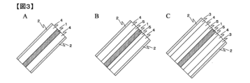
本発明の投影画像表示部材の別の態様の例として、透明支持体4と多層積層フィルム1を積層した積層体(図2 A~C)や、2つの透明支持体4の間に多層積層フィルム1が位置する積層体(図3 A~C)が挙げられる。透明支持体4の具体例としては、ガラスや透明樹脂基材などが挙げられ、支持性を持たせるためにその厚みは1mm以上が好ましい。透明支持体4の厚みの上限は特に限定されないが、厚みが過度に大きくなると投影画像表示部材の重量が不必要に増加するため、10mm以下が好ましい。
Examples of other embodiments of the projection image display member of the present invention include a laminate in which a
透明支持体4のガラスとしては、単層ガラスだけでなく自動車のフロントガラス、サイドガラス、リアガラスなどで用いられる合わせガラスや強化ガラス、ガラス建材の板ガラス、複層ガラス、真空ガラスなども用いることができる。また、透明支持体4の透明樹脂基材としては、ポリエチレンテレフタレート、ポリカーボネート、アクリル、ポリ塩化ビニル、ポリエチレン、ポリプロピレン、ポリメチルペンテン及びその共重合体、アクリロニトリル・ブタジエン・スチレン共重合体などが好ましい。これらの透明樹脂基材は、単一の成分でも、複数種を混合したものであってもよい。
As the glass for the
透明支持体4と多層積層フィルム1との積層方法としては、図2Aや図3Aのように直接貼り合わせる方法の他、図2B,C、図3B,Cに示すように、粘着剤や接着剤などを用いて接着層5を形成して両者を貼り合わせる方法等も用いることが可能である。粘着剤や接着剤として用いることができる成分としては、例えば、酢酸ビニル樹脂系、塩化ビニル・酢酸ビニル共重合体系、エチレン・酢酸ビニル共重合体系、ポリビニルアルコール、ポリビニルブチラール、ポリビニルアセタール、ポリビニルエーテル、ニトリルゴム系、スチレン・ブダジエンゴム系、天然ゴム系、クロロプレンゴム系、ポリアミド系、エポキシ樹脂系、ポリウレタン系、アクリル樹脂系、セルロース系、ポリ塩化ビニル、ポリアクリル酸エステル、ポリイソブチレン等が挙げられる。また、これらの粘着剤や接着剤は、単独で用いても複数種を混合して用いてもよく、また、必要に応じて粘着性調整剤、可塑剤、熱安定剤、酸化防止剤、紫外線吸収剤、帯電防止剤、滑剤、着色剤、架橋剤等を添加してもよい。
The
これら接着剤の加工前の形態としては、液状、ゲル状、塊状、粉末状、フィルム状などが挙げられる。接着層の固化方法としては、溶剤揮散、湿気硬化、加熱硬化、硬化剤混合、嫌気硬化、紫外線硬化、熱溶融冷却、感圧などが挙げられる。積層方法としてはラミネート成形、インジェクション成形、真空成型、圧空成形、真空・圧空併用成形などが挙げられ、加熱、加圧、上述した接着層の固化方法を用いることで投影画像表示部材を作製することができる。 Examples of the form of these adhesives before processing include liquid, gel, lump, powder, and film. Examples of methods for solidifying the adhesive layer include solvent volatilization, moisture curing, heat curing, curing agent mixing, anaerobic curing, ultraviolet curing, hot melt cooling, and pressure sensitive methods. Lamination methods include lamination molding, injection molding, vacuum molding, pressure forming, vacuum/pressure combined molding, etc., and the projection image display member can be produced by heating, pressurizing, and using the adhesive layer solidification method described above. Can be done.
本発明の投影画像表示部材は、投影画像表示部材面に垂直(投影画像表示部材面の接平面に対して0°の角度を意味する。)に入射する可視光の透過率が50%以上100%以下である必要がある。ここで「投影画像表示部材面に垂直に入射する可視光の透過率が50%以上100%以下である」とは、具体的には、投影画像表示部材面に垂直に入射した波長400~700nmの光の平均透過率が50%以上100%以下であることを示す。このように波長400~700nmの可視光領域の光の透過率が高いことにより、投影画像表示部材は、透明ガラスや透明樹脂フィルムのような透明性を具備する。そのため、このような態様の投影画像表示部材面に垂直な方向から、投影画像表示部材を通して背景を観察した際に、背景の良好な視認性を得ることができる。上記観点から当該透過率は、好ましくは70%以上であり、より好ましくは80%以上であり、さらに好ましくは90%以上である。当該透過率が90%以上であれば、利用者は投影画像表示部材の存在を感じることなく背景を視認することができる。なお、当該透過率の上限は実現可能性の観点から99%が好ましい。 The projection image display member of the present invention has a transmittance of 50% or more of visible light incident perpendicular to the surface of the projection image display member (meaning an angle of 0° with respect to the tangential plane of the surface of the projection image display member). % or less. Here, "the transmittance of visible light that is perpendicularly incident on the surface of the projection image display member is 50% or more and 100% or less" specifically means that the wavelength of visible light that is perpendicularly incident on the surface of the projection image display member is 400 to 700 nm. indicates that the average transmittance of light is 50% or more and 100% or less. Due to the high transmittance of light in the visible light region with a wavelength of 400 to 700 nm, the projection image display member has transparency similar to transparent glass or a transparent resin film. Therefore, when the background is observed through the projection image display member in such a manner from a direction perpendicular to the surface of the projection image display member, good visibility of the background can be obtained. From the above viewpoint, the transmittance is preferably 70% or more, more preferably 80% or more, and still more preferably 90% or more. If the transmittance is 90% or more, the user can visually recognize the background without feeling the presence of the projected image display member. Note that the upper limit of the transmittance is preferably 99% from the viewpoint of feasibility.
投影画像表示部材面に垂直に入射する光の透過率は、分光光度計で入射角度θ=0°における波長400~700nmの光の透過率を1nm刻みで測定し、その平均値を算出することにより測定することができる(詳細な測定条件は後述)。 To determine the transmittance of light incident perpendicularly to the surface of the projection image display member, measure the transmittance of light with a wavelength of 400 to 700 nm at an angle of incidence θ = 0° with a spectrophotometer in 1 nm increments, and calculate the average value. (Detailed measurement conditions will be described later).
本発明の投影画像表示部材は、投影画像表示部材の法線に対して20°、40°、60°の角度で入射したときのそれぞれのP波の反射率(%)をRp20、Rp40、Rp60とした場合にRp20≦Rp40<Rp60の関係を満足し、かつRp60が10%以上である必要がある。ここでいう「可視光が入射したときのP波の反射率」とは、波長400~700nmの範囲におけるP波の平均反射率とする。なお、このP波の反射率(%)は、分光光度計で入射角度θ=20°、40°、60°における波長400~700nmの範囲のP波の反射率を1nm刻みで測定し、その平均値を算出することで測定することができる(詳細な測定条件は後述)。透明ガラスや透明樹脂フィルムなどの一般的な透明基板の場合、フィルム面の法線に対して20°から徐々に入射角度を大きくしていくに従い、偏光の一つであるP波の反射率は低下し、ブリュースター角と呼ばれる角度で反射率は0%となる。したがって、一般的な透明基板では正面方向を透過し、斜め方向のP波を反射することは困難である。 The projection image display member of the present invention has a reflectance (%) of P waves of Rp20, Rp40, and Rp60 when the P waves are incident at angles of 20°, 40°, and 60° with respect to the normal line of the projection image display member. In this case, the relationship Rp20≦Rp40<Rp60 must be satisfied, and Rp60 must be 10% or more. The term "reflectance of P waves when visible light is incident" herein refers to the average reflectance of P waves in the wavelength range of 400 to 700 nm. The reflectance (%) of this P wave is determined by measuring the reflectance of P waves in the wavelength range of 400 to 700 nm in 1 nm increments at incident angles θ = 20°, 40°, and 60° using a spectrophotometer. It can be measured by calculating the average value (detailed measurement conditions will be described later). In the case of a general transparent substrate such as transparent glass or transparent resin film, as the incident angle is gradually increased from 20° to the normal to the film surface, the reflectance of P waves, which is one type of polarized light, will decrease. The reflectance decreases to 0% at an angle called Brewster's angle. Therefore, with a general transparent substrate, it is difficult to transmit the P wave in the front direction and reflect the P wave in the oblique direction.
投影画像表示部材面の法線に対して20°、40°、60°の角度で入射したときのそれぞれのP波の反射率をRp20、Rp40、Rp60としたときに、Rp20≦Rp40<Rp60の関係を満足し、かつRp60が10%以上である態様は、ブリュースター角に相当する角度を備えていない態様である。そのため、このような態様とすることにより、投影画像表示部材面に対して斜め方向から入射するP波の反射が可能となる。Rp60は好ましくは30%以上、より好ましくは50%以上であり、Rp60が高くなるに従い、投影画像表示部材面にP波の映像を投影した際の投影映像の表示性が高くなる。なお、Rp60の上限は特に制限されないが、実現可能性の観点から99%となる。 When the reflectances of P waves are Rp20, Rp40, and Rp60 when they are incident at angles of 20°, 40°, and 60° with respect to the normal to the surface of the projection image display member, Rp20≦Rp40<Rp60. An embodiment that satisfies the relationship and has Rp60 of 10% or more is an embodiment that does not have an angle equivalent to the Brewster angle. Therefore, by adopting such an aspect, it becomes possible to reflect the P waves that are incident on the surface of the projection image display member from an oblique direction. Rp60 is preferably 30% or more, more preferably 50% or more, and the higher the Rp60, the higher the displayability of the projected image when the P-wave image is projected onto the surface of the projection image display member. Note that the upper limit of Rp60 is not particularly limited, but is set to 99% from the viewpoint of feasibility.
本発明の投影画像表示部材が投影画像表示部材に垂直に入射する可視光の透過率を50%以上100%以下とし、投影画像表示部材の法線に対して20°、40°、60°の角度で入射したときのそれぞれのP波の反射率(%)をRp20、Rp40、Rp60とした場合にRp20≦Rp40<Rp60の関係を満足し、かつRp60が10%以上とする方法の一例として、例えば上記の特性を備える多層積層フィルムを含む態様とする方法が挙げられ、以下に詳細を説明する。
The projection image display member of the present invention has a transmittance of 50% or more and 100% or less of visible light incident perpendicularly to the projection image display member, and has an angle of 20°, 40°, or 60° with respect to the normal line of the projection image display member. As an example of a method for satisfying the relationship Rp20≦Rp40<Rp60 and making
本発明の投影画像表示部材は、異なる複数の熱可塑性樹脂層が交互に51層以上積層した多層積層フィルムを含むことが好ましい。本発明においては、組成の異なる熱可塑性樹脂層が多層積層フィルムに複数種存在し、かつこれらの熱可塑性樹脂層の屈折率がフィルムの面内で任意に選択される直交する2方向および該面に垂直な方向のいずれかにおいて、0.01以上異なる場合に「異なる複数の熱可塑性樹脂層が存在する。」とみなすことができる。また、交互に積層したとは、異なる熱可塑性樹脂からなる層が厚み方向に規則的な配列で積層されていることをいう。厚み方向とは、フィルム面に垂直な方向である。なお、積層構成の有無や各層の厚みは、透過型電子顕微鏡(TEM)で撮影した画像の解析により測定することができ、詳細は後述する。 The projection image display member of the present invention preferably includes a multilayer laminate film in which 51 or more different thermoplastic resin layers are alternately laminated. In the present invention, a plurality of types of thermoplastic resin layers having different compositions are present in a multilayer laminated film, and the refractive index of these thermoplastic resin layers is arbitrarily selected within the plane of the film in two orthogonal directions and in the plane. If the difference is 0.01 or more in any direction perpendicular to , it can be considered that "a plurality of different thermoplastic resin layers exist." In addition, "alternately laminated" means that layers made of different thermoplastic resins are laminated in a regular arrangement in the thickness direction. The thickness direction is a direction perpendicular to the film surface. Note that the presence or absence of a laminated structure and the thickness of each layer can be measured by analyzing images taken with a transmission electron microscope (TEM), and details will be described later.
このような態様の具体例としては、多層積層フィルムが第一の熱可塑性樹脂からなる層(層A)と第二の熱可塑性樹脂からなる層(層B)からなる場合であれば、A(BA)n、B(AB)n(nは繰り返し単位の数を表す自然数、以下同じ。)のように順に積層されたものが挙げられる。また、多層積層フィルムが第一の熱可塑性樹脂からなる層(層A)、第二の熱可塑性樹脂からなる層(層B)、及び第三の熱可塑性樹脂からなる層(層C)からなる場合であれば、その配列は特に限定されるものではないが、例えば、C(BA)nCやC(ABC)n、C(ACBC)nのように一定の規則性をもって厚み方向に積層されたものが挙げられる。このように屈折率等の光学的性質の異なる複数の熱可塑性樹脂層を規則的な配列で積層することにより、各層の屈折率の差と層厚みとの関係より所望の波長帯域の光を反射させる干渉反射を発現させることが可能となる。 As a specific example of such an aspect, if the multilayer laminated film is composed of a layer made of a first thermoplastic resin (layer A) and a layer made of a second thermoplastic resin (layer B), A( Examples include those laminated in order such as BA)n and B(AB)n (n is a natural number representing the number of repeating units, the same applies hereinafter). Further, the multilayer laminated film is composed of a layer made of a first thermoplastic resin (layer A), a layer made of a second thermoplastic resin (layer B), and a layer made of a third thermoplastic resin (layer C). If the arrangement is not particularly limited, for example, the arrangement is laminated in the thickness direction with a certain regularity, such as C(BA)nC, C(ABC)n, or C(ACBC)n. Things can be mentioned. By laminating multiple thermoplastic resin layers with different optical properties such as refractive index in a regular arrangement, light in the desired wavelength band can be reflected based on the relationship between the difference in refractive index of each layer and the layer thickness. It becomes possible to express interference reflection that causes
また、多層積層フィルムの層数が50層以下の場合には、所望する波長帯域において高い反射率を得られないことがある。前述の干渉反射は、層数が増えるほどより広い波長帯域の光に対して高い反射率を達成できるようになり、所望する波長帯域の光を反射する多層積層フィルムが得られるようになる。上記観点から、多層積層フィルムの層数は好ましくは401層以上であり、より好ましくは801層以上である。また、層数に上限はないものの、層数が増えるに従い製造装置の大型化に伴う製造コストの増加や、フィルム厚みが厚くなることでのハンドリング性の悪化が生じるために、現実的には10001層程度が実用範囲となり、好ましくは2001層程度である。 Furthermore, when the number of layers in the multilayer laminated film is 50 or less, it may not be possible to obtain a high reflectance in a desired wavelength band. In the above-mentioned interference reflection, as the number of layers increases, a higher reflectance can be achieved for light in a wider wavelength band, and a multilayer laminated film that reflects light in a desired wavelength band can be obtained. From the above viewpoint, the number of layers of the multilayer laminated film is preferably 401 or more, more preferably 801 or more. In addition, although there is no upper limit to the number of layers, as the number of layers increases, manufacturing costs increase due to larger manufacturing equipment, and handling performance deteriorates due to thicker films, so in reality, 10001 The number of layers falls within a practical range, and is preferably about 2001 layers.
多層積層フィルムに垂直に入射する可視光の透過率は、2つの熱可塑性樹脂層の間のフィルム面に平行な方向の屈折率差を小さくすることで低くすることができる。例えば、多層積層フィルムの層数が前述の範囲であれば、フィルム面に平行な方向の屈折率差が0.06以下であれば当該透過率を50%以上に、0.04以下であれば当該透過率を70%以上に、屈折率差が0.02以下であれば当該透過率を80%以上にすることが容易となる。なお、「フィルム面に平行な方向の屈折率差」とは、隣接する熱可塑性樹脂層間の面内屈折率の差(2種類の層を層A、層Bとした場合は、層Aと層Bの面内屈折率の差をいい、3種類の層を層A、層B、層Cとした場合は、層Aと層Bの面内屈折率の差、層Bと層Cの面内屈折率の差、層Cと層Aの面内屈折率の差)の絶対値をいう。また、フィルム面に平行な方向の屈折率差を小さくすることで、後述のRs60-Rs20を小さくできるため好ましい。 The transmittance of visible light incident perpendicularly to the multilayer laminated film can be lowered by reducing the difference in refractive index between the two thermoplastic resin layers in the direction parallel to the film plane. For example, if the number of layers of the multilayer laminated film is within the above range, if the refractive index difference in the direction parallel to the film surface is 0.06 or less, the transmittance will be 50% or more, and if it is 0.04 or less, the transmittance will be 50% or more. If the transmittance is 70% or more and the refractive index difference is 0.02 or less, it is easy to increase the transmittance to 80% or more. Note that the "difference in refractive index in the direction parallel to the film surface" refers to the difference in in-plane refractive index between adjacent thermoplastic resin layers (if the two types of layers are layer A and layer B, the difference in refractive index in the direction parallel to the film surface) This refers to the difference in the in-plane refractive index of B, and when three types of layers are layer A, layer B, and layer C, the in-plane refractive index difference between layer A and layer B, and the in-plane refractive index difference between layer B and layer C. It refers to the absolute value of the difference in refractive index (the difference in in-plane refractive index between layer C and layer A). Further, by reducing the refractive index difference in the direction parallel to the film surface, Rs60-Rs20, which will be described later, can be reduced, which is preferable.
Rp20≦Rp40<Rp60の関係を満足し、かつRp60が10%以上である多層積層フィルムを得るためには、2つの熱可塑性樹脂層の間のフィルム面に垂直な方向の屈折率差と層数を調整する方法を用いることができる。このときフィルム面に垂直な方向の屈折率差を大きくするほど、そして層数を増やすほど、Rp60を大きくすることができる。例えば、層数が801層に達する場合、フィルム面に垂直な方向の屈折率差が0.08以上であれば当該反射率を30%以上に、屈折率差が0.12以上であれば当該反射率を50%以上にすることが容易となり、その結果、投影画像表示部材の法線に対して20°、40°、60°の角度で入射したときのそれぞれのP波の反射率(%)をRp20、Rp40、Rp60とした場合にRp20≦Rp40<Rp60の関係を満足し、かつRp60が10%以上にすることが出来る。また、屈折率差が上記水準に達していなくとも、層数をさらに増やすことで当該反射率を高めて上記水準に到達させることもできる。なお、以下フィルム面に垂直な方向の屈折率を、面直屈折率ということがある。 In order to obtain a multilayer laminated film that satisfies the relationship Rp20≦Rp40<Rp60 and has Rp60 of 10% or more, the refractive index difference in the direction perpendicular to the film surface between the two thermoplastic resin layers and the number of layers must be adjusted. A method can be used to adjust the At this time, Rp60 can be increased as the refractive index difference in the direction perpendicular to the film surface increases and as the number of layers increases. For example, when the number of layers reaches 801, if the refractive index difference in the direction perpendicular to the film surface is 0.08 or more, the reflectance is set to 30% or more, and if the refractive index difference is 0.12 or more, the corresponding reflectance is set to 30% or more. It is easy to increase the reflectance to 50% or more, and as a result, the reflectance (% ) are set to Rp20, Rp40, and Rp60, the relationship Rp20≦Rp40<Rp60 is satisfied, and Rp60 can be set to 10% or more. Further, even if the refractive index difference does not reach the above level, the reflectance can be increased to reach the above level by further increasing the number of layers. Hereinafter, the refractive index in the direction perpendicular to the film surface may be referred to as perpendicular refractive index.
多層積層フィルムの反射波長を波長400~700nmの範囲に調整する方法は、2つの熱可塑性樹脂層の面直屈折率差、積層数、層厚み分布、製膜条件(例えば延伸倍率、延伸速度、延伸温度、熱処理温度、熱処理時間)の調整等が挙げられる。 The method of adjusting the reflection wavelength of a multilayer laminated film to a wavelength range of 400 to 700 nm is based on the perpendicular refractive index difference between two thermoplastic resin layers, the number of laminated layers, layer thickness distribution, film forming conditions (e.g., stretching ratio, stretching speed, Adjustment of stretching temperature, heat treatment temperature, heat treatment time, etc.
本発明の投影画像表示部材においては、多層積層フィルムが、2種の熱可塑性樹脂層が交互に積層された構成を有し、第一の熱可塑性樹脂からなる層を層Aとし、第二の熱可塑性樹脂からなる層を層Bとしたときに、層Aが結晶性の熱可塑性樹脂を含み、層Bが非晶性の熱可塑性樹脂を主成分とすることが好ましい。より好ましくは、層Aが結晶性の熱可塑性樹脂を主成分とし、層Bが非晶性の熱可塑性樹脂を主成分とすることである。さらに好ましくは、層Aが結晶性の熱可塑性樹脂からなり、層Bが非晶性の熱可塑性樹脂を主成分とすることである。ここで主成分とは、層を構成する全成分を100質量%としたときに、70質量%以上100質量%以下含まれる成分をいう。また、反射率が高くなり積層数が少なく済むことから、層Aと層Bの面直屈折率差は高い方が好ましい。層厚み分布は隣接する層Aと層Bの光学厚みが下記(A)式を満たすことが好ましい。なお、層Aにおける結晶性の熱可塑性樹脂、層Bにおける非晶性の熱可塑性樹脂は、いずれもポリエステルであることが好ましい。 In the projection image display member of the present invention, the multilayer laminated film has a structure in which two types of thermoplastic resin layers are alternately laminated, and the first layer made of thermoplastic resin is layer A, and the second layer is made of thermoplastic resin. When layer B is a layer made of a thermoplastic resin, it is preferable that layer A contains a crystalline thermoplastic resin and layer B contains an amorphous thermoplastic resin as a main component. More preferably, layer A has a crystalline thermoplastic resin as a main component, and layer B has an amorphous thermoplastic resin as a main component. More preferably, layer A is made of a crystalline thermoplastic resin, and layer B is made of an amorphous thermoplastic resin as a main component. Here, the main component refers to a component that is contained in an amount of 70% by mass or more and 100% by mass or less when all components constituting the layer are 100% by mass. Further, since the reflectance is high and the number of laminated layers can be reduced, it is preferable that the difference in perpendicular refractive index between layer A and layer B is high. Regarding the layer thickness distribution, it is preferable that the optical thicknesses of adjacent layers A and B satisfy the following formula (A). Note that the crystalline thermoplastic resin in layer A and the amorphous thermoplastic resin in layer B are both preferably polyester.
![]()
![]()
ここでλは反射波長、nAは層Aの面直屈折率、dAは層Aの厚み、nBは層Bの面直屈折率、dBは層Bの厚みである。 Here, λ is the reflection wavelength, n A is the normal refractive index of layer A, d A is the thickness of layer A, n B is the normal refractive index of layer B, and d B is the thickness of layer B.
層厚みの分布は、多層積層フィルム面の一方から反対側の面へ向かって一定の層厚み分布とすること、多層積層フィルム面の一方から反対側へ向かって増加または減少する層厚み分布とすること、多層積層フィルム面の一方からフィルム中心へ向かって層厚みが増加した後減少する層厚み分布とすること、多層積層フィルム面の一方からフィルム中心へ向かって層厚みが減少した後増加する層厚み分布とすること、又はこれらの分布を組み合わせたものとすることが好ましい。層厚み分布の変化の仕方としては、線形、等比、階差数列といった連続的に変化するものや、10層から50層程度の層がほぼ同じ層厚みを持ち、その層厚みがステップ状に変化するものが好ましい。 The layer thickness distribution shall be a constant layer thickness distribution from one side of the multilayer laminated film surface to the opposite side, or a layer thickness distribution that increases or decreases from one side of the multilayer laminated film surface to the opposite side. The layer thickness distribution is such that the layer thickness increases from one side of the multilayer laminated film toward the center of the film, and then decreases, and the layer thickness decreases and then increases from one side of the multilayer laminated film toward the center of the film. It is preferable to have a thickness distribution or a combination of these distributions. The layer thickness distribution may change continuously, such as linearly, geometrically, or in a stepwise progression, or in which 10 to 50 layers have approximately the same layer thickness, and the layer thickness changes in a step-like manner. Preferably something that changes.
多層積層フィルムの両表層には、保護層として厚みが多層積層フィルム自体の厚みの1%以上である層を好ましく設けることができ、各保護層の厚みは好ましくは多層積層フィルムの厚み全体に対して4%以上である。保護層の厚みが厚くなることで、製膜時のフローマークの抑制や設計に対する実際の各層の層厚みの精度向上、他のフィルムや成形体とのラミネート工程及びラミネート工程後における多層積層フィルム中の薄膜層の変形抑制、耐押圧性などに繋がる。なお、当該保護層の厚みの上限は、多層積層フィルムの厚みの増加を抑えつつ干渉反射の発現に必要な積層構成部分を確保する観点から、20%となる。本発明の投影画像表示部材を構成する多層積層フィルムの厚みは、特に限られるものではないが、例えば20μm~300μmであることが好ましい。20μm以上であると、多層積層フィルムの腰が強くなりハンドリング性が確保できる。また、300μm以下であると、多層積層フィルムの腰が過度に強くならず、成形性が向上する。 A layer having a thickness of 1% or more of the thickness of the multilayer laminate film itself can be preferably provided as a protective layer on both surface layers of the multilayer laminate film, and the thickness of each protective layer is preferably 1% or more of the thickness of the multilayer laminate film itself. 4% or more. The thicker protective layer suppresses flow marks during film production, improves the accuracy of the actual layer thickness of each layer based on the design, and improves the lamination process with other films and molded bodies, and in multilayer laminated films after the lamination process. This leads to suppression of deformation of the thin film layer and resistance to pressure. Note that the upper limit of the thickness of the protective layer is 20% from the viewpoint of securing the laminated constituent parts necessary for the expression of interference reflection while suppressing an increase in the thickness of the multilayer laminated film. The thickness of the multilayer laminated film constituting the projection image display member of the present invention is not particularly limited, but is preferably 20 μm to 300 μm, for example. When the thickness is 20 μm or more, the multilayer laminated film becomes stiff and handleability can be ensured. Moreover, when it is 300 μm or less, the stiffness of the multilayer laminated film is not excessively strong, and the moldability is improved.
また、多層積層フィルムの少なくとも一方の表面にプライマー層、ハードコート層、耐磨耗性層、傷防止層、反射防止層、色補正層、紫外線吸収層、光安定化層、熱線吸収層、印刷層、ガスバリア層、粘着層などの機能性層を形成してもよい。これらの層は単層構成でも多層構成でもよく、また、1つの層に複数の機能を持たせてもよい。また、多層積層フィルム中に、紫外線吸収剤、光安定化剤(HALS)、熱線吸収剤、結晶核剤、可塑剤などの添加剤を含んでいてもよい。なお、これらの成分は、本発明の効果を損なわない範囲で、組み合わせて用いることも可能である。 Furthermore, on at least one surface of the multilayer laminated film, a primer layer, a hard coat layer, an abrasion resistant layer, an anti-scratch layer, an antireflection layer, a color correction layer, an ultraviolet absorbing layer, a light stabilizing layer, a heat ray absorbing layer, and printing are provided. A functional layer such as a layer, a gas barrier layer, an adhesive layer, etc. may be formed. These layers may have a single layer structure or a multilayer structure, and one layer may have a plurality of functions. Further, the multilayer laminated film may contain additives such as ultraviolet absorbers, light stabilizers (HALS), heat ray absorbers, crystal nucleating agents, and plasticizers. In addition, these components can also be used in combination within a range that does not impair the effects of the present invention.
本発明の投影画像表示部材を構成する多層積層フィルムに用いる熱可塑性樹脂は、ポリエチレン、ポリプロピレン、ポリ(4-メチルペンテン-1)、ポリアセタールなどの鎖状ポリオレフィン、ノルボルネン類の開環メタセシス重合体,付加重合体,他のオレフィン類との付加共重合体である脂環族ポリオレフィン、ポリ乳酸、ポリブチルサクシネートなどの生分解性ポリマー、ナイロン6、ナイロン11、ナイロン12、ナイロン66などのポリアミド、アラミド、ポリメチルメタクリレート、ポリ塩化ビニル、ポリ塩化ビニリデン、ポリビニルアルコール、ポリビニルブチラール、エチレン酢酸ビニルコポリマー、ポリアセタール、ポリグルコール酸、ポリスチレン、スチレン共重合ポリメタクリル酸メチル、ポリカーボネート、ポリプロピレンテレフタレート、ポリエチレンテレフタレート、ポリブチレンテレフタレート、ポリエチレン-2,6-ナフタレートなどのポリエステル、ポリエーテルサルフォン、ポリエーテルエーテルケトン、変性ポリフェニレンエーテル、ポリフェニレンサルファイド、ポリエーテルイミド、ポリイミド、ポリアリレート、4フッ化エチレン樹脂、3フッ化エチレン樹脂、3フッ化塩化エチレン樹脂、4フッ化エチレン-6フッ化プロピレン共重合体、ポリフッ化ビニリデンなどを用いることができる。この中で、強度・耐熱性・透明性および汎用性の観点から、特にポリエステルを用いることがより好ましい。これらは、共重合体であっても、2種以上の樹脂の混合物であってもよい。
The thermoplastic resin used in the multilayer laminated film constituting the projection image display member of the present invention includes chain polyolefins such as polyethylene, polypropylene, poly(4-methylpentene-1), and polyacetal, ring-opening metathesis polymers of norbornenes, addition polymers, alicyclic polyolefins that are addition copolymers with other olefins, biodegradable polymers such as polylactic acid and polybutyl succinate, polyamides such as
ポリエステルとは、ジカルボン酸単位とジオール単位がエステル結合により繋がった分子構造を有する樹脂をいう。ポリエステルとしては、芳香族ジカルボン酸または脂肪族ジカルボン酸とジオールを主たる構成成分とする単量体からの重合により得られるポリエステルが好ましい。ここで、芳香族ジカルボン酸として、例えば、テレフタル酸、イソフタル酸、フタル酸、1,4-ナフタレンジカルボン酸、1,5-ナフタレンジカルボン酸、2,6-ナフタレンジカルボン酸、4,4′-ジフェニルジカルボン酸、4,4′-ジフェニルエーテルジカルボン酸、4,4′-ジフェニルスルホンジカルボン酸などを挙げることができる。脂肪族ジカルボン酸としては、例えば、アジピン酸、スベリン酸、セバシン酸、ダイマー酸、ドデカンジオン酸、シクロヘキサンジカルボン酸とそれらのエステル誘導体などが挙げられる。中でも高い屈折率を発現するテレフタル酸と2,6ナフタレンジカルボン酸が好ましい。これらの酸成分は1種のみ用いてもよく、2種以上併用してもよく、さらには、ヒドロキシ安息香酸等のオキシ酸などを一部共重合してもよい。 Polyester refers to a resin having a molecular structure in which dicarboxylic acid units and diol units are connected through ester bonds. As the polyester, a polyester obtained by polymerization from a monomer whose main components are an aromatic dicarboxylic acid or an aliphatic dicarboxylic acid and a diol is preferable. Here, examples of aromatic dicarboxylic acids include terephthalic acid, isophthalic acid, phthalic acid, 1,4-naphthalenedicarboxylic acid, 1,5-naphthalenedicarboxylic acid, 2,6-naphthalenedicarboxylic acid, 4,4'-diphenyl Examples include dicarboxylic acid, 4,4'-diphenyl ether dicarboxylic acid, and 4,4'-diphenylsulfone dicarboxylic acid. Examples of aliphatic dicarboxylic acids include adipic acid, suberic acid, sebacic acid, dimer acid, dodecanedioic acid, cyclohexanedicarboxylic acid, and ester derivatives thereof. Among them, terephthalic acid and 2,6-naphthalene dicarboxylic acid, which exhibit a high refractive index, are preferred. These acid components may be used alone or in combination of two or more, and furthermore, oxyacids such as hydroxybenzoic acid may be partially copolymerized.
また、ジオール成分としては、例えば、エチレングリコール、1,2-プロパンジオール、1,3-プロパンジオール、ネオペンチルグリコール、1,3-ブタンジオール、1,4-ブタンジオール、1,5-ペンタンジオール、1,6-ヘキサンジオール、1,2-シクロヘキサンジメタノール、1,3-シクロヘキサンジメタノール、1,4-シクロヘキサンジメタノール、ジエチレングリコール、トリエチレングリコール、ポリアルキレングリコール、2,2-ビス(4-ヒドロキシエトキシフェニル)プロパン、イソソルベート、スピログリコールなどを挙げることができる。中でもエチレングリコールが好ましく用いられる。これらのジオール成分は1種のみ用いてもよく、2種以上併用してもよい。 In addition, examples of diol components include ethylene glycol, 1,2-propanediol, 1,3-propanediol, neopentyl glycol, 1,3-butanediol, 1,4-butanediol, and 1,5-pentanediol. , 1,6-hexanediol, 1,2-cyclohexanedimethanol, 1,3-cyclohexanedimethanol, 1,4-cyclohexanedimethanol, diethylene glycol, triethylene glycol, polyalkylene glycol, 2,2-bis(4- Examples include hydroxyethoxyphenyl)propane, isosorbate, spiroglycol, and the like. Among them, ethylene glycol is preferably used. These diol components may be used alone or in combination of two or more.
本発明の多層積層フィルムの各層の主成分となる熱可塑性樹脂としては、例えば、上記ポリエステルのうち、ポリエチレンテレフタレートおよびその重合体、ポリエチレンナフタレートおよびその共重合体、ポリブチレンテレフタレートおよびその共重合体、ポリブチレンナフタレートおよびその共重合体、さらにはポリヘキサメチレンテレフタレートおよびその共重合体、ポリヘキサメチレンナフタレートおよびその共重合体から選択することが好ましい。 Examples of the thermoplastic resin that is the main component of each layer of the multilayer laminated film of the present invention include polyethylene terephthalate and its polymer, polyethylene naphthalate and its copolymer, polybutylene terephthalate and its copolymer among the above polyesters. , polybutylene naphthalate and its copolymers, furthermore polyhexamethylene terephthalate and its copolymers, polyhexamethylene naphthalate and its copolymers.
また、熱可塑性樹脂中には、各種添加剤、例えば、酸化防止剤、耐熱安定剤、耐候安定剤、紫外線吸収剤、有機系易滑剤、顔料、染料、有機または無機の微粒子、充填剤、帯電防止剤、および核剤などを、その特性を悪化させない程度に単独で又は複数成分を組み合わせて添加させることができる。 Thermoplastic resins also contain various additives, such as antioxidants, heat stabilizers, weather stabilizers, ultraviolet absorbers, organic lubricants, pigments, dyes, organic or inorganic fine particles, fillers, and electrostatic charges. Inhibitors, nucleating agents, and the like can be added singly or in combination to the extent that their properties are not deteriorated.
本発明の投影画像表示部材は、ヘッドアップディスプレイなどの投影画像表示装置に用いた場合における映り込み軽減の観点から、投影画像表示部材面の法線に対して20°、60°の角度で可視光が入射したときのそれぞれのS波の反射率(%)をRs20、Rs60とした場合に、Rs60-Rs20が25%以下であることが必要である。上記観点から、Rs60-Rs20は20%以下が好ましく、より好ましくは10%以下である。Rs60-Rs20が小さくなるほど、S波の斜め反射が抑制されるため、本発明の投影画像表示部材をヘッドアップディスプレイなどの投影画像表示装置に用いた場合において、映像以外の周囲の景色の映り込みを抑制することができる。なお、Rs60-Rs20の下限は特に制限されないが、実現可能性の観点から1%となる。 The projection image display member of the present invention is visible at angles of 20° and 60° with respect to the normal to the surface of the projection image display member, from the viewpoint of reducing glare when used in a projection image display device such as a head-up display. When the reflectance (%) of each S wave when light is incident is assumed to be Rs20 and Rs60, it is necessary that Rs60-Rs20 be 25% or less. From the above viewpoint, Rs60-Rs20 is preferably 20% or less, more preferably 10% or less. As Rs60-Rs20 becomes smaller, oblique reflection of S waves is suppressed, so when the projection image display member of the present invention is used in a projection image display device such as a head-up display, reflection of surrounding scenery other than the image is reduced. can be suppressed. Note that the lower limit of Rs60-Rs20 is not particularly limited, but is set to 1% from the viewpoint of feasibility.
P波及びS波は以下のように定義することができる。電磁波(光)が物体の表側の面に対し斜め方向から入射した際において、P波とは電界成分が入射面に平行な電磁波(入射面に平行に振動する直線偏光)、S波とは電界成分が入射面に垂直な電磁波(入射面に垂直に振動する直線偏光)を表す。このP波とS波の反射特性について、図面を参照しながら説明する。図4に従来の透明樹脂フィルム(一般的な透明基板)について、図5に従来の光を反射する多層積層フィルムについて、図6に特許文献1や2に記載された多層積層フィルムについて、図7に本発明の投影画像表示部材が含む多層積層フィルムについて、空気中から各フィルムに波長550nmのP波とS波の光が入射した際の反射率の角度依存性を表したグラフ(一例)を示す。ここでは一例として波長550nmで示したが、他の可視光の波長においても、各フィルムはそれぞれ図4~7で示したのと概ね同様の関係性を有する。なお、図4~7において符号6、7はそれぞれP波の反射率、S波の反射率を表す。
P waves and S waves can be defined as follows. When electromagnetic waves (light) enter the front surface of an object from an oblique direction, P waves are electromagnetic waves whose electric field components are parallel to the incident surface (linearly polarized light vibrating parallel to the incident surface), and S waves are electromagnetic waves whose electric field component is parallel to the incident surface. Represents electromagnetic waves whose components are perpendicular to the plane of incidence (linearly polarized light that vibrates perpendicular to the plane of incidence). The reflection characteristics of P waves and S waves will be explained with reference to the drawings. FIG. 4 shows a conventional transparent resin film (general transparent substrate), FIG. 5 shows a conventional multilayer laminate film that reflects light, and FIG. 6 shows a multilayer laminate film described in
図4に示すように一般的な透明基板はフレネルの式に従い、P波の反射率は入射角度が増大するとともに低下して0%となった後、再度増大する傾向を示す。一方、S波の反射率は入射角度が増大するとともに増大する。図5に示すように従来の光を反射する多層積層フィルムは、P波もS波も入射角度0度で一定の反射率を持つため透過率が低く、さらに入射角度増大とともにP波、S波両方の反射率が増大する。図6に示すように特許文献1や2に記載された多層積層フィルムは、入射角度0度ではP波とS波両方の反射率が低く(透過率が高く)、入射角度増大とともにP波とS波両方の反射率が増大する特徴を持つ。一方、図7に示すように本発明の投影画像表示部材が含む多層積層フィルムは、入射角度0°では、P波、S波両方の反射率が低く(透過率が高く)、P波の反射率が入射角度増大とともに増大し、S波の反射率は入射角度60°程度までは増大しても殆ど変わらない又は減少し、入射角度70°程度から増大する傾向を示す。このように、本発明の投影画像表示部材が含む多層積層フィルムは、透明基板のS波とP波の反射特性が逆転した特徴を持つ。ここで、本発明の多層積層フィルムは、2つの熱可塑性樹脂層の間のフィルム面に平行な方向の屈折率差を小さくし、2つの熱可塑性樹脂層の間のフィルム面に垂直な方向の屈折率差を大きくしているため、斜め方向の反射において、P波の反射は多層積層フィルム内部の干渉反射によって発現し、S波の反射は多層積層フィルムの表面反射によって発現している。よって、透明基板のS波とP波の反射特性を逆転させる方法として、投影画像表示部材や多層積層フィルムの表面反射を抑制することが挙げられる。
As shown in FIG. 4, a general transparent substrate follows Fresnel's equation, and the reflectance of P waves tends to decrease to 0% as the incident angle increases, and then increase again. On the other hand, the reflectance of S waves increases as the angle of incidence increases. As shown in Figure 5, conventional multilayer laminated films that reflect light have low transmittance because both P waves and S waves have a constant reflectance at an incident angle of 0 degrees, and as the incident angle increases, P waves and S waves Both reflectances increase. As shown in Figure 6, the multilayer laminated films described in
本発明の投影画像表示部材が図7のような反射特性を持つための方法としては、投影画像表示部材表面の反射、特に投影画像表示部材表面における斜め方向のS波の反射を抑制する方法があげられる。その具体例としては、例えば、投影画像表示部材の少なくとも一方の表面に、屈折率1.5以下の低屈折率層を少なくとも一つ有することがあげられる。本方法において低屈折率層は、反射防止層として機能する。また、別の例として、投影画像表示部材の少なくとも一方の表面に凸部間の平均間隔と凸部の平均高さが、共に10nm~400nmの範囲である凹凸構造を含む例が挙げられる。ここでいう屈折率は、面内方向と面直方向の平均屈折率である(等方性の樹脂を用いている場合はいずれか一方の方向の屈折率で代用できる。)。これらの低屈折率層や凹凸構造は投影画像表示部材両面に形成することで、投影画像表示部材表面における斜め方向のS波の反射を更に抑制することができる。このように、投影画像表示部材表面に上述した反射防止機構を有することによって、Rs60-Rs20をより小さくすることができ、本発明の投影画像表示部材をヘッドアップディスプレイなどの投影画像表示装置に用いた場合において、映像以外の周囲の景色の映り込みを抑制することができる。 As a method for the projection image display member of the present invention to have the reflection characteristics as shown in FIG. 7, there is a method of suppressing reflection on the surface of the projection image display member, particularly reflection of S waves in an oblique direction on the surface of the projection image display member. can give. A specific example thereof is, for example, having at least one low refractive index layer having a refractive index of 1.5 or less on at least one surface of the projection image display member. In this method, the low refractive index layer functions as an antireflection layer. Further, as another example, there is an example in which at least one surface of the projection image display member includes an uneven structure in which the average interval between the convex parts and the average height of the convex parts are both in the range of 10 nm to 400 nm. The refractive index referred to here is the average refractive index in the in-plane direction and the perpendicular direction (if an isotropic resin is used, the refractive index in either direction can be substituted). By forming these low refractive index layers and uneven structures on both surfaces of the projection image display member, it is possible to further suppress reflection of S waves in oblique directions on the surface of the projection image display member. As described above, by providing the above-mentioned anti-reflection mechanism on the surface of the projection image display member, Rs60-Rs20 can be made smaller, and the projection image display member of the present invention can be used in a projection image display device such as a head-up display. In this case, it is possible to suppress the reflection of surrounding scenery other than the image.
屈折率1.5以下の低屈折率層は、例えば、低屈折率材料の塗布や金属酸化物の蒸着、スパッタリングなどで形成することができる。屈折率の下限としては実現可能性の観点から1.2となる。低屈折率材料の塗布における材料としては、バインダー樹脂中に中空アクリル、中空酸化ケイ素、コロイダル酸化ケイ素、中空シリカ、LaF3、MgF2などの微粒子を混合したものや、含フッ素化合物などがあげられる。含フッ素化合物としては含フッ素メタアクリレートや含フッ素多官能メタアクリレートなどが挙げられ、含フッ素化合物をバインダー樹脂として用いることも挙げられる。微粒子の1次粒子の平均粒子径はヘイズ抑制の観点から20nm~200nmが好ましく、より好ましくは20nm~100nmである。また、微粒子は表面処理を行うことで粒子同士の凝集を抑制してヘイズを抑制することが好ましい。表面処理の方法としてはバインダー樹脂との親和性が高いシランカップリング剤を用いることが好ましい。蒸着、スパッタリングに用いる金属酸化物としては、LiF、MgF2、SiO2、Na5Al3F14、Na3AlF6などが挙げられる。なお、微粒子の1次粒子の平均粒子径は動的光散乱法により測定することができる。 The low refractive index layer having a refractive index of 1.5 or less can be formed, for example, by coating a low refractive index material, vapor deposition of a metal oxide, sputtering, or the like. The lower limit of the refractive index is 1.2 from the viewpoint of feasibility. Examples of materials for applying the low refractive index material include binder resin mixed with fine particles such as hollow acrylic, hollow silicon oxide, colloidal silicon oxide, hollow silica, LaF 3 and MgF 2 , and fluorine-containing compounds. . Examples of the fluorine-containing compound include fluorine-containing methacrylate and fluorine-containing polyfunctional methacrylate, and the use of the fluorine-containing compound as a binder resin is also mentioned. The average particle diameter of the primary particles of the fine particles is preferably 20 nm to 200 nm, more preferably 20 nm to 100 nm, from the viewpoint of haze suppression. Further, it is preferable that the fine particles be subjected to surface treatment to suppress aggregation of the particles and suppress haze. As a surface treatment method, it is preferable to use a silane coupling agent that has high affinity with the binder resin. Examples of metal oxides used for vapor deposition and sputtering include LiF, MgF 2 , SiO 2 , Na 5 Al 3 F 14 , and Na 3 AlF 6 . Note that the average particle diameter of the primary particles of the fine particles can be measured by a dynamic light scattering method.
本発明の投影画像表示部材において、低屈折率層の屈折率nと層厚みdの積n×dは150nm以上250nm以下が好ましく、より好ましくは170nm以上220nm以下である。低屈折率材料を用いた一般的な反射防止層は入射角度0°の反射を軽減するように設計しており、そのときのn×dの値は120nm前後である。そのため入射角度が大きくなると斜め方向の反射防止効果が小さくなる。一方で、本発明の多層積層フィルムではn×dの値を150nm以上250nm以下とすることで入射角度が増大しても斜め方向の反射防止効果を持たせることができる。 In the projection image display member of the present invention, the product n×d of the refractive index n and layer thickness d of the low refractive index layer is preferably 150 nm or more and 250 nm or less, more preferably 170 nm or more and 220 nm or less. A general antireflection layer using a low refractive index material is designed to reduce reflection at an incident angle of 0°, and the value of n×d at that time is approximately 120 nm. Therefore, as the incident angle increases, the antireflection effect in the oblique direction decreases. On the other hand, in the multilayer laminated film of the present invention, by setting the value of n×d to 150 nm or more and 250 nm or less, it is possible to provide an antireflection effect in an oblique direction even when the incident angle increases.
本発明の投影画像表示部材は、表面と屈折率1.5以下の低屈折率層の間に屈折率1.7以上の高屈折率層を設けることも好ましい。この高屈折率層としては高屈折率材料の塗布や金属酸化物の蒸着、スパッタリングなどで形成することができる。高屈折率材料としてはNb2O5、Sb2O3、ZrO2、TiO2、Y2O3、SiO、ZnO、In2O3、Ta2O5、CeO2、SnO2、ITO、ATOなどが挙げられる。高屈折率層の形成方法としては、例えば、これらの高屈折率材料の微粒子をバインダー樹脂中に混合した塗液を塗布して乾燥する方法や、蒸着やスパッタリングによって上記高屈折率材料からなる高屈折率層を形成する方法が挙げられる。上記高屈折率材料を微粒子として用いた場合の1次粒子の平均粒子径はヘイズ抑制の観点から20nm~200nmが好ましく、より好ましくは20nm~100nmである。また、微粒子は表面処理を行うことで粒子同士の凝集を抑制してヘイズを抑制することが好ましい。表面処理の方法としてはバインダー樹脂との親和性が高いシランカップリング剤を用いることが好ましい。なお、微粒子の1次粒子の平均粒子径は動的光散乱法により測定することができる。 In the projection image display member of the present invention, it is also preferable that a high refractive index layer having a refractive index of 1.7 or more is provided between the surface and the low refractive index layer having a refractive index of 1.5 or less. This high refractive index layer can be formed by coating a high refractive index material, vapor depositing a metal oxide, sputtering, or the like. High refractive index materials include Nb2O5 , Sb2O3 , ZrO2 , TiO2 , Y2O3 , SiO, ZnO , In2O3 , Ta2O5 , CeO2 , SnO2 , ITO, and ATO . Examples include. The high refractive index layer can be formed by, for example, applying a coating liquid in which fine particles of these high refractive index materials are mixed in a binder resin and drying, or forming a high refractive index layer made of the high refractive index materials by vapor deposition or sputtering. Examples include a method of forming a refractive index layer. When the above-mentioned high refractive index material is used as fine particles, the average particle diameter of the primary particles is preferably 20 nm to 200 nm, more preferably 20 nm to 100 nm, from the viewpoint of haze suppression. Further, it is preferable that the fine particles be subjected to surface treatment to suppress aggregation of the particles and suppress haze. As a surface treatment method, it is preferable to use a silane coupling agent that has high affinity with the binder resin. Note that the average particle diameter of the primary particles of the fine particles can be measured by a dynamic light scattering method.
高屈折率層の屈折率nHと層厚みdHの積nH×dHは150nm以上250nm以下が好ましく、より好ましくは170nm以上220nm以下である。高屈折率材料を用いた一般的な反射防止層は入射角度0°の反射を防止するように設計しており、nH×dHの値は120nm前後である。そのため入射角度が大きくなると斜め方向の反射防止効果が小さくなる。また、nH×dHの値は300nm以上500nm以下も好ましく、より好ましくは340nm以上440nm以下である。 The product nH×dH of the refractive index nH and layer thickness dH of the high refractive index layer is preferably 150 nm or more and 250 nm or less, more preferably 170 nm or more and 220 nm or less. A general antireflection layer using a high refractive index material is designed to prevent reflection at an incident angle of 0°, and the value of nH×dH is around 120 nm. Therefore, as the incident angle increases, the antireflection effect in the oblique direction decreases. Moreover, the value of nH×dH is also preferably 300 nm or more and 500 nm or less, more preferably 340 nm or more and 440 nm or less.
凸部間の平均間隔と凸部の平均高さが、共に10nm~400nmの範囲である凹凸構造はモスアイ構造とも呼ばれる。凸部間の平均間隔と凸部の平均高さが、波長400nm~700nmの範囲である可視光の波長以下である凹凸構造を持つことで、投影画像表示部材表面の反射を軽減することができる。図8に本発明の投影画像表示部材が含む凹凸構造の一例を示す。図8の中で符号8は凹凸構造を含む投影画像表示部材、符号9は凹凸構造付近の拡大断面図、符号10は凹凸構造側から見た拡大上面図、符号11は凹凸構造のない投影画像表示部材である。凹凸構造12は凸部14と基材15からなる構成が凹凸構造のない投影画像表示部材(符号13に表面付近の断面図を示す。)の表面に形成された態様が挙げられるが、基材15が無く凸部14が投影画像表示部材13に直接形成される構成も取り得る。凸部14の形状は凸部の根元19から凸部の先端20に向かって凸部の径が小さくなっていく形状が好ましい。凸部の根元19から凸部の先端20に向かって凸部の径が小さくなることで、凸部の先端20から凸部の根元19に向かって屈折率が連続的に変化していくため反射が軽減され、投影画像表示部材の表面反射を抑制することができる。
A concavo-convex structure in which the average interval between convex portions and the average height of convex portions are both in the range of 10 nm to 400 nm is also called a moth-eye structure. By having an uneven structure in which the average distance between the convex parts and the average height of the convex parts are equal to or less than the wavelength of visible light in the wavelength range of 400 nm to 700 nm, reflection on the surface of the projection image display member can be reduced. . FIG. 8 shows an example of an uneven structure included in the projection image display member of the present invention. In FIG. 8,
また、このような形状は斜め方向のS波の反射の抑制効果も大きい。図8では凸部14の断面形状を釣鐘形状で示したが、凸部の根元19から凸部の先端20に向かって凸部14の径が小さくなるのであれば、円錐形状や三角錐形状などの形状でもよい。また、図8では各凸部の根元の間隔18が離れているが、接触していてもよい。凸部14の充填態様として図8の符号10では6方格子で示しているが、4方格子やランダムな充填態様でもよい。但し、凸部間の間隔16が狭くなる充填態様が表面反射軽減の観点から好ましい。凸部間の平均間隔と凸部の高さ17の平均(平均高さ)は、走査型プローブ顕微鏡で凹凸構造の表面の形状を測定し得られた粗さ曲線から求めることができる。凸部間の平均間隔はJIS B 601(2013年)に従い、基準長さにおいて輪郭曲線要素の長さの平均値の半分から求めることができる。凸部の平均高さはJIS B 601(2013年)に従い、基準長さにおいて輪郭曲線要素の高さの平均値から求めることができる(測定方法の詳細は後述)。
Further, such a shape has a large effect of suppressing reflection of S waves in oblique directions. In FIG. 8, the cross-sectional shape of the
凸部14や基材15の材料は通常は樹脂が用いられ、例えば、紫外線、可視光、赤外線などで硬化する光硬化樹脂や熱で硬化する熱硬化樹脂が挙げられる。光硬化樹脂としては、アクリル系樹脂、ポリエステル系樹脂、エポキシ系樹脂、ウレタン系樹脂及びそれらの共重合樹脂が挙げられる。また、光硬化を促進するため光重合開始剤を光硬化樹脂に添加することも好ましく、光重合開始剤としてはアセトフェノン系、アシルオキシム系、ベンゾフェノン系、ベンゾインエーテル系、チオキサントン系、スルホニウム塩系、ヨードニウム塩系などが挙げられる。熱硬化樹脂としては、シリコン系樹脂、フッ素系樹脂、エポキシ系樹脂、アクリル系樹脂、ポリエステル系樹脂、フェノール系樹脂、ポリアリレート系樹脂、ポリアセタール系樹脂、尿素樹脂、アルキッド系樹脂、ポリオレフィン系樹脂、スチロール系樹脂、ポリアミド系樹脂、ポリイミド系樹脂、ポリアミドイミド系樹脂、ポリウレタン系樹脂、メラミン系樹脂、セルロース系樹脂、スチレンイソプレン系樹脂、ポリ酢酸ビニル系樹脂、ポリビニルアルコール系樹脂、ポリビニルブチラール系樹脂、ポリカーボネート系樹脂、ジアリルフタレート系樹脂、イソシアネート系樹脂が挙げられる。
Resin is usually used as the material for the
凹凸構造の形成方法としては、凹凸形状を形成するための金型に上述の樹脂を充填させ、多層積層フィルム面に押し当てることで金型内の樹脂を表面に転写したり、多層積層フィルム面に上述した樹脂の硬化前の層を形成して金型を押し当てたりした上で、さらに用いた樹脂の特性に応じて紫外線、可視光、赤外線などの光や熱を加えて樹脂を硬化させる方法を用いることができる。 The method for forming the uneven structure is to fill a mold for forming the uneven shape with the above-mentioned resin and press it against the surface of the multilayer laminated film, thereby transferring the resin in the mold to the surface of the multilayer laminated film. After forming a layer of the above-mentioned resin before curing and pressing a mold onto it, the resin is further cured by applying light or heat such as ultraviolet light, visible light, or infrared light depending on the characteristics of the resin used. A method can be used.
本発明の投影画像表示部材は、Rp60とRs60の比Rp60/Rs60が1.0より大きいことが好ましく、2.0より大きいことがより好ましく、3.0より大きいことがさらに好ましい。投影画像表示部材をヘッドアップディスプレイなどの投影画像表示装置に用いた場合において、投影映像をP波で投影することで映像の輝度が高くなり、またRs60-Rs20が低いことで映像以外の周囲の景色の映り込みを抑制することができるため、結果として投影映像のコントラストを高くすることができる。換言すると、Rp60/Rs60が大きくなるほど、コントラスト(映像表示性)をより高くすることができる。本発明の投影画像表示部材が含む多層積層フィルムの2つの熱可塑性樹脂層の間のフィルム面に垂直な方向の屈折率差を大きくするほど、そして層数を増やすほど、Rp60を大きくすることができ、投影画像表示部材表面に反射防止機構を設けることでRs60を小さくすることができる。 In the projection image display member of the present invention, the ratio Rp60/Rs60 of Rp60 to Rs60 is preferably larger than 1.0, more preferably larger than 2.0, and even more preferably larger than 3.0. When the projection image display member is used in a projection image display device such as a head-up display, the brightness of the image is increased by projecting the projected image with P waves, and the low Rs60-Rs20 reduces the brightness of the surrounding area other than the image. Since the reflection of scenery can be suppressed, the contrast of the projected image can be increased as a result. In other words, the larger Rp60/Rs60, the higher the contrast (image displayability) can be. The larger the refractive index difference in the direction perpendicular to the film plane between the two thermoplastic resin layers of the multilayer laminated film included in the projection image display member of the present invention and the larger the number of layers, the larger Rp60 can be increased. By providing an anti-reflection mechanism on the surface of the projection image display member, Rs60 can be reduced.
本発明の投影画像表示部材は、投影画像表示部材の法線に対して60°の角度で入射したときのP波の反射光の彩度が20以下であることが好ましく、より好ましくは5以下である。以下、「投影画像表示部材の法線に対して60°の角度で入射したときのP波の反射光の彩度」を「P波の反射光の彩度」ということがある。P波の反射光の彩度が20以下であることは、可視光の波長域全般に渡って均一な反射を実現できていることを意味しており、このような態様とすることで反射光の色づきを抑制することができる。よって、投影画像表示部材をヘッドアップディスプレイなどの投影画像表示装置に用いた場合において、投影映像をP波で投影した場合に表示される投影映像の色が、ディスプレイから照射された映像とほぼ同じ色として再現される。なお、60°の角度で入射したときのP波の反射光の彩度の下限は0であり、当該彩度はJISZ8781-4(2013)に基づいて測定することができ、その詳細は後述する。 In the projection image display member of the present invention, it is preferable that the saturation of the reflected light of the P wave is 20 or less, more preferably 5 or less when the reflected light is incident at an angle of 60° with respect to the normal line of the projection image display member. It is. Hereinafter, "the saturation of the reflected light of the P wave when it is incident at an angle of 60 degrees with respect to the normal line of the projection image display member" may be referred to as "the saturation of the reflected light of the P wave". The fact that the saturation of the reflected light of P waves is 20 or less means that uniform reflection is achieved over the entire wavelength range of visible light. can suppress discoloration. Therefore, when the projection image display member is used in a projection image display device such as a head-up display, the color of the projected image displayed when the projected image is projected with P waves is almost the same as the color of the image irradiated from the display. Reproduced as a color. Note that the lower limit of the saturation of reflected light of P waves when incident at an angle of 60° is 0, and the saturation can be measured based on JIS Z8781-4 (2013), the details of which will be described later. .
P波の反射光の彩度を20以下とする方法の一例を、図9を用いて説明する。図9に示すように式(A)に従って、本発明の投影画像表示部材が含む多層積層フィルムの波長400nm~700nmの範囲を反射する層Aの厚みと層Bの厚みを均一に配置することにより、当該波長帯域における反射率の標準偏差を10%以下とすることができる。ここで、図9は層数401層の多層積層フィルムで層Aの面直屈折率(nA)を1.5、層Bの面直屈折率(nB)を1.6とし、フィルム表面の層の位置を1とし反対のフィルム表面の層の位置401までの層Aと層Bの理想的な層厚み分布の一例を示したものである。実際には装置の設計精度やフィルム製膜装置の稼働安定性などが影響して図9のような理想的な層厚みからの誤差が発生するが、層の位置1から層の位置401までのそれぞれの層の位置での誤差を層1から層401まで平均した誤差が±10%程度以内であれば、多層積層フィルムの法線に対して60°の角度で入射したときのP波の反射光の彩度を20以下にすることができる。
An example of a method for setting the saturation of reflected light of P waves to 20 or less will be explained using FIG. 9. As shown in FIG. 9, by uniformly arranging the thickness of layer A and the thickness of layer B, which reflect wavelengths in the range of 400 nm to 700 nm, of the multilayer laminated film included in the projection image display member of the present invention according to formula (A). , the standard deviation of reflectance in the wavelength band can be 10% or less. Here, FIG. 9 shows a multilayer laminated film with 401 layers, the normal refractive index (nA) of layer A is 1.5, the normal refractive index (nB) of layer B is 1.6, and the layers on the surface of the film are An example of the ideal layer thickness distribution of layer A and layer B from
ここで厚みの誤差を抑える方法として、2種の熱可塑性樹脂層が交互に積層された構成を例に説明する。2種の熱可塑性樹脂それぞれを溶融させ、積層装置を用いて交互に積層し、その溶融積層体をT型口金等によりシート状に溶融押出することで多層積層構造を得ることができるが、この溶融積層体の層の乱れを抑制することが厚みの誤差の抑制につながる。その方法としては、溶融積層体の最表層に厚い層を設けることが挙げられる。その最表層の厚さは溶融積層体全体の厚みに対して、1%以上であることが好ましく、より好ましくは4%以上である。ここでいう「最表層の厚さ」は一方の最表層の厚さを意味し、両側の最表層の合計厚みを意味するものではない。また、片方の最表層のみでなく両方の最表層の厚みを厚くする方がより好ましい。なお、最表層の厚さが厚くなりすぎてフィルム全体に占める最表層の割合が多くなると、多層積層フィルムの反射に寄与する薄膜層の割合が減るため最表層の厚さの上限は20%となる。 Here, as a method for suppressing thickness errors, a configuration in which two types of thermoplastic resin layers are alternately laminated will be described as an example. A multilayer laminate structure can be obtained by melting each of two types of thermoplastic resins, laminating them alternately using a lamination device, and melting and extruding the molten laminate into a sheet using a T-shaped nozzle. Suppressing disorder in the layers of the fused laminate leads to suppressing thickness errors. One way to do this is to provide a thick layer on the outermost layer of the fused laminate. The thickness of the outermost layer is preferably 1% or more, more preferably 4% or more of the thickness of the entire fused laminate. The "thickness of the outermost layer" herein means the thickness of one outermost layer, and does not mean the total thickness of the outermost layers on both sides. Further, it is more preferable to increase the thickness of not only one outermost layer but both outermost layers. In addition, if the thickness of the outermost layer becomes too thick and the proportion of the outermost layer in the entire film increases, the proportion of the thin film layer that contributes to the reflection of the multilayer laminated film decreases, so the upper limit of the thickness of the outermost layer is 20%. Become.
本発明の投影画像表示部材は、Rp60の方位角ばらつきが10%以下であることが好ましい。ここで方位角とは、図10に示すように本発明の投影画像表示部材21(凹凸構造を有する場合は符号8と解釈する。)の主配向軸方向の方位角を0°としたときの各方位角(0°、45°、90°、135°、180°)のことを表し、主配向軸方向とは投影画像表示部材面内で最も配向度の大きい方向をいう。なお、配向度は公知の分子配向計により測定することができ、分子配向計としては、例えばKSシステムズ(株)(現王子計測機器(株))製の分子配向計MOA-2001等を用いることができる。方位角ばらつきとは上記方位角(0°、45°、90°、135°、180°)において測定したRp60(0°)、Rp60(45°)、Rp60(90°)、Rp60(135°)、Rp60(180°)の値の最大値と最小値の差をいう。なお、Rp60の方位角ばらつきの下限は0%である。
In the projection image display member of the present invention, it is preferable that the azimuth variation of Rp60 is 10% or less. Here, the azimuth angle is defined as the azimuth angle in the main orientation axis direction of the projection
Rp60(0°)、Rp60(45°)、Rp60(90°)、Rp60(135°)、Rp60(180°)は、分光光度計で入射角度θ=60°における波長400~700nmのP波の反射率を1nm刻みで測定し、その平均値を求めることにより測定することができる。ここで傾斜方向である方位角は多層積層フィルムの主配向軸方向の方位角を0°として、これを基準に右回りに0°、45°、90°、135°、180°の5つを採用する。Rp60の方位角ばらつきが10%以下であることで、何れの方位から映像を投影してもその情報の明るさ等の表示性を同じレベルに保つことができる。Rp60の方位角ばらつきを小さくするためには、例えば本発明の投影画像表示部材が含む多層積層フィルムの面内方向の屈折率ムラを小さくすることが挙げられ、フィルムの面内方向の屈折率ムラを小さくするにはフィルムの二軸延伸時にフィルム長手方向と幅方向の配向状態の差を小さくするように延伸することが挙げられる。この効果は本発明の投影画像表示部材の特徴の一つであり、偏光反射フィルムでは達成できない効果である。 Rp60 (0°), Rp60 (45°), Rp60 (90°), Rp60 (135°), and Rp60 (180°) are measured using a spectrophotometer to measure P waves with a wavelength of 400 to 700 nm at an incident angle θ = 60°. It can be measured by measuring the reflectance in 1 nm increments and finding the average value. Here, the azimuth angle, which is the inclination direction, is defined as the azimuth angle of the main orientation axis of the multilayer laminated film as 0°, and the azimuth angle is 0°, 45°, 90°, 135°, and 180° clockwise from this azimuth angle. adopt. Since the azimuth variation of Rp60 is 10% or less, the display performance such as the brightness of the information can be maintained at the same level no matter which direction the image is projected from. In order to reduce the azimuth angle variation of Rp60, for example, it is possible to reduce the refractive index unevenness in the in-plane direction of the multilayer laminated film included in the projection image display member of the present invention. In order to reduce the , the film may be stretched so as to reduce the difference in orientation between the longitudinal direction and the width direction during biaxial stretching of the film. This effect is one of the features of the projection image display member of the present invention, and is an effect that cannot be achieved with a polarizing reflective film.
本発明の投影画像表示部材が含む多層積層フィルムは、2種の熱可塑性樹脂層が交互に積層された構成を有し、第一の熱可塑性樹脂からなる層(層A)が結晶性ポリエステルを主成分とし、第二の熱可塑性樹脂からなる層(層B)が非晶性ポリエステルを主成分とし、かつ前記層Aと前記層Bの面内屈折率の差が0.04以下であることが好ましい。ここで、「第一の熱可塑性樹脂」とは層Aを構成する樹脂成分全体をいい、「第二の熱可塑性樹脂」とは層Bを構成する樹脂成分全体をいう。「層Aが結晶性ポリエステルを主成分とする」とは、第一の熱可塑性樹脂中に70質量%以上100質量%以下の結晶性ポリエステルが含まれることをいう。「層Bが非晶性ポリエステルを主成分とする」とは、第二の熱可塑性樹脂中に70質量%以上100質量%以下の非晶性ポリエステルが含まれることをいい、本発明において、主成分については同様に解釈することができる。なお、交互に積層された2種の熱可塑性樹脂層のうち、どちらを層Aとするかについては、面直屈折率の比較によって決定するものとする。より具体的には、面直屈折率が相対的に小さい方を層Aとし、これを構成する熱可塑性樹脂を「第一の熱可塑性樹脂」とするものとする。 The multilayer laminated film included in the projection image display member of the present invention has a structure in which two types of thermoplastic resin layers are alternately laminated, and the first layer made of thermoplastic resin (layer A) is made of crystalline polyester. The layer (layer B) made of a second thermoplastic resin is made of amorphous polyester as a main component, and the difference in in-plane refractive index between the layer A and the layer B is 0.04 or less. is preferred. Here, the "first thermoplastic resin" refers to the entire resin component constituting layer A, and the "second thermoplastic resin" refers to the entire resin component constituting layer B. "Layer A contains crystalline polyester as a main component" means that the first thermoplastic resin contains 70% by mass or more and 100% by mass or less of crystalline polyester. "Layer B contains amorphous polyester as a main component" means that the second thermoplastic resin contains 70% by mass or more and 100% by mass or less of amorphous polyester; The components can be similarly interpreted. It should be noted that which of the two types of thermoplastic resin layers alternately laminated is to be designated as layer A is determined by comparing the perpendicular refractive indexes. More specifically, the layer having a relatively smaller perpendicular refractive index is referred to as layer A, and the thermoplastic resin constituting this layer is referred to as the "first thermoplastic resin."
ここでいう面内屈折率とは、フィルム面に対して平行な方向の屈折率、より正確には主配向軸方向の屈折率とこれに面内で直交する方向の屈折率の平均値のことをいう。また、面直屈折率とはフィルム面に対して垂直な方向の屈折率のことをいう。なお、非晶性樹脂のように延伸を施しても配向しないような樹脂の各方向の屈折率は、樹脂の状態の値を採用してもよい。最表面に位置する層の面内屈折率と面直屈折率は、ナトリウムD線(波長589nm)を光源とし、マウント液としてヨウ化メチレンを用い、25℃にてアッベ屈折計により測定することができる(測定方法の詳細は後述)。 The in-plane refractive index here refers to the refractive index in the direction parallel to the film plane, or more precisely, the average value of the refractive index in the direction of the main orientation axis and the refractive index in the direction orthogonal to this in the plane. means. In addition, the perpendicular refractive index refers to the refractive index in the direction perpendicular to the film surface. Note that for the refractive index in each direction of a resin that is not oriented even when stretched, such as an amorphous resin, the value of the state of the resin may be adopted. The in-plane refractive index and perpendicular refractive index of the layer located on the outermost surface can be measured with an Abbe refractometer at 25°C using sodium D line (wavelength 589 nm) as a light source and methylene iodide as a mounting liquid. Yes (details on the measurement method will be explained later).
非晶性とは、結晶融解熱量ΔHmが5J/g以下であることをいい、より好ましくは結晶融解に相当するピークを示さない態様である。結晶融解熱量ΔHmは、以下の手順で測定することができる。先ず、JIS-K-7122(1987)に準じて、樹脂を昇温速度20℃/分で樹脂を25℃から300℃の温度まで20℃/分の昇温速度で加熱し(1stRUN)、その状態で5分間保持後、温度が25℃以下となるように樹脂を封止したアルミニウムパンの周囲に液体窒素ガスを流すことで急冷し、再度室温から20℃/分の昇温速度で300℃の温度まで昇温を行う。こうして得られた2ndRUNの示差走査熱量測定チャートにおいて、融解ピークのピーク面積から結晶融解熱量ΔHmを求める。熱可塑性樹脂の一方に結晶性の熱可塑性樹脂、もう一方に非晶性の熱可塑性樹脂を用いた場合には、多層積層フィルムとした場合においても、融点を一つしか示さないものとなる。さらには多層積層フィルムとしての融解エンタルピーが20J/g以上であることが好ましい。 Amorphous means that the heat of crystal fusion ΔHm is 5 J/g or less, and more preferably, it does not show a peak corresponding to crystal fusion. The heat of crystal fusion ΔHm can be measured by the following procedure. First, in accordance with JIS-K-7122 (1987), the resin was heated at a heating rate of 20°C/min from 25°C to 300°C (1st RUN). After holding the temperature for 5 minutes, it was rapidly cooled by flowing liquid nitrogen gas around the resin-sealed aluminum pan so that the temperature was below 25°C, and then heated again from room temperature to 300°C at a heating rate of 20°C/min. Raise the temperature to . In the 2nd RUN differential scanning calorimetry chart thus obtained, the heat of crystal fusion ΔHm is determined from the peak area of the melting peak. If a crystalline thermoplastic resin is used for one of the thermoplastic resins and an amorphous thermoplastic resin is used for the other, the film will exhibit only one melting point even if it is a multilayer laminated film. Furthermore, it is preferable that the enthalpy of melting as a multilayer laminated film is 20 J/g or more.
多層積層フィルム面に対して平行な方向の屈折率の差を小さく、フィルム面に対して垂直な方向の屈折率差を大きくするためには、一方の熱可塑性樹脂はフィルム面に平行な方向に強く配向されている状態(フィルム面に平行な方向の屈折率が大きく、フィルム面に垂直な方向の屈折率が小さい)とする一方、他方の熱可塑性樹脂は等方性を維持している(フィルム面に平行な方向と垂直な方向の屈折率が同じ)とすることが重要である。 In order to reduce the difference in refractive index in the direction parallel to the multilayer laminated film surface and increase the difference in refractive index in the direction perpendicular to the film surface, one thermoplastic resin is The thermoplastic resin is strongly oriented (the refractive index in the direction parallel to the film plane is large and the refractive index in the direction perpendicular to the film plane is small), while the other thermoplastic resin maintains isotropy ( It is important that the refractive index in the direction parallel to and perpendicular to the film surface be the same).
融点が一つであるということは、多層積層フィルムを構成する熱可塑性樹脂のうち、配向・結晶化された熱可塑性樹脂は一種のみであり、他の熱可塑性樹脂は配向の生じていない非晶性の状態であることを示している。このように面内屈折率差が小さくなるように熱可塑性樹脂を選択すると、面直屈折率差を大きくすることが容易となる。また、融解エンタルピーが20J/g以上であることは融点を備えた樹脂の配向・結晶化が進んでいることを示しており、このような態様とすることで、多層積層フィルム面に垂直な方向の屈折率差を大きくすることが容易となる。 The fact that the melting point is one means that among the thermoplastic resins that make up the multilayer laminated film, only one type of thermoplastic resin is oriented and crystallized, and the other thermoplastic resins are non-oriented and amorphous. It indicates a sexual state. If a thermoplastic resin is selected so that the in-plane refractive index difference is small in this way, it becomes easy to increase the perpendicular refractive index difference. In addition, a melting enthalpy of 20 J/g or more indicates that the orientation and crystallization of the resin with a melting point is progressing, and by adopting such an embodiment, the melting enthalpy is 20 J/g or more. It becomes easy to increase the refractive index difference between the two.
さらに好ましくは、多層積層フィルムを構成する最表層の面内屈折率を1.61以上とすることである。多層積層フィルムの最表層の面内屈折率が大きくなることにより、多層積層フィルム面に垂直な方向の屈折率差を容易に高めることができるようになる。上記観点から、多層積層フィルムを構成する最表層の面内屈折率は、より好ましくは1.63以上である。ここで2種の熱可塑性樹脂層が交互に積層された構成の多層積層フィルムを例に、屈折率差の調整について説明する。最表層の層を構成する熱可塑性樹脂が第一の熱可塑性樹脂であり、もう一方の層を構成する熱可塑性樹脂を第二の熱可塑性樹脂であるとすると、第一の熱可塑性樹脂は面内屈折率が高く面直屈折率が小さく、第二の熱可塑性樹脂は面内屈折率と面直屈折率ともに第一の熱可塑性樹脂の面内屈折率に近い値を用いる構成が挙げられる。このとき、第一の熱可塑性樹脂の面内屈折率をさらに大きくし、その面内屈折率に近い面内屈折率と面直屈折率を持つ第二の熱可塑性樹脂を用いることによって、両者の面直屈折率差を大きくすることができ、さらに両者の面内屈折率差は小さく抑えられるため、正面方向は高い透過性を持つことができる。 More preferably, the in-plane refractive index of the outermost layer constituting the multilayer laminated film is 1.61 or more. By increasing the in-plane refractive index of the outermost layer of the multilayer laminate film, it becomes possible to easily increase the refractive index difference in the direction perpendicular to the surface of the multilayer laminate film. From the above viewpoint, the in-plane refractive index of the outermost layer constituting the multilayer laminated film is more preferably 1.63 or more. Here, adjustment of the refractive index difference will be explained using as an example a multilayer laminated film having a structure in which two types of thermoplastic resin layers are alternately laminated. If the thermoplastic resin constituting the outermost layer is the first thermoplastic resin and the thermoplastic resin constituting the other layer is the second thermoplastic resin, then the first thermoplastic resin An example is a configuration in which the in-plane refractive index is high and the perpendicular refractive index is low, and the second thermoplastic resin has values close to the in-plane refractive index of the first thermoplastic resin for both the in-plane refractive index and the perpendicular refractive index. At this time, by further increasing the in-plane refractive index of the first thermoplastic resin and using a second thermoplastic resin having an in-plane refractive index and a perpendicular refractive index close to the in-plane refractive index, it is possible to Since the perpendicular refractive index difference can be increased and the in-plane refractive index difference between the two can be kept small, high transmittance can be achieved in the front direction.
本発明の投影画像表示部材が含む多層積層フィルムは、非晶性の熱可塑性樹脂として多環芳香族化合物を共重合成分として含んでいることが好ましい。ナフタレンやアントラセンのような多環芳香族化合物を含むことで、面内屈折率と面直屈折率を共に高めることが容易となる。さらに好ましくは、3種類以上のジカルボン酸およびジオールを含む共重合体であることである。1種類のジカルボン酸と1種類のジオールからなる熱可塑性樹脂の場合、その高い対称性のために延伸時に配向・結晶化が促進され、非晶状態を維持できないことがあるが、3種類以上のジカルボン酸およびジオールを含む共重合体を含むことで、延伸された際に配向・結晶化が進行することなく非晶状態を維持することが容易になる。 The multilayer laminate film included in the projection image display member of the present invention preferably contains a polycyclic aromatic compound as an amorphous thermoplastic resin as a copolymer component. By including a polycyclic aromatic compound such as naphthalene or anthracene, it becomes easy to increase both the in-plane refractive index and the perpendicular refractive index. More preferably, it is a copolymer containing three or more types of dicarboxylic acids and diols. In the case of a thermoplastic resin consisting of one type of dicarboxylic acid and one type of diol, orientation and crystallization are promoted during stretching due to its high symmetry, and the amorphous state may not be maintained. By including a copolymer containing a dicarboxylic acid and a diol, it becomes easy to maintain an amorphous state without proceeding with orientation or crystallization during stretching.
本発明の投影画像表示部材が含む多層積層フィルムは、多層積層フィルムを構成するいずれかの層に、数平均分子量200以上のアルキレングリコールに由来する構造を含んでなることが好ましい。上述のとおり屈折率を高めるためには芳香族を多く含む必要があるが、さらにアルキレングリコールに由来する構造を含むことにより屈折率を維持しつつもガラス転移温度を効率的に低下させることが容易となる。その結果として、当該構造を含む層の面内屈折率が1.61以上であり、かつガラス転移温度が90℃以下である態様とすることが容易となる。ガラス転移温度が90℃以下であることで延伸後の厚みムラを抑制することが出来、下限は70℃以上であることが好ましい。なお、アルキレングリコールの分子量は1H-NMRのスペクトルより計算することができ、測定条件等の詳細については後述する。 The multilayer laminate film included in the projection image display member of the present invention preferably contains a structure derived from alkylene glycol having a number average molecular weight of 200 or more in any layer constituting the multilayer laminate film. As mentioned above, it is necessary to contain a large amount of aromatics in order to increase the refractive index, but by including a structure derived from alkylene glycol, it is easy to efficiently lower the glass transition temperature while maintaining the refractive index. becomes. As a result, it becomes easy to achieve an embodiment in which the layer including the structure has an in-plane refractive index of 1.61 or more and a glass transition temperature of 90° C. or less. When the glass transition temperature is 90°C or lower, thickness unevenness after stretching can be suppressed, and the lower limit is preferably 70°C or higher. Note that the molecular weight of alkylene glycol can be calculated from the 1 H-NMR spectrum, and details such as measurement conditions will be described later.
特に好ましくは第二の熱可塑性樹脂が非晶性であり、かつ数平均分子量200以上のアルキレングリコールに由来する構造を含んでなることであり、さらに好ましくは第二の熱可塑性樹脂が数平均分子量200以上のアルキレングリコールに由来する構造を含む非晶性の熱可塑性樹脂のみからなることである。数平均分子量200以上のアルキレングリコールに由来する構造を含んでなる熱可塑性樹脂を他の非晶性樹脂と少量混合して用いることで、非晶性樹脂の面内屈折率を維持しつつさらにガラス転移温度を効率的に低下させることが可能となる。さらに、熱可塑性樹脂そのものをアルキレングリコールに由来する構造を含む共重合体とすることで、高温条件下で加工などを実施した際にも多層積層フィルム表面にアルキレングリコールに由来する構造を含む熱可塑性樹脂が析出することを抑制できる。 Particularly preferably, the second thermoplastic resin is amorphous and contains a structure derived from alkylene glycol having a number average molecular weight of 200 or more, and even more preferably, the second thermoplastic resin has a number average molecular weight of 200 or more. It consists only of an amorphous thermoplastic resin containing a structure derived from 200 or more alkylene glycols. By mixing a thermoplastic resin containing a structure derived from alkylene glycol with a number average molecular weight of 200 or more with a small amount of other amorphous resin, it is possible to maintain the in-plane refractive index of the amorphous resin while further forming glass. It becomes possible to efficiently lower the transition temperature. Furthermore, by making the thermoplastic resin itself a copolymer containing a structure derived from alkylene glycol, even when processed under high temperature conditions, the thermoplastic resin containing the structure derived from alkylene glycol remains on the surface of the multilayer laminated film. Precipitation of resin can be suppressed.
アルキレングリコールとしては、ポリエチレングリコール、ポリトリメチレングリコール、ポリテトラメチレングリコールなどを挙げることができる。また、アルキレングリコールの分子量は200以上2000以下であることが好ましい。アルキレングリコールの分子量が200以上であることにより、アルキレングリコールの揮発性が低く抑えられるため、熱可塑性樹脂を合成する際にアルキレングリコールが十分にポリマー中に取り込まれ、その結果、ガラス転移温度を低下させる効果が十分に得られる。また、アルキレングリコールの分子量が2000以下であることにより、熱可塑性樹脂を製造する際の反応性の低下が抑えられ、熱可塑性樹脂がより多層積層フィルムの製造に適したものとなる。 Examples of the alkylene glycol include polyethylene glycol, polytrimethylene glycol, polytetramethylene glycol, and the like. Moreover, it is preferable that the molecular weight of alkylene glycol is 200 or more and 2000 or less. Since the molecular weight of alkylene glycol is 200 or more, the volatility of alkylene glycol is kept low, so when synthesizing thermoplastic resin, alkylene glycol is sufficiently incorporated into the polymer, and as a result, the glass transition temperature is lowered. It is possible to fully obtain the effect of Moreover, when the molecular weight of the alkylene glycol is 2000 or less, a decrease in reactivity during the production of the thermoplastic resin is suppressed, and the thermoplastic resin becomes more suitable for the production of multilayer laminated films.
さらに好ましくは、本発明の投影画像表示部材が含む多層積層フィルムは、第二の熱可塑性樹脂が、2種類以上の芳香族ジカルボン酸と2種類以上のアルキルジオールに由来する構造を含んでおり、数平均分子量200以上のアルキレングリコールに由来する構造を含んでいることである。第二の熱可塑性樹脂は、非晶性でありながら、配向した結晶性熱可塑性樹脂に匹敵する高い面内屈折率と面直屈折率を実現し、かつ結晶性の熱可塑性樹脂と共延伸可能なガラス転移温度を示すことが好ましい。単一のジカルボン酸やアルキレンジオールでは、この要件をすべて満足することは難しいが、2種類以上の芳香族ジカルボン酸と2種類以上のアルキルジオールを含むことにより、芳香族ジカルボン酸での高屈折率化を、複数のアルキルジオールで低ガラス転移温度化を、4種類以上のジカルボン酸とジオールを含むことでの非晶化を達成できる。 More preferably, in the multilayer laminate film included in the projection image display member of the present invention, the second thermoplastic resin includes a structure derived from two or more aromatic dicarboxylic acids and two or more alkyl diols, It contains a structure derived from alkylene glycol having a number average molecular weight of 200 or more. Although the second thermoplastic resin is amorphous, it achieves high in-plane refractive index and perpendicular refractive index comparable to oriented crystalline thermoplastic resin, and can be co-stretched with crystalline thermoplastic resin. It is preferable that the glass transition temperature is as follows. It is difficult to satisfy all of these requirements with a single dicarboxylic acid or alkylene diol, but by containing two or more types of aromatic dicarboxylic acids and two or more types of alkyl diol, a high refractive index of aromatic dicarboxylic acids can be achieved. It is possible to achieve a low glass transition temperature by using a plurality of alkyl diols, and to make it amorphous by containing four or more types of dicarboxylic acids and diols.
以下、本発明の投影画像表示部材を用いた投影画像表示装置について説明する。本発明の画像表示装置は、本発明の投影画像表示部材、及びその表示面に対して光を照射する光源を備える投影画像表示装置であり、図11にその一実施態様を示す。図11の左側の図に示す本発明の投影画像表示装置は、光源22から映像のもととなる光23を投影画像表示部材21に照射し、投影画像表示部材21上に映像を投影させる。さらに、周囲の景色の情報となる光24を、投影画像表示部材21を通過させることで、投影画像表示装置の利用者25は映像と周囲の景色を重ね合わせて視認することができる。
Hereinafter, a projection image display device using the projection image display member of the present invention will be described. The image display device of the present invention is a projection image display device including the projection image display member of the present invention and a light source that irradiates light onto the display surface thereof, and one embodiment thereof is shown in FIG. The projection image display device of the present invention shown in the left diagram of FIG. 11 irradiates a projection
光源22としては液晶プロジェクター、レーザープロジェクター、DLP(Digital Light Processing)プロジェクター、LCOS(Liquid crystal on silicon)プロジェクター、液晶ディスプレイ、有機ELディスプレイなどが挙げられる。光源22から出射された光(情報)は投影画像表示部材21に直接投影してもよく、ミラーでの反射や、レンズを通した集光、拡散や偏光反射部材を通すことなどを経て投影画像表示部材に投影してもよい。このミラーとしては可視光のみを反射するコールドミラーが好ましい。通常の可視光から赤外線までを反射するミラーでは投影画像表示装置内部に侵入した太陽光などをミラーで反射して光源に照射した際に赤外線による温度上昇を招くが、コールドミラーは赤外線を反射しないため光源22の温度上昇を抑制することができる。偏光反射部材はその面に対して一方の方位方向の光を反射(反射軸方位)してその方向に直交する方向の光を透過する(透過軸方位)ため、太陽光などの外部から侵入し投影画像表示装置内部の温度上昇を招く光を約半減することができる。一方で、偏光反射部材の透過軸方位と合うように光源からの光の偏光を調整することで、光源から投影される光の明るさの減衰を抑制することができる。
Examples of the
本発明の投影画像表示部材を用いた投影画像表示装置の例としては頭部に装着する眼鏡型の形態や、屋内や屋外又は建物の窓で用いることによって背景を透過しながら情報を投影する透明スクリーン装置が挙げられる。 Examples of projection image display devices using the projection image display member of the present invention include glasses-type devices that are worn on the head, and transparent devices that project information while transmitting the background when used indoors, outdoors, or in the windows of buildings. Examples include screen devices.
本発明の投影画像表示装置は、二重像の発生軽減の観点から、投影画像表示部材の表示面に入射される光の強度に占めるP波の強度(P波の強度/(P波の強度+S波の強度))が51%以上であることが好ましい。なお、投影画像表示部材の表示面に入射される光の強度に占めるP波の強度を単に「P波の強度」ということがある。以下ヘッドアップディスプレイ等の投影画像表示装置の課題として、二重像の発生と偏光サングラス着用時の視認性低下の問題がある。図12に示すようにガラスや透明樹脂フィルムを用いた従来の投影画像表示部材(図12A 符号27)は斜めから入射したS波を反射しP波を透過する。そのため、投影画像表示部材の表示面に入射される投影映像の光としてS波を用いている。二重像は、画像表示部材21の表側と裏側の表面それぞれの面で光を反射し、その光線がズレて表示画像が二重に見えることによって生じる。また、偏光サングラス着用時の視認性低下は、投影画像表示部材に映る投影映像がS波由来であるため、S波を吸収する偏光サングラス越しに投影映像を視認すると、偏光サングラスで投影映像の光が吸収されることにより生じる。
In the projection image display device of the present invention, from the viewpoint of reducing the occurrence of double images, the P wave intensity (P wave intensity/(P wave intensity) occupying the intensity of light incident on the display surface of the projection image display member +S wave intensity)) is preferably 51% or more. Note that the intensity of P waves that accounts for the intensity of light incident on the display surface of the projection image display member is sometimes simply referred to as "intensity of P waves." Problems with projection image display devices such as head-up displays include the occurrence of double images and reduced visibility when wearing polarized sunglasses. As shown in FIG. 12, a conventional projection image display member (
特許文献1、2に開示されたフィルムを用いた投影画像表示部材(図12B 符号28)は、斜めから入射したP波を反射するため、投影画像表示部材の表示面に入射される投影映像の光としてP波を用いることができる。P波はフィルム内部でのみ反射し、表側と裏側の表面では反射しないため二重像の問題が軽減される。また、P波は偏光サングラスを透過するため、偏光サングラスによる投影映像の視認性の低下も軽減される。しかしながら、特許文献1、2に開示されたフィルムを用いた投影画像表示部材を用いた場合、S波については表側と裏側の表面それぞれの面で反射するため、映像以外の周囲の景色が映り込んでしまう課題がある。一方、本発明の投影画像表示部材(図12C)は、斜めから入射したP波を反射し、S波の斜め方向の反射を抑制する。そのため、投影画像の表示にP波を用いる利点を享受しつつ、斜め方向からのS波の反射を抑制することによる映像以外の周囲の景色の映り込みも軽減される。
The projection image display member (
上記観点から、P波の強度は51%以上であることが好ましく、より好ましくは90%以上であり、偏光制御精度の観点から上限は99%程度である。本発明の投影画像表示装置は、P波の強度を51%以上とした場合、映像のもととなる光の入射角度24は30°以上が好ましく、より好ましくは50°~70°の範囲である。図4に示すとおりP波は入射角度30°以上から反射率が低下し、特に50°~70°の範囲で大きく低下する。そのため、上記入射角度でP波の投影映像を投影画像表示部材に入射させることで二重像の抑制効果が大きくなる。
From the above viewpoint, the intensity of the P wave is preferably 51% or more, more preferably 90% or more, and the upper limit is about 99% from the viewpoint of polarization control accuracy. In the projection image display device of the present invention, when the intensity of P waves is 51% or more, the
本発明の投影画像表示装置は、光源の内部または投影画像表示部材と光源の間に、通過する偏光の方位を10%以上変換する偏光変換素子を備えることが好ましい。前述の通り、光源から照射する投影映像はP波であることが好ましいが、光源の設計によってはP波の照射が難しくS波の照射しか出来ない場合が存在する。そのため、偏光の方位を10%以上変換する偏光変換素子を備えることによって、光源から照射する投影映像の光の強度に占めるP波の強度を高めることができる。上記観点から、より好ましくは偏光の方位を40%以上変換すること、更に好ましくは90%以上の変換であり、偏光制御精度の観点から上限は99%程度である。 The projection image display device of the present invention preferably includes a polarization conversion element inside the light source or between the projection image display member and the light source, which converts the direction of polarized light passing therethrough by 10% or more. As mentioned above, it is preferable that the projected image emitted from the light source is a P wave, but depending on the design of the light source, there are cases where it is difficult to emit a P wave and only an S wave can be emitted. Therefore, by providing a polarization conversion element that converts the orientation of polarized light by 10% or more, it is possible to increase the intensity of the P wave that accounts for the intensity of the light of the projected image emitted from the light source. From the above viewpoint, it is more preferable to convert the orientation of polarized light by 40% or more, and even more preferably to convert 90% or more, and from the viewpoint of polarization control accuracy, the upper limit is about 99%.
偏光変換素子としては、位相差が100nm以上である位相差板が好ましい。位相差が100nm以上の位相差板は通過する光の偏光状態を変化させる特徴を有する。そのため、位相差板の面内方向における主配向軸方位を0°としたとき、その主配向軸方位0°に対して投影映像の偏光の振動方向の方位φが0°<φ<90°の範囲で位相差板を偏光が通過すると、その偏光の偏光特性が変化する。つまりS波がその振動の方位角φSを0°<φS<90°として位相差板を通過すると、その一部または全成分がP波に変換される。 As the polarization conversion element, a retardation plate having a retardation of 100 nm or more is preferable. A retardation plate with a retardation of 100 nm or more has the characteristic of changing the polarization state of light passing through it. Therefore, when the main orientation axis orientation in the in-plane direction of the retardation plate is 0°, the orientation φ of the vibration direction of the polarized light of the projected image is 0°<φ<90° with respect to the main orientation axis azimuth 0°. When polarized light passes through the retardation plate within the range, the polarization characteristics of the polarized light change. That is, when an S wave passes through the retardation plate with the azimuth angle φS of its vibration set to 0°<φS<90°, a part or all of its components are converted into a P wave.
位相差板を通過することによるS波からP波への変換は、位相差板の位相差(Re)と、位相差板の面内方向における主配向軸方位と入射したS波の振動の方位がなす方位角(φS)によって決定される。 The conversion from S wave to P wave by passing through the retardation plate is based on the phase difference (Re) of the retardation plate, the main orientation axis direction in the in-plane direction of the retardation plate, and the vibration direction of the incident S wave. It is determined by the azimuth angle (φS) formed by
位相差板の位相差は、波長590nmにおける位相差(Re(590))が100nm以上であることが好ましい。S波をP波とS波に変換する効果を持つλ/4板としては、Re(590)が、より好ましくは100nm~180nmの範囲である。S波をP波に変換する効果を持つλ/2板としては、Re(590)が、より好ましくは240nm~320nm(280±40nm)の範囲である。すなわち、偏光変換素子の波長590nmにおける位相差が、240nm以上320nm以下、または100nm以上180nm以下であることが好ましい。 The retardation plate preferably has a retardation (Re(590)) of 100 nm or more at a wavelength of 590 nm. As a λ/4 plate having the effect of converting S waves into P waves and S waves, Re(590) is more preferably in the range of 100 nm to 180 nm. As a λ/2 plate having the effect of converting S waves into P waves, Re(590) is more preferably in the range of 240 nm to 320 nm (280±40 nm). That is, it is preferable that the phase difference of the polarization conversion element at a wavelength of 590 nm is 240 nm or more and 320 nm or less, or 100 nm or more and 180 nm or less.
次に、位相差とS波の偏光変換の一例を説明する。Re(590)が280nmの位相差板に対して、S波の振動の方位が位相差板の主配向軸方位に対して方位角φS=45°で通過するとS波の振動の方位は90°変換されP波となる。また、Re(590)が140nmの複屈折層に対して、S波の振動の方位が位相差板の主配向軸方位に対して方位角φS=45°で通過するとS波は1/2がP波に変換される。この変換効率は方位角φS=45°が最大であり45°から離れるにつれて効果が低くなるため、S波の振動方向の方位と位相差板の配向軸の方位がなす角φSは0°<φS<90°、90°<φS<180°の範囲であることが好ましく、より好ましくは15°<φS<75°、105°<φS<165°の範囲であり、更に好ましくは30°<φS<60°、120°<φS<150°の範囲である。 Next, an example of phase difference and S-wave polarization conversion will be described. When passing through a retardation plate with Re (590) of 280 nm, the direction of the S wave vibration is 90° when the direction of the S wave vibration passes at an azimuth angle φS = 45° with respect to the main orientation axis direction of the retardation plate. It is converted into a P wave. Furthermore, when the S wave passes through a birefringent layer with Re(590) of 140 nm at an azimuth angle of φS=45° with respect to the main orientation axis direction of the retardation plate, the S wave will be reduced by 1/2. converted into P waves. This conversion efficiency is maximum at the azimuth angle φS = 45°, and the effect decreases as it moves away from 45°, so the angle φS formed by the azimuth of the S wave vibration direction and the orientation of the orientation axis of the retardation plate is 0° < φS <90°, 90°<φS<180°, more preferably 15°<φS<75°, 105°<φS<165°, still more preferably 30°<φS< 60°, 120°<φS<150°.
位相差板は熱可塑性樹脂または液晶を主成分とすることが好ましく、熱可塑性樹脂としてはポリビニルアルコール、ポリカーボネート、シクロオレフィン、ポリメチルメタクリレートのいずれかを主成分とすることが好ましい。ポリビニルアルコール、ポリカーボネート、シクロオレフィン、ポリメチルメタクリレートはフィルムまたはシート状で少なくとも一方向に延伸することで複屈折を持たせることが好ましい。液晶としては、アクリロイル基、メタクリロイル基、および、スチリル基等のエチレン性不飽和基、エポキシ基、および、オキセタン基等のカチオン性重合性基などが好ましい。液晶の形状としては、棒状、円盤状などが挙げられる。マトリクス中に液晶を分散させた後、基材や多層積層フィルムに塗布し一方方向に配向させることが好ましい。配向方法としては、ローラーを押し付けた後ローラーを回転させるラビング法や、紫外線や可視光線などの光を直線偏光で照射する光配向法などが挙げられる。 The retardation plate preferably contains a thermoplastic resin or liquid crystal as a main component, and the thermoplastic resin preferably contains polyvinyl alcohol, polycarbonate, cycloolefin, or polymethyl methacrylate as a main component. It is preferable that polyvinyl alcohol, polycarbonate, cycloolefin, and polymethyl methacrylate be given birefringence by being stretched in the form of a film or sheet in at least one direction. Preferred examples of the liquid crystal include ethylenically unsaturated groups such as acryloyl, methacryloyl, and styryl groups, epoxy groups, and cationic polymerizable groups such as oxetane groups. Examples of the shape of the liquid crystal include a rod shape and a disk shape. After dispersing the liquid crystal in a matrix, it is preferable to apply it to a base material or a multilayer laminated film and orient it in one direction. Examples of the alignment method include a rubbing method in which a roller is pressed and then rotated, and a photoalignment method in which linearly polarized light such as ultraviolet rays or visible light is irradiated.
位相差板は一軸配向されていることが好ましい。一軸配向されていると入射角度や方位角に対する位相差の変化量が小さくなるため、入射角度や方位角に対するS波の偏光変換の依存性が小さくなり好ましい。位相差板の厚みは特に限られるものではないが、例えば1μm~200μmであることが好ましい。位相差板が熱可塑性樹脂を主成分とする場合は5μm~100μmであることがより好ましく、液晶を主成分とする場合は、1μm~20μmであることがより好ましい。また、支持性を持たせるために位相差が0nmに近い透明支持体と位相差板を積層することも好ましい。 Preferably, the retardation plate is uniaxially oriented. Uniaxial alignment is preferable because the amount of change in phase difference with respect to the incident angle and azimuth angle is small, so that the dependence of polarization conversion of the S wave on the incident angle and azimuth angle is small. The thickness of the retardation plate is not particularly limited, but is preferably 1 μm to 200 μm, for example. When the retardation plate has a thermoplastic resin as its main component, it is more preferably from 5 μm to 100 μm, and when it has liquid crystal as its main component, it is more preferably from 1 μm to 20 μm. Further, in order to provide support, it is also preferable to laminate a transparent support with a retardation close to 0 nm and a retardation plate.
以下、本発明の交通機関について説明する。本発明の交通機関は、本発明の投影画像表示装置を備える。交通機関としては自動車、鉄道車両、航空機などが好ましい例として挙げられる。特に、フロントガラス、サイドガラス、リアガラスの何れか一つ又は複数に本発明の投影画像表示部材として用いた投影画像表示装置(例えば、ヘッドアップディスプレイ)を備える自動車が好ましい。 The transportation system of the present invention will be explained below. The transportation facility of the present invention includes the projection image display device of the present invention. Preferred examples of transportation include automobiles, railway vehicles, and airplanes. Particularly preferred is a car that is equipped with a projection image display device (for example, a head-up display) used as the projection image display member of the present invention on one or more of the windshield, side glass, and rear glass.
以下、本発明の投影画像表示部材を構成する多層積層フィルムの製造方法について、一例を挙げて具体的に説明する。本発明の投影画像表示部材が含む多層積層フィルムが前述の構成をとる場合、51層以上の積層構造は、次のような方法で作製することができる。まず、層Aに対応する押出機Aと層Bに対応する押出機Bの2台から第一の熱可塑性樹脂及び第二の熱可塑性樹脂を溶融した状態で供給し、それぞれの流路からの溶融熱可塑性樹脂を、公知の積層装置であるマルチマニホールドタイプのフィードブロックとスクエアミキサー、もしくはコームタイプのフィードブロックのみにより51層以上に積層する。次いでその溶融積層体をT型口金等によりシート状に溶融押出し、その後、キャスティングドラム上で冷却固化して未延伸多層積層フィルムを得る。層Aと層Bの積層精度を高める方法としては、特開2007-307893号公報、特許第4691910号公報、特許第4816419号公報に記載されている方法が好ましい。また、必要であれば、層Aに用いる熱可塑性樹脂と層Bに用いる熱可塑性樹脂を乾燥することも好ましい。なお、このとき第一の熱可塑性樹脂からなる層(層A)が結晶性ポリエステルを主成分とし、第二の熱可塑性樹脂からなる層(層B)が非晶性ポリエステルを主成分とし、かつ層Aと層Bの面内屈折率の差が0.04以下となるように、各熱可塑性樹脂を選定することが好ましい。 Hereinafter, a method for producing a multilayer laminated film constituting the projection image display member of the present invention will be specifically explained by giving an example. When the multilayer laminate film included in the projection image display member of the present invention has the above-described configuration, the laminate structure of 51 or more layers can be produced by the following method. First, a first thermoplastic resin and a second thermoplastic resin are supplied in a molten state from two extruders A corresponding to layer A and an extruder B corresponding to layer B, and the first thermoplastic resin and the second thermoplastic resin are supplied in a molten state from two extruders A corresponding to layer A and an extruder B corresponding to layer B. The molten thermoplastic resin is laminated into 51 or more layers using only a known laminating device such as a multi-manifold type feed block and a square mixer, or a comb type feed block. Next, the molten laminate is melt-extruded into a sheet using a T-shaped nozzle or the like, and then cooled and solidified on a casting drum to obtain an unstretched multilayer laminate film. As a method for increasing the lamination accuracy of layer A and layer B, methods described in Japanese Patent Application Publication No. 2007-307893, Japanese Patent No. 4691910, and Japanese Patent No. 4816419 are preferable. Moreover, if necessary, it is also preferable to dry the thermoplastic resin used for layer A and the thermoplastic resin used for layer B. In addition, at this time, the layer consisting of the first thermoplastic resin (layer A) is mainly composed of crystalline polyester, the layer consisting of the second thermoplastic resin (layer B) is mainly composed of amorphous polyester, and It is preferable to select each thermoplastic resin so that the difference in in-plane refractive index between layer A and layer B is 0.04 or less.
続いて、この未延伸多層積層フィルムに延伸及び熱処理を施す。延伸方法としては、公知の逐次二軸延伸法、もしくは同時二軸延伸法が好ましい。延伸温度は未延伸積層フィルムのガラス転移点温度以上~ガラス転移点温度+80℃以下の範囲とすることが好ましい。延伸倍率は、長手方向、幅方向それぞれ2.0倍~8.0倍の範囲が好ましく、より好ましくは3.0~6.0倍の範囲であり、長手方向と幅方向の延伸倍率差を小さくすることが好ましい。長手方向の延伸は、縦延伸機のロール間の周速差を利用して行うことが好ましい。また、その後の幅方向の延伸は、公知のテンター法を利用することが好ましい。すなわち、一軸延伸多層積層フィルムの幅方向両端部をクリップで把持しながら搬送して、対向するクリップの間隔を幅方向に広げることで幅方向に延伸することができる。 Subsequently, this unstretched multilayer laminate film is stretched and heat treated. As the stretching method, a known sequential biaxial stretching method or a simultaneous biaxial stretching method is preferred. The stretching temperature is preferably in the range from the glass transition temperature of the unstretched laminated film to the glass transition temperature +80°C. The stretching ratio is preferably in the range of 2.0 to 8.0 times in the longitudinal direction and in the width direction, more preferably in the range of 3.0 to 6.0 times, and the difference in the stretching ratio in the longitudinal direction and the width direction is It is preferable to make it small. The stretching in the longitudinal direction is preferably carried out using the difference in peripheral speed between the rolls of a longitudinal stretching machine. Further, the subsequent stretching in the width direction is preferably performed using a known tenter method. That is, the uniaxially stretched multilayer laminated film can be stretched in the width direction by conveying it while holding both ends in the width direction with clips and widening the interval between the opposing clips in the width direction.
また、テンターで同時二軸延伸を行うことも好ましい。同時二軸延伸を行う場合について説明する。冷却ロール上にキャストされた未延伸積層フィルムを、同時二軸テンターへ導き、その幅方向両端部をクリップで把持しながら搬送して、長手方向と幅方向に同時および/または段階的に延伸する。長手方向の延伸は、同一サイドのクリップ間の距離を広げることで、また、幅方向の延伸はクリップが走行するレールの間隔を広げて対向するクリップの間隔を広げることで達成される。本発明における延伸・熱処理を施すテンタークリップは、リニアモータ方式で駆動することが好ましい。その他、パンタグラフ方式、スクリュー方式などがあるが、中でもリニアモータ方式は、個々のクリップの自由度が高いため延伸倍率を自由に変更できる点で優れている。 It is also preferable to perform simultaneous biaxial stretching using a tenter. A case where simultaneous biaxial stretching is performed will be explained. The unstretched laminated film cast on the cooling roll is guided to a simultaneous biaxial tenter, and conveyed while holding both ends in the width direction with clips, and stretched simultaneously and/or in stages in the longitudinal direction and the width direction. . Stretching in the longitudinal direction is achieved by increasing the distance between clips on the same side, and stretching in the width direction is achieved by widening the distance between the rails on which the clips run, thereby increasing the distance between opposing clips. The tenter clip subjected to stretching and heat treatment in the present invention is preferably driven by a linear motor. Other methods include the pantograph method and the screw method, but among them, the linear motor method is superior in that the stretching ratio can be changed freely because each clip has a high degree of freedom.
さらに延伸後に熱処理を行うことも好ましい。熱処理温度は、延伸温度以上~層Aの熱可塑性樹脂の融点-10℃以下の範囲にて行うことが好ましく、熱処理後に熱処理温度-30℃以下の範囲にて冷却工程を経ることも好ましい。また、フィルムの熱収縮率を小さくするために、熱処理工程中又は冷却工程中にフィルムを幅方向および/または、長手方向に縮める(リラックス)ことも好ましい。リラックスの割合としては1%~10%の範囲が好ましく、より好ましくは1~5%の範囲である。最後に巻取り機にてフィルムを巻き取ることによって本発明の多層積層フィルムが製造される。 Furthermore, it is also preferable to perform heat treatment after stretching. The heat treatment temperature is preferably carried out in the range from the stretching temperature to the melting point of the thermoplastic resin of layer A -10°C or less, and it is also preferable to carry out a cooling step after the heat treatment at a temperature of -30°C or less. Further, in order to reduce the thermal shrinkage rate of the film, it is also preferable to shrink (relax) the film in the width direction and/or longitudinal direction during the heat treatment step or cooling step. The relaxation rate is preferably in the range of 1% to 10%, more preferably in the range of 1 to 5%. Finally, the multilayer laminated film of the present invention is manufactured by winding up the film using a winding machine.
本発明の投影画像表示部材の作製方法の例を説明する。図1Bに示す構成の一例として、多層積層フィルム1の両表面の機能層3としてハードコートを塗布し、更にそのハードコートの両表面に反射防止層2を積層した構成の作製方法の一例を説明する。ハードコート層の材料として、重合開始剤と溶媒とハードコート層となるアクリル化合物やウレタン化合物などの硬化材料からなるハードコート塗液を多層積層フィルム1の片側の表面に塗布する。塗布方式としては連続式又はバッチ式のものを用いることができ、連続式の塗布方式としては、例えばダイやグラビアロールを用いて搬送フィルムに塗液を塗布する方式や、ファウンテンを用いて滴下した塗液をメタバーで塗り広げる方式が挙げられる。また、バッチ式の塗布方式としては、例えばスポイト等で滴下した塗液をメタバーで塗り広げる方式が挙げられる。
An example of a method for manufacturing a projection image display member of the present invention will be described. As an example of the configuration shown in FIG. 1B, an example of a method for manufacturing a configuration in which a hard coat is applied as the functional layer 3 on both surfaces of the multilayer
続いてハードコート塗液の塗布後に多層積層フィルム1を加熱することで溶媒を揮発させる。このときの加熱温度は溶媒の沸点-10℃~溶媒の沸点+50℃が好ましく、特に好ましくは溶媒の沸点~溶媒の沸点+30℃である。溶媒揮発後に紫外線の照射又は加熱によって硬化材料を硬化させることで、機能層3に相当するハードコート層が形成させる。この紫外線照射は、減圧下や窒素雰囲気下のような酸素を除去した雰囲気で行うことが、ハードコート層の硬度を高める点で好ましい。また、紫外線照射強度は積算光量が100mJ/cm2~1500mJ/cm2であることが、加熱温度は120℃~200℃であることがそれぞれ好ましい。多層積層フィルム1の片側の表面にハードコート層を形成後に反対側の表面にも同様の方法にてハードコート層を形成する。ハードコート層を形成後に、上述した低屈折率材料の塗布や金属酸化物の蒸着、スパッタリングなどで反射防止層2を形成させる。続いて反対側の反射防止層2についても同様の方法で形成させる。以上の方法にて図1Bに示す構成の投影画像表示部材が作製される。
Subsequently, after applying the hard coat coating liquid, the multilayer
図2Cに示す構成の一例として、多層積層フィルム1の片面にハードコート層(機能層3に相当)をそのハードコート層の表面に反射防止層2を形成し、多層積層フィルム1のハードコート層と反対側の面に接着層5と透明支持体4と反射防止層2を積層した構成の作製方法の一例を説明する。多層積層フィルム1の片側の表面に前述した方法でハードコート層と反射防止層2を形成する。続いて接着層として架橋剤、溶媒、およびアクリル化合物やシリコン化合物などの接着材料からなる接着材塗液をハードコート層形成面とは反対側の表面に塗布する。塗布方式としては上記の連続式又はバッチ式の方式を用いることができる。
As an example of the structure shown in FIG. 2C, a hard coat layer (corresponding to the functional layer 3) is formed on one side of the multilayer
続いて塗布後に加熱することで溶媒を揮発させる。このときの加熱温度は溶媒の沸点-10℃~溶媒の沸点+50℃が好ましく、特に好ましくは溶媒の沸点以上~溶媒の沸点+30℃である。さらに、溶媒揮発後に紫外線の照射による紫外線硬化又は加熱によって硬化材料を硬化させる熱硬化によって接着層を形成させる。この紫外線照射は、減圧下や窒素雰囲気下のような酸素を除去した雰囲気で行うことが硬度を高める点で好ましい。紫外線照射強度は積算光量が100mJ/cm2~1500mJ/cm2であることが好ましい。熱硬化の加熱条件としては温度120℃~200℃が好ましい。 Subsequently, the solvent is volatilized by heating after application. The heating temperature at this time is preferably from the boiling point of the solvent -10°C to the boiling point of the solvent +50°C, particularly preferably from the boiling point of the solvent to the boiling point of the solvent +30°C. Furthermore, the adhesive layer is formed by ultraviolet curing by irradiation with ultraviolet rays after the solvent evaporates, or by thermal curing in which the cured material is cured by heating. This ultraviolet irradiation is preferably carried out in an oxygen-free atmosphere such as a reduced pressure or a nitrogen atmosphere in order to increase the hardness. The ultraviolet irradiation intensity is preferably such that the cumulative amount of light is 100 mJ/cm 2 to 1500 mJ/cm 2 . The heating conditions for thermosetting are preferably 120°C to 200°C.
接着層5形成後に、透明支持体4にあたる板ガラスと多層積層フィルム1の接着層5を接着させる。その接着方法としてはラミネート成形、インジェクション成形、真空成型、圧空成形、真空・圧空併用成形などの各種成形方法が挙げられる。最後に接着層5と反対側の板ガラス表面に前述した方法で反射防止層2を形成させることで、図2Cに示す構成の投影画像表示部材が作製される。
After the adhesive layer 5 is formed, the plate glass corresponding to the
図3Cに示す構成の一例として、多層積層フィルム1の両面の接着層5を介して透明支持体4を積層し、透明支持体4の接着層の反対側の表面にハードコート層(機能層3に相当)と反射防止層2を積層した構成の作製方法の一例を説明する。多層積層フィルム1の両面にポリビニルブチラールのシートと厚さ3mmの板ガラス(透明支持体4に相当)を重ねて真空ラミネーターを用いて、例えば温度140℃、30分間真空を引いた後、60分間プレスを行うことで各部材を接着させ、多層積層フィルム1の両側に接着層5と板ガラスが位置する積層体を取得する。この積層体の両表面に前述した方法でハードコート層と反射防止層2を形成させることで図3Cに示す構成の投影画像表示部材が作製される。
As an example of the structure shown in FIG. 3C, a
以下、本発明の投影画像表示部材について実施例を用いてより詳細に説明する。但し、本発明の投影画像表示部材は以下の態様に限定されない。 Hereinafter, the projection image display member of the present invention will be described in more detail using Examples. However, the projection image display member of the present invention is not limited to the following embodiments.
[物性の測定方法ならびに効果の評価方法]
特性の測定方法ならびに効果の評価方法は次の通りである。
[Method for measuring physical properties and evaluating effectiveness]
The methods for measuring the characteristics and evaluating the effects are as follows.
(1)多層積層フィルムの積層数、表層の厚み、フィルム内部の層厚み、屈折率1.5以下の低屈折率層の厚み
ミクロトームを用いて厚み方向(フィルム面と垂直な方向)と平行な断面を切り出したサンプルを、透過型電子顕微鏡(TEM)を用いて観察することにより、多層積層フィルムの積層数、表層の厚み、屈折率1.5以下の低屈折率層の厚みを確認した。なお断面写真の撮影は、透過型電子顕微鏡JEM1400Plus(日本電子(株)製)を用い、加速電圧100kVの条件で行った。多層積層フィルムの表層の厚みと屈折率1.5以下の低屈折率層の厚みは、得られたTEM画像を画像処理ソフトImage-Pro Plus ver.10を用いて測定した。フィルム内部の層厚みは、得られたTEM画像を画像処理ソフトImage-Pro Plus ver.10を用いて画像解析を行った。画像解析処理は、垂直シックプロファイルモードで、厚み方向位置と幅方向の2本のライン間で挟まれた領域の平均明るさとの関係を数値データとして読み取り、表計算ソフト“Excel”(登録商標)(Microsoft社 Office365)を用いて、位置(nm)と明るさのデータに対して5点移動平均の数値処理を施した。さらに、この得られた周期的に明るさが変化するデータを微分し、VBA(ビジュアル・ベーシック・フォー・アプリケーションズ)プログラムにより、その微分曲線の極大値と極小値を読み込み、隣り合うこれらの間隔を1層の層厚みとして層厚みを算出した。この操作を画像毎に行い、全ての層の層厚みを算出することでフィルム内部の層厚みを求めた。
(1) The number of laminated layers of a multilayer laminated film, the thickness of the surface layer, the layer thickness inside the film, and the thickness of the low refractive index layer with a refractive index of 1.5 or less. By observing the cross-sectioned sample using a transmission electron microscope (TEM), the number of laminated layers of the multilayer laminated film, the thickness of the surface layer, and the thickness of the low refractive index layer with a refractive index of 1.5 or less were confirmed. Note that the cross-sectional photographs were taken using a transmission electron microscope JEM1400Plus (manufactured by JEOL Ltd.) at an acceleration voltage of 100 kV. The thickness of the surface layer of the multilayer laminated film and the thickness of the low refractive index layer with a refractive index of 1.5 or less were determined by using the obtained TEM image with image processing software Image-Pro Plus ver. 10 was used for measurement. The layer thickness inside the film was determined by using the obtained TEM image using image processing software Image-Pro Plus ver. Image analysis was performed using 10. The image analysis process is performed in vertical thick profile mode by reading the relationship between the position in the thickness direction and the average brightness of the area sandwiched between two lines in the width direction as numerical data, and using the spreadsheet software "Excel" (registered trademark). (Microsoft Office 365) was used to perform 5-point moving average numerical processing on the position (nm) and brightness data. Furthermore, the obtained data whose brightness changes periodically is differentiated, and a VBA (Visual Basics for Applications) program is used to read the maximum and minimum values of the differential curve, and the intervals between these adjacent values are calculated. The layer thickness was calculated as the layer thickness of one layer. This operation was performed for each image, and the layer thicknesses inside the film were determined by calculating the layer thicknesses of all the layers.
(2)投影画像表示部材、多層積層フィルムの垂直に入射する可視光の透過率
日立製作所(株)製 分光光度計(U-4100 Spectrophotomater)の標準構成(固体測定システム)にて、入射角度θ=0°における波長400~700nmの透過率を1nm刻みで測定し、その平均透過率を求めた。測定条件:スリットは2nm(可視)/自動制御(赤外)とし、ゲインは2と設定し、走査速度を600nm/分とした。投影画像表示部材が平面ではなく曲面を持つ場合は、投影画像表示部材面の接平面に対して0°の角度を垂直と見なした。
(2) Transmittance of vertically incident visible light of projection image display member and multilayer laminated film In the standard configuration (solid-state measurement system) of the spectrophotometer (U-4100 Spectrophotometer) manufactured by Hitachi, Ltd., the incident angle θ The transmittance at a wavelength of 400 to 700 nm at =0° was measured in 1 nm increments, and the average transmittance was determined. Measurement conditions: The slit was 2 nm (visible)/automatically controlled (infrared), the gain was set to 2, and the scanning speed was 600 nm/min. When the projection image display member had a curved surface instead of a flat surface, an angle of 0° with respect to the tangential plane of the surface of the projection image display member was considered to be perpendicular.
(3)投影画像表示部材、多層積層フィルムの反射率(Rp20、Rp40、Rp60、Rs20、Rs60、Rp60/Rs60)、60°で入射したP波の反射光の彩度
日立製作所(株)製 分光光度計(U-4100 Spectrophotomater)に付属の角度可変反射ユニットとグランテーラ偏光子を取り付け、入射角度θ=20°、40°、60°における波長400~700nmの範囲のP波とS波の反射率をそれぞれ1nm刻みで測定した。得られた反射率から入射角度20°、40°、60°における波長400nm~700nmの範囲におけるP波の平均反射率としてRp20、Rp40、Rp60を、S波の平均反射率としてRs20、Rs60を求め、Rp60とRs60からRp60/Rs60を算出した。20°、40°、60°の傾斜方向はフィルムの主配向軸に沿う方向とした。また、60°で入射したP波の反射光の彩度は、JISZ8781-4(2013)に基づき、CIE1976色空間L*a*b*のうちa*、b*についてθ=60°のP波の反射スペクトルとC光源の分光分布とXYZ系の等色関数を用いてC光源下でのXYZ値、およびXYZ値を用いて算出し、彩度C*値としてa*とb*の二乗和の平方根をもって算出した。
(3) Projection image display member, reflectance of multilayer laminated film (Rp20, Rp40, Rp60, Rs20, Rs60, Rp60/Rs60), saturation of reflected light of P wave incident at 60° Manufactured by Hitachi, Ltd. Spectroscopy Attach the included variable angle reflection unit and Glan-Taylor polarizer to a photometer (U-4100 Spectrophotometer), and measure the reflectance of P waves and S waves in the wavelength range of 400 to 700 nm at incident angles θ = 20°, 40°, and 60°. were measured in 1 nm increments. From the obtained reflectance, calculate Rp20, Rp40, and Rp60 as the average reflectance of P waves in the wavelength range of 400 nm to 700 nm at incident angles of 20°, 40°, and 60°, and calculate Rs20 and Rs60 as the average reflectance of S waves. , Rp60/Rs60 was calculated from Rp60 and Rs60. The tilt directions of 20°, 40°, and 60° were along the main orientation axis of the film. In addition, the saturation of the reflected light of the P wave incident at 60° is based on JIS Z8781-4 (2013), and the saturation of the reflected light of the P wave at θ = 60° for a * and b * of the CIE 1976 color space L * a * b * . Using the reflection spectrum of the C light source, the spectral distribution of the C light source, and the XYZ color matching function, the XYZ values under the C light source are calculated using the XYZ values, and the sum of squares of a * and b * is calculated as the saturation C * value. Calculated using the square root of
(4)投影画像表示部材、多層積層フィルムの反射率(Rp60(0°)、Rp60(45°)、Rp60(90°)、Rp60(135°)、Rp60(180°)、方位角ばらつき)
日立製作所(株)製 分光光度計(U-4100 Spectrophotomater)に付属の角度可変反射ユニットとグランテーラ偏光子を取り付け、フィルム面の主配向軸方向の方位角0°を基準に右回りに0°、45°、90°、135°、180°の5点それぞれの方位角方向に対して、入射角度θ=60°における波長400~700nmの範囲のP波の反射率を1nm刻みで測定した。得られた反射率から各方位角方向における入射角度60°における波長400nm~700nmの範囲のP波の平均反射率として、Rp60(0°)、Rp60(45°)、Rp60(90°)、Rp60(135°)、Rp60(180°)を求めた。さらに、求めたRp60(0°)、Rp60(45°)、Rp60(90°)、Rp60(135°)、Rp60(180°)の最大値と最小値の差を方位角ばらつきとした。
(4) Reflectance of projection image display member, multilayer laminated film (Rp60 (0°), Rp60 (45°), Rp60 (90°), Rp60 (135°), Rp60 (180°), azimuth variation)
Attach the angle variable reflection unit and Glan-Taylor polarizer attached to a spectrophotometer (U-4100 Spectrophotometer) manufactured by Hitachi, Ltd., and rotate clockwise by 0° based on the azimuth angle of 0° in the direction of the main orientation axis of the film surface. The reflectance of P waves in the wavelength range of 400 to 700 nm at an incident angle θ=60° was measured in 1 nm increments for each of the five azimuth directions of 45°, 90°, 135°, and 180°. From the obtained reflectance, Rp60 (0°), Rp60 (45°), Rp60 (90°), Rp60 are determined as the average reflectance of P waves in the wavelength range of 400 nm to 700 nm at an incident angle of 60° in each azimuthal direction. (135°) and Rp60 (180°) were determined. Furthermore, the difference between the maximum and minimum values of the determined Rp60 (0°), Rp60 (45°), Rp60 (90°), Rp60 (135°), and Rp60 (180°) was defined as the azimuth variation.
(5)多層積層フィルム最表層の面内屈折率と面直屈折率
ナトリウムD線(波長589nm)を光源とし、マウント液としてヨウ化メチレンを用い、25℃にてアッベ屈折計によりフィルムの主配向軸方向、主配向軸方向に垂直な方向それぞれの面内屈折率と面直屈折率を求めた。面直屈折率は主配向軸方向側から測定した値と主配向軸方向に垂直な方向側から測定した値の平均値とした。なお、ここで得た屈折率は層Aの屈折率を示す。
(5) In-plane refractive index and perpendicular refractive index of the outermost layer of a multilayer laminated film Main orientation of the film using an Abbe refractometer at 25°C using sodium D line (wavelength 589 nm) as a light source and methylene iodide as a mounting liquid. The in-plane refractive index and perpendicular refractive index in the axial direction and the direction perpendicular to the main orientation axis direction were determined. The perpendicular refractive index was the average value of the value measured from the side in the direction of the main orientation axis and the value measured from the side in the direction perpendicular to the direction of the main orientation axis. Note that the refractive index obtained here indicates the refractive index of layer A.
(6)主配向軸方向
現王子計測機器(株)製の分子配向計MOA-7015を用いて配向度を測定し、最も配向度の大きい方向を主配向軸方向とした。
(6) Main orientation axis direction The degree of orientation was measured using a molecular orientation meter MOA-7015 manufactured by Oji Scientific Instruments Co., Ltd., and the direction with the highest degree of orientation was defined as the direction of the main orientation axis.
(7)凹凸構造の測定
投影画像表示部材の凹凸構造を形成した側の表面について、Bruker社製走査型プローブ顕微鏡NanoScopeV DimensionIconを用いて凹凸構造の形状を測定した。探針はSiカンチレバー(バネ定数40N/m程度)、走査モードはタッピングモード、走査範囲は5μm四方(走査ライン:512)とした。得られた粗さ曲線から、凸部間の平均間隔は、JIS B 601(2013年)に従い基準長さにける輪郭曲線要素の長さの平均値の半分から求め、凸部の平均高さは、JIS B 601(2013年)に従い基準長さにおける輪郭曲線要素の高さの平均値から求めた。
(7) Measurement of uneven structure The shape of the uneven structure was measured on the surface of the projection image display member on the side where the uneven structure was formed using a scanning probe microscope NanoScope V Dimension Icon manufactured by Bruker. The probe was a Si cantilever (spring constant of about 40 N/m), the scanning mode was tapping mode, and the scanning range was 5 μm square (scanning line: 512). From the obtained roughness curve, the average interval between the convex parts is determined from half the average value of the length of the contour curve element in the standard length according to JIS B 601 (2013), and the average height of the convex parts is , was determined from the average height of contour curve elements at the reference length according to JIS B 601 (2013).
(8)樹脂のガラス転移点温度、融点
樹脂ペレットを電子天秤で5mg計量し、アルミニウムパンで挟み込み(株)リガク製DSCvesta Smart Loaderを用いて、JIS-K-7122(2012年)に従い、25℃から300℃まで20℃/分で昇温して測定を行った。得られたDSCデータからガラス転移点温度(Tg)、融点(Tm)を求めた。
(8) Glass transition temperature and melting point of resin Weighed 5 mg of resin pellets using an electronic balance, sandwiched them between aluminum pans, and weighed them at 25°C in accordance with JIS-K-7122 (2012) using a DSCvesta Smart Loader manufactured by Rigaku Co., Ltd. The measurement was carried out by increasing the temperature from 20°C to 300°C at a rate of 20°C/min. The glass transition temperature (Tg) and melting point (Tm) were determined from the obtained DSC data.
(9)熱可塑性樹脂の屈折率
ナトリウムD線(波長589nm)を光源とし、マウント液としてヨウ化メチレンを用い、25℃にてアッベ屈折計を用いて樹脂ペレットの屈折率を測定した。樹脂ペレットの屈折率の測定は、70℃48時間、真空乾燥した樹脂ペレットを280℃で溶融後、プレス機を用いてプレスし、その後急冷することで、厚み200μmのシートを作製し、そのシートの屈折率を測定した。
(9) Refractive index of thermoplastic resin The refractive index of the resin pellet was measured using an Abbe refractometer at 25° C. using sodium D line (wavelength 589 nm) as a light source and methylene iodide as a mounting liquid. To measure the refractive index of resin pellets, resin pellets were vacuum-dried at 70°C for 48 hours, melted at 280°C, pressed using a press, and then rapidly cooled to produce a 200 μm thick sheet. The refractive index was measured.
(10)多層積層フィルムのB層の屈折率
B層は多層積層フィルム内部の層であるため多層積層フィルムではなく、多層積層フィルムと同じ延伸条件・熱処理条件で作製したB層樹脂単体のフィルムについて、サイロンテクノロジー社製プリズムカプラSPA-400を用いて屈折率測定を行った。測定に用いたレーザーの波長は633nmであり、面内屈折率は主配向軸方向、主配向軸方向に垂直な方向それぞれの方向においてフィルムの両方の面で求めた値の平均値を求め、面直屈折率は主配向軸方向側から測定した値と主配向軸方向に垂直な方向側から測定した値の平均値それぞれにおいて、フィルムの両方の面で求めた値の平均値を求めた。
(10) Refractive index of B layer of multilayer laminated film Since B layer is a layer inside the multilayer laminated film, it is not a multilayer laminated film, but a film of B layer resin alone produced under the same stretching conditions and heat treatment conditions as the multilayer laminated film. The refractive index was measured using a prism coupler SPA-400 manufactured by Cylon Technology. The wavelength of the laser used in the measurement was 633 nm, and the in-plane refractive index was determined by calculating the average value of the values obtained on both sides of the film in the direction of the main orientation axis and the direction perpendicular to the direction of the main orientation axis. The direct refractive index was the average value of the values measured from the direction of the main orientation axis and the average value of the values measured from the direction perpendicular to the direction of the main orientation axis, and the average value of the values determined on both sides of the film was determined.
(11)多層積層フィルムのB層の屈折率の検証
(1)項で求めた多層積層フィルムの層厚みと(5)項で求めた多層積層フィルムの層Aの屈折率と(10)項で求めた層Bの屈折率を用いて反射率の光学シミュレーションを行い、その光学シミュレーション結果と(3)項で測定した反射率の比較を行い、両者の差が±3%以下の場合(10)項で求めた層Bの屈折率は多層積層フィルムの層Bの屈折率であるとみなした。光学シミュレーションは光学薄膜の特性マトリクス法(小檜山光信(2006).光学薄膜フィルターデザイン 株式会社オプトロニクス社)を用いてVBAプログラムにて計算を行った。
(11) Verification of the refractive index of layer B of the multilayer laminate film The layer thickness of the multilayer laminate film determined in section (1), the refractive index of layer A of the multilayer laminate film determined in section (5), and the Perform an optical simulation of the reflectance using the obtained refractive index of layer B, and compare the optical simulation results with the reflectance measured in section (3), and if the difference between the two is ±3% or less (10) The refractive index of layer B determined in
(12)アルキレングリコールの分子量
フィルムをHFIP-d2(ヘキサフロロー2-プロパノール・2重水素化物)に溶解させ、1H-NMRを測定した。得られたスペクトルについて、ケミカルシフト3.8ppmのピークをもつシグナルの面積をS1、ケミカルシフト3.9ppmにピークをもちシグナルの面積をS2とした際に、S1/S2×44(44:エチレングリコールの繰り返し単位の式量)をもってアルキレングリコールの分子量とした。
(12) Molecular weight of alkylene glycol The film was dissolved in HFIP-d2 (hexafluoro-2-propanol dideuteride), and 1 H-NMR was measured. Regarding the obtained spectrum, S1 is the area of a signal with a peak at a chemical shift of 3.8 ppm, and S2 is the area of a signal with a peak at a chemical shift of 3.9 ppm. The formula weight of the repeating unit) was taken as the molecular weight of the alkylene glycol.
(13)IV(固有粘度)
溶媒としてオルトクロロフェノールを用いて、温度100℃で20分溶解した後、温度25℃でオストワルド粘度計を用いて測定した溶液粘度から算出した。
(13) IV (intrinsic viscosity)
The solution viscosity was calculated from the solution viscosity measured using an Ostwald viscometer at a temperature of 25°C after dissolving for 20 minutes at a temperature of 100°C using orthochlorophenol as a solvent.
(14)ヘッドアップディスプレイ評価
光源にドリームメーカー社製ディスプレイ(SP-133CM)を用い、光源に対して投影画像表示部材を30°の角度で設置(光源から垂直に出た光は投影画像表示部材の面に対して法線方向に対して入射角度60°の角度を取る。)し、光源から投影画像表示部材に対してP波またはS波の白色の情報を投影し、目視により投影映像の表示性、投影映像の色表示性、投影映像の二重像視認性、背景の視認性、外光の映り込み性を評価した。
(投影映像の表示性の評価基準)
◎:投影映像が非常に明るい。
○:投影映像が明るい。
×:投影映像が暗い。
(投影映像の色表示性の評価基準)
◎:投影映像が白色に見える。
×:投影映像に白色以外の色づきが見える。
(投影映像の二重像視認性の評価基準)
◎:投影映像が二重に見えず鮮明に見える。
×1:投影映像が二重に見える。
×2:投影映像は二重に見えないが非常に暗い。
(背景の視認性の評価基準)
◎◎:背景が特に鮮明に見える
◎:背景が鮮明に見える
○:背景が違和感なく見える
×:背景が暗く見える
(外光の映り込み性の評価基準)
◎:外光の映り込みが小さい。
〇:外光が映り込むが使用上問題ない。
×:外光の映り込みが強い。
(14) Head-up display evaluation A Dream Maker display (SP-133CM) was used as the light source, and the projection image display member was installed at an angle of 30° to the light source (the light emitted perpendicularly from the light source is the projection image display member). (The incident angle is 60° with respect to the normal direction to the surface of Display performance, color display performance of projected images, double image visibility of projected images, background visibility, and external light reflection were evaluated.
(Evaluation criteria for displayability of projected images)
◎: The projected image is very bright.
○: The projected image is bright.
×: The projected image is dark.
(Evaluation criteria for color display performance of projected images)
◎: The projected image appears white.
×: Colors other than white appear in the projected image.
(Evaluation criteria for double image visibility of projected images)
◎: The projected image does not appear double and appears clearly.
×1: The projected image appears double.
×2: The projected image does not appear double, but is very dark.
(Evaluation criteria for background visibility)
◎◎: The background looks particularly clear ◎: The background looks clear ○: The background looks natural ×: The background looks dark (evaluation standard for reflection of external light)
◎: Reflection of external light is small.
○: Outside light is reflected, but there is no problem in use.
×: Strong reflection of external light.
[フィルムに用いた熱可塑性樹脂]
各実施例及び各比較例に用いたフィルムの製造には以下の樹脂を用いた。なお、これらは全て熱可塑性樹脂であり、樹脂A、樹脂B、樹脂Gが結晶性樹脂であり、樹脂C、樹脂D、樹脂E、樹脂F、樹脂H、樹脂Iが非晶性樹脂である。
樹脂A:IV=0.67のポリエチレンテレフタレートの共重合体(イソフタル酸成分を酸成分全体に対して10mol%共重合したポリエチレンテレフタレート)、屈折率=1.57、Tg=75℃、Tm=230℃、ΔHm=32J/g。
樹脂B:IV=0.65のポリエチレンテレフタレート、屈折率=1.58、Tg=78℃、Tm=254℃、ΔHm=41J/g。
樹脂C:IV=0.67のポリエチレンナフタレートの共重合体(テレフタル酸成分を酸成分全体に対して40mol%共重合したポリエチレンナフタレート)と、数平均分子量2000である、テレフタル酸、ブチレン基、エチルヘキシル基を有する芳香族エステルを、90:10(質量比)でブレンドしたポリエステル。屈折率=1.62、Tg=90℃、Tm、ΔHmは観測されなかった。
樹脂D:IV=0.64のポリエチレンナフタレートの共重合体(イソフタル酸成分を酸成分全体に対して20mol%、分子量400のポリエチレングリコールをジオール成分全体に対して5mol%共重合したポリエチレンナフタレート)屈折率=1.63、Tg=85℃、Tm=215℃、ΔHm=2J/g。
樹脂E:IV=0.64のポリエチレンナフタレートの共重合体(イソフタル酸成分を酸成分全体に対して20mol%、分子量200のポリエチレングリコールをジオール成分全体に対して8mol%共重合したポリエチレンナフタレート)屈折率=1.63、Tg=98℃、Tm、ΔHmは観測されなかった。
樹脂F:IV=0.73のポリエチレンテレフタレートの共重合体(シクロヘキサンジメタノール成分をジオール成分全体に対して33mol%共重合したポリエチレンテレフタレート)、屈折率=1.57、Tg=80℃、Tm、ΔHmは観測されなかった。
樹脂G:IV=0.64のポリエチレンナフタレート、屈折率=1.65、Tg=120℃、Tm=265℃、ΔHm=31J/g。
樹脂H:IV=0.67のポリエチレンテレフタレートの共重合体(2,6-ナフタレンジカルボン酸成分を酸成分全体に対して50mol%共重合したポリエチレンテレフタレート)、屈折率=1.62、Tg=105℃、Tm、ΔHmは観測されなかった。なお、樹脂Hは酸成分中における2,6-ナフタレンジカルボン酸成分とテレフタル酸成分が等しい樹脂であるが、ポリエチレンテレフタレートの共重合体として扱う。
樹脂I:IV=0.67のポリエチレンテレフタレートの共重合体(2,6-ナフタレンジカルボン酸成分を酸成分全体に対して40mol%共重合したポリエチレンテレフタレート)と、数平均分子量2000である、テレフタル酸、ブチレン基、エチルヘキシル基を有する芳香族エステルを、90:10(質量比)でブレンドしたポリエステル。屈折率=1.60、Tg=88℃、Tm、ΔHmは観測されなかった。
[Thermoplastic resin used for film]
The following resins were used to manufacture the films used in each Example and each Comparative Example. In addition, these are all thermoplastic resins, and resin A, resin B, and resin G are crystalline resins, and resin C, resin D, resin E, resin F, resin H, and resin I are amorphous resins. .
Resin A: copolymer of polyethylene terephthalate with IV = 0.67 (polyethylene terephthalate copolymerized with 10 mol% of isophthalic acid component based on the total acid component), refractive index = 1.57, Tg = 75 ° C., Tm = 230 °C, ΔHm=32J/g.
Resin B: polyethylene terephthalate with IV=0.65, refractive index=1.58, Tg=78°C, Tm=254°C, ΔHm=41 J/g.
Resin C: copolymer of polyethylene naphthalate with IV = 0.67 (polyethylene naphthalate copolymerized with 40 mol% of terephthalic acid component based on the total acid component), terephthalic acid and butylene group with number average molecular weight of 2000. A polyester blended with aromatic ester having ethylhexyl groups at a ratio of 90:10 (mass ratio). Refractive index=1.62, Tg=90° C., Tm and ΔHm were not observed.
Resin D: copolymer of polyethylene naphthalate with IV=0.64 (polyethylene naphthalate copolymerized with 20 mol% of isophthalic acid component based on the total acid component and 5 mol% of polyethylene glycol with molecular weight 400 based on the total diol component) ) Refractive index=1.63, Tg=85°C, Tm=215°C, ΔHm=2J/g.
Resin E: copolymer of polyethylene naphthalate with IV=0.64 (polyethylene naphthalate copolymerized with 20 mol% of isophthalic acid component based on the total acid component and 8 mol% of polyethylene glycol with molecular weight 200 based on the total diol component) ) Refractive index = 1.63, Tg = 98°C, Tm and ΔHm were not observed.
Resin F: copolymer of polyethylene terephthalate with IV = 0.73 (polyethylene terephthalate copolymerized with 33 mol% of cyclohexanedimethanol component based on the entire diol component), refractive index = 1.57, Tg = 80 ° C., Tm, ΔHm was not observed.
Resin G: polyethylene naphthalate with IV=0.64, refractive index=1.65, Tg=120°C, Tm=265°C, ΔHm=31 J/g.
Resin H: copolymer of polyethylene terephthalate with IV = 0.67 (polyethylene terephthalate copolymerized with 50 mol% of 2,6-naphthalene dicarboxylic acid component based on the entire acid component), refractive index = 1.62, Tg = 105 C, Tm, and ΔHm were not observed. Although resin H is a resin in which the 2,6-naphthalene dicarboxylic acid component and the terephthalic acid component in the acid component are equal, it is treated as a copolymer of polyethylene terephthalate.
Resin I: A copolymer of polyethylene terephthalate with IV = 0.67 (polyethylene terephthalate copolymerized with 40 mol% of 2,6-naphthalene dicarboxylic acid component based on the total acid component) and terephthalic acid with a number average molecular weight of 2000. A polyester made by blending aromatic esters having , butylene groups, and ethylhexyl groups at a ratio of 90:10 (mass ratio). Refractive index=1.60, Tg=88° C., Tm and ΔHm were not observed.
(低屈折率層に用いた材料:材料A)
中空シリカであるスルーリアTR-113(触媒化成工業株式会社製:固形分濃度20質量%)20gに、メタクリロキシプロピルトリメトキシシラン4.4gと5質量%蟻酸水溶液1.8gを混合し、70℃にて1時間撹拌した。ついで、H2C=CH-COO-CH2-CF2-CF(CF3)27.8g及び2,2-アゾビスイソブチロニトリル0.2gを加えた後、30分間70℃にて加熱撹拌した。その後、イソプロピルアルコールを333g加えて希釈し、固形分3.8質量%の低屈折率層に用いた材料(材料A、屈折率1.38)とした。
(Material used for low refractive index layer: Material A)
4.4 g of methacryloxypropyltrimethoxysilane and 1.8 g of a 5% by mass formic acid aqueous solution were mixed with 20 g of hollow silica Thrulia TR-113 (manufactured by Catalysts Kasei Kogyo Co., Ltd.,
(凹凸構造に用いた材料:材料B)
紫外線硬化型アクリル系樹脂である“アロニックス”(登録商標)UV3701(東亞合成株式会社製)を用いた。
(Material used for uneven structure: Material B)
"Aronix" (registered trademark) UV3701 (manufactured by Toagosei Co., Ltd.), which is an ultraviolet curable acrylic resin, was used.
(多層積層フィルムの製造)
以下の通り多層積層フィルムとフィルムを作製し、その条件を表1に、これらを投影画像表示部材として用いたときの評価結果を表5(比較例1~15)に示す。
(Manufacture of multilayer laminated film)
Multilayer laminated films and films were produced as follows, and the conditions thereof are shown in Table 1, and the evaluation results when these were used as projection image display members are shown in Table 5 (Comparative Examples 1 to 15).
(多層積層フィルム1)
層Aを構成する熱可塑性樹脂として樹脂Aを、層Bを構成する熱可塑性樹脂として樹脂Cを用いた。樹脂Aおよび樹脂Cを、それぞれ、押出機にて280℃で溶融させ、FSSタイプのリーフディスクフィルタを5枚介した後、ギアポンプにて吐出比(積層比)が樹脂A/樹脂C=1.5になるように計量しながら、入射角70°でのP波の反射波長が400nm~1000nmの範囲になるように設計した401層フィードブロック(層Aが201層、層Bが200層)にて交互に合流させた。次いで、Tダイに供給し、シート状に成形した後、ワイヤーで8kVの静電印可電圧をかけながら、表面温度25℃に保たれたキャスティングドラム上で急冷固化し、未延伸多層積層フィルムを得た。この未延伸多層積層フィルムを、温度95℃、延伸倍率3.6倍で縦延伸し、その両面に空気中でコロナ放電処理を施した後、その両面に(ガラス転移温度が18℃のポリエステル樹脂)と(ガラス転移温度が82℃のポリエステル樹脂)を50質量部/50質量部で混合し更に混合樹脂に対して1次粒子の平均粒径100nmのシリカ粒子を3質量部混合した易接着層形成膜塗液を塗布した。ここで、1次粒子の平均粒子径は動的光散乱法により測定することができる。その後、得られた一軸延伸多層積層フィルムの幅方向両端部をクリップで把持してテンターに導き、温度115℃、延伸倍率3.8倍で横延伸した。さらに、横延伸後の多層積層フィルムに220℃で熱処理及び3%の幅方向リラックスを施し、100℃で冷却した後、厚み50μm(両表層の厚み5.0μm)の多層積層フィルムを得た。なお、フィルム厚み、積層数や表層厚み、積層比は、それぞれキャスティングドラムの引き取り速度、フィードブロックのスリット幅、吐出量の調整により行った。
(Multilayer laminated film 1)
Resin A was used as the thermoplastic resin constituting layer A, and resin C was used as the thermoplastic resin constituting layer B. Resin A and Resin C were each melted at 280°C in an extruder, passed through five FSS type leaf disc filters, and then used in a gear pump to achieve a discharge ratio (layer ratio) of Resin A/Resin C = 1. 5, and a 401-layer feedblock (201 layers for layer A and 200 layers for layer B) designed so that the reflection wavelength of P waves at an incident angle of 70° is in the range of 400 nm to 1000 nm. They were merged alternately. Next, it was fed to a T-die and formed into a sheet, and then rapidly cooled and solidified on a casting drum whose surface temperature was maintained at 25°C while applying an electrostatic voltage of 8 kV with a wire to obtain an unstretched multilayer laminated film. Ta. This unstretched multilayer laminated film was longitudinally stretched at a temperature of 95°C and a stretching ratio of 3.6 times, and both sides of the film were subjected to corona discharge treatment in the air. ) and (polyester resin with a glass transition temperature of 82°C) in a ratio of 50 parts by mass/50 parts by mass, and further mixed with 3 parts by mass of silica particles having an average primary particle diameter of 100 nm in the mixed resin. A forming film coating solution was applied. Here, the average particle diameter of the primary particles can be measured by a dynamic light scattering method. Thereafter, both ends in the width direction of the obtained uniaxially stretched multilayer laminated film were held with clips, introduced into a tenter, and horizontally stretched at a temperature of 115° C. and a stretching ratio of 3.8 times. Further, the transversely stretched multilayer laminated film was subjected to heat treatment at 220°C and 3% relaxation in the width direction, and after cooling at 100°C, a multilayer laminated film with a thickness of 50 μm (thickness of both surface layers: 5.0 μm) was obtained. The film thickness, number of laminated layers, surface layer thickness, and lamination ratio were determined by adjusting the take-up speed of the casting drum, the slit width of the feed block, and the discharge amount, respectively.
(多層積層フィルム2~5、8~12、14、15)
各層の樹脂、層数、表層の厚み、全体厚み、積層比、製膜条件を表1のとおりとした以外は実施例1と同様にして多層積層フィルムを得た。得られた多層積層フィルムと積層体の評価結果を表2に示す。なお、層構成はいずれもA層とB層の交互積層であり、かつ両側の最表層がA層である態様とした。また、各層の厚みは入射角70°でのP波の反射波長が400nm~1000nmの範囲になるように設計したフィードブロックで制御した。
(Multilayer laminated films 2-5, 8-12, 14, 15)
A multilayer laminate film was obtained in the same manner as in Example 1, except that the resin of each layer, the number of layers, the thickness of the surface layer, the overall thickness, the lamination ratio, and the film forming conditions were as shown in Table 1. Table 2 shows the evaluation results of the obtained multilayer laminate film and laminate. The layer structure was such that layers A and B were alternately laminated, and the outermost layer on both sides was layer A. Further, the thickness of each layer was controlled by a feed block designed so that the reflection wavelength of P waves at an incident angle of 70° was in the range of 400 nm to 1000 nm.
(11)項の多層積層フィルムのB層の屈折率の検証を行った結果、両者の差は何れも±3%以下であったため、(10)項で求めた層Bの屈折率は多層積層フィルムの層Bの屈折率と見なした。 As a result of verifying the refractive index of layer B of the multilayer laminated film in section (11), the difference between the two was less than ±3%, so the refractive index of layer B determined in section (10) was It was taken as the refractive index of layer B of the film.
(多層積層フィルム6)
2枚の多層積層フィルム4を厚み10μmのアクリル系接着剤で貼り合わせて多層積層フィルムを作製した。
(Multilayer laminated film 6)
A multilayer laminate film was produced by bonding two
(多層積層フィルム7)
2枚の多層積層フィルム5を厚み10μmのアクリル系接着剤で貼り合わせて多層積層フィルムを作製した。
(Multilayer laminated film 7)
A multilayer laminate film was produced by bonding two multilayer laminate films 5 together with a 10 μm thick acrylic adhesive.
(フィルム13)
熱可塑性樹脂として樹脂Bを用いた。押出機にて280℃で溶融させ、FSSタイプのリーフディスクフィルタを5枚介した後、Tダイに供給し、シート状に成形した後、ワイヤーで8kVの静電印可電圧をかけながら、表面温度25℃に保たれたキャスティングドラム上で急冷固化し、未延伸フィルムを得た。この未延伸フィルムを、温度90℃、延伸倍率3.3倍で縦延伸を行い、フィルムの両面に空気中でコロナ放電処理を施し、そのフィルム両面の処理面に実施例1で用いた易接着層形成膜塗液を塗布した。その後、一軸延伸多層積層フィルムの幅方向両端部をクリップで把持してテンターに導き、温度100℃、延伸倍率3.5倍で横延伸した後、230℃で熱処理及び3%の幅方向リラックスを実施し、100℃で冷却して厚み50μmのフィルムを得た。
(Film 13)
Resin B was used as the thermoplastic resin. It is melted at 280°C in an extruder, passed through 5 FSS type leaf disc filters, then fed to a T-die and formed into a sheet.The surface temperature is maintained while applying an electrostatic voltage of 8kV with a wire. It was rapidly solidified on a casting drum kept at 25°C to obtain an unstretched film. This unstretched film was longitudinally stretched at a temperature of 90°C and a stretching ratio of 3.3 times, and both sides of the film were subjected to corona discharge treatment in the air, and the treated surfaces of both sides of the film were used for easy adhesion as used in Example 1. A layer forming film coating solution was applied. Thereafter, both ends of the uniaxially stretched multilayer laminated film in the width direction are held with clips, guided into a tenter, and stretched laterally at a temperature of 100°C and a stretching ratio of 3.5 times, followed by heat treatment at 230°C and 3% relaxation in the width direction. It was carried out and cooled at 100° C. to obtain a film having a thickness of 50 μm.
(実施例1~4、比較例16~18)
順に多層積層フィルム3、4、6、10、フィルム13、多層積層フィルム14、15について、一方の表面にバーコーター(#4)で材料Aを塗布後、100℃にて1分間乾燥した。その後、160W/cmの高圧水銀灯ランプを用いて、照度600W/cm2、積算光量800mJ/cm2の紫外線を、酸素濃度0.1体積%の下で照射し、一方の表面に低屈折率層の反射防止層を備えた投影画像表示部材を作製した。評価結果、及びヘッドアップディスプレイ評価の結果を表2に示す。なお、ヘッドアップディスプレイ評価においては、低屈折率層側の面に光を照射した。
(Examples 1 to 4, Comparative Examples 16 to 18)
Material A was applied to one surface of
(実施例5~16)
順に多層積層フィルム1~12について、一方の表面にバーコーター(#6)で材料Aを塗布後、100℃にて1分間乾燥した。その後、160W/cmの高圧水銀灯ランプを用いて、照度600W/cm2、積算光量800mJ/cm2の紫外線を、酸素濃度0.1体積%の下で照射し、一方の表面に低屈折率層の反射防止層を備えた投影画像表示部材を作製した。評価結果、及びヘッドアップディスプレイ評価の結果を表3に示す。なお、ヘッドアップディスプレイ評価においては、低屈折率層側の面に光を照射した。
(Examples 5 to 16)
Material A was applied to one surface of
(実施例17~28)
順に多層積層フィルム1~12ついて、実施例5~16に示す方法で一方の表面に反射防止層を設けた後、もう一方の表面にも同様に反射防止層を設けたこと以外は、順に実施例5~16と同様に投影画像表示部材を作製した。評価結果、及びヘッドアップディスプレイ評価の結果を表3に示す。
(Examples 17-28)
For multilayer
(実施例29~32)
多層積層フィルム3、4、6、10について、一方の表面に材料Bを厚さ1μmになるように塗工し、凹凸構造を形成する金型として株式会社イノックス製モスアイ構造Ni電鋳(HT-AR-09C)を用いて、材料B側に金型を押し当てた。その後、160W/cmの高圧水銀灯ランプを用いて、金型と反対側の多層積層フィルム面側から照度600W/cm2、積算光量800mJ/cm2の紫外線を、酸素濃度0.1体積%の下で照射し、一方の表面に凹凸構造の反射防止層を備えた投影画像表示部材を作製した。評価結果、及びヘッドアップディスプレイ評価の結果を表4に示す。なお、ヘッドアップディスプレイ評価においては、凹凸構造側の面に光を照射した。
(Examples 29-32)
For multilayer
(実施例33~36)
多層積層フィルム3、4、6、10ついて、実施例29~32に示す方法で一方の表面に凹凸構造の反射防止層を設けた後、同様にもう一方の表面にも凹凸構造の反射防止層を設けたこと以外は、順に実施例29~32と同様に投影画像表示部材を作製した。評価結果、及びヘッドアップディスプレイ評価の結果を表4に示す。
(Examples 33 to 36)
For multilayer
(比較例1~15)
順に多層積層フィルム又はフィルム1~15に反射防止層を設けず、これらの多層積層フィルム又はフィルム自体を投影画像表示部材として評価した。評価結果、及びヘッドアップディスプレイ評価の結果を表5に示す。
(Comparative Examples 1 to 15)
Multilayer laminate films or
(実施例37~48、比較例19~23)
表6に示すフィルム(投影画像表示部材)を、厚み10μmのアクリル系接着剤で厚さ2mm、A4サイズのガラス板に貼り合わせて投影画像表示部材を作製した。ガラス板と貼り合わせるフィルムの面は反射防止層を設けていない面とした。作製した投影画像表示部材を用い、投影画像表示部材に入射する投影映像の偏光を表6のとおりとしてヘッドアップディスプレイ評価を実施した。このとき、フィルム面が視認側となるように投影画像表示部材を設置した。評価結果、及びヘッドアップディスプレイ評価の結果を表6に示す。
(Examples 37-48, Comparative Examples 19-23)
A projection image display member was produced by bonding the films shown in Table 6 (projection image display member) to a 2 mm thick, A4 size glass plate using a 10 μm thick acrylic adhesive. The surface of the film to be bonded to the glass plate was the surface on which no antireflection layer was provided. A head-up display evaluation was performed using the produced projection image display member and setting the polarization of the projected image incident on the projection image display member as shown in Table 6. At this time, the projection image display member was installed so that the film surface was on the viewing side. Table 6 shows the evaluation results and the head-up display evaluation results.
(実施例49~60)
順に実施例37~48に用いた投影画像表示部材のガラス板側の表面にバーコーター(#6)で材料Aを塗布した。その後、100℃にて1分間乾燥し、160W/cmの高圧水銀灯ランプを用いて、照度600W/cm2、積算光量800mJ/cm2の紫外線を、酸素濃度0.1体積%の下で照射し、ガラス板側の表面にも低屈折率層の反射防止層を備えた投影画像表示部材を作製した。作製した投影画像表示部材を用いてヘッドアップディスプレイ評価を実施した。このとき、フィルム面が視認側となるように投影画像表示部材を設置した。評価結果、及びヘッドアップディスプレイ評価の結果を表6に示す。
(Examples 49-60)
Material A was sequentially applied to the glass plate side surface of the projection image display members used in Examples 37 to 48 using a bar coater (#6). Thereafter, it was dried at 100° C. for 1 minute, and irradiated with ultraviolet rays using a 160 W/cm high-pressure mercury lamp at an illuminance of 600 W/cm 2 and an integrated light amount of 800 mJ/cm 2 at an oxygen concentration of 0.1% by volume. A projection image display member was manufactured which also included an antireflection layer having a low refractive index layer on the glass plate side surface. Head-up display evaluation was performed using the produced projection image display member. At this time, the projection image display member was installed so that the film surface was on the viewing side. Table 6 shows the evaluation results and the head-up display evaluation results.
(実施例61~64)
表7に示すフィルム(実施例29~32の投影画像表示部材)の反射防止層を設けていない面に、厚み10μmのアクリル系接着剤で、厚さ2mm、A4サイズのガラス板を貼り合わせて投影画像表示部材とした。得られた投影画像表示部材を用いてヘッドアップディスプレイ評価を実施した。なお、このときフィルム面が視認側となるように投影画像表示部材を設置した。評価結果、及びヘッドアップディスプレイ評価の結果を表7に示す。
(Examples 61-64)
A 2 mm thick, A4 size glass plate was bonded to the surface of the films shown in Table 7 (projection image display members of Examples 29 to 32) on which the antireflection layer was not provided, using a 10 μm thick acrylic adhesive. It was used as a projection image display member. Head-up display evaluation was performed using the obtained projection image display member. At this time, the projection image display member was installed so that the film surface was on the viewing side. Table 7 shows the evaluation results and the head-up display evaluation results.
(実施例65~68)
順に実施例61~64に用いた投影画像表示部材のガラス板側の表面に材料Bを厚さ1μmになるように塗工し、その上に凹凸構造を形成する金型として株式会社イノックス製モスアイ構造Ni電鋳(HT-AR-09C)を押し当てた。その後、160W/cmの高圧水銀灯ランプを用いて、金型と反対側の多層積層フィルム面側から照度600W/cm2、積算光量800mJ/cm2の紫外線を、酸素濃度0.1体積%の下で照射し、一方の表面に凹凸構造の反射防止層を備えた投影画像表示部材を作製した。得られた投影画像表示部材を用いてヘッドアップディスプレイ評価を実施した。なお、このときフィルム面が視認側となるように投影画像表示部材を設置した。評価結果、及びヘッドアップディスプレイ評価の結果を表7に示す。
(Examples 65-68)
Material B was applied to the glass plate side surface of the projection image display members used in Examples 61 to 64 in order to a thickness of 1 μm, and Moseye manufactured by Inox Co., Ltd. was used as a mold to form an uneven structure thereon. Structure Ni electroforming (HT-AR-09C) was pressed. Then, using a 160 W/cm high-pressure mercury lamp, ultraviolet rays with an illuminance of 600 W/cm 2 and an integrated light amount of 800 mJ/cm 2 were applied from the side of the multilayer laminated film opposite to the mold under an oxygen concentration of 0.1% by volume. A projection image display member having an antireflection layer with an uneven structure on one surface was produced. Head-up display evaluation was performed using the obtained projection image display member. At this time, the projection image display member was installed so that the film surface was on the viewing side. Table 7 shows the evaluation results and the head-up display evaluation results.

多層積層フィルム6、7は、同じ多層積層フィルムを2枚貼り合わせて作製したものであり、製膜条件は貼り合わせる前の多層積層フィルムのものを記載した(なお、多層積層フィルム6、7の層数には、2枚の多層積層フィルムを貼り合わせる接着材層はカウントしない。)。B層は非晶性樹脂で構成されるため、多層積層フィルムとした際にも配向が変化しないため、B層の面内屈折率及びB層の面直屈折率は、B層樹脂の屈折率に等しい。
Multi-layer


本発明の投影画像表示部材は、ヘッドアップディスプレイなどの投影部材として用いた場合に、投影した映像の高い表示性を得られる一方で、映像以外の周囲の景色の映り込みを抑制することが可能な投影画像表示部材である。本発明の多層積層フィルムを用いた投影画像表示装置は自動車等の車両、航空機、電子看板、ゲーム機器などに用いられるヘッドアップディスプレイ(HUD)やヘッドマウントディスプレイ(HMD)などに好適に用いることができる。 When the projection image display member of the present invention is used as a projection member for a head-up display or the like, it is possible to obtain high display performance of the projected image, while suppressing reflection of surrounding scenery other than the image. This is a projection image display member. The projection image display device using the multilayer laminated film of the present invention can be suitably used for head-up displays (HUD) and head-mounted displays (HMD) used in vehicles such as automobiles, aircraft, electronic signboards, game equipment, etc. can.
1:多層積層フィルム
2:反射防止層
3:機能層
4:透明支持体
5:接着層
6:P波の反射率
7:S波の反射率
8:凹凸構造を含む投影画像表示部材
9:凹凸構造付近の拡大断面図
10:凹凸構造側から見た拡大上面図
11:凹凸構造のない投影画像表示部材
12:凹凸構造
13:凹凸構造のない投影画像表示部材の表面付近の断面図
14:凸部
15:基材
16:凸部間の間隔
17:凸部の高さ
18:凸部の根元の間隔
19:凸部の根元
20:凸部の先端
21:投影画像表示部材
22:光源
23:映像のもととなる光
24:周囲の景色の情報となる光
25:投影画像表示装置の利用者
26:映像のもととなる光の入射角度
27:ガラスや透明樹脂フィルムを用いた従来の投影画像表示部材
28:特許文献1、2に開示されたフィルムを用いた投影画像表示部材
1: Multilayer laminated film 2: Antireflection layer 3: Functional layer 4: Transparent support 5: Adhesive layer 6: P wave reflectance 7: S wave reflectance 8: Projection image display member including uneven structure 9: uneven structure Enlarged cross-sectional view near the structure 10: Enlarged top view seen from the uneven structure side 11: Projection image display member without uneven structure 12: uneven structure 13: Cross-sectional view near the surface of the projection image display member without uneven structure 14: Convex Part 15: Base material 16: Distance between protrusions 17: Height of protrusions 18: Distance between bases of protrusions 19: Roots of protrusions 20: Tips of protrusions 21: Projection image display member 22: Light source 23: Light that is the source of the image 24: Light that provides information about the surrounding scenery 25: User of the projection image display device 26: Incident angle of the light that is the source of the image 27: Conventional light that uses glass or transparent resin film Projection image display member 28: Projection image display member using the film disclosed in
Claims (18)
A transportation facility comprising the projection image display device according to claim 13.
Priority Applications (1)
| Application Number | Priority Date | Filing Date | Title |
|---|---|---|---|
| JP2022123784A JP2024021151A (en) | 2022-08-03 | 2022-08-03 | Projected image display member |
Applications Claiming Priority (1)
| Application Number | Priority Date | Filing Date | Title |
|---|---|---|---|
| JP2022123784A JP2024021151A (en) | 2022-08-03 | 2022-08-03 | Projected image display member |
Publications (1)
| Publication Number | Publication Date |
|---|---|
| JP2024021151A true JP2024021151A (en) | 2024-02-16 |
Family
ID=89854895
Family Applications (1)
| Application Number | Title | Priority Date | Filing Date |
|---|---|---|---|
| JP2022123784A Pending JP2024021151A (en) | 2022-08-03 | 2022-08-03 | Projected image display member |
Country Status (1)
| Country | Link |
|---|---|
| JP (1) | JP2024021151A (en) |
-
2022
- 2022-08-03 JP JP2022123784A patent/JP2024021151A/en active Pending
Similar Documents
| Publication | Publication Date | Title |
|---|---|---|
| TWI557447B (en) | Liquid crystal display device, polarizing plate and polarizer | |
| TWI578032B (en) | A polarizing thin film, an optical member for a liquid crystal display device and a liquid crystal display device | |
| TWI383003B (en) | Polyester film, the process thereof, and the use thereof | |
| JP6708752B2 (en) | Multilayer laminated film and processed product using the same | |
| CN111954598B (en) | Laminated film and display device | |
| JP7400723B2 (en) | multilayer laminated film | |
| JP7400724B2 (en) | multilayer laminated film | |
| WO2002042073A1 (en) | Multilayered film and near-infrared-ray reflection film | |
| JP7392344B2 (en) | multilayer laminated film | |
| JP7439752B2 (en) | Laminated body and manufacturing method thereof, light guide plate unit, light source unit, display device, projection image display member, projection image display device, and display screen filter | |
| JP2024021151A (en) | Projected image display member | |
| JP2021054061A (en) | Laminate film | |
| JP7332057B1 (en) | Multilayer laminated film and projection image display member | |
| JP2022179920A (en) | multilayer laminated film | |
| JP2016066079A (en) | Polyester film for protection of polarizer | |
| JPWO2020121913A1 (en) | Light source unit, display device and film | |
| JP2024110078A (en) | Projected image display member | |
| JP2022140986A (en) | laminate | |
| TWI850352B (en) | Laminated body and manufacturing method thereof, light guide plate unit, light source unit, display device, projection image display component, projection image display device and filter for display screen | |
| JP7279814B2 (en) | head up display system | |
| JP2023121739A (en) | Multilayer laminate film | |
| JP2024046876A (en) | Multilayer laminate film | |
| JP7238520B2 (en) | multilayer laminated film | |
| JP2022142855A (en) | Laminate film | |
| JP2023177790A (en) | Multilayer laminate film |