WO2020121756A1 - 圧縮空気貯蔵発電装置及び圧縮空気貯蔵発電方法 - Google Patents
圧縮空気貯蔵発電装置及び圧縮空気貯蔵発電方法 Download PDFInfo
- Publication number
- WO2020121756A1 WO2020121756A1 PCT/JP2019/045339 JP2019045339W WO2020121756A1 WO 2020121756 A1 WO2020121756 A1 WO 2020121756A1 JP 2019045339 W JP2019045339 W JP 2019045339W WO 2020121756 A1 WO2020121756 A1 WO 2020121756A1
- Authority
- WO
- WIPO (PCT)
- Prior art keywords
- expander
- compressor
- compressed air
- power
- air storage
- Prior art date
- Legal status (The legal status is an assumption and is not a legal conclusion. Google has not performed a legal analysis and makes no representation as to the accuracy of the status listed.)
- Ceased
Links
Images



Classifications
-
- H—ELECTRICITY
- H02—GENERATION; CONVERSION OR DISTRIBUTION OF ELECTRIC POWER
- H02J—ELECTRIC POWER NETWORKS; CIRCUIT ARRANGEMENTS OR SYSTEMS FOR SUPPLYING OR DISTRIBUTING ELECTRIC POWER; SYSTEMS FOR STORING ELECTRIC ENERGY
- H02J15/00—Systems for storing electric energy specially adapted for power networks
- H02J15/20—Systems for storing electric energy specially adapted for power networks using storage of pneumatic energy, e.g. compressed air energy storage [CAES]
-
- F—MECHANICAL ENGINEERING; LIGHTING; HEATING; WEAPONS; BLASTING
- F02—COMBUSTION ENGINES; HOT-GAS OR COMBUSTION-PRODUCT ENGINE PLANTS
- F02C—GAS-TURBINE PLANTS; AIR INTAKES FOR JET-PROPULSION PLANTS; CONTROLLING FUEL SUPPLY IN AIR-BREATHING JET-PROPULSION PLANTS
- F02C6/00—Plural gas-turbine plants; Combinations of gas-turbine plants with other apparatus; Adaptations of gas-turbine plants for special use
- F02C6/14—Gas-turbine plants having means for storing energy, e.g. for meeting peak loads
- F02C6/16—Gas-turbine plants having means for storing energy, e.g. for meeting peak loads for storing compressed air
-
- F—MECHANICAL ENGINEERING; LIGHTING; HEATING; WEAPONS; BLASTING
- F05—INDEXING SCHEMES RELATING TO ENGINES OR PUMPS IN VARIOUS SUBCLASSES OF CLASSES F01-F04
- F05D—INDEXING SCHEME FOR ASPECTS RELATING TO NON-POSITIVE-DISPLACEMENT MACHINES OR ENGINES, GAS-TURBINES OR JET-PROPULSION PLANTS
- F05D2260/00—Function
- F05D2260/42—Storage of energy
-
- F—MECHANICAL ENGINEERING; LIGHTING; HEATING; WEAPONS; BLASTING
- F05—INDEXING SCHEMES RELATING TO ENGINES OR PUMPS IN VARIOUS SUBCLASSES OF CLASSES F01-F04
- F05D—INDEXING SCHEME FOR ASPECTS RELATING TO NON-POSITIVE-DISPLACEMENT MACHINES OR ENGINES, GAS-TURBINES OR JET-PROPULSION PLANTS
- F05D2270/00—Control
- F05D2270/01—Purpose of the control system
- F05D2270/05—Purpose of the control system to affect the output of the engine
-
- H—ELECTRICITY
- H02—GENERATION; CONVERSION OR DISTRIBUTION OF ELECTRIC POWER
- H02J—ELECTRIC POWER NETWORKS; CIRCUIT ARRANGEMENTS OR SYSTEMS FOR SUPPLYING OR DISTRIBUTING ELECTRIC POWER; SYSTEMS FOR STORING ELECTRIC ENERGY
- H02J3/00—Circuit arrangements for AC mains or AC distribution networks
- H02J3/28—Arrangements for balancing of the load in networks by storage of energy
-
- Y—GENERAL TAGGING OF NEW TECHNOLOGICAL DEVELOPMENTS; GENERAL TAGGING OF CROSS-SECTIONAL TECHNOLOGIES SPANNING OVER SEVERAL SECTIONS OF THE IPC; TECHNICAL SUBJECTS COVERED BY FORMER USPC CROSS-REFERENCE ART COLLECTIONS [XRACs] AND DIGESTS
- Y02—TECHNOLOGIES OR APPLICATIONS FOR MITIGATION OR ADAPTATION AGAINST CLIMATE CHANGE
- Y02E—REDUCTION OF GREENHOUSE GAS [GHG] EMISSIONS, RELATED TO ENERGY GENERATION, TRANSMISSION OR DISTRIBUTION
- Y02E60/00—Enabling technologies; Technologies with a potential or indirect contribution to GHG emissions mitigation
- Y02E60/16—Mechanical energy storage, e.g. flywheels or pressurised fluids
-
- Y—GENERAL TAGGING OF NEW TECHNOLOGICAL DEVELOPMENTS; GENERAL TAGGING OF CROSS-SECTIONAL TECHNOLOGIES SPANNING OVER SEVERAL SECTIONS OF THE IPC; TECHNICAL SUBJECTS COVERED BY FORMER USPC CROSS-REFERENCE ART COLLECTIONS [XRACs] AND DIGESTS
- Y02—TECHNOLOGIES OR APPLICATIONS FOR MITIGATION OR ADAPTATION AGAINST CLIMATE CHANGE
- Y02E—REDUCTION OF GREENHOUSE GAS [GHG] EMISSIONS, RELATED TO ENERGY GENERATION, TRANSMISSION OR DISTRIBUTION
- Y02E70/00—Other energy conversion or management systems reducing GHG emissions
- Y02E70/30—Systems combining energy storage with energy generation of non-fossil origin
Definitions
- the present invention relates to a compressed air storage power generation device and a compressed air storage power generation method.
- CAES compressed air storage
- CAES compressed air storage
- a long-cycle output fluctuation factor is a difference between daytime and nighttime
- a short-cycle output fluctuation factor is a case where the sun is temporarily hidden by a cloud.
- a long-cycle output fluctuation factor is when power generation is stopped due to strong wind or no wind
- a short-cycle output fluctuation is due to wind speed fluctuation.
- Patent Document 1 discloses a compressed air storage power generation device capable of coping with both long-cycle and short-cycle fluctuating power.
- Patent Document 1 discloses that, in the compressed air storage power generation device, different types of compressors and expanders are used in combination to cope with both long-cycle and short-cycle fluctuating power. There is no disclosure of how to control those compressors and expanders in response to the predicted fluctuating power.
- a first aspect of the present invention is a compressed air storage power generation device, An electric motor driven by input power, A compressor that is mechanically connected to the electric motor to compress air, A pressure accumulator that is fluidly connected to the compressor and stores compressed air compressed by the compressor; An expander that is fluidly connected to the pressure accumulator and is driven by compressed air supplied from the pressure accumulator, A generator mechanically connected to the expander, A control unit for controlling the compressed air storage power generation device,
- the compressor includes a speed type first compressor and a positive displacement type second compressor,
- the expander includes a speed type first expander and a positive displacement type second expander, When the fluctuation time of the predicted fluctuating power exceeds the start/stop time of the first compressor during charging of the compressed air storage power generation device, the control unit controls the predicted fluctuating power as the unit number control of the first compressor.
- the predicted fluctuating power amount is controlled by the second compressor number control and the number control of the second compressor. It is controlled by the rotation speed control, and/or When the fluctuation time of the predicted fluctuating power exceeds the start-stop time of the first expander during discharging of the compressed air storage power generation device, the control unit controls the predicted fluctuating power as the number of first expanders to be controlled. When the fluctuation time of the predicted fluctuating power is equal to or shorter than the start/stop time of the first expander, the predicted fluctuating power is calculated by controlling the number of the second expanders and the second expanding machine. It is controlled by the rotation speed control.
- the first aspect further includes the following configuration.
- the pressure accumulating unit includes a plurality of pressure accumulating units separated from each other, The plurality of pressure accumulators are respectively connected to the first compressor, the second compressor, the first expander and the second expander, and the internal pressures thereof are monitored.
- control unit preferentially uses the compressed air in the pressure accumulating unit whose internal pressure exceeds the set pressure, and the second expander sets the internal pressure to the set pressure. Control is performed so that the compressed air in the accumulator that falls below is preferentially used.
- the first compressor is a turbo compressor
- the first expander is a turbo expander
- the second compressor is a screw type compressor
- the second expander is a screw expander.
- the configuration (1) by providing a plurality of pressure accumulators and monitoring the internal pressure of the pressure accumulators, it is possible to select a pressure accumulator that allows the compressor and expander to operate more efficiently.
- the expander of each type is preferentially given depending on the magnitude of the internal pressure of the accumulator with respect to the set pressure.
- the operation of the expander can be efficiently controlled by selecting the pressure accumulator to be used.
- the turbo type for the speed type compressor/expander and the screw type for the positive displacement type compressor/expander the operation control can be easily performed. .. Further, by adopting a screw type as the positive displacement type, it is possible to cope with a relatively large volume of compression and expansion.
- a second aspect of the present invention is an electric motor driven by input power, A compressor that is mechanically connected to the electric motor to compress air, A pressure accumulator that is fluidly connected to the compressor and stores compressed air compressed by the compressor; An expander that is fluidly connected to the pressure accumulator and is driven by compressed air supplied from the pressure accumulator, A generator mechanically connected to the expander,
- the compressor includes a speed type first compressor and a positive displacement type second compressor,
- the expander is a compressed air storage power generation method for a compressed air storage power generation device, comprising a speed type first expander and a positive displacement type second expander, When the fluctuation time of the predicted fluctuating power exceeds the start-stop time of the first compressor during charging of the compressed air storage power generator, the predicted fluctuating power is controlled by the number control of the first compressor and the second compressor.
- the predicted fluctuating power is supported by the number control and the rotational speed control of the second compressor. Control and/or When the fluctuation time of the predicted fluctuating power exceeds the start-stop time of the first expander during discharge of the compressed air storage power generation device, the predicted fluctuating power is controlled by the number control of the first expanders and the second expander. When the fluctuation time of the predicted fluctuating power is less than the start/stop time of the first expander, the predicted fluctuating power is supported by the number control and the rotation speed control of the second expander. Control to do so.
- the operation of the compressor and the expander can be efficiently controlled by changing the control according to the magnitude of the fluctuation time of the predicted fluctuation power with respect to the start/stop time of the speed type compressor/expander.
- the present invention it is possible to provide a compressed air storage power generation device and a compressed air storage power generation method that can efficiently control the operation of the compressor and the expander according to the predicted fluctuating power.
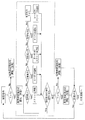
- FIG. 1 is a schematic configuration diagram of a compressed air storage power generation device according to an embodiment of the present invention.
- the flowchart which shows the whole flow of control of a control part.
- the flowchart corresponding to a long period variation in a charge command.
- the graph which shows the charging electric power with respect to time at the time of FIG.
- the flowchart corresponding to a short period variation in a charge command.
- the graph which shows the charging electric power with respect to time at the time of FIG.
- the flowchart corresponding to a long period fluctuation in a discharge command The graph which shows the discharge electric power with respect to time at the time of FIG.
- the flowchart corresponding to a short period fluctuation in a discharge command The graph which shows discharge electric power with respect to time at the time of FIG.
- the flowchart which shows discharge electric power with respect to time at the time of FIG.
- FIG. 1 is a schematic configuration diagram of a compressed air storage (CAES) power generation device 10 according to an embodiment of the present invention.
- the CAES power generation device 10 is for leveling output fluctuations when power is generated by using natural energy, and for performing output matching fluctuations in power demand.
- the CAES power generator 10 includes motors (electric motors) 2a to 2d and compressors 3a to 3d as a charging unit 11, and generators 4a to 4d and an expander as a discharging unit 12. It has 5a to 5d.
- the CAES power generation device 10 further includes pressure accumulators 6a and 6b for storing compressed air, injection side valves 7a to 7d provided in an air supply path between the pressure accumulators 6a and 6b and the compressors 3a to 3d, and pressure accumulators.
- Discharge side valves 8a to 8d provided in an air supply path between the parts 6a and 6b and the expanders 5a to 5d are provided.
- the CAES power generation device 10 cools the heat recovery/use unit 13, the charging unit 11, and the discharge unit 12 that recover the heat generated by the compressor into the heat medium and return the heat to the compressed air before being expanded by the expander.
- the cooling unit 14 and the control unit 15 that controls the CAES power generation device 10 are provided.
- Electric power generated by a power generator (not shown, which is located on the charging side in FIG. 1) using natural energy is supplied to the motors 2a to 2d electrically connected in parallel to each other through the charging line. It The electric power drives the motors 2a to 2d.
- the motors 2a to 2d are mechanically connected to the compressors 3a to 3d, respectively.
- the compressors 3a to 3d operate by driving the motors 2a to 2d, respectively.
- the compressors 3a to 3d compress the sucked air and send the compressed air to the pressure accumulators 6a and 6b. As a result, energy can be accumulated in the pressure accumulators 6a and 6b as compressed air.
- a power generator that uses natural energy uses energy that is constantly (or repetitively) replenished by natural power, such as wind power, sunlight, solar heat, wave or tidal power, running water or tidal power, and geothermal heat. You can target everything you do.
- natural power such as wind power, sunlight, solar heat, wave or tidal power, running water or tidal power, and geothermal heat.
- the pressure accumulators 6a and 6b a pressure accumulator tank, if the capacity is relatively large, a rock salt layer cavity, a tunnel of a closed mine, an underground cavity such as a sewer pipe/vertical hole, or a bag-shaped container submerged in water. Etc. can be used.
- the injection side valves 7a to 7d provided in the air supply path between the compressors 3a to 3d and the pressure accumulators 6a and 6b supply compressed air to any of the pressure accumulators 6a and 6b from the compressors 3a to 3d. Or switch.
- the compressed air accumulated in the pressure accumulators 6a and 6b is supplied to the expanders 5a to 5d.
- the expanders 5a to 5d are driven by this compressed air.
- Compressed air is supplied to each of the expanders 5a to 5d from each of the pressure accumulators 6a and 6b by the discharge side valves 8a to 8d provided in the air supply path between the pressure accumulators 6a and 6b and the expanders 5a to 5d. Or switch.
- the expanders 5a to 5d are electrically connected in parallel to each other and mechanically connected to the generators 4a to 4d, respectively.
- the power generators 4a to 4d operate by driving the expanders 5a to 5d to generate power.
- the generated electric power is supplied to the supply destination through the discharge line.
- the pressure accumulators 6a and 6b are provided with pressure sensors 9a and 9b for measuring the pressure inside the pressure accumulators 6a and 6b.
- the control unit 15 controls opening/closing of the injection side valves 7a to 7d and the discharge side valves 8a to 8d based on the charge/discharge command and the measured values of the pressure sensors 9a and 9b.
- the compressor 3a is a positive displacement type compressor, and the compressors 3b to 3d are speed type compressors.
- the displacement type compressor 3a is a screw type compressor
- the speed type compressors 3b to 3d are turbo type compressors.
- the expander 5a is a positive displacement expander
- the expanders 5b to 5d are speed expanders.
- the positive expander 5a is a screw expander and a speed expander.
- the expanders 5b to 5d are turbo expanders.
- the positive displacement type has a smaller capacity (low rotational speed) than the speed type and the efficiency is less likely to drop, stable power generation can be performed and the control range can be expanded even when the amount of compressed air stored in the pressure accumulating portions 6a and 6b is small. .. Further, the screw type is suitable for a relatively large capacity type among positive displacement types (others such as scroll type and rotary type).
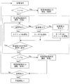
- FIG. 2 is a flowchart showing the overall control flow of the control unit 15.
- the control unit 15 determines whether to perform the long-cycle fluctuation correspondence or the short-cycle fluctuation correspondence, based on a charge or discharge command from the system. Specifically, when the charging command is received, the control unit 15 determines whether or not the fluctuation time T of the predicted fluctuation power exceeds the start/stop time Td of the turbo compressors 3b to 3d. We will respond to fluctuations, and if they do not exceed, we will respond to short-term fluctuations. Similarly, when receiving the discharge command, the control unit 15 determines whether or not the fluctuation time T of the predicted fluctuation power exceeds the start/stop time Td of the turbo expanders 5b to 5d. If it does not exceed, short-term fluctuations are dealt with. Note that the predicted fluctuating power corresponds to the fluctuating part of the power when the control unit 15 predicts the power in the charging or discharging command from the grid.
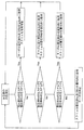
- FIG. 3 is a flowchart for dealing with long cycle fluctuations in a charging command
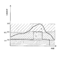
- FIG. 4 is a graph showing charging power with respect to time in FIG.
- the control unit 15 controls the predicted fluctuation power by controlling the number of turbo compressors 3b to 3d and the screw compressor 3a.
- the number of units control and the number of rotations control correspond. That is, since the fluctuation time T of the predicted fluctuation power exceeds the start/stop time Td of the turbo compressors 3b to 3d, the large capacity portion is supported by the turbo compressors 3b to 3d and the turbo compressors 3b to 3d.
- the screw type compressor 3a handles the variable portion that cannot be changed.
- the predicted fluctuating power amount is a fluctuating portion in the predicted value of the charging power.
- the charging power W is in the region I (0 ⁇ W ⁇ W1 (W1 is the operating range of the screw type compressor)
- one screw type compressor is started and the rotation speed is controlled.
- the charging power W is in the region II (W1 ⁇ W ⁇ W2 (W2 is the rated power of the turbo compressor)
- one turbo compressor is started at the rated value.
- the charging power W is in the region III (W2 ⁇ W ⁇ W3 (W3-W2 is the operating range of the screw type compressor))
- one turbo type compressor is started at the rated value, and one screw type compressor is activated. Start the stand and control the rotation speed.
- the charging power W is in the regions I to VII has been described as an example, but the number of regions is an example, and the present invention is not limited to this. Further, the rated capacity and number of screw type compressors and the rated capacity and number of turbo type compressors are also examples, and the present invention is not limited to these.
- FIG. 5 is a flow chart for dealing with short cycle fluctuations in a charging command
- FIG. 6 is a graph showing charging power with respect to time in FIG.
- the control unit 15 handles the predicted fluctuation power by controlling the number of screw type compressors 3a and controlling the number of revolutions. That is, since the fluctuation time T of the predicted fluctuation electric power is shorter than the start/stop time Td of the turbo compressors 3b to 3d, the turbo compressors 3b to 3d cannot respond in time, and therefore the fluctuation part is changed by the screw compressor 3a. Correspond.
- the charging power W is in the region I (0 ⁇ W ⁇ W1 (W1 is the operating range of the screw type compressor)
- one screw type compressor is started and the rotation speed is controlled.
- the charging power W is in the region II (W1 ⁇ W ⁇ W2 (W2 is the rated power of the turbo compressor)
- one turbo compressor is started at the rated value.
- the charging power W is in the region III (W2 ⁇ W ⁇ W3 (W3-W2 is the operating range of the screw type compressor))
- one turbo type compressor is started at the rated value, and one screw type compressor is activated. Start the stand and control the rotation speed.
- the injection side valves 7a to 7d in the charging command when the turbo compressors 3b to 3d and the screw compressor 3a are started, the injection side valves 7a and 7d are opened and the injection side valve 7b, 7c is closed.
- the injection valves 7a, 7c and 7d are opened and the injection valve 7b is closed.
- the injection side valve 7a is opened and the injection side valves 7b to 7d are closed.
- the discharge side valves 8a to 8d are closed in response to the charge command.
- FIG. 7 is a flowchart for dealing with long-cycle fluctuations in the discharge command
- FIG. 8 is a graph showing discharge power (demand power) with respect to time in FIG.
- the control unit 15 controls the predicted fluctuation power by controlling the number of turbo expanders 5b to 5d and the number of screw expanders. Control and rotation speed control correspond. That is, since the fluctuation time T of the predicted fluctuation power exceeds the start-stop time Td of the turbo expander, the turbo expander handles a large capacity portion, and the screw expander expands the fluctuation portion that cannot be supported by the turbo expander.
- the predicted fluctuating power amount is a fluctuating portion in the predicted value of the discharge power.
- the discharge power W is in the regions I to V has been described as an example, but the number of regions is an example, and the present invention is not limited to this.
- the rated power and the number of screw type expanders and the rated power and the number of turbo type expanders are also examples, and the present invention is not limited thereto.
- FIG. 9 is a flowchart for dealing with short cycle fluctuations in the discharge command
- FIG. 10 is a graph showing discharge power (demand power) with respect to time in FIG.
- the control unit 15 deals with the predicted fluctuation power by controlling the number of screw expanders and the rotational speed control. That is, since the fluctuation time T of the predicted fluctuation power is shorter than the start/stop time Td of the turbo expander, the turbo expansion machine cannot cope with it in time, so the fluctuation part is handled by the screw expansion machine.
- the discharge side valves 8a to 8d in the discharge command when the turbo expander and the screw expander are started, the discharge side valves 8a and 8d are opened and the discharge side valves 8b and 8c are closed. It When a plurality of turbo expanders are started, the discharge side valves 8a, 8c and 8d are opened and the discharge side valve 8b is closed. When only the screw expander is started, the discharge side valve 8a is opened and the discharge side valves 8b to 8d are closed. In addition, in response to the discharge command, the injection valves 7a to 7d are closed.
- FIG. 11 is a flowchart for selecting the pressure accumulating units 6a and 6b in the discharge command.
- the pressure sensor 9a measures the pressure in the pressure accumulator 6a
- the pressure sensor 9b measures the pressure in the pressure accumulator 6b.
- the control unit 15 preferentially uses the compressed air in the pressure accumulating unit in which the internal pressure P exceeds the set pressure Pd for the first expander and the internal pressure P for the second expander.
- the compressed air in the pressure accumulating portion below Pd is controlled to be preferentially used.
- the control unit 15 determines that the turbo expander is accumulating pressure.
- the parts 6a and 6b are preferentially used, and the screw type expander is also controlled so that the pressure accumulating parts 6a and 6b can be used.
- the control unit 15 gives priority to the pressure accumulating unit 6ab in the turbo expander.
- the screw type expander is controlled so that the pressure accumulator 6b is preferentially used.
- the control unit 15 preferentially controls the pressure accumulating unit 6b in the turbo expander.
- the screw type expander is controlled so that the pressure accumulator 6a is preferentially used.
- the control unit 15 causes the screw expander to operate the pressure accumulating sections 6a and 6b. It is used preferentially and the turbo expander is controlled to stop.
- the control unit 15 sets the predicted fluctuating power amount to the turbo type when the fluctuation time T of the predicted fluctuating power exceeds the start/stop time Td of the turbo compressors 3b to 3d.
- the control of the number of compressors 3b to 3d corresponds to the control of the number of screw compressors 3a and the rotation speed control
- the fluctuation time T of the predicted fluctuating power is equal to or shorter than the start/stop time Td of the turbo compressors 3b to 3d.
- the predicted fluctuating power is controlled so as to correspond to the number control and the rotation speed control of the screw compressor 3a.
- the control unit 15 sets the predicted fluctuating power to the turbo expansion.
- the fluctuation time T of the predicted variable power is equal to or shorter than the start/stop time Td of the turbo expanders 5b to 5d, which corresponds to the number control of the machines 5b to 5d and the number control and the rotation speed control of the screw type expander 5a.
- the predicted fluctuating electric power is controlled so as to correspond to the number control and the rotational speed control of the screw expander 5a.
- control unit 15 changes the control according to the magnitude of the fluctuation time of the predicted fluctuation power with respect to the start/stop time of the speed type compressors 3b to 3d/expanders 5b to 5d, thereby operating under efficient operating conditions.
- the compressors 3a to 3d and the expanders 5a to 5d that can be selected can be selected, and as a result, the operations of the compressors 3a to 3d and the expanders 5a to 5d can be efficiently controlled. Then, the operating efficiency of the CAES power generation device 10 can be improved.
- the pressure accumulated by each type of expander is preferentially used depending on the magnitude of the internal pressure of the pressure accumulators 6a and 6b with respect to the set pressure.
- the operation of the expander can be efficiently controlled. Specifically, compressed air is preferentially supplied to the speed-type expander from the pressure accumulator whose internal pressure P exceeds the set pressure Pd, and the internal pressure P is equal to or lower than the set pressure Pd. Compressed air is preferentially supplied to the positive displacement expander.
- the CAES power generator including one screw compressor, three turbo compressors, one screw expander, and three turbo expanders has been described as an example. It is sufficient that there is at least one compressor and at least one expander of each type. Further, the compressor and the expander of the same formula have been described on the assumption that they have the same performance, but the performance of the compressor and the expander of the same formula may be different.
- the turbo compressors 3b to 3d and the turbo expanders 5b to 5d have the same start/stop time Td, but the start/stop times are different between the turbo compressor and the turbo expander. May be. Further, the start and stop times may be different between the same compressor and expander. In that case, it is determined by the start/stop time of the compressor or expander to be started/stopped.
- the pressure accumulating unit includes the two pressure accumulating units 6a and 6b has been described as an example, but the number of the pressure accumulating units may be plural and may include three or more pressure accumulating units. Further, the capacities of the pressure accumulators may be the same or different.
Landscapes
- Engineering & Computer Science (AREA)
- Chemical & Material Sciences (AREA)
- Combustion & Propulsion (AREA)
- Mechanical Engineering (AREA)
- General Engineering & Computer Science (AREA)
- Power Engineering (AREA)
- Control Of Turbines (AREA)
- Supply And Distribution Of Alternating Current (AREA)
- Control Of Eletrric Generators (AREA)
Abstract
圧縮空気貯蔵発電装置(10)であって、電動機(2a~2d)と、圧縮機(3a~3d)と、蓄圧部(6a、6b)と、膨張機(5a~5d)と、発電機(4a~4d)と、制御部(15)と、を備え、圧縮機(3a~3d)は、速度型の第1圧縮機(3b~3d)と容積型の第2圧縮機(3a)を含み、膨張機(5a~5d)は、速度型の第1膨張機(5b~5d)と容積型の第2膨張機(5a)を含み、制御部(15)は、圧縮空気貯蔵発電装置(10)の充電時において、予測変動電力の変動時間が、第1圧縮機(3b~3d)の起動停止時間を超える場合、予測変動電力分を、第1圧縮機(3b~3d)の台数制御と、第2圧縮機(3a)の台数制御及び回転数制御で対応し、予測変動電力の変動時間が第1圧縮機(3b~3d)の起動停止時間以下である場合、予測変動電力分を、第2圧縮機(3a)の台数制御及び回転数制御で対応するよう制御し、及び/又は、制御部(15)は、圧縮空気貯蔵発電装置(10)の放電時において、予測変動電力の変動時間が、第1膨張機(5b~5d)の起動停止時間を超える場合、予測変動電力分を、第1膨張機(5b~5d)の台数制御と、第2膨張機(5a)の台数制御及び回転数制御で対応し、予測変動電力の変動時間が第1膨張機(5b~5d)の起動停止時間以下である場合、予測変動電力分を、第2膨張機(5a)の台数制御及び回転数制御で対応するよう制御する。
Description
本発明は、圧縮空気貯蔵発電装置及び圧縮空気貯蔵発電方法に関する。
風力発電や太陽光発電などの自然エネルギーを利用した発電は、気象条件に依存するため、出力が安定しないことがある。このため、圧縮空気貯蔵(CAES:compressed air energy storage)システム等のエネルギー貯蔵システムを利用して、出力を平準化することが行われている。
従来、圧縮空気貯蔵(CAES)発電装置は、電力プラントのオフピーク時間中に圧縮機を駆動して電気エネルギーを圧縮空気として貯蔵し、高電力需要時間中に圧縮空気により膨張機を駆動して発電機を作動させ、電気エネルギーを生成するのが一般的である。
ここで、自然エネルギーを利用した発電には、長周期と短周期の出力変動がある。例えば、太陽光を利用した発電の場合、長周期の出力変動要因は日中と夜間の違い等であり、短周期の出力変動要因は一時的に太陽が雲に隠れる場合等である。一方、風力を利用した発電の場合、長周期の出力変動要因は強風や無風による発電停止の場合等であり、短周期の出力変動は風速の変動による場合等である。
そして、特許文献1では、長周期と短周期の両方の変動電力に対応できる圧縮空気貯蔵発電装置が開示されている。
ここで、特許文献1では、圧縮空気貯蔵発電装置において、長周期と短周期の両方の変動電力に対応するため、異なる型式の圧縮機及び膨張機を併用することについては開示されているが、予測変動電力に応じてそれらの圧縮機及び膨張機をどのように制御するかについては、開示されていない。
そこで本発明では、予測変動電力に応じて、圧縮機及び膨張機の運転を効率的に制御できる圧縮空気貯蔵発電装置及び圧縮空気貯蔵発電方法を提供することを目的とする。
本発明の第1の態様は、圧縮空気貯蔵発電装置であって、
入力電力により駆動される電動機と、
前記電動機と機械的に接続され、空気を圧縮する圧縮機と、
前記圧縮機と流体的に接続され、前記圧縮機により圧縮された圧縮空気を貯蔵する蓄圧部と、
前記蓄圧部と流体的に接続され、前記蓄圧部から供給される圧縮空気によって駆動される膨張機と、
前記膨張機と機械的に接続された発電機と、
前記圧縮空気貯蔵発電装置を制御する制御部と、を備え、
前記圧縮機は、速度型の第1圧縮機と容積型の第2圧縮機を含み、
前記膨張機は、速度型の第1膨張機と容積型の第2膨張機を含み、
前記制御部は、前記圧縮空気貯蔵発電装置の充電時において、予測変動電力の変動時間が、第1圧縮機の起動停止時間を超える場合、予測変動電力分を、第1圧縮機の台数制御と、第2圧縮機の台数制御及び回転数制御で対応し、予測変動電力の変動時間が第1圧縮機の起動停止時間以下である場合、予測変動電力分を、第2圧縮機の台数制御及び回転数制御で対応するよう制御し、及び/又は、
前記制御部は、前記圧縮空気貯蔵発電装置の放電時において、予測変動電力の変動時間が、第1膨張機の起動停止時間を超える場合、予測変動電力分を、第1膨張機の台数制御と、第2膨張機の台数制御及び回転数制御で対応し、予測変動電力の変動時間が第1膨張機の起動停止時間以下である場合、予測変動電力分を、第2膨張機の台数制御及び回転数制御で対応するよう制御する。
入力電力により駆動される電動機と、
前記電動機と機械的に接続され、空気を圧縮する圧縮機と、
前記圧縮機と流体的に接続され、前記圧縮機により圧縮された圧縮空気を貯蔵する蓄圧部と、
前記蓄圧部と流体的に接続され、前記蓄圧部から供給される圧縮空気によって駆動される膨張機と、
前記膨張機と機械的に接続された発電機と、
前記圧縮空気貯蔵発電装置を制御する制御部と、を備え、
前記圧縮機は、速度型の第1圧縮機と容積型の第2圧縮機を含み、
前記膨張機は、速度型の第1膨張機と容積型の第2膨張機を含み、
前記制御部は、前記圧縮空気貯蔵発電装置の充電時において、予測変動電力の変動時間が、第1圧縮機の起動停止時間を超える場合、予測変動電力分を、第1圧縮機の台数制御と、第2圧縮機の台数制御及び回転数制御で対応し、予測変動電力の変動時間が第1圧縮機の起動停止時間以下である場合、予測変動電力分を、第2圧縮機の台数制御及び回転数制御で対応するよう制御し、及び/又は、
前記制御部は、前記圧縮空気貯蔵発電装置の放電時において、予測変動電力の変動時間が、第1膨張機の起動停止時間を超える場合、予測変動電力分を、第1膨張機の台数制御と、第2膨張機の台数制御及び回転数制御で対応し、予測変動電力の変動時間が第1膨張機の起動停止時間以下である場合、予測変動電力分を、第2膨張機の台数制御及び回転数制御で対応するよう制御する。
前記構成によれば、速度型の圧縮機/膨張機の起動停止時間に対する予測変動電力の変動時間の大小に応じて制御を変えることによって、効率のよい運転条件で運転できる圧縮機及び膨張機を選択でき、その結果、圧縮機及び膨張機の運転を効率的に制御できる。
前記第1の態様は、さらに、次のような構成を備えるのが好ましい。
(1)前記蓄圧部は、互いに分離された複数の蓄圧部を含み、
複数の前記蓄圧部は、第1圧縮機、第2圧縮機、第1膨張機及び第2膨張機とそれぞれ接続されており、その内部圧力が監視されている。
複数の前記蓄圧部は、第1圧縮機、第2圧縮機、第1膨張機及び第2膨張機とそれぞれ接続されており、その内部圧力が監視されている。
(2)前記構成(1)において、前記制御部は、第1膨張機は内部圧力が設定圧力を超える蓄圧部の圧縮空気を優先的に使用し、第2膨張機は内部圧力が設定圧力を下回る蓄圧部の圧縮空気を優先的に使用するよう制御する。
(3)第1圧縮機は、ターボ式圧縮機であり、
第1膨張機は、ターボ式膨張機であり、
第2圧縮機は、スクリュ式圧縮機であり、
第2膨張機は、スクリュ式膨張機である。
第1膨張機は、ターボ式膨張機であり、
第2圧縮機は、スクリュ式圧縮機であり、
第2膨張機は、スクリュ式膨張機である。
前記構成(1)によれば、複数の蓄圧部を設け、蓄圧部の内部圧力を監視することによって、圧縮機及び膨張機がより効率的に運転できる蓄圧部を選択することができる。
速度型の膨張機と容積型の膨張機とでは最適運転条件が異なるため、前記構成(2)によれば、設定圧力に対する蓄圧部の内部圧力の大小によって、各型の膨張機が優先的に使用する蓄圧部を選択することによって、膨張機の運転を効率的に制御できる。
前記構成(3)によれば、速度型の圧縮機/膨張機にターボ式を採用し、容積型の圧縮機/膨張機にスクリュ式を採用することによって、運転制御を容易に行うことができる。また、容積型にスクリュ式を採用することによって、比較的大容量の圧縮、膨張に対応できる。
本発明の第2の態様は、入力電力により駆動される電動機と、
前記電動機と機械的に接続され、空気を圧縮する圧縮機と、
前記圧縮機と流体的に接続され、前記圧縮機により圧縮された圧縮空気を貯蔵する蓄圧部と、
前記蓄圧部と流体的に接続され、前記蓄圧部から供給される圧縮空気によって駆動される膨張機と、
前記膨張機と機械的に接続された発電機と、を備え、
前記圧縮機は、速度型の第1圧縮機と容積型の第2圧縮機を含み、
前記膨張機は、速度型の第1膨張機と容積型の第2膨張機を含む、圧縮空気貯蔵発電装置の圧縮空貯蔵発電方法であって、
前記圧縮空気貯蔵発電装置の充電時において、予測変動電力の変動時間が、第1圧縮機の起動停止時間を超える場合、予測変動電力分を、第1圧縮機の台数制御と、第2圧縮機の台数制御及び回転数制御で対応し、予測変動電力の変動時間が第1圧縮機の起動停止時間以下である場合、予測変動電力分を、第2圧縮機の台数制御及び回転数制御で対応するよう制御し、及び/又は、
前記圧縮空気貯蔵発電装置の放電時において、予測変動電力の変動時間が、第1膨張機の起動停止時間を超える場合、予測変動電力分を、第1膨張機の台数制御と、第2膨張機の台数制御及び回転数制御で対応し、予測変動電力の変動時間が第1膨張機の起動停止時間以下である場合、予測変動電力分を、第2膨張機の台数制御及び回転数制御で対応するよう制御する。
前記電動機と機械的に接続され、空気を圧縮する圧縮機と、
前記圧縮機と流体的に接続され、前記圧縮機により圧縮された圧縮空気を貯蔵する蓄圧部と、
前記蓄圧部と流体的に接続され、前記蓄圧部から供給される圧縮空気によって駆動される膨張機と、
前記膨張機と機械的に接続された発電機と、を備え、
前記圧縮機は、速度型の第1圧縮機と容積型の第2圧縮機を含み、
前記膨張機は、速度型の第1膨張機と容積型の第2膨張機を含む、圧縮空気貯蔵発電装置の圧縮空貯蔵発電方法であって、
前記圧縮空気貯蔵発電装置の充電時において、予測変動電力の変動時間が、第1圧縮機の起動停止時間を超える場合、予測変動電力分を、第1圧縮機の台数制御と、第2圧縮機の台数制御及び回転数制御で対応し、予測変動電力の変動時間が第1圧縮機の起動停止時間以下である場合、予測変動電力分を、第2圧縮機の台数制御及び回転数制御で対応するよう制御し、及び/又は、
前記圧縮空気貯蔵発電装置の放電時において、予測変動電力の変動時間が、第1膨張機の起動停止時間を超える場合、予測変動電力分を、第1膨張機の台数制御と、第2膨張機の台数制御及び回転数制御で対応し、予測変動電力の変動時間が第1膨張機の起動停止時間以下である場合、予測変動電力分を、第2膨張機の台数制御及び回転数制御で対応するよう制御する。
前記構成によれば、速度型の圧縮機/膨張機の起動停止時間に対する予測変動電力の変動時間の大小に応じて制御を変えることによって、圧縮機及び膨張機の運転を効率的に制御できる。
本発明によると、予測変動電力に応じて、圧縮機及び膨張機の運転を効率的に制御できる圧縮空気貯蔵発電装置及び圧縮空気貯蔵発電方法を提供できる。
以下、添付図面を参照して、本発明の実施形態を説明する。
図1は、本発明の実施形態に係る圧縮空気貯蔵(CAES:compressed air energy storage)発電装置10の概略構成図である。このCAES発電装置10は、自然エネルギーを利用して発電する場合の出力変動を平準化すると共に、電力需要の変動に合わせた出力を行うためのものである。
図1に示されるように、CAES発電装置10は、充電ユニット11として、モータ(電動機)2a~2d、圧縮機3a~3dを備えており、放電ユニット12として、発電機4a~4d、膨張機5a~5dを備えている。そして、CAES発電装置10は、さらに、圧縮空気を貯蔵する蓄圧部6a、6b、蓄圧部6a、6bと圧縮機3a~3dとの間の空気供給路に設けられる注入側弁7a~7d、蓄圧部6a、6bと膨張機5a~5dとの間の空気供給路に設けられる排出側弁8a~8dを備えている。また、CAES発電装置10は、圧縮機で発生した熱を熱媒に回収し、膨張機で膨張する前の圧縮空気に熱を戻す熱回収・利用ユニット13、充電ユニット11及び放電ユニット12を冷却する冷却ユニット14及びCAES発電装置10を制御する制御部15を備えている。
自然エネルギーを利用する発電装置(図示せず、図1の充電側に位置する)により発電された電力は、充電ラインを通って、互いに電気的に並列に接続されたモータ2a~2dに供給される。この電力により、モータ2a~2dが駆動される。モータ2a~2dは、圧縮機3a~3dに機械的にそれぞれ接続されている。圧縮機3a~3dは、モータ2a~2dを駆動させることでそれぞれ作動する。圧縮機3a~3dは、吸引した空気を圧縮し、蓄圧部6a、6bへ圧送する。これにより、蓄圧部6a、6bに圧縮空気としてエネルギーを蓄積できる。なお、自然エネルギーを利用する発電装置は、風力、太陽光、太陽熱、波力又は潮力、流水又は潮汐、及び地熱等、自然の力で定常的(もしくは反復的)に補充されるエネルギーを利用する全てを対象とすることができる。また、蓄圧部6a、6bとしては、蓄圧タンクや、容量が比較的大きい場合、岩塩層空洞、休鉱山の坑道、下水配管・縦孔等の地下空洞、又は、水中に沈めた袋状の容器等を使用することができる。
圧縮機3a~3dと蓄圧部6a、6bとの間の空気供給路に設けられた注入側弁7a~7dにより、各圧縮機3a~3dからいずれの蓄圧部6a、6bに圧縮空気を供給するかを切り替える。
蓄圧部6a、6bに蓄積された圧縮空気は、膨張機5a~5dに供給される。この圧縮空気により膨張機5a~5dは駆動される。蓄圧部6a、6bと膨張機5a~5dとの間の空気供給路に設けられた排出側弁8a~8dにより、各蓄圧部6a、6bからいずれの膨張機5a~5dに圧縮空気を供給するか切り替える。
膨張機5a~5dは、互いに電気的に並列に接続されており、発電機4a~4dに機械的にそれぞれ接続されている。発電機4a~4dは、膨張機5a~5dを駆動させることで作動し、発電する。発電された電力は、放電ラインを通って、供給先に供給される。
蓄圧部6a、6bには、蓄圧部6a、6b内の圧力を測定する圧力センサ9a、9bが設けられている。制御部15は、充放電指令及び圧力センサ9a、9bの測定値に基づいて、注入側弁7a~7d及び排出側弁8a~8dの開閉を制御する。
本実施形態では、圧縮機3aは容積型の圧縮機であり、圧縮機3b~3dは速度型の圧縮機である。具体的には、容積型の圧縮機3aはスクリュ式圧縮機であり、速度型の圧縮機3b~3dはターボ式圧縮機である。また、膨張機5aは容積型の膨張機であり、膨張機5b~5dは速度型の膨張機である、具体的には、容積型の膨張機5aはスクリュ式膨張機であり、速度型の膨張機5b~5dはターボ式膨張機である。なお、容積型は速度型に比べて小容量(低回転数)でも効率が落ちにくいので、蓄圧部6a、6bに蓄えられた圧縮空気が少ない場合でも安定した発電ができ、制御範囲を拡張できる。また、スクリュ式は、容積型(その他、スクロール式やロータリー式等)の中でも比較的大容量のものに適している。
次に、制御部15によるCAES発電装置10の制御について説明する。
図2は、制御部15の制御の全体フローを示すフローチャートである。図2に示されるように、系統からの充電又は放電の指令に基づき、制御部15は、長周期変動対応又は短周期変動対応を行うか判断する。具体的には、充電指令を受けると、制御部15は、予測変動電力の変動時間Tがターボ式圧縮機3b~3dの起動停止時間Tdを超えるかどうかを判断し、超える場合には長周期変動対応を行い、超えない場合には短周期変動対応を行う。同様に、放電指令を受けると、制御部15は、予測変動電力の変動時間Tがターボ式膨張機5b~5dの起動停止時間Tdを超えるかどうかを判断し、超える場合には長周期変動対応を行い、超えない場合には短周期変動対応を行う。なお、予測変動電力とは、制御部15が系統からの充電又は放電の指令における電力を予測する際の、電力の変動部分に対応する。
[CAES発電装置10の充電時]
図3は、充電指令における長周期変動対応のフローチャートであり、図4は、図3のときの時間に対する充電電力を示すグラフである。図3及び図4に示されるように、充電指令における長周期変動対応の場合、制御部15は、予測変動電力分を、ターボ式圧縮機3b~3dの台数制御と、スクリュ式圧縮機3aの台数制御及び回転数制御で対応する。すなわち、予測変動電力の変動時間Tがターボ式圧縮機3b~3dの起動停止時間Tdを超えるので、大容量部分をターボ式圧縮機3b~3dで対応し、ターボ式圧縮機3b~3dで対応できない変動部分についてスクリュ式圧縮機3aで対応する。ここで、予測変動電力分とは、充電電力の予測値の内の変動部分である。
図3は、充電指令における長周期変動対応のフローチャートであり、図4は、図3のときの時間に対する充電電力を示すグラフである。図3及び図4に示されるように、充電指令における長周期変動対応の場合、制御部15は、予測変動電力分を、ターボ式圧縮機3b~3dの台数制御と、スクリュ式圧縮機3aの台数制御及び回転数制御で対応する。すなわち、予測変動電力の変動時間Tがターボ式圧縮機3b~3dの起動停止時間Tdを超えるので、大容量部分をターボ式圧縮機3b~3dで対応し、ターボ式圧縮機3b~3dで対応できない変動部分についてスクリュ式圧縮機3aで対応する。ここで、予測変動電力分とは、充電電力の予測値の内の変動部分である。
具体的には、充電電力Wが領域I(0<W<W1(W1はスクリュ式圧縮機の運転範囲))である場合、スクリュ式圧縮機を1台起動させ、それを回転数制御する。充電電力Wが領域II(W1<W<W2(W2はターボ式圧縮機の定格電力))である場合、ターボ式圧縮機を定格で1台起動させる。充電電力Wが領域III(W2<W<W3(W3-W2はスクリュ式圧縮機の運転範囲))である場合、ターボ式圧縮機を定格で1台起動させ、さらに、スクリュ式圧縮機を1台起動させ、それを回転数制御する。充電電力Wが領域IV(W3<W<W4(W4はターボ式圧縮機の2台の定格電力))である場合、ターボ式圧縮機を定格で2台起動させる。充電電力Wが領域V(W4<W<W5(W5-W4はスクリュ式圧縮機の運転範囲))である場合、ターボ式圧縮機を定格で2台起動させ、さらに、スクリュ式圧縮機を1台起動させ、それを回転数制御する。充電電力Wが領域VI(W5<W<W6(W6はターボ式圧縮機の3台の定格電力))である場合、ターボ式圧縮機を定格で3台起動させる。充電電力Wが領域VII(W6<W<W7(W7-W6はスクリュ式圧縮機の運転範囲))である場合、ターボ式圧縮機を定格で3台起動させ、さらに、スクリュ式圧縮機を1台起動させ、それを回転数制御する。なお、ターボ式圧縮機の運転では、制御部15は、電力変化を予測し、急速立ち上げ、急停止をしないように制御する。また、長周期変動対応を行っている場合においても、次の予測において、予測変動電力の変動時間Tがターボ式圧縮機の起動停止時間Tdを超えない場合には短周期変動対応を行うように変更する。なお、ここでは、充電電力Wが領域I~VIIにある場合を例に説明したが、領域の数は一例であり、これに限定されるものではない。また、スクリュ式圧縮機の定格容量、台数及びターボ式圧縮機の定格容量、台数も一例であり、これに限定されるものではない。
図5は、充電指令における短周期変動対応のフローチャートであり、図6は、図5のときの時間に対する充電電力を示すグラフである。図5及び図6に示されるように、充電指令における短周期変動対応の場合、制御部15は、予測変動電力分を、スクリュ式圧縮機3aの台数制御及び回転数制御で対応する。すなわち、予測変動電力の変動時間Tがターボ式圧縮機3b~3dの起動停止時間Tdを下回るので、ターボ式圧縮機3b~3dでは対応が間に合わないことから、変動部分についてスクリュ式圧縮機3aで対応する。
具体的には、充電電力Wが領域I(0<W<W1(W1はスクリュ式圧縮機の運転範囲))である場合、スクリュ式圧縮機を1台起動させ、それを回転数制御する。充電電力Wが領域II(W1<W<W2(W2はターボ式圧縮機の定格電力))である場合、ターボ式圧縮機を定格で1台起動させる。充電電力Wが領域III(W2<W<W3(W3-W2はスクリュ式圧縮機の運転範囲))である場合、ターボ式圧縮機を定格で1台起動させ、さらに、スクリュ式圧縮機を1台起動させ、それを回転数制御する。なお、短周期変動対応を行っている場合においても、次の予測において、予測変動電力の変動時間Tがターボ式圧縮機の起動停止時間Tdを超える場合には、長周期変動対応を行うように変更する。なお、ここでは、充電電力Wが領域I~IIIにある場合を例に説明したが、領域の数は一例であり、これに限定されるものではない。また、スクリュ式圧縮機の定格電力、台数及びターボ式圧縮機の定格電力、台数も一例であり、これに限定されるものではない。
充電指令における注入側弁7a~7dの開閉状態については、ターボ式圧縮機3b~3dとスクリュ式圧縮機3aとが起動される場合、注入側弁7a、7dが開放され、注入側弁7b、7cは閉止される。ターボ式圧縮機3b~3dが複数台起動される場合、注入側弁7a、7c及び7dが開放され、注入側弁7bは閉止される。スクリュ式圧縮機3aのみが起動される場合、注入側弁7aが開放され、注入側弁7b~7dは閉止される。なお、充電指令においては、排出側弁8a~8dは閉止される。
[CAES発電装置10の放電時]
図7は、放電指令における長周期変動対応のフローチャートであり、図8は、図7のときの時間に対する放電電力(需要電力)を示すグラフである。図7及び図8に示されるように、放電指令における長周期変動対応の場合、制御部15は、予測変動電力分を、ターボ式膨張機5b~5dの台数制御と、スクリュ式膨張機の台数制御及び回転数制御で対応する。すなわち、予測変動電力の変動時間Tがターボ式膨張機の起動停止時間Tdを超えるので、大容量部分をターボ式膨張機で対応し、ターボ式膨張機で対応できない変動部分についてスクリュ式膨張機で対応する。ここで、予測変動電力分とは、放電電力の予測値の内の変動部分である。
図7は、放電指令における長周期変動対応のフローチャートであり、図8は、図7のときの時間に対する放電電力(需要電力)を示すグラフである。図7及び図8に示されるように、放電指令における長周期変動対応の場合、制御部15は、予測変動電力分を、ターボ式膨張機5b~5dの台数制御と、スクリュ式膨張機の台数制御及び回転数制御で対応する。すなわち、予測変動電力の変動時間Tがターボ式膨張機の起動停止時間Tdを超えるので、大容量部分をターボ式膨張機で対応し、ターボ式膨張機で対応できない変動部分についてスクリュ式膨張機で対応する。ここで、予測変動電力分とは、放電電力の予測値の内の変動部分である。
具体的には、放電電力Wが領域I(0<W<W1(W1はスクリュ式膨張機の運転範囲))である場合、スクリュ式膨張機を1台起動させ、それを回転数制御する。放電電力Wが領域II(W1<W<W2(W2はターボ式膨張機の定格電力))である場合、ターボ式膨張機を定格で1台起動させる。放電電力Wが領域III(W2<W<W3(W3-W2はスクリュ式膨張機の運転範囲))である場合、ターボ式膨張機を定格で1台起動させ、さらに、スクリュ式膨張機を1台起動させ、それを回転数制御する。充電電力Wが領域IV(W3<W<W4(W4はターボ式膨張機の2台の定格電力))である場合、ターボ式膨張機を定格で2台起動させる。充電電力Wが領域V(W4<W<W5(W5-W4はスクリュ式膨張機の運転範囲))である場合、ターボ式膨張機を定格で2台起動させ、さらに、スクリュ式膨張機を1台起動させ、それを回転数制御する。なお、ターボ式膨張機の運転では、制御部15は、電力変化を予測し、急速立ち上げ、急停止をしないように制御する。また、長周期変動対応を行っている場合においても、次の予測において、予測変動電力の変動時間Tがターボ式膨張機の起動停止時間Tdを超えない場合には短周期変動対応を行うように変更する。なお、ここでは、放電電力Wが領域I~Vにある場合を例に説明したが、領域の数は一例であり、これに限定されるものではない。また、スクリュ式膨張機の定格電力、台数及びターボ式膨張機の定格電力、台数も一例であり、これに限定されるものではない。
図9は、放電指令における短周期変動対応のフローチャートであり、図10は、図9のときの時間に対する放電電力(需要電力)を示すグラフである。図9及び図10に示されるように、放電指令における短周期変動対応の場合、制御部15は、予測変動電力分を、スクリュ式膨張機の台数制御及び回転数制御で対応する。すなわち、予測変動電力の変動時間Tがターボ式膨張機の起動停止時間Tdを下回るので、ターボ式膨張機では対応が間に合わないことから、変動部分についてスクリュ式膨張機で対応する。
具体的には、放電電力Wが領域I(0<W<W1(W1はスクリュ式膨張機の運転範囲))である場合、スクリュ式膨張機を1台起動させ、それを回転数制御する。放電電力Wが領域II(W1<W<W2(W2はターボ式膨張機の定格電力))である場合、ターボ式膨張機を定格で1台起動させる。放電電力Wが領域III(W2<W<W3(W3-W2はスクリュ式圧縮機の運転範囲))である場合、ターボ式圧縮機を定格で1台起動させ、さらに、スクリュ式圧縮機を1台起動させ、それを回転数制御する。なお、短周期変動対応を行っている場合においても、次の予測において、予測変動電力の変動時間Tがターボ式膨張機の起動停止時間Tdを超える場合には、長周期変動対応を行うように変更する。なお、ここでは、放電電力Wが領域I~IIIにある場合を例に説明したが、領域の数は一例であり、これに限定されるものではない。また、スクリュ式膨張機の定格容量、台数及びターボ式膨張機の定格容量、台数も一例であり、これに限定されるものではない。
放電指令における排出側弁8a~8dの開閉状態については、ターボ式膨張機とスクリュ式膨張機とが起動される場合、排出側弁8a、8dが開放され、排出側弁8b、8cは閉止される。ターボ式膨張機が複数台起動される場合、排出側弁8a、8c及び8dが開放され、排出側弁8bは閉止される。スクリュ式膨張機のみが起動される場合、排出側弁8aが開放され、排出側弁8b~8dは閉止される。なお、放電指令においては、注入側弁7a~7dは閉止される。
図11は、放電指令における蓄圧部6a、6bの選択のフローチャートである。圧力センサ9aは、蓄圧部6a内の圧力を測定しており、圧力センサ9bは、蓄圧部6b内の圧力を測定している。図11に示されるように、制御部15は、第1膨張機は内部圧力Pが設定圧力Pdを超える蓄圧部の圧縮空気を優先的に使用し、第2膨張機は内部圧力Pが設定圧力Pdを下回る蓄圧部の圧縮空気を優先的に使用するよう制御する。
具体的には、制御部15は、蓄圧部6aの内圧Pが設定圧力Pdを超えており、さらに、蓄圧部6bの内圧Pも設定圧力Pdを超えている場合、ターボ式膨張機は、蓄圧部6a、6bを優先的に使用し、スクリュ式膨張機も蓄圧部6a、6bを使用可能となるよう制御する。また、制御部15は、蓄圧部6aの内圧Pが設定圧力Pdを超えており、さらに、蓄圧部6bの内圧Pは設定圧力Pd以下である場合、ターボ式膨張機は、蓄圧部6abを優先的に使用し、スクリュ式膨張機は蓄圧部6bを優先的に使用するよう制御する。
制御部15は、蓄圧部6aの内圧Pが設定圧力Pd以下であり、さらに、蓄圧部6bの内圧Pが設定圧力Pdを超えている場合、ターボ式膨張機は、蓄圧部6bを優先的に使用し、スクリュ式膨張機は蓄圧部6aを優先的に使用するよう制御する。また、制御部15は、蓄圧部6aの内圧Pが設定圧力Pd以下であり、さらに、蓄圧部6bの内圧Pも設定圧力Pd以下である場合、スクリュ式膨張機は、蓄圧部6a、6bを優先的に使用し、ターボ式膨張機は停止させるよう制御する。
前記構成のCAES発電装置2によれば、次のような効果を発揮できる。
(1)制御部15は、CAES発電装置10の充電時において、予測変動電力の変動時間Tが、ターボ式圧縮機3b~3dの起動停止時間Tdを超える場合、予測変動電力分を、ターボ式圧縮機3b~3dの台数制御と、スクリュ式圧縮機3aの台数制御及び回転数制御で対応し、予測変動電力の変動時間Tがターボ式圧縮機3b~3dの起動停止時間Td以下である場合、予測変動電力分を、スクリュ式圧縮機3aの台数制御及び回転数制御で対応するよう制御する。また、制御部15は、CAES発電装置10の放電時において、予測変動電力の変動時間Tが、ターボ式膨張機5b~5dの起動停止時間Tdを超える場合、予測変動電力分を、ターボ式膨張機5b~5dの台数制御と、スクリュ式膨張機5aの台数制御及び回転数制御で対応し、予測変動電力の変動時間Tがターボ式膨張機5b~5dの起動停止時間Td以下である場合、予測変動電力分を、スクリュ式膨張機5aの台数制御及び回転数制御で対応するよう制御する。すなわち、制御部15が、速度型の圧縮機3b~3d/膨張機5b~5dの起動停止時間に対する予測変動電力の変動時間の大小に応じて制御を変えることによって、効率のよい運転条件で運転できる圧縮機3a~3d及び膨張機5a~5dを選択でき、その結果、圧縮機3a~3d及び膨張機5a~5dの運転を効率的に制御できる。そして、CAES発電装置10の運転効率を向上させることができる。
(2)複数の蓄圧部6a、6bを設け、圧力センサ9a、9bによって、蓄圧部6a、6bの内部圧力を監視するようになっているので、圧縮機及び膨張機がより効率的に運転できる蓄圧部6a、6bを選択することができる。
(3)速度型の膨張機と容積型の膨張機とでは最適運転条件が異なるため、設定圧力に対する蓄圧部6a、6bの内部圧力の大小によって、各型の膨張機が優先的に使用する蓄圧部6a、6bを選択することによって、膨張機の運転を効率的に制御できる。具体的には、内部圧力Pが設定圧力Pdを超える蓄圧部から、速度型の膨張機に対して、優先的に圧縮空気を供給し、内部圧力Pが設定圧力Pd以下である蓄圧部から、容積型の膨張機に対して、優先的に圧縮空気を供給する。
(4)速度型の圧縮機/膨張機にターボ式を採用し、容積型の圧縮機/膨張機にスクリュ式を採用することによって、運転制御を容易に行うことができる。また、容積型にスクリュ式を採用することによって、その他の容積型であるスクロール式やロータリー式と比べて、比較的大容量の圧縮、膨張に対応できる。
上記実施形態では、スクリュ式圧縮機を1台、ターボ式圧縮機を3台、スクリュ式膨張機を1台、ターボ式膨張機を3台備えるCAES発電装置を例として説明したが、各式の圧縮機が1台以上、各式の膨張機が1台以上あればよい。また、同式の圧縮機及び膨張機は、同じ性能のものを前提として説明したが、同式の圧縮機及び膨張機の性能は異なっていてもよい。
上記実施形態では、ターボ式圧縮機3b~3dとターボ式膨張機5b~5dの起動停止時間Tdを同じとして説明しているが、ターボ式圧縮機とターボ式膨張機とで起動停止時間が異なっていてもよい。また、同じ圧縮機、膨張機間でも起動停止時間が異なっていてもよい。その場合は、起動停止対象となる圧縮機、膨張機の起動停止時間で判断される。
上記実施形態では、蓄圧部として2つの蓄圧部6a、6bを含むものを例として説明しているが、蓄圧部の数は複数であればよく、3以上の蓄圧部を含んでもよい。また、各蓄圧部の容量は同じでもよく、異なっていてもよい。
本発明は、上記実施形態で説明された構成には限定されず、特許請求の範囲に記載された内容を逸脱することなく、当業者が考え得る各種変形例を含むことができる。
2a、2b、2c、2d モータ
3a 第2圧縮機(スクリュ式圧縮機)
3b 第1圧縮機(ターボ式圧縮機)
3c 第1圧縮機(ターボ式圧縮機)
3d 第1圧縮機(ターボ式圧縮機)
4a、4b、4c、4d 発電機
5a 第2膨張機(スクリュ式膨張機)
5b 第1膨張機(ターボ式膨張機)
5c 第1膨張機(ターボ式膨張機)
5d 第1膨張機(ターボ式膨張機)
6a 蓄圧部
6b 蓄圧部
7a、7b、7c、7d 注入側弁
8a、8b、8c、8d 排出側弁
9a 圧力センサ
9b 圧力センサ
10 CAES発電装置
11 充電ユニット
12 放電ユニット
13 熱回収・利用ユニット
14 冷却ユニット
15 制御部
3a 第2圧縮機(スクリュ式圧縮機)
3b 第1圧縮機(ターボ式圧縮機)
3c 第1圧縮機(ターボ式圧縮機)
3d 第1圧縮機(ターボ式圧縮機)
4a、4b、4c、4d 発電機
5a 第2膨張機(スクリュ式膨張機)
5b 第1膨張機(ターボ式膨張機)
5c 第1膨張機(ターボ式膨張機)
5d 第1膨張機(ターボ式膨張機)
6a 蓄圧部
6b 蓄圧部
7a、7b、7c、7d 注入側弁
8a、8b、8c、8d 排出側弁
9a 圧力センサ
9b 圧力センサ
10 CAES発電装置
11 充電ユニット
12 放電ユニット
13 熱回収・利用ユニット
14 冷却ユニット
15 制御部
Claims (5)
- 圧縮空気貯蔵発電装置であって、
入力電力により駆動される電動機と、
前記電動機と機械的に接続され、空気を圧縮する圧縮機と、
前記圧縮機と流体的に接続され、前記圧縮機により圧縮された圧縮空気を貯蔵する蓄圧部と、
前記蓄圧部と流体的に接続され、前記蓄圧部から供給される圧縮空気によって駆動される膨張機と、
前記膨張機と機械的に接続された発電機と、
前記圧縮空気貯蔵発電装置を制御する制御部と、を備え、
前記圧縮機は、速度型の第1圧縮機と容積型の第2圧縮機を含み、
前記膨張機は、速度型の第1膨張機と容積型の第2膨張機を含み、
前記制御部は、前記圧縮空気貯蔵発電装置の充電時において、予測変動電力の変動時間が、第1圧縮機の起動停止時間を超える場合、予測変動電力分を、第1圧縮機の台数制御と、第2圧縮機の台数制御及び回転数制御で対応し、予測変動電力の変動時間が第1圧縮機の起動停止時間以下である場合、予測変動電力分を、第2圧縮機の台数制御及び回転数制御で対応するよう制御し、及び/又は、
前記制御部は、前記圧縮空気貯蔵発電装置の放電時において、予測変動電力の変動時間が、第1膨張機の起動停止時間を超える場合、予測変動電力分を、第1膨張機の台数制御と、第2膨張機の台数制御及び回転数制御で対応し、予測変動電力の変動時間が第1膨張機の起動停止時間以下である場合、予測変動電力分を、第2膨張機の台数制御及び回転数制御で対応するよう制御する、圧縮空気貯蔵発電装置。 - 前記蓄圧部は、互いに分離された複数の蓄圧部を含み、
複数の前記蓄圧部は、第1圧縮機、第2圧縮機、第1膨張機及び第2膨張機とそれぞれ接続されており、その内部圧力が監視されている、請求項1記載の圧縮空気貯蔵発電装置。 - 前記制御部は、第1膨張機は内部圧力が設定圧力を超える蓄圧部の圧縮空気を優先的に使用し、第2膨張機は内部圧力が設定圧力を下回る蓄圧部の圧縮空気を優先的に使用するよう制御する、請求項2記載の圧縮空気貯蔵発電装置。
- 第1圧縮機は、ターボ式圧縮機であり、
第1膨張機は、ターボ式膨張機であり、
第2圧縮機は、スクリュ式圧縮機であり、
第2膨張機は、スクリュ式膨張機である、請求項1又は2に記載の圧縮空気貯蔵発電装置。 - 入力電力により駆動される電動機と、
前記電動機と機械的に接続され、空気を圧縮する圧縮機と、
前記圧縮機と流体的に接続され、前記圧縮機により圧縮された圧縮空気を貯蔵する蓄圧部と、
前記蓄圧部と流体的に接続され、前記蓄圧部から供給される圧縮空気によって駆動される膨張機と、
前記膨張機と機械的に接続された発電機と、を備え、
前記圧縮機は、速度型の第1圧縮機と容積型の第2圧縮機を含み、
前記膨張機は、速度型の第1膨張機と容積型の第2膨張機を含む、圧縮空気貯蔵発電装置の圧縮空貯蔵発電方法であって、
前記圧縮空気貯蔵発電装置の充電時において、予測変動電力の変動時間が、第1圧縮機の起動停止時間を超える場合、予測変動電力分を、第1圧縮機の台数制御と、第2圧縮機の台数制御及び回転数制御で対応し、予測変動電力の変動時間が第1圧縮機の起動停止時間以下である場合、予測変動電力分を、第2圧縮機の台数制御及び回転数制御で対応するよう制御し、及び/又は、
前記圧縮空気貯蔵発電装置の放電時において、予測変動電力の変動時間が、第1膨張機の起動停止時間を超える場合、予測変動電力分を、第1膨張機の台数制御と、第2膨張機の台数制御及び回転数制御で対応し、予測変動電力の変動時間が第1膨張機の起動停止時間以下である場合、予測変動電力分を、第2膨張機の台数制御及び回転数制御で対応するよう制御する、圧縮空気貯蔵発電方法。
Priority Applications (3)
| Application Number | Priority Date | Filing Date | Title |
|---|---|---|---|
| CA3119947A CA3119947A1 (en) | 2018-12-14 | 2019-11-20 | Compressed air energy storage and power generation apparatus and compressed air energy storage and power generation method |
| US17/292,935 US20220006321A1 (en) | 2018-12-14 | 2019-11-20 | Compressed air energy storage and power generation apparatus and compressed air energy storage and power generation method |
| CN201980082579.1A CN113169583A (zh) | 2018-12-14 | 2019-11-20 | 压缩空气贮存发电装置以及压缩空气贮存发电方法 |
Applications Claiming Priority (2)
| Application Number | Priority Date | Filing Date | Title |
|---|---|---|---|
| JP2018234826A JP7022677B2 (ja) | 2018-12-14 | 2018-12-14 | 圧縮空気貯蔵発電装置及び圧縮空気貯蔵発電方法 |
| JP2018-234826 | 2018-12-14 |
Publications (1)
| Publication Number | Publication Date |
|---|---|
| WO2020121756A1 true WO2020121756A1 (ja) | 2020-06-18 |
Family
ID=71076305
Family Applications (1)
| Application Number | Title | Priority Date | Filing Date |
|---|---|---|---|
| PCT/JP2019/045339 Ceased WO2020121756A1 (ja) | 2018-12-14 | 2019-11-20 | 圧縮空気貯蔵発電装置及び圧縮空気貯蔵発電方法 |
Country Status (5)
| Country | Link |
|---|---|
| US (1) | US20220006321A1 (ja) |
| JP (1) | JP7022677B2 (ja) |
| CN (1) | CN113169583A (ja) |
| CA (1) | CA3119947A1 (ja) |
| WO (1) | WO2020121756A1 (ja) |
Families Citing this family (1)
| Publication number | Priority date | Publication date | Assignee | Title |
|---|---|---|---|---|
| JP2022173944A (ja) * | 2021-05-10 | 2022-11-22 | 株式会社神戸製鋼所 | 圧縮空気エネルギー貯蔵発電装置及びその制御方法 |
Citations (2)
| Publication number | Priority date | Publication date | Assignee | Title |
|---|---|---|---|---|
| JP2016034211A (ja) * | 2014-07-31 | 2016-03-10 | 株式会社神戸製鋼所 | 圧縮空気貯蔵発電装置及び圧縮空気貯蔵発電方法 |
| WO2018198755A1 (ja) * | 2017-04-26 | 2018-11-01 | 株式会社神戸製鋼所 | 圧縮空気貯蔵発電装置 |
Family Cites Families (12)
| Publication number | Priority date | Publication date | Assignee | Title |
|---|---|---|---|---|
| GB0007917D0 (en) * | 2000-03-31 | 2000-05-17 | Npower | An engine |
| US8478625B2 (en) * | 2001-08-17 | 2013-07-02 | Alstom Technology Ltd | Method for operating a gas storage power plant |
| US8739522B2 (en) * | 2010-10-29 | 2014-06-03 | Nuovo Pignone S.P.A. | Systems and methods for pre-heating compressed air in advanced adiabatic compressed air energy storage systems |
| JP6614878B2 (ja) * | 2014-12-25 | 2019-12-04 | 株式会社神戸製鋼所 | 圧縮空気貯蔵発電装置及び圧縮空気貯蔵発電方法 |
| JP6404169B2 (ja) * | 2015-04-02 | 2018-10-10 | 株式会社神戸製鋼所 | 圧縮機ユニットおよびガス供給装置 |
| JP6373794B2 (ja) * | 2015-05-08 | 2018-08-15 | 株式会社神戸製鋼所 | 圧縮空気貯蔵発電装置及び圧縮空気貯蔵発電方法 |
| JP6456236B2 (ja) * | 2015-05-11 | 2019-01-23 | 株式会社神戸製鋼所 | 圧縮空気貯蔵発電装置 |
| JP6358981B2 (ja) * | 2015-05-13 | 2018-07-18 | 株式会社神戸製鋼所 | 圧縮空気貯蔵発電装置及び圧縮空気貯蔵発電方法 |
| JP2017008867A (ja) * | 2015-06-24 | 2017-01-12 | 株式会社神戸製鋼所 | 圧縮空気貯蔵発電装置及び圧縮空気貯蔵発電方法 |
| JP6419058B2 (ja) * | 2015-11-06 | 2018-11-07 | 株式会社神戸製鋼所 | 圧縮空気貯蔵発電装置および圧縮空気貯蔵発電方法 |
| JP6930844B2 (ja) * | 2017-03-29 | 2021-09-01 | 株式会社神戸製鋼所 | 圧縮空気貯蔵発電装置 |
| JP6889752B2 (ja) * | 2019-05-10 | 2021-06-18 | 株式会社神戸製鋼所 | 圧縮空気貯蔵発電装置 |
-
2018
- 2018-12-14 JP JP2018234826A patent/JP7022677B2/ja not_active Expired - Fee Related
-
2019
- 2019-11-20 WO PCT/JP2019/045339 patent/WO2020121756A1/ja not_active Ceased
- 2019-11-20 CN CN201980082579.1A patent/CN113169583A/zh active Pending
- 2019-11-20 US US17/292,935 patent/US20220006321A1/en not_active Abandoned
- 2019-11-20 CA CA3119947A patent/CA3119947A1/en not_active Abandoned
Patent Citations (2)
| Publication number | Priority date | Publication date | Assignee | Title |
|---|---|---|---|---|
| JP2016034211A (ja) * | 2014-07-31 | 2016-03-10 | 株式会社神戸製鋼所 | 圧縮空気貯蔵発電装置及び圧縮空気貯蔵発電方法 |
| WO2018198755A1 (ja) * | 2017-04-26 | 2018-11-01 | 株式会社神戸製鋼所 | 圧縮空気貯蔵発電装置 |
Also Published As
| Publication number | Publication date |
|---|---|
| JP7022677B2 (ja) | 2022-02-18 |
| JP2020096495A (ja) | 2020-06-18 |
| US20220006321A1 (en) | 2022-01-06 |
| CN113169583A (zh) | 2021-07-23 |
| CA3119947A1 (en) | 2020-06-18 |
Similar Documents
| Publication | Publication Date | Title |
|---|---|---|
| CN106879259B (zh) | 压缩空气储藏发电装置及压缩空气储藏发电方法 | |
| EP3300210B1 (en) | Compressed air energy storage and power generation method and compressed air energy storage and power generation device | |
| US10746097B2 (en) | Compressed air energy storage power generation device and compressed air energy storage power generation method | |
| CN107532511B (zh) | 压缩空气储藏发电装置以及压缩空气储藏发电方法 | |
| JP6510876B2 (ja) | 圧縮空気貯蔵発電方法および圧縮空気貯蔵発電装置 | |
| EP3372804B1 (en) | Compressed air energy storage power generation device and compressed air energy storage power generation method | |
| JP7022677B2 (ja) | 圧縮空気貯蔵発電装置及び圧縮空気貯蔵発電方法 | |
| WO2022239616A1 (ja) | 圧縮空気エネルギー貯蔵発電装置及びその制御方法 | |
| WO2020110684A1 (ja) | 圧縮空気貯蔵発電装置および圧縮空気貯蔵発電方法 | |
| JP2023038673A (ja) | 圧縮空気貯蔵発電装置 | |
| US20210180588A1 (en) | Reciprocating compressor-expander | |
| EP2594748A1 (en) | Energy storage and recovery system comprising a thermal storage and a pressure storage | |
| Krawczyk et al. | Impact of selected parameters on the performance of compressed natural gas energy storage using cavern gag storage system | |
| CN102620515B (zh) | 包括制冷装置和控制器的系统 |
Legal Events
| Date | Code | Title | Description |
|---|---|---|---|
| 121 | Ep: the epo has been informed by wipo that ep was designated in this application |
Ref document number: 19896801 Country of ref document: EP Kind code of ref document: A1 |
|
| ENP | Entry into the national phase |
Ref document number: 3119947 Country of ref document: CA |
|
| NENP | Non-entry into the national phase |
Ref country code: DE |
|
| 122 | Ep: pct application non-entry in european phase |
Ref document number: 19896801 Country of ref document: EP Kind code of ref document: A1 |