WO2020121695A1 - 操作装置 - Google Patents
操作装置 Download PDFInfo
- Publication number
- WO2020121695A1 WO2020121695A1 PCT/JP2019/043505 JP2019043505W WO2020121695A1 WO 2020121695 A1 WO2020121695 A1 WO 2020121695A1 JP 2019043505 W JP2019043505 W JP 2019043505W WO 2020121695 A1 WO2020121695 A1 WO 2020121695A1
- Authority
- WO
- WIPO (PCT)
- Prior art keywords
- magnet
- support
- shaft
- lever
- rotation center
- Prior art date
- Legal status (The legal status is an assumption and is not a legal conclusion. Google has not performed a legal analysis and makes no representation as to the accuracy of the status listed.)
- Ceased
Links
Images




Classifications
-
- B—PERFORMING OPERATIONS; TRANSPORTING
- B60—VEHICLES IN GENERAL
- B60K—ARRANGEMENT OR MOUNTING OF PROPULSION UNITS OR OF TRANSMISSIONS IN VEHICLES; ARRANGEMENT OR MOUNTING OF PLURAL DIVERSE PRIME-MOVERS IN VEHICLES; AUXILIARY DRIVES FOR VEHICLES; INSTRUMENTATION OR DASHBOARDS FOR VEHICLES; ARRANGEMENTS IN CONNECTION WITH COOLING, AIR INTAKE, GAS EXHAUST OR FUEL SUPPLY OF PROPULSION UNITS IN VEHICLES
- B60K20/00—Arrangement or mounting of change-speed gearing control devices in vehicles
- B60K20/02—Arrangement or mounting of change-speed gearing control devices in vehicles of initiating means
-
- G—PHYSICS
- G05—CONTROLLING; REGULATING
- G05G—CONTROL DEVICES OR SYSTEMS INSOFAR AS CHARACTERISED BY MECHANICAL FEATURES ONLY
- G05G5/00—Means for preventing, limiting or returning the movements of parts of a control mechanism, e.g. locking controlling member
- G05G5/03—Means for enhancing the operator's awareness of arrival of the controlling member at a command or datum position; Providing feel, e.g. means for creating a counterforce
Definitions
- the present invention relates to an operating device.
- an operating device mounted on a vehicle such as an automobile
- an operating device capable of electrically controlling a shift change of a transmission by a tilting operation with an operating lever is known.
- Patent Document 1 relates to a shift device for a vehicle, which includes a movable-side magnetic body provided on a movable member and an opposite-side magnetic body arranged to face the movable-side magnetic body, and an operating member
- a tilting operation is performed, by pushing up the movable member by the base portion that rotates together with the operation member, the movable member is moved from the opposite magnetic body against the attractive force between the opposite magnetic body and the movable magnetic body.
- An operating device includes a lever portion that rotates in accordance with a tilting operation of an operating lever, and a pair of supports that rotatably sandwich the rotation center shaft portion on both outer sides of a rotation center shaft portion of the lever portion.
- a shaft portion holding member having a portion, a first magnet held on the side of one of the pair of supporting portions in the shaft portion holding member, and a portion of the pair of supporting portions in the shaft portion holding member.
- Of the magnetic field having a second magnet held on the side of the other support part of the first magnetic field and a magnetic field generated from the magnetic field.
- a magnetic body that gives a feeling of operation to the tilting operation by the magnetic attraction force from the magnetism generating portion, and the shaft portion holding member uses the magnetic attraction force generated between the first magnet and the second magnet.
- the distance between the pair of support portions is narrowed.
- an operating device that has a relatively simple configuration and that can suppress a problem when the tilting operation of the operating member is released.
- FIG. 1 is an external perspective view of an operating device according to an embodiment. 1 is an external perspective view of an operating device according to an embodiment. 1 is an external perspective view of an operating device according to an embodiment. 1 is an external perspective view of an operating device according to an embodiment. 1 is an exploded perspective view of an operating device according to an embodiment. An exploded perspective view showing configurations of an upper yoke portion, a lower yoke portion, and a magnetism generating portion according to an embodiment. 1 is an external perspective view of a holder according to an embodiment as viewed from the rear and from below
- FIG. 3 is a diagram for explaining the action of two permanent magnets caused by mutual magnetic attraction force in the holder according to the embodiment.
- FIG. 3 is a diagram for explaining an operation when a forward tilting operation is performed in the operating device according to the embodiment.
- FIG. 3 is a diagram for explaining an operation when a forward tilting operation is performed in the operating device according to the embodiment.
- FIG. 3 is a diagram for explaining an operation when a forward
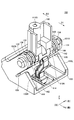
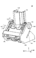
- FIGS. 1 to 3 are external perspective views of an operating device 100 according to an embodiment.
- the Z-axis direction in the drawing is the vertical direction
- the X-axis direction in the drawing is the front-back direction
- the Y-axis direction in the drawing is the left-right direction.
- An operation device 100 shown in FIGS. 1 to 3 is an operation device installed near a driver's seat in a vehicle such as an automobile, and electrically controls a shift change of a transmission mounted on the vehicle. It is an operating device for.
- the operation device 100 does not mechanically control the transmission, but employs a so-called shift-by-wire method in which a transmission is electrically controlled by outputting a control signal according to a shift operation to the outside.
- the operation device 100 may be used for purposes other than shift change of the transmission, and may be used for devices other than vehicles (for example, aircraft, railway vehicles, game machines, remote controllers, etc.).
- the operating device 100 actually has an electrical configuration for outputting an electrical signal according to a shift operation, but in the present embodiment, illustration and description of this electrical configuration will be given. It will be omitted.
- the operating device 100 has a lever portion 110 extending upward, and is associated with a tilting operation of an operating lever (not shown) attached to the lever portion 110.
- the lever portion 110 is rotatable in the front-rear direction (X-axis direction in the figure). Specifically, the lever portion 110 is provided in each of a first rotation direction D1 that is the front (the X axis positive direction in the drawing) and a second rotation direction D2 that is the rear (the X axis negative direction in the drawing). On the other hand, it is rotatable.
- the operating device 100 is relatively small as a whole and has a simple structure, but the operating lever 100 is operated regardless of whether the forward tilting operation or the backward tilting operation is performed.
- An operation feeling (a so-called click feeling) can be given to the tilting operation.
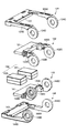
- FIG. 4 is an exploded perspective view of the operating device 100 according to the embodiment.
- FIG. 5 shows configurations of the upper yoke portion 120 (an example of a “magnetic material holding portion”), the lower yoke portion 140 (another example of a “magnetic material holding portion”), and the magnetism generating portion 150 according to the embodiment. It is an exploded perspective view.
- the operating device 100 includes a lever portion 110, an upper yoke portion 120, a holder 130 (an example of a “shaft portion holding member”), a lower yoke portion 140, and a magnetic field generator 150. Is configured.
- the magnetism generator 150 is held by the first magnet holder 133 and the second magnet holder 134 of the holder 130, and is therefore not shown in FIG.
- the lever portion 110 is a portion that rotates in the front-rear direction when the operation lever (not shown) is tilted in the front-rear direction (X-axis direction in the drawing).
- the lever portion 110 has a rotation center shaft portion 110A, and a round rod-shaped shaft 137 penetrates the through hole 110B formed in the rotation center shaft portion 110A in the left-right direction (Y-axis direction in the drawing). Is rotatably supported in the front-back direction.
- the lever portion 110 has a mounting hole 110C at the upper end, and the lower end portion of the shaft of the operating lever is fixed to the mounting hole 110C to support the operating lever.
- the lever part 110 has a column-shaped opening/closing control part 112 extending rearward and downward from the rotation center shaft part 110A.
- the opening/closing control unit 112 is arranged so as to be inserted between the upper yoke unit 120 and the lower yoke unit 140, and opens and closes the upper yoke unit 120 and the lower yoke unit 140 as the lever unit 110 rotates.
- the opening/closing control unit 112 has a first upper pressing portion 112A in the middle portion of the upper surface. 112 A of 1st upper side pressing parts push up the 1st upper side yoke 121 of the upper side yoke part 120 upwards, when the lever part 110 rotates forward predetermined angle (theta)1.
- the opening/closing control unit 112 has a second upper pressing portion 112B at the tip portion on the upper surface.
- the second upper pressing portion 112B pushes up the second upper yoke 123 of the upper yoke portion 120 when the lever portion 110 rotates forward by a predetermined angle ⁇ 2 (where ⁇ 2> ⁇ 1).
- the opening/closing control unit 112 has a first lower pressing portion 112C in the middle portion on the lower surface.
- the first lower pressing portion 112C pushes down the first lower yoke 141 of the lower yoke portion 140 when the lever portion 110 is rotated backward by a predetermined angle ⁇ 1.
- the opening/closing control unit 112 has a second lower pressing portion 112D at the tip portion on the lower surface.
- the second lower pressing portion 112D pushes down the second lower yoke 143 of the lower yoke portion 140 when the lever portion 110 rotates backward by a predetermined angle ⁇ 2.
- the lever portion 110 has a columnar sensor holding portion 114 extending downward from the rotation center shaft portion 110A.
- the sensor holder 114 holds two magnetic sensors 115 arranged side by side in the front-rear direction at the lower end thereof.
- the two magnetic sensors 115 move forward and backward with the rotation of the lever portion 110 to magnetically detect the rotation of the lever portion 110 and send the detection signal to a controller (not shown) or the like. Output.
- the upper yoke part 120 is arranged above the permanent magnets 151, 152.
- the upper yoke portion 120 is rotatably supported by the holder 130.
- the upper yoke portion 120 has a first upper yoke 121, a first upper holding portion 122, a second upper yoke 123, and a second upper holding portion 124. Is configured.
- the first upper yoke 121 and the second upper yoke 123 are examples of “magnetic material”.
- the first upper yoke 121 and the second upper yoke 123 are both flat plate members made of a magnetic material (for example, iron).
- Each of the first upper yoke 121 and the second upper yoke 123 has a planar shape that is a horizontally long rectangular shape in a plan view from above.
- the first upper yoke 121 and the second upper yoke 123 are arranged side by side in the front-rear direction (X-axis direction in the drawing) with the first upper yoke 121 on the front side.
- Both the first upper yoke 121 and the second upper yoke 123 are arranged at positions facing the upper surface of each of the permanent magnets 151 and 152.
- the first upper holding portion 122 is a member that holds the front edge of the first upper yoke 121 and is rotatably supported by the holder 130.
- the first upper holding portion 122 has a pair of left and right arm portions 122A and 122B.
- a rotation center shaft portion 122C is provided at the tip of the arm portion 122A.
- a rotation center shaft portion 122D is provided at the tip of the arm portion 122B.
- the arm portions 122A and 122B and the rotation center shaft portions 122C and 122D are examples of the “rotation center arm portion”.
- the first upper holding portion 122 is pivotally supported by the holder 130 so as to be rotatable in the front-rear direction by the shaft 137 penetrating the rotation center shaft portions 122C and 122D in the left-right direction (Y-axis direction in the drawing). ..
- the first upper yoke 121 performs a contact/separation operation with respect to the upper surface of each of the permanent magnets 151, 152 by the rotation of the first upper holding portion 122.
- the second upper holding portion 124 is a member that holds the rear and left and right edges of the second upper yoke 123, and is rotatably supported by the holder 130.
- the second upper holding portion 124 has a pair of left and right arm portions 124A and 124B.
- a rotation center shaft portion 124C is provided at the tip of the arm portion 124A.
- a rotation center shaft portion 124D is provided at the tip of the arm portion 124B.
- the arm portions 124A and 124B and the rotation center shaft portions 124C and 124D are other examples of the "rotation center arm portion".
- the second upper holding portion 124 is rotatably supported by the holder 130 in the front-rear direction by the shaft 137 penetrating the rotation center shaft portions 124C and 124D in the left-right direction (Y-axis direction in the drawing). ..
- the second upper yoke 123 performs a contact/separation operation with respect to the upper surface of each of the permanent magnets 151 and 152 as the second upper holding unit 124 rotates.
- the lower yoke part 140 is arranged below the permanent magnets 151, 152.
- the lower yoke portion 140 is rotatably supported by the holder 130.
- the lower yoke portion 140 includes a first lower yoke 141, a first lower holding portion 142, a second lower yoke 143, and a second lower holding portion. It is configured to have a portion 144.
- the first lower yoke 141 and the second lower yoke 143 are other examples of “magnetic material”.
- the first lower yoke 141 and the second lower yoke 143 are both flat plate members made of a magnetic material (for example, iron).
- Each of the first lower yoke 141 and the second lower yoke 143 has a planar shape that is a horizontally long rectangular shape in a plan view from above.
- the first lower yoke 141 and the second lower yoke 143 are arranged side by side in the front-rear direction (X-axis direction in the drawing) with the first lower yoke 141 on the front side.
- Both the first upper yoke 121 and the second upper yoke 123 are arranged at positions facing the lower surface of each of the permanent magnets 151 and 152.
- the first lower holding portion 142 is a member that holds the front edge of the first lower yoke 141 and that is pivotally supported by the holder 130.
- the first lower holding portion 142 has a pair of left and right arm portions 142A and 142B.
- a rotation center shaft portion 142C is provided at the tip of the arm portion 142A.
- the arm portions 142A and 142B and the rotation center shaft portions 142C and 142D are other examples of the "rotation center arm portion”.
- a rotation center shaft portion 142D is provided at the tip of the arm portion 142B.
- the first lower holding portion 142 is rotatably supported in the front-rear direction by the holder 130 by the shaft 137 penetrating the rotation center shaft portions 142C and 142D in the left-right direction (Y-axis direction in the drawing). It The first lower yoke 141 performs a contact/separation operation with respect to the lower surface of each of the permanent magnets 151 and 152 as the first lower holding portion 142 rotates.
- the second lower holding portion 144 is a member that holds the rear and left and right edges of the second lower yoke 143, and is pivotally supported by the holder 130.
- the second lower holding portion 144 has a pair of left and right arm portions 144A and 124B.
- a rotation center shaft portion 144C is provided at the tip of the arm portion 144A.
- a rotation center shaft portion 144D is provided at the tip of the arm portion 144B.
- the arm portions 144A and 144B and the rotation center shaft portions 144C and 144D are other examples of the "rotation center arm portion".
- the second lower holding portion 144 is rotatably supported by the holder 130 in the front-rear direction by the shaft 137 penetrating the rotation center shaft portions 144C and 144D in the left-right direction (Y-axis direction in the drawing). It The second lower yoke 143 performs a contact/separation operation with respect to the lower surface of each of the permanent magnets 151 and 152 as the second lower holding portion 144 rotates.
- the holder 130 is an example of a “holding member”.
- the holder 130 has a first arm portion 131, a second arm portion 132, a first magnet holding portion 133, a second magnet holding portion 134, a connecting portion 138, and a shaft 137.
- the holder 130 is formed using a non-magnetic material (for example, resin, aluminum die cast, etc.).
- each component (the first arm portion 131, the second arm portion 132, the first magnet holding portion 133, the second magnet holding portion 134, and the connecting portion 138) is integrally formed by injection molding or the like. Has been formed.
- the first arm portion 131 and the second arm portion 132 are an example of “a pair of support portions”.
- the holder 130 pivotally supports the rotation center shaft portion 110A of the lever portion 110 by the first arm portion 131, the second arm portion 132, and the shaft 137.
- the first arm portion 131 is an example of “one support portion”, and extends on the left side (Y-axis positive side in the drawing) of the holder 130 toward the front and upward toward the rotation center shaft portion 110A of the lever portion 110. It is an existing flat plate-shaped portion. A bearing portion 131 ⁇ /b>A that supports one end of the shaft 137 is provided at the tip of the first arm portion 131.
- the second arm portion 132 is an example of “the other support portion”, and on the right side (Y-axis negative side in the drawing) of the holder 130, toward the rotation center shaft portion 110A of the lever portion 110, forward and upward. It is a flat plate-shaped portion that extends. A bearing portion 132 ⁇ /b>A that supports the other end of the shaft 137 is provided at the tip portion of the second arm portion 132.
- the rotation center shaft part 110A of the lever part 110 is arranged in the center between the bearing part 131A of the first arm part 131 and the bearing part 132A of the second arm part 132. Then, the shaft 137 penetrates through the through hole 110B provided in the rotation center shaft portion 110A of the lever portion 110 in the left-right direction (Y-axis direction in the drawing). One end of the shaft 137 is supported by the bearing portion 131A. The other end of the shaft 137 is supported by the bearing portion 132A. As a result, the rotation center shaft portion 110A of the lever portion 110 is pivotally supported by the holder 130 so as to be rotatable in the front-rear direction (X-axis direction in the drawing).
- the first magnet holder 133 and the second magnet holder 134 hold the permanent magnets 151 and 152. Specifically, the first magnet holding portion 133 and the second magnet holding portion 134 are provided between the upper yoke portion 120 and the lower yoke portion 140, and the first arm portion 131 and the second arm portion 132. It is provided between.
- the first magnet holding portion 133 has a hollow structure and holds the permanent magnet 151 in the internal space.
- the second magnet holding portion 134 has a hollow structure and holds the permanent magnet 152 in the internal space.
- the holder 130 includes a first upper holding portion 122 and a second upper holding portion 124 of the upper yoke portion 120, a first lower holding portion 142 and a second lower side of the lower yoke portion 140.
- the holding portion 144 (hereinafter collectively referred to as "four holding portions 122, 124, 142, 144") is rotatably supported.
- one arm portion of each of the four holding portions 122, 124, 142, 144 (see FIG. A tip portion (rotation center shaft portion) of the middle Y-axis positive side arm portion is arranged in the Y-axis direction in an overlapping manner, and is pivotally supported by a shaft 137 penetrating them.
- each of the four holding portions 122, 124, 142, and 144 (Y-axis in the drawings).
- the distal end portion (rotation center shaft portion) of the negative arm portion) is arranged so as to overlap in the Y-axis direction, and is pivotally supported by a shaft 137 penetrating them.
- the holder 130 pivotally supports each of the four holding portions 122, 124, 142, 144 together with the rotation center shaft portion 110A.
- the magnetic field generator 150 has a permanent magnet 151 and a permanent magnet 152 having different magnetic poles in the vertical direction.
- the permanent magnets 151 and 152 are arranged so that different magnetic poles face each other between the first upper yoke 121 and the second upper yoke 123 and the first lower yoke 141 and the second lower yoke 143.
- the magnets are held by the first magnet holding portion 133 and the second magnet holding portion 134 of the holder 130 while being arranged side by side in the left-right direction.
- the permanent magnet 152 is held so that the upper surface side is the N pole and the lower surface side is the S pole.
- the upper surfaces of the permanent magnets 151, 152 face the lower surfaces of the first upper yoke 121 and the second upper yoke 123, respectively. As a result, the permanent magnets 151 and 152 can magnetize the first upper yoke 121 and the second upper yoke 123, respectively.
- the lower surfaces of the permanent magnets 151, 152 face the upper surfaces of the first lower yoke 141 and the second lower yoke 143, respectively. As a result, the permanent magnets 151, 152 can magnetize the first lower yoke 141 and the second lower yoke 143, respectively.
- Each of the permanent magnets 151 and 152 has a rectangular parallelepiped shape whose longitudinal direction is the front-back direction (X-axis direction in the figure), and has different magnetic poles in the vertical direction.
- the permanent magnets 151 and 152 for example, a neodymium magnet, a ferrite magnet, a samarium cobalt magnet, an alnico magnet, or the like can be used.
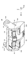
- FIG. 6 is an external perspective view of the holder 130 according to the embodiment as viewed from the rear and from below. As shown in FIG. 6, the holder 130 has a first magnet holding portion 133 and a second magnet holding portion 134. The first magnet holding portion 133 and the second magnet holding portion 134 are arranged side by side in the left-right direction (Y-axis direction in the drawing) between the first arm portion 131 and the second arm portion 132.
- the first magnet holding portion 133 is provided on the first arm portion 131 side (Y axis positive side in the drawing).
- the first magnet holding portion 133 has a hollow structure having an opening on the rear side (the X-axis negative side in the drawing), and the permanent magnet 151 is arranged in the internal space.
- the second magnet holding portion 134 is provided on the second arm portion 132 side (Y axis negative side in the drawing).
- the second magnet holding portion 134 has a hollow structure having an opening on the rear side (X axis negative side in the drawing), and the permanent magnet 152 is arranged in the internal space.
- the permanent magnet 151 and the permanent magnet 152 are arranged so that the magnetic poles are opposite in the vertical direction.
- the permanent magnets 151 and 152 are held by the holder 130 in a state where the permanent magnets 151 and 152 are arranged side by side in the left-right direction and the N pole and the S pole which are different magnetic poles face each other.
- the first magnet holding portion 133 and the second magnet holding portion 134 are connected to each other by the connecting portion 138 provided between them.
- the connecting portion 138 is formed in a shape having a relatively low strength (in the example shown in FIG. 6, a thin shape). Accordingly, the connecting portion 138 is appropriately elastically deformed so that the first magnet holding portion 133 and the second magnet holding portion 134 can be moved toward each other due to the mutual magnetic attraction of the permanent magnets 151 and 152. It is possible.
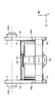
- FIG. 7 is a diagram for explaining the action of the mutual magnetic attraction force of the two permanent magnets 151 and 152 generated in the holder 130 according to the embodiment.
- the first magnet holding portion 133 holding the permanent magnet 151 and the second magnet holding portion 134 holding the permanent magnet 152 are formed by the magnetic attraction force generated between the permanent magnets 151 and 152.
- a force is applied in the direction toward each other.
- the first magnet holding portion 133 and the second magnet holding portion 134 can be brought close to each other by the connecting portion 138 being elastically deformed by receiving the force in the direction toward each other. Accordingly, the first arm portion 131 integrally formed with the first magnet holding portion 133 and the second arm portion 132 integrally formed with the second magnet holding portion 134 are mutually Move toward you. As a result, the distance between the first arm portion 131 and the second arm portion 132 is narrowed.
- the rotation center shaft portion of the lever portion 110 is provided between the first arm portion 131 and the second arm portion 132, together with the four holding portions 122, 124, 142 and 144.
- 110A is sandwiched. Therefore, the distance between the first arm portion 131 and the second arm portion 132 is narrowed, so that the rotation center shaft portion 110A and the arm portions 122A, 122B of the four holding portions 122, 124, 142, 144, respectively.
- 124A, 124B, 142A, 142B, 144A, 144B and the rotation center shaft portions 122C, 122D, 124C, 124D, 142C, 142D, 144C, 144D are sandwiched in a state that they are in contact with each other, and slide in contact with each other.
- the frictional resistance in the rotational direction of the surface is increased, and thus the load of the lever portion 110 and each of the four holding portions 122, 124, 142, 144 in the rotational movement is increased.
- a slit 135 is formed on the left side wall portion 130L of the holder 130 (the Y-axis positive side in the drawings) (an example of “one side wall portion”). ..
- a slit 136 is formed on a side wall portion 130R (an example of “side wall portion on the other side”) on the right side (Y-axis negative side in the drawing) of the holder 130.
- the slit 135 is a part that is cut out rearward and downward from the tip side of the first arm 131 along the extending direction of the first arm 131.
- the slit 135 forms the lower edge of the first arm 131, that is, defines the elastically deformable length of the first arm 131. Therefore, by adjusting the length of the slit 135, it is possible to adjust the ease of elastic deformation of the first arm 131 in the left-right direction (Y-axis direction in the drawing).
- the slit 136 is a portion cut out rearward and downward from the distal end side of the second arm portion 132 along the extending direction of the second arm portion 132.
- the slit 136 forms the lower edge of the second arm 132, that is, defines the elastically deformable length of the second arm 132. Therefore, by adjusting the length of the slit 136, it is possible to adjust the ease of elastic deformation of the second arm portion 132 in the left-right direction (Y-axis direction in the drawing).
- the slits 135 and 136 are made relatively long so that the elasticity of each of the first arm portion 131 and the second arm portion 132 is increased.
- the magnetic force from the permanent magnets 151, 152 makes it easier for the gap between the first arm portion 131 and the second arm portion 132 to become narrower. Is possible.
- FIGS. 8 to 10 are diagrams for explaining the operation when the forward tilting operation is performed in the operating device 100 according to the embodiment.
- the first upper yoke 121 and the second upper yoke 123 are affected by the magnetic attraction force from the permanent magnets 151 and 152.
- the upper surfaces of the permanent magnets 151 and 152 are magnetically attached. That is, the first upper holding portion 122 and the second upper holding portion 124 are in a closed state.
- the first lower yoke 141 and the second lower yoke 143 are magnetically attached to the lower surfaces of the permanent magnets 151 and 152 by the magnetic attraction force from the permanent magnets 151 and 152. ing.
- the lever portion 110 is in a state where the neutral state is stably maintained. That is, the first lower holding portion 142 and the second lower holding portion 144 are in a closed state.
- the lever portion 110 rotates about the shaft 137 as the rotation axis in the first rotation direction D1 until the rotation angle becomes the predetermined angle ⁇ 1. At this time, the resistance force of the lever portion 110 is rapidly reduced, that is, the operation of the lever portion 110 is abruptly lightened, so that the operator may feel a click feeling in the first step due to the change in the load. it can.
- the lever portion 110 rotates about the shaft 137 as the rotation axis in the first rotation direction D1 until the rotation angle reaches the predetermined angle ⁇ 2. At this time, since the resistance force in the lever portion 110 is rapidly reduced, that is, the operation of the lever portion 110 is suddenly lightened, the operator may feel a click feeling in the second stage due to this load change. it can.
- the magnetic force from the permanent magnets 151 and 152 causes the first upper yoke.
- the 121 and the second upper yoke 123 are magnetically attached to the upper surfaces of the permanent magnets 151 and 152.
- the lever portion 110 rotates about the shaft 137 as the rotation axis in the second rotation direction D2, whereby the inclination in the first rotation direction D1 is eliminated, and the neutral position is automatically neutralized. It returns to the state (see FIG. 8).
- the operating device 100 of this embodiment has the upper and lower yoke portions 120 and 140 having a vertically symmetrical structure with the permanent magnets 151 and 152 interposed therebetween. Therefore, in the operating device 100 of the present embodiment, even when the tilting operation to the rear (the second rotation direction D2) is performed, it is the same as when the tilting operation to the front (the first rotation direction D1) is performed. In addition, it is possible to give a two-step click feeling to the backward tilting operation.
- the lever portion 110 when the tilting operation is performed by the lever portion 110 to the rear (the second rotation direction D2) at the predetermined angle ⁇ 1, the lever portion 110 is moved to the first lower pressing portion 112C (see FIG. 4) by the first lower pressing portion 112C.
- the lower yoke 141 of No. 1 is pushed down.
- the magnetic force of the permanent magnets 151 and 152 to the first lower yoke 141 causes a resistance force against the tilting operation in the lever portion 110.
- the first lower yoke 141 pulls downward with respect to the lower surfaces of the permanent magnets 151 and 152. It is peeled off.
- the lever portion 110 rotates about the shaft 137 in the second rotation direction D2 until the rotation angle reaches the predetermined angle ⁇ 1.
- the resistance force of the lever portion 110 is rapidly reduced, that is, the operation of the lever portion 110 is abruptly lightened, so that the operator may feel a click feeling in the first step due to the change in the load. it can.
- the lever portion 110 when the tilting operation is performed by the lever portion 110 toward the rear (second rotation direction D2) at the predetermined angle ⁇ 2, the lever portion 110 is moved by the second lower pressing portion 112D (see FIG. 4) to The lower yoke 143 of 2 is pushed down. At this time, the magnetic force of the permanent magnets 151 and 152 to the second lower yoke 143 causes a resistance force to the tilting operation in the lever portion 110. Then, when the operator applies a backward biasing force that overcomes this resistance force to the lever portion 110, the second lower yoke 143 pulls downward with respect to the lower surfaces of the permanent magnets 151 and 152. It is peeled off.
- the lever portion 110 rotates about the shaft 137 as the rotation axis in the second rotation direction D2 until the rotation angle reaches the predetermined angle ⁇ 2.
- the resistance force in the lever portion 110 is rapidly reduced, that is, the operation of the lever portion 110 is suddenly lightened, the operator may feel a click feeling in the second stage due to this load change. it can.
- the magnetic force from the permanent magnets 151 and 152 causes the first lower side.
- the yoke 141 and the second lower yoke 143 are magnetically attached to the lower surfaces of the permanent magnets 151 and 152.
- the lever portion 110 rotates about the shaft 137 as the rotation axis in the first rotation direction D1, thereby eliminating the inclination in the second rotation direction D2 and automatically neutralizing. It returns to the state (see FIG. 8).
- the operating device 100 of the present embodiment has the rotation center shaft portion on both outer sides of the lever portion 110 that rotates with the tilting operation of the operation lever and the rotation center shaft portion 110A of the lever portion 110.
- a holder 130 holding member having a first arm portion 131 and a second arm portion 132 (a pair of support portions) that rotatably sandwich the 110A, and the holder 130 holds the holder 130 on the first arm portion 131 side.
- Generating unit 150 having a permanent magnet 151 (first magnet) that has been generated and a permanent magnet 152 (second magnet) that is held on the second arm 132 side in the holder 130, and a magnetic generating unit 150.
- the magnets 150 are arranged facing each other and move toward and away from the magnetism generating part 150 as the lever part 110 rotates. At the time of the contacting and separating action, the magnetic force from the magnetism generating part 150 causes tilting operation.
- the holder 130 is provided with a first upper yoke 121, a second upper yoke 123, a first lower yoke 141, and a second lower yoke 143 (magnetic body) that give a feeling of operation.
- the magnetic force generated between 151 and the permanent magnet 152 narrows the distance between the first arm 131 and the second arm 132.
- the operating device 100 of the present embodiment can increase the sliding resistance in the rotation center shaft portion 110A and increase the load in the rotation operation of the lever portion 110. Therefore, according to the operating device 100 of the present embodiment, it is possible to suppress the impact sound when the tilting operation of the operating member is released, with a relatively simple configuration.
- the holder 130 holds the first magnet holding portion 133 that holds the permanent magnet 151 on the first arm 131 side and the permanent magnet 152 on the second arm 132 side.
- the second magnet holding part 134 and the connecting part 138 connecting the first magnet holding part 133 and the second magnet holding part 134, and the permanent magnet 151 and the permanent magnet 152 are connected by a magnetic attraction force.
- the elastic deformation of the portion 138 narrows the interval between the first arm portion 131 and the second arm portion 132.
- the operating device 100 of the present embodiment it is not necessary to separately provide a member that adjusts the load in the rotation operation of the lever portion 110, and the coupling is performed according to the magnetic attraction force between the permanent magnet 151 and the permanent magnet 152.
- the shape and the like of the portion 138 and adjusting the easiness of elastic deformation of the connecting portion 138 it is possible to adjust the load of the pivotal movement of the lever portion 110. Therefore, according to the operating device 100 of the present embodiment, it is possible to adjust the load in the rotation operation of the lever portion 110 with a relatively simple configuration.
- the holder 130 is integrally formed with the first magnet holding portion 133, the second magnet holding portion 134, and the connecting portion 138.
- the operating device 100 of the present embodiment can relatively easily form the connecting portion 138 capable of adjusting the load in the rotating operation of the lever portion 110.
- each of the first arm portion 131 and the second arm portion 132 is elastically deformed in a direction in which the interval between the first arm portion 131 and the second arm portion 132 is narrowed. It is possible.
- the magnetic force between the permanent magnet 151 and the permanent magnet 152 makes it easier to narrow the gap between the first arm 131 and the second arm 132. it can. Therefore, according to the operating device 100 of the present embodiment, it is possible to easily increase the load in the rotation operation of the lever portion 110.
- the first arm portion 131 has the slit 135 formed along the extending direction of the first arm portion 131 on the side wall portion 130L on one side of the holder 130.
- the elastically deformable length of the first arm portion 131 is defined, and the second arm portion 132 is provided on the other side wall portion 130R of the holder 130 in the extending direction of the second arm portion 132.
- the slit 136 formed along the length defines the elastically deformable length of the second arm portion 132.
- the easiness of elastic deformation of the first arm 131 and the second arm 132 can be easily adjusted by the slits 135 and 136. Therefore, according to the operating device 100 of the present embodiment, it is possible to easily adjust the load in the rotation operation of the lever portion 110.
- the holder 130 has the first arm portion 131 and the second arm portion 132, and the first arm portion 131 and the second arm portion 132 are elastically deformed.
- the distance between the pair of support portions is narrowed, but the invention is not limited to this.
- the holder 130 may not have the first arm portion 131 and the second arm portion 132, and the holder 130 itself may be elastically deformed to reduce the distance between the pair of support portions.
- the connecting portion 138 that connects the first magnet holding portion 133 and the second magnet holding portion 134 is provided, and the connecting portion 138 elastically deforms the first magnet holding portion 133.
- the gap between the magnet holding portion 133 and the second magnet holding portion 134 is narrowed to narrow the gap between the pair of support portions, the present invention is not limited to this.
- the first magnet holding portion 133 and the second magnet holding portion are retained by the mutual magnetic attraction of the permanent magnets 151 and 152.
- the distance between the pair of support portions may be narrowed by narrowing the distance between the portion 134 and the portion 134.
Landscapes
- Engineering & Computer Science (AREA)
- Chemical & Material Sciences (AREA)
- Combustion & Propulsion (AREA)
- Transportation (AREA)
- Mechanical Engineering (AREA)
- Physics & Mathematics (AREA)
- General Physics & Mathematics (AREA)
- Automation & Control Theory (AREA)
- Mechanical Control Devices (AREA)
- Arrangement Or Mounting Of Control Devices For Change-Speed Gearing (AREA)
Abstract
操作装置は、操作レバーの傾倒操作に伴って回動するレバー部と、レバー部が有する回転中心軸部の両外側において、回転中心軸部を回動可能に挟持する一対の支持部を有する軸部保持部材と、軸部保持部材において、一対の支持部のうちの一方の支持部の側に保持された第1の磁石と、軸部保持部材において、一対の支持部のうちの他方の支持部の側に保持された第2の磁石とを有する磁気発生部と、磁気発生部と対向して配置され、レバー部の回動に伴って磁気発生部に対して接離動作し、磁気発生部からの磁着力によって傾倒操作に対して操作感を付与する磁性体とを備え、軸部保持部材は、第1の磁石と第2の磁石との間に生じる磁着力によって、一対の支持部の間隔が狭められる。
Description
本発明は、操作装置に関する。
従来、例えば、自動車等の車両に搭載される操作装置として、操作レバーによる傾倒操作によって、変速機のシフトチェンジを電気的に制御することが可能な操作装置が知られている。
このような操作装置に関し、操作レバーによる傾倒操作に操作感(いわゆるクリック感)を発生させることにより、当該傾倒操作が確実に行われたことを、操作者が触覚的に把握できるようにした技術が考案されている。
例えば、下記特許文献1には、車両用のシフト装置に関し、可動部材に設けられた可動側磁性体と、可動側磁性体と対向して配置された対向側磁性体とを備え、操作部材が傾倒操作された際に、操作部材とともに回動する基体部によって、可動部材を押し上げることにより、対向側磁性体と可動側磁性体との間の吸引力に反して、対向側磁性体から可動側磁性体を離間させることにより、傾倒操作に節度感を与える技術が開示されている。
しかしながら、上記特許文献1の技術では、ユーザによる操作部材の傾倒操作が解除された際に、互いに対向する磁性体同士の吸引力によって、操作部材が急激に元の位置に復帰し、その際に、互いに対向する磁性体同士が当接して、打撃音が生じる等の不具合が生じる虞がある。そこで、本発明の発明者は、比較的簡単な構成により、操作部材の傾倒操作が解除された際の不具合を抑制することが可能な、操作装置の必要性を見出した。
一実施形態の操作装置は、操作レバーの傾倒操作に伴って回動するレバー部と、レバー部が有する回転中心軸部の両外側において、回転中心軸部を回動可能に挟持する一対の支持部を有する軸部保持部材と、軸部保持部材において、一対の支持部のうちの一方の支持部の側に保持された第1の磁石と、軸部保持部材において、一対の支持部のうちの他方の支持部の側に保持された第2の磁石とを有する磁気発生部と、磁気発生部と対向して配置され、レバー部の回動に伴って磁気発生部に対して接離動作し、磁気発生部からの磁着力によって傾倒操作に対して操作感を付与する磁性体とを備え、軸部保持部材は、第1の磁石と第2の磁石との間に生じる磁着力によって、一対の支持部の間隔が狭められる。
一実施形態によれば、比較的簡単な構成により、操作部材の傾倒操作が解除された際の不具合を抑制することが可能な、操作装置を実現することができる。
以下、図面を参照して、一実施形態について説明する。
(操作装置100の概要)
図1~図3は、一実施形態に係る操作装置100の外観斜視図である。なお、以降の説明では、便宜上、図中Z軸方向を、上下方向とし、図中X軸方向を、前後方向とし、図中Y軸方向を、左右方向とする。
図1~図3は、一実施形態に係る操作装置100の外観斜視図である。なお、以降の説明では、便宜上、図中Z軸方向を、上下方向とし、図中X軸方向を、前後方向とし、図中Y軸方向を、左右方向とする。
図1~図3に示す操作装置100は、自動車等の車両の車内において、運転席の近傍に設置される操作装置であって、車両に搭載された変速機のシフトチェンジを電気的に制御するための操作装置である。操作装置100は、変速機を機械的に制御するものではなく、シフト操作に応じた制御信号を外部に出力することによって変速機を電気的に制御する、いわゆるシフトバイワイヤ方式を採用している。
なお、操作装置100は、変速機のシフトチェンジ以外の目的に用いられてよく、車両以外の機器(例えば、航空機、鉄道車両、ゲーム機、リモコン等)に用いられてもよい。また、操作装置100は、実際には、シフト操作に応じた電気信号を出力するための電気的な構成を有しているが、本実施形態では、この電気的な構成についての図示および説明を省略することとする。
図1~図3に示すように、操作装置100は、上方に向って延在するレバー部110を有しており、当該レバー部110に取り付けられる操作レバー(図示省略)の傾倒操作に伴って、レバー部110が前後方向(図中X軸方向)に回動可能である。具体的には、レバー部110は、前方(図中X軸正方向)である第1回動方向D1、および、後方(図中X軸負方向)である第2回動方向D2のそれぞれに対して、回動可能である。
特に、操作装置100は、全体的に比較的小型であり、且つ、簡素な構成でありながら、前方への傾倒操作および後方への傾倒操作のいずれが行われた場合であっても、操作レバーの傾倒操作に対して、操作感(いわゆるクリック感)を与えることができるようになっている。
(操作装置100の構成)
図4は、一実施形態に係る操作装置100の分解斜視図である。図5は、一実施形態に係る上側ヨーク部120(「磁性体保持部」一例)、下側ヨーク部140(「磁性体保持部」の他の一例)、および磁気発生部150の構成を示す分解斜視図である。
図4は、一実施形態に係る操作装置100の分解斜視図である。図5は、一実施形態に係る上側ヨーク部120(「磁性体保持部」一例)、下側ヨーク部140(「磁性体保持部」の他の一例)、および磁気発生部150の構成を示す分解斜視図である。
図4および図5に示すように、操作装置100は、レバー部110、上側ヨーク部120、ホルダ130(「軸部保持部材」の一例)、下側ヨーク部140、および磁気発生部150を備えて構成されている。なお、磁気発生部150は、ホルダ130の第1磁石保持部133、第2磁石保持部134によって保持されているため、図4には示されていない。
レバー部110は、操作レバー(図示省略)の前後方向(図中X軸方向)への傾倒操作に伴って、前後方向に回動する部分である。レバー部110は、回転中心軸部110Aを有しており、当該回転中心軸部110Aに形成された貫通孔110Bを、丸棒状のシャフト137が左右方向(図中Y軸方向)に貫通することによって、前後方向に回動可能に軸支される。なお、レバー部110は、上端部に取付孔110Cを有し、当該取付孔110Cに対して操作レバーが有するシャフトの下端部が固定されることにより、操作レバーを支持する。
レバー部110は、回転中心軸部110Aから後方且つ下方に向って延在する柱状の開閉制御部112を有している。開閉制御部112は、上側ヨーク部120と下側ヨーク部140との間に入り込んで配置され、レバー部110の回動に伴って、上側ヨーク部120および下側ヨーク部140を開閉させる。
具体的には、開閉制御部112は、上面における中間部分に、第1上側押圧部112Aを有する。第1上側押圧部112Aは、レバー部110が前方に所定角度θ1回動したときに、上側ヨーク部120の第1の上側ヨーク121を上方に押し上げる。
また、開閉制御部112は、上面における先端部分に、第2上側押圧部112Bを有する。第2上側押圧部112Bは、レバー部110が前方に所定角度θ2(但し、θ2>θ1)回動したときに、上側ヨーク部120の第2の上側ヨーク123を上方に押し上げる。
また、開閉制御部112は、下面における中間部分に、第1下側押圧部112Cを有する。第1下側押圧部112Cは、レバー部110が後方に所定角度θ1回動したときに、下側ヨーク部140の第1の下側ヨーク141を下方に押し下げる。
また、開閉制御部112は、下面における先端部分に、第2下側押圧部112Dを有する。第2下側押圧部112Dは、レバー部110が後方に所定角度θ2回動したときに、下側ヨーク部140の第2の下側ヨーク143を下方に押し下げる。
また、レバー部110は、回転中心軸部110Aから下方に向って延在する柱状のセンサ保持部114を有している。センサ保持部114は、その下端部において、前後方向に並べて配置された2つの磁気センサ115を保持する。2つの磁気センサ115は、レバー部110の回動に伴って前後方向に移動することにより、レバー部110の回動を磁気的に検出して、その検出信号を、図示を省略するコントローラ等に出力する。
上側ヨーク部120は、永久磁石151,152よりも上側に配置される。上側ヨーク部120は、ホルダ130によって回動可能に軸支される。具体的には、上側ヨーク部120は、図5に示すように、第1の上側ヨーク121、第1の上側保持部122、第2の上側ヨーク123、および第2の上側保持部124を有して構成されている。
第1の上側ヨーク121および第2の上側ヨーク123は、「磁性体」の一例である。第1の上側ヨーク121および第2の上側ヨーク123は、いずれも磁性材料(例えば、鉄)からなる平板状の部材である。第1の上側ヨーク121および第2の上側ヨーク123は、上方からの平面視において、いずれも横長の長方形状をなす平面形状を有している。第1の上側ヨーク121および第2の上側ヨーク123は、第1の上側ヨーク121が前側となって、前後方向(図中X軸方向)に並べて配置されている。第1の上側ヨーク121および第2の上側ヨーク123は、いずれも永久磁石151,152の各々の上面と対向する位置に配置される。
第1の上側保持部122は、第1の上側ヨーク121の前側の縁部を把持し、且つ、ホルダ130によって回動可能に軸支される部材である。第1の上側保持部122は、左右一対の腕部122A,122Bを有する。腕部122Aの先端には、回転中心軸部122Cが設けられている。腕部122Bの先端には、回転中心軸部122Dが設けられている。腕部122A,122B及び回転中心軸部122C,122Dは、「回転中心腕部」の一例である。第1の上側保持部122は、回転中心軸部122C,122Dを、シャフト137が左右方向(図中Y軸方向)に貫通することにより、ホルダ130によって前後方向に回動可能に軸支される。第1の上側ヨーク121は、第1の上側保持部122が回動することにより、永久磁石151,152の各々の上面に対する接離動作を行う。
第2の上側保持部124は、第2の上側ヨーク123の後側および左右両側の縁部を把持し、且つ、ホルダ130によって回動可能に軸支される部材である。第2の上側保持部124は、左右一対の腕部124A,124Bを有する。腕部124Aの先端には、回転中心軸部124Cが設けられている。腕部124Bの先端には、回転中心軸部124Dが設けられている。腕部124A,124B及び回転中心軸部124C,124Dは、「回転中心腕部」の他の一例である。第2の上側保持部124は、回転中心軸部124C,124Dを、シャフト137が左右方向(図中Y軸方向)に貫通することにより、ホルダ130によって前後方向に回動可能に軸支される。第2の上側ヨーク123は、第2の上側保持部124が回動することにより、永久磁石151,152の各々の上面に対する接離動作を行う。
下側ヨーク部140は、永久磁石151,152よりも下側に配置される。下側ヨーク部140は、ホルダ130によって回動可能に軸支される。具体的には、下側ヨーク部140は、図5に示すように、第1の下側ヨーク141、第1の下側保持部142、第2の下側ヨーク143、第2の下側保持部144を有して構成されている。
第1の下側ヨーク141および第2の下側ヨーク143は、「磁性体」の他の一例である。第1の下側ヨーク141および第2の下側ヨーク143は、いずれも磁性材料(例えば、鉄)からなる平板状の部材である。第1の下側ヨーク141および第2の下側ヨーク143は、上方からの平面視において、いずれも横長の長方形状をなす平面形状を有している。第1の下側ヨーク141および第2の下側ヨーク143は、第1の下側ヨーク141が前側となって、前後方向(図中X軸方向)に並べて配置されている。第1の上側ヨーク121および第2の上側ヨーク123は、いずれも永久磁石151,152の各々の下面と対向する位置に配置される。
第1の下側保持部142は、第1の下側ヨーク141の前側の縁部を把持し、且つ、ホルダ130によって回動可能に軸支される部材である。第1の下側保持部142は、左右一対の腕部142A,142Bを有する。腕部142Aの先端には、回転中心軸部142Cが設けられている。腕部142A,142B及び回転中心軸部142C,142Dは、「回転中心腕部」の他の一例である。腕部142Bの先端には、回転中心軸部142Dが設けられている。第1の下側保持部142は、回転中心軸部142C,142Dを、シャフト137が左右方向(図中Y軸方向)に貫通することにより、ホルダ130によって前後方向に回動可能に軸支される。第1の下側ヨーク141は、第1の下側保持部142が回動することにより、永久磁石151,152の各々の下面に対する接離動作を行う。
第2の下側保持部144は、第2の下側ヨーク143の後側および左右両側の縁部を把持し、且つ、ホルダ130によって回動可能に軸支される部材である。第2の下側保持部144は、左右一対の腕部144A,124Bを有する。腕部144Aの先端には、回転中心軸部144Cが設けられている。腕部144Bの先端には、回転中心軸部144Dが設けられている。腕部144A,144B及び回転中心軸部144C,144Dは、「回転中心腕部」の他の一例である。第2の下側保持部144は、回転中心軸部144C,144Dを、シャフト137が左右方向(図中Y軸方向)に貫通することにより、ホルダ130によって前後方向に回動可能に軸支される。第2の下側ヨーク143は、第2の下側保持部144が回動することにより、永久磁石151,152の各々の下面に対する接離動作を行う。
ホルダ130は、「保持部材」の一例である。ホルダ130は、第1の腕部131、第2の腕部132、第1磁石保持部133、第2磁石保持部134、連結部138、およびシャフト137を有する。例えば、ホルダ130は、非磁性材料(例えば、樹脂、アルミダイキャスト等)が用いられて形成される。ホルダ130は、各構成部(第1の腕部131、第2の腕部132、第1磁石保持部133、第2磁石保持部134、および連結部138)が射出成形等により、一体的に形成されている。
第1の腕部131および第2の腕部132は、「一対の支持部」の一例である。ホルダ130は、第1の腕部131、第2の腕部132、およびシャフト137により、レバー部110の回転中心軸部110Aを回動可能に軸支する。
第1の腕部131は、「一方の支持部」の一例であり、ホルダ130の左側(図中Y軸正側)において、レバー部110の回転中心軸部110Aに向って前方且つ上方に延在する平板状の部分である。第1の腕部131の先端部には、シャフト137の一端を支持する軸受部131Aが設けられている。
第2の腕部132は、「他方の支持部」の一例であり、ホルダ130の右側(図中Y軸負側)において、レバー部110の回転中心軸部110Aに向って、前方且つ上方に延在する平板状の部分である。第2の腕部132の先端部には、シャフト137の他端を支持する軸受部132Aが設けられている。
第1の腕部131の軸受部131Aと、第2の腕部132の軸受部132Aとの間においては、レバー部110の回転中心軸部110Aが中央に配置される。そして、レバー部110の回転中心軸部110Aに設けられた貫通孔110Bを、シャフト137が左右方向(図中Y軸方向)に貫通する。シャフト137の一端は、軸受部131Aによって支持される。シャフト137の他端は、軸受部132Aによって支持される。これにより、レバー部110の回転中心軸部110Aは、ホルダ130によって、前後方向(図中X軸方向)に回動可能に軸支される。
第1磁石保持部133および第2磁石保持部134は、永久磁石151,152を保持する。具体的には、第1磁石保持部133および第2磁石保持部134は、上側ヨーク部120と下側ヨーク部140との間、且つ、第1の腕部131と第2の腕部132との間に設けられている。第1磁石保持部133は、中空構造を有しており、内部空間において永久磁石151を保持する。第2磁石保持部134は、中空構造を有しており、内部空間において永久磁石152を保持する。
また、ホルダ130は、上側ヨーク部120が有する第1の上側保持部122および第2の上側保持部124と、下側ヨーク部140が有する第1の下側保持部142および第2の下側保持部144と(以下、まとめて「4つの保持部122,124,142,144」と示す)を、回動可能に軸支する。
具体的には、図1~図3に示すように、軸受部131Aと回転中心軸部110Aとの隙間においては、4つの保持部122,124,142,144の各々の一方の腕部(図中Y軸正側の腕部)の先端部(回転中心軸部)が、Y軸方向に重ねて配置され、これらを貫通するシャフト137によって軸支される。
また、図1~図3に示すように、軸受部132Aと回転中心軸部110Aとの隙間には、4つの保持部122,124,142,144の各々の他方の腕部(図中Y軸負側の腕部)の先端部(回転中心軸部)が、Y軸方向に重ねて配置され、これらを貫通するシャフト137によって軸支される。
これにより、ホルダ130は、回転中心軸部110Aとともに、4つの保持部122,124,142,144の各々を、回動可能に軸支する。
磁気発生部150は、図5に示すように、上下方向に異なる磁極を有する永久磁石151および永久磁石152を有する。永久磁石151,152は、第1の上側ヨーク121および第2の上側ヨーク123と、第1の下側ヨーク141および第2の下側ヨーク143との間において、互いに異なる磁極が対向するように左右方向に並べて配置された状態で、ホルダ130の第1磁石保持部133、第2磁石保持部134によって保持される。例えば、永久磁石151の上面側がS極、下面側がN極の場合は、永久磁石152の上面側がN極、下面側がS極となるように保持される。
永久磁石151,152の上面は、第1の上側ヨーク121および第2の上側ヨーク123の各々の下面と対向する。これにより、永久磁石151,152は、第1の上側ヨーク121および第2の上側ヨーク123の各々を磁着可能である。
永久磁石151,152の下面は、第1の下側ヨーク141および第2の下側ヨーク143の各々の上面と対向する。これにより、永久磁石151,152は、第1の下側ヨーク141および第2の下側ヨーク143の各々を磁着可能である。
永久磁石151,152は、いずれも前後方向(図中X軸方向)を長手方向とする直方体形状を有しており、上下方向に異なる磁極を有している。永久磁石151,152としては、例えば、ネオジム磁石、フェライト磁石、サマリウムコバルト磁石、アルニコ磁石等を用いることができる。
(ホルダ130による永久磁石151,152の保持構成)
図6は、一実施形態に係るホルダ130を後方且つ下方から見た外観斜視図である。図6に示すように、ホルダ130は、第1磁石保持部133および第2磁石保持部134を有する。第1磁石保持部133および第2磁石保持部134は、第1の腕部131と第2の腕部132との間において、左右方向(図中Y軸方向)に並べて配置されている。
図6は、一実施形態に係るホルダ130を後方且つ下方から見た外観斜視図である。図6に示すように、ホルダ130は、第1磁石保持部133および第2磁石保持部134を有する。第1磁石保持部133および第2磁石保持部134は、第1の腕部131と第2の腕部132との間において、左右方向(図中Y軸方向)に並べて配置されている。
第1磁石保持部133は、第1の腕部131側(図中Y軸正側)に設けられている。第1磁石保持部133は、後方側(図中X軸負側)に開口部を有する中空構造を有しており、内部空間に永久磁石151が配置される。第2磁石保持部134は、第2の腕部132側(図中Y軸負側)に設けられている。第2磁石保持部134は、後方側(図中X軸負側)に開口部を有する中空構造を有しており、内部空間に永久磁石152が配置される。なお、永久磁石151と永久磁石152とは上下方向で逆の磁極になるように配置される。これにより、永久磁石151,152は、左右方向に並んで、互いに異なる磁極であるN極とS極とが対向した状態で、ホルダ130によって保持される。
第1磁石保持部133および第2磁石保持部134は、両者の間に設けられた連結部138により、互いに連結されている。連結部138は、比較的が低強度となる形状(図6に示す例では、薄肉状)に形成されている。これにより、連結部138は、永久磁石151,152の相互の磁着力によって、第1磁石保持部133および第2磁石保持部134を互いに近づく方向に移動させることができるように、適度に弾性変形可能となっている。
(作用)
図7は、一実施形態に係るホルダ130において生じる2つの永久磁石151,152の相互の磁着力による作用を説明するための図である。
図7は、一実施形態に係るホルダ130において生じる2つの永久磁石151,152の相互の磁着力による作用を説明するための図である。
図7に示すように、永久磁石151と永久磁石152との間に生じる磁着力により、永久磁石151を保持する第1磁石保持部133と、永久磁石152を保持する第2磁石保持部134に対し、互いに近づく方向への力が加わる。
この際、連結部138が、上記互いに近づく方向への力を受けて弾性変形することにより、第1磁石保持部133と第2磁石保持部134とを、互いに近づけることができる。これに伴い、第1磁石保持部133と一体的に形成されている第1の腕部131と、第2磁石保持部134と一体的に形成されている第2の腕部132とが、互いに近づく方向に移動する。その結果、第1の腕部131と第2の腕部132との間隔が狭められることとなる。
図1~図3に示すように、第1の腕部131と第2の腕部132との間においては、4つの保持部122,124,142,144とともに、レバー部110の回転中心軸部110Aが挟持されている。このため、第1の腕部131と第2の腕部132との間隔が狭められることにより、回転中心軸部110Aおよび4つの保持部122,124,142,144の各々の腕部122A,122B,124A,124B,142A,142B,144A,144B及び回転中心軸部122C,122D,124C,124D,142C,142D,144C,144Dは隣接するそれぞれが互いに接触した状態で挟持され、互いに接触した摺動面における回転方向の摩擦抵抗が増加し、したがって、レバー部110および4つの保持部122,124,142,144の各々の、回動動作における負荷が高められる。
これにより、ユーザによる操作レバーの傾倒操作が解除された際に、レバー部110は緩やかに元の中立位置に復帰することとなる。このため、レバー部110が元の中立位置に復帰したとき、傾倒操作に伴って開状態となっていたいずれかのヨークが、磁気発生部150からの磁着力により、第1磁石保持部133および第2磁石保持部134に磁着されて閉状態となるが、その際の打撃音の発生や振動の発生を抑制することができる。
なお、図1~4,6に示すように、ホルダ130の左側(図中Y軸正側)の側壁部130L(「一方側の側壁部」の一例)には、スリット135が形成されている。また、ホルダ130の右側(図中Y軸負側)の側壁部130R(「他方側の側壁部」の一例)には、スリット136が形成されている。
スリット135は、第1の腕部131の延在方向に沿って、第1の腕部131の先端側から後方且つ下方に向って切り欠かれた部分である。スリット135は、第1の腕部131の下側の縁部を形成するものであり、すなわち、第1の腕部131の弾性変形可能な長さを規定するものである。したがって、スリット135の長さを調整することにより、第1の腕部131の左右方向(図中Y軸方向)への弾性変形のし易さを、調整することが可能である。
スリット136は、第2の腕部132の延在方向に沿って、第2の腕部132の先端側から後方且つ下方に向って切り欠かれた部分である。スリット136は、第2の腕部132の下側の縁部を形成するものであり、すなわち、第2の腕部132の弾性変形可能な長さを規定するものである。したがって、スリット136の長さを調整することにより、第2の腕部132の左右方向(図中Y軸方向)への弾性変形のし易さを、調整することが可能である。
本実施形態のホルダ130は、図1~4,6に示すように、スリット135,136の長さを比較的長くして、第1の腕部131および第2の腕部132の各々の弾性変形可能な長さを比較的長くしたことにより、永久磁石151,152からの磁着力により、第1の腕部131と第2の腕部132との間隔が、より狭まり易くなるようにすることが可能となっている。
(操作装置100による前後方向への傾倒操作)
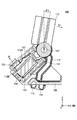
図8~図10は、一実施形態に係る操作装置100において前方への傾倒操作が行われたときの動作を説明するための図である。
図8~図10は、一実施形態に係る操作装置100において前方への傾倒操作が行われたときの動作を説明するための図である。
図8に示すように、操作装置100は、レバー部110に対する傾倒操作が行われていないとき、第1の上側ヨーク121および第2の上側ヨーク123が、永久磁石151,152からの磁着力により、永久磁石151,152の各々の上面に対して、磁着された状態となっている。すなわち、第1の上側保持部122および第2の上側保持部124が閉じた状態となっている。また、第1の下側ヨーク141および第2の下側ヨーク143が、永久磁石151,152からの磁着力により、永久磁石151,152の各々の下面に対して、磁着された状態となっている。これにより、レバー部110が、中立状態が安定的に維持された状態となっている。すなわち、第1の下側保持部142および第2の下側保持部144が閉じた状態となっている。
例えば、図9に示すように、レバー部110による前方(第1回動方向D1)への所定角度θ1となる傾倒操作が行われた際、レバー部110が、第1上側押圧部112Aによって、第1の上側ヨーク121を上方に押し上げる。このとき、第1の上側ヨーク121に対する永久磁石151,152からの磁着力により、レバー部110において、当該傾倒操作に対する抵抗力が生じる。そして、操作者が、この抵抗力に打ち勝つ前方への付勢力を、レバー部110に対して加えたとき、図9における矢印Aに示すように、第1の上側ヨーク121が、永久磁石151,152の上面に対して上方に引き剥がされる。これにより、図9に示すように、レバー部110が、シャフト137を回動軸として、回動角度が所定角度θ1となるまで、第1回動方向D1へ回動することとなる。このとき、レバー部110における上記抵抗力が急激に減少し、すなわち、レバー部110の操作が急激に軽くなるため、操作者は、この荷重変化により、第1段階目のクリック感を感じることができる。
さらに、図10に示すように、レバー部110による前方(第1回動方向D1)への所定角度θ2となる傾倒操作が行われた際、レバー部110が、第2上側押圧部112Bによって、第2の上側ヨーク123を上方に押し上げる。このとき、第2の上側ヨーク123に対する永久磁石151,152からの磁着力により、レバー部110において、当該傾倒操作に対する抵抗力が生じる。そして、操作者が、この抵抗力に打ち勝つ前方への付勢力を、レバー部110に対して加えたとき、図10における矢印Bに示すように、第2の上側ヨーク123が、永久磁石151,152の上面に対して上方に引き剥がされる。これにより、図10に示すように、レバー部110が、シャフト137を回動軸として、回動角度が所定角度θ2となるまで、第1回動方向D1へ回動することとなる。このとき、レバー部110における上記抵抗力が急激に減少し、すなわち、レバー部110の操作が急激に軽くなるため、操作者は、この荷重変化により、第2段階目のクリック感を感じることができる。
そして、レバー部110が第1回動方向D1へ傾いている状態から、操作者によるレバー部110に対する付勢力が解消されたとき、永久磁石151,152からの磁着力により、第1の上側ヨーク121および第2の上側ヨーク123が、永久磁石151,152の上面に磁着されることとなる。これに伴って、レバー部110は、シャフト137を回動軸として、第2回動方向D2に向って回動することによって、第1回動方向D1への傾きが解消され、自動的に中立状態(図8参照)に復帰することとなる。
なお、本実施形態の操作装置100は、永久磁石151,152を間に挟んで、上側ヨーク部120と下側ヨーク部140とが上下対称構造を有する。このため、本実施形態の操作装置100は、後方(第2回動方向D2)への傾倒操作がなされたときも、前方(第1回動方向D1)への傾倒操作がなされたときと同様に、当該後方への傾倒操作に対して、2段階のクリック感を付与することができる。
例えば、レバー部110による後方(第2回動方向D2)への所定角度θ1となる傾倒操作が行われた際、レバー部110が、第1下側押圧部112C(図4参照)によって、第1の下側ヨーク141を下方に押し下げる。このとき、第1の下側ヨーク141に対する永久磁石151,152からの磁着力により、レバー部110において、当該傾倒操作に対する抵抗力が生じる。そして、操作者が、この抵抗力に打ち勝つ後方への付勢力を、レバー部110に対して加えたとき、第1の下側ヨーク141が、永久磁石151,152の下面に対して下方に引き剥がされる。これにより、レバー部110が、シャフト137を回動軸として、回動角度が所定角度θ1となるまで、第2回動方向D2へ回動することとなる。このとき、レバー部110における上記抵抗力が急激に減少し、すなわち、レバー部110の操作が急激に軽くなるため、操作者は、この荷重変化により、第1段階目のクリック感を感じることができる。
さらに、レバー部110による後方(第2回動方向D2)への所定角度θ2となる傾倒操作が行われた際、レバー部110が、第2下側押圧部112D(図4参照)によって、第2の下側ヨーク143を下方に押し下げる。このとき、第2の下側ヨーク143に対する永久磁石151,152からの磁着力により、レバー部110において、当該傾倒操作に対する抵抗力が生じる。そして、操作者が、この抵抗力に打ち勝つ後方への付勢力を、レバー部110に対して加えたとき、第2の下側ヨーク143が、永久磁石151,152の下面に対して下方に引き剥がされる。これにより、レバー部110が、シャフト137を回動軸として、回動角度が所定角度θ2となるまで、第2回動方向D2へ回動することとなる。このとき、レバー部110における上記抵抗力が急激に減少し、すなわち、レバー部110の操作が急激に軽くなるため、操作者は、この荷重変化により、第2段階目のクリック感を感じることができる。
そして、レバー部110が第2回動方向D2へ傾いている状態から、操作者によるレバー部110に対する付勢力が解消されたとき、永久磁石151,152からの磁着力により、第1の下側ヨーク141および第2の下側ヨーク143が、永久磁石151,152の下面に磁着されることとなる。これに伴って、レバー部110は、シャフト137を回動軸として、第1回動方向D1に向って回動することによって、第2回動方向D2への傾きが解消され、自動的に中立状態(図8参照)に復帰することとなる。
以上説明したように、本実施形態の操作装置100は、操作レバーの傾倒操作に伴って回動するレバー部110と、レバー部110が有する回転中心軸部110Aの両外側において、回転中心軸部110Aを回動可能に挟持する第1の腕部131および第2の腕部132(一対の支持部)を有するホルダ130(保持部材)と、ホルダ130において、第1の腕部131側に保持された永久磁石151(第1の磁石)と、ホルダ130において第2の腕部132側に保持された永久磁石152(第2の磁石)とを有する磁気発生部150と、磁気発生部150と対向して配置され、レバー部110の回動に伴って磁気発生部150に対して接離動作し、当該接離動作の際に、磁気発生部150からの磁着力によって、傾倒操作に対して操作感を付与する、第1の上側ヨーク121、第2の上側ヨーク123、第1の下側ヨーク141、および第2の下側ヨーク143(磁性体)とを備え、ホルダ130は、永久磁石151と永久磁石152との間に生じる磁着力により、第1の腕部131と第2の腕部132との間隔が狭められる。
これにより、本実施形態の操作装置100は、回転中心軸部110Aにおける摺動抵抗を増加し、レバー部110の回動動作における負荷を高めることができる。したがって、本実施形態の操作装置100によれば、比較的簡単な構成により、操作部材の傾倒操作が解除された際の打撃音を抑制することができる。
また、本実施形態の操作装置100において、ホルダ130は、第1の腕部131側において永久磁石151を保持する第1磁石保持部133と、第2の腕部132側において永久磁石152を保持する第2磁石保持部134と、第1磁石保持部133と第2磁石保持部134とを連結する連結部138とを有し、永久磁石151と永久磁石152との間の磁着力によって、連結部138が弾性変形することにより、第1の腕部131と第2の腕部132との間隔が狭められる。
これにより、本実施形態の操作装置100は、レバー部110の回動動作における負荷を調整する部材を別途設ける必要なく、永久磁石151と永久磁石152との間の磁着力等に応じて、連結部138の形状等を調整して、連結部138の弾性変形し易さを調整することにより、レバー部110の回動動作における負荷を調整することができる。したがって、本実施形態の操作装置100によれば、比較的簡単な構成により、レバー部110の回動動作における負荷を調整することができる。
また、本実施形態の操作装置100において、ホルダ130は、第1磁石保持部133と、第2磁石保持部134と、連結部138とが一体的に形成されている。これにより、本実施形態の操作装置100は、レバー部110の回動動作における負荷を調整可能な連結部138を、比較的容易に形成することができる。
また、本実施形態の操作装置100において、第1の腕部131および第2の腕部132の各々は、第1の腕部131と第2の腕部132との間隔を狭める方向に弾性変形可能である。
これにより、本実施形態の操作装置100は、永久磁石151と永久磁石152との間の磁着力によって、第1の腕部131と第2の腕部132との間隔をより狭め易くすることができる。したがって、本実施形態の操作装置100によれば、レバー部110の回動動作における負荷を容易に高めることができる。
また、本実施形態の操作装置100において、第1の腕部131は、ホルダ130における一方側の側壁部130Lにおいて、当該第1の腕部131の延在方向に沿って形成されたスリット135により、当該第1の腕部131の弾性変形可能な長さが規定され、第2の腕部132は、ホルダ130における他方側の側壁部130Rにおいて、当該第2の腕部132の延在方向に沿って形成されたスリット136により、当該第2の腕部132の弾性変形可能な長さが規定される。
これにより、本実施形態の操作装置100は、第1の腕部131および第2の腕部132の弾性変形し易さを、スリット135,136により容易に調整することができる。したがって、本実施形態の操作装置100によれば、レバー部110の回動動作における負荷を容易に調整することができる。
以上、本発明の一実施形態について詳述したが、本発明はこれらの実施形態に限定されるものではなく、特許請求の範囲に記載された本発明の要旨の範囲内において、種々の変形又は変更が可能である。
例えば、上記実施形態の操作装置100では、ホルダ130が第1の腕部131および第2の腕部132を有しており、第1の腕部131および第2の腕部132が弾性変形することにより、一対の支持部の間隔を狭めるようにしているが、これに限らない。例えば、ホルダ130が第1の腕部131および第2の腕部132を有さずに、ホルダ130自体が弾性変形することにより、一対の支持部の間隔を狭めるようにしてもよい。
また、例えば、上記実施形態の操作装置100では、第1磁石保持部133と第2磁石保持部134とを連結する連結部138を設けて、当該連結部138が弾性変形することにより、第1磁石保持部133と第2磁石保持部134との間隔を狭めて、一対の支持部の間隔を狭めるようにしているが、これに限らない。例えば、第1磁石保持部133と第2磁石保持部134とを連結する連結部138を設けずに、永久磁石151,152の相互の磁着力によって、第1磁石保持部133と第2磁石保持部134との間隔を狭めて、一対の支持部の間隔を狭めるようにしてもよい。
本国際出願は、2018年12月12日に出願した日本国特許出願第2018-232647号に基づく優先権を主張するものであり、当該出願の全内容を本国際出願に援用する。
100 操作装置
110 レバー部
120 上側ヨーク部(磁性体保持部)
121 第1の上側ヨーク(磁性体)
122 第1の上側保持部
123 第2の上側ヨーク(磁性体)
124 第2の上側保持部
130 ホルダ(軸部保持部材)
130L 側壁部(一方側の側壁部)
130R 側壁部(他方側の側壁部)
131 第1の腕部(一方の支持部)
132 第2の腕部(他方の支持部)
133 第1磁石保持部
134 第2磁石保持部
135,136 スリット
137 シャフト
138 連結部
140 下側ヨーク部(磁性体保持部)
141 第1の下側ヨーク(磁性体)
142 第1の下側保持部
143 第2の下側ヨーク(磁性体)
144 第2の下側保持部
150 磁気発生部
151 永久磁石(第1の磁石)
152 永久磁石(第2の磁石)
110 レバー部
120 上側ヨーク部(磁性体保持部)
121 第1の上側ヨーク(磁性体)
122 第1の上側保持部
123 第2の上側ヨーク(磁性体)
124 第2の上側保持部
130 ホルダ(軸部保持部材)
130L 側壁部(一方側の側壁部)
130R 側壁部(他方側の側壁部)
131 第1の腕部(一方の支持部)
132 第2の腕部(他方の支持部)
133 第1磁石保持部
134 第2磁石保持部
135,136 スリット
137 シャフト
138 連結部
140 下側ヨーク部(磁性体保持部)
141 第1の下側ヨーク(磁性体)
142 第1の下側保持部
143 第2の下側ヨーク(磁性体)
144 第2の下側保持部
150 磁気発生部
151 永久磁石(第1の磁石)
152 永久磁石(第2の磁石)
Claims (5)
- 操作レバーの傾倒操作に伴って回動するレバー部と、
前記レバー部が有する回転中心軸部の両外側において、前記回転中心軸部を回動可能に挟持する一対の支持部を有する軸部保持部材と、
前記軸部保持部材において、前記一対の支持部のうちの一方の支持部の側に保持された第1の磁石と、前記軸部保持部材において、前記一対の支持部のうちの他方の支持部の側に保持された第2の磁石とを有する磁気発生部と、
前記磁気発生部と対向して配置され、前記レバー部の回動に伴って前記磁気発生部に対して接離動作し、前記磁気発生部からの磁着力によって前記傾倒操作に対して操作感を付与する磁性体と
を備え、
前記軸部保持部材は、
前記第1の磁石と前記第2の磁石との間に生じる磁着力によって、前記一対の支持部の間隔が狭められる
ことを特徴とする操作装置。 - 前記軸部保持部材は、
前記一方の支持部の側において前記第1の磁石を保持する第1磁石保持部と、
前記他方の支持部の側において前記第2の磁石を保持する第2磁石保持部と、
前記第1磁石保持部と前記第2磁石保持部とを連結する連結部と
を有し、
前記第1の磁石と前記第2の磁石との間の磁着力によって、前記連結部が弾性変形することにより、前記一対の支持部の間隔が狭められる
ことを特徴とする請求項1に記載の操作装置。 - 前記軸部保持部材は、
前記第1磁石保持部と、前記第2磁石保持部と、前記連結部とが一体的に形成されている
ことを特徴とする請求項2に記載の操作装置。 - 前記磁性体は、一対の回転中心腕部を備えた磁性体保持部に保持されており、
前記一方の支持部は、
前記回転中心軸部の一方側と前記磁性体保持部の一方側の回転中心腕部を回動可能に支持し、
前記他方の支持部は、
前記回転中心軸部の他方側と前記磁性体保持部の他方側の回転中心腕部を回動可能に支持しており、
前記一対の支持部の間隔を狭める方向に弾性変形して、前記回転中心軸部と前記磁性体保持部の回転中心腕部のそれぞれが互いに接触した状態で挟持される
ことを特徴とする請求項1から3のいずれか一項に記載の操作装置。 - 前記一方の支持部は、
前記軸部保持部材の一方側の側壁部において、当該一方の支持部の延在方向に沿って形成されたスリットにより、当該一方の支持部の弾性変形可能な長さが規定され、
前記他方の支持部は、
前記軸部保持部材の他方側の側壁部において、当該他方の支持部の延在方向に沿って形成されたスリットにより、当該他方の支持部の弾性変形可能な長さが規定される
ことを特徴とする請求項4に記載の操作装置。
Applications Claiming Priority (2)
| Application Number | Priority Date | Filing Date | Title |
|---|---|---|---|
| JP2018-232647 | 2018-12-12 | ||
| JP2018232647A JP2022024209A (ja) | 2018-12-12 | 2018-12-12 | 操作装置 |
Publications (1)
| Publication Number | Publication Date |
|---|---|
| WO2020121695A1 true WO2020121695A1 (ja) | 2020-06-18 |
Family
ID=71076309
Family Applications (1)
| Application Number | Title | Priority Date | Filing Date |
|---|---|---|---|
| PCT/JP2019/043505 Ceased WO2020121695A1 (ja) | 2018-12-12 | 2019-11-06 | 操作装置 |
Country Status (2)
| Country | Link |
|---|---|
| JP (1) | JP2022024209A (ja) |
| WO (1) | WO2020121695A1 (ja) |
Cited By (2)
| Publication number | Priority date | Publication date | Assignee | Title |
|---|---|---|---|---|
| DE102024107544A1 (de) * | 2024-03-15 | 2025-09-18 | Signata GmbH | Schalteinheit |
| WO2025190441A1 (de) * | 2024-03-15 | 2025-09-18 | Signata GmbH | Schalteinheit |
Families Citing this family (1)
| Publication number | Priority date | Publication date | Assignee | Title |
|---|---|---|---|---|
| JP2024155613A (ja) * | 2023-04-21 | 2024-10-31 | 株式会社東海理化電機製作所 | シフト装置 |
Citations (3)
| Publication number | Priority date | Publication date | Assignee | Title |
|---|---|---|---|---|
| WO2018042724A1 (ja) * | 2016-09-05 | 2018-03-08 | アルプス電気株式会社 | 操作装置 |
| WO2018100924A1 (ja) * | 2016-11-29 | 2018-06-07 | アルプス電気株式会社 | 操作装置及びその操作装置を用いた車両用シフト装置 |
| JP2018128841A (ja) * | 2017-02-08 | 2018-08-16 | 株式会社セガゲームス | レバー入力装置 |
-
2018
- 2018-12-12 JP JP2018232647A patent/JP2022024209A/ja active Pending
-
2019
- 2019-11-06 WO PCT/JP2019/043505 patent/WO2020121695A1/ja not_active Ceased
Patent Citations (3)
| Publication number | Priority date | Publication date | Assignee | Title |
|---|---|---|---|---|
| WO2018042724A1 (ja) * | 2016-09-05 | 2018-03-08 | アルプス電気株式会社 | 操作装置 |
| WO2018100924A1 (ja) * | 2016-11-29 | 2018-06-07 | アルプス電気株式会社 | 操作装置及びその操作装置を用いた車両用シフト装置 |
| JP2018128841A (ja) * | 2017-02-08 | 2018-08-16 | 株式会社セガゲームス | レバー入力装置 |
Cited By (2)
| Publication number | Priority date | Publication date | Assignee | Title |
|---|---|---|---|---|
| DE102024107544A1 (de) * | 2024-03-15 | 2025-09-18 | Signata GmbH | Schalteinheit |
| WO2025190441A1 (de) * | 2024-03-15 | 2025-09-18 | Signata GmbH | Schalteinheit |
Also Published As
| Publication number | Publication date |
|---|---|
| JP2022024209A (ja) | 2022-02-09 |
Similar Documents
| Publication | Publication Date | Title |
|---|---|---|
| US20180194229A1 (en) | Motor vehicle operating device with haptic feedback | |
| JP5930226B2 (ja) | 多方向入力操作装置及び該多方向入力操作装置を用いた車両用シフト装置 | |
| US8976012B2 (en) | Touch panel assembly with haptic effects and method of manufacturuing thereof | |
| JP2022024209A (ja) | 操作装置 | |
| US10995849B2 (en) | Operation device and vehicular shifting apparatus using operation device | |
| US8613236B2 (en) | Shift lever device | |
| US11117466B2 (en) | Operation device and vehicular shifting apparatus using operation device | |
| EP3362874A1 (fr) | Actionneur de module d'interface tactile, module d'interface tactile et procédé de génération d'un retour haptique | |
| JP6422079B2 (ja) | 操作装置及び該操作装置を用いた車両用シフト装置 | |
| JP6560822B2 (ja) | 操作装置、該操作装置を用いた車両用シフト装置 | |
| CN108463786A (zh) | 包括用于输出触觉反馈的驱动单元的用于机动车辆的操作者单元和机动车辆 | |
| KR101327044B1 (ko) | 차량의 페달장치 | |
| KR20110050848A (ko) | 가속페달 장치의 킥 다운 스위치 | |
| US10802528B2 (en) | Operating device | |
| JP6403137B2 (ja) | 操作装置及び該操作装置を用いた車両用シフト装置 | |
| JP6889097B2 (ja) | 操作装置 | |
| JPWO2019013048A1 (ja) | シフト装置 | |
| JP6452154B2 (ja) | 操作装置、該操作装置を用いた車両用シフト装置 | |
| EP3736656B1 (en) | Operation device | |
| JP7835615B2 (ja) | 多方向入力装置 | |
| JP6619887B2 (ja) | 操作装置 | |
| EP3739423B1 (en) | Operation device | |
| JP6563605B2 (ja) | 操作装置 | |
| JP5848953B2 (ja) | シフトレバー装置 | |
| CN112969989B (zh) | 输入装置 |
Legal Events
| Date | Code | Title | Description |
|---|---|---|---|
| 121 | Ep: the epo has been informed by wipo that ep was designated in this application |
Ref document number: 19896587 Country of ref document: EP Kind code of ref document: A1 |
|
| NENP | Non-entry into the national phase |
Ref country code: DE |
|
| 122 | Ep: pct application non-entry in european phase |
Ref document number: 19896587 Country of ref document: EP Kind code of ref document: A1 |
|
| NENP | Non-entry into the national phase |
Ref country code: JP |