WO2020116803A1 - 냉각 및 가열이 가능한 신축성 유연 웨어러블 열전소자 - Google Patents
냉각 및 가열이 가능한 신축성 유연 웨어러블 열전소자 Download PDFInfo
- Publication number
- WO2020116803A1 WO2020116803A1 PCT/KR2019/015294 KR2019015294W WO2020116803A1 WO 2020116803 A1 WO2020116803 A1 WO 2020116803A1 KR 2019015294 W KR2019015294 W KR 2019015294W WO 2020116803 A1 WO2020116803 A1 WO 2020116803A1
- Authority
- WO
- WIPO (PCT)
- Prior art keywords
- electrode
- thermoelectric
- thermoelectric material
- thermoelectric element
- pair
- Prior art date
- Legal status (The legal status is an assumption and is not a legal conclusion. Google has not performed a legal analysis and makes no representation as to the accuracy of the status listed.)
- Ceased
Links
Images



Classifications
-
- H—ELECTRICITY
- H10—SEMICONDUCTOR DEVICES; ELECTRIC SOLID-STATE DEVICES NOT OTHERWISE PROVIDED FOR
- H10N—ELECTRIC SOLID-STATE DEVICES NOT OTHERWISE PROVIDED FOR
- H10N10/00—Thermoelectric devices comprising a junction of dissimilar materials, i.e. devices exhibiting Seebeck or Peltier effects
- H10N10/10—Thermoelectric devices comprising a junction of dissimilar materials, i.e. devices exhibiting Seebeck or Peltier effects operating with only the Peltier or Seebeck effects
- H10N10/17—Thermoelectric devices comprising a junction of dissimilar materials, i.e. devices exhibiting Seebeck or Peltier effects operating with only the Peltier or Seebeck effects characterised by the structure or configuration of the cell or thermocouple forming the device
-
- H—ELECTRICITY
- H10—SEMICONDUCTOR DEVICES; ELECTRIC SOLID-STATE DEVICES NOT OTHERWISE PROVIDED FOR
- H10N—ELECTRIC SOLID-STATE DEVICES NOT OTHERWISE PROVIDED FOR
- H10N10/00—Thermoelectric devices comprising a junction of dissimilar materials, i.e. devices exhibiting Seebeck or Peltier effects
- H10N10/01—Manufacture or treatment
-
- H—ELECTRICITY
- H10—SEMICONDUCTOR DEVICES; ELECTRIC SOLID-STATE DEVICES NOT OTHERWISE PROVIDED FOR
- H10N—ELECTRIC SOLID-STATE DEVICES NOT OTHERWISE PROVIDED FOR
- H10N10/00—Thermoelectric devices comprising a junction of dissimilar materials, i.e. devices exhibiting Seebeck or Peltier effects
- H10N10/80—Constructional details
- H10N10/81—Structural details of the junction
-
- H—ELECTRICITY
- H10—SEMICONDUCTOR DEVICES; ELECTRIC SOLID-STATE DEVICES NOT OTHERWISE PROVIDED FOR
- H10N—ELECTRIC SOLID-STATE DEVICES NOT OTHERWISE PROVIDED FOR
- H10N10/00—Thermoelectric devices comprising a junction of dissimilar materials, i.e. devices exhibiting Seebeck or Peltier effects
- H10N10/80—Constructional details
- H10N10/85—Thermoelectric active materials
Definitions
- the present invention relates to a thermoelectric element that can be cooled or heated and is flexible and stretchable.
- Smart clothing is a clothing in which various digital devices are built in the clothing so that the clothing itself senses external stimuli and responds to the conditions set by itself.
- Various types of smart clothing such as a wearable computer, a built-in MP3, and a built-in heating wire, have been proposed, and among them, a limited market is established as a typical smart clothing as a heating clothing with a built-in heating wire.
- Heated clothing has the advantage of being able to generate heat itself and perform excellent thermal insulation, but since it is a form in which a thermoelectric element with limited elasticity is inserted into a pocket of a garment or attached to a garment, it is heavy and uncomfortable when worn. There was a problem difficult to secure.
- thermoelectric element forms a second electrode on a ceramic lower substrate such as alumina, forms a thermoelectric material composed of N-type and P-type semiconductors on the electrode surface, and an N-type thermoelectric material and a P-type thermoelectric material form the first electrode. It is usually manufactured in a structure that is connected in series through.
- thermoelectric element has a disadvantage in that it is difficult to apply to a field requiring flexibility by using a ceramic substrate having no flexible characteristics or a metal substrate coated with a non-conductive thin film.
- thermoelectric element using a flexible material as a base substrate.
- heat is radiated to the outside by applying a heat exchanger and a fan, which are essentially fixed structures, and since the flexible thermoelectric element cannot apply such a rigid structure type thermal system, the heat generated on the system There is a problem that is accumulated inside and degrades device performance during cooling.
- thermoelectric element In the case of a conventional rigid thermoelectric element or a flexible thermoelectric element, it is difficult to expand and contract according to the movement of the human body, so it is difficult to tailor it according to the bending information of the human body, so it is insufficient to be applied to wearable devices such as smart clothing.
- Patent Document 1 KR1020170049402 A
- Patent Document 2 KR1020170056853 A
- thermoelectric element that has flexibility and elasticity, and can implement cooling and heating.
- One embodiment of the present invention is to provide a wearable device to which a flexible and elastic thermoelectric element is applied.
- thermoelectric material A first electrode and a second electrode that are deformable and electrically connected to both sides of the thermoelectric material, and one side of which is opposite to each other; A pair of first elastic composites positioned to be in contact with at least a portion of each side of each of the first electrode and the second electrode; A thermoelectric element having elasticity and flexibility may be provided, including; a pair of second elastic composites positioned to be in contact with each other side of the first electrode and the second electrode, respectively.
- first elastic composite and the second elastic composite may include an elastomer and a metal nanomaterial.
- first elastic composite and the second elastic composite may include the metal nanomaterial in a content of 20 to 60 wt% in 100 wt% of each elastic composite.
- first electrode and the second electrode may be copper electrodes.
- first electrode and the second electrode is a pair of thermoelectric material contacts formed in a circular shape; And a connection portion formed to have a curvature on a plane, and connecting the pair of thermoelectric contact portions to each other.
- first electrode and the second electrode is a pair of thermoelectric material contacts formed in a circular shape; And a connecting portion formed to have a curvature on a plane, and connecting the pair of thermoelectric contact portions to each other, wherein the thermoelectric material is positioned to contact the thermoelectric contact portion and the first electrode or the second electrode. It can be electrically connected.
- first electrode and the second electrode is a pair of thermoelectric material contacts formed in a circular shape; And a connecting portion formed to have a curvature on a plane, and connecting the pair of thermoelectric material contacting portions to each other, wherein the first elastic composite may be positioned to contact one side of at least a portion of the connecting portion.
- the connecting portion may be formed to a width of 500 to 700 ⁇ m.
- first elastic composite and the second elastic composite positioned with the first electrode or the second electrode therebetween may be in direct contact with each other.
- thermoelectric material At least one pair of elastic composites having flexibility and elasticity; And a first electrode and a second electrode that are deformable and are at least partially drawn in and disposed on the elastic composite body, and at least partially electrically connected to both sides of the thermoelectric material, wherein the thermoelectric element having elasticity and flexibility Can be provided.
- the first step of preparing the electrode material A second step of placing the electrode material on one side of the thermally conductive elastic composite and processing it with a laser to form an electrode; A third step of applying and heating the thermally conductive elastic composite on the structure prepared in the second step; A fourth step of removing the at least a portion of the elastic composite applied in the third step to expose the electrode, thereby producing a first structure in which a portion of the electrode is exposed; A fifth step of preparing a second structure by repeating the first to fourth steps; And a sixth step of connecting the first structure and the second structure with a thermoelectric material interposed therebetween, and a method for manufacturing a thermoelectric device having elasticity and flexibility may be provided.
- the first step may be performed by coating the electrode material with a polyimide solution.
- the elastic composite may be prepared by mixing an elastomer and a metal nanomaterial.
- the heating of the third step may be performed for 5 to 20 minutes at a temperature of 50 to 70 °C.
- the electrode is a pair of thermoelectric material contact portion formed in a circular shape; And a connection portion formed to have a curvature on a plane, and connecting the pair of thermoelectric contact portions to each other. At least a portion of the thermoelectric contact portion may be exposed in the fourth step.
- the sixth step may be connected by soldering, heating and pressing between the thermoelectric material and the electrode.
- thermoelectric element having excellent flexibility, stretchability, and thermal conductivity and having excellent efficiency when cooling or heating may be provided.
- thermoelectric element capable of easily converting temperature
- the temperature can be adjusted in a faster time than relying on natural convection, so that the user desires when applied to a device that performs warming or cooling in contact with the body. It can provide heat quickly.
- thermoelectric element since an electrode having a specified structure is applied, it is easy to control so that heat generated by the thermoelectric element does not accumulate therein even if it does not include a fan structure such as a conventional rigid thermoelectric element during cooling. Can be reduced.
- thermoelectric element 1 is a cross-sectional view of a thermoelectric element according to an embodiment of the present invention
- FIG. 2 is a plan view of an electrode of an embodiment of the present invention
- Figure 3 confirms the results of the optimization according to the line width of the electrode of an embodiment of the present invention
- Figure 4 shows the direction of heat conduction during cooling of an embodiment of the present invention
- Figure 5 confirms the effect of the thermal conductivity according to the mixing ratio of the elastomer and the metal nanomaterial in the elastic composite of an embodiment of the present invention
- thermoelectric element 6 is a cross-sectional view of a thermoelectric element according to an embodiment of the present invention.
- thermoelectric element 8 is a photo of a thermoelectric element according to an embodiment of the present invention.
- thermoelectric element 9 is a photograph showing the elasticity of the thermoelectric element according to an embodiment of the present invention.
- Figure 10 shows the experimental results of the wearable device including a thermoelectric element of an embodiment of the present invention
- thermoelectric element 11 is a diagram showing a manufacturing form according to a manufacturing step according to a method of manufacturing a thermoelectric element according to an embodiment of the present invention.
- thermoelectric element may be provided.
- 1 shows a thermoelectric element according to an embodiment of the present invention.
- the thermoelectric element 10 according to an embodiment of the present invention includes a thermoelectric material 110; A pair of electrodes 120 and 130 respectively connected to both sides of the thermoelectric material 110; It may include a pair of elastic composites (140, 150) positioned to be in contact with each of at least a portion of the pair of electrodes (120, 130).
- the thermoelectric material 110 may include a p-type or n-type semiconductor. Specifically, the thermoelectric material 110 may be a p-type thermoelectric material including a p-type semiconductor or an n-type thermoelectric material including an n-type semiconductor. The p-type thermoelectric material and the n-type thermoelectric material may be electrically connected by electrodes 120 and 130 to be described later.
- the thermoelectric material 110 is silicon (Si), aluminum (Al), calcium (Ca), sodium (Na), germanium (Ge), iron (Fe), lead (Pb), antimony (Sb), tellurium ( Te), bismuth (Bi), cobalt (Co), cerium (Ce), tin (Sn), nickel (Ni), copper (Cu), sodium (Na), potassium (K), platinum (Pt), ruthenium ( Ru), rhodium (Rh), gold (Au), tungsten (W), palladium (Pd), titanium (Ti), tantalum (Ta), molybdenum (Mo), hafnium (Hf), lanthanum (La), iridium ( Ir), silver (Ag), boron (B), gallium (Ga), selenium (Se), and indium (In) may include at least one compound selected from the group consisting of, but is not limited to.
- thermoelectric material 110 when the thermoelectric material 110 is an n-type thermoelectric material, selenium (Se), nickel (Ni), aluminum (Al), copper (Cu), silver (Ag), lead (Pb), boron ( B), gallium (Ga), tellurium (Te), bismuth (Bi) and may be composed of at least one compound selected from the group consisting of indium (In), and in the case of p-type thermoelectric material, antimony ( Sb), nickel (Ni), aluminum (Al), copper (Cu), silver (Ag), lead (Pb), boron (B), gallium (Ga), tellurium (Te), bismuth (Bi) and indium It may be configured to include at least one compound selected from the group consisting of (In).
- the thermoelectric material 110 may have a fin or column shape.
- the column shape may be a cylindrical or polygonal column. In this embodiment, it will be described as having a square pillar shape.
- the diameter of the thermoelectric material 110 is not limited, but may be in micrometer units.
- the pair of electrodes 120 and 130 may be formed of an inorganic material having excellent electrical conductivity and being deformable. At this time,'deformable' means that it can be flexed or bent flexibly.
- the inorganic material include nickel (Ni), aluminum (Al), copper (Cu), ruthenium (Ru), rhodium (Rh), gold (Au), tungsten (W), cobalt (Co), and palladium ( At least one selected from the group consisting of Pd), titanium (Ti), tantalum (Ta), iron (Fe), molybdenum (Mo), hafnium (Hf), lanthanum (La), iridium (Ir) and silver (Ag) It may be formed, but is not limited to this. In this embodiment, the pair of electrodes 120 and 130 will be described as being copper electrodes.
- the pair of electrodes 120 and 130 may be connected to one side and the other side of the thermoelectric material 110, respectively.
- the meaning of'connection' is not limited as long as it is electrically connected, for example, a connection of the pair of electrodes 120 and 130 and the thermoelectric material 110 may be made through a conductive adhesive or soldering.
- an electrode connected to one side of the thermoelectric material 110 among the pair of electrodes 120 and 130 is connected to the other side of the thermoelectric material 110 as a first electrode 120.
- the electrode will be referred to as the second electrode.
- the n-type thermoelectric material and the p-type thermoelectric material may be connected through the first electrode 120 and the second electrode 130.
- thermoelectric material 110 may contact the opposite surfaces of the first electrode 120 and the second electrode 130.
- an electrode used for connection of the thermoelectric material 110 may have a specific structure to be described later, thereby implementing tension corresponding to a wearable purpose.
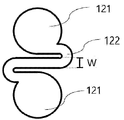
- the first electrode and the second electrode 130 may be formed in shapes corresponding to each other. An example of shapes of the first electrode 120 and the second electrode 130 is illustrated in FIG. 2. Referring to FIG. 2, the first electrode 120 and the second electrode 130 include a pair of thermoelectric material contact parts 121; And a connection part 122.
- thermoelectric material contacting portion 121 is a portion to be connected to the thermoelectric material 110, through which at least a portion of the electrodes 120 and 130 of this embodiment may be electrically connected to both sides of the thermoelectric material 110, respectively.
- the thermoelectric material 110 is positioned to be in contact with the thermoelectric material contact portion 121 to be electrically connected to the first electrode 120 or the second electrode 130, wherein the thermoelectric material contact portion 121 May contact different thermoelectric materials 110.
- one of the pair of thermoelectric material contact parts 121 may contact the first thermoelectric material, and the other of the pair of thermoelectric material contact parts 121 may contact the second thermoelectric material.
- the first thermoelectric material may be an n-type thermoelectric material
- the second thermoelectric material may be a p-type thermoelectric material.
- the shape of the thermoelectric material contact portion 121 is not particularly limited, and may be formed including a flat surface. In order to reduce the mechanical resistance received when bending the thermoelectric element of one embodiment of the present invention to be manufactured in various directions, it may be formed to have a curved flat surface that does not include an angle or an edge. In this embodiment, it will be described that the flat surface is formed in a circular shape.
- the thermoelectric material contact portion 121 may be formed to have an area equal to or greater than a surface where the thermoelectric material 110 contacts the electrode. In the present embodiment, the thermoelectric material 110 has a square column shape, and one side of the quadrangular shape is connected to the thermoelectric material contacting portion 121, and the thermoelectric material contacting portion 121 has the square shape inside. It is described as being a large circular shape that can be included.
- the pair of thermoelectric material contact parts 121 may be connected to each other through the connection part 122.
- the connection part 122 may be formed to have a curvature.
- the curvature may be formed to have a curvature on a plane where the pair of thermoelectric material contact parts 121 and the connection part 122 are placed.
- the directionality is described by using the horizontal direction as the X axis, the vertical direction as the Y axis, and the horizontal and vertical directions as the Z axis crossing vertically in three dimensions, based on the drawing shown in FIG. 2, It may be formed to have a curvature on a plane consisting of the X-axis and Y-axis.
- the connecting portion 122 may be formed to exhibit curvature on the X-axis or Y-axis rather than the Z-axis. Alternatively, the curvature may be formed in the X and Y axes, not the Z axis. In this embodiment, it will be described that the connecting portion 122 is formed in an S-shape having a curvature in the Y-axis direction.
- the thermoelectric material contacting portion 121 can be flexibly connected through the connection portion 122 having a curvature as described above, through which the thermoelectric material 110 contacting the thermoelectric material contacting portion 121 Can be flexible and elastic in three dimensions. For example, when a tensile force is applied in the Y-axis direction, the curvature of the connecting portion 122 is reduced, and the electrodes 120 and 130 can be elastically stretched.
- thermoelectric element itself operates according to the electrical distribution of electrons and holes, the electrical resistance acts as a very important element in the thermoelectric element.
- the thinner the line width of the electrode the stronger the mechanical stress. Therefore, instead of fixing the thickness when designing the electrode, set the line width as a variable, and apply it to the electrode during 50% tension. Optimization is performed by calculating the product of stress and electrical resistance through simulation, and the results are shown in FIG. 3.
- the line width means the line width W of the connecting portion 122 shown in FIG. 2. Referring to FIG. 3, it can be seen that the slope of the product of stress and resistance multiplied within a range in which the line width of the electrode is 600 ⁇ m or more.
- the line width of the electrode becomes too thick, a problem occurs in that the mechanical strength of the electrode is lowered, and the line width for optimization is based on 600 ⁇ m, considering the wearable performance and mechanical strength of the thermoelectric element, electrical conductivity.
- the line width of the connection portion 122 for optimizing electrode performance that can maintain excellent elasticity while maintaining a thickness of 500 to 700 ⁇ m may be formed.
- the first electrode 120 and the second electrode 130 may be disposed to contact the pair of elastic composites 140 and 150, respectively. At this time, each of the electrodes 120 and 130 may be disposed at least partially in the elastic composites 140 and 150. Through this, the elastic composite may be disposed to contact one side and the other side which are opposite surfaces of the first electrode 120 and the second electrode 130.
- the elastic composites 140 and 150 have flexibility and elasticity, and may include an elastomer and a metal nanomaterial.
- the elastomer is not particularly limited as long as it is a material having elasticity and flexibility, and may be, for example, a silicone polymer series.
- the metal nanomaterial is not particularly limited as long as it is an inorganic material having a nano-sized size, and may be, for example, nano-silver particles.
- the elastic composites 140 and 150 which are synthetic materials including an elastomer and a metal nanomaterial, do not show electrical conductivity but can improve thermal properties.
- the elastic composites 140 and 150 may be prepared by mixing a metal nanomaterial having excellent conductivity in an elastic polymer capable of freely processing a shape, and the thermoelectric element of this embodiment is made of copper for the elastic composites 140 and 150.
- the thermal conductivity of the thermoelectric element can be improved by thinly applying the electrodes 120 and 130. This can be applied to a surface to promote heat transfer, and heat generated on the system can be prevented from deteriorating and deteriorating the performance of the thermoelectric element during cooling.
- the thermoelectric element of one embodiment of the present invention to which it is applied can increase the heat exchanged during cooling or heating, thereby improving the efficiency of the thermoelectric element.
- thermoelectric element of this embodiment When the thermoelectric element of this embodiment is attached to the human body and cooled, the direction and heat dissipation improvement according to the application of the elastic composites 140 and 150 are illustrated in FIG. 4.
- the direction of heat conduction is indicated by an arrow, and the heat conduction toward the side not contacting the human body 20 means heat dissipation.
- one side (A) of the thermoelectric material 110 includes a cooling unit, and the other side (B) includes a heating unit.
- an air layer exists between the electrodes 120 and 130 and the elastic composites 140 and 150 which are disposed to face each other with the thermoelectric material 110 interposed therebetween, and the heat conduction from other directions not touching the human body 20 is It can be blocked.
- the results of confirming the effect of thermal conductivity according to the mixing weight ratio of the elastomer and the metal nanomaterial are shown in FIG. 5.
- the content of the metal nanomaterials contained exceeds 60 wt% based on the total of 100 wt% of the elastic composites (140, 150)
- the dispersibility of the metal nanomaterials decreases, resulting in problems such as agglomeration between particles.
- the elastic composite (140,150) containing the metal nanomaterial at 60wt% was found to be more than 6 times superior in thermal conductivity.
- the mixing ratio of the elastomer and the metal nanomaterial may include metal nanomaterials in an amount of 20 to 60wt% based on 100wt% of the total of the elastic composites 140 and 150.
- it will be described as using an elastic composite (140,150) containing a metal nanomaterial with a content of 60wt%.
- the pair of elastic composites may include first elastic composites 141 and 151 and second elastic composites 142 and 152, respectively.
- the elastic composite may be respectively manufactured in two different stages. Accordingly, in the description of the present embodiment, the elastic composite is distinguished, and it will be described as including a pair of first elastic composites 141 and 151 and a pair of second elastic composites 142 and 152. It is for convenience only, and the difference between the first elastic composites 141 and 151 and the second elastic composites 142 and 152 is not newly generated by the classification.
- the pair of first elastic composites 141 and 151 may be positioned to contact at least a portion of the opposite surfaces of the first electrode 120 and the second electrode 130, respectively.
- the pair of second elastic composites 142 and 152 may be positioned to contact at least a portion of the other side surfaces of the first electrode 120 and the second electrode 130, respectively.
- the first elastic composite (141,151) may be positioned to contact at least a portion of the opposite surface of the electrode (120 130).
- the electrodes 120 and 130 may be positioned to contact at least a portion of one side that is an opposite surface of the connection portion 122.
- the second elastic composite (142,152) may be positioned to contact the entire surface of the other side of the electrode (120 130).
- connection part 122 is at least partially contacted by the first elastic composites 141 and 151 and the second elastic composites 142 and 152, thereby preventing deterioration of mechanical properties and improving durability.
- the first elastic composites 141 and 152 and the second elastic composites 142 and 152 are positioned with the first electrode 120 or the second electrode 130 therebetween, and are not in contact with the electrodes 120 and 130, respectively.
- the parts facing each other can be directly in contact with each other.
- the electrodes 120 and 130 of the present embodiment may be in contact with both the first elastic composites 141 and 151 and the second elastic composites 142 and 152, and may be disposed at least partially in the elastic composite.
- thermoelectric element of one embodiment of the present invention can perform both cooling and heating according to the direction of the current. Through this, if the direction of the current is changed after cooling or heating is finished, the room temperature can be reached in a faster time than relying on natural convection.
- this function performed by changing the direction of the current is referred to as an inverse mode, and relying on natural convection is set to a normal mode. Cooling and heating were performed in an inverse mode and a normal mode, respectively, and the time to reach the room temperature at the changed temperature was again measured, and the results of comparison are shown in FIG. 7. In FIG.
- thermoelectric element to which the elastic composites 140 and 150 are applied is illustrated in FIG. 8.
- the thermoelectric element according to an embodiment of the present invention while exhibiting elasticity through the above-described thermally conductive elastic composites 140 and 150, can improve the performance of the element during cooling and improve heat exchange with the human body when in contact with the human body. have.
- the thermoelectric element according to an embodiment of the present invention does not require a huge device and can be formed into a compact sized system, requires flexibility and elasticity according to various shapes, and is difficult to apply to a large system. It is suitable to apply to.
- thermoelectric device system for attaching to various shapes. Since the wearable electronic device to which the thermoelectric element of one embodiment of the present invention is applied can perform both cooling and heating, it can quickly return to normal temperature after cooling or heating furnace operation, so that the wearer can quickly provide the desired thermal feeling.
- a wearable device including the above-described thermoelectric element may be provided.
- the wearable device according to the present invention may include a thermoelectric element according to the present invention, and a wearing part to which the thermoelectric element is attached and formed to contact the human body.
- the wearable portion of the wearable device may appear in various types of clothes that can be worn by the wearer, but may preferably be gloves that can be worn in the hands of the wearer.
- the glove may include at least one resin part that accommodates the wearer's finger, and the thermoelectric element may be attached to one end of the resin part.
- thermoelectric element according to the present invention can also be attached to a curved shape, and can be stretched according to the movement of the skin by being in close contact with the skin of the human body, and the thermoelectric element may be attached to a part in contact with the palm of the wearer, which It can be applied to any part of the wearable part that can experience a virtual thermal environment.
- thermoelectric element according to an embodiment of the present invention is a structure that is attached to a human body and is stretchable.
- the wearable device of an embodiment of the present invention when the wearable device of an embodiment of the present invention is in contact with an object having a specific temperature in virtual reality, it is possible to provide a realistic thermal environment. This applies and algorithmizes the thermal conductivity coefficient of the object when it comes into contact with an object having a temperature existing on the virtual reality, so that the speed and degree of cooling and heating of the thermoelectric element when contacting different objects on the virtual reality Can be adjusted.
- heat exchange may be performed through the inverse mode and the normal mode as described above. 10 shows an example of an experiment for a temperature change when a wearable device including a thermoelectric element according to an embodiment of the present invention is contacted with an object on a virtual reality.
- a method of manufacturing a thermoelectric element includes a first step of preparing an electrode material (S1); A second step (S2) of forming the electrode by processing the laser with the electrode material on one side of the thermally conductive elastic composite; A third step (S3) of applying and heating the thermally conductive elastic composite on the structure prepared in the second step; A fourth step (S4) of exposing the electrode by removing at least a portion of the elastic composite applied in the third step to produce a first structure in which a portion of the electrode is exposed; A fifth step (S5) of repeating the first to fourth steps to prepare a second structure; And it may include a sixth step (S6) for connecting the first structure and the second structure with a thermoelectric material therebetween.
- the manufacturing form according to the method for manufacturing a thermoelectric element according to an embodiment of the present invention is illustrated in each manufacturing step and is illustrated in FIG. 11.
- the first step (S1) may be performed by coating the electrode material with a flexible polymer solution.
- the polymer may be, for example, polyimide, but is not limited thereto.
- the coating may be performed by applying a polymer solution to the electrode material foil and then heating.
- the polyimide solution is applied to the copper foil and 3 to 5 minutes at 120 to 150°C, preferably 140°C, preferably
- This step can be carried out by heating at ambient conditions for 4 minutes and heating at 230 to 270°C, preferably 250°C under a nitrogen environment for 40 to 80 minutes, preferably for 1 hour.
- the electrode may be formed to have the above-described specific structure.
- it may be formed to include a pair of thermoelectric contact portions and a connection portion, wherein the connection portion is for connecting the pair of thermoelectric contact portions, and may be formed to have a curvature on a plane.
- the electrode may be performed by placing the electrode material prepared in the previous step (S1) on a thermally conductive elastic composite and processing it.
- the processing method is not particularly limited, but may be, for example, laser processing.
- the thermally conductive elastic composite may be prepared by mixing an elastomer and a metal nanomaterial.
- a third step (S3) in which the application of the thermally conductive elastic composite is performed to one side where the electrode is exposed may be performed. Heating is performed after application in the third step (S3), wherein heating conditions may be performed at 50 to 70°C, preferably at 60°C for 5 to 20 minutes, preferably 10 minutes.
- thermoelectric material contact portion may be exposed.
- This step (S4) may be performed by exposing the electrode by drilling a hole in the elastomer with a laser. At this time, at least a portion of the exposed electrode may include at least a portion of the thermoelectric material contact portion described above.
- thermoelectric material and the electrode are connected by soldering, heating, and pressing to the present invention.
- a thermoelectric element of one embodiment of the can be manufactured.
Landscapes
- Engineering & Computer Science (AREA)
- Manufacturing & Machinery (AREA)
- Measuring Temperature Or Quantity Of Heat (AREA)
Abstract
본 발명은 냉각 또는 가열이 가능하며 유연하고 신축성을 가지는 열전소자에 관한 것으로, 상세하게는, 열전물질; 유연성 및 탄력성을 가지는 적어도 한 쌍의 탄성복합체; 및 변형 가능하고, 상기 탄성복합체에 적어도 부분적으로 인입 배치되되, 적어도 일부는 상기 열전물질의 양측과 각각 전기적으로 연결되는 제 1전극 및 제 2전극;을 포함함으로써, 우수한 유연성, 신축성 및 열전도성을 가져 냉각 또는 가열시 효율이 우수하고 인체에 접촉되는 웨어러블 장치에 적용되기 적합한, 신축성 및 유연성을 가지는 열전소자에 관한 것이다. [대표도] 도 1
Description
본 발명은 냉각 또는 가열이 가능하며 유연하고 신축성을 가지는 열전소자에 관한 것이다.
스마트 의류는 의류 내에 각종 디지털 장치들이 내장되어 의복 자체가 외부 자극을 감지하고 스스로 설정된 조건에 반응하도록 구성한 의류이다. 이러한 스마트 의류로 웨어러블 컴퓨터(wearable computer), MP3 내장, 발열선 내장 등 다양한 종류가 제안되었으며, 이 중 발열선을 내장한 발열의복이 대표적인 스마트 의류의 한 형태로 제한적인 시장이 형성되어 있다. 발열의복은 자체적으로 발열이 가능하여 우수한 보온기능을 수행할 수 있는 장점이 있지만, 신축성이 제한되는 열전소자를 의복의 주머니에 삽입하거나 의복에 부착하는 형태이므로, 착용시 무겁고 불편하여 충분한 활동성과 착용감을 확보하기 어려운 문제가 있었다.
일반적으로 열전소자는 알루미나 등의 세라믹 하부기판 위에 제2전극을 형성하고, 전극 표면에 N형 및 P형 반도체로 이루어지는 열전물질을 형성하고, N형 열전물질 및 P형 열전물질이 제1전극을 통해 직렬로 연결되는 구조로 제작되는 것이 통상적이다. 그러나 이러한 열전소자는 형상 변경이 어려우며, 플렉서블한 특성이 없는 세라믹 기판, 혹은 부도체 박막이 코팅된 금속 기판을 사용함으로써 유연성이 필요한 분야로는 응용이 어려운 단점이 있다.
이러한 문제를 해결하기 위하여 모재기판으로 유연한 물질을 사용하는 유연한 열전소자가 제안되었다. 그러나 강성 열전소자의 경우 필수적으로 고정된 구조물 형태의 열교환기와 팬 등을 적용하여 열을 외부로 방출하게 되는데, 유연 열전소자는 이러한 강성 구조물 형태의 열 시스템을 적용할 수 없으므로 시스템 상에서 생성된 열이 내부에 축적되어 냉각시에 소자 성능을 저하시키는 문제가 있었다.
종래의 강성 열전소자 또는 유연한 열전소자의 경우 인체의 움직임에 따른 신축이 어려우므로, 인체의 굽힘 정보에 따른 맞춤형 변형은 어려워 스마트 의류와 같은 웨어러블 장치에 적용하기에는 부족한 점이 있다.
[선행기술문헌]
[특허문헌]
(특허문헌 1) KR1020170049402 A
(특허문헌 2) KR1020170056853 A
본 발명의 일 실시예는 유연하면서도 신축성을 가지며, 냉각과 가열의 구현이 가능한 열전소자를 제공하는 것을 목적으로 한다.
본 발명의 일 실시예는 유연하고 신축성 있는 열전소자가 적용된 웨어러블 디바이스를 제공하는 것을 목적으로 한다.
본 발명의 일 측면에 따르면, 열전물질; 변형 가능하며, 상기 열전물질의 양측에 각각 전기적으로 연결되고, 일측면이 서로 대향되는 제 1전극 및 제 2전극; 상기 제 1전극 및 상기 제 2전극의 각 일측면의 적어도 일부에 각각 접하도록 위치되는 한 쌍의 제 1 탄성복합체; 상기 제 1전극 및 상기 제 2전극의 각 타측면에 각각 접하도록 위치되는 한 쌍의 제 2 탄성복합체;를 포함하는, 신축성 및 유연성을 가지는 열전소자가 제공될 수 있다.
또한, 상기 제 1 탄성복합체 및 상기 제 2 탄성복합체는 탄성중합체 및 금속 나노물질을 포함할 수 있다.
또한, 상기 제 1 탄성복합체 및 상기 제 2 탄성복합체는 각 탄성복합체 총 100wt%에 있어서, 상기 금속 나노물질을 20 내지 60wt%함량으로 포함할 수 있다.
또한, 상기 제 1전극 및 상기 제 2전극은 구리 전극일 수 있다.
또한, 상기 제 1전극 및 상기 제 2전극은 원형상으로 형성되는 한 쌍의 열전물질접촉부; 및 평면상에서 곡률을 가지도록 형성되며, 상기 한 쌍의 열전물질접촉부를 서로 연결하는 연결부;를 포함할 수 있다.
또한, 상기 제 1전극 및 상기 제 2전극은 원형상으로 형성되는 한 쌍의 열전물질접촉부; 및 평면상에서 곡률을 가지도록 형성되며, 상기 한 쌍의 열전물질접촉부를 서로 연결하는 연결부;를 포함하고, 상기 열전물질은 상기 열전물질접촉부와 접하도록 위치되어 상기 제 1전극 또는 상기 제 2전극과 전기적으로 연결될 수 있다.
또한, 상기 제 1전극 및 상기 제 2전극은 원형상으로 형성되는 한 쌍의 열전물질접촉부; 및 평면상에서 곡률을 가지도록 형성되며, 상기 한 쌍의 열전물질접촉부를 서로 연결하는 연결부;를 포함하고, 상기 제 1 탄성복합체는 상기 연결부의 적어도 일부의 일측면과 접하도록 위치될 수 있다.
또한, 상기 연결부는 500 내지 700㎛의 폭으로 형성될 수 있다.
또한, 상기 제 1전극 또는 상기 제 2전극을 사이에 두고 위치되는 상기 제 1 탄성복합체 및 상기 제 2 탄성복합체의 적어도 일부는 서로 직접적으로 접촉될 수 있다.
본 발명의 다른 측면에 따르면, 열전물질; 유연성 및 탄력성을 가지는 적어도 한 쌍의 탄성복합체; 및 변형 가능하고, 상기 탄성복합체에 적어도 부분적으로 인입 배치되되, 적어도 일부는 상기 열전물질의 양측과 각각 전기적으로 연결되는 제 1전극 및 제 2전극;을 포함하는, 신축성 및 유연성을 가지는 열전소자가 제공될 수 있다.
본 발명의 또 다른 측면에 따르면, 전극 소재를 준비하는 제 1단계; 열전도성 탄성복합체의 일측면상에 상기 전극 소재를 두고 레이저로 가공하여 전극을 형성하는 제 2 단계; 상기 제 2단계에서 제조된 구조 위에 상기 열전도성 탄성복합체를 도포 및 가열하는 제 3단계; 상기 제 3단계에서 도포된 탄성복합체의 적어도 일부를 제거하여 상기 전극을 노출시켜, 전극의 일부가 노출된 제 1 구조체를 제조하는 제 4단계; 상기 제 1단계에서 상기 제 4단계까지를 반복하여, 제 2 구조체를 준비하는 제 5단계; 및 열전물질을 사이에 두고 상기 제 1 구조체 및 상기 제 2구조체를 연결시키는 제 6단계를 포함하는, 신축성 및 유연성을 가지는 열전소자의 제조방법이 제공될 수 있다.
또한, 상기 제 1단계는 전극 소재를 폴리이미드 용액으로 코팅하여 수행될 수 있다.
또한, 상기 탄성복합체는 탄성중합체 및 금속 나노 물질을 혼합하여 제조될 수 있다.
또한, 상기 제 3단계의 가열은 50 내지 70℃ 온도에서 5 내지 20분동안 수행될 수 있다.
또한, 상기 전극은 원형상으로 형성되는 한 쌍의 열전물질접촉부; 및 평면상에서 곡률을 가지도록 형성되며, 상기 한 쌍의 열전물질접촉부를 서로 연결하는 연결부;를 포함하고, 상기 제 4단계에서 상기 열전물질접촉부의 적어도 일부가 노출될 수 있다.
또한, 상기 제 6단계는 상기 열전물질 및 상기 전극 사이는 납땜, 가열 및 가압하여 연결될 수 있다.
본 발명의 일 실시예에 따르면, 우수한 유연성, 신축성 및 열전도성을 가져 냉각 또는 가열시 효율이 우수한 열전소자가 제공될 수 있다.
또한, 인체에 부착시 인체의 움직임에 따라 유연하게 휘는 동시에 신축되어 인체 움직임에 맞추어 완전 변형이 가능하므로, 스마트 의류 등의 웨어러블 장치에 적용하기 적합한 열전소자가 제공될 수 있다.
또한, 전류의 방향을 변경하는 것으로 냉각 및 가열이 모두 가능하여, 필요에 따라 냉각 모드 또는 가열 모드로 모드를 전환하여 온도 변환이 용이한 열전소자가 제공될 수 있다. 이를 통하여, 냉각 또는 가열이 종료된 후 전류의 방향을 변경하는 것으로 자연대류에 의존하는 것보다 빠른 시간내 온도를 조절할 수 있어, 신체와 닿아 보온 또는 냉각을 수행하는 장치에 적용되는 경우 사용자가 원하는 열감을 빠르게 제공할 수 있다.
또한, 특정된 구조를 갖는 전극이 적용되어, 냉각시 종래 강성 열전소자와 같은 팬 구조물을 포함하지 않아도 열전소자에서 생성된 열이 내부에 축적되지 않도록 조절이 용이하므로, 냉각으로 인한 소자 성능 저하가 저감될 수 있다.
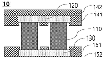
도 1은 본 발명의 일 실시예의 열전소자의 단면도,
도 2는 본 발명의 일 실시예의 전극의 평면도,
도 3은 본 발명의 일 실시예의 전극의 선폭에 따른 최적화를 수행한 결과를 확인한 것,
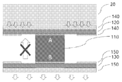
도 4는 본 발명의 일 실시예의 냉각시 열전도의 방향을 도시한 것,
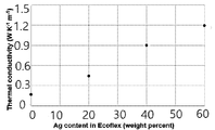
도 5는 본 발명의 일 실시예의 탄성복합체에서 탄성중합체 및 금속 나노물질의 혼합비에 따른 열전도도의 효과를 확인한 것,
도 6은 본 발명의 일 실시예의 열전소자의 단면도,
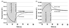
도 7은 본 발명의 일 실시예의 냉각 및 가열시에 인버스 모드 및 노멀 모드를 통하여 상온에 도달하는 시간을 비교한 것,
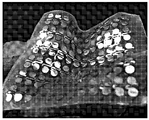
도 8은 본 발명의 일 실시예의 열전소자의 사진,
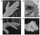
도 9는 본 발명의 일 실시예의 열전소자의 신축성을 나타낸 사진,
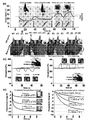
도 10은 본 발명의 일 실시예의 열전소자를 포함하는 웨어러블 장치의 실험결과를 나타낸 것,
도 11은 본 발명의 일 실시예의 열전소자 제조방법에 따른 제조형태를 제조단계별로 도시화한 것.
이하, 도면을 참조하여 본 발명의 구체적인 실시예를 설명한다. 그러나 이는 예시적 실시예에 불과하며 본 발명은 이에 한정되지 않는다.
본 발명을 설명함에 있어서, 본 발명과 관련된 공지기술에 대한 구체적인 설명이 본 발명의 요지를 불필요하게 흐릴 수 있다고 판단되는 경우에는 그 상세한 설명을 생략하기로 한다. 그리고, 후술되는 용어들은 본 발명에서의 기능을 고려하여 정의된 용어들로서 이는 사용자, 운용자의 의도 또는 관례 등에 따라 달라질 수 있다. 그러므로 그 정의는 본 명세서 전반에 걸친 내용을 토대로 내려져야 할 것이다.
본 발명의 기술적 사상은 청구범위에 의해 결정되며, 이하 실시예는 진보적인 본 발명의 기술적 사상을 본 발명이 속하는 기술분야에서 통상의 지식을 가진자에게 효율적으로 설명하기 위한 일 수단일 뿐이다.
또한 첨부된 도면은 본 발명의 기술적 사상을 보다 구체적으로 설명하기 위해 도시한 일 예에 불과하므로 본 발명의 기술적 사상이 첨부된 도면의 형태에 한정되는 것은 아니다.
덧붙여, 명세서 전체에서, 어떤 부분이 다른 부분과 '연결'되어 있다고 할 때, 이는 '직접적으로 연결'되어 있는 경우뿐만 아니라, 그 중간에 다른 소자 또는 제어부를 사이에 두고 '간접적으로 연결'되어 있는 경우도 포함한다. 또한, 기계적 또는 전기적으로 연결되어 있는 경우도 포함한다. 또한, 어떤 구성요소를 '포함'한다는 것은, 특별히 반대되는 기재가 없는 한 다른 구성요소를 제외하는 것이 아니라 다른 구성요소를 더 포함할 수 있다는 것을 의미한다.
본 발명의 일 측면에 따르면, 열전소자가 제공될 수 있다. 본 발명의 일 측면에 따른 일 실시예의 열전소자는 도 1에 도시하였다. 본 발명의 일 실시예에 따른 열전소자(10)는 열전물질(110); 상기 열전물질(110)의 양측에 각각 연결되는 한 쌍의 전극(120, 130); 상기 한 쌍의 전극(120, 130)의 적어도 일부에 각각 접하도록 위치되는 한 쌍의 탄성복합체(140, 150)를 포함할 수 있다.
상기 열전물질(110)은 p형 또는 n형 반도체를 포함할 수 있다. 상세하게는, 상기 열전물질(110)은 p형 반도체를 포함하는 p형 열전물질 또는 n형 반도체를 포함하는 n형 열전물질일 수 있다. 상기 p형 열전물질 및 상기 n형 열전물질은 후술할 전극(120,130)에 의하여 전기적으로 연결될 수 있다. 상기 열전물질(110)은 실리콘(Si), 알루미늄(Al), 칼슘(Ca), 나트륨(Na), 게르마늄(Ge), 철(Fe), 납(Pb), 안티몬(Sb), 텔루륨(Te), 비스무스(Bi), 코발트(Co), 세륨(Ce), 주석(Sn), 니켈(Ni), 구리(Cu), 나트륨(Na), 칼륨(K), 백금(Pt), 루테늄(Ru), 로듐(Rh), 금(Au), 텅스텐(W), 팔라듐(Pd), 티타늄(Ti), 탄탈륨(Ta), 몰리브덴(Mo), 하프늄(Hf), 란타늄(La), 이리듐(Ir), 은(Ag), 붕소(B), 갈륨(Ga), 셀레늄(Se) 및 인듐(In)으로 이루어진 군에서 선택되는 적어도 하나의 화합물을 포함하여 구성될 수 있으나 이에 한정되는 것은 아니다. 상세하게는, 상기 열전물질(110)이 n형 열전물질인 경우에는 셀레늄(Se), 니켈(Ni), 알루미늄(Al), 구리(Cu), 은(Ag), 납(Pb), 붕소(B), 갈륨(Ga), 텔루륨(Te), 비스무스(Bi) 및 인듐(In)으로 이루어진 군에서 선택되는 적어도 하나의 화합물을 포함하여 구성될 수 있으며, p형 열전물질인 경우에는 안티몬(Sb), 니켈(Ni), 알루미늄(Al), 구리(Cu), 은(Ag), 납(Pb), 붕소(B), 갈륨(Ga), 텔루륨(Te), 비스무스(Bi) 및 인듐(In)으로 이루어진 군에서 선택되는 적어도 하나의 화합물을 포함하여 구성될 수 있다. 상기 열전물질(110)은 핀 또는 기둥형상일 수 있다. 상기 기둥형상은 원기둥 또는 다각기둥일 수 있다. 본 실시예에서는 사각 기둥 형상인 것으로 설명한다. 상기 열전물질(110)의 직경은 한정되지 않으나, 마이크로미터 단위일 수 있다.
상기 한 쌍의 전극(120, 130)은 전기전도도가 우수하면서도 변형 가능한 무기물을 포함하여 형성될 수 있다. 이 때, '변형 가능'하다는 것은 유연하게 휘거나 구부러질 수 있는 것을 의미한다. 상기 무기물로는 예를 들면, 니켈(Ni), 알루미늄(Al), 구리(Cu), 루테늄(Ru), 로듐(Rh), 금(Au), 텅스텐(W), 코발트(Co), 팔라듐(Pd), 티타늄(Ti), 탄탈륨(Ta), 철(Fe), 몰리브덴(Mo), 하프늄(Hf), 란타늄(La), 이리듐(Ir) 및 은(Ag)으로 이루어진 군에서 선택되는 적어도 하나를 포함하여 형성될 수 있으나 이에 한정되는 것은 아니다. 본 실시예에서는 상기 한 쌍의 전극(120,130)은 구리 전극인 것으로 설명한다.
상기 한 쌍의 전극(120,130)은 전술한 상기 열전물질(110)의 일측 및 타측에 각각 연결될 수 있다. 이 때, '연결'의 의미는 전기적으로 연결되는 것이라면 한정되지 않으며, 예를 들면, 전도성 접착제 또는 납땜을 통하여 상기 한 쌍의 전극(120,130)과 상기 열전물질(110)의 연결이 이루어질 수 있다. 이하 본 실시예를 설명함에 있어서, 상기 한 쌍의 전극(120,130) 중 상기 열전물질(110)의 일측에 연결되는 전극을 제 1전극(120)으로, 상기 열전물질(110)의 타측에 연결되는 전극을 제 2전극으로 하기로 한다. n형 열전물질 및 p형 열젼물질은 상기 제 1전극(120) 및 상기 제 2전극(130)을 통해 연결될 수 있다. 상세하게는, n형 열전물질 및 p형 열전물질의 일측은 각각 상기 제 1전극(120)에 접하도록 연결되고, 상기 n형 열전물질 및 p형 열전물질의 타측은 각각 상기 제 2전극(130)에 접하도록 연결됨으로써, 상기 n형 열전물질과 p형 열전물질이 서로 전기적으로 연결될 수 있다. 이를 통하여, 상기 제 1전극(120) 및 상기 제 2전극(130)은 각각의 일측면이 서로 대향되도록 배치될 수 있다. 이후 본 실시예를 설명함에 있어서, 서로 대향되도록 배치되는 상기 제 1전극(120) 및 상기 제2전극(130)의 각 일측면을 각 대향면으로 기재하기로 한다. 상기 열전물질(110)은 상기 제 1전극(120) 및 상기 제 2전극(130)의 대향면에 접할 수 있다.
본 발명의 일 실시예에 따른 열전소자는 열전물질(110)의 연결에 사용되는 전극이 후술할 특정 구조를 갖도록 하여 웨어러블 목적에 부합하는 인장을 구현할 수 있다. 상기 제 1전극 및 상기 제 2전극(130)은 서로 대응되는 형상으로 형성될 수 있다. 상기 제 1전극(120) 및 상기 제 2전극(130)의 형상의 일 예시를 도 2에 도시하였다. 도 2를 참조하면, 상기 제 1전극(120) 및 상기 제 2전극(130)은 한 쌍의 열전물질접촉부(121); 및 연결부(122)를 포함할 수 있다.
상기 열전물질접촉부(121)는 상기 열전물질(110)과 연결되기 위한 부분으로, 이를 통하여 본 실시예의 전극(120,130)의 적어도 일부는 상기 열전물질(110)의 양측과 각각 전기적으로 연결될 수 있다. 상기 열전물질(110)은 상기 열전물질접촉부(121)와 접하도록 위치되어 상기 제 1전극(120) 또는 상기 제 2전극(130)과 전기적으로 연결될 수 있으며, 이 때 상기 열전물질접촉부(121)는 각각 다른 열전물질(110)과 접촉할 수 있다. 상세하게는, 상기 한 쌍의 열전물질접촉부(121) 중 하나는 제 1열전물질과 접촉하고, 상기 한 쌍의 열전물질접촉부(121) 중 다른 하나는 제 2열전물질과 접촉할 수 있다. 이 때, 상기 제 1열전물질은 n형 열전물질이고, 상기 제 2열전물질은 p형 열전물질일 수 있다.
상기 열전물질접촉부(121)의 형상은 특별히 한정되지 않으며, 평탄면을 포함하여 형성될 수 있다. 제조되는 본 발명의 일 실시예의 열전소자를 여러 방향으로 구부릴 때 받는 기계적 저항을 저감시키기 위하여는, 각형 또는 모서리를 포함하지 않는 곡선형의 평탄면을 갖도록 형성될 수 있다. 본 실시예에서는 평탄면이 원형상으로 형성되는 것으로 설명한다. 상기 열전물질접촉부(121)는 상기 열전물질(110)이 전극과 접하는 면과 같거나 또는 그보다 큰 면적을 갖도록 형성될 수 있다. 본 실시예에서는, 상기 열전물질(110)이 사각 기둥 형상이고, 사각형상으로 된 일측면이 상기 열전물질접촉부(121)와 접하여 연결되며, 상기 열전물질접촉부(121)는 상기 사각형상을 내부에 포함할 수 있는 큰 원형상인 것으로 설명한다.
상기 한 쌍의 열전물질접촉부(121)는 상기 연결부(122)를 통하여 서로 연결될 수 있다. 상기 연결부(122)는 곡률을 가지도록 형성될 수 있다. 이 때, 상기 곡률은 상기 한 쌍의 열전물질접촉부(121)와 상기 연결부(122)가 놓이는 일 평면상에서 곡률을 가지도록 형성될 수 있다. 상세하게는, 도 2에 도시된 도면을 기준으로 가로방향을 X축, 세로방향을 Y축, 상기 가로방향 및 세로방향을 3차원적으로 수직으로 가로지르는 Z축으로 하여 방향성을 설명할 때, X축 및 Y축으로 이루어지는 평면상에서 곡률을 가지도록 형성될 수 있다. 상세하게는, 상기 연결부(122)는 Z축이 아닌 X축 또는 Y축상에서 곡률을 나타내도록 형성될 수 있다. 또는, Z축이 아닌 X축 및 Y축에서 곡률을 나타내도록 형성될 수도 있다. 본 실시예에서는 상기 연결부(122)가 Y축 방향으로 곡률을 가지는 S자형으로 형성되는 것으로 설명한다. 본 발명의 일 실시예는 전술한 바와 같이 곡률을 가지는 연결부(122)를 통하여 상기 열전물질접촉부(121)를 유연하게 연결할 수 있으며, 이를 통하여 상기 열전물질접촉부(121)에 접하는 열전물질(110)을 3차원적으로 유연하고 신축성있게 움직이도록 할 수 있다. 예를 들면, Y축방향으로 인장력이 가해지는 경우, 상기 연결부(122)의 곡률이 저감되면서 상기 전극(120,130)이 탄력적으로 인장될 수 있다.
열전소자 자체는 전자(electron)와 정공(hole)의 전기적 분포에 따라 동작하므로, 전기적 저항은 열전소자에 있어 굉장히 중요한 요소로 작용하게 된다. 인장에 용이하도록 구리 전극을 제조하는 경우, 전극의 선폭이 얇을수록 기계적인 응력에는 강한 특성을 갖게 되므로, 전극의 설계시 두께는 고정시키는 대신 선폭을 변수로 두어, 50% 인장시 전극에 가해지는 응력과 전기적 저항의 곱을 시뮬레이션을 통해 계산하여 최적화를 수행하고, 그 결과를 도 3에 나타냈다. 이 때, 선폭은 도 2에 도시한 연결부(122)의 선폭(W)을 의미한다. 도 3을 보면, 전극의 선폭이 600㎛ 이상인 범위에서 응력과 저항을 곱한 값의 기울기가 원만해지는 것을 확인할 수 있다. 전술한 바와 같이 전극의 선폭이 너무 두꺼워지게 되면 전극의 기계적 강도가 저하되는 문제가 발생하게 되므로, 최적화를 위한 선폭을 600㎛을 기준으로 하여, 열전소자의 웨어러블 성능 및 기계적 강도를 고려한, 전기전도성을 유지하며 우수한 신축성을 나타낼 수 있는 전극 성능의 최적화를 위한 상기 연결부(122)의 선폭은 500 내지 700㎛으로 형성될 수 있다.
상기 제 1전극(120) 및 상기 제 2전극(130)은 상기 한 쌍의 탄성복합체(140, 150)에 각각 접하도록 배치될 수 있다. 이 때, 각 전극(120,130)은 각 탄성복합체(140,150)에 적어도 부분적으로 인입 배치될 수 있다. 이를 통하여, 상기 탄성복합체는 상기 제 1전극(120) 및 상기 제 2전극(130)의 대향면인 일측면 및 타측면에 접하도록 배치될 수 있다.
상기 탄성복합체(140,150)는 유연성 및 탄력성을 가지며, 탄성중합체 및 금속 나노물질을 포함할 수 있다. 상기 탄성중합체는 탄력성 및 유연성을 갖는 재질이면 특별히 한정되지는 않으며, 예를 들면, 실리콘 폴리머 계열일 수 있다. 상기 금속 나노물질은 나노 사이즈의 크기를 갖는 무기물질이면 특별히 한정되지는 않으며, 예를 들면, 나노 은 입자일 수 있다. 탄성중합체 및 금속 나노물질을 포함하는 합성물질인 탄성복합체(140,150)는 전기전도도는 띄지 않으나 열물성을 우수하게 개선시킬 수 있다. 상세하게는, 상기 탄성복합체(140,150)는 자유롭게 형상을 가공할 수 있는 탄성중합체에, 전도성이 우수한 금속 나노물질을 혼합하여 제조될 수 있으며, 본 실시예의 열전소자는 상기 탄성복합체(140,150)를 구리 전극(120,130)에 얇게 도포함으로써 열전소자의 열전도도를 개선할 수 있다. 이를 열전달을 촉진시키고자 하는 표면에 적용할 수 있으며, 시스템 상에서 생성된 열이 내부에 축적되어 냉각시의 열전소자 성능을 저하시키는 것을 방지할 수 있다. 또한, 상기 탄성복합체(140,150)는 열전도도가 우수하게 되므로, 이를 적용한 본 발명의 일 실시예의 열전소자는 냉방 또는 가열 시 교환되는 열량이 높아지게 되어 열전소자의 효율이 향상될 수 있다. 본 실시예의 열전소자를 인체에 부착하여 냉각 수행시, 상기 탄성복합체(140,150) 적용에 따른 열전도의 방향 및 방열 개선을 도 4에 나타냈다. 도 4에서, 열전도의 방향을 화살표로 나타내었으며, 인체(20)에 접하지 않는 쪽으로의 열전도는 방열을 의미한다. 또한, 열전물질(110)의 일측(A)은 냉각부, 타측(B)은 가열부를 포함한다. 도 4를 보면, 열전물질(110)을 사이에 두고 대향되게 배치되는 전극(120,130) 및 탄성복합체(140,150) 사이에 공기층이 존재하게 되며, 인체(20)에 접하지 않는 다른 방향으로부터의 열전도는 차단될 수 있다.
상기 탄성복합체(140,150)에 있어서, 탄성중합체 및 금속 나노물질의 혼합중량비에 따른 열전도도의 효과를 확인한 결과는 도 5에 나타냈다. 탄성복합체(140,150) 총 100wt%를 기준으로, 포함하는 금속 나노물질의 함량이 60wt%를 초과하게 되는 경우에는, 금속 나노물질의 분산성이 저하되어 입자간 뭉침과 같은 문제가 발생하였다. 도 5를 참조하면, 탄성복합체(140,150) 총 100wt%를 기준으로, 금속 나노물질의 함량이 0wt%인 경우와 60wt%인 경우를 비교하면, 60wt%으로 금속 나노물질을 포함하는 탄성복합체(140,150)의 열전도도가 6배 이상 우수한 것으로 나타났다. 이에 상기 탄성복합체(140,150)에 있어서, 탄성중합체 및 금속 나노물질의 혼합비는 탄성복합체(140,150) 총 100wt%를 기준으로, 20 내지 60wt% 함량으로 금속 나노물질을 포함하도록 할 수 있다. 본 실시예에서는 60wt% 함량으로 금속 나노물질을 포함하는 탄성복합체(140,150)를 이용한 것으로 설명한다.
도 6에 본 발명의 다른 실시예에 따른 열전소자의 단면도를 도시하였다. 도 4를 보면, 상기 한 쌍의 탄성복합체는 각각 제 1 탄성복합체(141, 151) 및 제 2 탄성복합체(142,152)를 포함할 수 있다. 후술할 본 발명의 제조방법의 일 실시예에 따르면, 상기 탄성복합체는 서로 구별되는 두 단계에서 각각 제조될 수 있다. 이에 본 실시예의 설명에 있어서도 탄성복합체를 구별하여, 한쌍의 제 1 탄성복합체(141,151) 및 한쌍의 제 2 탄성복합체(142,152)를 포함하는 것으로 설명하기로 하나, 이러한 구분은 일 실시예를 설명함에 있어서의 편의를 위한 것일 뿐이며, 이러한 구분에 의하여 상기 제 1 탄성복합체(141,151) 및 상기 제 2 탄성복합체(142,152) 사이에 유념할만한 다른 차이가 새로 발생하는 것은 아니다.
상기 한쌍의 제 1 탄성복합체(141,151)는, 상기 제 1전극(120) 및 상기 제 2전극(130)의 각 대향면의 적어도 일부에 각각 접하도록 위치될 수 있다. 상기 한쌍의 제 2 탄성복합체(142,152)는, 상기 제 1전극(120) 및 상기 제 2전극(130)의 타측면의 적어도 일부에 각각 접하도록 위치될 수 있다. 이 때, 상기 제 1 탄성복합체(141,151)는 상기 전극(120,130)의 대향면의 적어도 일부와 접하도록 위치될 수 있다. 상세하게는, 상기 전극(120,130)에 포함되는 상기 연결부(122)의 대향면인 일측면의 적어도 일부와 접하도록 위치될 수 있다. 또한, 상기 제 2 탄성복합체(142,152)는 상기 전극(120,130)의 타측면의 전체와 접하도록 위치될 수 있다. 이러한 배치를 통하여, 상기 연결부(122)는 적어도 부분적으로 상기 제 1 탄성복합체(141,151) 및 제 2 탄성복합체(142,152)에 의하여 모두 접하게 되어, 기계적 물성의 저하를 방지하고 내구성을 향상시킬 수 있다. 상기 제 1 탄성복합체(141,152) 및 상기 제 2 탄성복합체(142,152)는 상기 제 1전극(120) 또는 상기 제 2전극(130)을 사이에 두고 위치되게 되며, 각각 상기 전극(120,130)에 접하지 않으면서 서로 대향되는 부분이 서로 직접적으로 접촉될 수 있다. 이러한 구성을 통하여, 본 실시예의 전극(120,130)은 상기 제 1 탄성복합체(141,151) 및 상기 제 2 탄성복합체(142,152)에 모두 접하여, 탄성복합체 내에 적어도 부분적으로 인입 배치될 수 있다.
본 발명의 일 실시예의 열전소자는 전류의 방향에 따라 냉각 및 가열을 모두 수행할 수 있다. 이를 통하여, 냉각 또는 가열이 종료된 후 전류의 방향을 바꿔주게 되면 자연대류에 의존하는 것보다 빠른 시간 안에 상온에 도달할 수 있다. 본 실시예에서 이를 설명함에 있어서, 전류의 방향을 바꾸어 수행되는 이러한 기능을 인버스 모드(inverse mode)라 하고, 자연대류에 의존하는 것을 노멀 모드(normal mode)로 하기로 한다. 냉각 및 가열을 각각 인버스 모드 및 노멀 모드로 수행하고 변화된 온도에서 상온에 다시 도달하기까지 시간을 측정하여 비교한 결과를 도 7에 나타냈다. 도 7에서, 냉각 수행후 상온에 도달하는 것을 비교한 결과는 (A)에, 가열 수행후 상온에 도달하는 것을 비교한 결과는 (B)에 나타냈다. 도 7을 보면, 냉각 및 가열 모두 인버스 모드를 통하여 상온에 도달하는 시간이 노멀 모드에 비교하여 7 내지 8배 빠른 것을 확인할 수 있다.
본 발명의 일 실시예에 따른, 인장이 용이하게 설계된 전극(120,130)이 복수개 배치되고 탄성복합체(140,150)가 적용된 열전소자의 사진을 도 8에 나타냈다. 본 발명의 일 실시예에 따른 열전소자는, 전술한 열전도성 탄성복합체(140,150)를 통해 신축성을 나타내면서도 냉각 시 소자의 성능을 개선하고, 인체에 접촉되는 경우에는 인체와의 열교환을 향상시킬 수 있다. 본 발명의 일 실시예에 따른 열전소자는 거대한 장치를 필요로 하지 않아 컴팩트한 사이즈의 시스템으로 형성될 수 있으며, 다양한 형상에 맞춘 유연성 및 탄력성을 필요로 하며, 대형 시스템의 적용이 어려운 웨어러블 전자 장치에 적용하기 적합하다. 또한, 굴곡진 형태에도 부착 가능하므로 다양한 형상에 부착하기 위한 열전소자 시스템으로 적용할 수 있다. 본 발명의 일 실시예의 열전소자가 적용된 웨어러블 전자 장치는 냉각 및 가열이 모두 수행가능하므로, 냉각 또는 가열로 가동 후 상온으로 빠르게 돌아갈 수 있어, 착용자가 원하는 열감을 빠르게 제공할 수 있다.
본 발명의 다른 측면에 따르면, 전술한 열전소자를 포함하는 웨어러블 장치가 제공될 수 있다. 본 발명에 따른 웨어러블 장치는 본 발명에 따른 열전소자와, 열전소자가 부착되고 인체와 접하도록 형성되는 착용부를 포함할 수 있다. 또한, 웨어러블 장치의 착용부는 착용자가 착용할 수 있는 다양한 의복의 형태로 나타날 수 있으나, 바람직하게는 착용자의 손에 착용될 수 있는 장갑일 수 있다. 장갑은 착용자의 손가락을 수용하는 적어도 하나의 수지부를 포함할 수 있으며, 열전소자는 수지부의 일단에 부착될 수 있다. 한편, 본 발명에 따른 열전소자는 굴곡진 형태에도 부착 가능한 것으로 인체의 피부에 밀착하여 피부의 움직임에 따라 신축이 가능한 바, 열전소자는 착용자의 손바닥과 접촉하는 부분에 부착될 수도 있으며, 이는 착용자가 가상의 열감 환경을 경험할 수 있는 착용부의 어느 부분에라도 적용이 가능하다. 본 발명의 일실시예의 열전소자가 인체에 부착되어 신축 가능한 구조임을 도 9에 나타냈다.
한편, 본 발명의 일실시예의 웨어러블 장치에 대하여 가상현실 상에서 특정 온도를 가지는 물체와 접촉하였을 때 실제와 같은 열감 환경을 제공할 수 있다. 이는 가상현실 상에 존재하는 온도를 가지는 물체와 접촉 시에 해당 물체가 가지는 열전도계수를 적용 및 알고리즘화 함으로써, 가상현실 상에 서로 다른 물체에 접촉하는 경우 열전소자의 냉각 및 가열되는 속도 및 정도를 조절할 수 있다. 본 발명의 일실시예의 웨어러블 장치가 이러한 냉각 및 가열을 수행할 때, 전술한 바와 같은 인버스 모드 및 노멀 모드를 통하여 열교환을 수행할 수 있다. 본 발명의 일실시예의 열전소자가 포함된 웨어러블 장치를 착용하고 가상현실 상의 물체와 접촉하였을 때 온도 변화에 대한 실험예를 도 10에 나타냈다.
본 발명의 다른 측면에 따르면, 열전소자의 제조방법이 제공될 수 있다. 본 발명의 일 측면에 따른 일 실시예의 열전소자 제조방법은 전극 소재를 준비하는 제 1단계(S1); 열전도성 탄성복합체의 일측면상에 상기 전극 소재를 두고 레이저로 가공하여 전극을 형성하는 제 2 단계(S2); 상기 제 2단계에서 제조된 구조 위에 상기 열전도성 탄성복합체를 도포 및 가열하는 제 3단계(S3); 상기 제 3단계에서 도포된 탄성복합체의 적어도 일부를 제거하여 상기 전극을 노출시켜, 전극의 일부가 노출된 제 1 구조체를 제조하는 제 4단계(S4); 상기 제 1단계에서 상기 제 4단계까지를 반복하여, 제 2 구조체를 준비하는 제 5단계(S5); 및 열전 물질을 사이에 두고 상기 제 1 구조체 및 상기 제 2구조체를 연결시키는 제 6단계(S6)를 포함할 수 있다. 본 발명의 일 실시예의 열전소자 제조방법에 따른 제조형태를 제조단계별로 도시화하여 도 11에 나타냈다.
먼저, 제 1단계(S1)는 전극 소재를 유연한 중합체 용액으로 코팅하여 수행될 수 있다. 상기 중합체는, 예를 들면, 폴리이미드일 수 있으나 이에 한정되는 것은 아니다. 상기 코팅은 중합체 용액을 전극 소재 호일에 도포한 후 가열하여 수행될 수 있다. 예를 들어, 상기 전극 소재로 구리 호일을 적용하고 상기 중합체 용액으로 폴리이미드 용액을 이용한 경우, 폴리이미드 용액을 구리 호일에 도포하고 120 내지 150℃, 바람직하게는 140℃에서 3 내지 5분, 바람직하게는 4분동안 대기 조건 가열하고, 230 내지 270℃, 바람직하게는 250℃에서 질소 환경하에 40 내지 80분, 바람직하게는 1시간동안 가열하여 본 단계가 수행될 수 있다.
다음으로, 상기 제 2단계(S2)에서 상기 전극은 전술한 특정 구조를 갖도록 형성될 수 있다. 상세하게는, 한 쌍의 열전물질접촉부 및 연결부를 포함하도록 형성될 수 있으며, 이 때, 상기 연결부는 상기 한 쌍의 열전물질접촉부를 연결하기 위한 것으로, 평면상에서 곡률을 가지도록 형성될 수 있다. 상기 전극은 이전 단계(S1)에서 준비된 전극 소재를 열전도성 탄성복합체 위에 놓고 가공하여 수행될 수 있다. 상기 가공방법은 특별히 한정되지는 않으나, 예를 들면 레이저 가공일 수 있다. 상기 열전도성 탄성복합체는 탄성중합체 및 금속 나노 물질을 혼합하여 제조될 수 있다.
다음으로, 이전 단계(S2)에서 형성된 구조에서, 전극이 노출되는 일측으로 열전도성 탄성복합체의 도포가 수행되는 제 3단계(S3)가 수행될 수 있다. 상기 제 3단계(S3)에서 도포 후 가열이 수행되며, 이 때 가열 조건은 50 내지 70℃, 바람직하게는 60℃ 온도에서 5 내지 20분, 바람직하게는 10분동안 수행될 수 있다.
다음으로, 상기 제 4단계(S4)에서, 상기 열전물질접촉부의 적어도 일부가 노출될 수 있다. 본 단계(S4)는 레이저로 탄성중합체에 구멍을 뚫어 전극을 노출시키도록 하여 수행될 수 있다. 이 때, 노출되는 전극의 적어도 일부분은 전술한 열전물질접촉부의 적어도 일부를 포함할 수 있다.
다음으로, 전술한 상기 제 1단계 내지 상기 제 4단계를 다시 한번 반복하는 제 5단계(S5)가 수행될 수 있다. 본 단계(S5)에서 이전에 제조된 것과 동일한 구조체를 한 쌍으로 준비할 수 있으며, 이후 제 6단계(S6)에서, 상기 열전물질 및 상기 전극 사이가 납땜, 가열 및 가압을 통해 연결되어 본 발명의 일 실시예의 열전소자가 제조될 수 있다.
[부호의 설명]
10 : 열전소자
110 : 열전물질
120, 130 : 전극
121 : 열전물질접촉부
122 : 연결부
140, 150 : 탄성복합체
20 : 인체
Claims (19)
- 열전물질;변형 가능하며, 상기 열전물질의 양측에 각각 전기적으로 연결되고, 일측면이 서로 대향되는 제 1전극 및 제 2전극;상기 제 1전극 및 상기 제 2전극의 각 일측면의 적어도 일부에 각각 접하도록 위치되는 한 쌍의 제 1 탄성복합체;상기 제 1전극 및 상기 제 2전극의 각 타측면에 각각 접하도록 위치되는 한 쌍의 제 2 탄성복합체;를 포함하는, 신축성 및 유연성을 가지는 열전소자.
- 청구항 1에 있어서,상기 제 1 탄성복합체 및 상기 제 2 탄성복합체는 탄성중합체 및 금속 나노물질을 포함하는, 신축성 및 유연성을 가지는 열전소자.
- 청구항 2에 있어서,상기 제 1 탄성복합체 및 상기 제 2 탄성복합체는 각 탄성복합체 총 100wt%에 있어서, 상기 금속 나노물질을 20 내지 60wt%함량으로 포함하는, 신축성 및 유연성을 가지는 열전소자.
- 청구항 1에 있어서,상기 제 1전극 및 상기 제 2전극은 구리 전극인, 신축성 및 유연성을 가지는 열전소자.
- 청구항 1에 있어서,상기 제 1전극 및 상기 제 2전극은 원형상으로 형성되는 한 쌍의 열전물질접촉부; 및평면상에서 곡률을 가지도록 형성되며, 상기 한 쌍의 열전물질접촉부를 서로 연결하는 연결부;를 포함하는, 신축성 및 유연성을 가지는 열전소자.
- 청구항 1에 있어서,상기 제 1전극 및 상기 제 2전극은 원형상으로 형성되는 한 쌍의 열전물질접촉부; 및평면상에서 곡률을 가지도록 형성되며, 상기 한 쌍의 열전물질접촉부를 서로 연결하는 연결부;를 포함하고,상기 열전물질은 상기 열전물질접촉부와 접하도록 위치되어 상기 제 1전극 또는 상기 제 2전극과 전기적으로 연결되는, 신축성 및 유연성을 가지는 열전소자.
- 청구항 1에 있어서,상기 제 1전극 및 상기 제 2전극은 원형상으로 형성되는 한 쌍의 열전물질접촉부; 및평면상에서 곡률을 가지도록 형성되며, 상기 한 쌍의 열전물질접촉부를 서로 연결하는 연결부;를 포함하고,상기 제 1 탄성복합체는 상기 연결부의 적어도 일부의 일측면과 접하도록 위치되는, 신축성 및 유연성을 가지는 열전소자.
- 청구항 5에 있어서,상기 연결부는 500 내지 700㎛의 폭으로 형성되는, 신축성 및 유연성을 가지는 열전소자.
- 청구항 1에 있어서,상기 제 1전극 또는 상기 제 2전극을 사이에 두고 위치되는 상기 제 1 탄성복합체 및 상기 제 2 탄성복합체의 적어도 일부는 서로 직접적으로 접촉되는, 신축성 및 유연성을 가지는 열전소자.
- 열전물질;유연성 및 탄력성을 가지는 적어도 한 쌍의 탄성복합체; 및변형 가능하고, 상기 탄성복합체에 적어도 부분적으로 인입 배치되되, 적어도 일부는 상기 열전물질의 양측과 각각 전기적으로 연결되는 제 1전극 및 제 2전극;을 포함하는, 신축성 및 유연성을 가지는 열전소자.
- 청구항 1 내지 10 중 어느 한 항의 열전소자; 및상기 열전소자가 부착되고 인체와 접하도록 형성되는 착용부;를 포함하는 웨어러블 장치.
- 청구항 11에 있어서,상기 착용부는착용자의 손가락을 수용하는 적어도 하나의 수지부를 포함하는 장갑인 웨어러블 장치.
- 청구항 12에 있어서,상기 열전소자는 상기 적어도 하나의 수지부의 일단에 부착되는 웨어러블 장치.
- 전극 소재를 준비하는 제 1단계;열전도성 탄성복합체의 일측면상에 상기 전극 소재를 두고 레이저로 가공하여 전극을 형성하는 제 2 단계;상기 제 2단계에서 제조된 구조 위에 상기 열전도성 탄성복합체를 도포 및 가열하는 제 3단계;상기 제 3단계에서 도포된 탄성복합체의 적어도 일부를 제거하여 상기 전극을 노출시켜, 전극의 일부가 노출된 제 1 구조체를 제조하는 제 4단계;상기 제 1단계에서 상기 제 4단계까지를 반복하여, 제 2 구조체를 준비하는 제 5단계; 및열전물질을 사이에 두고 상기 제 1 구조체 및 상기 제 2구조체를 연결시키는 제 6단계를 포함하는, 신축성 및 유연성을 가지는 열전소자의 제조방법.
- 청구항 14에 있어서,상기 제 1단계는 전극 소재를 폴리이미드 용액으로 코팅하여 수행되는, 신축성 및 유연성을 가지는 열전소자의 제조방법.
- 청구항 14에 있어서,상기 탄성복합체는 탄성중합체 및 금속 나노 물질을 혼합하여 제조되는, 신축성 및 유연성을 가지는 열전소자의 제조방법.
- 청구항 14에 있어서,상기 제 3단계의 가열은 50 내지 70℃ 온도에서 5 내지 20분동안 수행되는, 신축성 및 유연성을 가지는 열전소자의 제조방법.
- 청구항 14에 있어서,상기 전극은 원형상으로 형성되는 한 쌍의 열전물질접촉부; 및평면상에서 곡률을 가지도록 형성되며, 상기 한 쌍의 열전물질접촉부를 서로 연결하는 연결부;를 포함하고,상기 제 4단계에서 상기 열전물질접촉부의 적어도 일부가 노출되는, 신축성 및 유연성을 가지는 열전소자의 제조방법.
- 청구항 14에 있어서,상기 제 6단계는 상기 열전물질 및 상기 전극 사이는 납땜, 가열 및 가압하여 연결되는, 신축성 및 유연성을 가지는 열전소자의 제조방법.
Priority Applications (1)
| Application Number | Priority Date | Filing Date | Title |
|---|---|---|---|
| US17/341,344 US11839157B2 (en) | 2018-12-07 | 2021-06-07 | Bidirectional stretchable and flexible wearable thermoelectric module |
Applications Claiming Priority (2)
| Application Number | Priority Date | Filing Date | Title |
|---|---|---|---|
| KR1020180157129A KR102152642B1 (ko) | 2018-12-07 | 2018-12-07 | 냉각 및 가열이 가능한 신축성 유연 웨어러블 열전소자 |
| KR10-2018-0157129 | 2018-12-07 |
Related Child Applications (1)
| Application Number | Title | Priority Date | Filing Date |
|---|---|---|---|
| US17/341,344 Continuation US11839157B2 (en) | 2018-12-07 | 2021-06-07 | Bidirectional stretchable and flexible wearable thermoelectric module |
Publications (1)
| Publication Number | Publication Date |
|---|---|
| WO2020116803A1 true WO2020116803A1 (ko) | 2020-06-11 |
Family
ID=70974346
Family Applications (1)
| Application Number | Title | Priority Date | Filing Date |
|---|---|---|---|
| PCT/KR2019/015294 Ceased WO2020116803A1 (ko) | 2018-12-07 | 2019-11-12 | 냉각 및 가열이 가능한 신축성 유연 웨어러블 열전소자 |
Country Status (3)
| Country | Link |
|---|---|
| US (1) | US11839157B2 (ko) |
| KR (1) | KR102152642B1 (ko) |
| WO (1) | WO2020116803A1 (ko) |
Cited By (3)
| Publication number | Priority date | Publication date | Assignee | Title |
|---|---|---|---|---|
| CN113380941A (zh) * | 2021-06-07 | 2021-09-10 | 北京航空航天大学 | 一种可拉伸多孔结构的面外型热电器件 |
| WO2022164080A1 (ko) * | 2021-01-28 | 2022-08-04 | 주식회사 테그웨이 | 무릎 찜질기 |
| JP2023144709A (ja) * | 2022-03-28 | 2023-10-11 | 国立研究開発法人産業技術総合研究所 | 熱電変換モジュール |
Families Citing this family (6)
| Publication number | Priority date | Publication date | Assignee | Title |
|---|---|---|---|---|
| KR102819925B1 (ko) * | 2020-09-24 | 2025-06-11 | 삼성전자주식회사 | 연신 소자용 적층 구조체, 연신 소자 및 그 제조 방법, 표시 패널, 센서 및 전자 장치 |
| KR102852519B1 (ko) | 2021-04-15 | 2025-08-28 | 삼성전자주식회사 | 연신 소자, 표시 패널, 센서 및 전자 장치 |
| WO2023047407A1 (en) * | 2021-09-24 | 2023-03-30 | Pandiyarasan Veluswamy | Smart jacket for all weather conditions |
| KR102588746B1 (ko) * | 2021-12-21 | 2023-10-13 | 한국세라믹기술원 | 유연성 열전모듈 |
| WO2023138692A1 (en) * | 2022-01-22 | 2023-07-27 | Massachusetts Institute Of Technology | Bulk-material based flexible thermoelectric generators for heat concentration and dissipation |
| JP2024039242A (ja) * | 2022-09-09 | 2024-03-22 | 株式会社Kelk | 熱電モジュール |
Citations (5)
| Publication number | Priority date | Publication date | Assignee | Title |
|---|---|---|---|---|
| JP2004140064A (ja) * | 2002-10-16 | 2004-05-13 | Citizen Watch Co Ltd | 熱電素子およびその製造方法 |
| JP2006013434A (ja) * | 2004-05-21 | 2006-01-12 | Matsushita Electric Works Ltd | 熱電変換素子モジュールおよびその集合体並びにこれらの製造方法 |
| JP2007095897A (ja) * | 2005-09-28 | 2007-04-12 | Toshiba Corp | 半導体装置とその製造方法 |
| KR101221581B1 (ko) * | 2011-10-20 | 2013-01-14 | 한국기계연구원 | 그래핀을 포함하는 유연투명전극 기판의 제조방법 및 이에 따라 제조되는 유연투명전극 기판 |
| KR20150116187A (ko) * | 2014-04-07 | 2015-10-15 | 홍익대학교 산학협력단 | 신축성 열전모듈 |
Family Cites Families (9)
| Publication number | Priority date | Publication date | Assignee | Title |
|---|---|---|---|---|
| US20050193742A1 (en) * | 2004-02-10 | 2005-09-08 | Its Kool, Llc | Personal heat control devicee and method |
| US8222511B2 (en) * | 2006-08-03 | 2012-07-17 | Gentherm | Thermoelectric device |
| JP5979883B2 (ja) * | 2012-01-16 | 2016-08-31 | 株式会社Kelk | 熱電素子およびこれを備えた熱電モジュール |
| JP6542504B2 (ja) * | 2013-02-20 | 2019-07-10 | 日東電工株式会社 | フィルム状接着剤、フィルム状接着剤付きダイシングテープ、半導体装置の製造方法、及び半導体装置 |
| JP6278879B2 (ja) * | 2014-10-29 | 2018-02-14 | アイシン高丘株式会社 | 熱電モジュール |
| US10388847B2 (en) * | 2015-05-14 | 2019-08-20 | Nimbus Materials Inc. | Method of producing a flexible thermoelectric device to harvest energy for wearable applications |
| JP6390546B2 (ja) * | 2015-08-03 | 2018-09-19 | 日立化成株式会社 | 熱電変換モジュールおよびその製造方法 |
| KR101989908B1 (ko) | 2015-10-27 | 2019-06-17 | 주식회사 테그웨이 | 유연 열전소자 및 이의 제조방법 |
| KR20170056853A (ko) | 2015-11-16 | 2017-05-24 | 부산대학교 산학협력단 | 유연한 열전소자 및 그 제조방법 |
-
2018
- 2018-12-07 KR KR1020180157129A patent/KR102152642B1/ko active Active
-
2019
- 2019-11-12 WO PCT/KR2019/015294 patent/WO2020116803A1/ko not_active Ceased
-
2021
- 2021-06-07 US US17/341,344 patent/US11839157B2/en active Active
Patent Citations (5)
| Publication number | Priority date | Publication date | Assignee | Title |
|---|---|---|---|---|
| JP2004140064A (ja) * | 2002-10-16 | 2004-05-13 | Citizen Watch Co Ltd | 熱電素子およびその製造方法 |
| JP2006013434A (ja) * | 2004-05-21 | 2006-01-12 | Matsushita Electric Works Ltd | 熱電変換素子モジュールおよびその集合体並びにこれらの製造方法 |
| JP2007095897A (ja) * | 2005-09-28 | 2007-04-12 | Toshiba Corp | 半導体装置とその製造方法 |
| KR101221581B1 (ko) * | 2011-10-20 | 2013-01-14 | 한국기계연구원 | 그래핀을 포함하는 유연투명전극 기판의 제조방법 및 이에 따라 제조되는 유연투명전극 기판 |
| KR20150116187A (ko) * | 2014-04-07 | 2015-10-15 | 홍익대학교 산학협력단 | 신축성 열전모듈 |
Cited By (4)
| Publication number | Priority date | Publication date | Assignee | Title |
|---|---|---|---|---|
| WO2022164080A1 (ko) * | 2021-01-28 | 2022-08-04 | 주식회사 테그웨이 | 무릎 찜질기 |
| CN113380941A (zh) * | 2021-06-07 | 2021-09-10 | 北京航空航天大学 | 一种可拉伸多孔结构的面外型热电器件 |
| JP2023144709A (ja) * | 2022-03-28 | 2023-10-11 | 国立研究開発法人産業技術総合研究所 | 熱電変換モジュール |
| JP7790716B2 (ja) | 2022-03-28 | 2025-12-23 | 国立研究開発法人産業技術総合研究所 | 熱電変換モジュール |
Also Published As
| Publication number | Publication date |
|---|---|
| KR102152642B1 (ko) | 2020-09-08 |
| US11839157B2 (en) | 2023-12-05 |
| KR20200069735A (ko) | 2020-06-17 |
| US20210296554A1 (en) | 2021-09-23 |
Similar Documents
| Publication | Publication Date | Title |
|---|---|---|
| KR20200069735A (ko) | 냉각 및 가열이 가능한 신축성 유연 웨어러블 열전소자 | |
| CN114546101A (zh) | 触觉再现装置、显示面板和显示装置 | |
| WO2017150932A1 (ko) | 열전 소자 및 이의 제조방법 | |
| WO2019139394A1 (ko) | 전력 반도체 모듈 | |
| Rahimi et al. | A low-cost fabrication technique for direct sewing stretchable interconnetions for wearable electronics | |
| CN210783050U (zh) | 一种智能手套 | |
| US20240365668A1 (en) | Thermoelectric power generation device, thermoelectric power generation device component, and manufacturing method therefor | |
| CN111319317A (zh) | 一种包含液态金属的纺织材料及其制备方法 | |
| WO2021206276A1 (ko) | 열전 모듈 및 이를 포함하는 열전 장치 | |
| KR101958094B1 (ko) | 투명 전극 구조물의 형성 방법 | |
| WO2024101525A1 (ko) | 유연 열전소자 모듈 및 이의 제조방법 | |
| WO2017123057A1 (ko) | 열전 소자 | |
| CN211508939U (zh) | 一种柔性可穿戴温差发电器及其组合 | |
| US11024789B2 (en) | Flexible encapsulation of a flexible thin-film based thermoelectric device with sputter deposited layer of N-type and P-type thermoelectric legs | |
| CN210017992U (zh) | 一种手指弯曲识别手套 | |
| US20210249579A1 (en) | Flexible encapsulation of a flexible thin-film based thermoelectric device with sputter deposited layer of n-type and p-type thermoelectric legs | |
| CN211957508U (zh) | 一种防短路的薄膜开关结构 | |
| CN107437534A (zh) | 可拉伸电子系统 | |
| CN111262473A (zh) | 一种柔性可穿戴温差发电器及其组合 | |
| CN115452209B (zh) | 一种基于非对称热整流结构的柔性多模态触觉传感器 | |
| US20240397618A1 (en) | Pptc small planar smd temperature sensors and overcurrent devices | |
| CN109735241B (zh) | 一种异方性导电结构及其制作方法、显示装置 | |
| KR20230172134A (ko) | 열전 소자를 이용한 수중 웨어러블 에너지 수확 및 체온유지 장치 | |
| TW201003858A (en) | Single chip semiconductor coating structure and its precesses | |
| CN207719185U (zh) | 一种快速散热的半导体器件结构 |
Legal Events
| Date | Code | Title | Description |
|---|---|---|---|
| 121 | Ep: the epo has been informed by wipo that ep was designated in this application |
Ref document number: 19893925 Country of ref document: EP Kind code of ref document: A1 |
|
| NENP | Non-entry into the national phase |
Ref country code: DE |
|
| 122 | Ep: pct application non-entry in european phase |
Ref document number: 19893925 Country of ref document: EP Kind code of ref document: A1 |