WO2020116218A1 - 複列円すいころ軸受 - Google Patents
複列円すいころ軸受 Download PDFInfo
- Publication number
- WO2020116218A1 WO2020116218A1 PCT/JP2019/045891 JP2019045891W WO2020116218A1 WO 2020116218 A1 WO2020116218 A1 WO 2020116218A1 JP 2019045891 W JP2019045891 W JP 2019045891W WO 2020116218 A1 WO2020116218 A1 WO 2020116218A1
- Authority
- WO
- WIPO (PCT)
- Prior art keywords
- seal
- outer ring
- insulating coating
- tapered roller
- roller bearing
- Prior art date
- Legal status (The legal status is an assumption and is not a legal conclusion. Google has not performed a legal analysis and makes no representation as to the accuracy of the status listed.)
- Ceased
Links
Images







Classifications
-
- F—MECHANICAL ENGINEERING; LIGHTING; HEATING; WEAPONS; BLASTING
- F16—ENGINEERING ELEMENTS AND UNITS; GENERAL MEASURES FOR PRODUCING AND MAINTAINING EFFECTIVE FUNCTIONING OF MACHINES OR INSTALLATIONS; THERMAL INSULATION IN GENERAL
- F16C—SHAFTS; FLEXIBLE SHAFTS; ELEMENTS OR CRANKSHAFT MECHANISMS; ROTARY BODIES OTHER THAN GEARING ELEMENTS; BEARINGS
- F16C19/00—Bearings with rolling contact, for exclusively rotary movement
- F16C19/22—Bearings with rolling contact, for exclusively rotary movement with bearing rollers essentially of the same size in one or more circular rows, e.g. needle bearings
- F16C19/34—Bearings with rolling contact, for exclusively rotary movement with bearing rollers essentially of the same size in one or more circular rows, e.g. needle bearings for both radial and axial load
- F16C19/38—Bearings with rolling contact, for exclusively rotary movement with bearing rollers essentially of the same size in one or more circular rows, e.g. needle bearings for both radial and axial load with two or more rows of rollers
-
- F—MECHANICAL ENGINEERING; LIGHTING; HEATING; WEAPONS; BLASTING
- F16—ENGINEERING ELEMENTS AND UNITS; GENERAL MEASURES FOR PRODUCING AND MAINTAINING EFFECTIVE FUNCTIONING OF MACHINES OR INSTALLATIONS; THERMAL INSULATION IN GENERAL
- F16C—SHAFTS; FLEXIBLE SHAFTS; ELEMENTS OR CRANKSHAFT MECHANISMS; ROTARY BODIES OTHER THAN GEARING ELEMENTS; BEARINGS
- F16C33/00—Parts of bearings; Special methods for making bearings or parts thereof
- F16C33/30—Parts of ball or roller bearings
- F16C33/58—Raceways; Race rings
- F16C33/64—Special methods of manufacture
-
- F—MECHANICAL ENGINEERING; LIGHTING; HEATING; WEAPONS; BLASTING
- F16—ENGINEERING ELEMENTS AND UNITS; GENERAL MEASURES FOR PRODUCING AND MAINTAINING EFFECTIVE FUNCTIONING OF MACHINES OR INSTALLATIONS; THERMAL INSULATION IN GENERAL
- F16C—SHAFTS; FLEXIBLE SHAFTS; ELEMENTS OR CRANKSHAFT MECHANISMS; ROTARY BODIES OTHER THAN GEARING ELEMENTS; BEARINGS
- F16C33/00—Parts of bearings; Special methods for making bearings or parts thereof
- F16C33/72—Sealings
- F16C33/76—Sealings of ball or roller bearings
- F16C33/78—Sealings of ball or roller bearings with a diaphragm, disc, or ring, with or without resilient members
Definitions
- the present invention relates to a double row tapered roller bearing.
- an object of the present invention is to provide a double row tapered roller bearing capable of preventing electrolytic corrosion.
- the present invention has been made to solve the above-mentioned problems, and an inner ring having a raceway surface on the outer circumference, an outer ring having a raceway surface on the inner circumference, and a double-row cone that is interposed between the raceway surface of the inner ring and the raceway surface of the outer ring.
- the outer ring has a roller and a seal member that seals a bearing inner space between the inner ring and the outer ring on both sides in the axial direction, and the outer ring has a seal restricting surface that can come into axial contact with the end surface of the seal member. It is a double row tapered roller bearing in which an insulating coating is provided from the surface to the width surface.
- the insulating coating is provided from the outer peripheral surface of the outer ring to the width surface. As a result, it is possible to secure insulation and prevent electrolytic corrosion.
- an annular step portion 103 is provided on the inner peripheral edge of the width surface 101 of the outer ring 100, and the inner surface 104 of this step portion is used as a reference surface for film thickness measurement. Specifically, first, before forming the insulating coating, the width dimension A between the reference surface 104 and the width surface 102 on the side opposite to the reference surface is measured.
- the insulating coating 105 is formed, and then the width dimension B between the reference surface 104 and the surface of the insulating coating covering the width surface 102 on the anti-reference surface side is measured, and the insulation formed on the width surface 102 on the anti-reference surface side is measured.
- the stock removal of the coating 105 is determined.
- the insulating coating 105 that covers the width surface 102 on the side opposite to the reference surface is machined while the reference surface 104 is being applied to the backing plate, and then the width finish dimension that is the target dimension and the total width dimension C including the insulating coating of the outer ring 100 are machined. Therefore, the allowance for the other insulating film is determined.
- the opposite side width surface is processed so as to be within the allowable range of the width finishing dimension with the surface of the processed insulating coating 105 covering the width surface 102 as a reference.
- the seal regulation surface as a grinding surface.
- the seal control surface is a ground surface with high surface accuracy, the seal control surface can be used as a reference surface when measuring the film thickness. Further, this seal regulation surface is an existing surface existing near the mounting portion when the seal member is attached to the outer ring, and when using this seal regulation surface as the reference surface, it is not necessary to newly provide a reference surface. Therefore, the film thickness can be accurately measured even when the radial dimension of the width surface of the outer ring is small.
- the seal control surface is a surface formed by cutting hardened steel, the surface has high surface accuracy, so the seal control surface can be used as a reference surface when measuring the film thickness. Therefore, the same effect as the above can be obtained.
- An outer ring is provided between the seal fitting surface that fits the outer peripheral surface of the seal member and the seal fitting surface and the raceway surface, and engages with a bead provided on the outer peripheral surface of the seal member to seal the seal member.
- the surface roughness of the seal regulating surface may be smaller than the surface roughness of the bead groove.
- the seal regulation surface has high surface accuracy, the seal regulation surface can be used as a reference surface when measuring the film thickness, and the same effect as above can be obtained.
- FIG. 12 is a cross-sectional view of a conventional rolling bearing (ball bearing) in which an insulating coating 300 is provided on the surface of the outer ring 200.
- the rolling bearing shown in FIG. 12 is a rolling bearing that supports the axle of a railway vehicle.
- the outer ring 200 is fixed by a housing 400 such as a shaft box so as not to move in the axial direction.
- a housing 400 such as a shaft box
- a potential difference of a certain level or more occurs between the housing 400 and the outer ring 200, a creeping discharge may occur along the end of the insulating coating 300, and electrolytic corrosion may occur.
- a chamfered portion 200a is formed at a corner of an outer ring 200, and the chamfered portion 200a is covered with an insulating coating 300.
- a configuration is proposed.
- the "creeping distance” in this specification means the minimum distance along the surface of the insulating coating (insulating member) sandwiched between the two conductors.
- the seal member comes into contact with the insulating coating 300 of the chamfered portion 200a when the seal member is mounted between the outer ring and the inner ring, so that insulation is achieved.
- the coating 300 may be damaged.
- the insulation coating in order to prevent the insulation coating from being damaged due to the mounting of such a seal member and to improve the insulation performance, it is inclined between the width surface of the outer ring and the inner peripheral surface inward in the axial direction with respect to the width surface of the outer ring.
- the first chamfered portion is provided, and the second chamfered portion, which is inclined axially inward with respect to the width surface of the outer ring, is provided on the inner side in the axial direction of the first chamfered portion. It is preferable that the insulating coating is provided on the first chamfered portion and the insulating coating is not provided on the surface of the second chamfered portion.
- the insulating coating of the first chamfered portion is damaged. It is possible to easily mount the seal member in the bearing without the need to do so. That is, when the seal member is mounted in the bearing, the seal member can be easily mounted in the bearing by bringing the outer peripheral surface of the seal member into contact with the second chamfered portion and guiding it. At this time, even if the sealing member comes into contact with the second chamfered portion, since the insulating coating is not provided on the second chamfered portion, there is no possibility of damaging the insulating coating due to the contact of the sealing member.
- the creepage distance becomes longer and the insulation performance is improved because the first chamfered portion is inclined axially inward of the end face of the outer ring.
- the longer creepage distance allows the housing that fixes the outer ring to be in contact with the end surface of the outer ring over a wide range (up to the position close to the inner peripheral surface of the outer ring). The axial movement of the can be reliably regulated for positioning.
- the double-row tapered roller bearing according to the present invention can be used, for example, as a bearing for a railroad vehicle axle that supports an axle of a railroad vehicle.
- the seal member can be brought into contact with the seal restricting surface of the outer ring to perform axial positioning, while ensuring insulation and preventing electrolytic corrosion.
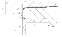
- FIG. 2 is an enlarged cross-sectional view showing the periphery of the mounting portion of the seal member on the right side of FIG. 1. It is sectional drawing which shows the measuring process of the film thickness which concerns on this embodiment. It is sectional drawing which shows the measuring process of the film thickness which concerns on this embodiment. It is sectional drawing which shows the conventional film thickness measurement process. It is sectional drawing of the axle bearing device which concerns on other embodiment of this invention. It is sectional drawing which expands and shows the one end part side of a rolling bearing. It is sectional drawing which expands and shows the edge part of an outer ring.
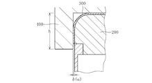
- FIG. 10 is a cross-sectional view of a conventional rolling bearing in which an insulating coating is provided on the surface of an outer ring. It is sectional drawing of the conventional rolling bearing provided with the chamfered part which has an insulating coating.
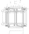
- FIG. 1 is a sectional view showing an embodiment of an electrolytic corrosion preventing rolling bearing according to the present invention.
- the electrolytic corrosion-preventing rolling bearing 1 of this embodiment is a so-called hermetic double-row rolling bearing, and is used, for example, for supporting an axle of a railway vehicle.
- This rolling contact bearing for preventing electrolytic corrosion includes an inner ring 4 having a raceway surface 4a on the outer peripheral surface, an outer ring 5 having a raceway surface 5a on the inner peripheral surface, and a raceway surface 4a of the inner ring 4 and a raceway surface 5a of the outer ring 5.
- a sealed double-row tapered roller bearing that uses tapered rollers as the rolling elements 6 is illustrated.
- a pair of axially separated inner rings 4 is used.
- a raceway surface 4a is formed on the outer peripheral surface of each inner ring 4.
- the outer ring 5 is a so-called double-row outer ring having a double-row (two-row) raceway surface 5a formed on the inner peripheral surface.
- a plurality of rolling elements 6 are respectively arranged between the raceway surface 4a of the inner ring 4 and the raceway surface 5a of the outer ring 5 of each row, whereby a two-row roller row including a plurality of rolling elements 6 is provided for each row. It is formed separately in the axial direction.
- the inner ring 4 is press-fitted and fixed to the outer circumference of the axle 2, and the outer ring 5 is fitted and fixed to the inner circumference of a housing (not shown).
- the seal device 8 is composed of a seal case 81 as a seal member, which is attached to the outer ring 5, and an oil seal 82 attached to the inner circumference of the seal case 81.
- the oil seal 82 has a seal lip 82a made of an elastic material.
- a contact type seal is formed by bringing the seal lip 82a of each oil seal 82 into contact with the outer peripheral surfaces of the oil drainer 9 and the rear lid 10 that are fitted to the outer periphery of the axle shaft 2 with the rolling bearing interposed therebetween. It is possible to prevent leakage of the grease filled in the bearing inner space and intrusion of foreign matter (dust, rainwater, etc.) into the bearing inner space.
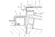
- FIG. 2 shows an enlarged view of the structure near the mounting portion of the sealing device 8 on the right side of FIG.
- the seal case 81 has a cylindrical fitting portion 81a at its outer diameter side end.
- a bead 81a1 protruding in the outer diameter direction is annularly provided on the outer peripheral surface at the tip of the fitting portion 81a.
- Cylindrical surface-shaped seal fitting surfaces 5b are formed on the inner peripheral surfaces of both ends of the outer ring 5.
- the seal fitting surface 5b is formed to have a larger diameter than the inner diameter of the outer end of the raceway surface 5a of the outer ring 5 (the end of the raceway surface 5a on the outer ring end side).
- a bead groove 5c having a groove bottom surface having a diameter larger than that of the seal fitting surface 5b, and a tip surface 81a2 of the fitting portion 81a of the seal case 81.
- a seal regulating surface 5d extending in the radial direction is formed so as to be able to contact in the axial direction.
- the seal regulation surface 5d is formed, for example, by extending the wall surface on the raceway surface 5a side of the wall surfaces on both sides of the bead groove 5c in the axial direction toward the inner diameter side.
- the inner diameter end of the seal regulation surface 5d intersects the outer end of the raceway surface 5a of the outer ring 5.
- the seal device 8 is attached to the outer ring 5 by press-fitting the fitting portion 81a of the seal case 81 into the seal fitting surface 5b of the outer ring 5.
- the fitting portion 81a of the seal case 81 is elastically deformed in the diameter reducing direction by the interference between the bead 81a1 and the seal fitting surface 5b.
- the fitting portion 81a elastically returns in the radial direction, and the bead 81a is accommodated in the bead groove 5c.
- the seal case 81 is prevented from coming off due to the axial engagement between the bead 81a1 and the bead groove 5c, and the tip end surface 81a2 of the fitting portion 81a abuts the seal regulation surface 5d, whereby the seal case 81 is pushed in the pushing direction. Movement is restricted. As a result, the axial positioning of the seal case 81 and, by extension, the seal device 8 is performed.
- the seal fitting surface 5b, the bead groove 5c, and the seal regulation surface 5d of the outer ring 5 are formed by cutting. After this cutting, heat treatment is performed, and then the seal fitting surface 5b and the seal regulating surface 5d of the outer ring 5 are finished by grinding. As a result, the seal fitting surface 5b and the seal restricting surface 5d of the outer ring 5 become grinding surfaces with grinding marks left on the surfaces.
- the surface of the bead groove 5c becomes an unprocessed surface that has not been subjected to post-processing after the heat treatment (cutting marks remain on the surface of the bead groove 5c).
- the surface roughness of the seal fitting surface 5b and the seal regulating surface 5d is higher than the surface roughness of the bead groove 5c. Get smaller.
- the magnitude of the surface roughness here can be evaluated by, for example, the arithmetic average roughness Ra defined in JIS B0031.
- At least the seal regulation surface 5d of the outer ring 5 may be formed by quenching steel cutting, and the machining of the seal regulation surface 5d may be completed only by the cutting (grinding after cutting is not performed).
- Hardened steel cutting is a process in which cutting is performed after quenching of a steel material, and high surface accuracy comparable to a ground surface obtained in a general manufacturing process of machine parts (cutting ⁇ heat treatment ⁇ grinding) is obtained.
- the seal fitting surface 5b and further the bead groove 5c may be formed by cutting hardened steel.
- the seal control surface 5d As a ground surface or a surface formed by cutting hardened steel, it becomes possible to use the seal control surface 5d as a measurement reference surface in the film thickness measurement step described later.
- the seal restricting surface 5d is only a surface for positioning the sealing device 8 in the axial direction, and is not a surface for which accuracy is particularly required. Therefore, the seal regulation surface 5d of the existing product is usually left as it is as a cutting surface with low accuracy.
- the present embodiment differs from the existing sealed type double row rolling bearing in that the seal regulation surface 5d is processed with high precision by grinding or quenching steel cutting.
- seal regulation surface 5d is preferably finished so that its surface roughness (for example, arithmetic mean roughness Ra) is 1.6 ⁇ m or less.
- the outer peripheral surface 5e of the outer ring 5, the width surfaces 5f on both sides in the axial direction, and the inner diameter chamfer 5g (the chamfer between the width surface 5f and the seal fitting surface 5b) located on the inner diameter side of the width surface 5f are all continuous insulating coatings 3 Covered with.
- the insulating coating 3 is formed by a known method of spraying ceramics or the like. The insulating coating 3 is not formed on the raceway surface 5a, the seal fitting surface 5b, the surface of the bead groove 5c, and the seal regulating surface 5d provided on the inner peripheral side of the outer ring 5, and the steel material serving as the base material is exposed. is doing.
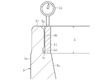
- the film thickness of the insulating coating 3 covering both width surfaces 5f is measured with the seal regulation surface 5d of the outer ring 5 as a measurement reference. As shown in FIG. 3, the film thickness measurement is performed by placing the outer ring 5 in a posture in which the axial direction of the outer ring 5 is vertical and the width surface 5f to be measured is upward. Specifically, before forming the insulating coating 3, a measuring jig 11 such as a block gauge is arranged on the seal regulating surface 5d.
- the measuring element of a measuring instrument held by an appropriate holding jig for example, a comparative measuring instrument such as a dial gauge 12 is pressed against the upper surface of the measuring jig 11 to adjust the zero point, the measuring element is attached to the width surface 5f of the outer ring 5. Then, the distance A between the seal regulation surface 5d and the width surface 5f of the outer ring 5 is obtained from the measured value and the length of the measurement jig 11. After that, the insulating coating 3 that covers the outer peripheral surface 5e, the width surface 5f, and the inner diameter chamfer 5g of the outer ring 5 is formed.
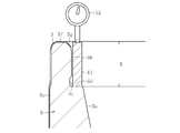
- the same measuring jig 11 as described above is arranged on the seal regulating surface 5d, and the procedure from the reference surface 5d to the surface of the insulating coating 3 covering the width surface 5f is performed in the same procedure.
- the distance B is measured with the dial gauge 12.
- the film thickness of the insulating coating 3 can be obtained by calculating B ⁇ A.
- the seal regulation surface 5d on the axially opposite side is used as a measurement reference, and the insulating film 3 covering the width surface 5f is subjected to the same procedure as above. Measure the film thickness.
- the outer ring 5 is completed by grinding the surfaces of the insulating coating 3 that covers both width surfaces 5f so as to be within the allowable range of the width finishing dimension.
- the inner ring 4, the rolling element 6, and the cage 7 are assembled to the outer ring 5, and the seal device 8 is press-fitted and fixed to the seal fitting surface 5b of the outer ring 5, thereby forming the sealed double-row tapered roller shown in FIG. The bearing is completed.
- the existing seal regulation surface 5d existing in the outer ring 5 near the mounting portion of the seal member (seal case 81) constituting the sealing device 8 is used as a reference surface for film thickness measurement.
- the double-row tapered roller bearing is illustrated as the double-row rolling bearing, but the application target of the present invention is not limited to this.
- the double-row cylindrical rolling bearing using cylindrical rollers as the rolling elements may be applied. You can also
- the bearing using the electrolytic corrosion prevention rolling bearing according to the present embodiment, an example of an axle bearing that supports an axle of a railway vehicle has been illustrated, but the application target of this electrolytic corrosion prevention rolling bearing is not limited to this, and a rolling bearing
- the present invention can be widely applied to rolling bearings used for supporting shafts in devices/apparatuses that should avoid energization via.
- the configuration of the sealing device 8 is also arbitrary, and a sealing device having a configuration other than that illustrated in FIG. 1 can be used.
- the core metal is used as the seal member.
- An axle bearing device 50 according to another embodiment of the present invention shown in FIG. 6 rotatably supports an axle of a railway vehicle.
- a bearing device 50 for an axle includes a rolling bearing 1 attached to the outer periphery of an axle (not shown), a pair of seal members (sealing devices) 8, an axle box 51 as a housing, and a rolling element.
- An oil drainer 9 provided on the vehicle outer side (left side in FIG. 6) of the bearing 1 and a rear lid 10 provided on the vehicle inner side (right side in FIG. 6) of the rolling bearing 1 are provided.
- the rolling bearing 1 is a so-called double-row tapered roller bearing, which has a double-row inner raceway surface 4a, an inner ring 4 fixed to the outer periphery of the axle, and a double-row outer raceway surface 5a.
- a tapered roller 6 Fixed to the outer ring 5, a tapered roller 6 as a rolling element arranged between the raceways 4a, 5a of the inner and outer rings 4, 5, and a pair of tapered rollers 6 for holding each row at predetermined intervals in the circumferential direction.
- a retainer 7 In the illustrated example, a spacer (spacer) 15 is interposed between a pair of divided inner rings forming the inner ring 4, but a pair of divided inner rings are directly butted against each other in the axial direction, or a single member is used. It may be one. Sealed plates 16 are interposed between the inner ring 4 and the oil drainer 9 and between the inner ring 4 and the rear lid 10, respectively.
- the seal member 8 is composed of a ring-shaped oil seal 82 and a ring-shaped seal case 81 that holds the oil seal 82 on the inner circumference.
- the seal member 8 may not be provided with the seal case 81 and may be composed of only the oil seal 82.
- the oil seal 82 is slidably attached to the outer peripheral surface of the oil drainer 9 or the rear lid 10.
- the seal case 81 is press-fitted between the inner ring 4 and the outer ring 5 to be fitted and fixed to the inner peripheral surface of the outer ring 5 (tight fit). Further, the end portion of the seal case 81 is close to the oil drainer 9 or the rear lid 10, and between the seal case 81 and the oil drainer 9 and between the seal case 81 and the rear lid 10. A labyrinth seal is formed.
- FIG. 7 is an enlarged view showing one end side (the left end side in FIG. 6) of the rolling bearing 1.
- an insulating coating (insulating layer) 3 made of ceramics or the like is provided on the surface of the outer ring 5 in order to prevent electrolytic corrosion of the rolling bearing 1 due to creeping discharge or the like.
- the insulating coating 3 is provided from the outer peripheral surface 5e of the outer ring 5 to the end surface (width surface) 5f, which is the surface with which the shaft box 51 contacts.
- the insulating coating 3 has a corner portion (inner diameter chamfer) 5g between the end surface 5f of the outer ring 5 and the inner peripheral surface (seal fitting surface) 5b, or the vicinity of the inner peripheral surface 5b.
- the seal case 81 When the seal case 81 is mounted, the seal case 81 may come into contact with the insulating coating 3 on the corner 5g.
- the insulating case 3 When the insulating case 3 is damaged by the contact of the seal case 81 with the insulating film 3, the insulating performance may be deteriorated and electrolytic corrosion may occur. Therefore, in this embodiment, the following measures are taken in order to avoid damage to the insulating coating 3.
- FIG. 8 is a cross-sectional view showing an enlarged end portion of the outer ring 5.
- the first chamfered portion A and the second chamfered portion B inclined at mutually different angles are provided between the end surface 5f of the outer ring 5 and the inner peripheral surface 5b (corner portion 5g). It is provided.
- the first chamfered portion A is arranged axially outside (left side in FIG. 8) of the second chamfered portion B, and is inclined at an angle ⁇ 1 with respect to the end surface 5f of the outer ring 5.
- the second chamfered portion B is arranged axially inward of the first chamfered portion A (on the right side in FIG.
- Each of the first chamfered portion A and the second chamfered portion B is formed by a linear inclined surface, and is continuous with each other through a sharp corner between them.
- An insulating coating 3 is provided on the surface of the first chamfered portion A. On the other hand, the insulating coating 3 is not provided on the surface of the second chamfered portion B.
- the second chamfered portion B does not have the insulating coating 3 at all, but there may be a portion where the insulating coating 3 is slightly formed. Specifically, of the entire surface area of the second chamfered portion B, the area where the insulating coating 3 is not provided may be 90% or more. Therefore, the phrase "the insulating coating is not provided" as used herein means that the insulating coating 3 is not provided at all on the second chamfered portion B, and the insulating coating is included in the surface area of the entire second chamfered portion B. The case where the area of the portion where 3 is not provided is 90% or more is also included.
- the second chamfered portion B is used as a guide surface when the seal case is mounted. can do. That is, when the seal case 81 is mounted in the bearing, the seal case 81 can be easily mounted in the bearing by bringing the outer peripheral surface of the seal case 81 into contact with and guiding the second chamfered portion B. Further, at this time, even if the seal case 81 contacts the second chamfered portion B, since the insulating coating 3 is not provided on the second chamfered portion B, the contact of the seal case 81 may damage the insulating coating 3. There is no.
- the creepage distance ⁇ 1 (see FIG. 8) from the axle box 51 to the non-insulated portion of the outer ring 5 can be increased. That is, when the insulating coating 3 is not provided on the chamfered portion C as in the comparative example shown in FIG. 9, the creepage distance ⁇ 2 cannot be lengthened in the axial direction, but as in the present embodiment shown in FIG. In addition, since the insulating coating 3 is provided on the first chamfered portion B, the creepage distance ⁇ 1 can be extended in the axial direction and lengthened. As a result, the insulating performance of the rolling bearing is improved, and electrolytic corrosion due to creeping discharge can be effectively prevented.
- the seal case 81 can be guided by the second chamfered portion B and easily mounted in the bearing without damaging the insulating coating 3 of the first chamfered portion A.
- the creepage distance can be increased and the insulation performance can be improved.
- the insulating coating may be damaged when the seal member is mounted in the bearing. Therefore, when the present invention is applied to such a rolling bearing, a great effect can be expected.
- the housing such as the axle box 51 can be brought into contact with the end surface 5f of the outer ring 5 over a wide range (to a position close to the inner peripheral surface 5b of the outer ring 5). become. As a result, the axial movement of the rolling bearing 1 can be reliably regulated and positioned.
- the first chamfered portion A and the second chamfered portion B are inclined at different angles, only the thermal spraying of the insulating material from the axial direction allows the second chamfered portion B to be formed.
- the insulating coating 3 can be formed on the first chamfered portion A and the end surface 5f of the outer ring 5 without adhering an insulating material thereto. Therefore, it is possible to maintain productivity without increasing the number of spraying steps.
- the present invention is not limited to the configuration in which the insulating coating 3 is provided on the outer ring 5 as in the above-described embodiment, but can be applied to the configuration in which the insulating coating 3 is provided on the inner ring 4.
- the seal member 8 mounted in the bearing 4 is fitted and fixed to the outer peripheral surface 4c of the inner ring 4 by press fitting (tight fit), as in the example shown in FIG.
- the insulating coating 3 is provided in the vicinity of the outer peripheral surface 4c (in the illustrated example, the insulating coating 3 is provided on the inner peripheral surface 4b and the end surface 4d of the inner ring 4), insulation is provided when the seal member 8 is mounted.
- the coating film 3 may be damaged. Therefore, even with respect to such an inner ring 4, as shown in FIG. 11, between the end surface 4d and the outer peripheral surface 4c of the inner ring 4, the insulating coating 3 is inclined inward in the axial direction with respect to the end surface 4d of the inner ring 4.
- the insulation performance is improved as in the above-described embodiment. At the same time, it is possible to prevent the insulating coating from being damaged due to the mounting of the seal member. 10 and 11, the members having the same reference numerals as those in FIGS. 6 to 8 are members having the same function or shape, and the description thereof will be omitted.
- the present invention is not limited to the tapered roller bearing, but to a cylindrical roller bearing, a deep groove ball bearing, or other rolling bearings. Is also applicable. Alternatively, a single row rolling bearing may be used.
- the present invention is not limited to rolling bearings (bearings for railway vehicle axles) that support the axles of railway vehicles, but is also applicable to rolling bearings used for general-purpose motors, generator generators, wind power generators, and the like.
- Electrolytic corrosion prevention rolling bearing 2 Axle 3 Insulation coating 4 Inner ring 4a Raceway surface 5 Outer ring 5a Raceway surface 5b Seal fitting surface 5c Bead groove 5d Seal regulation surface 5e Outer peripheral surface 5f Width surface 5g Inner diameter chamfer 6
- Sealing device 11 Measuring jig (block gauge) 12 Measuring instrument (dial gauge) 81 Seal member (seal case) 81a1 bead 81a2 End surface (tip surface) of seal member 82 Oil seal A First chamfer B Second chamfer
Landscapes
- Engineering & Computer Science (AREA)
- General Engineering & Computer Science (AREA)
- Mechanical Engineering (AREA)
- Manufacturing & Machinery (AREA)
- Rolling Contact Bearings (AREA)
Abstract
複列円すいころ軸受1は、外周に軌道面4aを有する内輪4と、内周に軌道面5aを有する外輪5と、内輪4の軌道面4aと外輪5の軌道面5aの間に介在する複列の円すいころ6と、内輪4と外輪5の間の軸受内部空間を軸方向両側で密封するシール部材81とを備える。外輪5は、シール部材81の端面81a2と軸方向で当接可能のシール規制面5dを有し、外輪5の外周面5eから幅面5fに渡って絶縁被膜3が設けられている。
Description
本発明は、複列円すいころ軸受に関する。
鉄道車両の車軸などを支持する転がり軸受として、内輪と外輪の間を密封するシール部材を備える複列円すいころ軸受が知られている(特許文献1参照)。
複列円すいころ軸受を備える鉄道車両などにおいては、主電動機の電流を車輪からレールへ接地する接地用集電装置が不完全な場合に、主電動機の電流が軸受の内外輪及び円すいころを通って、車輪とレール間に流れることがある。このとき、円すいころと外輪軌道面との間又は内輪軌道面との間で放電が生じ、放電部分に電食が発生する。
そこで、本発明は、電食を防止できる複列円すいころ軸受を提供することを目的とする。
前記課題を解決するためになされた本発明は、外周に軌道面を有する内輪と、内周に軌道面を有する外輪と、内輪の軌道面と外輪の軌道面の間に介在する複列の円すいころと、内輪と外輪の間の軸受内部空間を軸方向両側で密封するシール部材とを備え、外輪は、シール部材の端面と軸方向で当接可能のシール規制面を有し、外輪の外周面から幅面に渡って絶縁被膜が設けられている複列円すいころ軸受である。
このように、本発明に係る複列円すいころ軸受においては、シール部材を外輪のシール規制面に当接させて軸方向の位置決めを行いつつ、外輪の外周面から幅面に渡って絶縁被膜が設けられていることで、絶縁性を確保して電食を防止することができる。
ところで、外輪の外周面から両幅面に至る全域にセラミックス等を溶射することで絶縁被膜を形成する現状の溶射技術では、溶射後に形成される絶縁被膜の膜厚のばらつきが大きいため、絶縁被膜の表面を研削して最終仕上げ寸法に仕上げる必要がある。その一方で、研削時の削り代が大きすぎると膜厚不足となり、必要な絶縁性を確保できない。そのため、絶縁被膜の形成後には、その膜厚管理が必要とされる。
絶縁被膜の膜厚を測定する方法として、特開2009-24883号公報に記載のものが知られている。これは、図5に示すように、外輪100の幅面101の内周縁部に環状の段部103を設け、この段部の内面104を膜厚測定の基準面とするものである。具体的には、先ず、絶縁被膜の形成前に、基準面104と反基準面側の幅面102との間の幅寸法Aを測定する。次いで、絶縁被膜105を形成し、その後、基準面104と反基準面側の幅面102を覆う絶縁被膜の表面との間の幅寸法Bを測定し、反基準面側の幅面102に形成した絶縁被膜105の取り代を決定する。次に、基準面104をバッキングプレートに当てながら反基準面側の幅面102を覆う絶縁被膜105を機械加工し、その後、目標寸法である幅仕上げ寸法と、外輪100の絶縁被膜を含む全幅寸法Cとから、もう一方の絶縁被膜の取り代を決定する。その後、幅面102を覆う加工済みの絶縁被膜105の表面を基準とし、幅仕上げ寸法の許容範囲内に入るように、逆側幅面を加工する。
この膜厚管理法では、外輪100の幅面101の内周縁部に、基準面104を形成するための環状の段部103を設ける必要がある。しかしながら、外輪の幅面101の径方向寸法が短い場合には、基準面を設けることができず、膜厚測定を行うことが困難となる。
他の膜厚測定法として、電磁波を照射して膜厚を測定する膜厚計を使用することも考えられるが、外輪の幅面の径方向寸法が短い場合には、膜厚計のプローブが幅面からはみ出でしまい、同様に、膜厚測定が困難となる。
そこで、軸受サイズを大型化することなく、膜厚測定のための基準面を確保できるようにするために、前記シール規制面を研削面とすることが好ましい。
シール規制面が、高い表面精度を有する研削面で形成されることで、シール規制面を膜厚測定時の基準面として利用することができる。また、このシール規制面は、シール部材を外輪に取り付ける際の取り付け部付近に存在する既設面であり、このシール規制面を基準面として用いる際には、新たに基準面を設ける必要がない。そのため、外輪の幅面の半径方向寸法が小さい場合にも、精度良く膜厚を測定することが可能となる。
シール規制面が焼入れ鋼切削で形成された面であっても、当該面が高い表面精度を有するため、シール規制面を膜厚測定時の基準面として用いることができる。従って、上記と同様の作用効果を得ることができる。
また、外輪が、シール部材の外周面と嵌合するシール嵌合面と、シール嵌合面と軌道面との間に設けられ、シール部材の外周面に設けたビードと係合して、シール部材の軸方向の抜け止めを行うビード溝を有する構成の場合、シール規制面の表面粗さを、ビード溝の表面粗さよりも小さくしてもよい。
かかる構成によっても、シール規制面が高い表面精度を有するため、シール規制面を膜厚測定時の基準面として用いることができ、上記と同様の作用効果を得ることができる。
図12は、外輪200の表面に絶縁被膜300が設けられた従来の転がり軸受(玉軸受)の断面図である。
図12に示す転がり軸受は、鉄道車両の車軸を支持する転がり軸受である。この種の転がり軸受においては、外輪200が軸方向に移動しないように軸箱などのハウジング400によって固定される。ここで、確実に外輪200を固定するには、図12に示すように、ハウジング400の肩高さhを大きくし、ハウジング400と外輪200との接触面積を大きく確保する必要がある。しかしながら、このように、ハウジング400の肩高さhを大きくすると、ハウジング400と外輪200(非絶縁部)との間の沿面距離αが絶縁被膜300の厚みδ分だけとなるため(α=δ)、ハウジング400と外輪200との間に一定以上の電位差が生じた場合に、絶縁被膜300の端部に沿って沿面放電が生じ、電食が発生する虞がある。
斯かる沿面放電の問題を解決するため、特開2007-205555号公報では、図13に示すように、外輪200の角部に面取り部200aを形成し、面取り部200aを絶縁被膜300で被覆する構成が提案されている。この場合、ハウジングと外輪(非絶縁部)との間の沿面距離αが、面取り部200aの軸方向長さγ分だけ増加するので(α=δ+γ)、軸受の絶縁性能を向上させることができる。なお、本明細書中での「沿面距離」とは、2つの導体間に挟まれた絶縁被膜(絶縁部材)の表面に沿った最小距離を言う。
しかしながら、図13に示すような絶縁被膜300を有する面取り部200aがあると、外輪と内輪の間にシール部材を装着する際にシール部材が面取り部200aの絶縁被膜300に接触することで、絶縁被膜300が損傷する虞がある。
特に、鉄道車両の車軸を支持する転がり軸受においては、耐環境性と強度を確保するために、シール部材として樹脂製のものを用いることができないため(金属製の芯金を有する剛性の高いシール部材を使用する必要があるため)、シール部材が絶縁被膜に接触した際に、絶縁被膜が損傷する可能性が大きくなる。
そこで、このようなシール部材の装着に伴う絶縁被膜の損傷を防止し、絶縁性能の向上を図るため、外輪の幅面と内周面との間に、外輪の幅面よりも軸方向内側に傾斜する第1面取り部を設けると共に、第1面取り部の軸方向内側に、外輪の幅面に対して第1面取り部よりも軸方向内側に大きく傾斜する第2面取り部を設け、第1面取り部の表面に絶縁被膜が設けられ、第2面取り部の表面に絶縁被膜は設けられていないようにすることが好ましい。
このように、外輪の端面と内周面との間に、絶縁被膜を有する第1面取り部と、絶縁被膜を有しない第2面取り部とを設けることで、第1面取り部の絶縁被膜を損傷させることなく、シール部材を軸受内に容易に装着することができる。すなわち、シール部材を軸受内に装着する際、シール部材の外周面を第2面取り部に接触させて案内することで、シール部材を軸受内に容易に装着することができる。このとき、シール部材が第2面取り部に接触しても、第2面取り部には絶縁被膜が設けられていないので、シール部材の接触による絶縁被膜の損傷の虞はない。一方、第1面取り部には絶縁被膜が設けられていることで、第1面取り部が外輪の端面よりも軸方向内側に傾斜している分、沿面距離が長くなり、絶縁性能を向上させることができる。また、沿面距離が長くなることで、外輪を固定するハウジングを外輪の端面に対して広い範囲に渡って(外輪の内周面に近い位置にまで)接触させることができるようになり、転がり軸受の軸方向移動を確実に規制して位置決めできるようになる。
本発明に係る複列円すいころ軸受は、例えば、鉄道車両の車軸を支持する鉄道車両車軸用軸受に用いることが可能である。
本発明によれば、シール部材を外輪のシール規制面に当接させて軸方向の位置決めを行いつつ、絶縁性を確保して電食を防止することができる。
以下、本発明に係る電食防止転がり軸受の実施形態を、図1~4に基づいて説明する。
図1は、本発明にかかる電食防止転がり軸受の一実施形態を示す断面図である。この実施形態の電食防止転がり軸受1は、いわゆる密封形複列転がり軸受であり、例えば鉄道車両の車軸の支持に用いられる。
この電食防止転がり軸受は、外周面に軌道面4aを有する内輪4と、内周面に軌道面5aを有する外輪5と、内輪4の軌道面4aと外輪5の軌道面5aとの間に介在させた転動体6と、転動体6を円周方向等間隔に保持する保持器7と、内輪4と外輪5の間の環状空間(軸受内部空間)を軸方向両側で密封するシール装置8とを主要な要素として構成される。本実施形態では、転動体6として円すいころを使用した、密封形複列円すいころ軸受を例示している。
内輪4として、軸方向に離間した一対が使用される。各内輪4の外周面に軌道面4aが形成されている。外輪5は、内周面に複列(2列)の軌道面5aが形成されたいわゆる複列外輪である。各列の内輪4の軌道面4aと外輪5の軌道面5aとの間にそれぞれ複数の転動体6が配置され、これにより、列毎に複数の転動体6を備えた二列のころ列が軸方向に離間して形成される。内輪4は車軸2の外周に圧入固定され、外輪5は図示しないハウジングの内周に嵌合固定される。
シール装置8は、外輪5に取り付けられる、シール部材としてのシールケース81と、シールケース81の内周に取付けたオイルシール82とで構成される。オイルシール82は、弾性材料からなるシールリップ82aを有する。転がり軸受を間に挟んで車軸2の外周に嵌合した油切り9および後蓋10の外周面に、各オイルシール82のシールリップ82aを接触させることにより、接触式シールが構成され、そのため、軸受内部空間に封入されたグリースの漏洩や軸受内部空間への異物(塵埃、雨水等)の侵入を防止することが可能となる。
図2に、図1の右側のシール装置8の取り付け部付近の構造を拡大して示す。
図2に示すように、シールケース81は、その外径側の先端に円筒状の嵌合部81aを備えている。嵌合部81aの先端の外周面には、外径方向に突出するビード81a1が環状に設けられている。外輪5の両端部の内周面には、円筒面状のシール嵌合面5bが形成される。このシール嵌合面5bは、外輪5の軌道面5aの外端(軌道面5aのうち外輪端部側の端部)の内径寸法よりも大径に形成されている。外輪5の軌道面5aとシール嵌合面5bとの間には、溝底面をシール嵌合面5bよりも大径にしたビード溝5cと、シールケース81の嵌合部81aの先端面81a2と軸方向で当接可能となるように半径方向に延びたシール規制面5dとが形成される。シール規制面5dは、例えばビード溝5cの軸方向両側の壁面のうち、軌道面5a側の壁面を内径側に延ばすことで形成される。シール規制面5dの内径端部は、外輪5の軌道面5aの外端と交わっている。
図2に示すように、シールケース81は、その外径側の先端に円筒状の嵌合部81aを備えている。嵌合部81aの先端の外周面には、外径方向に突出するビード81a1が環状に設けられている。外輪5の両端部の内周面には、円筒面状のシール嵌合面5bが形成される。このシール嵌合面5bは、外輪5の軌道面5aの外端(軌道面5aのうち外輪端部側の端部)の内径寸法よりも大径に形成されている。外輪5の軌道面5aとシール嵌合面5bとの間には、溝底面をシール嵌合面5bよりも大径にしたビード溝5cと、シールケース81の嵌合部81aの先端面81a2と軸方向で当接可能となるように半径方向に延びたシール規制面5dとが形成される。シール規制面5dは、例えばビード溝5cの軸方向両側の壁面のうち、軌道面5a側の壁面を内径側に延ばすことで形成される。シール規制面5dの内径端部は、外輪5の軌道面5aの外端と交わっている。
シール装置8は、外輪5のシール嵌合面5bにシールケース81の嵌合部81aを圧入することで外輪5に取り付けられる。圧入に伴い、ビード81a1とシール嵌合面5bの干渉によりシールケース81の嵌合部81aが縮径方向に弾性変形する。ビード81a1がビード溝5cと対向すると同時に嵌合部81aが拡径方向に弾性的に復帰し、ビード81aがビード溝5cに収容される。ビード81a1とビード溝5cとの軸方向の係合によりシールケース81の抜け止めがなされ、嵌合部81aの先端面81a2がシール規制面5dと当接することにより、シールケース81の押し込み方向への移動が規制される。これにより、シールケース81、延いてはシール装置8の軸方向の位置決めがなされる。
外輪5の製作工程では、外輪5のシール嵌合面5b、ビード溝5c、およびシール規制面5dが切削により形成される。この切削後に熱処理を行い、その後、外輪5のシール嵌合面5bおよびシール規制面5dが研削により仕上げられる。これにより外輪5のシール嵌合面5bおよびシール規制面5dが、表面に研削痕の残る研削面となる。また、ビード溝5cの表面は、熱処理後に後加工を行っていない未加工面となる(ビード溝5cの表面には切削痕が残っている)。研削面の表面精度は切削面(切削で仕上げられた面)の表面精度よりも良好であるため、シール嵌合面5bおよびシール規制面5dの表面粗さは、ビード溝5cの表面粗さよりも小さくなる。ここでの表面粗さの大小は、例えば、JIS B0031で定義される算術平均粗さRaで評価することができる。
この他、外輪5の少なくともシール規制面5dを焼入れ鋼切削により形成し、当該切削だけでシール規制面5dの加工を終了してもよい(切削後の研削は行わない)。焼入れ鋼切削は、鋼材の焼入れ後に切削を行う工程であり、機械部品の一般的な製造工程(切削→熱処理→研削)で得られる研削面に匹敵する高い表面精度が得られる。なお、シール規制面5dだけでなく、シール嵌合面5b、さらにはビード溝5cも焼入れ鋼切削で形成しても構わない。
このようにシール規制面5dを研削面あるいは焼入れ鋼切削で形成された面とすることで、後で述べる膜厚測定工程において、シール規制面5dを測定基準面として用いることが可能となる。既存の密封形複列転がり軸受において、シール規制面5dは、シール装置8の軸方向の位置決めを行う面にすぎず、特に精度が必要とされる面ではない。そのため、既存品のシール規制面5dは、精度の低い切削面のままで放置されるのが通例である。本実施形態は、このシール規制面5dを、研削あるいは焼入れ鋼切削等により高精度に加工した点で、既存の密封形複列転がり軸受と異なる。
なお、シール規制面5dは、その表面粗さ(例えば算術平均粗さRa)が1.6μm以下となるように仕上げるのが好ましい。
外輪5の外周面5e、軸方向両側の幅面5f、および、幅面5fの内径側に位置する内径チャンファ5g(幅面5fとシール嵌合面5bの間のチャンファ)は、何れも連続した絶縁被膜3で覆われる。この絶縁被膜3は、セラミックス等を溶射する公知の手法により形成される。外輪5の内周側に設けられた軌道面5a、シール嵌合面5b、ビード溝5cの表面、およびシール規制面5dには絶縁被膜3は形成されておらず、母材となる鋼材が露出している。
以上に述べた絶縁被膜3を有する密封形複列転がり軸受の製造工程では、外輪5のシール規制面5dを測定基準として、両幅面5fを覆う絶縁被膜3の膜厚の測定が行われる。膜厚測定は、図3に示すように、外輪5を、その軸方向を垂直方向に向け、かつ測定する幅面5fを上に向けた姿勢で載置することにより行われる。具体的には、絶縁被膜3の形成前に、シール規制面5dにブロックゲージ等の測定治具11を配置する。次に、適宜の保治具で保持した測定器、例えばダイヤルゲージ12等の比較測定器の測定子を測定治具11の上面に押し当てて零点を合せた後、外輪5の幅面5fに測定子を押し当て、測定値と測定治具11の長さとから、シール規制面5dと外輪5の幅面5fとの間の距離Aを求める。その後、外輪5の外周面5e、幅面5f、および内径チャンファ5gを覆う絶縁被膜3を形成する。
絶縁被膜3の形成後、図4に示すように、上記と同じ測定治具11をシール規制面5dに配置し、同様の手順で、基準面5dから幅面5fを覆う絶縁被膜3の表面までの距離Bをダイヤルゲージ12で測定する。B-Aを算出することで、絶縁被膜3の膜厚が求めることができる。
軸方向反対側(図1の図面左側)の外輪5の幅面5fについても、軸方向反対側のシール規制面5dを測定基準とし、上記と同様の手順で、当該幅面5fを覆う絶縁被膜3の膜厚を測定する。
その後、測定した膜厚値に応じて、幅仕上げ寸法の許容範囲内に入るように、両幅面5fを覆う絶縁被膜3の表面をそれぞれ研削することにより、外輪5が完成する。その後、外輪5に内輪4、転動体6、および保持器7を組み付け、さらに外輪5のシール嵌合面5bに、シール装置8を圧入固定することで、図1に示す密封形複列円すいころ軸受が完成する。
本実施形態では、外輪5のうち、シール装置8を構成するシール部材(シールケース81)の取り付け部付近に存在する既設のシール規制面5dを膜厚測定用の基準面として活用しているため、新たに基準面を設ける必要がない。そのため、特許文献1に記載の膜厚管理法のように、外輪5の幅面5fの半径方向寸法を大きくする必要はなく、外輪5の端部の半径方向の肉厚を薄くすることができる(例えば7mm以下の肉厚にすることも可能となる)。従って、複列転がり軸受の小型化を達成しつつ、絶縁被膜3の膜厚管理を精度よく行うことが可能となり、信頼度の高い絶縁性を得ることができる。
以上の説明では、複列転がり軸受として複列円すいころ軸受を例示したが、本発明の適用対象はこれに限定されず、例えば転動体として円筒ころを用いた複列円筒転がり軸受に適用することもできる。
また、本実施形態に係る電食防止転がり軸受を使用した軸受として、鉄道車両の車軸を支持する車軸軸受を例示したが、この電食防止転がり軸受の適用対象はこれに限定されず、転がり軸受を介した通電を避けるべき機器・装置における軸の支持に使用される転がり軸受に広く適用することができる。シール装置8の構成も任意であり、図1に例示した以外の構成のシール装置を用いることができる。例えば芯金の先端にシールリップを形成し、この芯金を外輪5に取り付けたシール装置8を使用することもできる。この場合、芯金がシール部材として用いられる。
次に、本発明の他の実施形態について説明する。
図6に示す本発明の他の実施形態に係る車軸用軸受装置50は、鉄道車両の車軸を回転自在に支持する。図1に示すように、車軸用軸受装置50は、車軸(図示省略)の外周に取り付けられた転がり軸受1と、一対のシール部材(シール装置)8と、ハウジングとしての軸箱51と、転がり軸受1の車両外側(図6の左側)に設けられた油切り9と、転がり軸受1の車両内側(図6の右側)に設けられた後蓋10など、を備える。
転がり軸受1は、いわゆる複列円すいころ軸受であり、複列の内側軌道面4aを有し、車軸の外周に固定された内輪4と、複列の外側軌道面5aを有し、軸箱51に固定された外輪5と、内外輪4,5の軌道面4a,5a間に配置された転動体としての円すいころ6と、円すいころ6の各列を円周方向所定間隔で保持する一対の保持器7と、を備える。図示例では、内輪4を構成する一対の分割内輪の間に間座(スペーサ)15を介在させているが、一対の分割内輪を軸方向に直接突き合わせたものや、単一部材で構成されたものであってもよい。内輪4と油切り9との間、及び、内輪4と後蓋10との間には、それぞれシール付きプレート16が介在している。
シール部材8は、リング状のオイルシール82と、内周にオイルシール82を保持するリング状のシールケース81と、で構成されている。なお、シール部材8は、シールケース81を有さず、オイルシール82のみで構成されるものであってもよい。オイルシール82は、油切り9又は後蓋10の外周面に対して摺接可能に装着されている。一方、シールケース81は、内輪4と外輪5との間に圧入されることにより、外輪5の内周面に嵌合して固定されている(締り嵌め)。また、シールケース81の端部は、油切り9又は後蓋10に対して近接しており、シールケース81と油切り9との間、及び、シールケース81と後蓋10との間に、ラビリンスシールが形成されている。
図7は、転がり軸受1の一端部側(図6における左端部側)を拡大して示す図である。
図7に示すように、転がり軸受1においては、沿面放電などによる転がり軸受1の電食を防止するため、外輪5の表面にセラミックスなどから成る絶縁被膜(絶縁層)3が設けられている。絶縁被膜3は、軸箱51が接触する面である、外輪5の外周面5eから端面(幅面)5fに渡って設けられている。
ここで、本実施形態のように、絶縁被膜3が、外輪5の端面5fと内周面(シール嵌合面)5bとの間の角部(内径チャンファ)5g、あるいは内周面5bの近傍にまで設けられていると、シールケース81を装着する際に、シールケース81が角部5gの絶縁被膜3に接触する可能性がある。そして、シールケース81が絶縁被膜3に接触することにより、絶縁被膜3が損傷すると、絶縁性能が低下し、電食が発生する虞がある。そこで、本実施形態においては、絶縁被膜3の損傷を回避するため、以下のような対策を講じている。
図8は、外輪5の端部を拡大して示す断面図である。
図8に示すように、本実施形態では、外輪5の端面5fと内周面5bとの間(角部5g)に、互いに異なる角度で傾斜する第1面取り部A及び第2面取り部Bが設けられている。第1面取り部Aは、第2面取り部Bよりも軸方向外側(図8の左側)に配置され、外輪5の端面5fに対して角度θ1で傾斜している。一方、第2面取り部Bは、第1面取り部Aよりも軸方向内側(図8の右側)に配置され、外輪5の端面5fに対して第1面取り部Aよりも大きい角度θ2で傾斜している。第1面取り部A及び第2面取り部Bは、それぞれ直線状の傾斜面で形成されており、これらの間の尖った角部を介して互いに連続している。また、第1面取り部Aの表面には絶縁被膜3が設けられている。これに対して、第2面取り部Bの表面には絶縁被膜3は設けられていない。
なお、第2面取り部Bには、絶縁被膜3が全くないことが望ましいが、僅かに絶縁被膜3が形成されている部分があってもよい。具体的には、第2面取り部B全体の表面積のうち、絶縁被膜3が設けられていない部分の面積が90%以上であればよい。従って、ここでいう「絶縁被膜が設けられていない」とは、第2面取り部Bに、絶縁被膜3が全く設けられていない場合のほか、第2面取り部B全体の表面積のうち、絶縁被膜3が設けられていない部分の面積が90%以上である場合も含むものとする。
このように、絶縁被膜3を有する第1面取り部Aとは別に、絶縁被膜3を有しない第2面取り部Bを設けることで、第2面取り部Bを、シールケース装着時のガイド面として利用することができる。すなわち、シールケース81を軸受内に装着する際、シールケース81の外周面を第2面取り部Bに接触させて案内することで、シールケース81を軸受内に容易に装着することができる。また、このとき、シールケース81が第2面取り部Bに接触しても、第2面取り部Bには絶縁被膜3が設けられていないので、シールケース81の接触による絶縁被膜3の損傷の虞はない。
一方、第1面取り部Aには絶縁被膜3が設けられていることで、軸箱51から外輪5の非絶縁部までの沿面距離α1(図8参照)を長くすることができる。すなわち、図9に示す比較例のように、面取り部Cに絶縁被膜3が設けられていない場合は、沿面距離α2を軸方向に長くすることができないが、図8に示す本実施形態のように、絶縁被膜3が第1面取り部Bに設けられていることで、沿面距離α1を軸方向に伸ばして長くすることが可能である。これにより、転がり軸受の絶縁性能が向上し、沿面放電などによる電食を効果的に防止できるようになる。
以上のように、本実施形態に係る転がり軸受によれば、外輪5の端面5fと内周面5bとの間に、絶縁被膜3を有する第1面取り部Aと、絶縁被膜3を有しない第2面取り部Bとを設けることで、第1面取り部Aの絶縁被膜3を損傷させることなく第2面取り部Bによってシールケース81を案内して軸受内に容易に装着することができる。また、第1面取り部Aに絶縁被膜3を設けることで、沿面距離を長くすることができ、絶縁性能の向上も実現できるようになる。特に、鉄道車両用車軸軸受においては、剛性の高いシール部材が用いられるため、シール部材を軸受内に装着する際に絶縁被膜が損傷する虞がある。従って、このような転がり軸受に本発明を適用した場合は、大きな効果を期待できる。
また、沿面距離が長くなることで、軸箱51などのハウジングを外輪5の端面5fに対して広い範囲に渡って(外輪5の内周面5bに近い位置にまで)接触させることができるようになる。これにより、転がり軸受1の軸方向移動を確実に規制して位置決めすることが可能となる。
また、本実施形態に係る転がり軸受においては、第1面取り部Aと第2面取り部Bとが異なる角度で傾斜しているため、軸方向からの絶縁材料の溶射のみで、第2面取り部Bに絶縁材料を付着させずに、第1面取り部Aと外輪5の端面5fとに絶縁被膜3を形成することができる。従って、溶射工数が増加することはなく、生産性を維持することが可能である。
以上、図8に基づき、外輪5の一方の端部における構成、及び、その作用・効果について説明したが、外輪5の他方の端部においても同様である。よって、他方の端部における構成、及び、その作用・効果については説明を省略する。
また、本発明は、上述の実施形態のように、絶縁被膜3が外輪5に設けられている構成に限らず、絶縁被膜3が内輪4に設けられている構成にも適用可能である。
例えば、図10に示す例のように、軸受4内に装着されるシール部材8が、内輪4の外周面4cに対して圧入(締り嵌め)により嵌合し固定される場合は、内輪4の外周面4c近傍に絶縁被膜3が設けられていると(図例では、内輪4の内周面4b及び端面4dに絶縁被膜3が設けられている。)、シール部材8を装着する際に絶縁被膜3が損傷する虞がある。従って、このような内輪4に対しても、図11に示すように、内輪4の端面4dと外周面4cとの間に、内輪4の端面4dよりも軸方向内側に傾斜し絶縁被膜3を有する第1面取り部Aと、第1面取り部よりも軸方向内側に大きく傾斜し絶縁被膜3を有しない第2面取り部Bとを設けることで、上述の実施形態と同様に、絶縁性能を向上させつつ、シール部材の装着に伴う絶縁被膜の損傷を防止できるようになる。なお、図10及び図11において、図6~図8と同一の符号の部材については、同一の機能もしくは形状を有する部材であるので、説明を省略する。
さらに、本発明は、その要旨を逸脱しない範囲で種々の変更を加え得ることは勿論である。
上述の実施形態では、本発明を複列円すいころ軸受に適用した場合を例に説明したが、本発明は、円すいころ軸受に限らず、円筒ころ軸受や深溝玉軸受、あるいはその他の転がり軸受にも適用可能である。また、単列の転がり軸受であってもよい。
また、本発明は、鉄道車両の車軸を支持する転がり軸受(鉄道車両車軸用軸受)に限らず、汎用モータ、発電機用ジェネレータ、風力発電装置などに用いられる転がり軸受にも適用可能である。
1 電食防止転がり軸受
2 車軸
3 絶縁被膜
4 内輪
4a 軌道面
5 外輪
5a 軌道面
5b シール嵌合面
5c ビード溝
5d シール規制面
5e 外周面
5f 幅面
5g 内径チャンファ
6 転動体(円すいころ)
7 保持器
8 シール装置
11 測定治具(ブロックゲージ)
12 測定器(ダイヤルゲージ)
81 シール部材(シールケース)
81a1 ビード
81a2 シール部材の端面(先端面)
82 オイルシール
A 第1面取り部
B 第2面取り部
2 車軸
3 絶縁被膜
4 内輪
4a 軌道面
5 外輪
5a 軌道面
5b シール嵌合面
5c ビード溝
5d シール規制面
5e 外周面
5f 幅面
5g 内径チャンファ
6 転動体(円すいころ)
7 保持器
8 シール装置
11 測定治具(ブロックゲージ)
12 測定器(ダイヤルゲージ)
81 シール部材(シールケース)
81a1 ビード
81a2 シール部材の端面(先端面)
82 オイルシール
A 第1面取り部
B 第2面取り部
Claims (6)
- 外周に軌道面を有する内輪と、内周に軌道面を有する外輪と、前記内輪の軌道面と前記外輪の軌道面の間に介在する複列の円すいころと、前記内輪と前記外輪の間の軸受内部空間を軸方向両側で密封するシール部材とを備え、
前記外輪は、前記シール部材の端面と軸方向で当接可能のシール規制面を有し、
前記外輪の外周面から幅面に渡って絶縁被膜が設けられている複列円すいころ軸受。 - 前記シール規制面が研削面である請求項1に記載の複列円すいころ軸受。
- 前記シール規制面が焼入れ鋼切削で形成された面である請求項1に記載の複列円すいころ軸受。
- 前記外輪は、前記シール部材の外周面と嵌合するシール嵌合面と、前記シール嵌合面と前記軌道面との間に設けられ、前記シール部材の外周面に設けたビードと係合して、前記シール部材の軸方向の抜け止めを行うビード溝を有し、
前記シール規制面の表面粗さを、前記ビード溝の表面粗さよりも小さくした請求項1に記載の複列円すいころ軸受。 - 前記外輪の幅面と内周面との間に、前記外輪の幅面よりも軸方向内側に傾斜する第1面取り部を設けると共に、前記第1面取り部の軸方向内側に、前記外輪の幅面に対して前記第1面取り部よりも軸方向内側に大きく傾斜する第2面取り部を設け、
前記第1面取り部の表面に前記絶縁被膜が設けられ、前記第2面取り部の表面に前記絶縁被膜は設けられていない請求項1に記載の複列円すいころ軸受。 - 鉄道車両の車軸を支持する鉄道車両車軸用軸受に用いられる請求項1から5のいずれかに記載の複列円すいころ軸受。
Applications Claiming Priority (4)
| Application Number | Priority Date | Filing Date | Title |
|---|---|---|---|
| JP2018-227241 | 2018-12-04 | ||
| JP2018227240A JP2020090973A (ja) | 2018-12-04 | 2018-12-04 | 電食防止転がり軸受 |
| JP2018-227240 | 2018-12-04 | ||
| JP2018227241A JP7165039B2 (ja) | 2018-12-04 | 2018-12-04 | 転がり軸受 |
Publications (1)
| Publication Number | Publication Date |
|---|---|
| WO2020116218A1 true WO2020116218A1 (ja) | 2020-06-11 |
Family
ID=70974952
Family Applications (1)
| Application Number | Title | Priority Date | Filing Date |
|---|---|---|---|
| PCT/JP2019/045891 Ceased WO2020116218A1 (ja) | 2018-12-04 | 2019-11-22 | 複列円すいころ軸受 |
Country Status (1)
| Country | Link |
|---|---|
| WO (1) | WO2020116218A1 (ja) |
Citations (5)
| Publication number | Priority date | Publication date | Assignee | Title |
|---|---|---|---|---|
| JPS6438320U (ja) * | 1987-09-01 | 1989-03-07 | ||
| JPH02138223U (ja) * | 1989-04-21 | 1990-11-19 | ||
| JP2004132385A (ja) * | 2002-10-08 | 2004-04-30 | Ntn Corp | 電食防止転がり軸受 |
| JP2006329366A (ja) * | 2005-05-27 | 2006-12-07 | Nsk Ltd | 電食防止用絶縁転がり軸受 |
| JP2007205555A (ja) * | 2006-02-06 | 2007-08-16 | Ntn Corp | 絶縁軸受 |
-
2019
- 2019-11-22 WO PCT/JP2019/045891 patent/WO2020116218A1/ja not_active Ceased
Patent Citations (5)
| Publication number | Priority date | Publication date | Assignee | Title |
|---|---|---|---|---|
| JPS6438320U (ja) * | 1987-09-01 | 1989-03-07 | ||
| JPH02138223U (ja) * | 1989-04-21 | 1990-11-19 | ||
| JP2004132385A (ja) * | 2002-10-08 | 2004-04-30 | Ntn Corp | 電食防止転がり軸受 |
| JP2006329366A (ja) * | 2005-05-27 | 2006-12-07 | Nsk Ltd | 電食防止用絶縁転がり軸受 |
| JP2007205555A (ja) * | 2006-02-06 | 2007-08-16 | Ntn Corp | 絶縁軸受 |
Similar Documents
| Publication | Publication Date | Title |
|---|---|---|
| KR100984708B1 (ko) | 전기 부식 방지 구름 베어링 | |
| WO2014168223A1 (ja) | 車輪用軸受装置の軸受すきま管理方法 | |
| WO2017204058A1 (ja) | 軸受密封装置 | |
| JP2017125531A (ja) | 車輪用軸受装置 | |
| RU2599692C1 (ru) | Кассетное уплотнение | |
| JP2011226576A (ja) | 密封シール付き転がり軸受ユニット | |
| JP2012167764A (ja) | 密封型転がり軸受 | |
| JP6672627B2 (ja) | 車輪用軸受装置の組立方法 | |
| JP4973285B2 (ja) | 車輪支持用軸受ユニット | |
| JP7165039B2 (ja) | 転がり軸受 | |
| JP6186833B2 (ja) | シールリング付転がり軸受 | |
| JP2020090973A (ja) | 電食防止転がり軸受 | |
| CN109661523B (zh) | 车轴用轴承装置 | |
| JP4980328B2 (ja) | 電食防止転がり軸受 | |
| CN107107660B (zh) | 车轮轴承设备 | |
| JP4969552B2 (ja) | 電食防止転がり軸受の製造方法 | |
| JP7065739B2 (ja) | 車軸用軸受装置 | |
| US20070031077A1 (en) | Sealed rolling bearing | |
| JP2008274995A (ja) | 軸受用密封装置、及び車輪支持用軸受ユニット | |
| JP2012167750A (ja) | 車軸用軸受装置 | |
| US20260085726A1 (en) | Bearing device with integrated electric insulation, in particular for an electric machine or motor, and associated manufacturing methods | |
| CN111473051B (zh) | 车轮轴承装置的制造方法和制造设备 | |
| JP4731198B2 (ja) | ころ軸受 | |
| JP2006300130A (ja) | 軸受構造 | |
| JP2005163828A (ja) | 軸受装置 |
Legal Events
| Date | Code | Title | Description |
|---|---|---|---|
| 121 | Ep: the epo has been informed by wipo that ep was designated in this application |
Ref document number: 19894229 Country of ref document: EP Kind code of ref document: A1 |
|
| NENP | Non-entry into the national phase |
Ref country code: DE |
|
| 122 | Ep: pct application non-entry in european phase |
Ref document number: 19894229 Country of ref document: EP Kind code of ref document: A1 |