WO2020116192A1 - 電動過給機 - Google Patents
電動過給機 Download PDFInfo
- Publication number
- WO2020116192A1 WO2020116192A1 PCT/JP2019/045739 JP2019045739W WO2020116192A1 WO 2020116192 A1 WO2020116192 A1 WO 2020116192A1 JP 2019045739 W JP2019045739 W JP 2019045739W WO 2020116192 A1 WO2020116192 A1 WO 2020116192A1
- Authority
- WO
- WIPO (PCT)
- Prior art keywords
- housing
- cooling water
- heat exchanger
- oil
- electric motor
- Prior art date
- Legal status (The legal status is an assumption and is not a legal conclusion. Google has not performed a legal analysis and makes no representation as to the accuracy of the status listed.)
- Ceased
Links
Images





Classifications
-
- F—MECHANICAL ENGINEERING; LIGHTING; HEATING; WEAPONS; BLASTING
- F04—POSITIVE - DISPLACEMENT MACHINES FOR LIQUIDS; PUMPS FOR LIQUIDS OR ELASTIC FLUIDS
- F04D—NON-POSITIVE-DISPLACEMENT PUMPS
- F04D29/00—Details, component parts, or accessories
- F04D29/58—Cooling; Heating; Diminishing heat transfer
- F04D29/5806—Cooling the drive system
-
- F—MECHANICAL ENGINEERING; LIGHTING; HEATING; WEAPONS; BLASTING
- F02—COMBUSTION ENGINES; HOT-GAS OR COMBUSTION-PRODUCT ENGINE PLANTS
- F02B—INTERNAL-COMBUSTION PISTON ENGINES; COMBUSTION ENGINES IN GENERAL
- F02B39/00—Component parts, details, or accessories relating to, driven charging or scavenging pumps, not provided for in groups F02B33/00 - F02B37/00
-
- F—MECHANICAL ENGINEERING; LIGHTING; HEATING; WEAPONS; BLASTING
- F02—COMBUSTION ENGINES; HOT-GAS OR COMBUSTION-PRODUCT ENGINE PLANTS
- F02B—INTERNAL-COMBUSTION PISTON ENGINES; COMBUSTION ENGINES IN GENERAL
- F02B39/00—Component parts, details, or accessories relating to, driven charging or scavenging pumps, not provided for in groups F02B33/00 - F02B37/00
- F02B39/02—Drives of pumps; Varying pump drive gear ratio
- F02B39/08—Non-mechanical drives, e.g. fluid drives having variable gear ratio
- F02B39/10—Non-mechanical drives, e.g. fluid drives having variable gear ratio electric
-
- F—MECHANICAL ENGINEERING; LIGHTING; HEATING; WEAPONS; BLASTING
- F04—POSITIVE - DISPLACEMENT MACHINES FOR LIQUIDS; PUMPS FOR LIQUIDS OR ELASTIC FLUIDS
- F04D—NON-POSITIVE-DISPLACEMENT PUMPS
- F04D25/00—Pumping installations or systems
- F04D25/02—Units comprising pumps and their driving means
- F04D25/06—Units comprising pumps and their driving means the pump being electrically driven
-
- F—MECHANICAL ENGINEERING; LIGHTING; HEATING; WEAPONS; BLASTING
- F04—POSITIVE - DISPLACEMENT MACHINES FOR LIQUIDS; PUMPS FOR LIQUIDS OR ELASTIC FLUIDS
- F04D—NON-POSITIVE-DISPLACEMENT PUMPS
- F04D29/00—Details, component parts, or accessories
- F04D29/05—Shafts or bearings, or assemblies thereof, specially adapted for elastic fluid pumps
- F04D29/056—Bearings
- F04D29/059—Roller bearings
-
- F—MECHANICAL ENGINEERING; LIGHTING; HEATING; WEAPONS; BLASTING
- F04—POSITIVE - DISPLACEMENT MACHINES FOR LIQUIDS; PUMPS FOR LIQUIDS OR ELASTIC FLUIDS
- F04D—NON-POSITIVE-DISPLACEMENT PUMPS
- F04D29/00—Details, component parts, or accessories
- F04D29/58—Cooling; Heating; Diminishing heat transfer
- F04D29/5813—Cooling the control unit
-
- F—MECHANICAL ENGINEERING; LIGHTING; HEATING; WEAPONS; BLASTING
- F04—POSITIVE - DISPLACEMENT MACHINES FOR LIQUIDS; PUMPS FOR LIQUIDS OR ELASTIC FLUIDS
- F04D—NON-POSITIVE-DISPLACEMENT PUMPS
- F04D29/00—Details, component parts, or accessories
- F04D29/58—Cooling; Heating; Diminishing heat transfer
- F04D29/582—Cooling; Heating; Diminishing heat transfer specially adapted for elastic fluid pumps
- F04D29/584—Cooling; Heating; Diminishing heat transfer specially adapted for elastic fluid pumps cooling or heating the machine
Definitions
- the present invention relates to an electric supercharger in which an impeller rotates due to rotation of a rotary shaft that accompanies driving of an electric motor.
- an electric motor that rotates the rotating shaft is housed.
- the rotating shaft is rotatably supported by the housing.
- An impeller is connected to the axial end of the rotary shaft.
- the electric supercharger includes an inverter circuit that drives an electric motor. Then, in the electric supercharger, the electric motor is driven by the inverter circuit, and the impeller is rotated by the rotation of the rotary shaft accompanying the driving of the electric motor.
- the electric motor and the inverter circuit are likely to generate heat and become high in temperature as they are driven. Therefore, for example, in Patent Document 1, a cooling jacket for cooling water is provided in the housing, and the electric motor and the inverter circuit are cooled by the cooling water flowing in the cooling jacket.
- the present invention has been made to solve the above problems, and an object thereof is to provide an electric supercharger capable of improving the cooling performance of an electric motor and an inverter circuit.
- An electric supercharger for solving the above-mentioned problems includes a housing, a rotary shaft rotatably supported by the housing, an electric motor housed in the housing and rotating the rotary shaft, and a shaft of the rotary shaft.
- An electric supercharger comprising an impeller connected to an end portion in a direction, and an inverter circuit for driving the electric motor, wherein a cooling water flow path through which cooling water for cooling the inverter circuit flows, An oil passage formed in the housing and through which oil for cooling the electric motor flows.
- the cooling performance of the electric motor is improved as compared with the cooling method using the cooling jacket for cooling water as in the prior art.
- the inverter circuit is cooled by the cooling water that is a heat medium different from the oil that cools the electric motor, the inverter circuit is cooled by the cooling water that is common with the heat medium that cools the electric motor, as in the prior art.
- the cooling performance of the inverter circuit is improved as compared with the case of cooling the circuit. From the above, the cooling performance of the electric motor and the inverter circuit can be improved.
- the electric supercharger further includes a heat exchanger attached to the housing and having the cooling water flow path, wherein the heat exchanger has a first surface and a surface located on the opposite side of the first surface. A certain second surface, and either the capacitor board of the inverter circuit or the power board of the inverter circuit is thermally coupled to the first surface, and the second surface is The other of the capacitor substrate and the power substrate may be thermally coupled.
- either one of the capacitor substrate and the power substrate is cooled by the cooling water flowing through the cooling water flow path through the first surface, and the other of the capacitor substrate and the power substrate covers the second surface. It is cooled by the cooling water flowing through the cooling water flow path. Therefore, for example, the capacitor substrate and the power substrate are thermally coupled to only one of the first surface and the second surface of the heat exchanger, and the cooling water flow path is provided via only one of the first surface and the second surface. Compared with the case of cooling the capacitor substrate and the power substrate by the flowing cooling water, the capacitor substrate and the power substrate can be cooled efficiently.
- the capacitor board is thermally coupled to the first surface, and the second surface has an inverter case that houses the power board and a control board that controls the power board.
- the power board is thermally coupled to the second surface via the inverter case, and the inverter case includes a first wall portion on a side close to the second surface; A second wall portion on the side farther from the second surface, the power board is disposed in the inverter case in contact with the inner surface of the first wall portion, and the control board is the It may be arranged in the inverter case while being in contact with the inner surface of the second wall portion.
- the power board and the control board are arranged in the inverter case in a state of being in contact with the inner surface of the first wall portion of the inverter case, the power board that generates more heat than the control board
- the cooling water flowing through the cooling water flow path through the inverter case and the second surface of the heat exchanger can efficiently cool the cooling water.
- a bearing that rotatably supports a portion of the rotating shaft opposite to the impeller with respect to the housing, and the housing has a bearing holding portion that holds the bearing.
- a housing recess is formed on the outer surface of the bearing holding wall, the housing recess extending annularly around the bearing housing, and the heat exchanger has the first surface that is more than the second surface.
- the capacitor mounted on the bearing holding wall in a state of being located on the housing side and mounted on the capacitor substrate may be housed in the housing recess and arranged on the outer peripheral portion of the bearing.
- the condenser is housed in the housing recess. Since it is arranged on the outer peripheral portion of the bearing, the axial size of the rotary shaft in the electric supercharger can be reduced.
- a heat insulating material is interposed between the housing and the heat exchanger. According to this, the heat transfer between the housing and the heat exchanger can be suppressed by the heat insulating material, so that the heat of the housing is transferred to the heat exchanger and the temperature of the cooling water flowing through the cooling water passage increases. It can be suppressed. Further, it is possible to efficiently cool the electric motor with oil and the inverter circuit with cooling water, respectively.
- the bearing holding wall has a tubular extending portion that projects from an outer surface of the bearing holding wall and extends toward the heat exchanger, and the heat exchanger in the extending portion.
- a notch may be formed on the end face on the side.
- the contact area between the housing and the heat exchanger can be made smaller, so that Heat transfer with the heat exchanger can be suppressed. Therefore, it is possible to prevent the heat of the housing from being transferred to the heat exchanger and the temperature of the cooling water flowing through the cooling water passage from rising. Further, it is possible to efficiently cool the electric motor with oil and the inverter circuit with cooling water, respectively.
- a cooling water jacket which branches from the cooling water flow path and is adjacent to the oil path, is further formed in the housing. According to this, the cooling water flowing through the cooling water jacket can cool the oil flowing through the oil passage, so that the cooling performance of the electric motor by the oil can be further improved.
- the cooling performance of the electric motor and the inverter circuit can be improved.
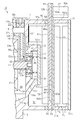
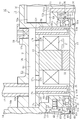
- Sectional drawing which expands and shows the 1st rolling bearing side in an electric supercharger.
- Sectional drawing which expands and shows the 2nd rolling bearing side in an electric supercharger.
- Sectional drawing which expands and shows a part of electric supercharger.
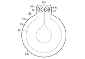
- the front view of the base part of a heat exchanger The front view which looked at the heat exchanger from the lid side.
- Sectional drawing which expands and shows a part of electric supercharger in another embodiment.
- Sectional drawing which expands and shows a part of electric supercharger in another embodiment.
- the electric supercharger of the present embodiment is installed in the engine room of an automobile and is used to compress and supply air as a fluid to the engine.
- the housing 11 of the electric supercharger 10 has a motor housing 12, a compressor housing 13, a seal plate 14, and a cover 15.
- the motor housing 12, the compressor housing 13, the seal plate 14, and the cover 15 are made of metal, for example, aluminum.
- the motor housing 12 has a bottomed cylindrical shape having a disk-shaped bottom wall 12a and a peripheral wall 12b extending in a cylindrical shape from the outer peripheral portion of the bottom wall 12a.
- a through hole 12h is formed in the center of the bottom wall 12a.
- the cover 15 has a flat plate shape and closes the through hole 12h by being attached to the outer surface 121a of the bottom wall 12a by a bolt (not shown).
- the seal plate 14 has a disc shape and is connected to the end of the peripheral wall 12b of the motor housing 12 opposite to the bottom wall 12a.
- the seal plate 14 has a cylindrical fitting portion 14f protruding from the center of the end surface 14a of the seal plate 14 on the motor housing 12 side.
- the seal plate 14 is connected to the motor housing 12 in a state in which the fitting portion 14f is fitted into the opening 12c on the opposite side of the bottom wall 12a of the motor housing 12.
- the fitting portion 14f closes the opening 12c of the motor housing 12.
- a shaft insertion hole 14h is formed in the fitting portion 14f of the seal plate 14.
- An annular engaging portion 14e projects from a portion of the inner peripheral surface of the shaft insertion hole 14h farthest from the bottom wall 12a of the motor housing 12.
- the compressor housing 13 is connected to the seal plate 14 on the side opposite to the motor housing 12.
- the compressor housing 13 has a substantially disc-shaped bottom wall 13a and a peripheral wall 13b extending from the outer peripheral portion of the bottom wall 13a in a tubular shape.
- the opening on the side of the peripheral wall 13b opposite to the bottom wall 13a is closed by a seal plate 14.
- the electric supercharger 10 includes a rotating shaft 17 rotatably supported by a housing 11.
- One end of the rotary shaft 17 penetrates the shaft insertion hole 14h and projects into the compressor housing 13.
- An impeller 18 is connected to one end of the rotary shaft 17. Therefore, the impeller 18 is connected to the axial end of the rotary shaft 17.
- the other end of the rotating shaft 17 is located inside the through hole 12h.
- the electric motor 19 for rotating the rotating shaft 17 is housed in the motor housing 12. Therefore, the motor housing 12 houses the electric motor 19.
- the electric motor 19 is housed in a motor chamber 20 which is a space surrounded by the bottom wall 12 a and the peripheral wall 12 b of the motor housing 12 and the seal plate 14.
- the electric motor 19 includes a tubular stator 21 and a rotor 22 arranged inside the stator 21.
- a coil 23 is wound around the stator 21.
- the rotor 22 rotates integrally with the rotating shaft 17 by supplying a current to the coil 23.
- the stator 21 includes a stator core 21a fixed to the inner peripheral surface of the peripheral wall 12b of the motor housing 12, a first coil end 23a and a second coil end 23a protruding from both end surfaces of the stator core 21a that are located in the axial direction of the rotating shaft 17. 23b.
- the first coil end 23a projects from an end surface of the stator core 21a located on the seal plate 14 side in the axial direction of the rotating shaft 17.
- the second coil end 23b projects from the end surface of the stator core 21a located on the bottom wall 12a side of the motor housing 12 in the axial direction of the rotating shaft 17.
- the first coil end 23 a and the second coil end 23 b are a part of the coil 23.
- the electric supercharger 10 includes a first rolling bearing 31 that rotatably supports a portion of the rotary shaft 17 near the impeller 18 in the axial direction of the rotary shaft 17.
- the first rolling bearing 31 is arranged between the outer peripheral surface of the rotating shaft 17 and the inner peripheral surface of the shaft insertion hole 14h. A portion of the rotary shaft 17 near the impeller 18 is rotatably supported by the seal plate 14 via a first rolling bearing 31.
- the first rolling bearing 31 includes a first inner ring 31a fixed to the outer peripheral surface of the rotary shaft 17, a first outer ring 31b arranged outside the first inner ring 31a, a first inner ring 31a and a first outer ring 31b.
- An angular contact ball bearing having a plurality of spherical first rolling elements 31c arranged between the two.
- the first inner ring 31 a is press fitted onto the outer peripheral surface of the rotating shaft 17.
- the first outer ring 31b is press fitted into the inner peripheral surface of the shaft insertion hole 14h.
- the electric supercharger 10 includes a second rolling bearing 32 that rotatably supports a portion of the rotating shaft 17 that is farther from the impeller 18 than the first rolling bearing 31 in the axial direction of the rotating shaft 17. ing.
- a cylindrical bearing holding sleeve 33 made of iron is press-fitted to the inner peripheral surface of the through hole 12h.
- the second rolling bearing 32 is arranged between the outer peripheral surface of the rotating shaft 17 and the inner peripheral surface of the bearing holding sleeve 33.
- the other end of the rotating shaft 17 is rotatably supported by the bottom wall 12 a of the motor housing 12 via the second rolling bearing 32 and the bearing holding sleeve 33.
- the second rolling bearing 32 is a bearing that rotatably supports the end of the rotating shaft 17, which is a portion opposite to the impeller 18, with respect to the housing 11. Therefore, the rotary shaft 17 is rotatably supported by the housing 11 via the first rolling bearing 31 and the second rolling bearing 32.
- the through hole 12h is provided in the bottom wall 12a of the motor housing 12 and functions as a bearing accommodating portion that accommodates the second rolling bearing 32.
- the bottom wall 12a of the motor housing 12 functions as a bearing holding wall having a bearing housing.
- the second rolling bearing 32 includes a second inner ring 32a fixed to the outer peripheral surface of the rotating shaft 17, a second outer ring 32b arranged outside the second inner ring 32a, a second inner ring 32a and a second outer ring 32b.
- An angular contact ball bearing having a plurality of spherical second rolling elements 32c arranged between the two.
- the second inner ring 32a is press fitted into the outer peripheral surface of the rotary shaft 17.
- the second outer ring 32b is fitted into the inner peripheral surface of the bearing holding sleeve 33 with a clearance.
- a housing chamber 34 is provided between the bearing holding sleeve 33 and the cover 15 in the axial direction of the rotary shaft 17.
- a washer 35 is provided inside the bearing holding sleeve 33 so as to come into contact with the end surface of the second outer ring 32b on the accommodation chamber 34 side.
- a preload spring 36 is housed in the housing chamber 34. The preload spring 36 is interposed between the washer 35 and the cover 15.
- the one end of the preload spring 36 contacts the cover 15, and the other end of the preload spring 36 contacts the washer 35.
- the preload spring 36 is arranged between the cover 15 and the washer 35 while being compressed in the axial direction of the rotary shaft 17. Therefore, the cover 15 holds the preload spring 36. Then, the preload spring 36 urges the second rolling bearing 32 through the washer 35 in the axial direction of the rotating shaft 17 by the force of returning to the original shape of the compressed preload spring 36.
- the biasing force of the preload spring 36 is transmitted to the second outer ring 32b via the washer 35, and the biasing force transmitted to the second outer ring 32b is transmitted to the second inner ring 32a via the second rolling element 32c.
- the second inner ring 32a is pressed toward the impeller 18 in the axial direction of the rotating shaft 17.
- the biasing force of the preload spring 36 is transmitted from the second inner ring 32a to the rotating shaft 17, and the rotating shaft 17 tends to move toward the impeller 18 in the axial direction of the rotating shaft 17.
- the rotating shaft 17 is in contact with the first inner ring 31a of the first rolling bearing 31, and the first rolling element 31c is pressed against the rotating shaft 17 by the first inner ring 31a toward the impeller 18 in the axial direction, and The outer ring 31b is pressed. Then, the first outer ring 31b is pressed against the first rolling element 31c so as to be in contact with the engaging portion 14e of the shaft insertion hole 14h.
- the compressor housing 13 is compressed by the suction port 13c through which air (fresh air) is suctioned, an impeller chamber 13d that communicates with the suction port 13c and that houses an impeller 18, and the impeller 18. It has a discharge chamber 13e from which air is discharged, and a diffuser flow path 13f that connects the impeller chamber 13d and the discharge chamber 13e.
- the impeller 18 rotates, and the centrifugal force of the rotating impeller 18 gives velocity energy to the air sucked from the suction port 13c.
- the air that has been supplied with velocity energy and has increased in velocity is decelerated in the diffuser flow path 13f provided at the outlet of the impeller 18, and the velocity energy of the air is converted into pressure energy. Then, the high-pressure air is discharged from the discharge chamber 13e and supplied to an engine (not shown).
- a circular hole-shaped recess 14c is formed on the end surface 14b of the seal plate 14 on the compressor housing 13 side.
- the inside of the recess 14c communicates with the shaft insertion hole 14h.
- a disc-shaped retainer 41 is fitted in the recess 14c.
- the retainer 41 is attached to the seal plate 14 by a bolt 42 penetrating the retainer 41 being screwed into the bottom surface of the recess 14c.
- the retainer 41 has a retainer insertion hole 41h through which the rotary shaft 17 is inserted.
- a cylindrical seal collar 43 made of iron is arranged between the outer peripheral surface of the rotary shaft 17 and the inner peripheral surface of the retainer insertion hole 41h.
- the seal collar 43 is attached to the outer peripheral surface of the rotary shaft 17 in a state of being sandwiched between a step portion formed on the outer peripheral surface of the rotary shaft 17 and the back surface of the impeller 18. Therefore, the seal collar 43 rotates integrally with the rotating shaft 17.
- An annular mounting groove 43a is formed on the outer peripheral surface of the seal collar 43.
- a seal ring 44 is mounted in the mounting groove 43a.
- the seal ring 44 has a non-annular shape with a notch formed in a part thereof. Then, the seal ring 44 is accommodated in the mounting groove 43a in a state of being reduced in diameter by the notch, and the seal ring 44 returns to its original shape in the mounting groove 43a, so that the outer peripheral surface of the seal ring 44 is inserted through the retainer. It is in contact with the inner peripheral surface of the hole 41h. Thereby, the seal ring 44 seals between the mounting groove 43a and the retainer insertion hole 41h.
- a recess 41a is formed on the end surface of the retainer 41 on the bottom surface side of the recess 14c and around the retainer insertion hole 41h.
- An annular flange 43f projects from an end of the outer peripheral surface of the seal collar 43 opposite to the impeller 18.
- the flange portion 43f is located inside the recess 41a of the retainer 41.
- the flange portion 43f cooperates with the seal ring 44 to function as a labyrinth seal.
- the seal plate 14 has a plate-shaped deflector portion 14g protruding inward in the radial direction of the rotary shaft 17 from a part of the inner peripheral surface of the engaging portion 14e.
- the seal plate 14 has a motor chamber 20 and a portion located inside the engagement portion 14e in the shaft insertion hole 14h and on the opposite side in the radial direction of the rotary shaft 17 with respect to the deflector portion 14g.
- a first oil discharge passage 14k that communicates is formed.
- the bottom wall 12 a of the motor housing 12 is formed with a second oil discharge passage 12 k that connects the housing chamber 34 and the motor chamber 20. ..
- an oil passage 50 is formed in a part of the peripheral wall 12b of the motor housing 12.
- the oil passage 50 has a main passage 51.
- the main flow path 51 is bored by, for example, a drill from the end surface of the peripheral wall 12b of the motor housing 12 on the opening 12c side.
- the main passage 51 extends in the axial direction of the rotary shaft 17 from the end surface of the peripheral wall 12b of the motor housing 12 on the side of the opening 12c toward the bottom wall 12a.
- the opening on the end face side of the peripheral wall 12b of the motor housing 12 on the side of the opening 12c in the main passage 51 is closed by the seal plate 14.
- the end of the main passage 51 on the side of the bottom wall 12a of the motor housing 12 is positioned so as to overlap the space between the electric motor 19 and the second rolling bearing 32 in the axial direction of the rotary shaft 17 in the radial direction of the rotary shaft 17. It is in.
- a first pipe mounting hole 12e and a second pipe mounting hole 12f are formed in the peripheral wall 12b of the motor housing 12.
- the first pipe mounting hole 12e and the second pipe mounting hole 12f are circular holes.
- One end of the first pipe mounting hole 12e opens in the main flow path 51 near the end on the seal plate 14 side.
- the other end of the first pipe mounting hole 12e is provided on the inner peripheral surface of the peripheral wall 12b of the motor housing 12 with respect to the space between the electric motor 19 and the first rolling bearing 31 in the axial direction of the rotating shaft 17 with respect to the rotating shaft 17.
- the holes are opened at positions overlapping in the radial direction.
- One end of the second pipe mounting hole 12f is opened in the main passage 51 near the end of the motor housing 12 on the side of the bottom wall 12a.
- the other end of the second pipe mounting hole 12f is provided on the inner peripheral surface of the peripheral wall 12b of the motor housing 12 with respect to the space between the electric motor 19 and the second rolling bearing 32 in the axial direction of the rotating shaft 17 with respect to the rotating shaft 17.
- the holes are opened at positions overlapping in the radial direction.
- a first connection hole 12m and a second connection hole 12n are formed on the peripheral wall 12b of the motor housing 12.
- the first connecting hole 12m and the second connecting hole 12n are circular hole-shaped female screw holes.
- the first connection hole 12m is arranged in the peripheral wall 12b of the motor housing 12 at a position overlapping the first pipe mounting hole 12e in the radial direction of the rotating shaft 17.
- One end of the first connection hole 12m is open to the outer peripheral surface of the peripheral wall 12b of the motor housing 12.
- the other end of the first connection hole 12m opens into the main flow path 51.
- the first connection hole 12m extends in the radial direction of the rotary shaft 17.
- the diameter of the first connection hole 12m is larger than the diameter of the first pipe mounting hole 12e.
- the second connection hole 12n is arranged in the peripheral wall 12b of the motor housing 12 at a position overlapping the second pipe mounting hole 12f in the radial direction of the rotating shaft 17.
- One end of the second connection hole 12n opens to the outer peripheral surface of the peripheral wall 12b of the motor housing 12.
- the other end of the second connection hole 12n opens into the main flow channel 51.
- the second connection hole 12n extends in the radial direction of the rotating shaft 17.
- the hole diameter of the second connection hole 12n is larger than the hole diameter of the second pipe mounting hole 12f.
- the first oil supply pipe 55 is attached to the first pipe attachment hole 12e.
- the first oil supply pipe 55 extends linearly.
- the first oil supply pipe 55 is attached to the peripheral wall 12b of the motor housing 12 by passing through the first connection hole 12m and the main flow passage 51 and having one end press-fitted into the first pipe attachment hole 12e.
- the other end of the first oil supply pipe 55 passes through the first pipe mounting hole 12e and projects between the electric motor 19 and the first rolling bearing 31 in the axial direction of the rotary shaft 17 in the motor chamber 20. ing. Therefore, the first oil supply pipe 55 is arranged between the electric motor 19 and the seal plate 14 in the axial direction of the rotary shaft 17.
- the first oil supply pipe 55 extends in the radial direction of the rotary shaft 17.
- the first oil supply pipe 55 has a first supply passage 55a extending inside the first oil supply pipe 55 in the axial direction of the first oil supply pipe 55. One end of the first supply passage 55a communicates with the main passage 51. The first supply passage 55a extends in the radial direction of the rotating shaft 17. In addition, the first oil supply pipe 55 communicates with the first supply passage 55a and has a first ejection hole 55b for ejecting oil toward between the first inner ring 31a and the first outer ring 31b of the first rolling bearing 31. Have The first ejection hole 55b extends in the axial direction of the rotary shaft 17. One end of the first ejection hole 55b communicates with the end of the first supply passage 55a on the opposite side of the main flow passage 51.
- the other end of the first ejection hole 55b opens to the outer peripheral surface of the other end of the first oil supply pipe 55.
- the first ejection hole 55b faces a part between the first inner ring 31a and the first outer ring 31b in the axial direction of the rotating shaft 17.
- the flow passage cross-sectional area of the first ejection hole 55b is smaller than the flow passage cross-sectional area of the first supply passage 55a.
- a second oil supply pipe 56 is attached to the second pipe attachment hole 12f.
- the second oil supply pipe 56 extends linearly.
- the second oil supply pipe 56 is attached to the peripheral wall 12b of the motor housing 12 by passing through the second connection hole 12n and the main flow path 51, and having one end press-fitted into the second pipe attachment hole 12f.
- the other end of the second oil supply pipe 56 passes through the second pipe mounting hole 12f and projects in the motor chamber 20 between the electric motor 19 and the second rolling bearing 32 in the axial direction of the rotating shaft 17. ing. Therefore, the second oil supply pipe 56 is arranged between the electric motor 19 and the bottom wall 12 a of the motor housing 12 in the axial direction of the rotary shaft 17.
- the second oil supply pipe 56 extends in the radial direction of the rotating shaft 17.
- the second oil supply pipe 56 has a second supply passage 56 a that extends inside the second oil supply pipe 56 in the axial direction of the second oil supply pipe 56.
- One end of the second supply passage 56a communicates with the main flow passage 51.
- the second supply passage 56a extends in the radial direction of the rotary shaft 17.
- the second oil supply pipe 56 communicates with the second supply passage 56a and has a second ejection hole 56b for ejecting oil toward between the second inner ring 32a and the second outer ring 32b of the second rolling bearing 32.
- Have The second ejection hole 56b extends in the axial direction of the rotary shaft 17.
- One end of the second ejection hole 56b communicates with the end of the second supply passage 56a on the opposite side of the main flow passage 51.
- the other end of the second ejection hole 56b opens to the outer peripheral surface of the other end of the second oil supply pipe 56.
- the second ejection hole 56b faces a part between the second inner ring 32a and the second outer ring 32b in the axial direction of the rotating shaft 17.
- the flow passage cross-sectional area of the second ejection hole 56b is smaller than the flow passage cross-sectional area of the second supply passage 56a.
- the oil passage 50 also has a first oil supply hole 57a and a second oil supply hole 57b formed in the peripheral wall 12b of the motor housing 12.
- One ends of the first oil supply hole 57a and the second oil supply hole 57b open in the main flow path 51, and between the first pipe mounting hole 12e and the second pipe mounting hole 12f in the axial direction of the rotating shaft 17. It is located in.
- the other end of the first oil supply hole 57a is opened on the inner peripheral surface of the peripheral wall 12b of the motor housing 12 at a position overlapping the first coil end 23a in the radial direction of the rotating shaft 17.
- the other end of the second oil supply hole 57b is opened on the inner peripheral surface of the peripheral wall 12b of the motor housing 12 at a position overlapping the second coil end 23b in the radial direction of the rotating shaft 17.
- An oil introduction pipe 58 is attached to the first connection hole 12m.
- the oil introduction pipe 58 a part of the oil stored in the oil pan of the engine flows. Then, the oil flowing through the oil introduction pipe 58 is supplied into the main flow path 51.
- a closing member 59 is attached to the second connection hole 12n. The closing member 59 is attached to the second connection hole 12n after being attached to the second pipe attachment hole 12f in the second oil supply pipe 56.
- a discharge passage 20k for discharging the oil in the motor chamber 20 to the outside of the housing 11 is formed in a portion of the peripheral wall 12b of the motor housing 12 located on the opposite side of the main flow passage 51.
- the main flow path 51 is located above the rotation shaft 17 in the gravity direction, and the discharge passage 20k and the second oil discharge passage 12k are below the rotation shaft 17 in the gravity direction. It is installed in the engine room to be located at.
- the deflector portion 14g is located closer to the main flow path 51 in the radial direction of the rotary shaft 17, and the first oil drain passage 14k is in the radial direction of the rotary shaft 17. It is attached to the motor housing 12 so as to be located closer to 20 k. Therefore, the deflector portion 14g is located above the rotating shaft 17 in the direction of gravity, and the first oil drain passage 14k is located below the rotating shaft 17 in the direction of gravity.
- the bottom wall 12a of the motor housing 12 has a cylindrical extending portion 60 that projects to the opposite side of the outer wall 121a of the bottom wall 12a from the peripheral wall 12b.
- the extending portion 60 extends in the axial direction of the rotating shaft 17 from the outer peripheral portion of the bottom wall 12a.
- the electric supercharger 10 is equipped with a heat exchanger 61.
- the heat exchanger 61 is attached to the extension portion 60, which is a part of the bottom wall 12a, by a bolt (not shown). Therefore, the heat exchanger 61 is attached to the housing 11.
- the extended portion 60 projects from the outer surface 121a of the bottom wall 12a of the motor housing 12 and extends toward the heat exchanger 61.
- the heat exchanger 61 has a flat base portion 62 and a flat lid portion 63 attached to the base portion 62.
- An annular heat insulating material 64 is interposed between the heat exchanger 61 and the end surface 60a of the extended portion 60 on the heat exchanger 61 side. Therefore, the heat insulating material 64 is interposed between the bottom wall 12 a of the motor housing 12 and the heat exchanger 61.
- the base portion 62 has a disk-shaped base portion main body 62a and a flat plate-shaped base portion protrusion portion 62b protruding from a part of the outer peripheral surface of the base portion main body 62a.
- One end surface of the base body 62a and one end surface of the base protrusion 62b are located on the same plane.
- the other end surface of the base body 62a and the other end surface of the base protrusion 62b are located on the same plane.
- the base 62 has a waterway groove 65.
- the water channel groove 65 has one end located on the base protruding portion 62b and extends from the base protruding portion 62b toward the center of one end surface of the base body 62a. Further, the water channel groove 65 extends substantially once around the center of one end face of the base body 62a in the circumferential direction of the base body 62a, then extends toward the base projecting portion 62b, and the other end is located at the base projecting portion 62b.
- the base body 62a has one end face and the base protrusion 62b has one end face that is recessed.
- the lid 63 has a disc-shaped lid main body 63a and a flat-plate-shaped lid projection 63b protruding from a part of the outer peripheral surface of the lid main body 63a.
- the outer diameter of the lid body 63a is the same as the outer diameter of the base body 62a.
- the lid protruding portion 63b has the same shape as the base protruding portion 62b when seen in a plan view.
- One end surface of the lid portion main body 63a and one end surface of the lid portion protruding portion 63b are located on the same plane. Further, the other end surface of the lid main body 63a and the other end surface of the lid projection 63b are located on the same plane.
- a cylindrical water supply cylinder 63c and a water discharge cylinder 63d project from one end surface of the lid projecting portion 63b.
- the lid 63 has a water supply passage 66 that penetrates the inside of the water supply cylinder 63c and the lid projection 63b, and a water discharge passage 67 that penetrates the inside of the water discharge cylinder 63d and the lid projection 63b.
- Have One end of the water supply passage 66 is open at the end of the water supply cylinder 63c on the opposite side of the lid projection 63b.
- the other end of the water supply passage 66 is open to the other end surface of the lid protrusion 63b.
- One end of the water discharge path 67 is open to the end of the water discharge cylinder 63d on the side opposite to the lid protrusion 63b.
- the other end of the water discharge path 67 is open to the other end surface of the lid protrusion 63b.
- the base 62 and the lid 63 are in surface contact with one end surface of the base body 62a and the other end surface of the lid body 63a, and are in surface contact with one end surface of the base protrusion 62b and the other end surface of the lid protrusion 63b. In this state, they are joined together. Then, one end of the water channel groove 65 communicates with the other end of the water supply channel 66, and the other end of the water channel channel 65 communicates with the other end of the water discharge channel 67. A portion of the water channel groove 65 excluding a portion facing the water supply channel 66 and the water discharge channel 67 is closed by a lid 63.
- a cooling water flow path 68 through which cooling water flows is formed by being partitioned by the water channel groove 65 and the lid 63. Therefore, the heat exchanger 61 has the cooling water flow path 68.
- the cooling water supplied from the water supply passage 66 flows into the cooling water passage 68. Then, the cooling water that has passed through the cooling water flow path 68 is discharged to the outside of the heat exchanger 61 via the water discharge path 67.
- the heat exchanger 61 is attached to the bottom wall 12a of the motor housing 12 so that the other end surface of the base body 62a and the other end surface of the base protrusion 62b are located on the motor housing 12 side. There is. Therefore, the other end surface of the base body 62a and the other end surface of the base protrusion 62b form a first surface 61a that is a surface of the heat exchanger 61 located on the motor housing 12 side. Further, one end surface of the lid main body 63a and one end surface of the lid projection 63b form a second surface 61b which is a surface of the heat exchanger 61 located on the side opposite to the motor housing 12.
- the first surface 61a and the second surface 61b of the heat exchanger 61 extend in a direction orthogonal to the axial direction of the rotating shaft 17.
- the heat exchanger 61 is attached to the bottom wall 12a of the motor housing 12 with the first surface 61a positioned closer to the motor housing 12 side than the second surface 61b.
- An annular housing recess 69 is formed on the outer surface 121a of the bottom wall 12a of the motor housing 12.
- the housing recess 69 extends annularly around the through hole 12h.
- a substrate housing chamber 70 is formed between the bottom wall 12 a of the motor housing 12 and the heat exchanger 61.
- the substrate housing chamber 70 is partitioned by the inner peripheral surface of the extending portion 60, the inner surface of the housing recess 69, the outer surface of the cover 15, and the first surface 61 a of the heat exchanger 61.
- the electric supercharger 10 includes an inverter circuit 71 that drives the electric motor 19.
- the inverter circuit 71 has a capacitor board 72, a power board 73, and a control board 74.
- a capacitor 72a is mounted on the capacitor board 72.
- a switching element such as an IGBT (power switching element) is mounted on the power board 73.
- a control circuit for controlling the switching operation of the switching element of the power board 73 is mounted.
- the capacitor substrate 72 is accommodated in the substrate accommodating chamber 70 while being attached to the first surface 61 a of the heat exchanger 61. Therefore, the capacitor substrate 72 is thermally coupled to the first surface 61a of the heat exchanger 61.
- the capacitor 72 a is accommodated in the accommodating recess 69 and arranged on the outer peripheral portion of the second rolling bearing 32.
- the capacitor substrate 72 extends in a direction orthogonal to the axial direction of the rotating shaft 17.
- An inverter case 75 accommodating the power board 73 and the control board 74 is attached to the second surface 61b of the heat exchanger 61.
- the inverter case 75 has a bottomed cylindrical case body 75a and a flat plate-shaped cover member 75b that closes the opening of the case body 75a.
- the case main body 75a has a case bottom wall 751a and a case peripheral wall 752a extending in a tubular shape from the outer peripheral portion of the case bottom wall 751a.
- the inverter case 75 is attached to the second surface 61b of the heat exchanger 61 by a bolt (not shown) with the outer surface of the case bottom wall 751a of the case body 75a being in surface contact with the second surface 61b of the heat exchanger 61. It is installed.
- the case bottom wall 751a is the first wall portion of the inverter case 75 on the side closer to the second surface 61b of the heat exchanger 61.
- the cover member 75b is a second wall portion of the inverter case 75 on the side far from the second surface 61b of the heat exchanger 61.
- the power board 73 is attached to the inner surface of the case bottom wall 751a of the case body 75a while being in contact with the inner surface of the case bottom wall 751a of the case body 75a. Therefore, in the inverter case 75, the power board 73 is disposed inside the inverter case 75 in a state of being in contact with the inner surface of the case bottom wall 751a that is the first wall portion on the side closer to the second surface 61b of the heat exchanger 61. There is.
- the power board 73 is thermally coupled to the second surface 61b of the heat exchanger 61 via the case bottom wall 751a of the case body 75a of the inverter case 75.
- the power board 73 extends in a direction orthogonal to the axial direction of the rotating shaft 17.
- the control board 74 is attached to the inner surface of the cover member 75b while being in contact with the inner surface of the cover member 75b. Therefore, the control board 74 is arranged in the inverter case 75 in a state of being in contact with the inner surface of the cover member 75b, which is the second wall portion on the side far from the second surface 61b of the heat exchanger 61, in the inverter case 75. ..
- the control board 74 extends in a direction orthogonal to the axial direction of the rotating shaft 17.
- the power board 73 and the control board 74 are electrically connected by a connection line (not shown).
- the electric supercharger 10 of the present embodiment has a configuration in which the impeller 18, the electric motor 19, and the inverter circuit 71 are arranged in this order in the axial direction of the rotary shaft 17.
- the cooling water flow path 68 is positioned so as to overlap the capacitor board 72, the power board 73, and the control board 74 in the axial direction of the rotating shaft 17.
- the cooling water flowing through the cooling water flow path 68 can exchange heat with the heat generated from the capacitor substrate 72, the power substrate 73, and the control substrate 74. Therefore, cooling water for cooling the inverter circuit 71 flows through the cooling water passage 68.
- the oil supplied to the main flow path 51 from the oil introduction pipe 58 and filled in the main flow path 51 is the first supply passage 55 a of the first oil supply pipe 55 and the second oil supply pipe 56.
- the two flow paths 56a respectively flow into.
- the oil flowing into the first supply passage 55a and the second supply passage 56a respectively passes through the first supply passage 55a and the second supply passage 56a.
- the oil that has passed through the first supply passage 55a is ejected from the first ejection hole 55b toward between the first inner ring 31a and the first outer ring 31b.
- the oil is squeezed when passing through the first ejection hole 55b and the first inner ring 31a.
- the first outer ring 31b is vigorously ejected from the first ejection hole 55b.
- the oil that has passed through the second supply passage 56a is ejected from the second ejection hole 56b toward the second inner ring 32a and the second outer ring 32b.
- the oil is squeezed when passing through the second ejection hole 56b and the second inner ring 32a.
- the second outer ring 32b is vigorously ejected from the second ejection hole 56b.
- the oil filled in the main flow path 51 passes through the first oil supply hole 57a and is supplied to the first coil end 23a. Further, the oil filled in the main flow path 51 passes through the second oil supply hole 57b and is supplied to the second coil end 23b. As a result, the first coil end 23a and the second coil end 23b are cooled, and as a result, the electric motor 19 is cooled. Therefore, the oil passage 50 is formed in the housing 11 and the oil for cooling the electric motor 19 flows. The oil that has contributed to the cooling of the first coil end 23a and the second coil end 23b is discharged to the outside of the housing 11 through the discharge passage 20k and is returned to the oil pan of the engine.
- the heat generated in the capacitor substrate 72 and the cooling water flowing in the cooling water passage 68 are exchanged via the first surface 61 a of the heat exchanger 61, whereby the heat of the capacitor substrate 72 is reduced. Is dissipated.
- the capacitor substrate 72 is cooled by the cooling water flowing through the cooling water passage 68 via the first surface 61 a of the heat exchanger 61.
- the heat generated from the power board 73 and the cooling water flowing through the cooling water flow path 68 are exchanged through the case body 75a of the inverter case 75 and the second surface 61b of the heat exchanger 61, whereby the power board The heat of 73 is radiated.
- the power board 73 is cooled by the cooling water flowing through the cooling water flow path 68 via the case body 75 a of the inverter case 75 and the second surface 61 b of the heat exchanger 61. Further, heat generated from the control board 74 and cooling water flowing through the cooling water flow path 68 are exchanged through the cover member 75b of the inverter case 75, the case body 75a, and the second surface 61b of the heat exchanger 61. As a result, the heat of the control board 74 is radiated. As a result, the control board 74 is cooled by the cooling water flowing through the cooling water passage 68 via the cover member 75b of the inverter case 75, the case body 75a, and the second surface 61b of the heat exchanger 61.
- the electric supercharger 10 further includes a heat exchanger 61 mounted on the motor housing 12 and having a cooling water flow path 68.
- the condenser board 72 is cooled by the cooling water flowing through the cooling water passage 68 through the first surface 61a of the heat exchanger 61
- the power board 73 is cooled by the cooling water flow through the second surface 61b of the heat exchanger 61. It is cooled by the cooling water flowing through the path 68.
- the capacitor substrate 72 and the power substrate 73 are thermally coupled to only one of the first surface 61a and the second surface 61b of the heat exchanger 61, and only one of the first surface 61a and the second surface 61b is interposed.
- the condenser substrate 72 and the power substrate 73 are cooled by the cooling water flowing through the cooling water passage 68. Compared to this case, the capacitor substrate 72 and the power substrate 73 can be cooled efficiently.
- the power board 73 is arranged in the inverter case 75 in a state of being in contact with the inner surface of the case bottom wall 751a that is the first wall portion on the side closer to the second surface 61b of the heat exchanger 61.
- the control board 74 is arranged in the inverter case 75 in a state of being in contact with the inner surface of the cover member 75b which is the second wall portion on the side far from the second surface 61b of the heat exchanger 61.
- the power board 73 and the control board 74 are arranged in the inverter case 75 in a state of being in contact with the inner surface of the case bottom wall 751 a of the inverter case 75.
- the power board 73 that generates more heat than the control board 74 can be efficiently cooled by the cooling water flowing through the cooling water flow path 68 via the inverter case 75 and the second surface 61b of the heat exchanger 61. ..
- the capacitor 72 a mounted on the capacitor substrate 72 is housed in the housing recess 69 and arranged on the outer peripheral portion of the second rolling bearing 32. Therefore, even if the heat exchanger 61 is attached to the bottom wall 12a of the motor housing 12 with the first surface 61a positioned closer to the motor housing 12 side than the second surface 61b, the condenser 72a is accommodated. Since it is housed in the recess 69 and arranged on the outer peripheral portion of the second rolling bearing 32, it is possible to reduce the axial size of the rotary shaft 17 in the electric supercharger 10.
- a heat insulating material 64 is interposed between the bottom wall 12 a of the motor housing 12 and the heat exchanger 61. According to this, the heat transfer between the motor housing 12 and the heat exchanger 61 can be suppressed by the heat insulating material 64, so that the heat of the motor housing 12 is transferred to the heat exchanger 61 and the cooling water passage 68 flows. It is possible to prevent the temperature of the flowing cooling water from rising. Further, the electric motor 19 can be efficiently cooled with oil and the inverter circuit 71 can be efficiently cooled with cooling water.
- the operating time of the electric supercharger 10 can be extended and the output of the electric supercharger 10 can be increased. Can be improved.
- the heat insulating material 64 may not be interposed between the bottom wall 12a of the motor housing 12 and the heat exchanger 61.
- a cutout portion 60b may be formed on the end surface 60a of the extension portion 60 on the heat exchanger 61 side.
- the cutout portion 60b is an annular inner peripheral surface 601b that is continuous with the end surface 60a of the extending portion 60 and extends in the axial direction of the extending portion 60, and a side opposite to the end surface 60a of the extending portion 60 on the inner peripheral surface 601b.
- an annular bottom surface 602b that extends in the radial direction of the extending portion 60 from the end edge of and is continuous with the inner peripheral surface of the extending portion 60.
- the end surface 60a of the extending portion 60 is flat and extends in the radial direction of the rotating shaft 17.
- the end surface 60a of the extended portion 60 is in surface contact with the first surface 61a of the heat exchanger 61.
- the bottom surface 602b of the cutout portion 60b is flat and parallel to the end surface 60a of the extension portion 60.
- the area of the end surface 60a of the extending portion 60 is smaller than the cross-sectional area of the extending portion 60 that passes through the bottom surface 602b of the cutout portion 60b in the radial direction of the rotating shaft 17.
- the contact area between the motor housing 12 and the heat exchanger 61 is made smaller than in the case where the cutout portion 60b is not formed in the end surface 60a of the extension portion 60 on the heat exchanger 61 side. be able to. Therefore, since heat transfer between the motor housing 12 and the heat exchanger 61 can be suppressed, the heat of the motor housing 12 is transferred to the heat exchanger 61 and the temperature of the cooling water flowing through the cooling water passage 68 rises. It can be suppressed. Further, the electric motor 19 can be efficiently cooled with oil and the inverter circuit 71 can be efficiently cooled with cooling water.
- the motor housing 12 may be further provided with a cooling water jacket 76 that branches from the cooling water flow path 68 and is adjacent to the oil path 50.
- the cooling water flowing through the cooling water passage 68 flows into the cooling water jacket 76.
- the cooling water flowing through the cooling water jacket 76 and the oil flowing through the oil passage 50 can exchange heat with each other via the motor housing 12.
- the cooling water jacket 76 is formed inside the bottom wall 12 a and the peripheral wall 12 b of the motor housing 12.
- the cooling water jacket 76 extends in the axial direction of the rotating shaft 17.
- One end of the cooling water jacket 76 is located inside the peripheral wall 12b of the motor housing 12, and the other end is opened at a portion of the bottom wall 12a of the motor housing 12 that contacts the heat exchanger 61.
- a part of the cooling water jacket 76 is adjacent to the main passage 51 in the circumferential direction of the motor housing 12. According to this, since the oil flowing through the oil passage 50 can be cooled by the cooling water flowing through the cooling water jacket 76, the cooling performance of the electric motor 19 by the oil can be further improved.
- the power substrate 73 may be thermally coupled to the first surface 61a of the heat exchanger 61, and the capacitor substrate 72 may be thermally coupled to the second surface 61b of the heat exchanger 61. ..
- either the capacitor board 72 or the power board 73 is thermally coupled to the first surface 61a of the heat exchanger 61, and the second surface 61b of the heat exchanger 61 is connected to the capacitor board 72 or the power board 73. It suffices if either one of the substrates 73 is thermally coupled.
- the capacitor substrate 72 and the power substrate 73 may be thermally coupled to only one of the first surface 61a and the second surface 61b of the heat exchanger 61. Then, the condenser board 72 and the power board 73 may be cooled by the cooling water flowing through the cooling water passage 68 through only one of the first surface 61a and the second surface 61b of the heat exchanger 61.
- the power board 73 and the control board 74 are in contact with the inner surface of the case bottom wall 751a, which is the first wall portion of the inverter case 75 on the side closer to the second surface 61b. May be arranged in the inverter case 75.
- the annular housing recess 69 may not be formed on the outer surface 121a of the bottom wall 12a of the motor housing 12. Therefore, the electric supercharger 10 may be configured such that the capacitor 72a mounted on the capacitor substrate 72 is not housed in the housing recess 69 and is not arranged on the outer peripheral portion of the second rolling bearing 32. .
- the electric supercharger 10 may have a configuration in which the heat insulating material 64 is not interposed between the heat exchanger 61 and the end surface 60a of the extension portion 60 on the heat exchanger 61 side.
- the heat exchanger 61 is mounted on the motor housing 12 so that the first surface 61a and the second surface 61b of the heat exchanger 61 extend in a direction oblique to the axial direction of the rotating shaft 17. It may be attached.
- the capacitor substrate 72 and the power substrate 73 may extend in a direction oblique to the axial direction of the rotating shaft 17.
- one of the first oil supply hole 57a and the second oil supply hole 57b may not be formed in the peripheral wall 12b of the motor housing 12.
- the electric supercharger 10 may not have the second oil supply pipe 56.
- a passage for supplying the oil in the main passage 51 to the second rolling bearing 32 may be formed in the bottom wall 12a of the motor housing 12.
- the electric supercharger 10 may not have the first oil supply pipe 55 and the second oil supply pipe 56.
- the oil passage 50 may be a passage formed in the housing 11 and through which oil for cooling the electric motor 19 flows.
- the lid 63 and the inverter case 75 may be integrally formed. Then, the lid portion 63 integrated with the inverter case 75 may be joined to the base portion 62 by brazing to form the cooling water flow path 68.
- the electric supercharger 10 may not have the heat exchanger 61.
- the electric supercharger 10 may have a configuration in which the housing 11 is provided with a cooling water flow path through which cooling water for cooling the inverter circuit 71 flows.
- the cooling water passage is formed, for example, in the bottom wall 12a of the motor housing 12.
- the oil flowing through the oil passage 50 may not be supplied to the electric motor 19.
- the oil flowing in the oil passage 50 and the electric motor 19 are thermally coupled via the housing 11, and the electric motor 19 is cooled by the oil flowing in the oil passage 50 via the housing 11. Good.
- the bearing is not limited to the rolling bearing, and for example, a cylindrical plain bearing may be used.
- a recess is formed not on the through hole 12h but on the inner surface of the bottom wall 12a of the motor housing 12, for example. You may.
- the impeller 18, the electric motor 19, and the inverter circuit 71 do not have to be arranged side by side in this order in the axial direction of the rotating shaft 17, for example, the impeller 18, the inverter circuit 71, and the electric motor.
- the motors 19 may be arranged side by side in the axial direction of the rotary shaft 17.
- the electric supercharger 10 may have a configuration in which the inverter circuit 71 is arranged on the outer peripheral side of the peripheral wall 12b of the motor housing 12, for example.
- the heat exchanger 61 is attached to the outer peripheral surface of the peripheral wall 12b of the motor housing 12 such that the first surface 61a and the second surface 61b of the heat exchanger 61 extend in the axial direction of the rotating shaft 17, for example.
Landscapes
- Engineering & Computer Science (AREA)
- Mechanical Engineering (AREA)
- General Engineering & Computer Science (AREA)
- Physics & Mathematics (AREA)
- Thermal Sciences (AREA)
- Chemical & Material Sciences (AREA)
- Combustion & Propulsion (AREA)
- Supercharger (AREA)
Abstract
電動過給機(10)は、インバータ回路(71)を冷却するための冷却水が流れる冷却水流路(68)と、モータハウジング(12)に形成されるとともに電動モータ(19)を冷却するためのオイルが流れる油路(50)と、を備えている。よって、オイルによって電動モータ(19)が冷却されるため、従来技術のような、冷却水用の冷却ジャケットを用いた冷却方法に比べて、電動モータ(19)の冷却性能が向上する。また、インバータ回路(71)は、電動モータ(19)を冷却するオイルとは別の熱媒体である冷却水によって冷却されるため、従来技術のように、電動モータ(19)を冷却する熱媒体と共通である冷却水によってインバータ回路(71)を冷却する場合に比べて、インバータ回路(71)の冷却性能が向上する。
Description
本発明は、電動モータの駆動に伴う回転軸の回転によりインペラが回転する電動過給機に関する。
電動過給機のハウジング内には、回転軸を回転させる電動モータが収容されている。回転軸は、ハウジングに回転可能に支持されている。回転軸の軸方向の端部には、インペラが連結されている。また、電動過給機は、電動モータを駆動するインバータ回路を備えている。そして、電動過給機では、インバータ回路によって電動モータが駆動するとともに、電動モータの駆動に伴う回転軸の回転によりインペラが回転する。電動モータ及びインバータ回路は、それぞれ駆動に伴い発熱して高温になり易い。そこで、例えば特許文献1では、冷却水用の冷却ジャケットをハウジングに設け、冷却ジャケット内を流れる冷却水によって、電動モータ及びインバータ回路を冷却している。
しかしながら、特許文献1よりも、電動モータ及びインバータ回路の冷却性能をさらに向上させたいという要望がある。
本発明は、上記課題を解決するためになされたものであって、その目的は、電動モータ及びインバータ回路の冷却性能の向上を図ることができる電動過給機を提供することにある。
本発明は、上記課題を解決するためになされたものであって、その目的は、電動モータ及びインバータ回路の冷却性能の向上を図ることができる電動過給機を提供することにある。
上記課題を解決する電動過給機は、ハウジングと、前記ハウジングに回転可能に支持される回転軸と、前記ハウジング内に収容されるとともに前記回転軸を回転させる電動モータと、前記回転軸の軸方向の端部に連結されるインペラと、前記電動モータを駆動するインバータ回路と、を備えた電動過給機であって、前記インバータ回路を冷却するための冷却水が流れる冷却水流路と、前記ハウジングに形成されるとともに前記電動モータを冷却するためのオイルが流れる油路と、を備えた。
これによれば、オイルによって電動モータを冷却することができるため、従来技術のような、冷却水用の冷却ジャケットを用いた冷却方法に比べて、電動モータの冷却性能が向上する。また、インバータ回路は、電動モータを冷却するオイルとは別の熱媒体である冷却水によって冷却されているため、従来技術のように、電動モータを冷却する熱媒体と共通である冷却水によってインバータ回路を冷却する場合に比べて、インバータ回路の冷却性能が向上する。以上のことから、電動モータ及びインバータ回路の冷却性能の向上を図ることができる。
上記電動過給機において、前記ハウジングに取り付けられるとともに前記冷却水流路を有する熱交換器をさらに備え、前記熱交換器は、第1面と、前記第1面とは反対側に位置する面である第2面と、を有し、前記第1面には、前記インバータ回路のコンデンサ基板、又は前記インバータ回路のパワー基板のどちらか一方が熱的に結合されており、前記第2面には、前記コンデンサ基板又は前記パワー基板のどちらか他方が熱的に結合されているとよい。
これによれば、コンデンサ基板又はパワー基板のどちらか一方は、第1面を介して冷却水流路を流れる冷却水によって冷却されるとともに、コンデンサ基板又はパワー基板のどちらか他方は、第2面を介して冷却水流路を流れる冷却水によって冷却される。したがって、例えば、熱交換器の第1面及び第2面の一方のみにコンデンサ基板及びパワー基板が熱的に結合されており、第1面及び第2面の一方のみを介して冷却水流路を流れる冷却水によってコンデンサ基板及びパワー基板を冷却する場合に比べると、コンデンサ基板及びパワー基板を効率良く冷却することができる。
上記電動過給機において、前記コンデンサ基板は、前記第1面に熱的に結合されており、前記第2面には、前記パワー基板、及び前記パワー基板を制御する制御基板を収容するインバータケースが取り付けられており、前記パワー基板は、前記インバータケースを介して前記第2面に熱的に結合されており、前記インバータケースは、前記第2面に近い側の第1壁部と、前記第2面から遠い側の第2壁部と、を有し、前記パワー基板は、前記第1壁部の内面に接触した状態で前記インバータケース内に配置されており、前記制御基板は、前記第2壁部の内面に接触した状態で前記インバータケース内に配置されているとよい。
これによれば、例えば、パワー基板及び制御基板が、インバータケースの第1壁部の内面に接触した状態でインバータケース内に配置されている場合に比べると、制御基板よりも発熱するパワー基板を、インバータケース及び熱交換器の第2面を介して冷却水流路を流れる冷却水によって効率良く冷却することができる。
上記電動過給機において、前記回転軸における前記インペラとは反対側の部分を前記ハウジングに対して回転可能に支持する軸受を備え、前記ハウジングは、前記軸受を収容する軸受収容部を有する軸受保持壁を有し、前記軸受保持壁の外面には、前記軸受収容部の周囲で環状に延びる収容凹部が形成されており、前記熱交換器は、前記第1面が前記第2面よりも前記ハウジング側に位置した状態で前記軸受保持壁に取り付けられており、前記コンデンサ基板に実装されたコンデンサが、前記収容凹部内に収容されて前記軸受の外周部に配置されているとよい。
これによれば、熱交換器が、第1面が第2面よりもハウジング側に位置した状態でハウジングの軸受保持壁に取り付けられている構成であっても、コンデンサが収容凹部内に収容されて軸受の外周部に配置されている分、電動過給機における回転軸の軸方向の小型化を図ることができる。
上記電動過給機において、前記ハウジングと前記熱交換器との間には、断熱材が介在されているとよい。
これによれば、ハウジングと熱交換器との間の熱伝達を断熱材によって抑制することができるため、ハウジングの熱が熱交換器に伝達されて冷却水流路を流れる冷却水の温度が上昇してしまうことを抑制できる。また、オイルによる電動モータの冷却、及び冷却水によるインバータ回路の冷却をそれぞれ効率良く行うことができる。
これによれば、ハウジングと熱交換器との間の熱伝達を断熱材によって抑制することができるため、ハウジングの熱が熱交換器に伝達されて冷却水流路を流れる冷却水の温度が上昇してしまうことを抑制できる。また、オイルによる電動モータの冷却、及び冷却水によるインバータ回路の冷却をそれぞれ効率良く行うことができる。
上記電動過給機において、前記軸受保持壁は、前記軸受保持壁の外面よりも突出して前記熱交換器に向けて延びる筒状の延設部を有し、前記延設部における前記熱交換器側の端面には、切り欠き部が形成されているとよい。
これによれば、例えば、延設部における熱交換器側の端面に切り欠き部が形成されていない場合に比べると、ハウジングと熱交換器との接触面積を小さくすることができるため、ハウジングと熱交換器との間の熱伝達を抑制することができる。したがって、ハウジングの熱が熱交換器に伝達されて冷却水流路を流れる冷却水の温度が上昇してしまうことを抑制できる。また、オイルによる電動モータの冷却、及び冷却水によるインバータ回路の冷却をそれぞれ効率良く行うことができる。
上記電動過給機において、前記ハウジングには、前記冷却水流路から分岐するとともに前記油路と隣接する冷却水ジャケットがさらに形成されているとよい。
これによれば、冷却水ジャケットを流れる冷却水によって、油路を流れるオイルを冷却することができるため、オイルによる電動モータの冷却性能をさらに向上させることができる。
これによれば、冷却水ジャケットを流れる冷却水によって、油路を流れるオイルを冷却することができるため、オイルによる電動モータの冷却性能をさらに向上させることができる。
この発明によれば、電動モータ及びインバータ回路の冷却性能の向上を図ることができる。
以下、電動過給機を具体化した一実施形態を図1~図6にしたがって説明する。なお、本実施形態の電動過給機は自動車のエンジンルームに搭載され、エンジンに流体としての空気を圧縮して供給するために用いられる。
図1に示すように、電動過給機10のハウジング11は、モータハウジング12、コンプレッサハウジング13、シールプレート14、及びカバー15を有している。モータハウジング12、コンプレッサハウジング13、シールプレート14、及びカバー15は、金属製であり、例えば、アルミニウム製である。
モータハウジング12は、円板状の底壁12aと、底壁12aの外周部から筒状に延びる周壁12bと、を有する有底筒状である。底壁12aの中央部には、貫通孔12hが形成されている。カバー15は、平板状であるとともに、底壁12aの外面121aに図示しないボルトによって取り付けられることにより貫通孔12hを閉塞している。
図2に示すように、シールプレート14は、円板状であるとともに、モータハウジング12の周壁12bにおける底壁12aとは反対側の端部に連結されている。シールプレート14は、シールプレート14におけるモータハウジング12側の端面14aの中央部から突出する円筒状の嵌込部14fを有している。シールプレート14は、嵌込部14fがモータハウジング12における底壁12aとは反対側の開口部12cに嵌め込まれた状態で、モータハウジング12に連結されている。嵌込部14fは、モータハウジング12の開口部12cを閉塞している。
シールプレート14の嵌込部14fには、シャフト挿通孔14hが形成されている。シャフト挿通孔14hの内周面におけるモータハウジング12の底壁12aに対して最も離れた部分には、円環状の係合部14eが突出している。
コンプレッサハウジング13は、シールプレート14に対してモータハウジング12とは反対側に連結されている。コンプレッサハウジング13は、略円板状の底壁13aと、底壁13aの外周部から筒状に延びる周壁13bと、を有している。周壁13bにおける底壁13aとは反対側の開口は、シールプレート14によって閉塞されている。
図1に示すように、電動過給機10は、ハウジング11に回転可能に支持される回転軸17を備えている。回転軸17の一端部は、シャフト挿通孔14hを貫通してコンプレッサハウジング13内に突出している。回転軸17の一端部には、インペラ18が連結されている。したがって、インペラ18は、回転軸17の軸方向の端部に連結されている。回転軸17の他端部は、貫通孔12hの内側に位置している。
モータハウジング12内には、回転軸17を回転させる電動モータ19が収容されている。よって、モータハウジング12は、電動モータ19を収容する。電動モータ19は、モータハウジング12の底壁12a及び周壁12bとシールプレート14とで囲まれた空間であるモータ室20に収容されている。
電動モータ19は、筒状のステータ21と、ステータ21の内側に配置されたロータ22と、を備えている。ステータ21には、コイル23が巻回されている。ロータ22は、コイル23に電流が供給されることにより回転軸17と一体的に回転する。
ステータ21は、モータハウジング12の周壁12bの内周面に固定されたステータコア21aと、ステータコア21aにおける回転軸17の軸方向に位置する両端面からそれぞれ突出する第1コイルエンド23a及び第2コイルエンド23bと、を有している。第1コイルエンド23aは、ステータコア21aにおける回転軸17の軸方向でシールプレート14側に位置する端面から突出している。第2コイルエンド23bは、ステータコア21aにおける回転軸17の軸方向でモータハウジング12の底壁12a側に位置する端面から突出している。第1コイルエンド23a及び第2コイルエンド23bは、コイル23の一部である。
図2に示すように、電動過給機10は、回転軸17の軸方向において回転軸17におけるインペラ18に近い部位を回転可能に支持する第1転がり軸受31を備えている。第1転がり軸受31は、回転軸17の外周面とシャフト挿通孔14hの内周面との間に配置されている。回転軸17におけるインペラ18に近い部位は、第1転がり軸受31を介してシールプレート14に回転可能に支持されている。
第1転がり軸受31は、回転軸17の外周面に固定される第1内輪31aと、第1内輪31aの外方に配置される第1外輪31bと、第1内輪31aと第1外輪31bとの間に複数配置される球状の第1転動体31cと、を有するアンギュラ玉軸受である。第1内輪31aは、回転軸17の外周面に対して圧入されている。第1外輪31bは、シャフト挿通孔14hの内周面に対して圧入されている。
図3に示すように、電動過給機10は、回転軸17の軸方向において回転軸17における第1転がり軸受31よりもインペラ18から遠い部位を回転可能に支持する第2転がり軸受32を備えている。貫通孔12hの内周面には、鉄製である筒状の軸受保持スリーブ33が圧入されている。第2転がり軸受32は、回転軸17の外周面と軸受保持スリーブ33の内周面との間に配置されている。回転軸17の他端部は、第2転がり軸受32及び軸受保持スリーブ33を介してモータハウジング12の底壁12aに回転可能に支持されている。したがって、第2転がり軸受32は、回転軸17におけるインペラ18とは反対側の部分である端部をハウジング11に対して回転可能に支持する軸受である。よって、回転軸17は、ハウジング11に第1転がり軸受31及び第2転がり軸受32を介して回転可能に支持されている。貫通孔12hは、モータハウジング12の底壁12aに設けられるとともに第2転がり軸受32を収容する軸受収容部として機能している。そして、モータハウジング12の底壁12aは、軸受収容部を有する軸受保持壁として機能している。
第2転がり軸受32は、回転軸17の外周面に固定される第2内輪32aと、第2内輪32aの外方に配置される第2外輪32bと、第2内輪32aと第2外輪32bとの間に複数配置される球状の第2転動体32cと、を有するアンギュラ玉軸受である。第2内輪32aは、回転軸17の外周面に対して圧入されている。第2外輪32bは、軸受保持スリーブ33の内周面に対して隙間嵌めになっている。
貫通孔12h内において、回転軸17の軸方向における軸受保持スリーブ33とカバー15との間には収容室34が設けられている。軸受保持スリーブ33の内側には、第2外輪32bにおける収容室34側の端面に接触するワッシャ35が設けられている。さらに、収容室34内には、予圧ばね36が収容されている。予圧ばね36は、ワッシャ35とカバー15との間に介在されている。
予圧ばね36の一端はカバー15に当接するとともに、予圧ばね36の他端はワッシャ35に当接している。予圧ばね36は、回転軸17の軸方向に圧縮された状態でカバー15とワッシャ35との間に配置されている。よって、カバー15は、予圧ばね36を保持している。そして、予圧ばね36は、圧縮された予圧ばね36の原形状へ復帰しようとする力によって、回転軸17の軸方向においてワッシャ35を介して第2転がり軸受32を付勢している。
予圧ばね36の付勢力は、ワッシャ35を介して第2外輪32bに伝達されるとともに、第2外輪32bに伝達された付勢力は、第2転動体32cを介して第2内輪32aに伝達されて第2内輪32aが回転軸17の軸方向においてインペラ18に向けて押圧される。そして、予圧ばね36の付勢力が第2内輪32aから回転軸17に伝達され、回転軸17が回転軸17の軸方向においてインペラ18に向けて移動しようとする。回転軸17は第1転がり軸受31の第1内輪31aに当接しており、第1転動体31cは、第1内輪31aによって回転軸17に軸方向においてインペラ18に向けて押し付けられて、第1外輪31bを押圧する。そして、第1外輪31bは、第1転動体31cに押し付けられることにより、シャフト挿通孔14hの係合部14eに当接している。
電動過給機10において、インペラ18の回転時には、インペラ18に、回転軸17の軸方向において第2転がり軸受32から第1転がり軸受31に向かう方向へ回転軸17を引っ張ろうとするスラスト力が発生する。第1転がり軸受31及び第2転がり軸受32は、回転軸17を介してスラスト力を受けながら回転軸17を回転可能に支持している。
図1に示すように、コンプレッサハウジング13は、空気(新気)が吸入される吸入口13cと、吸入口13cに連通するとともにインペラ18が収容されたインペラ室13dと、インペラ18によって圧縮された空気が吐出される吐出室13eと、インペラ室13dと吐出室13eとを連通するディフューザ流路13fと、を有している。
そして、電動モータ19を駆動させて回転軸17を回転させるとインペラ18が回転し、その回転するインペラ18の遠心力によって吸入口13cから吸入された空気に速度エネルギーが与えられる。速度エネルギーが与えられて高速となった空気はインペラ18の出口に設けられたディフューザ流路13fにて減速され、空気の速度エネルギーが圧力エネルギーに変換される。そして、高圧となった空気は吐出室13eより吐出され、図示しないエンジンに供給される。
図2に示すように、シールプレート14におけるコンプレッサハウジング13側の端面14bには、円孔状の凹部14cが形成されている。凹部14cの内部は、シャフト挿通孔14hに連通している。凹部14c内には、円板状のリテーナ41が嵌め込まれている。リテーナ41は、リテーナ41を貫通するボルト42が凹部14cの底面にねじ込まれることにより、シールプレート14に取り付けられている。
リテーナ41には、回転軸17が挿通されるリテーナ挿通孔41hが形成されている。回転軸17の外周面とリテーナ挿通孔41hの内周面との間には、鉄製である円筒状のシールカラー43が配置されている。シールカラー43は、回転軸17の外周面に形成される段差部とインペラ18の背面との間で挟み込まれた状態で回転軸17の外周面に取り付けられている。したがって、シールカラー43は、回転軸17と一体的に回転する。
シールカラー43の外周面には、環状の装着溝43aが形成されている。装着溝43aには、シールリング44が装着されている。シールリング44は、一部分に切り込みが形成された非環状である。そして、シールリング44は、切り込み分だけ縮径された状態で装着溝43a内に収容されるとともに、装着溝43a内で自身が原形状に復帰することによって、シールリング44の外周面がリテーナ挿通孔41hの内周面に接触している。これにより、シールリング44は、装着溝43aとリテーナ挿通孔41hとの間をシールしている。
リテーナ41における凹部14cの底面側の端面であって、リテーナ挿通孔41hの周囲には、凹部41aが形成されている。シールカラー43の外周面におけるインペラ18とは反対側の端部には、環状の鍔部43fが突出している。鍔部43fは、リテーナ41の凹部41aの内側に位置している。鍔部43fは、シールリング44と協働してラビリンスシールとして機能している。
シールプレート14は、係合部14eの内周面の一部分から回転軸17の径方向内側に突出する板状のデフレクター部14gを有している。また、シールプレート14には、シャフト挿通孔14h内における係合部14eの内側であって、且つデフレクター部14gに対して回転軸17の径方向で反対側に位置する部分とモータ室20とを連通する第1排油路14kが形成されている。また、図3に示すように、モータハウジング12の底壁12aには、収容室34とモータ室20とを連通する第2排油路12kが形成されている。
図4に示すように、モータハウジング12の周壁12bの一部分には、油路50が形成されている。油路50は、主流路51を有している。主流路51は、モータハウジング12の周壁12bの開口部12c側の端面から、例えば、ドリルによって穿孔されている。主流路51は、モータハウジング12の周壁12bの開口部12c側の端面から底壁12aに向けて回転軸17の軸方向に延びている。主流路51におけるモータハウジング12の周壁12bの開口部12c側の端面側の開口は、シールプレート14によって閉塞されている。主流路51におけるモータハウジング12の底壁12a側の端部は、回転軸17の軸方向における電動モータ19と第2転がり軸受32との間の空間に対して回転軸17の径方向で重なる位置にある。
モータハウジング12の周壁12bには、第1配管取付孔12e及び第2配管取付孔12fが形成されている。第1配管取付孔12e及び第2配管取付孔12fは、円孔状である。第1配管取付孔12eの一端は、主流路51内におけるシールプレート14側の端部寄りに開口している。第1配管取付孔12eの他端は、モータハウジング12の周壁12bの内周面において、回転軸17の軸方向における電動モータ19と第1転がり軸受31との間の空間に対して回転軸17の径方向で重なる位置に開口している。第2配管取付孔12fの一端は、主流路51内におけるモータハウジング12の底壁12a側の端部寄りに開口している。第2配管取付孔12fの他端は、モータハウジング12の周壁12bの内周面において、回転軸17の軸方向における電動モータ19と第2転がり軸受32との間の空間に対して回転軸17の径方向で重なる位置に開口している。
モータハウジング12の周壁12bには、第1接続孔12m及び第2接続孔12nが形成されている。第1接続孔12m及び第2接続孔12nは、円孔状の雌ねじ孔である。第1接続孔12mは、モータハウジング12の周壁12bにおいて、第1配管取付孔12eに対して回転軸17の径方向で重なる位置に配置されている。第1接続孔12mの一端は、モータハウジング12の周壁12bの外周面に開口している。第1接続孔12mの他端は、主流路51内に開口している。第1接続孔12mは、回転軸17の径方向に延びている。第1接続孔12mの孔径は、第1配管取付孔12eの孔径よりも大きい。第2接続孔12nは、モータハウジング12の周壁12bにおいて、第2配管取付孔12fに対して回転軸17の径方向で重なる位置に配置されている。第2接続孔12nの一端は、モータハウジング12の周壁12bの外周面に開口している。第2接続孔12nの他端は、主流路51内に開口している。第2接続孔12nは、回転軸17の径方向に延びている。第2接続孔12nの孔径は、第2配管取付孔12fの孔径よりも大きい。
第1配管取付孔12eには、第1油供給配管55が取り付けられている。第1油供給配管55は、直線状に延びている。第1油供給配管55は、第1接続孔12m及び主流路51を通過するとともに第1配管取付孔12eに一端部が圧入されることにより、モータハウジング12の周壁12bに取り付けられている。第1油供給配管55の他端部は、第1配管取付孔12eを通過して、モータ室20内において、回転軸17の軸方向における電動モータ19と第1転がり軸受31との間に突出している。よって、第1油供給配管55は、回転軸17の軸方向における電動モータ19とシールプレート14との間に配置されている。第1油供給配管55は、回転軸17の径方向に延びている。
第1油供給配管55は、第1油供給配管55の内部を第1油供給配管55の軸方向に延びる第1供給路55aを有している。第1供給路55aの一端部は、主流路51に連通している。第1供給路55aは、回転軸17の径方向に延びている。また、第1油供給配管55は、第1供給路55aに連通するとともに第1転がり軸受31の第1内輪31aと第1外輪31bとの間に向けてオイルを噴出する第1噴出孔55bを有している。第1噴出孔55bは、回転軸17の軸方向に延びている。第1噴出孔55bの一端は、第1供給路55aにおける主流路51とは反対側の端部に連通している。第1噴出孔55bの他端は、第1油供給配管55の他端部の外周面に開口している。第1噴出孔55bは、回転軸17の軸方向で第1内輪31aと第1外輪31bとの間の一部分に対向している。第1噴出孔55bの流路断面積は、第1供給路55aの流路断面積よりも小さい。
第2配管取付孔12fには、第2油供給配管56が取り付けられている。第2油供給配管56は、直線状に延びている。第2油供給配管56は、第2接続孔12n及び主流路51を通過するとともに第2配管取付孔12fに一端部が圧入されることにより、モータハウジング12の周壁12bに取り付けられている。第2油供給配管56の他端部は、第2配管取付孔12fを通過して、モータ室20内において、回転軸17の軸方向における電動モータ19と第2転がり軸受32との間に突出している。よって、第2油供給配管56は、回転軸17の軸方向における電動モータ19とモータハウジング12の底壁12aとの間に配置されている。第2油供給配管56は、回転軸17の径方向に延びている。
第2油供給配管56は、第2油供給配管56の内部を第2油供給配管56の軸方向に延びる第2供給路56aを有している。第2供給路56aの一端部は、主流路51に連通している。第2供給路56aは、回転軸17の径方向に延びている。また、第2油供給配管56は、第2供給路56aに連通するとともに第2転がり軸受32の第2内輪32aと第2外輪32bとの間に向けてオイルを噴出する第2噴出孔56bを有している。第2噴出孔56bは、回転軸17の軸方向に延びている。第2噴出孔56bの一端は、第2供給路56aにおける主流路51とは反対側の端部に連通している。第2噴出孔56bの他端は、第2油供給配管56の他端部の外周面に開口している。第2噴出孔56bは、回転軸17の軸方向で第2内輪32aと第2外輪32bとの間の一部分に対向している。第2噴出孔56bの流路断面積は、第2供給路56aの流路断面積よりも小さい。
また、油路50は、モータハウジング12の周壁12bに形成される第1油供給孔57a及び第2油供給孔57bを有している。第1油供給孔57a及び第2油供給孔57bの一端は、主流路51内に開口するとともに、回転軸17の軸方向において、第1配管取付孔12eと第2配管取付孔12fとの間に配置されている。第1油供給孔57aの他端は、モータハウジング12の周壁12bの内周面において、第1コイルエンド23aに対して回転軸17の径方向で重なる位置に開口している。第2油供給孔57bの他端は、モータハウジング12の周壁12bの内周面において、第2コイルエンド23bに対して回転軸17の径方向で重なる位置に開口している。
第1接続孔12mには、油導入配管58が取り付けられている。油導入配管58内には、エンジンのオイルパンに貯留されたオイルの一部が流れる。そして、油導入配管58を流れるオイルが主流路51内に供給される。なお、第2接続孔12nには、閉塞部材59が取り付けられている。閉塞部材59は、第2油供給配管56における第2配管取付孔12fに対する取り付けが行われた後に、第2接続孔12nに取り付けられる。
図1に示すように、モータハウジング12の周壁12bにおける主流路51とは反対側に位置する部分には、モータ室20内のオイルをハウジング11外へ排出する排出通路20kが形成されている。本実施形態の電動過給機10は、主流路51が回転軸17よりも重力方向の上側に位置するとともに、排出通路20k及び第2排油路12kが回転軸17よりも重力方向の下側に位置するようにエンジンルーム内に搭載されている。なお、図2に示すように、シールプレート14は、デフレクター部14gが回転軸17の径方向で主流路51寄りに位置するとともに、第1排油路14kが回転軸17の径方向で排出通路20k寄りに位置するように、モータハウジング12に取り付けられている。したがって、デフレクター部14gは、回転軸17よりも重力方向の上側に位置するとともに、第1排油路14kは、回転軸17よりも重力方向の下側に位置している。
図3に示すように、モータハウジング12の底壁12aは、底壁12aの外面121aよりも周壁12bとは反対側に突出する円筒状の延設部60を有している。延設部60は、底壁12aの外周部から回転軸17の軸方向に延びている。
電動過給機10は、熱交換器61を備えている。熱交換器61は、底壁12aの一部である延設部60に対して、図示しないボルトによって取り付けられている。したがって、熱交換器61は、ハウジング11に取り付けられている。そして、延設部60は、モータハウジング12の底壁12aの外面121aよりも突出して熱交換器61に向けて延びている。
熱交換器61は、平板状の基部62と、基部62に取り付けられる平板状の蓋部63と、を有している。延設部60における熱交換器61側の端面60aと熱交換器61との間には、円環状の断熱材64が介在されている。したがって、断熱材64は、モータハウジング12の底壁12aと熱交換器61との間に介在されている。
図5に示すように、基部62は、円板状の基部本体62aと、基部本体62aの外周面の一部分から突出する平板状の基部突出部62bと、を有している。基部本体62aの一端面と基部突出部62bの一端面とは同一平面上に位置している。また、基部本体62aの他端面と基部突出部62bの他端面とは同一平面上に位置している。
基部62は、水路溝65を有している。水路溝65は、一端が基部突出部62bに位置するとともに、基部突出部62bから基部本体62aの一端面の中心に向けて延びている。さらに、水路溝65は、基部本体62aの一端面の中心周りで基部本体62aの周方向に略一周延びた後、基部突出部62bに向けて延び、他端が基部突出部62bに位置するように、基部本体62aの一端面及び基部突出部62bの一端面に凹設されている。
図6に示すように、蓋部63は、円板状の蓋部本体63aと、蓋部本体63aの外周面の一部分から突出する平板状の蓋部突出部63bと、を有している。蓋部本体63aの外径は、基部本体62aの外径と同じである。蓋部突出部63bは、平面視すると、基部突出部62bと同一形状である。蓋部本体63aの一端面と蓋部突出部63bの一端面とは同一平面上に位置している。また、蓋部本体63aの他端面と蓋部突出部63bの他端面とは同一平面上に位置している。
蓋部突出部63bの一端面には、円筒状の水供給筒63c及び水排出筒63dがそれぞれ突出している。そして、蓋部63は、水供給筒63cの内側及び蓋部突出部63bを貫通する水供給路66と、水排出筒63dの内側及び蓋部突出部63bを貫通する水排出路67と、を有している。水供給路66の一端は、水供給筒63cにおける蓋部突出部63bとは反対側の端部に開口している。水供給路66の他端は、蓋部突出部63bの他端面に開口している。水排出路67の一端は、水排出筒63dにおける蓋部突出部63bとは反対側の端部に開口している。水排出路67の他端は、蓋部突出部63bの他端面に開口している。
基部62と蓋部63とは、基部本体62aの一端面と蓋部本体63aの他端面とが面接触するとともに、基部突出部62bの一端面と蓋部突出部63bの他端面とが面接触した状態で、互いに接合されている。そして、水路溝65の一端と水供給路66の他端とが連通するとともに、水路溝65の他端と水排出路67の他端とが連通している。水路溝65における水供給路66及び水排出路67が臨む部位を除く部分は、蓋部63によって閉塞されている。
そして、熱交換器61の内部には、水路溝65及び蓋部63によって区画されることにより、冷却水が流れる冷却水流路68が形成されている。よって、熱交換器61は、冷却水流路68を有している。水供給路66から供給された冷却水は、冷却水流路68に流れ込む。そして、冷却水流路68を通過した冷却水は、水排出路67を介して熱交換器61外へ排出される。
図3に示すように、熱交換器61は、基部本体62aの他端面及び基部突出部62bの他端面が、モータハウジング12側に位置するように、モータハウジング12の底壁12aに取り付けられている。したがって、基部本体62aの他端面及び基部突出部62bの他端面は、熱交換器61におけるモータハウジング12側に位置する面である第1面61aを形成している。また、蓋部本体63aの一端面及び蓋部突出部63bの一端面は、熱交換器61におけるモータハウジング12とは反対側に位置する面である第2面61bを形成している。熱交換器61の第1面61a及び第2面61bは、回転軸17の軸方向に対して直交する方向に延びている。そして、熱交換器61は、第1面61aが第2面61bよりもモータハウジング12側に位置した状態でモータハウジング12の底壁12aに取り付けられている。
モータハウジング12の底壁12aの外面121aには、環状の収容凹部69が形成されている。収容凹部69は、貫通孔12hの周囲で環状に延びている。また、モータハウジング12の底壁12aと熱交換器61との間には、基板収容室70が形成されている。基板収容室70は、延設部60の内周面、収容凹部69の内面、カバー15の外面、及び熱交換器61の第1面61aによって区画されている。
電動過給機10は、電動モータ19を駆動するインバータ回路71を備えている。インバータ回路71は、コンデンサ基板72、パワー基板73、及び制御基板74を有している。コンデンサ基板72には、コンデンサ72aが実装されている。パワー基板73には、例えば、IGBT(パワースイッチング素子)であるスイッチング素子などが実装されている。制御基板74は、例えば、パワー基板73のスイッチング素子のスイッチング動作を制御するための制御回路が実装されている。
コンデンサ基板72は、熱交換器61の第1面61aに取り付けられた状態で、基板収容室70内に収容されている。よって、コンデンサ基板72は、熱交換器61の第1面61aに熱的に結合されている。コンデンサ基板72が基板収容室70内に収容された状態において、コンデンサ72aは、収容凹部69内に収容されて第2転がり軸受32の外周部に配置されている。コンデンサ基板72は、回転軸17の軸方向に対して直交する方向に延びている。
熱交換器61の第2面61bには、パワー基板73及び制御基板74を収容するインバータケース75が取り付けられている。インバータケース75は、有底筒状のケース本体75aと、ケース本体75aの開口を閉塞する平板状のカバー部材75bと、を有している。ケース本体75aは、ケース底壁751aと、ケース底壁751aの外周部から筒状に延びるケース周壁752aと、を有している。そして、インバータケース75は、ケース本体75aのケース底壁751aの外面が熱交換器61の第2面61bに面接触した状態で、熱交換器61の第2面61bに対して図示しないボルトによって取り付けられている。したがって、ケース底壁751aは、インバータケース75において、熱交換器61の第2面61bに近い側の第1壁部である。また、カバー部材75bは、インバータケース75において、熱交換器61の第2面61bから遠い側の第2壁部である。
パワー基板73は、ケース本体75aのケース底壁751aの内面に接触した状態でケース本体75aのケース底壁751aの内面に取り付けられている。よって、パワー基板73は、インバータケース75において、熱交換器61の第2面61bに近い側の第1壁部であるケース底壁751aの内面に接触した状態でインバータケース75内に配置されている。そして、パワー基板73は、インバータケース75のケース本体75aのケース底壁751aを介して熱交換器61の第2面61bに熱的に結合されている。パワー基板73は、回転軸17の軸方向に対して直交する方向に延びている。
制御基板74は、カバー部材75bの内面に接触した状態でカバー部材75bの内面に取り付けられている。よって、制御基板74は、インバータケース75において、熱交換器61の第2面61bから遠い側の第2壁部であるカバー部材75bの内面に接触した状態でインバータケース75内に配置されている。制御基板74は、回転軸17の軸方向に対して直交する方向に延びている。なお、パワー基板73と制御基板74とは、図示しない接続線によって電気的に接続されている。本実施形態の電動過給機10は、インペラ18、電動モータ19、及びインバータ回路71が、この順序で、回転軸17の軸方向に並んで配置された構成である。
冷却水流路68は、コンデンサ基板72、パワー基板73、及び制御基板74に対して、回転軸17の軸方向で重なる位置にある。そして、冷却水流路68を流れる冷却水は、コンデンサ基板72、パワー基板73、及び制御基板74から発せられる熱と熱交換可能である。したがって、冷却水流路68は、インバータ回路71を冷却するための冷却水が流れる。
次に、本実施形態の作用について説明する。
図4に示すように、油導入配管58から主流路51に供給され、主流路51に充填されたオイルは、第1油供給配管55の第1供給路55a及び第2油供給配管56の第2供給路56aにそれぞれ流入する。第1供給路55a及び第2供給路56aにそれぞれ流入したオイルは、第1供給路55a及び第2供給路56aをそれぞれ通過する。
図4に示すように、油導入配管58から主流路51に供給され、主流路51に充填されたオイルは、第1油供給配管55の第1供給路55a及び第2油供給配管56の第2供給路56aにそれぞれ流入する。第1供給路55a及び第2供給路56aにそれぞれ流入したオイルは、第1供給路55a及び第2供給路56aをそれぞれ通過する。
第1供給路55aを通過したオイルは、第1噴出孔55bから第1内輪31aと第1外輪31bとの間に向けて噴出される。このとき、第1噴出孔55bの流路断面積が、第1供給路55aの流路断面積よりも小さいため、オイルは、第1噴出孔55bを通過する際に絞られて第1内輪31aと第1外輪31bとの間に向けて勢い良く第1噴出孔55bから噴出される。これにより、第1内輪31aと第1外輪31bとの間にオイルが効率良く供給され、第1外輪31bと各第1転動体31cとの間の摺動性、及び第1内輪31aと各第1転動体31cとの間の摺動性が良好なものとなる。
第1内輪31aと第1外輪31bとの間を通過したオイルは、デフレクター部14gに衝突するとともにデフレクター部14gによってオイルの流れが第1排油路14kに向けて案内され、シャフト挿通孔14h内における係合部14eの内側から第1排油路14kに向けて流れる。そして、オイルは、第1排油路14kを通過してモータ室20内に流出し、排出通路20kを介してハウジング11外へ排出され、エンジンのオイルパンに還流される。
また、第2供給路56aを通過したオイルは、第2噴出孔56bから第2内輪32aと第2外輪32bとの間に向けて噴出される。このとき、第2噴出孔56bの流路断面積が、第2供給路56aの流路断面積よりも小さいため、オイルは、第2噴出孔56bを通過する際に絞られて第2内輪32aと第2外輪32bとの間に向けて勢い良く第2噴出孔56bから噴出される。これにより、第2内輪32aと第2外輪32bとの間にオイルが効率良く供給され、第2外輪32bと各第2転動体32cとの間の摺動性、及び第2内輪32aと各第2転動体32cとの間の摺動性が良好なものとなる。
第2内輪32aと第2外輪32bとの間を通過したオイルは、収容室34に流れ込む。そして、オイルは、第2排油路12kを通過してモータ室20内に流出し、排出通路20kを介してハウジング11外へ排出され、エンジンのオイルパンに還流される。
さらには、主流路51に充填されたオイルは、第1油供給孔57aを通過して、第1コイルエンド23aに供給される。また、主流路51に充填されたオイルは、第2油供給孔57bを通過して、第2コイルエンド23bに供給される。これにより、第1コイルエンド23a及び第2コイルエンド23bが冷却され、結果として、電動モータ19が冷却される。したがって、油路50は、ハウジング11に形成されるとともに電動モータ19を冷却するためのオイルが流れる。第1コイルエンド23a及び第2コイルエンド23bの冷却に寄与したオイルは、排出通路20kを介してハウジング11外へ排出され、エンジンのオイルパンに還流される。
図3に示すように、コンデンサ基板72から発せられる熱と冷却水流路68を流れる冷却水との熱交換器61の第1面61aを介した熱交換が行われることにより、コンデンサ基板72の熱が放熱される。これにより、コンデンサ基板72は、熱交換器61の第1面61aを介して冷却水流路68を流れる冷却水によって冷却される。また、パワー基板73から発せられる熱と冷却水流路68を流れる冷却水とのインバータケース75のケース本体75a及び熱交換器61の第2面61bを介した熱交換が行われることにより、パワー基板73の熱が放熱される。これにより、パワー基板73は、インバータケース75のケース本体75a及び熱交換器61の第2面61bを介して冷却水流路68を流れる冷却水によって冷却される。さらに、制御基板74から発せられる熱と冷却水流路68を流れる冷却水とのインバータケース75のカバー部材75b、ケース本体75a、及び熱交換器61の第2面61bを介した熱交換が行われることにより、制御基板74の熱が放熱される。これにより、制御基板74は、インバータケース75のカバー部材75b、ケース本体75a、及び熱交換器61の第2面61bを介して冷却水流路68を流れる冷却水によって冷却される。
上記実施形態では以下の効果を得ることができる。
(1)電動過給機10は、インバータ回路71を冷却するための冷却水が流れる冷却水流路68と、モータハウジング12に形成されるとともに電動モータ19を冷却するためのオイルが流れる油路50と、を備えている。これによれば、オイルによって電動モータ19を冷却することができるため、従来技術のような、冷却水用の冷却ジャケットを用いた冷却方法に比べて、電動モータ19の冷却性能が向上する。また、インバータ回路71は、電動モータ19を冷却するオイルとは別の熱媒体である冷却水によって冷却されているため、従来技術のように、電動モータ19を冷却する熱媒体と共通である冷却水によってインバータ回路71を冷却する場合に比べて、インバータ回路71の冷却性能が向上する。以上のことから、電動モータ19及びインバータ回路71の冷却性能の向上を図ることができる。
(1)電動過給機10は、インバータ回路71を冷却するための冷却水が流れる冷却水流路68と、モータハウジング12に形成されるとともに電動モータ19を冷却するためのオイルが流れる油路50と、を備えている。これによれば、オイルによって電動モータ19を冷却することができるため、従来技術のような、冷却水用の冷却ジャケットを用いた冷却方法に比べて、電動モータ19の冷却性能が向上する。また、インバータ回路71は、電動モータ19を冷却するオイルとは別の熱媒体である冷却水によって冷却されているため、従来技術のように、電動モータ19を冷却する熱媒体と共通である冷却水によってインバータ回路71を冷却する場合に比べて、インバータ回路71の冷却性能が向上する。以上のことから、電動モータ19及びインバータ回路71の冷却性能の向上を図ることができる。
(2)電動過給機10は、モータハウジング12に取り付けられるとともに冷却水流路68を有する熱交換器61をさらに備えている。コンデンサ基板72は、熱交換器61の第1面61aを介して冷却水流路68を流れる冷却水によって冷却されるとともに、パワー基板73は、熱交換器61の第2面61bを介して冷却水流路68を流れる冷却水によって冷却される。例えば、熱交換器61の第1面61a及び第2面61bの一方のみにコンデンサ基板72及びパワー基板73が熱的に結合されており、第1面61a及び第2面61bの一方のみを介して冷却水流路68を流れる冷却水によってコンデンサ基板72及びパワー基板73を冷却する場合を考える。この場合に比べると、コンデンサ基板72及びパワー基板73を効率良く冷却することができる。
(3)パワー基板73は、インバータケース75において、熱交換器61の第2面61bに近い側の第1壁部であるケース底壁751aの内面に接触した状態でインバータケース75内に配置されている。制御基板74は、インバータケース75において、熱交換器61の第2面61bから遠い側の第2壁部であるカバー部材75bの内面に接触した状態でインバータケース75内に配置されている。例えば、パワー基板73及び制御基板74が、インバータケース75のケース底壁751aの内面に接触した状態でインバータケース75内に配置されている場合を考える。この場合に比べると、制御基板74よりも発熱するパワー基板73を、インバータケース75及び熱交換器61の第2面61bを介して冷却水流路68を流れる冷却水によって効率良く冷却することができる。
(4)コンデンサ基板72に実装されたコンデンサ72aが、収容凹部69内に収容されて第2転がり軸受32の外周部に配置されている。よって、熱交換器61が、第1面61aが第2面61bよりもモータハウジング12側に位置した状態でモータハウジング12の底壁12aに取り付けられている構成であっても、コンデンサ72aが収容凹部69内に収容されて第2転がり軸受32の外周部に配置されている分、電動過給機10における回転軸17の軸方向の小型化を図ることができる。
(5)モータハウジング12の底壁12aと熱交換器61との間には、断熱材64が介在されている。これによれば、モータハウジング12と熱交換器61との間の熱伝達を断熱材64によって抑制することができるため、モータハウジング12の熱が熱交換器61に伝達されて冷却水流路68を流れる冷却水の温度が上昇してしまうことを抑制できる。また、オイルによる電動モータ19の冷却、及び冷却水によるインバータ回路71の冷却をそれぞれ効率良く行うことができる。
(6)本実施形態によれば、電動モータ19及びインバータ回路71それぞれの冷却が効率良く行われるため、電動過給機10の運転時間を長くすることができるとともに、電動過給機10の出力の向上を図ることができる。
なお、上記実施形態は、以下のように変更して実施することができる。上記実施形態及び以下の変更例は、技術的に矛盾しない範囲で互いに組み合わせて実施することができる。
○ 図7に示すように、モータハウジング12の底壁12aと熱交換器61との間に、断熱材64が介在されていなくてもよい。そして、延設部60における熱交換器61側の端面60aに切り欠き部60bが形成されていてもよい。切り欠き部60bは、延設部60の端面60aに連続するとともに延設部60の軸方向に延びる環状の内周面601bと、内周面601bにおける延設部60の端面60aとは反対側の端縁から延設部60の径方向に延びるとともに延設部60の内周面に連続する環状の底面602bと、を有している。延設部60の端面60aは、平坦面状であるとともに、回転軸17の径方向に延びている。そして、延設部60の端面60aは、熱交換器61の第1面61aに面接触している。切り欠き部60bの底面602bは、平坦面状であるとともに、延設部60の端面60aに平行である。延設部60の端面60aの面積は、切り欠き部60bの底面602bを回転軸17の径方向に通過する延設部60の断面積よりも小さい。これによれば、例えば、延設部60における熱交換器61側の端面60aに切り欠き部60bが形成されていない場合に比べると、モータハウジング12と熱交換器61との接触面積を小さくすることができる。したがって、モータハウジング12と熱交換器61との間の熱伝達を抑制することができるため、モータハウジング12の熱が熱交換器61に伝達されて冷却水流路68を流れる冷却水の温度が上昇してしまうことを抑制できる。また、オイルによる電動モータ19の冷却、及び冷却水によるインバータ回路71の冷却をそれぞれ効率良く行うことができる。
○ 図8に示すように、モータハウジング12に、冷却水流路68から分岐するとともに油路50と隣接する冷却水ジャケット76がさらに形成されていてもよい。冷却水ジャケット76には、冷却水流路68を流れる冷却水が流れ込む。そして、冷却水ジャケット76を流れる冷却水と油路50を流れるオイルとがモータハウジング12を介して熱交換可能になっている。冷却水ジャケット76は、モータハウジング12の底壁12a及び周壁12bの内部に形成されている。冷却水ジャケット76は、回転軸17の軸方向に延びている。冷却水ジャケット76は、一端がモータハウジング12の周壁12bの内部に位置するとともに、他端がモータハウジング12の底壁12aにおける熱交換器61と接触する部分に開口している。冷却水ジャケット76は、その一部分が主流路51に対してモータハウジング12の周方向で隣り合っている。これによれば、冷却水ジャケット76を流れる冷却水によって、油路50を流れるオイルを冷却することができるため、オイルによる電動モータ19の冷却性能をさらに向上させることができる。
○ 実施形態において、熱交換器61の第1面61aにパワー基板73が熱的に結合されるとともに、熱交換器61の第2面61bにコンデンサ基板72が熱的に結合されていてもよい。要は、熱交換器61の第1面61aに、コンデンサ基板72又はパワー基板73のどちらか一方が熱的に結合されており、熱交換器61の第2面61bに、コンデンサ基板72又はパワー基板73のどちらか他方が熱的に結合されていればよい。
○ 実施形態において、例えば、熱交換器61の第1面61a及び第2面61bの一方のみにコンデンサ基板72及びパワー基板73が熱的に結合されていてもよい。そして、熱交換器61の第1面61a及び第2面61bの一方のみを介して冷却水流路68を流れる冷却水によってコンデンサ基板72及びパワー基板73を冷却するようにしてもよい。
○ 実施形態において、例えば、パワー基板73及び制御基板74が、インバータケース75において、熱交換器61の第2面61bに近い側の第1壁部であるケース底壁751aの内面に接触した状態でインバータケース75内に配置されていてもよい。
○ 実施形態において、モータハウジング12の底壁12aの外面121aに、環状の収容凹部69が形成されていなくてもよい。よって、電動過給機10は、コンデンサ基板72に実装されたコンデンサ72aが、収容凹部69内に収容されておらず、第2転がり軸受32の外周部に配置されていない構成であってもよい。
○ 実施形態において、電動過給機10は、延設部60における熱交換器61側の端面60aと熱交換器61との間に断熱材64が介在されていない構成であってもよい。
○ 実施形態において、熱交換器61の第1面61a及び第2面61bが、回転軸17の軸方向に対して斜交する方向に延びるように、熱交換器61がモータハウジング12に対して取り付けられていてもよい。この場合、コンデンサ基板72及びパワー基板73が、回転軸17の軸方向に対して斜交する方向に延びていてもよい。
○ 実施形態において、熱交換器61の第1面61a及び第2面61bが、回転軸17の軸方向に対して斜交する方向に延びるように、熱交換器61がモータハウジング12に対して取り付けられていてもよい。この場合、コンデンサ基板72及びパワー基板73が、回転軸17の軸方向に対して斜交する方向に延びていてもよい。
○ 実施形態において、例えば、モータハウジング12の周壁12bに、第1油供給孔57a及び第2油供給孔57bの一方が形成されていなくてもよい。
○ 実施形態において、電動過給機10が、第2油供給配管56を備えていない構成であってもよい。この場合、主流路51内のオイルを第2転がり軸受32に供給する通路を、モータハウジング12の底壁12aに形成するようにしてもよい。
○ 実施形態において、電動過給機10が、第2油供給配管56を備えていない構成であってもよい。この場合、主流路51内のオイルを第2転がり軸受32に供給する通路を、モータハウジング12の底壁12aに形成するようにしてもよい。
○ 実施形態において、電動過給機10が第1油供給配管55及び第2油供給配管56を備えていない構成であってもよい。要は、油路50は、ハウジング11に形成されるとともに電動モータ19を冷却するためのオイルが流れる通路であればよい。
○ 実施形態において、蓋部63とインバータケース75とが一体に形成されていてもよい。そして、インバータケース75と一体の蓋部63が基部62に対してろう付けにより接合されることにより、冷却水流路68が形成されるようにしてもよい。
○ 実施形態において、電動過給機10は、熱交換器61を備えていない構成であってもよい。そして、電動過給機10は、インバータ回路71を冷却するための冷却水が流れる冷却水流路がハウジング11に形成されている構成であってもよい。この場合、冷却水流路は、例えば、モータハウジング12の底壁12aに形成されている。
○ 実施形態において、油路50を流れるオイルが電動モータ19に供給されなくてもよい。例えば、油路50を流れるオイルと電動モータ19とがハウジング11を介して熱的に結合されており、電動モータ19がハウジング11を介して油路50を流れるオイルによって冷却されるようにしてもよい。
○ 実施形態において、軸受としては、転がり軸受に限らず、例えば、円筒状の滑り軸受を用いてもよい。
○ 実施形態において、モータハウジング12の底壁12aに設けられるとともに第2転がり軸受32を収容する軸受収容部として、貫通孔12hではなく、例えば、モータハウジング12の底壁12aの内面に凹部を形成してもよい。
○ 実施形態において、モータハウジング12の底壁12aに設けられるとともに第2転がり軸受32を収容する軸受収容部として、貫通孔12hではなく、例えば、モータハウジング12の底壁12aの内面に凹部を形成してもよい。
○ 実施形態において、インペラ18、電動モータ19、及びインバータ回路71が、この順序で、回転軸17の軸方向に並んで配置されていなくてもよく、例えば、インペラ18、インバータ回路71、及び電動モータ19の順序で、回転軸17の軸方向に並んで配置されていてもよい。
○ 実施形態において、電動過給機10は、例えば、インバータ回路71がモータハウジング12の周壁12bの外周側に配置されている構成であってもよい。この場合、熱交換器61は、例えば、熱交換器61の第1面61a及び第2面61bが、回転軸17の軸方向に延びるようにモータハウジング12の周壁12bの外周面に取り付けられる。
10 電動過給機
11 ハウジング
12a 軸受保持壁として機能する底壁
12h 軸受収容部として機能する貫通孔
17 回転軸
18 インペラ
19 電動モータ
32 軸受としての第2転がり軸受
50 油路
60 延設部
60a 端面
60b 切り欠き部
61 熱交換器
61a 第1面
61b 第2面
64 断熱材
68 冷却水流路
69 収容凹部
71 インバータ回路
72 コンデンサ基板
72a コンデンサ
73 パワー基板
74 制御基板
75 インバータケース
75b 第2壁部であるカバー部材
76 冷却水ジャケット
121a 外面
751a 第1壁部であるケース底壁
11 ハウジング
12a 軸受保持壁として機能する底壁
12h 軸受収容部として機能する貫通孔
17 回転軸
18 インペラ
19 電動モータ
32 軸受としての第2転がり軸受
50 油路
60 延設部
60a 端面
60b 切り欠き部
61 熱交換器
61a 第1面
61b 第2面
64 断熱材
68 冷却水流路
69 収容凹部
71 インバータ回路
72 コンデンサ基板
72a コンデンサ
73 パワー基板
74 制御基板
75 インバータケース
75b 第2壁部であるカバー部材
76 冷却水ジャケット
121a 外面
751a 第1壁部であるケース底壁
Claims (7)
- ハウジングと、
前記ハウジングに回転可能に支持される回転軸と、
前記ハウジング内に収容されるとともに前記回転軸を回転させる電動モータと、
前記回転軸の軸方向の端部に連結されるインペラと、
前記電動モータを駆動するインバータ回路と、を備えた電動過給機であって、
前記インバータ回路を冷却するための冷却水が流れる冷却水流路と、
前記ハウジングに形成されるとともに前記電動モータを冷却するためのオイルが流れる油路と、を備えたことを特徴とする電動過給機。 - 前記ハウジングに取り付けられるとともに前記冷却水流路を有する熱交換器をさらに備え、
前記熱交換器は、第1面と、前記第1面とは反対側に位置する面である第2面と、を有し、
前記第1面には、前記インバータ回路のコンデンサ基板、又は前記インバータ回路のパワー基板のどちらか一方が熱的に結合されており、
前記第2面には、前記コンデンサ基板又は前記パワー基板のどちらか他方が熱的に結合されていることを特徴とする請求項1に記載の電動過給機。 - 前記コンデンサ基板は、前記第1面に熱的に結合されており、
前記第2面には、前記パワー基板、及び前記パワー基板を制御する制御基板を収容するインバータケースが取り付けられており、
前記パワー基板は、前記インバータケースを介して前記第2面に熱的に結合されており、
前記インバータケースは、前記第2面に近い側の第1壁部と、前記第2面から遠い側の第2壁部と、を有し、
前記パワー基板は、前記第1壁部の内面に接触した状態で前記インバータケース内に配置されており、
前記制御基板は、前記第2壁部の内面に接触した状態で前記インバータケース内に配置されていることを特徴とする請求項2に記載の電動過給機。 - 前記回転軸における前記インペラとは反対側の部分を前記ハウジングに対して回転可能に支持する軸受を備え、
前記ハウジングは、前記軸受を収容する軸受収容部を有する軸受保持壁を有し、
前記軸受保持壁の外面には、前記軸受収容部の周囲で環状に延びる収容凹部が形成されており、
前記熱交換器は、前記第1面が前記第2面よりも前記ハウジング側に位置した状態で前記軸受保持壁に取り付けられており、
前記コンデンサ基板に実装されたコンデンサが、前記収容凹部内に収容されて前記軸受の外周部に配置されていることを特徴とする請求項3に記載の電動過給機。 - 前記ハウジングと前記熱交換器との間には、断熱材が介在されていることを特徴とする請求項2~請求項4のいずれか一項に記載の電動過給機。
- 前記軸受保持壁は、前記軸受保持壁の外面よりも突出して前記熱交換器に向けて延びる筒状の延設部を有し、
前記延設部における前記熱交換器側の端面には、切り欠き部が形成されていることを特徴とする請求項4に記載の電動過給機。 - 前記ハウジングには、前記冷却水流路から分岐するとともに前記油路と隣接する冷却水ジャケットがさらに形成されていることを特徴とする請求項1~請求項6のいずれか一項に記載の電動過給機。
Applications Claiming Priority (2)
| Application Number | Priority Date | Filing Date | Title |
|---|---|---|---|
| JP2018-226349 | 2018-12-03 | ||
| JP2018226349A JP2020090899A (ja) | 2018-12-03 | 2018-12-03 | 電動過給機 |
Publications (1)
| Publication Number | Publication Date |
|---|---|
| WO2020116192A1 true WO2020116192A1 (ja) | 2020-06-11 |
Family
ID=70974148
Family Applications (1)
| Application Number | Title | Priority Date | Filing Date |
|---|---|---|---|
| PCT/JP2019/045739 Ceased WO2020116192A1 (ja) | 2018-12-03 | 2019-11-22 | 電動過給機 |
Country Status (2)
| Country | Link |
|---|---|
| JP (1) | JP2020090899A (ja) |
| WO (1) | WO2020116192A1 (ja) |
Cited By (3)
| Publication number | Priority date | Publication date | Assignee | Title |
|---|---|---|---|---|
| EP3940239A1 (de) * | 2020-07-16 | 2022-01-19 | BMTS Technology GmbH & Co. KG | Strömungsmaschine mit kühlkanal |
| CN114520567A (zh) * | 2020-11-19 | 2022-05-20 | 日本电产株式会社 | 驱动装置 |
| US20220213900A1 (en) * | 2019-06-19 | 2022-07-07 | Mitsubishi Heavy Industries Engine & Turbocharger, Ltd. | Supercharger and method for connecting pipe in supercharger |
Citations (4)
| Publication number | Priority date | Publication date | Assignee | Title |
|---|---|---|---|---|
| JP2006197781A (ja) * | 2005-01-17 | 2006-07-27 | Fuji Heavy Ind Ltd | インバータ一体型電動機ユニット |
| JP2009177892A (ja) * | 2008-01-23 | 2009-08-06 | Meidensha Corp | インバータ用冷却装置 |
| JP2018170941A (ja) * | 2017-03-30 | 2018-11-01 | 本田技研工業株式会社 | 回転電機ユニットおよび回転電機ユニットの冷却システム |
| WO2018207550A1 (ja) * | 2017-05-12 | 2018-11-15 | 株式会社豊田自動織機 | 電動過給機 |
-
2018
- 2018-12-03 JP JP2018226349A patent/JP2020090899A/ja active Pending
-
2019
- 2019-11-22 WO PCT/JP2019/045739 patent/WO2020116192A1/ja not_active Ceased
Patent Citations (4)
| Publication number | Priority date | Publication date | Assignee | Title |
|---|---|---|---|---|
| JP2006197781A (ja) * | 2005-01-17 | 2006-07-27 | Fuji Heavy Ind Ltd | インバータ一体型電動機ユニット |
| JP2009177892A (ja) * | 2008-01-23 | 2009-08-06 | Meidensha Corp | インバータ用冷却装置 |
| JP2018170941A (ja) * | 2017-03-30 | 2018-11-01 | 本田技研工業株式会社 | 回転電機ユニットおよび回転電機ユニットの冷却システム |
| WO2018207550A1 (ja) * | 2017-05-12 | 2018-11-15 | 株式会社豊田自動織機 | 電動過給機 |
Cited By (5)
| Publication number | Priority date | Publication date | Assignee | Title |
|---|---|---|---|---|
| US20220213900A1 (en) * | 2019-06-19 | 2022-07-07 | Mitsubishi Heavy Industries Engine & Turbocharger, Ltd. | Supercharger and method for connecting pipe in supercharger |
| US12060892B2 (en) * | 2019-06-19 | 2024-08-13 | Mitsubishi Heavy Industries Engine & Turbocharger, Ltd. | Supercharger and method for connecting pipe in supercharger |
| EP3940239A1 (de) * | 2020-07-16 | 2022-01-19 | BMTS Technology GmbH & Co. KG | Strömungsmaschine mit kühlkanal |
| CN114520567A (zh) * | 2020-11-19 | 2022-05-20 | 日本电产株式会社 | 驱动装置 |
| CN114520567B (zh) * | 2020-11-19 | 2024-04-26 | 日本电产株式会社 | 驱动装置 |
Also Published As
| Publication number | Publication date |
|---|---|
| JP2020090899A (ja) | 2020-06-11 |
Similar Documents
| Publication | Publication Date | Title |
|---|---|---|
| US10415590B2 (en) | Electric coolant pump | |
| WO2020116192A1 (ja) | 電動過給機 | |
| US8456047B2 (en) | Internal thermal management for motor driven machinery | |
| US11221013B2 (en) | Centrifugal compressor | |
| JP5911191B2 (ja) | 電気的なターボチャージャ | |
| US10260503B2 (en) | Electric compressor | |
| KR20190015578A (ko) | 점성 클러치 및 연관된 전자기 코일 | |
| WO2017203881A1 (ja) | 電動式ターボ機械 | |
| US20020039534A1 (en) | Scroll compressor having an electric motor incorporated | |
| US11073077B2 (en) | Electric supercharger | |
| JP7578666B2 (ja) | スクリュースピンドルポンプ | |
| JPWO2018159480A1 (ja) | 電動オイルポンプ | |
| CN116566108A (zh) | 一种高速电机的油冷系统 | |
| US20200392971A1 (en) | Electric supercharger | |
| CN103620919A (zh) | 用于电动机的转子电枢 | |
| JP2020056321A (ja) | 遠心圧縮機 | |
| JP7087677B2 (ja) | モータ | |
| JP2020090898A (ja) | 電動過給機 | |
| JP2019162017A (ja) | 電動機組立体 | |
| JP2022106499A (ja) | 電動過給機 | |
| US20220275750A1 (en) | Gas Compressor | |
| CN117914060A (zh) | 安装面带油孔的电机、动力总成及电动车 | |
| JP2010112180A (ja) | 電動圧縮機 | |
| WO2022070991A1 (ja) | 流体機械 | |
| JP2020084895A (ja) | 電動過給機 |
Legal Events
| Date | Code | Title | Description |
|---|---|---|---|
| 121 | Ep: the epo has been informed by wipo that ep was designated in this application |
Ref document number: 19891729 Country of ref document: EP Kind code of ref document: A1 |
|
| NENP | Non-entry into the national phase |
Ref country code: DE |
|
| 122 | Ep: pct application non-entry in european phase |
Ref document number: 19891729 Country of ref document: EP Kind code of ref document: A1 |